EP3846422A1 - Mobile terminal - Google Patents
Mobile terminal Download PDFInfo
- Publication number
- EP3846422A1 EP3846422A1 EP19855231.7A EP19855231A EP3846422A1 EP 3846422 A1 EP3846422 A1 EP 3846422A1 EP 19855231 A EP19855231 A EP 19855231A EP 3846422 A1 EP3846422 A1 EP 3846422A1
- Authority
- EP
- European Patent Office
- Prior art keywords
- camera
- mobile terminal
- housing
- box
- drive body
- Prior art date
- Legal status (The legal status is an assumption and is not a legal conclusion. Google has not performed a legal analysis and makes no representation as to the accuracy of the status listed.)
- Granted
Links
Images


Classifications
-
- H—ELECTRICITY
- H04—ELECTRIC COMMUNICATION TECHNIQUE
- H04M—TELEPHONIC COMMUNICATION
- H04M1/00—Substation equipment, e.g. for use by subscribers
- H04M1/02—Constructional features of telephone sets
- H04M1/0202—Portable telephone sets, e.g. cordless phones, mobile phones or bar type handsets
- H04M1/026—Details of the structure or mounting of specific components
- H04M1/0264—Details of the structure or mounting of specific components for a camera module assembly
-
- G—PHYSICS
- G06—COMPUTING OR CALCULATING; COUNTING
- G06F—ELECTRIC DIGITAL DATA PROCESSING
- G06F1/00—Details not covered by groups G06F3/00 - G06F13/00 and G06F21/00
- G06F1/16—Constructional details or arrangements
- G06F1/1613—Constructional details or arrangements for portable computers
- G06F1/1633—Constructional details or arrangements of portable computers not specific to the type of enclosures covered by groups G06F1/1615 - G06F1/1626
- G06F1/1684—Constructional details or arrangements related to integrated I/O peripherals not covered by groups G06F1/1635 - G06F1/1675
- G06F1/1686—Constructional details or arrangements related to integrated I/O peripherals not covered by groups G06F1/1635 - G06F1/1675 the I/O peripheral being an integrated camera
-
- H—ELECTRICITY
- H04—ELECTRIC COMMUNICATION TECHNIQUE
- H04N—PICTORIAL COMMUNICATION, e.g. TELEVISION
- H04N23/00—Cameras or camera modules comprising electronic image sensors; Control thereof
- H04N23/57—Mechanical or electrical details of cameras or camera modules specially adapted for being embedded in other devices
-
- H—ELECTRICITY
- H04—ELECTRIC COMMUNICATION TECHNIQUE
- H04M—TELEPHONIC COMMUNICATION
- H04M2250/00—Details of telephonic subscriber devices
- H04M2250/20—Details of telephonic subscriber devices including a rotatable camera
Definitions
- the present disclosure relates to the technical field of mobile terminal design, and in particular, to a mobile terminal.
- Mobile terminals With the diversification of user demands, more and more mobile terminals such as mobile phones and tablet computers enter people's lives. At present, mobile terminals have more and more functions.
- Mobile terminals usually have a photographing function, to meet the photographing demands of users.
- the photographing function of a mobile terminal is usually performed by a camera module of the mobile terminal.
- a camera of the camera module is usually disposed on a frame on the outer side of the display screen on the top of the mobile terminal.
- the frame on the top of the mobile terminal is relatively wide, to provide sufficient space to dispose the camera.
- the performance of mobile terminals is increasingly optimized.
- the prominent demonstration is that the screen-to-body ratio of current mobile terminals is more and more large, and even full-screen mobile terminals appear.
- an overall size of a mobile terminal is determined, an area occupied by the display screen becomes larger and larger and the frame becomes narrower and narrower. As a result, the frame does not have sufficient space to dispose the camera.
- the display screen of the current mobile terminal is perforated to dispose the camera. Disposing the camera on the display screen affects the display effect of the mobile terminal and the user's usage experience. Worse still, the camera still occupies the disposing area of the display screen, and still affects the development of the mobile terminal towards a large screen-to-body ratio.
- the present disclosure discloses a mobile terminal, to resolve the problem that disposing of a camera currently affects the development of mobile terminals towards a large screen-to-body ratio.
- a mobile terminal includes a housing, a camera, and a drive structure disposed in the housing.
- a frame of the housing is provided with a hole.
- the drive structure includes a drive body, a gear group, and a guiding rack fixed in the housing.
- the camera is rotatably disposed on the housing and is connected to the drive body.
- the drive body cooperates with the guiding rack through rotation by using the gear group, and drives the camera to rotatably enter and leave the hole.
- the camera is connected to the drive body, and the gear group meshes with the guiding rack, so that the drive body rotates relative to the guiding rack and finally drives the camera to rotate to enter and leave the hole. In this process, the location of the camera is changed so that the camera works.
- disposing of the camera does not occupy the area for disposing the display screen on the mobile terminal while the photographing function of the mobile terminal is ensured. Therefore, this does not limit further increase of the screen-to-body ratio of the mobile terminal.
- the disclosed mobile terminal includes a housing 100, a camera 200, and a drive structure 300.
- the housing 100 is a supporting component of the mobile terminal, and serves as the basis and protection for mounting other components of the mobile terminal.
- the housing 100 has a frame 110 and a cavity, the frame 110 has a hole 111, and the hole 111 is in communication with the cavity.
- the drive structure 300 is disposed in the housing 100, that is, located in the cavity of the housing 100.
- the camera 200 is rotatably disposed on the housing 100, and the camera 200 may rotate to enter and leave the hole 111.
- the drive structure 300 includes a drive body 310, a gear group 320, and a guiding rack 330 fixed in the housing 100.
- the guiding rack 330 may be an arc rack. Specifically, the guiding rack 330 may be fixed in the housing 100 by using a screw.
- the camera 200 is connected to the drive body 310.
- the drive body 310 cooperates with the guiding rack 330 through rotation by using the gear group 320, and drives the camera 200 to rotatably enter and leave the hole 111, so that the camera 200 moves into or moves out of the mobile terminal.
- the drive body 310 meshes with the guiding rack 330 through the gear group 320.
- this is equivalent to that the drive body 310 meshes with the guiding rack 330 through the gear group 320, to rotate relative to the guiding rack 330.
- rotation of the drive body 310 drives the camera 200 to rotate, so that the camera 200 rotates out of the mobile terminal through the hole 111, to prepare for photographing.
- the drive body 310 is controlled, so that the gear group 320 meshes with the guiding rack 330 and moves in an opposite direction, so that the camera 200 is driven to pass through the hole 111 and rotate back into the housing 100 from outside the mobile terminal.
- the camera 200 is connected to the drive body 310, and the gear group 320 meshes with the guiding rack 330, so that the drive body 310 rotates relative to the guiding rack 330 and finally drives the camera 200 to rotate to enter and leave the hole 111.
- the location of the camera 200 is changed (moves from inside the housing 100 to outside the housing 100 and moves from outside the housing 100 to inside the housing 100) so that the camera works.
- disposing of the camera 200 does not occupy the area for disposing the display screen on the mobile terminal while the photographing function of the mobile terminal is ensured.
- the mobile terminal disclosed in some embodiments of the present disclosure can resolve the problem that disposing of a camera affects the development of mobile terminals towards a large screen-to-body ratio in the related art.
- the camera 200 is fixedly connected to the drive body 310.
- the camera 200 may include a box 210 and a camera body 220.
- the camera body 220 is a photographing part of the camera 200
- the camera body 220 is disposed in the box 210
- the box 210 may be considered as a housing of the camera 200 and serves to protect the camera body 220.
- the box 210 should not affect photographing of the camera body 220.
- a photographing window may be disposed on the box 210, and the photographing window may be a hole or may be a transparent window such as a glass window.
- the box 210 is fixedly connected to the drive body 310.
- the box 210 may further serve as the basis for mounting the drive body 310.
- the box 210 may include a box body 211 and a camera lens 212, the box body 211 may have a first mounting groove 211a, the camera lens 212 is fixed in an opening of the first mounting groove 211a, and the camera lens 212 and the first mounting groove 211a form a first accommodation space.
- the camera body 220 is disposed in the first accommodation space.
- the camera body 220 may be fixed in the first accommodation space through bonding, a connecting piece (for example, a thread connecting piece), or a connecting structure (for example, a fastening structure).
- the camera lens 212 is disposed opposite to a lens of the camera body 220, so that the lens may photograph scenery.
- the camera lens 212 may be considered as the foregoing photographing window.
- the camera lens 212 is made of a brittle transparent material such as glass, and is fixed on the box 211 through a connecting piece or a connecting structure.
- the camera lens 212 is easily damaged, for example, is smashed.
- the camera lens 212 may be fixed in the opening of the first mounting groove 211a through bonding.
- the camera lens 212 may be bonded in the opening of the first mounting groove 211a through a double-sided tape or a glue dispensing layer.
- the box body 211 may have a second mounting groove 211b
- the box 210 may further include a pressure plate 213, the pressure plate 213 is fixed in an opening of the second mounting groove 211b, and the pressure plate 213 and the second mounting groove 211b form a second accommodation space.
- the drive body 310 may be mounted in the second accommodation space, and the gear group 320 partially passes through the box 210 and cooperates with the guiding rack 330 through rotation.
- a box body 211 is usually provided with an escape hole, and a part of structure of the gear group 320 may pass through the escape hole, to mesh and cooperate with the guiding rack 330.
- the drive body 310 is disposed in the second accommodation space, and may be further protected by the box 210 while normal working of the drive body 310 is not affected.
- the box 210 has a plurality of types of structures and serves as a peripheral component of the camera 200, as long as the box 210 may rotatably enter and leave the hole 111 driven by the drive body 310.
- a surface between two ends of the box 210 is an outer circumferential surface, the outer circumferential surface may include a straight segment a and a bent segment b connected to the straight segment a, the bent segment b is located on a same cylindrical surface, and the bent segment b may enter and leave the hole 111 along with the camera 200.
- the box 210 of this structure undoubtedly can desirably adapt to space enclosed by the guiding rack 330, to reduce overall space occupied by the camera 200 and the drive body 310.
- two end faces of the box 210 that separately face and is away from a photographing direction may be considered as a front end face and a rear end face, and a side wall surface between the front end face and the rear end face may be considered as the outer circumferential surface.
- the straight segment a may block the hole 111 when the camera 200 returns to the housing 100 from the hole 111, so that the camera 200 returns to the housing 100.
- the hole 111 is blocked, thereby achieving a good dustproof effect.
- the gear group 320 has a plurality of types of structures, and the gear group 320 functions for transmission connection. Still referring to FIG. 6 to FIG. 9 , in a specific implementation, the gear group 320 may include a first tapered gear 321, a second tapered gear 322, a third gear 323, and a first rotating shaft 324.
- the first tapered gear 321 is connected to the drive body 310 through rotation
- the second tapered gear 322 meshes with the first tapered gear 321
- the third gear 323 and the second tapered gear 322 are both fixed on the first rotating shaft 324
- the first rotating shaft 324 is rotatably disposed on the camera 200.
- the first tapered gear 321 and the second tapered gear 322 are used, so that a torque transmission direction may change. In this way, the drive structure 300 is disposed more flexibly, and this helps fully utilize space in the housing 100 for adaptive disposing.
- the second rotating shaft 400 may be disposed on the housing 100, and the camera 200 is fixed on the second rotating shaft 400 and therefore may rotate relative to the housing 100 along with the second rotating shaft 400.
- the camera 200 and the drive structure 300 both require a power supply in a working process.
- the second rotating shaft 400 may be a hollow shaft, and a power supply line electrically connected to the camera 200 and the drive body 310 may pass through the second rotating shaft 400, and is electrically connected to a circuit board of the mobile terminal. This disposing direction is equivalent to disposing the power supply line on a rotational axis of the camera 200. This undoubtedly can alleviate the problem that the power supply line intertwines because of rotation.
- the drive body 310 is usually a drive motor. To better control the rotation speed of the camera 200, the drive body 310 is usually connected to the gear group 320 through rotation by using a decelerator 340. In the optional solution, the drive body 310 may be a stepper motor, and the stepper motor can undoubtedly improve driving accuracy.
- the mobile terminal disclosed in some embodiments of the present disclosure may be a mobile phone, a tablet computer, an e-book reader, a wearable device, and other devices with a camera and a display screen. Some embodiments of the present disclosure do not limit a specific type of the mobile terminal.
Landscapes
- Engineering & Computer Science (AREA)
- Signal Processing (AREA)
- Theoretical Computer Science (AREA)
- Computer Hardware Design (AREA)
- General Engineering & Computer Science (AREA)
- Physics & Mathematics (AREA)
- Human Computer Interaction (AREA)
- General Physics & Mathematics (AREA)
- Multimedia (AREA)
- Studio Devices (AREA)
- Telephone Set Structure (AREA)
- Telephone Function (AREA)
- Piezo-Electric Or Mechanical Vibrators, Or Delay Or Filter Circuits (AREA)
Abstract
Description
- This application claims priority to
Chinese Patent Application No. 201811008751.2 filed on August 30, 2018 - The present disclosure relates to the technical field of mobile terminal design, and in particular, to a mobile terminal.
- With the diversification of user demands, more and more mobile terminals such as mobile phones and tablet computers enter people's lives. At present, mobile terminals have more and more functions. Mobile terminals usually have a photographing function, to meet the photographing demands of users. The photographing function of a mobile terminal is usually performed by a camera module of the mobile terminal. A camera of the camera module is usually disposed on a frame on the outer side of the display screen on the top of the mobile terminal.
- At present, the frame on the top of the mobile terminal is relatively wide, to provide sufficient space to dispose the camera. With the continuous improvement of user requirements, the performance of mobile terminals is increasingly optimized. The prominent demonstration is that the screen-to-body ratio of current mobile terminals is more and more large, and even full-screen mobile terminals appear. Provided that an overall size of a mobile terminal is determined, an area occupied by the display screen becomes larger and larger and the frame becomes narrower and narrower. As a result, the frame does not have sufficient space to dispose the camera.
- To ensure the disposing of the camera and increase the screen-to-body ratio of the mobile terminal as much as possible, the display screen of the current mobile terminal is perforated to dispose the camera. Disposing the camera on the display screen affects the display effect of the mobile terminal and the user's usage experience. Worse still, the camera still occupies the disposing area of the display screen, and still affects the development of the mobile terminal towards a large screen-to-body ratio.
- The present disclosure discloses a mobile terminal, to resolve the problem that disposing of a camera currently affects the development of mobile terminals towards a large screen-to-body ratio.
- To resolve the foregoing problem, the following technical solutions are used in the present disclosure:
- A mobile terminal includes a housing, a camera, and a drive structure disposed in the housing. A frame of the housing is provided with a hole. The drive structure includes a drive body, a gear group, and a guiding rack fixed in the housing. The camera is rotatably disposed on the housing and is connected to the drive body. The drive body cooperates with the guiding rack through rotation by using the gear group, and drives the camera to rotatably enter and leave the hole.
- The technical solution adopted by the present disclosure can achieve the following beneficial effects:
- In the mobile terminal disclosed in the present disclosure, the camera is connected to the drive body, and the gear group meshes with the guiding rack, so that the drive body rotates relative to the guiding rack and finally drives the camera to rotate to enter and leave the hole. In this process, the location of the camera is changed so that the camera works. Obviously, in the mobile terminal disclosed in the present disclosure, disposing of the camera does not occupy the area for disposing the display screen on the mobile terminal while the photographing function of the mobile terminal is ensured. Therefore, this does not limit further increase of the screen-to-body ratio of the mobile terminal.
- The accompanying drawings illustrated herein are provided to further understand the present disclosure and form a part of the present disclosure. The exemplary embodiments of the present disclosure and the descriptions thereof are used to explain the present disclosure and do not constitute an improper limitation on the present disclosure. In the accompanying drawings:
-
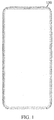
FIG. 1 andFIG. 2 are schematic diagrams of a mobile terminal in a state and at different angles of view according to some embodiments of the present disclosure; -
FIG. 3 is a schematic diagram of a process of rotating a camera out of a mobile terminal according to some embodiments of the present disclosure; -
FIG. 4 andFIG. 5 are schematic diagrams of a mobile terminal in another state and at different angles of view according to some embodiments of the present disclosure; -
FIG. 6 is a schematic diagram of assembling some structures of the camera and a drive structure; -
FIG. 7 is a schematic diagram of assembling a camera and a drive structure; -
FIG. 8 is a schematic exploded diagram of some structures of a mobile terminal according to some embodiments of this disclosure; and -
FIG. 9 is a schematic structural diagram of a part of a mobile terminal according to some embodiments of this disclosure. - 100-housing, 110-frame, 111-hole, 200-camera, 210-box, 211-box body, 211a-first mounting groove, 211b-second mounting groove, 212-camera lens, 213-pressure plate, 220-camera body, 300-drive structure, 310-drive body, 320-gear group, 321-first tapered gear, 322-second tapered gear, 323-third gear, 324-first rotating shaft, 330-guiding rack, 340-decelerator, and 400-second rotating shaft.
- To make the objectives, technical solutions, and advantages of the present disclosure clearer, the following clearly and completely describes the technical solutions of the present disclosure with reference to specific embodiments and corresponding accompanying drawings of the present disclosure. Apparently, the described embodiments are some rather than all of the embodiments of the present disclosure. All other embodiments obtained by a person of ordinary skill in the art based on the embodiments of the present disclosure without creative efforts shall fall within the protection scope of the present disclosure.
- The following describes, in detail with reference to the accompanying drawings, the technical solutions disclosed by various embodiments of the present disclosure.
- Referring to
FIG. 1 to FIG. 9 , some embodiments of the present disclosure disclose a mobile terminal. The disclosed mobile terminal includes ahousing 100, acamera 200, and adrive structure 300. - The
housing 100 is a supporting component of the mobile terminal, and serves as the basis and protection for mounting other components of the mobile terminal. Thehousing 100 has aframe 110 and a cavity, theframe 110 has ahole 111, and thehole 111 is in communication with the cavity. - The
drive structure 300 is disposed in thehousing 100, that is, located in the cavity of thehousing 100. Thecamera 200 is rotatably disposed on thehousing 100, and thecamera 200 may rotate to enter and leave thehole 111. - The
drive structure 300 includes adrive body 310, agear group 320, and a guidingrack 330 fixed in thehousing 100. The guidingrack 330 may be an arc rack. Specifically, the guidingrack 330 may be fixed in thehousing 100 by using a screw. Thecamera 200 is connected to thedrive body 310. Thedrive body 310 cooperates with the guidingrack 330 through rotation by using thegear group 320, and drives thecamera 200 to rotatably enter and leave thehole 111, so that thecamera 200 moves into or moves out of the mobile terminal. - The
drive body 310 meshes with the guidingrack 330 through thegear group 320. In a process of meshing cooperation, because the guidingrack 330 is fixed in thehousing 100, this is equivalent to that thedrive body 310 meshes with the guidingrack 330 through thegear group 320, to rotate relative to the guidingrack 330. Because thedrive body 310 is connected to thecamera 200, rotation of thedrive body 310 drives thecamera 200 to rotate, so that thecamera 200 rotates out of the mobile terminal through thehole 111, to prepare for photographing. After photographing is finished, thedrive body 310 is controlled, so that thegear group 320 meshes with the guidingrack 330 and moves in an opposite direction, so that thecamera 200 is driven to pass through thehole 111 and rotate back into thehousing 100 from outside the mobile terminal. - As can be seen from the foregoing working process, in the mobile terminal disclosed in some embodiments of the present disclosure, the
camera 200 is connected to thedrive body 310, and thegear group 320 meshes with the guidingrack 330, so that thedrive body 310 rotates relative to the guidingrack 330 and finally drives thecamera 200 to rotate to enter and leave thehole 111. In this process, the location of thecamera 200 is changed (moves from inside thehousing 100 to outside thehousing 100 and moves from outside thehousing 100 to inside the housing 100) so that the camera works. Obviously, in the mobile terminal disclosed in the embodiments, disposing of thecamera 200 does not occupy the area for disposing the display screen on the mobile terminal while the photographing function of the mobile terminal is ensured. Therefore, this does not limit further increase of the screen-to-body ratio of the mobile terminal. As can be seen, the mobile terminal disclosed in some embodiments of the present disclosure can resolve the problem that disposing of a camera affects the development of mobile terminals towards a large screen-to-body ratio in the related art. - To achieve a better transmission effect, specifically, the
camera 200 is fixedly connected to thedrive body 310. Specifically, thecamera 200 may include abox 210 and acamera body 220. Thecamera body 220 is a photographing part of thecamera 200, thecamera body 220 is disposed in thebox 210, and thebox 210 may be considered as a housing of thecamera 200 and serves to protect thecamera body 220. Certainly, thebox 210 should not affect photographing of thecamera body 220. A photographing window may be disposed on thebox 210, and the photographing window may be a hole or may be a transparent window such as a glass window. - The
box 210 is fixedly connected to thedrive body 310. In this case, thebox 210 may further serve as the basis for mounting thedrive body 310. - In this embodiment, the
box 210 may include abox body 211 and acamera lens 212, thebox body 211 may have afirst mounting groove 211a, thecamera lens 212 is fixed in an opening of the first mountinggroove 211a, and thecamera lens 212 and the first mountinggroove 211a form a first accommodation space. Thecamera body 220 is disposed in the first accommodation space. Specifically, thecamera body 220 may be fixed in the first accommodation space through bonding, a connecting piece (for example, a thread connecting piece), or a connecting structure (for example, a fastening structure). Thecamera lens 212 is disposed opposite to a lens of thecamera body 220, so that the lens may photograph scenery. Thecamera lens 212 may be considered as the foregoing photographing window. - Usually, the
camera lens 212 is made of a brittle transparent material such as glass, and is fixed on thebox 211 through a connecting piece or a connecting structure. Thecamera lens 212 is easily damaged, for example, is smashed. On this basis, in an optional solution, thecamera lens 212 may be fixed in the opening of the first mountinggroove 211a through bonding. Specifically, thecamera lens 212 may be bonded in the opening of the first mountinggroove 211a through a double-sided tape or a glue dispensing layer. - In an optional solution, the
box body 211 may have asecond mounting groove 211b, thebox 210 may further include apressure plate 213, thepressure plate 213 is fixed in an opening of the second mountinggroove 211b, and thepressure plate 213 and the second mountinggroove 211b form a second accommodation space. Thedrive body 310 may be mounted in the second accommodation space, and thegear group 320 partially passes through thebox 210 and cooperates with theguiding rack 330 through rotation. Abox body 211 is usually provided with an escape hole, and a part of structure of thegear group 320 may pass through the escape hole, to mesh and cooperate with theguiding rack 330. In this solution, thedrive body 310 is disposed in the second accommodation space, and may be further protected by thebox 210 while normal working of thedrive body 310 is not affected. - The
box 210 has a plurality of types of structures and serves as a peripheral component of thecamera 200, as long as thebox 210 may rotatably enter and leave thehole 111 driven by thedrive body 310. To better adapt to rotation and further reduce space occupied in thehousing 100, in an optional solution, a surface between two ends of thebox 210 is an outer circumferential surface, the outer circumferential surface may include a straight segment a and a bent segment b connected to the straight segment a, the bent segment b is located on a same cylindrical surface, and the bent segment b may enter and leave thehole 111 along with thecamera 200. Thebox 210 of this structure undoubtedly can desirably adapt to space enclosed by theguiding rack 330, to reduce overall space occupied by thecamera 200 and thedrive body 310. - It should be noted that two end faces of the
box 210 that separately face and is away from a photographing direction may be considered as a front end face and a rear end face, and a side wall surface between the front end face and the rear end face may be considered as the outer circumferential surface. - Specifically, the straight segment a may block the
hole 111 when thecamera 200 returns to thehousing 100 from thehole 111, so that thecamera 200 returns to thehousing 100. In addition, thehole 111 is blocked, thereby achieving a good dustproof effect. - The
gear group 320 has a plurality of types of structures, and thegear group 320 functions for transmission connection. Still referring toFIG. 6 to FIG. 9 , in a specific implementation, thegear group 320 may include a firsttapered gear 321, a secondtapered gear 322, athird gear 323, and a firstrotating shaft 324. The firsttapered gear 321 is connected to thedrive body 310 through rotation, the secondtapered gear 322 meshes with the firsttapered gear 321, thethird gear 323 and the secondtapered gear 322 are both fixed on the firstrotating shaft 324, and the firstrotating shaft 324 is rotatably disposed on thecamera 200. The firsttapered gear 321 and the secondtapered gear 322 are used, so that a torque transmission direction may change. In this way, thedrive structure 300 is disposed more flexibly, and this helps fully utilize space in thehousing 100 for adaptive disposing. - In an optional solution, the second
rotating shaft 400 may be disposed on thehousing 100, and thecamera 200 is fixed on the secondrotating shaft 400 and therefore may rotate relative to thehousing 100 along with the secondrotating shaft 400. As is known, thecamera 200 and thedrive structure 300 both require a power supply in a working process. To facilitate cabling, in an optional solution, the secondrotating shaft 400 may be a hollow shaft, and a power supply line electrically connected to thecamera 200 and thedrive body 310 may pass through the secondrotating shaft 400, and is electrically connected to a circuit board of the mobile terminal. This disposing direction is equivalent to disposing the power supply line on a rotational axis of thecamera 200. This undoubtedly can alleviate the problem that the power supply line intertwines because of rotation. - In some embodiments of the present disclosure, the
drive body 310 is usually a drive motor. To better control the rotation speed of thecamera 200, thedrive body 310 is usually connected to thegear group 320 through rotation by using adecelerator 340. In the optional solution, thedrive body 310 may be a stepper motor, and the stepper motor can undoubtedly improve driving accuracy. - The mobile terminal disclosed in some embodiments of the present disclosure may be a mobile phone, a tablet computer, an e-book reader, a wearable device, and other devices with a camera and a display screen. Some embodiments of the present disclosure do not limit a specific type of the mobile terminal.
- In the foregoing embodiments of the present disclosure, differences between the various embodiments are mainly described. Different optimized features of the various embodiments may be combined to form better embodiments as long as there is no conflict. Details are not repeated herein for brevity of the text.
- The foregoing descriptions are merely embodiments of this disclosure, but are not intended to limit this disclosure. For a person skilled in the art, the present disclosure may have various changes and variations. Any modification, equivalent replacement, or improvement made without departing from the spirit and principle of this disclosure shall fall within the scope of claims of this disclosure.
Claims (10)
- A mobile terminal, comprising a housing (100), a camera (200), and a drive structure (300) disposed in the housing (100), and a frame (110) of the housing (100) is provided with a hole (111); and
the drive structure (300) comprises a drive body (310), a gear group (320), and a guiding rack (330) fixed in the housing (100), the camera (200) is rotatably disposed on the housing (100) and is connected to the drive body (310), and the drive body (310) cooperates with the guiding rack (330) through rotation by using the gear group (320), and drives the camera (200) to rotatably enter and leave the hole (111). - The mobile terminal according to claim 1, wherein the camera (200) comprises a box (210) and a camera body (220) disposed in the box (210), and the box (210) is fixedly connected to the drive body (310).
- The mobile terminal according to claim 2, wherein the box (210) comprises a box body (211) and a camera lens (212), the box body (211) has a first mounting groove (211a), the camera lens (212) is fixed in an opening of the first mounting groove (211a), the camera lens (212) and the first mounting groove (211a) form a first accommodation space, the camera body (220) is disposed in the first accommodation space, and the camera lens (212) is disposed opposite to a lens of the camera body (220).
- The mobile terminal according to claim 3, wherein the camera lens (212) is fixed in the opening of the first mounting groove (211a) through bonding.
- The mobile terminal according to claim 3, wherein the box body (211) has a second mounting groove (211b), the box (210) further comprises a pressure plate (213), the pressure plate (213) is fixed in an opening of the second mounting groove (211b), the pressure plate (213) and the second mounting groove (211b) form a second accommodation space, the drive body (310) is mounted in the second accommodation space, and the gear group (320) partially passes through the box (210) and cooperates with the guiding rack (330) through rotation.
- The mobile terminal according to claim 2, wherein a surface between two ends of the box (210) is an outer circumferential surface, the outer circumferential surface comprises a straight segment (a) and a bent segment (b) connected to the straight segment (a), the bent segment (b) is located on a same cylindrical surface, and the bent segment (b) may enter and leave the hole (111) along with the camera (200).
- The mobile terminal according to claim 6, wherein the straight segment (a) may block the hole (111) when the camera (200) returns to the housing (100) from the hole (111).
- The mobile terminal according to claim 1, wherein the gear group (320) comprises a first tapered gear (321), a second tapered gear (322), a third gear (323), and a first rotating shaft (324), the first tapered gear (321) is connected to the drive body (310) through rotation, the second tapered gear (322) meshes with the first tapered gear (321), the third gear (323) and the second tapered gear (322) are both fixed on the first rotating shaft (324), and the first rotating shaft (324) is rotatably disposed on the camera (200).
- The mobile terminal according to claim 1, wherein a second rotating shaft (400) is disposed on the housing (100), the camera (200) is fixed on the second rotating shaft (400), the second rotating shaft (400) is a hollow shaft, and a power supply line electrically connected to the camera (200) and the drive body (310) passes through the second rotating shaft (400), and is electrically connected to a circuit board of the mobile terminal.
- The mobile terminal according to claim 1, wherein the drive body (310) is connected to the gear group (320) through transmission by using a decelerator (340), and the drive body (310) is a stepper motor.
Applications Claiming Priority (2)
| Application Number | Priority Date | Filing Date | Title |
|---|---|---|---|
| CN201811008751.2A CN109120755B (en) | 2018-08-30 | 2018-08-30 | Mobile terminal |
| PCT/CN2019/099236 WO2020042873A1 (en) | 2018-08-30 | 2019-08-05 | Mobile terminal |
Publications (3)
| Publication Number | Publication Date |
|---|---|
| EP3846422A1 true EP3846422A1 (en) | 2021-07-07 |
| EP3846422A4 EP3846422A4 (en) | 2021-11-17 |
| EP3846422B1 EP3846422B1 (en) | 2023-05-10 |
Family
ID=64860315
Family Applications (1)
| Application Number | Title | Priority Date | Filing Date |
|---|---|---|---|
| EP19855231.7A Active EP3846422B1 (en) | 2018-08-30 | 2019-08-05 | Mobile terminal |
Country Status (5)
| Country | Link |
|---|---|
| US (1) | US11265405B2 (en) |
| EP (1) | EP3846422B1 (en) |
| CN (1) | CN109120755B (en) |
| ES (1) | ES2946598T3 (en) |
| WO (1) | WO2020042873A1 (en) |
Families Citing this family (14)
| Publication number | Priority date | Publication date | Assignee | Title |
|---|---|---|---|---|
| CN109120755B (en) | 2018-08-30 | 2021-01-08 | 维沃移动通信有限公司 | Mobile terminal |
| CN209994404U (en) * | 2019-03-29 | 2020-01-24 | Oppo广东移动通信有限公司 | Terminal device |
| CN210807348U (en) * | 2019-03-29 | 2020-06-19 | Oppo广东移动通信有限公司 | Camera installation module, camera assembly and mobile terminal |
| CN110049215B (en) * | 2019-04-17 | 2021-08-17 | 广东长盈精密技术有限公司 | Extendable functional components, middle frame components and terminal equipment |
| CN109922182B (en) * | 2019-04-30 | 2021-01-08 | 维沃移动通信(杭州)有限公司 | Terminal device |
| CN209994405U (en) * | 2019-05-07 | 2020-01-24 | Oppo广东移动通信有限公司 | Terminal device |
| CN110248007A (en) * | 2019-06-28 | 2019-09-17 | Oppo广东移动通信有限公司 | Electronic equipment and control method of functional components |
| CN112351120A (en) * | 2019-08-07 | 2021-02-09 | Oppo广东移动通信有限公司 | Mobile terminal |
| CN111474808A (en) * | 2020-05-29 | 2020-07-31 | 维沃移动通信有限公司 | Electronic equipment |
| CN111726440B (en) * | 2020-06-17 | 2021-09-07 | 维沃移动通信(杭州)有限公司 | Electronic device |
| CN112738381A (en) * | 2021-01-19 | 2021-04-30 | 闻泰通讯股份有限公司 | Camera telescopic machanism and electronic equipment |
| CN113050757A (en) * | 2021-03-12 | 2021-06-29 | 联想(北京)有限公司 | Electronic device |
| CN113301197B (en) * | 2021-05-28 | 2024-06-11 | 维沃移动通信有限公司 | Electronic equipment |
| CN113392461B (en) * | 2021-06-29 | 2024-07-05 | 江苏省子午建筑设计有限公司 | A BIM-based architectural design method |
Family Cites Families (22)
| Publication number | Priority date | Publication date | Assignee | Title |
|---|---|---|---|---|
| JP2001245267A (en) * | 2000-02-28 | 2001-09-07 | Matsushita Electric Ind Co Ltd | Portable information communication terminal with video camera |
| WO2006011610A1 (en) * | 2004-07-26 | 2006-02-02 | Ricoh Company, Ltd. | Lens barrel, camera and mobile information terminal |
| KR100652730B1 (en) * | 2005-06-24 | 2006-12-01 | 엘지전자 주식회사 | Camera Rotator in Handheld Terminal |
| JP2014032383A (en) * | 2012-07-12 | 2014-02-20 | Ricoh Co Ltd | Fixing apparatus and image forming apparatus |
| TW201441710A (en) * | 2013-04-30 | 2014-11-01 | Ingrasys Technology Inc | Adjustment apparatus for camera module |
| CN104133281A (en) * | 2013-05-03 | 2014-11-05 | 鸿富锦精密工业(深圳)有限公司 | Adjustment device for lens module |
| CN203965772U (en) * | 2014-05-13 | 2014-11-26 | 深圳市景阳科技股份有限公司 | A kind of infrared monitoring camera focus adjusting mechanism |
| CN203943142U (en) * | 2014-07-23 | 2014-11-19 | 成都百威讯科技有限责任公司 | The wide helmet of monitoring angle |
| CN204131567U (en) * | 2014-09-02 | 2015-01-28 | 黄体辉 | A kind of mobile phone with rotating the small screen |
| CN104468896B (en) * | 2014-12-05 | 2018-04-20 | 广东欧珀移动通信有限公司 | Mobile terminal |
| CN104469114A (en) * | 2014-12-08 | 2015-03-25 | 路宽 | Mobile terminal and full-automatic turnover camera shooting assembly |
| CN206738868U (en) * | 2017-05-11 | 2017-12-12 | 三河市戎邦光电设备股份有限公司 | A kind of tumbler of thermal imaging CCTV camera |
| CN107449781A (en) * | 2017-07-24 | 2017-12-08 | 惠州高视科技有限公司 | The full multi-view image acquisition system of double camera |
| CN107707698A (en) * | 2017-10-24 | 2018-02-16 | 南昌大学 | A kind of screen mobile phone front camera device comprehensively |
| CN207491002U (en) * | 2017-11-24 | 2018-06-12 | 广东欧珀移动通信有限公司 | Camera module and mobile terminal |
| CN207491003U (en) * | 2017-11-24 | 2018-06-12 | 广东欧珀移动通信有限公司 | Mobile terminal |
| CN113099083B (en) * | 2017-11-30 | 2023-04-18 | Oppo广东移动通信有限公司 | Camera assembly, mobile terminal and control method of camera assembly |
| CN108259728A (en) * | 2018-03-29 | 2018-07-06 | 昆山国显光电有限公司 | Display terminal and its photographic device |
| CN109005263B (en) * | 2018-08-30 | 2021-03-23 | 维沃移动通信有限公司 | Mobile terminal |
| CN109120755B (en) * | 2018-08-30 | 2021-01-08 | 维沃移动通信有限公司 | Mobile terminal |
| CN109005264A (en) * | 2018-08-30 | 2018-12-14 | 维沃移动通信有限公司 | a mobile terminal |
| CN109088962A (en) * | 2018-08-30 | 2018-12-25 | 维沃移动通信有限公司 | a mobile terminal |
-
2018
- 2018-08-30 CN CN201811008751.2A patent/CN109120755B/en active Active
-
2019
- 2019-08-05 WO PCT/CN2019/099236 patent/WO2020042873A1/en not_active Ceased
- 2019-08-05 ES ES19855231T patent/ES2946598T3/en active Active
- 2019-08-05 EP EP19855231.7A patent/EP3846422B1/en active Active
-
2021
- 2021-02-26 US US17/186,888 patent/US11265405B2/en active Active
Also Published As
| Publication number | Publication date |
|---|---|
| CN109120755B (en) | 2021-01-08 |
| ES2946598T3 (en) | 2023-07-21 |
| CN109120755A (en) | 2019-01-01 |
| EP3846422A4 (en) | 2021-11-17 |
| WO2020042873A1 (en) | 2020-03-05 |
| US11265405B2 (en) | 2022-03-01 |
| EP3846422B1 (en) | 2023-05-10 |
| US20210185156A1 (en) | 2021-06-17 |
Similar Documents
| Publication | Publication Date | Title |
|---|---|---|
| US11265405B2 (en) | Mobile terminal | |
| CN109005263B (en) | Mobile terminal | |
| EP3863264B1 (en) | Electronic device | |
| CN109088962A (en) | a mobile terminal | |
| EP4040770A1 (en) | Camera module and electronic device | |
| WO2021063231A1 (en) | Photographing module and electronic device | |
| CN210518443U (en) | Electronic device | |
| CN109005264A (en) | a mobile terminal | |
| CN210469397U (en) | Electronic device | |
| WO2020224278A1 (en) | Screen component, mobile phone, and mobile device | |
| WO2021063246A1 (en) | Photographing module and electronic device | |
| US20220166904A1 (en) | Photographing Module and Terminal Device | |
| WO2020200106A1 (en) | Terminal device | |
| WO2021136156A1 (en) | Electronic device | |
| WO2021208919A1 (en) | Electronic device | |
| CN110248007A (en) | Electronic equipment and control method of functional components | |
| CN109302513B (en) | Foldable mobile terminal | |
| CN210112121U (en) | Camera module and electronic device with same | |
| CN209692814U (en) | Screen assembly, mobile phone and mobile device | |
| CN110557545A (en) | Electronic device | |
| CN108924402B (en) | Camera module and terminal equipment | |
| CN110312014A (en) | Electronic device | |
| CN110620598A (en) | Electronic device | |
| CN211580062U (en) | Electronic equipment | |
| CN112511730B (en) | Camera module and electronic equipment |
Legal Events
| Date | Code | Title | Description |
|---|---|---|---|
| STAA | Information on the status of an ep patent application or granted ep patent |
Free format text: STATUS: THE INTERNATIONAL PUBLICATION HAS BEEN MADE |
|
| STAA | Information on the status of an ep patent application or granted ep patent |
Free format text: STATUS: REQUEST FOR EXAMINATION WAS MADE |
|
| PUAI | Public reference made under article 153(3) epc to a published international application that has entered the european phase |
Free format text: ORIGINAL CODE: 0009012 |
|
| 17P | Request for examination filed |
Effective date: 20210330 |
|
| AK | Designated contracting states |
Kind code of ref document: A1 Designated state(s): AL AT BE BG CH CY CZ DE DK EE ES FI FR GB GR HR HU IE IS IT LI LT LU LV MC MK MT NL NO PL PT RO RS SE SI SK SM TR |
|
| A4 | Supplementary search report drawn up and despatched |
Effective date: 20211018 |
|
| RIC1 | Information provided on ipc code assigned before grant |
Ipc: G06F 1/16 20060101ALI20211012BHEP Ipc: H04M 1/02 20060101AFI20211012BHEP |
|
| DAV | Request for validation of the european patent (deleted) | ||
| DAX | Request for extension of the european patent (deleted) | ||
| GRAP | Despatch of communication of intention to grant a patent |
Free format text: ORIGINAL CODE: EPIDOSNIGR1 |
|
| STAA | Information on the status of an ep patent application or granted ep patent |
Free format text: STATUS: GRANT OF PATENT IS INTENDED |
|
| INTG | Intention to grant announced |
Effective date: 20230222 |
|
| GRAS | Grant fee paid |
Free format text: ORIGINAL CODE: EPIDOSNIGR3 |
|
| GRAA | (expected) grant |
Free format text: ORIGINAL CODE: 0009210 |
|
| STAA | Information on the status of an ep patent application or granted ep patent |
Free format text: STATUS: THE PATENT HAS BEEN GRANTED |
|
| AK | Designated contracting states |
Kind code of ref document: B1 Designated state(s): AL AT BE BG CH CY CZ DE DK EE ES FI FR GB GR HR HU IE IS IT LI LT LU LV MC MK MT NL NO PL PT RO RS SE SI SK SM TR |
|
| REG | Reference to a national code |
Ref country code: GB Ref legal event code: FG4D |
|
| REG | Reference to a national code |
Ref country code: AT Ref legal event code: REF Ref document number: 1567873 Country of ref document: AT Kind code of ref document: T Effective date: 20230515 Ref country code: CH Ref legal event code: EP |
|
| REG | Reference to a national code |
Ref country code: DE Ref legal event code: R096 Ref document number: 602019028901 Country of ref document: DE |
|
| REG | Reference to a national code |
Ref country code: IE Ref legal event code: FG4D |
|
| REG | Reference to a national code |
Ref country code: NL Ref legal event code: FP |
|
| REG | Reference to a national code |
Ref country code: ES Ref legal event code: FG2A Ref document number: 2946598 Country of ref document: ES Kind code of ref document: T3 Effective date: 20230721 |
|
| P01 | Opt-out of the competence of the unified patent court (upc) registered |
Effective date: 20230704 |
|
| REG | Reference to a national code |
Ref country code: LT Ref legal event code: MG9D |
|
| REG | Reference to a national code |
Ref country code: AT Ref legal event code: MK05 Ref document number: 1567873 Country of ref document: AT Kind code of ref document: T Effective date: 20230510 |
|
| PG25 | Lapsed in a contracting state [announced via postgrant information from national office to epo] |
Ref country code: SE Free format text: LAPSE BECAUSE OF FAILURE TO SUBMIT A TRANSLATION OF THE DESCRIPTION OR TO PAY THE FEE WITHIN THE PRESCRIBED TIME-LIMIT Effective date: 20230510 Ref country code: PT Free format text: LAPSE BECAUSE OF FAILURE TO SUBMIT A TRANSLATION OF THE DESCRIPTION OR TO PAY THE FEE WITHIN THE PRESCRIBED TIME-LIMIT Effective date: 20230911 Ref country code: NO Free format text: LAPSE BECAUSE OF FAILURE TO SUBMIT A TRANSLATION OF THE DESCRIPTION OR TO PAY THE FEE WITHIN THE PRESCRIBED TIME-LIMIT Effective date: 20230810 Ref country code: AT Free format text: LAPSE BECAUSE OF FAILURE TO SUBMIT A TRANSLATION OF THE DESCRIPTION OR TO PAY THE FEE WITHIN THE PRESCRIBED TIME-LIMIT Effective date: 20230510 |
|
| PG25 | Lapsed in a contracting state [announced via postgrant information from national office to epo] |
Ref country code: RS Free format text: LAPSE BECAUSE OF FAILURE TO SUBMIT A TRANSLATION OF THE DESCRIPTION OR TO PAY THE FEE WITHIN THE PRESCRIBED TIME-LIMIT Effective date: 20230510 Ref country code: PL Free format text: LAPSE BECAUSE OF FAILURE TO SUBMIT A TRANSLATION OF THE DESCRIPTION OR TO PAY THE FEE WITHIN THE PRESCRIBED TIME-LIMIT Effective date: 20230510 Ref country code: LV Free format text: LAPSE BECAUSE OF FAILURE TO SUBMIT A TRANSLATION OF THE DESCRIPTION OR TO PAY THE FEE WITHIN THE PRESCRIBED TIME-LIMIT Effective date: 20230510 Ref country code: LT Free format text: LAPSE BECAUSE OF FAILURE TO SUBMIT A TRANSLATION OF THE DESCRIPTION OR TO PAY THE FEE WITHIN THE PRESCRIBED TIME-LIMIT Effective date: 20230510 Ref country code: IS Free format text: LAPSE BECAUSE OF FAILURE TO SUBMIT A TRANSLATION OF THE DESCRIPTION OR TO PAY THE FEE WITHIN THE PRESCRIBED TIME-LIMIT Effective date: 20230910 Ref country code: HR Free format text: LAPSE BECAUSE OF FAILURE TO SUBMIT A TRANSLATION OF THE DESCRIPTION OR TO PAY THE FEE WITHIN THE PRESCRIBED TIME-LIMIT Effective date: 20230510 Ref country code: GR Free format text: LAPSE BECAUSE OF FAILURE TO SUBMIT A TRANSLATION OF THE DESCRIPTION OR TO PAY THE FEE WITHIN THE PRESCRIBED TIME-LIMIT Effective date: 20230811 |
|
| PG25 | Lapsed in a contracting state [announced via postgrant information from national office to epo] |
Ref country code: FI Free format text: LAPSE BECAUSE OF FAILURE TO SUBMIT A TRANSLATION OF THE DESCRIPTION OR TO PAY THE FEE WITHIN THE PRESCRIBED TIME-LIMIT Effective date: 20230510 |
|
| PG25 | Lapsed in a contracting state [announced via postgrant information from national office to epo] |
Ref country code: SK Free format text: LAPSE BECAUSE OF FAILURE TO SUBMIT A TRANSLATION OF THE DESCRIPTION OR TO PAY THE FEE WITHIN THE PRESCRIBED TIME-LIMIT Effective date: 20230510 |
|
| PG25 | Lapsed in a contracting state [announced via postgrant information from national office to epo] |
Ref country code: SM Free format text: LAPSE BECAUSE OF FAILURE TO SUBMIT A TRANSLATION OF THE DESCRIPTION OR TO PAY THE FEE WITHIN THE PRESCRIBED TIME-LIMIT Effective date: 20230510 Ref country code: SK Free format text: LAPSE BECAUSE OF FAILURE TO SUBMIT A TRANSLATION OF THE DESCRIPTION OR TO PAY THE FEE WITHIN THE PRESCRIBED TIME-LIMIT Effective date: 20230510 Ref country code: RO Free format text: LAPSE BECAUSE OF FAILURE TO SUBMIT A TRANSLATION OF THE DESCRIPTION OR TO PAY THE FEE WITHIN THE PRESCRIBED TIME-LIMIT Effective date: 20230510 Ref country code: EE Free format text: LAPSE BECAUSE OF FAILURE TO SUBMIT A TRANSLATION OF THE DESCRIPTION OR TO PAY THE FEE WITHIN THE PRESCRIBED TIME-LIMIT Effective date: 20230510 Ref country code: DK Free format text: LAPSE BECAUSE OF FAILURE TO SUBMIT A TRANSLATION OF THE DESCRIPTION OR TO PAY THE FEE WITHIN THE PRESCRIBED TIME-LIMIT Effective date: 20230510 Ref country code: CZ Free format text: LAPSE BECAUSE OF FAILURE TO SUBMIT A TRANSLATION OF THE DESCRIPTION OR TO PAY THE FEE WITHIN THE PRESCRIBED TIME-LIMIT Effective date: 20230510 |
|
| REG | Reference to a national code |
Ref country code: DE Ref legal event code: R097 Ref document number: 602019028901 Country of ref document: DE |
|
| PG25 | Lapsed in a contracting state [announced via postgrant information from national office to epo] |
Ref country code: MC Free format text: LAPSE BECAUSE OF FAILURE TO SUBMIT A TRANSLATION OF THE DESCRIPTION OR TO PAY THE FEE WITHIN THE PRESCRIBED TIME-LIMIT Effective date: 20230510 |
|
| PLBE | No opposition filed within time limit |
Free format text: ORIGINAL CODE: 0009261 |
|
| STAA | Information on the status of an ep patent application or granted ep patent |
Free format text: STATUS: NO OPPOSITION FILED WITHIN TIME LIMIT |
|
| REG | Reference to a national code |
Ref country code: CH Ref legal event code: PL |
|
| PG25 | Lapsed in a contracting state [announced via postgrant information from national office to epo] |
Ref country code: MC Free format text: LAPSE BECAUSE OF FAILURE TO SUBMIT A TRANSLATION OF THE DESCRIPTION OR TO PAY THE FEE WITHIN THE PRESCRIBED TIME-LIMIT Effective date: 20230510 |
|
| PG25 | Lapsed in a contracting state [announced via postgrant information from national office to epo] |
Ref country code: LU Free format text: LAPSE BECAUSE OF NON-PAYMENT OF DUE FEES Effective date: 20230805 |
|
| 26N | No opposition filed |
Effective date: 20240213 |
|
| PG25 | Lapsed in a contracting state [announced via postgrant information from national office to epo] |
Ref country code: LU Free format text: LAPSE BECAUSE OF NON-PAYMENT OF DUE FEES Effective date: 20230805 Ref country code: CH Free format text: LAPSE BECAUSE OF NON-PAYMENT OF DUE FEES Effective date: 20230831 |
|
| PG25 | Lapsed in a contracting state [announced via postgrant information from national office to epo] |
Ref country code: SI Free format text: LAPSE BECAUSE OF FAILURE TO SUBMIT A TRANSLATION OF THE DESCRIPTION OR TO PAY THE FEE WITHIN THE PRESCRIBED TIME-LIMIT Effective date: 20230510 |
|
| REG | Reference to a national code |
Ref country code: BE Ref legal event code: MM Effective date: 20230831 |
|
| REG | Reference to a national code |
Ref country code: IE Ref legal event code: MM4A |
|
| PG25 | Lapsed in a contracting state [announced via postgrant information from national office to epo] |
Ref country code: SI Free format text: LAPSE BECAUSE OF FAILURE TO SUBMIT A TRANSLATION OF THE DESCRIPTION OR TO PAY THE FEE WITHIN THE PRESCRIBED TIME-LIMIT Effective date: 20230510 |
|
| PG25 | Lapsed in a contracting state [announced via postgrant information from national office to epo] |
Ref country code: IE Free format text: LAPSE BECAUSE OF NON-PAYMENT OF DUE FEES Effective date: 20230805 |
|
| PG25 | Lapsed in a contracting state [announced via postgrant information from national office to epo] |
Ref country code: IE Free format text: LAPSE BECAUSE OF NON-PAYMENT OF DUE FEES Effective date: 20230805 |
|
| PG25 | Lapsed in a contracting state [announced via postgrant information from national office to epo] |
Ref country code: BE Free format text: LAPSE BECAUSE OF NON-PAYMENT OF DUE FEES Effective date: 20230831 |
|
| PG25 | Lapsed in a contracting state [announced via postgrant information from national office to epo] |
Ref country code: BG Free format text: LAPSE BECAUSE OF FAILURE TO SUBMIT A TRANSLATION OF THE DESCRIPTION OR TO PAY THE FEE WITHIN THE PRESCRIBED TIME-LIMIT Effective date: 20230510 |
|
| PG25 | Lapsed in a contracting state [announced via postgrant information from national office to epo] |
Ref country code: BG Free format text: LAPSE BECAUSE OF FAILURE TO SUBMIT A TRANSLATION OF THE DESCRIPTION OR TO PAY THE FEE WITHIN THE PRESCRIBED TIME-LIMIT Effective date: 20230510 |
|
| PGFP | Annual fee paid to national office [announced via postgrant information from national office to epo] |
Ref country code: GB Payment date: 20250626 Year of fee payment: 7 |
|
| PG25 | Lapsed in a contracting state [announced via postgrant information from national office to epo] |
Ref country code: CY Free format text: LAPSE BECAUSE OF FAILURE TO SUBMIT A TRANSLATION OF THE DESCRIPTION OR TO PAY THE FEE WITHIN THE PRESCRIBED TIME-LIMIT; INVALID AB INITIO Effective date: 20190805 |
|
| PG25 | Lapsed in a contracting state [announced via postgrant information from national office to epo] |
Ref country code: HU Free format text: LAPSE BECAUSE OF FAILURE TO SUBMIT A TRANSLATION OF THE DESCRIPTION OR TO PAY THE FEE WITHIN THE PRESCRIBED TIME-LIMIT; INVALID AB INITIO Effective date: 20190805 |
|
| PGFP | Annual fee paid to national office [announced via postgrant information from national office to epo] |
Ref country code: NL Payment date: 20250704 Year of fee payment: 7 |
|
| PGFP | Annual fee paid to national office [announced via postgrant information from national office to epo] |
Ref country code: ES Payment date: 20250909 Year of fee payment: 7 |
|
| PGFP | Annual fee paid to national office [announced via postgrant information from national office to epo] |
Ref country code: DE Payment date: 20250702 Year of fee payment: 7 |
|
| PGFP | Annual fee paid to national office [announced via postgrant information from national office to epo] |
Ref country code: IT Payment date: 20250722 Year of fee payment: 7 |
|
| PGFP | Annual fee paid to national office [announced via postgrant information from national office to epo] |
Ref country code: FR Payment date: 20250703 Year of fee payment: 7 |
|
| PG25 | Lapsed in a contracting state [announced via postgrant information from national office to epo] |
Ref country code: TR Free format text: LAPSE BECAUSE OF FAILURE TO SUBMIT A TRANSLATION OF THE DESCRIPTION OR TO PAY THE FEE WITHIN THE PRESCRIBED TIME-LIMIT Effective date: 20230510 |