EP3846358A1 - Système et procédé d'étalonnage d'une antenne - Google Patents
Système et procédé d'étalonnage d'une antenne Download PDFInfo
- Publication number
- EP3846358A1 EP3846358A1 EP20215317.7A EP20215317A EP3846358A1 EP 3846358 A1 EP3846358 A1 EP 3846358A1 EP 20215317 A EP20215317 A EP 20215317A EP 3846358 A1 EP3846358 A1 EP 3846358A1
- Authority
- EP
- European Patent Office
- Prior art keywords
- spacecraft
- phase
- tilt
- location
- antenna
- Prior art date
- Legal status (The legal status is an assumption and is not a legal conclusion. Google has not performed a legal analysis and makes no representation as to the accuracy of the status listed.)
- Granted
Links
- 238000000034 method Methods 0.000 title claims abstract description 97
- 239000011159 matrix material Substances 0.000 claims abstract description 41
- 230000015654 memory Effects 0.000 claims description 9
- 238000005259 measurement Methods 0.000 description 34
- 238000004088 simulation Methods 0.000 description 4
- 238000004891 communication Methods 0.000 description 3
- 230000004075 alteration Effects 0.000 description 2
- 238000004458 analytical method Methods 0.000 description 2
- 239000000872 buffer Substances 0.000 description 2
- 230000006870 function Effects 0.000 description 2
- 238000004519 manufacturing process Methods 0.000 description 2
- 238000012986 modification Methods 0.000 description 2
- 230000004048 modification Effects 0.000 description 2
- 230000003287 optical effect Effects 0.000 description 2
- 230000008569 process Effects 0.000 description 2
- 238000012545 processing Methods 0.000 description 2
- 238000012935 Averaging Methods 0.000 description 1
- 230000009471 action Effects 0.000 description 1
- 230000015572 biosynthetic process Effects 0.000 description 1
- 230000008859 change Effects 0.000 description 1
- 238000007796 conventional method Methods 0.000 description 1
- 230000001934 delay Effects 0.000 description 1
- 238000011156 evaluation Methods 0.000 description 1
- 238000001914 filtration Methods 0.000 description 1
- 230000010365 information processing Effects 0.000 description 1
- 238000003672 processing method Methods 0.000 description 1
- 238000004549 pulsed laser deposition Methods 0.000 description 1
- 238000005070 sampling Methods 0.000 description 1
- 239000004065 semiconductor Substances 0.000 description 1
- 238000001228 spectrum Methods 0.000 description 1
- 230000003068 static effect Effects 0.000 description 1
- 238000012360 testing method Methods 0.000 description 1
- 230000009466 transformation Effects 0.000 description 1
Images


Classifications
-
- H—ELECTRICITY
- H01—ELECTRIC ELEMENTS
- H01Q—ANTENNAS, i.e. RADIO AERIALS
- H01Q1/00—Details of, or arrangements associated with, antennas
- H01Q1/27—Adaptation for use in or on movable bodies
- H01Q1/28—Adaptation for use in or on aircraft, missiles, satellites, or balloons
- H01Q1/288—Satellite antennas
-
- H—ELECTRICITY
- H04—ELECTRIC COMMUNICATION TECHNIQUE
- H04B—TRANSMISSION
- H04B17/00—Monitoring; Testing
- H04B17/20—Monitoring; Testing of receivers
- H04B17/27—Monitoring; Testing of receivers for locating or positioning the transmitter
-
- H—ELECTRICITY
- H01—ELECTRIC ELEMENTS
- H01Q—ANTENNAS, i.e. RADIO AERIALS
- H01Q3/00—Arrangements for changing or varying the orientation or the shape of the directional pattern of the waves radiated from an antenna or antenna system
- H01Q3/26—Arrangements for changing or varying the orientation or the shape of the directional pattern of the waves radiated from an antenna or antenna system varying the relative phase or relative amplitude of energisation between two or more active radiating elements; varying the distribution of energy across a radiating aperture
- H01Q3/267—Phased-array testing or checking devices
-
- H—ELECTRICITY
- H01—ELECTRIC ELEMENTS
- H01Q—ANTENNAS, i.e. RADIO AERIALS
- H01Q3/00—Arrangements for changing or varying the orientation or the shape of the directional pattern of the waves radiated from an antenna or antenna system
- H01Q3/26—Arrangements for changing or varying the orientation or the shape of the directional pattern of the waves radiated from an antenna or antenna system varying the relative phase or relative amplitude of energisation between two or more active radiating elements; varying the distribution of energy across a radiating aperture
- H01Q3/30—Arrangements for changing or varying the orientation or the shape of the directional pattern of the waves radiated from an antenna or antenna system varying the relative phase or relative amplitude of energisation between two or more active radiating elements; varying the distribution of energy across a radiating aperture varying the relative phase between the radiating elements of an array
- H01Q3/34—Arrangements for changing or varying the orientation or the shape of the directional pattern of the waves radiated from an antenna or antenna system varying the relative phase or relative amplitude of energisation between two or more active radiating elements; varying the distribution of energy across a radiating aperture varying the relative phase between the radiating elements of an array by electrical means
- H01Q3/36—Arrangements for changing or varying the orientation or the shape of the directional pattern of the waves radiated from an antenna or antenna system varying the relative phase or relative amplitude of energisation between two or more active radiating elements; varying the distribution of energy across a radiating aperture varying the relative phase between the radiating elements of an array by electrical means with variable phase-shifters
-
- H—ELECTRICITY
- H01—ELECTRIC ELEMENTS
- H01Q—ANTENNAS, i.e. RADIO AERIALS
- H01Q3/00—Arrangements for changing or varying the orientation or the shape of the directional pattern of the waves radiated from an antenna or antenna system
- H01Q3/26—Arrangements for changing or varying the orientation or the shape of the directional pattern of the waves radiated from an antenna or antenna system varying the relative phase or relative amplitude of energisation between two or more active radiating elements; varying the distribution of energy across a radiating aperture
- H01Q3/30—Arrangements for changing or varying the orientation or the shape of the directional pattern of the waves radiated from an antenna or antenna system varying the relative phase or relative amplitude of energisation between two or more active radiating elements; varying the distribution of energy across a radiating aperture varying the relative phase between the radiating elements of an array
- H01Q3/34—Arrangements for changing or varying the orientation or the shape of the directional pattern of the waves radiated from an antenna or antenna system varying the relative phase or relative amplitude of energisation between two or more active radiating elements; varying the distribution of energy across a radiating aperture varying the relative phase between the radiating elements of an array by electrical means
- H01Q3/40—Arrangements for changing or varying the orientation or the shape of the directional pattern of the waves radiated from an antenna or antenna system varying the relative phase or relative amplitude of energisation between two or more active radiating elements; varying the distribution of energy across a radiating aperture varying the relative phase between the radiating elements of an array by electrical means with phasing matrix
-
- H—ELECTRICITY
- H04—ELECTRIC COMMUNICATION TECHNIQUE
- H04B—TRANSMISSION
- H04B7/00—Radio transmission systems, i.e. using radiation field
- H04B7/14—Relay systems
- H04B7/15—Active relay systems
- H04B7/185—Space-based or airborne stations; Stations for satellite systems
- H04B7/1851—Systems using a satellite or space-based relay
- H04B7/18515—Transmission equipment in satellites or space-based relays
Definitions
- the present disclosure is directed to systems and methods for calibrating an antenna. More particularly, the present disclosure is directed to systems and methods for performing point calibration for a phase-array antenna in orbit.
- Spacecrafts such as satellites have an antenna for communication purposes.
- the antenna cannot be aligned perfectly on the ground.
- the antenna is typically aligned after the spacecraft is launched into space (e.g., orbit).
- the alignment of the antenna may be calibrated to reduce alignment errors such as fixed alignment errors.
- a "fixed alignment error” refers to a transformation error between two coordinate systems.
- the first coordinate system may be a star-tracker coordinate system on the spacecraft, which determines the attitude of the spacecraft.
- the second coordinate system may be a phase array antenna coordinate system (e.g., on the spacecraft).
- Conventional calibration techniques may include antenna beam cuts that involve slewing the antenna and then correlating the measurements from the antenna to predetermined beam patterns.
- slewing the antenna while performing antenna beam cuts is a time-consuming procedure. Therefore, it would be desirable to have an improved system and method for calibrating an antenna.
- a method for calibrating an antenna includes receiving a plurality of signals transmitted from an antenna on a spacecraft.
- the antenna includes a plurality of phase array elements.
- the method also includes determining a phase tilt of the phase array elements based at least partially upon the signals.
- the method also includes determining a first location of the spacecraft, a first attitude of the spacecraft, or both.
- the method also includes removing a first portion from the determined phase tilt. The first portion is caused by the first location of the spacecraft, the first attitude of the spacecraft, or both.
- the method also includes estimating the phase tilt of the phase array elements after the first portion is removed.
- the method also includes generating a reference tilt matrix for the phase array elements.
- the method also includes comparing the estimated phase tilt to the reference tilt matrix.
- the method also includes determining a pointing error of the antenna based at least partially upon the comparison.
- a method for calibrating an antenna on a spacecraft in orbit includes receiving a first plurality of signals at a computing system on the ground.
- the first plurality of signals are transmitted from a transmitter antenna on a spacecraft when the spacecraft is at a first location and has a first attitude.
- the transmitter antenna includes a plurality of phase array elements.
- the method also includes determining, using the computing system, a first phase tilt of the phase array elements based at least partially upon the first plurality of signals.
- the method also includes determining the first location of the spacecraft.
- the method also includes determining the first attitude of the spacecraft.
- the method also includes removing a first portion from the determined first phase tilt. The first portion is caused by the first location of the spacecraft, the first attitude of the spacecraft, or both.
- the method also includes estimating the first phase tilt of the phase array elements after the first portion of the first phase tilt is removed.
- the method also includes receiving a second plurality of signals at the computing system on the ground. The second plurality of signals are transmitted from the transmitter antenna on the spacecraft when the spacecraft is at a second location and has a second attitude.
- the method also includes determining, using the computing system, a second phase tilt of the phase array elements based at least partially upon the second plurality of signals.
- the method also includes determining the second location of the spacecraft.
- the method also includes determining the second attitude of the spacecraft.
- the method also includes removing a first portion from the determined second phase tilt. The first portion is caused by the second location of the spacecraft, the second attitude of the spacecraft, or both.
- the method also includes estimating the second phase tilt of the phase array elements after the first portion of the second phase tilt is removed.
- the method also includes generating a reference tilt matrix for the phase array elements based at least partially upon the first location of the spacecraft and the second location of the spacecraft.
- the method also includes comparing the estimated first phase tilt to the reference tilt matrix to produce a first set of misalignment errors.
- the method also includes comparing the estimated second phase tilt to the reference tilt matrix to produce a second set of misalignment errors.
- the method also includes determining an intersection of the first set of misalignment errors and the second set of misalignment errors. The intersection represents a pointing error of the antenna.
- a computing system includes one or more processors and a memory system.
- the memory system includes one or more non-transitory computer-readable media storing instructions that, when executed by at least one of the one or more processors, cause the computing system to perform operations.
- the operations includes receiving a plurality of signals transmitted from an antenna on a spacecraft.
- the antenna includes a plurality of phase array elements.
- the operations also include determining a phase tilt of the phase array elements based at least partially upon the signals.
- the operations also include determining a first location of the spacecraft, a first attitude of the spacecraft, or both.
- the operations also include removing a first portion from the determined phase tilt. The first portion is caused by the first location of the spacecraft, the first attitude of the spacecraft, or both.
- the operations also include estimating the phase tilt of the phase array elements after the first portion is removed.
- the operations also include generating a reference tilt matrix for the phase array elements.
- the operations also include comparing the estimated phase tilt to the reference tilt matrix.
- the operations also include determining a pointing error of the antenna based at least partially upon the comparison.
- the present disclosure is directed to a system and method for performing pointing calibration of a spacecraft (e.g., an antenna in orbit) to reduce a fixed alignment error and/or an array pointing error. More particularly, the present disclosure is directed to a system and method for performing pointing calibration of a phase array antenna on the spacecraft utilizing a two-dimensional (2D) linear fit phase tilt to estimate and correct the errors. This may include obtaining measurements at two or more different spacecraft locations and/or orientations, and using the measurements to estimate the azimuth fixed error, elevation fixed error, and yaw fixed error. The method does not involve slewing the antenna. As a result, the method may be performed more quickly than conventional methods that slew the antenna.
- a spacecraft e.g., an antenna in orbit
- 2D two-dimensional
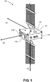
- Figure 1 illustrates a perspective view of an aircraft (e.g., a spacecraft) 100, according to an implementation.
- the spacecraft 100 may be or include a satellite that is configured to be placed into orbit around, for example, the Earth.
- the spacecraft 100 may be able to move (e.g., rotate) around a first axis (e.g., an X axis). This movement is referred to as a roll of the spacecraft 100.
- the spacecraft 100 may also be able to move (e.g., rotate) around a second axis (e.g., a Y axis). This movement is referred to as a pitch of the spacecraft 100.
- the spacecraft 100 may also be able to move (e.g., rotate) around a third axis (e.g., a Z axis). This movement is referred to as a yaw of the spacecraft 100.
- the spacecraft 100 may include a transmitter antenna 110A and a receiver antenna 110B.
- the transmitter antenna 110A and the receiver antenna 110B may be or include phase array antennas.
- the transmitter antenna 110A and the receiver antenna 110B may each include a plurality of phase array elements in a predefined pattern (as shown in Figure 4 ).
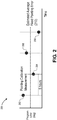
- FIG. 2 illustrates a graph 200 showing a pointing error (in degrees) of the transmitter antenna 110A versus time over the course of a single day, according to an implementation.
- the spacecraft 100 may pass overhead of a gateway on Earth one or more times during the day. For example, the spacecraft 100 may pass over the gateway four times a day (e.g., every 6 hours).
- a "gateway" refers to a ground terminal that is configured to transmit signals to the spacecraft 100, receive signals from the spacecraft 100, and process the signals (e.g., using a computing system).
- An illustrative computing system 1400 that may be used at the ground terminal is described below with reference to Figure 14 .
- the pointing error may be measured each time the spacecraft 100 passes over the gateway.
- Each set 202, 204, 206, 208 may include a plurality of measurements (e.g., 10 measurements).
- the sets of pointing error measurements 202, 204, 206, 208 may vary from time to time.
- the pointing error of the first set 202 is greater than the pointing error of the second set 204. This may be due to temperature variations throughout the day.
- an average fixed pointing error 210 may be determined based upon the pointing error measurement sets 202, 204, 206, 208.
- the average fixed pointing error 210 may at least partially remove fixed pointing error.
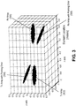
- Figure 3 illustrates a graph 300 showing a pointing error spatial simulation of the transmitter antenna 110A and the receiver antenna 110B, according to an implementation.
- a first set of element locations 302 and a second set of locations 304 represent the location of phase array elements of the transmitter antenna 110A.
- the first set of element locations 302 is without pointing error
- the second set of element locations 304 includes the pointing error.
- a third set of element locations 306 and a fourth set of element locations 308 represent the location of phase array elements of the receiver antenna 110B.
- the third set of element locations 306 is without pointing error
- the fourth set of element locations 308 includes the pointing error.
- FIG. 4 illustrates a graph 400 of the element locations 302 looking downward along the Z-axis in the graph 300, according to an implementation.
- each element location 302 represents the location of the phase array elements of the transmitter antenna 110A.
- the element locations 302 vary along the X-axis and the Y-axis and produce a phase measurement for each element.
- Figure 5 illustrates a flowchart of a method 500 for calibrating the transmitter antenna 110A of the spacecraft 100, according to an implementation.
- the method 500 may be used to average-out diurnal-induced and/or temperature-induced alignment errors of the transmitter antenna 110A.
- the method 500 is described with reference to the transmitter antenna 110A, it may also or instead be used to calibrate the receiver antenna 110B.
- the method 500 An illustrative order of the method 500 is described below; however, it will be appreciated that one or more steps of the method 500 may be performed in a different order or omitted altogether. At least a portion of the method 500 may be performed while the spacecraft 100 is in flight and/or space. For example, at least a portion of the method 500 may be performed while the transmitter antenna 110A is in orbit.
- the method 500 may include receiving a plurality of signals from the transmitter antenna 110A, as at 502.
- the signals may be generated by the phase array elements of the transmitter antenna 110A.
- the signals may be received at the gateway on the ground.
- the signals may be received by the computing system 1400 at the gateway, and the computing system 1400 may measure the signals and/or determine how the transmitter antenna 110A should be calibrated based upon the signals, as described below.
- Each of the signals may be or include a tone at a different (e.g., unique) frequency.
- the method 500 may also include measuring or determining a phase tilt (also referred to as a phase slope) of the phase array elements of the transmitter antenna 110A based at least partially upon the signals (from 502), as at 504.
- the phase tilt may be measured by a vector spectrum analyzer (VSA), which may be a part of (or in communication with) the computing system 1400.
- VSA vector spectrum analyzer
- the "phase tilt” refers to a linear phase change versus distance.
- the method 500 may also include determining a location of the spacecraft 100 (e.g., in orbit), as at 506.
- the location may be measured by a location sensor (e.g., a global positioning system (GPS)) 120 on the spacecraft 100.
- the method 500 may also include determining an attitude of the spacecraft 100 (e.g., in orbit), as at 508.
- the attitude may be measured by an attitude sensor 122 on the spacecraft 100.
- the location and the attitude may be transmitted from the spacecraft 100 to the computing system 1400 at the gateway, which may make the determinations (at 506 and 508).
- the location and/or the attitude may be determined when the signals are generated (at 502) at the spacecraft 100 and/or received at the gateway.
- the phase tilt (measured at 504) may depend at least partially upon the location of the spacecraft (determined at 506), the attitude of the spacecraft 100 (measured at 508), and a misalignment error of the transmitter antenna 110A.
- the method 500 may also include removing a first portion of the phase tilt from the phase tilt measured at 504, as at 510. The first portion of the phase tilt is caused by the location and/or attitude of the spacecraft 100.
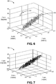
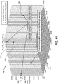
- Figure 6 illustrates a graph 600 of the phase tilt of the phase array elements of the transmitter antenna 110A with a physical delay variation caused by the array element pointing alignment error of the transmitter antenna 110 (e.g., physical misalignment) 610 and a digital delay variation caused by a digital signal processor (DSP) delay error 620, according to an implementation.
- Figure 6 includes both the physical and digital delay variations which create the outlier measurement values (i.e., DSP delay error 620).
- the DSP 124 that creates the DSP delay error 620 may be onboard the spacecraft 100 (see Figure 1 ).
- the method 500 may also include removing a second portion of the phase tilt from the phase tilt measured at 504, as at 512.
- the second portion of the phase tilt is caused by the DSP delay error 620.
- An example of this is shown in Figure 7 , which illustrates a graph 700 of the phase tilt of the phase array elements of the transmitter antenna 110A with the DSP delay error 620 (from Figure 6 ) removed, according to an implementation.
- Figure 7 is similar to Figure 3 , but focuses on the second set of measurements 304 (e.g., the location of the phase array elements of the transmitter antenna 110A with pointing error).
- Figure 7 only shows the error from physical misalignment.
- the DSP 124 has a plurality of discrete states, and each state has a different (e.g., unique) digital delay variation.
- the digital delay variation refers to discrete steps (e.g., at some fixed interval such as 60 picoseconds (ps), 120 ps, 180 ps, etc.) based on the DSP clock frequency.
- ps picoseconds
- the DSP 124 wakes up in one of the discrete states (e.g., randomly).
- the DSP 124 wakes up with a random discrete step digital delay variation that is caused by an analog-to-digital converter (ADC) and/or a digital-to-analog converter (DAC) and a sampling clock.
- ADC analog-to-digital converter
- DAC digital-to-analog converter
- the digital delay variation may be estimated and modified (e.g., corrected) through DSP delay buffers.
- the measurement by the computing system 1400 at the gateway of the phase across the transmitter antenna 110A may include both the physical delay variations and the digital delay variations.
- the modified (e.g., corrected) delay variation e.g., using initial estimates of the discrete delay offsets, modulus of the measured element delays, and DSP discrete delay step
- a user may determine whether the digital delay variation was over-estimated or underestimated. Once the phase array elements that are affected by the incorrect digital delay variations are identified, a final delay buffer setting may be determined.
- the method 500 may also include estimating the phase tilt of the phase array elements of the transmitter antenna 110A, as at 514.
- the phase tilt may be estimated after the first portion is removed (at 510) and/or the second portion is removed (at 512).
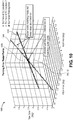
- An example of the estimated phase tilt is shown in Figure 8A , which illustrates a graph 800 showing the phase tilt (in degrees) versus the location of the phase array elements of the transmitter antenna 110A (in meters), according to an implementation.
- the points (e.g., 802, 804, 806, etc.) on the graph 800 represent the phase measurement of the phase array elements.
- each point 802, 804, 806 may represent the phase measurement of the phase array elements at a different pass over the gateway.
- the plane 810 represents a 2D polyfit of the phase tilt of the points 802, 804, 806.
- Figure 8B illustrates a table 850 showing the azimuth error (in degrees), the elevation error (in degrees), the X slope coefficient (in degrees per meter), the Y slope coefficient (in degrees per meter), the delta X coefficient (in degrees per meter), and the delta Y coefficient (in degrees per meter), according to an implementation. These values may be determined using the computing system 1400 based at least partially upon the estimated phase tilt of the phase array element elements of the transmitter antenna 110A (from 514).
- the foregoing portion of the method 500 may be performed a first time using data/measurements from a first spacecraft location in orbit.
- the foregoing portion of the method 500 (e.g., steps 502-514) may then be repeated in an iterative fashion one or more times using data/measurements from one or more different spacecraft locations in orbit.
- the steps 502-514 have been performed/repeated a second time at a second spacecraft location.
- the method 500 may also include generating a reference tilt matrix for the phase array elements of the transmitter antenna 110A at the first spacecraft location and the second spacecraft location, as at 516.
- the reference tilt matrix may be generated based at least partially upon the first and second spacecraft locations (from two iterations of 506), the first and second spacecraft attitudes (from two iterations of 508), and the gateway location (which is constant).
- generating the reference tilt matrix may include generating an expected phase tilt for a set of misalignment errors.
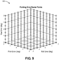
- Figure 9 illustrates a graph 900 of the reference tilt matrix for the phase array elements of the transmitter antenna 110A, according to an implementation.
- a first axis of the graph 900 represents a roll error (in degrees)
- a second axis of the graph 900 represents a pitch error (in degrees)
- a third axis of the graph 900 represents a yaw error (in degrees).
- the matrix is generated with an expected phase tilt at each 0.01 degree raster point.
- Four 3D matrices may be generated per array: one matrix at each of the two spacecraft locations, one matrix for the X slope, and one matrix for the Y slope.
- four measurements may be used to determine the three unknowns (e.g., roll, pitch, and yaw) per array.
- the method 500 may also include comparing the estimated phase tilt of the phase array elements of the transmitter antenna 110A (at 514) to the reference tilt matrix (at 516), as at 518. This may produce a set of misalignment errors 1002 that match the estimated phase tilt for the first spacecraft location and a set of misalignment errors 1004 that match the estimated phase tilt for the second spacecraft location, as shown in Figure 10 . More particularly, Figure 10 illustrates a graph 1000 showing a phase tilt matrix correlation, according to an implementation. As shown, a first axis of the graph 1000 represents a roll error (in degrees), a second axis of the graph 1000 represents a pitch error (in degrees), and a third axis of the graph 1000 represents a yaw error (in degrees).
- the graph 1000 represents the phase tilt matrix correlation for a single measurement (e.g., one of the ten measurements).
- the graph 1000 includes a plurality of raster points that make up the set of misalignment errors 1002 and the set of misalignment errors 1004.
- the raster points match the measured phase tilt plus a tolerance.
- the set of misalignment errors 1002 represents a first estimate of the location of the spacecraft 100
- the set of misalignment errors 1104 represents a second estimate of the location of the spacecraft 100.
- the intersection 1006 represents the estimated pointing error.
- the method 500 may also include determining an intersection 1006 of first set of misalignment errors 1002 and the second set of misalignment errors 1004, as at 520.
- a plurality of measurements (e.g., 10 measurements) may be obtained at each spacecraft location. As a result, there may be multiple intersections.
- Figure 11 illustrates a graph 1100 that represents an enlarged portion of the graph 1000, according to an implementation. As shown, a first axis of the graph 1100 represents a roll error (in degrees), a second axis of the graph 1100 represents a pitch error (in degrees), and a third axis of the graph 1100 represents a yaw error (in degrees).
- the graph 1100 shows the estimated pointing errors for 10 measurements.
- the graph 1100 shows estimated pointing errors.
- the graph 1100 includes a plurality of intersections 1102, 1104, 1106, 1108, etc. that represent estimated pointing errors.
- the graph 1100 also shows and a final estimated pointing error 1110.
- the final estimated pointing error 1110 may be determined by filtering and/or averaging the estimated pointing errors 1102, 1104, 1106, 1108, etc.
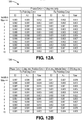
- Figure 12A illustrates a table 1200 showing the pointing error of the transmitter antenna 110A and the pointing error of the receiver antenna 110B with a phase measurement error of 2 degrees root-mean-square (RMS) only, according to an implementation.
- the pointing error may include an elevation error, an azimuth error, and a yaw error.
- the values in the table 1200 may be determined during a plurality of iterations (e.g., ten) with a phase measurement error of, for example, 2 degrees root-mean-square only. Each iteration has a different fixed pointing error and spacecraft longitude. Within each iteration, a plurality (e.g., ten) measurements may be performed with random phase error on each phase array element.
- the top row represents the iteration maximum, which refers to the maximum residual pointing error of the simulation iterations.
- the maximum residual pointing error is below an illustrative pointing error target/goal, which, in this example, is 0.04 degrees elevation, 0.04 degrees azimuth, and 0.06 degrees yaw.
- Figure 12B illustrates a table 1250 showing the pointing error of the transmitter antenna 110A and the pointing error of the receiver antenna 110B with a phase measurement error of 6 degrees RMS, a position knowledge error of 50 meters RMS, and an attitude knowledge error of 0.005 degrees RMS, according to an implementation.
- the pointing error may include an elevation error, an azimuth error, and a yaw error.
- the values in the table 1250 may be determined during a plurality of iterations (e.g., ten). Each iteration has a different fixed pointing error, spacecraft longitude, and spacecraft telemetry error (e.g., location and attitude). Within each iteration, a plurality (e.g., ten) measurements are performed with random phase error on each element.
- the top row represents the iteration maximum. As may be seen in the table 1250, the maximum residual pointing error is below the pointing error target/goal, which, in this example, is 0.04 degrees elevation, 0.04 degrees azimuth, and 0.06 degrees yaw.
- Figure 13A illustrates a graph 1300 showing the residual pointing error (in degrees) versus gateway latitude (in degrees) for the transmitter antenna 110A, according to an implementation.
- Figure 13B illustrates a graph 1350 showing the residual pointing error (in degrees) versus gateway latitude (in degrees) for the receiver antenna 110B, according to an implementation.
- a parametric sweep of the gateway latitude was run from 0 degrees to 55 degrees in steps of 5 degrees. There were 100 iterations per step.
- a first spacecraft longitude offset was maintained at a random value between 7 degrees and 12 degrees
- a second spacecraft longitude offset was maintained at a random value between -7 degrees and -12 degrees.
- the residual pointing error target/goals e.g., 0.04 degrees elevation, 0.04 degrees azimuth, and 0.06 degrees yaw
- the target/goal may be achieved for a wide variety of gateway latitude locations.
- the method 500 may also include transmitting a signal from the computing system 1400 at the gateway to the spacecraft 100 that causes the spacecraft 100 to move to reduce the pointing error, as at 522.
- the signal may cause the spacecraft 100 to physically roll, pitch, and/or yaw to reduce the pointing error.
- the signal may be received by the DSP 124 on the spacecraft 100, and the DSP 124 may then re-point the phase array elements electronically (e.g., not physically) to adjust for (reduce) the pointing error.
- the signal may be based upon the intersection(s) at 520.
- the gateway location has a latitude of 21.66 degrees and a longitude of -158.05 degrees.
- the spacecraft longitude offset 1 is random between 7 degrees and 12 degrees
- the spacecraft longitude offset 2 is random between -7 degrees and -12 degrees.
- the yaw rotation is 0.36 degree per degree of longitude.
- the phase measurements are performed using the same portion of the method 500 described above.
- the simulated measurement phase variation is 2 degrees RMS.
- the simulation was also run with 6 degrees RMS.
- the transmitter frequency was 18.95 GHz, and the receiver frequency was 28.75 GHz.
- Ten measurements were taken at each spacecraft location. As described above, this may be repeated multiple (e.g., 4) times throughout the day at various drive levels to average out diurnal and/or temperature errors.
- the spacecraft state vector telemetry may provide spacecraft location and attitude, which may be used to compensate the measurements.
- FIG. 14 illustrates a schematic view of a computing system 1400 for performing at least a portion of the method 500, according to an implementation.
- the computing system 1400 may include a computer or computer system 1401A, which may be an individual computer system 1401A or an arrangement of distributed computer systems.
- the computer system 1401A includes one or more analysis modules 1402 that are configured to perform various tasks according to some implementations, such as one or more methods disclosed herein. To perform these various tasks, the analysis module 1402 executes independently, or in coordination with, one or more processors 1404, which is (or are) connected to one or more storage media 1406.
- the processor(s) 1404 is (or are) also connected to a network interface 1407 to allow the computer system 1401A to communicate over a data network 1409 with one or more additional computer systems and/or computing systems, such as 1401B, 1401C, and/or 1401D (note that computer systems 1401B, 1401C and/or 1401D may or may not share the same architecture as computer system 1401A, and may be located in different physical locations, e.g., computer systems 1401A and 1401B may be located in a processing facility, while in communication with one or more computer systems such as 1401C and/or 1401D that are located in one or more data centers, and/or located in varying countries on different continents).
- a processor may include a microprocessor, microcontroller, processor module or subsystem, programmable integrated circuit, programmable gate array, or another control or computing device.
- the storage media 1406 may be implemented as one or more computer-readable or machine-readable storage media. Note that while in the example implementation of Figure 14 storage media 1406 is depicted as within computer system 1401A, in some implementations, storage media 1406 may be distributed within and/or across multiple internal and/or external enclosures of computing system 1401A and/or additional computing systems.
- Storage media 1406 may include one or more different forms of memory including semiconductor memory devices such as dynamic or static random access memories (DRAMs or SRAMs), erasable and programmable read-only memories (EPROMs), electrically erasable and programmable read-only memories (EEPROMs) and flash memories, magnetic disks such as fixed, floppy and removable disks, other magnetic media including tape, optical media such as compact disks (CDs) or digital video disks (DVDs), BLURAY® disks, or other types of optical storage, or other types of storage devices.
- semiconductor memory devices such as dynamic or static random access memories (DRAMs or SRAMs), erasable and programmable read-only memories (EPROMs), electrically erasable and programmable read-only memories (EEPROMs) and flash memories
- magnetic disks such as fixed, floppy and removable disks, other magnetic media including tape
- optical media such as compact disks (CDs) or digital video disks (DVDs)
- DVDs digital video disks
- Such computer-readable or machine-readable storage medium or media is (are) considered to be part of an article (or article of manufacture).
- An article or article of manufacture may refer to any manufactured single component or multiple components.
- the storage medium or media may be located either in the machine running the machine-readable instructions, or located at a remote site from which machine-readable instructions may be downloaded over a network for execution.
- computing system 1400 contains one or more antenna calibration module(s) 1408 that may perform at least a portion of the method 500 disclosed herein. It should be appreciated that computing system 1400 is merely one example of a computing system, and that computing system 1400 may have more or fewer components than shown, may combine additional components not depicted in the example implementation of Figure 14 , and/or computing system 1400 may have a different configuration or arrangement of the components depicted in Figure 14 .
- the various components shown in Figure 14 may be implemented in hardware, software, or a combination of both hardware and software, including one or more signal processing and/or application specific integrated circuits.
- steps in the processing methods described herein may be implemented by running one or more functional modules in information processing apparatus such as general purpose processors or application specific chips, such as ASICs, FPGAs, PLDs, or other appropriate devices.
- ASICs general purpose processors or application specific chips, such as ASICs, FPGAs, PLDs, or other appropriate devices.
- Computational interpretations, models, and/or other interpretation aids may be refined in an iterative fashion; this concept is applicable to the methods discussed herein. This may include use of feedback loops executed on an algorithmic basis, such as at a computing device (e.g., computing system 1400, Figure 14 ), and/or through manual control by a user who may make determinations regarding whether a given step, action, template, model, or set of curves has become sufficiently accurate for the evaluation of the subsurface three-dimensional geologic formation under consideration.
- a computing device e.g., computing system 1400, Figure 14
- the term "at least one of A and B" with respect to a listing of items such as, for example, A and B, means A alone, B alone, or A and B.
- Those skilled in the art will recognize that these and other variations are possible.
- the terms “including,” “includes,” “having,” “has,” “with,” or variants thereof are used in either the detailed description and the claims, such terms are intended to be inclusive in a manner similar to the term “comprising.”
- the term “about” indicates that the value listed may be somewhat altered, as long as the alteration does not result in nonconformance of the process or structure to the intended purpose described herein.
- “exemplary” indicates the description is used as an example, rather than implying that it is an ideal.
Landscapes
- Engineering & Computer Science (AREA)
- Physics & Mathematics (AREA)
- Astronomy & Astrophysics (AREA)
- General Physics & Mathematics (AREA)
- Aviation & Aerospace Engineering (AREA)
- Computer Networks & Wireless Communication (AREA)
- Signal Processing (AREA)
- Remote Sensing (AREA)
- Electromagnetism (AREA)
- Variable-Direction Aerials And Aerial Arrays (AREA)
- Radar Systems Or Details Thereof (AREA)
Applications Claiming Priority (1)
| Application Number | Priority Date | Filing Date | Title |
|---|---|---|---|
| US16/734,939 US20210210841A1 (en) | 2020-01-06 | 2020-01-06 | System and method for calibrating an antenna |
Publications (2)
| Publication Number | Publication Date |
|---|---|
| EP3846358A1 true EP3846358A1 (fr) | 2021-07-07 |
| EP3846358B1 EP3846358B1 (fr) | 2023-09-06 |
Family
ID=73855691
Family Applications (1)
| Application Number | Title | Priority Date | Filing Date |
|---|---|---|---|
| EP20215317.7A Active EP3846358B1 (fr) | 2020-01-06 | 2020-12-18 | Système et procédé d'étalonnage d'une antenne |
Country Status (3)
| Country | Link |
|---|---|
| US (1) | US20210210841A1 (fr) |
| EP (1) | EP3846358B1 (fr) |
| CN (1) | CN113078968A (fr) |
Citations (3)
| Publication number | Priority date | Publication date | Assignee | Title |
|---|---|---|---|---|
| WO2008048807A2 (fr) * | 2006-10-06 | 2008-04-24 | Viasat, Inc. | Calibrage aller et retour pour formation de faisceau au sol |
| WO2015123623A1 (fr) * | 2014-02-17 | 2015-08-20 | Ubiqomm | Système d'accès à large bande par le biais de plates-formes à drones/uav |
| EP3279694A1 (fr) * | 2016-08-01 | 2018-02-07 | Space Systems/Loral, LLC | Étalonnage de satellite |
-
2020
- 2020-01-06 US US16/734,939 patent/US20210210841A1/en not_active Abandoned
- 2020-12-18 EP EP20215317.7A patent/EP3846358B1/fr active Active
-
2021
- 2021-01-06 CN CN202110011416.3A patent/CN113078968A/zh active Pending
Patent Citations (3)
| Publication number | Priority date | Publication date | Assignee | Title |
|---|---|---|---|---|
| WO2008048807A2 (fr) * | 2006-10-06 | 2008-04-24 | Viasat, Inc. | Calibrage aller et retour pour formation de faisceau au sol |
| WO2015123623A1 (fr) * | 2014-02-17 | 2015-08-20 | Ubiqomm | Système d'accès à large bande par le biais de plates-formes à drones/uav |
| EP3279694A1 (fr) * | 2016-08-01 | 2018-02-07 | Space Systems/Loral, LLC | Étalonnage de satellite |
Also Published As
| Publication number | Publication date |
|---|---|
| CN113078968A (zh) | 2021-07-06 |
| EP3846358B1 (fr) | 2023-09-06 |
| US20210210841A1 (en) | 2021-07-08 |
Similar Documents
| Publication | Publication Date | Title |
|---|---|---|
| EP2449626B1 (fr) | Antenne réseau à commande de phase conformée à auto-étalonnage | |
| CN104678408B (zh) | 星载导航接收机授时方法和授时型星载导航接收机以及星载导航应用系统 | |
| CN102753991B (zh) | 短基线和超短基线相位图 | |
| US8717226B2 (en) | Method for processing signals of an airborne radar with correction of the error in the radar beam pointing angle and corresponding device | |
| EP1828803A1 (fr) | Systeme et technique d'etalonnage de reseaux de radars | |
| US6806837B1 (en) | Deep depression angle calibration of airborne direction finding arrays | |
| CN110058204B (zh) | 一种基于方向图匹配的星载天线波束中心定标方法 | |
| CN112660419B (zh) | 一种重力卫星质心在轨标定方法及系统 | |
| CN112461262A (zh) | 一种校正三轴磁强计误差的装置和方法 | |
| CN110146924A (zh) | 基于水波初至偏振方位的海底地震仪位置及方位反演方法 | |
| CN108562305A (zh) | 一种惯性/天文深组合导航系统安装误差五位置快速粗标定方法 | |
| CN110244367B (zh) | 一种基于地面多基站的ztem系统姿态补偿方法 | |
| EP3846358A1 (fr) | Système et procédé d'étalonnage d'une antenne | |
| CN114035205A (zh) | Gnss-r海面测高精度与沿轨空间分辨率重构方法和系统 | |
| CN105842259A (zh) | 星载盐度计冷空外定标方法和装置 | |
| CN109412710B (zh) | 一种天线传输性能评估方法和装置 | |
| Zink et al. | Calibration of the Interferometric X-SAR System on SRTM | |
| CN111337955B (zh) | 星载单星测频无源定位接收机试验方法 | |
| CN112859053A (zh) | 一种标定激光雷达时变参数的方法及系统 | |
| US6768455B1 (en) | Calibration probe motion detector | |
| RU2751121C1 (ru) | Способ определения формы амплитудной диаграммы направленности антенной системы навигационного космического аппарата | |
| Wang et al. | Single-antenna attitude determination for Fedsat with improved antenna gain patterns | |
| Baron et al. | ICC experiences on Inertial/GPS sensor orientation | |
| Mironov et al. | The multiposition passive satellite system for the terrestrial radiation sources monitoring | |
| Garrick | Investigation of models and estimation techniques for GPS attitude determination |
Legal Events
| Date | Code | Title | Description |
|---|---|---|---|
| PUAI | Public reference made under article 153(3) epc to a published international application that has entered the european phase |
Free format text: ORIGINAL CODE: 0009012 |
|
| STAA | Information on the status of an ep patent application or granted ep patent |
Free format text: STATUS: THE APPLICATION HAS BEEN PUBLISHED |
|
| AK | Designated contracting states |
Kind code of ref document: A1 Designated state(s): AL AT BE BG CH CY CZ DE DK EE ES FI FR GB GR HR HU IE IS IT LI LT LU LV MC MK MT NL NO PL PT RO RS SE SI SK SM TR |
|
| STAA | Information on the status of an ep patent application or granted ep patent |
Free format text: STATUS: REQUEST FOR EXAMINATION WAS MADE |
|
| 17P | Request for examination filed |
Effective date: 20211116 |
|
| RBV | Designated contracting states (corrected) |
Designated state(s): AL AT BE BG CH CY CZ DE DK EE ES FI FR GB GR HR HU IE IS IT LI LT LU LV MC MK MT NL NO PL PT RO RS SE SI SK SM TR |
|
| RAP3 | Party data changed (applicant data changed or rights of an application transferred) |
Owner name: THE BOEING COMPANY |
|
| GRAP | Despatch of communication of intention to grant a patent |
Free format text: ORIGINAL CODE: EPIDOSNIGR1 |
|
| STAA | Information on the status of an ep patent application or granted ep patent |
Free format text: STATUS: GRANT OF PATENT IS INTENDED |
|
| INTG | Intention to grant announced |
Effective date: 20230329 |
|
| GRAS | Grant fee paid |
Free format text: ORIGINAL CODE: EPIDOSNIGR3 |
|
| GRAA | (expected) grant |
Free format text: ORIGINAL CODE: 0009210 |
|
| STAA | Information on the status of an ep patent application or granted ep patent |
Free format text: STATUS: THE PATENT HAS BEEN GRANTED |
|
| AK | Designated contracting states |
Kind code of ref document: B1 Designated state(s): AL AT BE BG CH CY CZ DE DK EE ES FI FR GB GR HR HU IE IS IT LI LT LU LV MC MK MT NL NO PL PT RO RS SE SI SK SM TR |
|
| P01 | Opt-out of the competence of the unified patent court (upc) registered |
Effective date: 20230731 |
|
| REG | Reference to a national code |
Ref country code: GB Ref legal event code: FG4D |
|
| REG | Reference to a national code |
Ref country code: CH Ref legal event code: EP |
|
| REG | Reference to a national code |
Ref country code: IE Ref legal event code: FG4D |
|
| REG | Reference to a national code |
Ref country code: DE Ref legal event code: R096 Ref document number: 602020017162 Country of ref document: DE |
|
| REG | Reference to a national code |
Ref country code: LT Ref legal event code: MG9D |
|
| REG | Reference to a national code |
Ref country code: NL Ref legal event code: MP Effective date: 20230906 |
|
| PG25 | Lapsed in a contracting state [announced via postgrant information from national office to epo] |
Ref country code: GR Free format text: LAPSE BECAUSE OF FAILURE TO SUBMIT A TRANSLATION OF THE DESCRIPTION OR TO PAY THE FEE WITHIN THE PRESCRIBED TIME-LIMIT Effective date: 20231207 |
|
| PG25 | Lapsed in a contracting state [announced via postgrant information from national office to epo] |
Ref country code: SE Free format text: LAPSE BECAUSE OF FAILURE TO SUBMIT A TRANSLATION OF THE DESCRIPTION OR TO PAY THE FEE WITHIN THE PRESCRIBED TIME-LIMIT Effective date: 20230906 Ref country code: RS Free format text: LAPSE BECAUSE OF FAILURE TO SUBMIT A TRANSLATION OF THE DESCRIPTION OR TO PAY THE FEE WITHIN THE PRESCRIBED TIME-LIMIT Effective date: 20230906 Ref country code: NO Free format text: LAPSE BECAUSE OF FAILURE TO SUBMIT A TRANSLATION OF THE DESCRIPTION OR TO PAY THE FEE WITHIN THE PRESCRIBED TIME-LIMIT Effective date: 20231206 Ref country code: LV Free format text: LAPSE BECAUSE OF FAILURE TO SUBMIT A TRANSLATION OF THE DESCRIPTION OR TO PAY THE FEE WITHIN THE PRESCRIBED TIME-LIMIT Effective date: 20230906 Ref country code: LT Free format text: LAPSE BECAUSE OF FAILURE TO SUBMIT A TRANSLATION OF THE DESCRIPTION OR TO PAY THE FEE WITHIN THE PRESCRIBED TIME-LIMIT Effective date: 20230906 Ref country code: HR Free format text: LAPSE BECAUSE OF FAILURE TO SUBMIT A TRANSLATION OF THE DESCRIPTION OR TO PAY THE FEE WITHIN THE PRESCRIBED TIME-LIMIT Effective date: 20230906 Ref country code: GR Free format text: LAPSE BECAUSE OF FAILURE TO SUBMIT A TRANSLATION OF THE DESCRIPTION OR TO PAY THE FEE WITHIN THE PRESCRIBED TIME-LIMIT Effective date: 20231207 Ref country code: FI Free format text: LAPSE BECAUSE OF FAILURE TO SUBMIT A TRANSLATION OF THE DESCRIPTION OR TO PAY THE FEE WITHIN THE PRESCRIBED TIME-LIMIT Effective date: 20230906 |
|
| PGFP | Annual fee paid to national office [announced via postgrant information from national office to epo] |
Ref country code: FR Payment date: 20231227 Year of fee payment: 4 |
|
| REG | Reference to a national code |
Ref country code: AT Ref legal event code: MK05 Ref document number: 1609894 Country of ref document: AT Kind code of ref document: T Effective date: 20230906 |
|
| PG25 | Lapsed in a contracting state [announced via postgrant information from national office to epo] |
Ref country code: NL Free format text: LAPSE BECAUSE OF FAILURE TO SUBMIT A TRANSLATION OF THE DESCRIPTION OR TO PAY THE FEE WITHIN THE PRESCRIBED TIME-LIMIT Effective date: 20230906 |
|
| PG25 | Lapsed in a contracting state [announced via postgrant information from national office to epo] |
Ref country code: IS Free format text: LAPSE BECAUSE OF FAILURE TO SUBMIT A TRANSLATION OF THE DESCRIPTION OR TO PAY THE FEE WITHIN THE PRESCRIBED TIME-LIMIT Effective date: 20240106 |
|
| PG25 | Lapsed in a contracting state [announced via postgrant information from national office to epo] |
Ref country code: AT Free format text: LAPSE BECAUSE OF FAILURE TO SUBMIT A TRANSLATION OF THE DESCRIPTION OR TO PAY THE FEE WITHIN THE PRESCRIBED TIME-LIMIT Effective date: 20230906 |
|
| PG25 | Lapsed in a contracting state [announced via postgrant information from national office to epo] |
Ref country code: ES Free format text: LAPSE BECAUSE OF FAILURE TO SUBMIT A TRANSLATION OF THE DESCRIPTION OR TO PAY THE FEE WITHIN THE PRESCRIBED TIME-LIMIT Effective date: 20230906 |
|
| PG25 | Lapsed in a contracting state [announced via postgrant information from national office to epo] |
Ref country code: SM Free format text: LAPSE BECAUSE OF FAILURE TO SUBMIT A TRANSLATION OF THE DESCRIPTION OR TO PAY THE FEE WITHIN THE PRESCRIBED TIME-LIMIT Effective date: 20230906 Ref country code: RO Free format text: LAPSE BECAUSE OF FAILURE TO SUBMIT A TRANSLATION OF THE DESCRIPTION OR TO PAY THE FEE WITHIN THE PRESCRIBED TIME-LIMIT Effective date: 20230906 Ref country code: IS Free format text: LAPSE BECAUSE OF FAILURE TO SUBMIT A TRANSLATION OF THE DESCRIPTION OR TO PAY THE FEE WITHIN THE PRESCRIBED TIME-LIMIT Effective date: 20240106 Ref country code: ES Free format text: LAPSE BECAUSE OF FAILURE TO SUBMIT A TRANSLATION OF THE DESCRIPTION OR TO PAY THE FEE WITHIN THE PRESCRIBED TIME-LIMIT Effective date: 20230906 Ref country code: EE Free format text: LAPSE BECAUSE OF FAILURE TO SUBMIT A TRANSLATION OF THE DESCRIPTION OR TO PAY THE FEE WITHIN THE PRESCRIBED TIME-LIMIT Effective date: 20230906 Ref country code: CZ Free format text: LAPSE BECAUSE OF FAILURE TO SUBMIT A TRANSLATION OF THE DESCRIPTION OR TO PAY THE FEE WITHIN THE PRESCRIBED TIME-LIMIT Effective date: 20230906 Ref country code: AT Free format text: LAPSE BECAUSE OF FAILURE TO SUBMIT A TRANSLATION OF THE DESCRIPTION OR TO PAY THE FEE WITHIN THE PRESCRIBED TIME-LIMIT Effective date: 20230906 Ref country code: SK Free format text: LAPSE BECAUSE OF FAILURE TO SUBMIT A TRANSLATION OF THE DESCRIPTION OR TO PAY THE FEE WITHIN THE PRESCRIBED TIME-LIMIT Effective date: 20230906 Ref country code: PT Free format text: LAPSE BECAUSE OF FAILURE TO SUBMIT A TRANSLATION OF THE DESCRIPTION OR TO PAY THE FEE WITHIN THE PRESCRIBED TIME-LIMIT Effective date: 20240108 |
|
| PGFP | Annual fee paid to national office [announced via postgrant information from national office to epo] |
Ref country code: DE Payment date: 20231229 Year of fee payment: 4 |
|
| PG25 | Lapsed in a contracting state [announced via postgrant information from national office to epo] |
Ref country code: PL Free format text: LAPSE BECAUSE OF FAILURE TO SUBMIT A TRANSLATION OF THE DESCRIPTION OR TO PAY THE FEE WITHIN THE PRESCRIBED TIME-LIMIT Effective date: 20230906 Ref country code: IT Free format text: LAPSE BECAUSE OF FAILURE TO SUBMIT A TRANSLATION OF THE DESCRIPTION OR TO PAY THE FEE WITHIN THE PRESCRIBED TIME-LIMIT Effective date: 20230906 |
|
| REG | Reference to a national code |
Ref country code: DE Ref legal event code: R097 Ref document number: 602020017162 Country of ref document: DE |
|
| PG25 | Lapsed in a contracting state [announced via postgrant information from national office to epo] |
Ref country code: DK Free format text: LAPSE BECAUSE OF FAILURE TO SUBMIT A TRANSLATION OF THE DESCRIPTION OR TO PAY THE FEE WITHIN THE PRESCRIBED TIME-LIMIT Effective date: 20230906 |
|
| PLBE | No opposition filed within time limit |
Free format text: ORIGINAL CODE: 0009261 |
|
| STAA | Information on the status of an ep patent application or granted ep patent |
Free format text: STATUS: NO OPPOSITION FILED WITHIN TIME LIMIT |
|
| PG25 | Lapsed in a contracting state [announced via postgrant information from national office to epo] |
Ref country code: DK Free format text: LAPSE BECAUSE OF FAILURE TO SUBMIT A TRANSLATION OF THE DESCRIPTION OR TO PAY THE FEE WITHIN THE PRESCRIBED TIME-LIMIT Effective date: 20230906 Ref country code: SI Free format text: LAPSE BECAUSE OF FAILURE TO SUBMIT A TRANSLATION OF THE DESCRIPTION OR TO PAY THE FEE WITHIN THE PRESCRIBED TIME-LIMIT Effective date: 20230906 |
|
| REG | Reference to a national code |
Ref country code: CH Ref legal event code: PL |
|
| 26N | No opposition filed |
Effective date: 20240607 |
|
| PG25 | Lapsed in a contracting state [announced via postgrant information from national office to epo] |
Ref country code: LU Free format text: LAPSE BECAUSE OF NON-PAYMENT OF DUE FEES Effective date: 20231218 |
|
| PG25 | Lapsed in a contracting state [announced via postgrant information from national office to epo] |
Ref country code: MC Free format text: LAPSE BECAUSE OF FAILURE TO SUBMIT A TRANSLATION OF THE DESCRIPTION OR TO PAY THE FEE WITHIN THE PRESCRIBED TIME-LIMIT Effective date: 20230906 |
|
| REG | Reference to a national code |
Ref country code: BE Ref legal event code: MM Effective date: 20231231 |
|
| PG25 | Lapsed in a contracting state [announced via postgrant information from national office to epo] |
Ref country code: MC Free format text: LAPSE BECAUSE OF FAILURE TO SUBMIT A TRANSLATION OF THE DESCRIPTION OR TO PAY THE FEE WITHIN THE PRESCRIBED TIME-LIMIT Effective date: 20230906 Ref country code: LU Free format text: LAPSE BECAUSE OF NON-PAYMENT OF DUE FEES Effective date: 20231218 |