EP3846321A1 - Kühlvorrichtung und motorwechselrichter - Google Patents
Kühlvorrichtung und motorwechselrichter Download PDFInfo
- Publication number
- EP3846321A1 EP3846321A1 EP20212108.3A EP20212108A EP3846321A1 EP 3846321 A1 EP3846321 A1 EP 3846321A1 EP 20212108 A EP20212108 A EP 20212108A EP 3846321 A1 EP3846321 A1 EP 3846321A1
- Authority
- EP
- European Patent Office
- Prior art keywords
- cooling
- contact surface
- cooling structure
- electric machine
- power module
- Prior art date
- Legal status (The legal status is an assumption and is not a legal conclusion. Google has not performed a legal analysis and makes no representation as to the accuracy of the status listed.)
- Granted
Links
- 238000001816 cooling Methods 0.000 title claims abstract description 143
- 239000007787 solid Substances 0.000 claims abstract description 31
- 229910052751 metal Inorganic materials 0.000 claims abstract description 28
- 239000002184 metal Substances 0.000 claims abstract description 28
- 239000000110 cooling liquid Substances 0.000 claims abstract description 5
- 230000035939 shock Effects 0.000 claims description 2
- 239000007788 liquid Substances 0.000 description 14
- 238000003754 machining Methods 0.000 description 6
- 238000005192 partition Methods 0.000 description 6
- 238000009499 grossing Methods 0.000 description 5
- 239000000463 material Substances 0.000 description 4
- XEEYBQQBJWHFJM-UHFFFAOYSA-N Iron Chemical compound [Fe] XEEYBQQBJWHFJM-UHFFFAOYSA-N 0.000 description 2
- XUIMIQQOPSSXEZ-UHFFFAOYSA-N Silicon Chemical compound [Si] XUIMIQQOPSSXEZ-UHFFFAOYSA-N 0.000 description 2
- 229910000831 Steel Inorganic materials 0.000 description 2
- 239000000654 additive Substances 0.000 description 2
- 230000000996 additive effect Effects 0.000 description 2
- 229910052782 aluminium Inorganic materials 0.000 description 2
- XAGFODPZIPBFFR-UHFFFAOYSA-N aluminium Chemical compound [Al] XAGFODPZIPBFFR-UHFFFAOYSA-N 0.000 description 2
- 238000000429 assembly Methods 0.000 description 2
- 230000000295 complement effect Effects 0.000 description 2
- 238000010586 diagram Methods 0.000 description 2
- 238000004519 manufacturing process Methods 0.000 description 2
- 239000010959 steel Substances 0.000 description 2
- 238000010146 3D printing Methods 0.000 description 1
- RYGMFSIKBFXOCR-UHFFFAOYSA-N Copper Chemical compound [Cu] RYGMFSIKBFXOCR-UHFFFAOYSA-N 0.000 description 1
- 230000001133 acceleration Effects 0.000 description 1
- 239000003990 capacitor Substances 0.000 description 1
- 230000015556 catabolic process Effects 0.000 description 1
- 229910052802 copper Inorganic materials 0.000 description 1
- 239000010949 copper Substances 0.000 description 1
- 238000001914 filtration Methods 0.000 description 1
- 239000012530 fluid Substances 0.000 description 1
- 230000005484 gravity Effects 0.000 description 1
- 238000010438 heat treatment Methods 0.000 description 1
- 229910052742 iron Inorganic materials 0.000 description 1
- 230000007257 malfunction Effects 0.000 description 1
- 238000000465 moulding Methods 0.000 description 1
- 239000003921 oil Substances 0.000 description 1
- 230000001681 protective effect Effects 0.000 description 1
- 238000007789 sealing Methods 0.000 description 1
- 239000004065 semiconductor Substances 0.000 description 1
- 230000035945 sensitivity Effects 0.000 description 1
- 229910052710 silicon Inorganic materials 0.000 description 1
- 239000010703 silicon Substances 0.000 description 1
- HBMJWWWQQXIZIP-UHFFFAOYSA-N silicon carbide Chemical compound [Si+]#[C-] HBMJWWWQQXIZIP-UHFFFAOYSA-N 0.000 description 1
- 229910010271 silicon carbide Inorganic materials 0.000 description 1
- 239000007858 starting material Substances 0.000 description 1
- 230000003068 static effect Effects 0.000 description 1
- XLYOFNOQVPJJNP-UHFFFAOYSA-N water Substances O XLYOFNOQVPJJNP-UHFFFAOYSA-N 0.000 description 1
Images


Classifications
-
- H—ELECTRICITY
- H02—GENERATION; CONVERSION OR DISTRIBUTION OF ELECTRIC POWER
- H02K—DYNAMO-ELECTRIC MACHINES
- H02K5/00—Casings; Enclosures; Supports
- H02K5/04—Casings or enclosures characterised by the shape, form or construction thereof
- H02K5/20—Casings or enclosures characterised by the shape, form or construction thereof with channels or ducts for flow of cooling medium
- H02K5/203—Casings or enclosures characterised by the shape, form or construction thereof with channels or ducts for flow of cooling medium specially adapted for liquids, e.g. cooling jackets
-
- H—ELECTRICITY
- H02—GENERATION; CONVERSION OR DISTRIBUTION OF ELECTRIC POWER
- H02K—DYNAMO-ELECTRIC MACHINES
- H02K11/00—Structural association of dynamo-electric machines with electric components or with devices for shielding, monitoring or protection
- H02K11/30—Structural association with control circuits or drive circuits
- H02K11/33—Drive circuits, e.g. power electronics
-
- H—ELECTRICITY
- H02—GENERATION; CONVERSION OR DISTRIBUTION OF ELECTRIC POWER
- H02K—DYNAMO-ELECTRIC MACHINES
- H02K9/00—Arrangements for cooling or ventilating
- H02K9/22—Arrangements for cooling or ventilating by solid heat conducting material embedded in, or arranged in contact with, the stator or rotor, e.g. heat bridges
Definitions
- a motor-variator comprises a rotating electrical machine capable of operating in a motor mode in which it transforms electrical energy into mechanical energy and thus drives a rotating shaft, and an electronic speed variator comprising power components and making it possible to vary an electric power supply signal for the rotating electric machine operating in motor mode so as to vary a speed of rotation of the motor and / or a torque delivered by the motor.
- the invention applies in particular to motor-drives capable of starting a turbine engine of an aircraft.
- the invention relates more particularly to the cooling of motor-drives. Indeed, the active parts of the rotating electrical machine (rotor and stator) as well as the electronic power components of the electronic speed variator generate heat that it is necessary to dissipate to avoid a malfunction of these elements and more so. overall, of the motor-variator.
- the rotating electrical machine and the variable speed drive form separate sub-assemblies intended to be electrically connected.
- Each of these sub-assemblies is equipped with a dedicated liquid cooling device.
- This type of motor-variator has a high mass.
- mass saving is a fundamental problem.
- An aim of the invention is to limit at least one of the aforementioned drawbacks.
- the invention relates to a cooling structure intended to cool a rotating electrical machine and an assembly of at least one electronic power module of an electronic speed variator making it possible to make varying an electric power supply signal to the rotating electric machine so as to vary a speed of rotation of a shaft driven by the electric machine and / or a torque supplied by the electric machine, the power module comprising a power component , the cooling structure comprising a solid metal body having a generally tubular shape delimited radially by a first contact surface intended to completely radially surround the electrical machine and to be in physical contact with the electrical machine and by a second contact surface completely radially surrounding the first contact surface and intended to be in physical contact with a first power module of the set of at least one power module so as to be able to cool the electrical machine and the power module, the cooling structure comprising an assembly of at least one cooling channel formed in the solid metal body, at a distance from the first contact surface and from the second contact surface, in which a cooling liquid is intended to circulate.
- the metal body is in one piece.
- the cooling channels are located at any point at a distance from the first contact surface DI and from the second contact surface SE.
- the second contact surface comprises a set of at least one planar face.
- a first cooling channel of the assembly of at least one cooling channel is interposed radially between the first flat face and the contact surface.
- the second contact surface has a generally parallelepipedal shape.
- the cooling structure is structural.
- the cooling structure is configured to have impact resistance, on each of the three axes of an orthogonal coordinate system, up to a limit greater than or equal to 20 g for a minimum impact duration of 11 ms.
- the assembly of at least one cooling channel comprises several cooling channels configured so as to be capable of being connected in parallel.
- the invention relates to a motor-variator comprising a cooling structure according to the invention; the rotating electric machine and the electronic speed variator.
- the first contact surface completely radially surrounds the electric machine and is in physical contact with the electric machine and the second contact surface is physical contact with the first power module so as to be able to cool the electric machine and the module. power.
- the electrical machine comprises a rotor, a stator and a casing surrounding the stator and the rotor, the metallic body being in direct physical contact with the casing.
- the electrical machine is forced into a tunnel delimited by the metal body.
- the invention relates to a motor-variator MV and a cooling structure of such a motor-variator.
- FIG. 1 A functional diagram of a non-limiting example of a motor-drive is shown in figure 1 .
- the invention relates in particular to MV motor-drives which are starter generators for aircraft turbines. These MV motor-drives are able to operate as a motor for starting a turbine engine of an airplane and, as a generator for electrically supplying an electrical network.
- the MV motor-variator comprises an electric motor or rotating electric machine ME and an electronic speed variator VE making it possible to vary an alternating or direct supply signal of the electric machine so as to vary a rotational speed of the electric machine when the latter operates as a motor and / or so as to vary a torque supplied by the electric machine when the latter operates as a motor.
- the VE electronic speed controller shown in figure 1 is intended to vary an AC supply voltage of the electric machine ME. It comprises a rectifier RE comprising, for example, a diode bridge.
- the electronic variable speed drive includes an AC smoothing capability (in the case of a voltage source drive). This smoothing capacity can be replaced by a smoothing coil (in the case of a drive in current source).
- the electronic speed variator also includes an ON inverter making it possible to deliver an alternating current from a direct current delivered at the output of the smoothing capability (or, alternatively, the smoothing coil).
- the inverter includes controllable switches.
- the VE drive also includes a COM control module for controlling the controllable switches.
- the drive does not include an RE rectifier when supplied with a DC voltage.
- the VE drive includes a set of electronic power components including controllable switches from the ON inverter.
- power electronic component is understood to mean a component capable of being passed through by alternating or direct currents of several tens of amperes without being damaged.
- the VE variable speed drive comprises, for example, insulated gate bipolar transistors or IGBTs (acronym of the English expression “Insulated Gate Bipolar Transistors”) and / or MOS transistors (acronym of the expression “Metal Oxyde Silicium ").
- the VE variable speed drive can also include semiconductor diodes made, for example, from silicon or silicon carbide.
- the electronic speed variator VE comprises a set of power modules each comprising a set of at least one power component taken from among the power components of the electronic speed variator.
- FIG 2 schematically shows, in exploded view, the main elements necessary for understanding the invention, of a motor-variator MV according to the invention, namely, a cooling structure SR according to a first embodiment of the invention, a rotating electrical machine ME and power modules MP1, MP2, MP3 of the electronic speed variator VE of the motor-variator MV.
- Each motor-variator comprises a set of at least power components taken from the power components of the electronic speed variator VE.
- the motor-drive MV comprises an electric machine ME which is intended to rotate a motor shaft A around a rotation axis I.
- the SR cooling structure according to the invention comprises a solid metal body CM.
- the solid metal body CM has a generally tubular shape formed around an x axis.
- the solid metal body CM is radially delimited by a first contact surface SI completely surrounding, radially, the x axis and by a second contact surface SE completely surrounding, radially, the first contact surface SI.
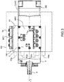
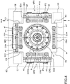
- the second contact surface SE is intended to be in physical contact with the power modules MP1, MP2, MP3 so as to be able to cool the power modules MP1, MP2, MP3, as can be seen in figure 3 and in figure 4 showing, in side view and in front view respectively, the elements of figure 3 assembled.
- the first contact surface SI is intended to completely radially surround the electric machine ME and to be in physical contact with the electric machine ME so as to be able to cool the electric machine ME, as can be seen in figure 4 .
- the metal body CM is interposed radially between the electric machine ME and the power modules MP1, MP2, MP3.
- the radial character is defined with respect to the x axis.
- the x axis is perpendicular to the plane of the figure 4 and parallel to the plane of the figure 3 .
- the solid metal body CM is delimited, along the x axis, by two transverse faces ST1 and ST2 of which only the surface ST1 is visible in figure 1 , extending substantially perpendicular to the x axis.
- the cooling structure CM also comprises a set of cooling channels CR1, CR2, CR3, CR4 formed in the metallic body CM, between the first contact surface and the second contact surface, at a distance from the first surface. contact SI and the second contact surface SE, and in which a cooling liquid is intended to circulate.
- the CM cooling structure can be compared to a tubular cold plate.
- the invention therefore makes it possible, thanks to a single cooling structure SR, to ensure simultaneous liquid cooling of the power modules MP1, MP2, MP3 and of the electric machine ME.
- This solution using an SR cooling structure, common to the power modules MP1, MP2, MP3 and to the rotating electrical machine ME, is not very bulky, relatively light and makes it possible to ensure efficient cooling of these elements by a cooling liquid. .
- the cooling is carried out by conduction in the solid metal body CM, radially in a first direction, from the electrical machine ME to the channels CR1, CR2, CR3 and, radially in the opposite direction, from the power modules to the channels.
- the CM body is cooled by conduction thanks to the circulation of a liquid in the channels which makes it possible to improve the cooling of the solid metal body CM by conduction.
- the SR cooling structure completely surrounding the x axis ensures cooling of the electric machine ME and of the power modules MP1, MP2, MP3, by conduction over 360 ° around the x axis.
- the cooling channels CR1, CR2, CR3 can also be angularly distributed all around the x axis to ensure cooling of the solid metal body CM by convection.
- the SR cooling structure makes it possible to evacuate copper and iron losses and mechanical losses from the electrical machine ME as well as static and switching losses from the power modules.
- the liquid cooling means proposed also makes it possible to guarantee proximity between the electrical machine ME and its control function (power modules of the VE drive) which makes it possible to limit the length of the electrical connections between these two functions and therefore to reduce the use.
- electromagnetic filtering to limit the electromagnetic disturbances conducted in these links and radiated by these links. This makes it possible to reduce the overall mass of the motor-variator.
- the liquid is intended to circulate between the surfaces SI and SE at a distance from these surfaces. This makes it possible to ensure good sealing of the assembly of the various elements and to provide a metallic structure having good mechanical strength.
- the cooling channels CR1, CR2, CR3, CR4 formed in the metallic body CM are located at any point at a distance from the first contact surface DI and from the second contact surface SE.
- each cooling channel CR1, CR2, CR3, CR4 opens only on a transverse face ST1 or, as a variant, on the two transverse faces of the solid metal body CM.
- the electric machine ME completely surrounds the x axis radially and the metal body CM completely surrounds the x axis radially.
- the axis I is substantially coincident with the axis of rotation r.
- the metal body CM is, for example, made of aluminum, having the advantage of being light, or of steel.
- the power modules MP1, MP2, MP3 are integral with the solid body CM.
- the electric machine ME conventionally comprises a stator and a rotor.
- a fixed part of the electric machine that is to say a part integral with the stator of the electric machine, is advantageously integral with the metal body CM.
- the power modules MP1, MP2, MP3 and a fixed part of the electric machine ME are integral with the solid body CM, they form an independent object or assembly capable of being moved independently and that can be easily installed, for example, on an aircraft.
- the motor-drive MV forms an object.
- the other elements of the variator are, for example, fixed to the cooling structure SR.
- the electric machine ME is in direct physical contact with the solid body CM and, more particularly, with the first contact surface SI.
- the electric machine ME is in direct physical contact with the surface SI over the entire surface SI.
- the electric machine ME is in direct physical contact with the first contact surface SI over the entire circumference of the electric machine ME around the x axis, in a plane perpendicular to the x axis and advantageously over a continuous portion the length of the first contact surface SI along the x axis.
- the first contact surface SI delimits a tunnel TU.
- the TU tunnel has a shape that is substantially complementary to the electrical machine ME.
- the TU tunnel has a shape that is substantially complementary to the electric machine ME so that the electric machine ME is capable of being forced into the TU tunnel.
- the electric machine ME is advantageously forced into a tunnel TU.
- the electric machine ME comprises a casing CA radially and axially surrounding a stator of the electric machine ME.
- the metallic body CM is in direct physical contact with the casing CA.
- the AC housing is a metallic body. It is, for example, made of steel or aluminum.
- the electric machine ME comprises a stator comprising a stack of magnetic sheets and a rotor.
- the stator radially completely surrounds the rotor.
- the AC housing defines a closed cavity and completely surrounds the rotor and stator.
- the casing CA comprises, for example a bearing P, for example enclosing a ball bearing so as to axially enclose a volume inside which the rotor and the stator are inserted, as well as a tubular carcass CARC radially surrounding the rotor and the stator of the ME electric machine.
- the metal body CM is in direct physical contact with the stator.
- the metallic body CM is in direct physical contact with a magnetic sheet of the stator of the electric machine ME. This improves the cooling of the stator and the rotor and limits the mass of the motor-drive.
- each power module MP1, MP2, MP3 comprises a support S1, S2, S3 supporting a power component.
- the S1, S2, S3 support includes an SO1, SO2, SO3 base visible in figure 4 supporting a power component.
- Each power module MP1, MP2, MP3 comprises, for example, electrical terminations Te.
- each support S1, S2, S3 is a box containing at least one power component and comprising a base SO1, SO2, SO3.
- the support S1, S2, S3 and more particularly the base SO1, SO2, SO3 is advantageously in direct physical contact with the solid body CM and more particularly with the second contact surface SE. This ensures efficient cooling of the power component, each power module evacuating heat by conduction through its base SO1, SO2, SO3 to the respective cooling channels CR1, CR2, CR3, CR4 passing through the massive body CM.
- the support consists of the base SO1, SO2, SO3 on which is or are fixed one or more power component (s).
- a power component is in direct physical contact with the solid body CM.
- the power modules MP1, MP2, MP3 are, for example, fixed in a removable manner to the solid body CM by fixing means such as, for example, nuts E visible in figure 3 .
- the second contact surface SE comprises, as visible in figures 2 and 4 , one or more flat faces FP1, FP2, FP3, FP4 and each power module MP1, MP2, MP3 includes a flat face of the module P1, P2, P3 in direct physical contact, that is to say contiguous, to one of the plane faces FP1, FP2, FP3.
- the flat face P1, P2 or P3 is, for example, a flat face of the base SO1, SO2, SO3.
- the flat face P1, P2, or P3 is the larger flat face of the power module MP1, MP2 or MP3 considered. This maximizes the contact area between the power module and the solid CM body.
- the flat face P1, P2, or P3 of the power module is in direct physical contact with the flat face FP1, FP2, FP3, FP4 of the solid body CM, over the entire surface of the flat face P1, P2, P3.
- the second contact surface SE has a generally parallelepipedal shape comprising four main flat faces FP1, FP2, FP3, FP4 parallel two by two and facing each other two by two.
- the motor-drive MV comprises three power modules MP1, MP2, MP3.
- Each power module MP1, MP2, MP3 is fixed to one of the main flat faces FP1, FP2, FP3.
- the respective power modules are fixed on different respective main planar faces.
- a power module is fixed to each main flat face, that is to say is opposite a flat face, for example contiguous to the flat face.
- the generally rectangular shape of the second contact surface SE in a plane perpendicular to the x axis, is devoid of vertices.
- This second contact surface SE comprises notches E1, E2, E3, E4, referenced in figure 4 , and separating two by two the plane faces FP1, FP2, FP3, FP4. This makes it possible to provide a larger exchange surface between the surrounding air and the metallic body CM. This also makes it possible to accommodate components in the volume delimited by the notches and limits the volume occupied by the motor-variator, radially, beyond the external surface SE.
- Capacitors or other electronic components C1, C2, C3, shown in dotted lines only in figure 4 are, for example, partially housed in the notches E1, E2, E3 and E4.
- the components C1, C2, C3 are preferably arranged at a distance from the second contact surface SE so as to protect them from heating.
- the electrical machine ME is advantageously in direct physical contact with the first contact surface SI and the power modules MP1, MP2, MP3 are advantageously in direct physical contact with the second contact surface SE .
- the electrical machine ME is separated from the first contact surface SI only by a thermal interface and / or at least one power module or power component is separated from the second contact surface SE only by a thermal interface.
- thermal interface is a thermal interface material or TIM (acronym of the Anglo-Saxon expression "thermal interface material"), such as for example, a thermal paste. This type of material promotes the conduction of heat between two elements attached to each other. this interface.
- the cooling structure SR comprises four cooling channels CR1, CR2, CR3, CR4.
- the cooling structure includes a different number of cooling channels, for example one or more cooling channels.
- Each cooling channel CR1, CR2, CR3, CR4 is intended to receive a liquid intended to circulate in the channel.
- the cooling channels CR1, CR2, CR3, CR4 are angularly distributed around the x axis.
- Each power module MP1, MP2 or MP3, fixed to the external surface SE, is separated radially from the electrical machine ME or from the internal surface SI by a cooling channel CR1, CR2 or CR3 respectively. This ensures efficient cooling of the power modules.
- each channel CR1, CR2, CR3, CR4 is interposed radially between a flat face FP1, FP2, FP3, respectively FP4 and the first contact surface SI.
- the solid CM body is one-piece.
- the CR1, CR2, CR3, CR4 channels are provided in the solid one-piece CM body.
- Each channel CR1, CR2, CR3, CR4 is located in a globally parallelepipedal volume having a larger face of the parallelepiped facing one of the flat faces FP1, FP2, FP3, FP4 adjacent to the channel CR1, CR2, CR3, CR4 considered.
- FIG. 5 A sectional view of the cooling structure, according to plane AA visible in figure 4 , in a transverse plane B (visible in figure 2 ), is represented in figure 5 .
- the channel CR2 houses partitions CI perpendicular to the flat face FP2, adjacent to the channel CR2, and extending longitudinally along the x axis. These CI partitions are shown in dotted lines in figure 4 because they are not visible from the outside of the one-piece CM body. These partitions are formed by the one-piece CM body.
- the partitions CI divide longitudinal portions of the channel CR2 into several adjacent longitudinal channels so as to make it possible to accelerate the flow of liquid in the cooling channel CR2.
- the channel CR2 comprises, like every other cooling channel, an inlet e2 through which the liquid is intended to enter the channel and an outlet s2 through which the liquid is intended to leave the channel CR2.
- connection circuits are part of circulation circuits which will be described later.
- Each connector makes it possible to fluidly connect the cooling channel in question to other elements of a fluid circulation circuit in the cooling channel.
- the solid body CM is, for example, obtained by machining a block of parallelepipedal metal.
- the machining comprises a step of machining the metal block to form the tunnel, a step of machining to produce the notches, a step of machining to form each of the cooling channels and a step to form the partitions. At least one step can alternatively be carried out by molding.
- the solid CM body is obtained by additive manufacturing (3D printing). This step is faster than machining. Additive manufacturing makes it possible to obtain a cooling structure of reduced mass having good mechanical resistance.
- the solid body CM is in one piece makes it easy to obtain a cooling structure having mechanical characteristics compatible with obtaining a structural cooling structure.
- the solid CM comprises an assembly of several parts.
- the solid body CM comprises a one-piece body delimiting parallelepipedal cavities. Inside each parallelepipedal cavity is inserted a metal block delimiting one of the cooling channels so as to form the massive body.
- the SR cooling structure is structural. This makes it possible to use the part to connect the electric machine ME to equipment in which it is intended to operate, for example to a structure of an airplane. This makes it possible to avoid having to provide a dedicated structural part which makes it possible to obtain a saving in mass.
- the cooling structure thus has a triple function of cooling the electrical machine, cooling power modules and mechanical support.
- the cooling structure is advantageously configured to have impact resistance, on each of the three axes of an orthogonal reference frame, up to a limit greater than or equal to 20 g (g being the acceleration of gravity at the surface of the earth equal to 9.80665 m ⁇ s -2 ) for a minimum shock duration of 11 ms.
- the orthogonal coordinate system is fixed with respect to the cooling structure.
- Each cooling channel CR1, CR2, CR3 or CR4 follows a mean curved line LC2 as shown in dotted lines in figure 5 , for example a coil, located in a plane, for example, the plane AA of the figure 5 for the CR2 channel.
- the cooling channel CR2 is intended to circulate a liquid along an average curve situated in a plane AA and extending from an inlet e2 of the cooling channel CR2 to an outlet s2 of the cooling channel.
- CR2 is intended to circulate a liquid along an average curve situated in a plane AA and extending from an inlet e2 of the cooling channel CR2 to an outlet s2 of the cooling channel.
- This plane is substantially parallel to the flat face FP1, FP2, FP3, FP4 adjacent to the cooling channel CR1, CR2, CR3 or respectively CR4 considered and from which the cooling channel CR1, CR2, CR3 or respectively CR4 radially separates the electric machine ME.
- each cooling channel CR1, CR2, CR3, CR4 comprises, as can be seen in figure 5 , duct portions extending substantially linearly along the x axis which are connected by curved portions.
- the linear portions are substantially parallel to each other and are spaced two by two along an axis of the plane comprising the average curve formed by the channel and perpendicular to the x axis.
- the SR0 cooling structure of the figure 6 is a cooling structure according to a second embodiment of the invention. It differs from the structure according to the first embodiment, in that the cooling channels CR10, CR20, CR30 and CR40 formed in the solid body CM0 follow an average curve included in an angular portion of a surface of a circular cylinder. right of axis x.
- the first contact surface SI is substantially a right circular cylinder of axis x.
- the average curve followed by a cooling channel is advantageously included in an angular portion of a surface of a right cylinder of axis x whose section, in each plane perpendicular to the axis x, is substantially obtained by homothety of center located on the axis x, starting from the first contact surface SI.
- This configuration makes it possible to promote the evacuation of heat by the electric machine ME.
- the cooling channels CR10, CR20, CR30 CR40 are located in an elementary tubular tube of axis x delimited radially by an elementary internal surface Si0 and an elementary external surface Se0 located between the first contact surface SI and the second contact surface SE and whose sections, in each plane perpendicular to the x axis, are substantially obtained by homothety of the center located on the x axis, from the first contact surface IF.
- Each elementary duct CR10, CR20, CR30 CR40 houses partitions CI0 represented in dotted lines in figure 6 .
- Each cooling channel extends from an inlet e10, e20, e30, e40 to an outlet s10, s20, s30, s40 of the cooling channel.
- the cooling channels have elongated portions along the x axis distributed angularly around the x axis, located at the same distance from the x axis and connected by curved portions.
- the SRI cooling structure according to a third embodiment of the invention shown in figure 7 differs from that of the figure 1 in that it comprises a single cooling channel CR11 formed in the solid body CM1 extending from an inlet e11 to an outlet s11.
- the cooling structure may, for example, comprise a channel wound in a helix around the x axis.
- the cooling channels CR1, CR2, CR3, CR4 are configured so as to be able to be connected in parallel as shown in figure 5 .
- the inputs e1, e2, e3, e4 of the different cooling channels CR1, CR2, CR3, CR4 are separate and the outputs s1, s2, s3, s4 of the different cooling channels CR1, CR2, CR3, CR4 are also distinct.
- the cooling channels CR1, CR2, CR3, CR4 are connected in parallel as shown in figure 8 .
- This makes it possible to limit the sensitivity of cooling performance to a fault in a cooling loop by ensuring cooling redundancy. This therefore makes it possible to maintain the availability of the electrical machine even in the event of a breakdown or fault in one of the circulation loops (fault in a valve, reduction in flow rate by a leak or a blocked channel, etc.).
- This solution also makes it possible to obtain a certain homogeneity in the cooling of the electric machine around the x axis.
- the motor-drive comprises a set of cooling loops in which a liquid is intended to circulate in a closed loop.
- Each BC1, BC2, BC3, or BC4 loop includes one of the cooling CR1, CR2, CR3, or CR4 and a circulation circuit CC1, CC2, CC3, or respectively CC4 allowing the liquid to circulate in the cooling channel CR1, CR2, CR3, or respectively CR4.
- each cooling circuit makes it possible to inject the liquid at input e1, e2, e3, or e4 of the cooling channel considered CR1, CR2, CR3, or respectively CR4 and to recover it at its output s1, s2, s3, or respectively s4 to reinject it into input e1, e2, e3, or respectively e4.
- Each circulation circuit comprises, for example, a pump and a heat exchanger.
- the liquid is, for example, water or oil.
- cooling channels belong to the same cooling loop.
- the cooling performance is then more sensitive to a failure in a cooling loop.
- the cooling can become less efficient and very inhomogeneous around the x axis.
- the motor-drive according to the invention may include a protective housing, shown in dotted lines in figures 3 and 4 , radially surrounding the cooling structure and the power modules attached to the cooling structure.
Landscapes
- Engineering & Computer Science (AREA)
- Power Engineering (AREA)
- Microelectronics & Electronic Packaging (AREA)
- Motor Or Generator Cooling System (AREA)
- Cooling Or The Like Of Electrical Apparatus (AREA)
Applications Claiming Priority (1)
| Application Number | Priority Date | Filing Date | Title |
|---|---|---|---|
| FR1915680A FR3105892B1 (fr) | 2019-12-31 | 2019-12-31 | Dispositif de refroidissement et moto-variateur |
Publications (2)
| Publication Number | Publication Date |
|---|---|
| EP3846321A1 true EP3846321A1 (de) | 2021-07-07 |
| EP3846321B1 EP3846321B1 (de) | 2024-01-03 |
Family
ID=70978034
Family Applications (1)
| Application Number | Title | Priority Date | Filing Date |
|---|---|---|---|
| EP20212108.3A Active EP3846321B1 (de) | 2019-12-31 | 2020-12-07 | Kühlvorrichtung und motorwechselrichter |
Country Status (3)
| Country | Link |
|---|---|
| US (1) | US11984789B2 (de) |
| EP (1) | EP3846321B1 (de) |
| FR (1) | FR3105892B1 (de) |
Families Citing this family (1)
| Publication number | Priority date | Publication date | Assignee | Title |
|---|---|---|---|---|
| EP4380011A1 (de) * | 2022-11-29 | 2024-06-05 | Siemens Aktiengesellschaft | Kühlvorrichtung für eine umrichterintegrierte, elektrische maschine |
Citations (4)
| Publication number | Priority date | Publication date | Assignee | Title |
|---|---|---|---|---|
| DE102006035697A1 (de) * | 2006-08-01 | 2008-02-07 | Temic Automotive Electric Motors Gmbh | Maschinengehäuse einer elektrischen Maschine |
| DE102012218444A1 (de) * | 2012-10-10 | 2014-04-10 | Continental Automotive Gmbh | Elektrische Antriebsanordnung sowie eine Kühlvorrichtung für eine elektrische Antriebsanordnung |
| DE102015214053A1 (de) * | 2015-07-24 | 2017-01-26 | Siemens Aktiengesellschaft | Elektroantriebseinheit, insbesondere für ein Elektrofahrzeug |
| US20190181717A1 (en) * | 2017-12-08 | 2019-06-13 | Toyota Motor Engineering & Manufacturing North America, Inc. | Cooling system for vehicle motor drive |
Family Cites Families (4)
| Publication number | Priority date | Publication date | Assignee | Title |
|---|---|---|---|---|
| JP3559909B2 (ja) * | 2002-11-07 | 2004-09-02 | 日産自動車株式会社 | 機電一体型駆動装置 |
| US10505427B2 (en) * | 2014-09-30 | 2019-12-10 | Nissan Motor Co., Ltd. | Rotating electrical machine system |
| US10177633B2 (en) * | 2014-12-23 | 2019-01-08 | Abb Schweiz Ag | Multiphase fractional slot concentrated winding machine with end mounted detachable or integrated multiphase series converter circuit |
| JP6977682B2 (ja) * | 2018-07-25 | 2021-12-08 | 株式会社デンソー | 回転電機ユニット |
-
2019
- 2019-12-31 FR FR1915680A patent/FR3105892B1/fr active Active
-
2020
- 2020-12-07 EP EP20212108.3A patent/EP3846321B1/de active Active
- 2020-12-17 US US17/125,629 patent/US11984789B2/en active Active
Patent Citations (4)
| Publication number | Priority date | Publication date | Assignee | Title |
|---|---|---|---|---|
| DE102006035697A1 (de) * | 2006-08-01 | 2008-02-07 | Temic Automotive Electric Motors Gmbh | Maschinengehäuse einer elektrischen Maschine |
| DE102012218444A1 (de) * | 2012-10-10 | 2014-04-10 | Continental Automotive Gmbh | Elektrische Antriebsanordnung sowie eine Kühlvorrichtung für eine elektrische Antriebsanordnung |
| DE102015214053A1 (de) * | 2015-07-24 | 2017-01-26 | Siemens Aktiengesellschaft | Elektroantriebseinheit, insbesondere für ein Elektrofahrzeug |
| US20190181717A1 (en) * | 2017-12-08 | 2019-06-13 | Toyota Motor Engineering & Manufacturing North America, Inc. | Cooling system for vehicle motor drive |
Also Published As
| Publication number | Publication date |
|---|---|
| FR3105892A1 (fr) | 2021-07-02 |
| EP3846321B1 (de) | 2024-01-03 |
| FR3105892B1 (fr) | 2023-07-14 |
| US20210203206A1 (en) | 2021-07-01 |
| US11984789B2 (en) | 2024-05-14 |
Similar Documents
| Publication | Publication Date | Title |
|---|---|---|
| EP3526887B1 (de) | Geschlossene elektrische drehmaschine mit einem internen luftkühlsystem | |
| EP3574572B1 (de) | Geschlossene elektrische drehmaschine mit einem internen luftkühlsystem der magneten im rotor | |
| EP3044858B1 (de) | Elektronische baugruppe für eine elektrische drehmaschine für ein kraftfahrzeug | |
| FR2857794A1 (fr) | Dispositif de refroidissement d'une machine electrique, en particulier d'une machine electrique synchrone a aimants permanents | |
| FR2889777A1 (fr) | Machine electrique rotative en tandem | |
| EP3030775B1 (de) | Vorrichtung zum zuführen eines raketenmotortreibstoffes | |
| FR2474780A1 (fr) | Circuit de refroidissement par liquide de moteurs a induction | |
| EP2272155A2 (de) | Elektromotor | |
| WO2015033064A1 (fr) | Capot de protection pour machine electrique tournante pour vehicule automobile | |
| FR3089715A1 (fr) | Moteur électrique intelligent à multi-bobinages découplés | |
| WO2020151996A1 (fr) | Module de propulsion d'un vehicule electrique ou hybride | |
| EP3927621A1 (de) | Elektrische antriebseinheit für ein flugzeug und verfahren zur verwendung einer solchen antriebseinheit | |
| EP3846321B1 (de) | Kühlvorrichtung und motorwechselrichter | |
| FR2961176A1 (fr) | Alimentation electrique des equipements portes par le rotor d'un moteur d'aeronef | |
| FR2787527A1 (fr) | Dispositif motorise a circulation centrifuge de fluide, tel qu'une motopompe ou un motocompresseur | |
| EP2913910B1 (de) | Rotierende elektrische Maschine für ein Kraftfahrzeug umfassend eine Elektronikeinheit | |
| FR2851621A1 (fr) | Groupe a double moteur et double pompe electrohydraulique pour un engin automoteur notamment un chariot transporteur | |
| FR3113989A1 (fr) | Machine electrique rotative | |
| WO2018172018A1 (fr) | Machine electrique tournante fermee comportant un dispositif de refroidissement des tetes de bobine du stator | |
| FR2918514A1 (fr) | Alternateur du type tandem d'automobile ayant une longueur axiale reduite et une structure amelioree pour dissiper de facon efficace la chaleur generee par les redresseurs. | |
| FR3073683B1 (fr) | Rotor refroidi par canal de refroidissement, machine electrique d'une turbomachine comprenant un tel rotor. | |
| EP3917301B1 (de) | Wechselrichtergerät | |
| FR3093391A1 (fr) | Machine électrique tournante ayant un circuit de refroidissement des aimants par l’arbre | |
| FR3086128A1 (fr) | Machine electrique tournante munie d'au moins une gorge de reserve de lubrifiant | |
| EP3375073B1 (de) | Modul zur steuerung der stromversorgung eines elektromotors |
Legal Events
| Date | Code | Title | Description |
|---|---|---|---|
| PUAI | Public reference made under article 153(3) epc to a published international application that has entered the european phase |
Free format text: ORIGINAL CODE: 0009012 |
|
| STAA | Information on the status of an ep patent application or granted ep patent |
Free format text: STATUS: THE APPLICATION HAS BEEN PUBLISHED |
|
| AK | Designated contracting states |
Kind code of ref document: A1 Designated state(s): AL AT BE BG CH CY CZ DE DK EE ES FI FR GB GR HR HU IE IS IT LI LT LU LV MC MK MT NL NO PL PT RO RS SE SI SK SM TR |
|
| STAA | Information on the status of an ep patent application or granted ep patent |
Free format text: STATUS: REQUEST FOR EXAMINATION WAS MADE |
|
| 17P | Request for examination filed |
Effective date: 20210720 |
|
| RBV | Designated contracting states (corrected) |
Designated state(s): AL AT BE BG CH CY CZ DE DK EE ES FI FR GB GR HR HU IE IS IT LI LT LU LV MC MK MT NL NO PL PT RO RS SE SI SK SM TR |
|
| STAA | Information on the status of an ep patent application or granted ep patent |
Free format text: STATUS: EXAMINATION IS IN PROGRESS |
|
| 17Q | First examination report despatched |
Effective date: 20220520 |
|
| GRAP | Despatch of communication of intention to grant a patent |
Free format text: ORIGINAL CODE: EPIDOSNIGR1 |
|
| STAA | Information on the status of an ep patent application or granted ep patent |
Free format text: STATUS: GRANT OF PATENT IS INTENDED |
|
| GRAS | Grant fee paid |
Free format text: ORIGINAL CODE: EPIDOSNIGR3 |
|
| INTG | Intention to grant announced |
Effective date: 20231031 |
|
| GRAA | (expected) grant |
Free format text: ORIGINAL CODE: 0009210 |
|
| STAA | Information on the status of an ep patent application or granted ep patent |
Free format text: STATUS: THE PATENT HAS BEEN GRANTED |
|
| AK | Designated contracting states |
Kind code of ref document: B1 Designated state(s): AL AT BE BG CH CY CZ DE DK EE ES FI FR GB GR HR HU IE IS IT LI LT LU LV MC MK MT NL NO PL PT RO RS SE SI SK SM TR |
|
| REG | Reference to a national code |
Ref country code: GB Ref legal event code: FG4D Free format text: NOT ENGLISH |
|
| REG | Reference to a national code |
Ref country code: DE Ref legal event code: R096 Ref document number: 602020023776 Country of ref document: DE |
|
| REG | Reference to a national code |
Ref country code: CH Ref legal event code: EP |
|
| REG | Reference to a national code |
Ref country code: IE Ref legal event code: FG4D Free format text: LANGUAGE OF EP DOCUMENT: FRENCH |
|
| REG | Reference to a national code |
Ref country code: LT Ref legal event code: MG9D |
|
| PG25 | Lapsed in a contracting state [announced via postgrant information from national office to epo] |
Ref country code: ES Free format text: LAPSE BECAUSE OF FAILURE TO SUBMIT A TRANSLATION OF THE DESCRIPTION OR TO PAY THE FEE WITHIN THE PRESCRIBED TIME-LIMIT Effective date: 20240103 |
|
| PG25 | Lapsed in a contracting state [announced via postgrant information from national office to epo] |
Ref country code: ES Free format text: LAPSE BECAUSE OF FAILURE TO SUBMIT A TRANSLATION OF THE DESCRIPTION OR TO PAY THE FEE WITHIN THE PRESCRIBED TIME-LIMIT Effective date: 20240103 |
|
| REG | Reference to a national code |
Ref country code: NL Ref legal event code: MP Effective date: 20240103 |
|
| REG | Reference to a national code |
Ref country code: AT Ref legal event code: MK05 Ref document number: 1647801 Country of ref document: AT Kind code of ref document: T Effective date: 20240103 |
|
| PG25 | Lapsed in a contracting state [announced via postgrant information from national office to epo] |
Ref country code: NL Free format text: LAPSE BECAUSE OF FAILURE TO SUBMIT A TRANSLATION OF THE DESCRIPTION OR TO PAY THE FEE WITHIN THE PRESCRIBED TIME-LIMIT Effective date: 20240103 |
|
| PG25 | Lapsed in a contracting state [announced via postgrant information from national office to epo] |
Ref country code: NL Free format text: LAPSE BECAUSE OF FAILURE TO SUBMIT A TRANSLATION OF THE DESCRIPTION OR TO PAY THE FEE WITHIN THE PRESCRIBED TIME-LIMIT Effective date: 20240103 |
|
| PG25 | Lapsed in a contracting state [announced via postgrant information from national office to epo] |
Ref country code: IS Free format text: LAPSE BECAUSE OF FAILURE TO SUBMIT A TRANSLATION OF THE DESCRIPTION OR TO PAY THE FEE WITHIN THE PRESCRIBED TIME-LIMIT Effective date: 20240503 |
|
| PG25 | Lapsed in a contracting state [announced via postgrant information from national office to epo] |
Ref country code: LT Free format text: LAPSE BECAUSE OF FAILURE TO SUBMIT A TRANSLATION OF THE DESCRIPTION OR TO PAY THE FEE WITHIN THE PRESCRIBED TIME-LIMIT Effective date: 20240103 |
|
| PG25 | Lapsed in a contracting state [announced via postgrant information from national office to epo] |
Ref country code: GR Free format text: LAPSE BECAUSE OF FAILURE TO SUBMIT A TRANSLATION OF THE DESCRIPTION OR TO PAY THE FEE WITHIN THE PRESCRIBED TIME-LIMIT Effective date: 20240404 |
|
| PG25 | Lapsed in a contracting state [announced via postgrant information from national office to epo] |
Ref country code: HR Free format text: LAPSE BECAUSE OF FAILURE TO SUBMIT A TRANSLATION OF THE DESCRIPTION OR TO PAY THE FEE WITHIN THE PRESCRIBED TIME-LIMIT Effective date: 20240103 Ref country code: RS Free format text: LAPSE BECAUSE OF FAILURE TO SUBMIT A TRANSLATION OF THE DESCRIPTION OR TO PAY THE FEE WITHIN THE PRESCRIBED TIME-LIMIT Effective date: 20240403 |
|
| PG25 | Lapsed in a contracting state [announced via postgrant information from national office to epo] |
Ref country code: AT Free format text: LAPSE BECAUSE OF FAILURE TO SUBMIT A TRANSLATION OF THE DESCRIPTION OR TO PAY THE FEE WITHIN THE PRESCRIBED TIME-LIMIT Effective date: 20240103 Ref country code: CZ Free format text: LAPSE BECAUSE OF FAILURE TO SUBMIT A TRANSLATION OF THE DESCRIPTION OR TO PAY THE FEE WITHIN THE PRESCRIBED TIME-LIMIT Effective date: 20240103 |
|
| PG25 | Lapsed in a contracting state [announced via postgrant information from national office to epo] |
Ref country code: RS Free format text: LAPSE BECAUSE OF FAILURE TO SUBMIT A TRANSLATION OF THE DESCRIPTION OR TO PAY THE FEE WITHIN THE PRESCRIBED TIME-LIMIT Effective date: 20240403 Ref country code: NO Free format text: LAPSE BECAUSE OF FAILURE TO SUBMIT A TRANSLATION OF THE DESCRIPTION OR TO PAY THE FEE WITHIN THE PRESCRIBED TIME-LIMIT Effective date: 20240403 Ref country code: LT Free format text: LAPSE BECAUSE OF FAILURE TO SUBMIT A TRANSLATION OF THE DESCRIPTION OR TO PAY THE FEE WITHIN THE PRESCRIBED TIME-LIMIT Effective date: 20240103 Ref country code: IS Free format text: LAPSE BECAUSE OF FAILURE TO SUBMIT A TRANSLATION OF THE DESCRIPTION OR TO PAY THE FEE WITHIN THE PRESCRIBED TIME-LIMIT Effective date: 20240503 Ref country code: HR Free format text: LAPSE BECAUSE OF FAILURE TO SUBMIT A TRANSLATION OF THE DESCRIPTION OR TO PAY THE FEE WITHIN THE PRESCRIBED TIME-LIMIT Effective date: 20240103 Ref country code: GR Free format text: LAPSE BECAUSE OF FAILURE TO SUBMIT A TRANSLATION OF THE DESCRIPTION OR TO PAY THE FEE WITHIN THE PRESCRIBED TIME-LIMIT Effective date: 20240404 Ref country code: CZ Free format text: LAPSE BECAUSE OF FAILURE TO SUBMIT A TRANSLATION OF THE DESCRIPTION OR TO PAY THE FEE WITHIN THE PRESCRIBED TIME-LIMIT Effective date: 20240103 Ref country code: BG Free format text: LAPSE BECAUSE OF FAILURE TO SUBMIT A TRANSLATION OF THE DESCRIPTION OR TO PAY THE FEE WITHIN THE PRESCRIBED TIME-LIMIT Effective date: 20240103 Ref country code: AT Free format text: LAPSE BECAUSE OF FAILURE TO SUBMIT A TRANSLATION OF THE DESCRIPTION OR TO PAY THE FEE WITHIN THE PRESCRIBED TIME-LIMIT Effective date: 20240103 |
|
| PG25 | Lapsed in a contracting state [announced via postgrant information from national office to epo] |
Ref country code: PT Free format text: LAPSE BECAUSE OF FAILURE TO SUBMIT A TRANSLATION OF THE DESCRIPTION OR TO PAY THE FEE WITHIN THE PRESCRIBED TIME-LIMIT Effective date: 20240503 Ref country code: PL Free format text: LAPSE BECAUSE OF FAILURE TO SUBMIT A TRANSLATION OF THE DESCRIPTION OR TO PAY THE FEE WITHIN THE PRESCRIBED TIME-LIMIT Effective date: 20240103 |
|
| RAP2 | Party data changed (patent owner data changed or rights of a patent transferred) |
Owner name: SAFRAN ELECTRICAL & POWER |
|
| PG25 | Lapsed in a contracting state [announced via postgrant information from national office to epo] |
Ref country code: SE Free format text: LAPSE BECAUSE OF FAILURE TO SUBMIT A TRANSLATION OF THE DESCRIPTION OR TO PAY THE FEE WITHIN THE PRESCRIBED TIME-LIMIT Effective date: 20240103 Ref country code: PT Free format text: LAPSE BECAUSE OF FAILURE TO SUBMIT A TRANSLATION OF THE DESCRIPTION OR TO PAY THE FEE WITHIN THE PRESCRIBED TIME-LIMIT Effective date: 20240503 Ref country code: PL Free format text: LAPSE BECAUSE OF FAILURE TO SUBMIT A TRANSLATION OF THE DESCRIPTION OR TO PAY THE FEE WITHIN THE PRESCRIBED TIME-LIMIT Effective date: 20240103 Ref country code: LV Free format text: LAPSE BECAUSE OF FAILURE TO SUBMIT A TRANSLATION OF THE DESCRIPTION OR TO PAY THE FEE WITHIN THE PRESCRIBED TIME-LIMIT Effective date: 20240103 |