EP3846309A1 - Battery management system - Google Patents
Battery management system Download PDFInfo
- Publication number
- EP3846309A1 EP3846309A1 EP20804915.5A EP20804915A EP3846309A1 EP 3846309 A1 EP3846309 A1 EP 3846309A1 EP 20804915 A EP20804915 A EP 20804915A EP 3846309 A1 EP3846309 A1 EP 3846309A1
- Authority
- EP
- European Patent Office
- Prior art keywords
- cell
- cell balancing
- balancing
- cells
- resistor
- Prior art date
- Legal status (The legal status is an assumption and is not a legal conclusion. Google has not performed a legal analysis and makes no representation as to the accuracy of the status listed.)
- Pending
Links
Images



Classifications
-
- H—ELECTRICITY
- H02—GENERATION; CONVERSION OR DISTRIBUTION OF ELECTRIC POWER
- H02J—ELECTRIC POWER NETWORKS; CIRCUIT ARRANGEMENTS OR SYSTEMS FOR SUPPLYING OR DISTRIBUTING ELECTRIC POWER; SYSTEMS FOR STORING ELECTRIC ENERGY
- H02J7/00—Circuit arrangements for charging or discharging batteries or for supplying loads from batteries
- H02J7/50—Circuit arrangements for charging or discharging batteries or for supplying loads from batteries acting upon multiple batteries simultaneously or sequentially
- H02J7/52—Circuit arrangements for charging or discharging batteries or for supplying loads from batteries acting upon multiple batteries simultaneously or sequentially for charge balancing, e.g. equalisation of charge between batteries
- H02J7/56—Active balancing, e.g. using capacitor-based, inductor-based or DC-DC converters
-
- H—ELECTRICITY
- H01—ELECTRIC ELEMENTS
- H01M—PROCESSES OR MEANS, e.g. BATTERIES, FOR THE DIRECT CONVERSION OF CHEMICAL ENERGY INTO ELECTRICAL ENERGY
- H01M10/00—Secondary cells; Manufacture thereof
- H01M10/42—Methods or arrangements for servicing or maintenance of secondary cells or secondary half-cells
- H01M10/425—Structural combination with electronic components, e.g. electronic circuits integrated to the outside of the casing
-
- H—ELECTRICITY
- H01—ELECTRIC ELEMENTS
- H01M—PROCESSES OR MEANS, e.g. BATTERIES, FOR THE DIRECT CONVERSION OF CHEMICAL ENERGY INTO ELECTRICAL ENERGY
- H01M10/00—Secondary cells; Manufacture thereof
- H01M10/42—Methods or arrangements for servicing or maintenance of secondary cells or secondary half-cells
- H01M10/44—Methods for charging or discharging
- H01M10/441—Methods for charging or discharging for several batteries or cells simultaneously or sequentially
-
- H—ELECTRICITY
- H01—ELECTRIC ELEMENTS
- H01M—PROCESSES OR MEANS, e.g. BATTERIES, FOR THE DIRECT CONVERSION OF CHEMICAL ENERGY INTO ELECTRICAL ENERGY
- H01M10/00—Secondary cells; Manufacture thereof
- H01M10/42—Methods or arrangements for servicing or maintenance of secondary cells or secondary half-cells
- H01M10/48—Accumulators combined with arrangements for measuring, testing or indicating the condition of cells, e.g. the level or density of the electrolyte
- H01M10/482—Accumulators combined with arrangements for measuring, testing or indicating the condition of cells, e.g. the level or density of the electrolyte for several batteries or cells simultaneously or sequentially
-
- H—ELECTRICITY
- H02—GENERATION; CONVERSION OR DISTRIBUTION OF ELECTRIC POWER
- H02J—ELECTRIC POWER NETWORKS; CIRCUIT ARRANGEMENTS OR SYSTEMS FOR SUPPLYING OR DISTRIBUTING ELECTRIC POWER; SYSTEMS FOR STORING ELECTRIC ENERGY
- H02J7/00—Circuit arrangements for charging or discharging batteries or for supplying loads from batteries
- H02J7/50—Circuit arrangements for charging or discharging batteries or for supplying loads from batteries acting upon multiple batteries simultaneously or sequentially
- H02J7/52—Circuit arrangements for charging or discharging batteries or for supplying loads from batteries acting upon multiple batteries simultaneously or sequentially for charge balancing, e.g. equalisation of charge between batteries
- H02J7/54—Passive balancing, e.g. using resistors or parallel MOSFETs
-
- H—ELECTRICITY
- H02—GENERATION; CONVERSION OR DISTRIBUTION OF ELECTRIC POWER
- H02J—ELECTRIC POWER NETWORKS; CIRCUIT ARRANGEMENTS OR SYSTEMS FOR SUPPLYING OR DISTRIBUTING ELECTRIC POWER; SYSTEMS FOR STORING ELECTRIC ENERGY
- H02J7/00—Circuit arrangements for charging or discharging batteries or for supplying loads from batteries
- H02J7/80—Circuit arrangements for charging or discharging batteries or for supplying loads from batteries including monitoring or indicating arrangements
-
- H—ELECTRICITY
- H01—ELECTRIC ELEMENTS
- H01M—PROCESSES OR MEANS, e.g. BATTERIES, FOR THE DIRECT CONVERSION OF CHEMICAL ENERGY INTO ELECTRICAL ENERGY
- H01M10/00—Secondary cells; Manufacture thereof
- H01M10/42—Methods or arrangements for servicing or maintenance of secondary cells or secondary half-cells
- H01M10/425—Structural combination with electronic components, e.g. electronic circuits integrated to the outside of the casing
- H01M2010/4271—Battery management systems including electronic circuits, e.g. control of current or voltage to keep battery in healthy state, cell balancing
-
- H—ELECTRICITY
- H01—ELECTRIC ELEMENTS
- H01M—PROCESSES OR MEANS, e.g. BATTERIES, FOR THE DIRECT CONVERSION OF CHEMICAL ENERGY INTO ELECTRICAL ENERGY
- H01M10/00—Secondary cells; Manufacture thereof
- H01M10/42—Methods or arrangements for servicing or maintenance of secondary cells or secondary half-cells
- H01M10/425—Structural combination with electronic components, e.g. electronic circuits integrated to the outside of the casing
- H01M2010/4278—Systems for data transfer from batteries, e.g. transfer of battery parameters to a controller, data transferred between battery controller and main controller
-
- Y—GENERAL TAGGING OF NEW TECHNOLOGICAL DEVELOPMENTS; GENERAL TAGGING OF CROSS-SECTIONAL TECHNOLOGIES SPANNING OVER SEVERAL SECTIONS OF THE IPC; TECHNICAL SUBJECTS COVERED BY FORMER USPC CROSS-REFERENCE ART COLLECTIONS [XRACs] AND DIGESTS
- Y02—TECHNOLOGIES OR APPLICATIONS FOR MITIGATION OR ADAPTATION AGAINST CLIMATE CHANGE
- Y02E—REDUCTION OF GREENHOUSE GAS [GHG] EMISSIONS, RELATED TO ENERGY GENERATION, TRANSMISSION OR DISTRIBUTION
- Y02E60/00—Enabling technologies; Technologies with a potential or indirect contribution to GHG emissions mitigation
- Y02E60/10—Energy storage using batteries
Definitions
- the present disclosure relates to a battery management system, and more particularly, to a battery management system for cell balancing control.
- a battery management system (hereinafter referred to as "BMS") that monitors a state of a battery and controls charging and discharging of the battery controls a cell balancing operation in order to similarly maintain voltages of a plurality of cells constituting the battery.
- a voltage difference between the cells causes cell deterioration, which affects a lifespan thereof, and a deterioration of a cell having a cell voltage that is significantly different from that of another cell among the cells is increased, and such a cell may cause overcharging.
- a passive cell balancing method is a method by which a resistor is connected to a cell having a great cell voltage difference with other cells to allow a current (hereinafter referred to as "a cell balancing current") to flow from the corresponding cell to the resistor.
- a cell balancing current a current that increases, a cell balancing operation time may decrease.
- the present invention has been made in an effort to provide a battery management system and a battery device including the same, capable of adjusting a cell balancing current.
- An exemplary embodiment of the present invention provides a battery management system of a battery cell assembly including a plurality of cells, including: a first cell balancing resistor and a first cell balancing switch connected between a positive electrode and a negative electrode of a corresponding first cell among the cells; and a second cell balancing resistor and a second cell balancing switch connected between the positive electrode and the negative electrode of the first cell.
- a first cell balancing current flowing during an on period of the first cell balancing switch may be greater than a second cell balancing current flowing during an on period of the second cell balancing switch.
- the first cell balancing resistor may include: a first resistor connected between a positive electrode of the first cell and a first end of the first cell balancing switch; and a second resistor connected between a negative electrode of the first cell and a second end of the first cell balancing switch.
- the second cell balancing resistor may include: a third resistor connected between a positive electrode of the first cell and a first end of the second cell balancing switch; and a fourth resistor connected between a negative electrode of the first cell and a second end of the second cell balancing switch.
- the battery management system may turn on both the first cell balancing switch and the second cell balancing switch when a voltage difference between the cells, which is a voltage difference between the first cell and at least one cell adjacent to the first cell, is higher than or equal to a first reference voltage.
- the battery management system may turn on the first cell balancing switch when the voltage difference between the cells is higher than or equal to a second reference voltage and lower than the first reference voltage.
- the battery management system may turn on the second cell balancing switch when the voltage difference between the cells is higher than or equal to the cell balancing threshold voltage and lower than the second reference voltage.
- the battery management system when the temperature of the first cell balancing resistor is higher than or equal to the reference temperature and the temperature of the second cell balancing resistor is lower than the reference temperature, may control cell balancing of the first cell by using the second cell balancing resistor.
- the battery management system when the temperature of the second cell balancing resistor is higher than or equal to the reference temperature and the temperature of the first cell balancing resistor is lower than the reference temperature, may control cell balancing of the first cell by using the first cell balancing resistor.
- Another exemplary embodiment of the present invention provides a battery management system of a battery cell assembly including a plurality of cells, including: a cell monitoring IC configured to include a plurality of first cell balancing switches corresponding to the cells, the first cell balancing switches being connected to the cells through the first cell balancing resistors; a cell balancing IC configured to include a plurality of second cell balancing switches corresponding to the cells, the second cell balancing switches being connected to the cells through the second cell balancing resistors; and a main control circuit configured to calculate a voltage difference between the cells for each cell of the cells based on received cell voltages of the cells, to determine a cell balancing target cell depending on results of comparing the voltage difference between the cells with the first reference voltage, the second reference voltage, and the cell balancing threshold voltage, and to control the cell balancing operation by using at least one of the cell monitoring IC and the cell balancing IC depending on the comparison results.
- a voltage difference between the cells may be a difference between
- a first cell balancing current flowing through a turned-on first cell balancing switch among the first cell balancing switches may be larger than a second cell balancing current flowing through a turned-on second cell balancing switch among the second cell balancing switches.
- the main control circuit may control the cell monitoring IC and the cell balancing IC to turn on both the first cell balancing switch and the second cell balancing switch connected to a cell having a voltage difference between the cells that is higher than or equal to a first reference voltage among a plurality of voltage differences between the cells.
- the main control circuit may control the cell monitoring IC and the cell balancing IC to turn on the first cell balancing switch connected to a cell having a voltage difference between cells that is higher than or equal to a second reference voltage and lower than the first reference voltage among the voltage differences between the cells.
- the main control circuit may control the cell monitoring IC and the cell balancing IC to turn on the second cell balancing switch connected to a cell having a voltage difference between cells that is higher than or equal to a cell balancing threshold voltage and lower than the second reference voltage among the voltage differences between the cells.
- the main control circuit may control the cell monitoring IC and the cell balancing IC to perform cell balancing of a first cell by using the second cell balancing resistor connected to the first cell, for the first cell that is connected to the first cell balancing resistor having a temperature that is equal to or higher than a reference temperature among the first cell balancing resistors.
- the main control circuit may control the cell monitoring IC and the cell balancing IC to perform cell balancing of a first cell by using the first cell balancing resistor connected to the first cell, for the first cell that is connected to the second cell balancing resistor having a temperature that is equal to or higher than a reference temperature among the second cell balancing resistors.
- a battery management system includes not only a cell monitoring IC but also a cell balancing IC, and the cell balancing IC provides a cell balancing current (hereinafter referred to as "a second cell balancing current") that is different from a cell balancing current (hereinafter referred to as "a first cell balancing current") of the cell monitoring IC.
- a second cell balancing current a cell balancing current
- a first cell balancing current hereinafter referred to as "a first cell balancing current
- a voltage difference between cells When a voltage difference between one cell and another cell that is adjacent to the cell among a plurality of cells (hereinafter referred to as a "a voltage difference between cells") is equal to or greater than a predetermined cell balancing threshold voltage, a cell balancing operation may be performed on the corresponding cell (hereinafter a cell balancing target cell) depending on a result of comparison with at least two reference voltages, i.e., a first reference voltage and a second reference voltage, by using at least one of a first cell balancing current and a second cell balancing current.
- the first cell balancing current may be larger than the second cell balancing current.
- the cell balancing operation may be performed by using only one of the first cell balancing current and the second cell balancing current depending on temperatures of a resistor for cell balancing of the cell monitoring IC (hereinafter referred to as a first cell balancing resistor) and a resistor for cell balancing of the cell balancing IC (hereinafter referred to as a second cell balancing resistor) as well as the cell voltage difference.
- a resistor for cell balancing of the cell monitoring IC hereinafter referred to as a first cell balancing resistor
- a second cell balancing resistor a resistor for cell balancing of the cell balancing IC
- FIG. 1 illustrates a battery device according to an exemplary embodiment.
- the battery device 1 includes a battery cell assembly 2, a BMS 3, a relay 11, a shunt resistor 12, and a temperature sensor 13.
- the battery cell assembly 2 includes a plurality of battery cells Cell1 to Celln that are connected in series and is connected between two output terminals OUT1 and OUT2 of the battery device 1, the relay 11 is connected between a positive electrode of the battery device 1 and the output terminal OUT1, and the shunt resistor 12 is connected between a negative electrode of the battery device 1 and the output terminal OUT2.
- the constituent elements illustrated in FIG. 1 and a connection relationship between the constituent elements are examples, and the present invention is not limited thereto.
- the relay 11 controls electrical connection between the battery device 1 and a load. When the relay 11 is turned on, the battery device 1 and the load are electrically connected to perform charging or discharging, and when the relay 11 is turned off, the battery device 1 and the load are electrically separated.
- the shunt resistor 12 is connected in series to a current path between the battery cell assembly 2 and the load (not illustrated).
- the BMS 3 may measure a voltage across the shunt resistor 12 to calculate a current flowing through the battery cell assembly 2, that is, a charge current and a discharge current.
- the temperature sensor 13 may be disposed at a predetermined position within the battery device 1, e.g., in an area that is adjacent to the battery cell assembly 2, or may be physically coupled to the battery cell assembly 2.
- the temperature sensor 13 may detect a temperature of the position at which it is disposed, and transmit information indicating the detected temperature to the BMS 3.
- at least two temperature sensors 13 may be provided to measure a temperature of each of the first cell balancing resistor and the second cell balancing resistor, or to provide temperature information for estimating the temperature of each of the first cell balancing resistor and the second cell balancing resistor.
- the first cell balancing resistor is connected between a cell monitoring IC 10 and the cells Cell1 to Celln, and thus when performing cell balancing, the first cell balancing current flows through the first cell balancing resistor.
- the second cell balancing resistor is connected between a cell balancing IC 20 and the cells Cell1 to Celln, and thus when performing cell balancing, the second cell balancing current flows through the second cell balancing resistor.
- the BMS 3 includes a first connection circuit 21, a second connection circuit 22, the cell monitoring IC 10, the cell balancing IC 20, a main control circuit 30, and a relay driver 40.
- the cell monitoring IC 10 and the battery cell assembly 2 may be electrically connected through the first connection circuit 21, and the cell balancing IC 20 and the battery cell assembly 2 may be electrically connected through the second connection circuit 22.
- the cell monitoring IC 10 may be electrically connected to each of the cells through the first connection circuit 21 to measure a cell voltage, and may measure a current flowing through the battery (hereinafter referred to as "battery current") based on the voltage across the shunt resistor 12. Information related to the cell voltage and the battery current measured by the cell monitoring IC 10 is transmitted to the main control circuit 30 through an interface 23.
- the cell monitoring IC 10 may discharge a cell balancing cell among the cells Cell1 to Celln by using the first cell balancing resistor depending on a cell balancing control signal (hereinafter referred to as "a first cell balancing control signal”) transmitted from the main control circuit 30 through the interface 23.
- a first cell balancing control signal a cell balancing control signal
- the cell balancing IC 20 may be electrically connected to each of the cells through the second connection circuit 22 to measure the cell voltage, and may measure the battery current based on the voltage across the shunt resistor 12. Information related to the cell voltage and the battery current measured by the cell balancing IC 20 is transmitted to the main control circuit 30 through an interface 24.
- the cell balancing IC 20 may discharge a cell balancing cell among the cells Cell1 to Celln by using the second cell balancing resistor depending on a cell balancing control signal (hereinafter referred to as "a second cell balancing control signal" transmitted from the main control circuit 30 through the interface 24.
- a second cell balancing control signal a cell balancing control signal
- the cell monitoring IC 10 and the cell balancing IC 20 may control a plurality of cell control operations required for a protection operation depending on protection operation control signals transmitted from the main control circuit 30 through the corresponding interface 23 or 24.
- the protection operation includes a protection operation for a cell overvoltage, a protection operation for a cell low voltage, a protection operation for a short circuit, a protection operation for an overcurrent, and the like.
- the main control circuit 30 may receive a wake-up signal from, e.g., an electronic control unit (ECU) 5 of a vehicle from the outside so as to activate the cell balancing IC 20 and the cell monitoring IC 10 which are in a sleep state.
- the wake-up signal may be transmitted to the main control circuit 30 when an abnormal voltage that is equal to or higher than a certain level at a cell side is detected by at least one of the cell balancing IC 20 and the cell monitoring IC 10.
- the main control circuit 30 may control an operation of the relay 11 based on state information received through the interface 23 and the interface 24 from the cell monitoring IC 10 and the cell balancing IC 20, respectively, and may control cell balancing by controlling at least one of the cell monitoring IC 10 and the cell balancing IC 20.
- the main control circuit 30 calculates a voltage difference between the cells for each cell of the cells based on received cell voltages of the cells Cell1 to Celln, determines a cell balancing target cell depending on results of comparing the voltage difference between the cells with the first reference voltage, the second reference voltage, and the cell balancing threshold voltage, and controls the cell balancing operation by using at least one of the cell monitoring IC 10 and the cell balancing IC 20 depending on the comparison results.
- the voltage difference between cells may be a difference between a cell voltage of each cell and a cell voltage of at least one cell adjacent to each cell among the cells Cell1 to Celln.
- the adjacent cells disposed above and below each cell may be the adjacent cell.
- a voltage difference between two adjacent cells may be specified based on a low voltage cell.
- the main control circuit 30 may control the cell monitoring IC 10 and the cell balancing IC 20 to turn on both of a first cell balancing switch and a second cell balancing switch connected to cells having a voltage difference between cells that is equal to or higher than the first reference voltage.
- the main control circuit 30 may control the cell monitoring IC 10 and the cell balancing IC 20 to turn on the first cell balancing switch connected to cells having a voltage difference between cells that is equal to or higher than the second reference voltage and lower than the first reference voltage.
- the main control circuit 30 may control the cell monitoring IC 10 and the cell balancing IC 20 to turn on the second cell balancing switch connected to cells having a voltage difference between cells that is equal to or higher than the cell balancing threshold voltage and lower than the second reference voltage.
- the main control circuit 30 may control the cell monitoring IC 10 and the cell balancing IC 20 to perform cell balancing of a first cell by using the second cell balancing resistor connected to the first cell, for the first cell that is connected to a first cell balancing resistor having a temperature that is equal to or higher than a reference temperature among a plurality of first cell balancing resistors.
- the main control circuit 30 may control the cell monitoring IC 10 and the cell balancing IC 20 to perform cell balancing of a first cell by using the first cell balancing resistor connected to the first cell, for the first cell that is connected to a second cell balancing resistor having a temperature that is equal to or higher than the reference temperature among a plurality of second cell balancing resistors.
- the main control circuit 30 may transmit the first cell balancing control signal and the second cell balancing control signal to control the cell monitoring IC 10 and cell balancing IC 20.
- the main control circuit 30 may generate a protection operation control signal for driving a protection operation corresponding to the abnormal state that has occurred and transmit it to the cell monitoring IC 10 and the cell balancing IC 20.
- the main control circuit 30 may transmit information related to the battery device 1 through CAN communication with the ECU 5, and may receive an instruction related to an operation of the battery device 1 from the ECU, so as to control the relay 11, the cell monitoring IC 10, and the cell balancing IC 20.
- the configuration of the battery device 1 according to the present exemplary embodiment has been described with reference to FIG. 1 , and each constituent element will be described later with reference to FIG. 2 to FIG. 7 .
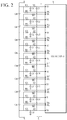
- FIG. 2 illustrates a first connection circuit between a cell monitoring IC and a battery cell assembly according to an exemplary embodiment
- the battery cell assembly 2 is illustrated as including eight cells Cell1 to Cell8 connected in series, but the present invention is not limited thereto.
- the first cell balancing resistor includes two cell balancing resistors RB1 and RB2.
- the temperature sensor 13 may include a temperature sensor disposed adjacent to the resistors RB1 and RB2.
- the first connection circuit 21 includes a plurality of resistors RC1 and RC2, a plurality of cell balancing resistors RB1 and RB2, and a plurality of capacitors C11 to C19 and C21 to C28.
- the cell monitoring IC 10 includes a plurality of terminals VC0 to VC8 for cell voltage sensing and a plurality of terminals CB1H to CB8H and CB1L to CB8L for cell balancing.
- two resistors RC1 and RC2 are connected in series between a positive electrode of a cell Celli and a terminal VCi.
- the two resistors RC1 and RC2 are connected in series between a negative electrode of the cell Celli and a terminal VC(i-1) (i is one of the natural numbers from 1 to 8).
- the terminal VC8 is connected to the positive electrode of the cell Cell8 through two resistors RC1 and RC2.
- the terminal VC7 is connected to a node to which the negative electrode of the cell Cell8 and the positive electrode of the cell Cell7 are connected, through two resistors RC1 and RC2.
- the terminal VC6 is connected to a node to which the negative electrode of the cell Cell7 and the positive electrode of the cell Cell6 are connected, through two resistors RC1 and RC2.
- the terminal VC5 is connected to a node to which the negative electrode of the cell Cell6 and the positive electrode of the cell Cell5 are connected, through two resistors RC1 and RC2.
- the terminal VC4 is connected to a node to which the negative electrode of the cell Cell5 and the positive electrode of the cell Cell4 are connected, through two resistors RC1 and RC2.
- the terminal VC3 is connected to a node to which the negative electrode of the cell Cell4 and the positive electrode of the cell Cell3 are connected, through two resistors RC1 and RC2.
- the terminal VC2 is connected to a node to which the negative electrode of the cell Cell3 and the positive electrode of the cell Cell2 are connected, through two resistors RC1 and RC2.
- the terminal VC1 is connected to a node to which the negative electrode of the cell Cell2 and the positive electrode of the cell Cell1 are connected, through two resistors RC1 and RC2.
- the terminal VC0 is connected to the negative electrode of the cell Cell1 through two resistors RC1 and RC2.
- the cell balancing resistor RB1 is connected between the positive electrode of the cell Celli and a terminal CBiH, and the cell balancing resistor RB2 is connected in series between the negative terminal of the cell Celli and a terminal CBiL (i is one of the natural numbers from 1 to 8).
- the terminal CB8H is connected to the positive electrode of the cell Cell8 through the cell balancing resistor RB1, and the terminal CB8L is connected to the negative electrode of the cell Cell8 through the cell balancing resistor RB2.
- the terminal CB7H is connected to the positive electrode of the cell Cell7 through the cell balancing resistor RB1, and the terminal CB7L is connected to the negative electrode of the cell Cell7 through the cell balancing resistor RB2.
- the terminal CB6H is connected to the positive electrode of the cell Cell6 through the cell balancing resistor RB1, and the terminal CB6L is connected to the negative electrode of the cell Cell6 through the cell balancing resistor RB2.
- the terminal CB5H is connected to the positive electrode of the cell Cell5 through the cell balancing resistor RB1, and the terminal CB5L is connected to the negative electrode of the cell Cell5 through the cell balancing resistor RB2.
- the terminal CB4H is connected to the positive electrode of the cell Cell4 through the cell balancing resistor RB1, and the terminal CB4L is connected to the negative electrode of the cell Cell4 through the cell balancing resistor RB2.
- the terminal CB3H is connected to the positive electrode of the cell Cell3 through the cell balancing resistor RB1, and the terminal CB3L is connected to the negative electrode of the cell Cell3 through the cell balancing resistor RB2.
- the terminal CB2H is connected to the positive electrode of the cell Cell2 through the cell balancing resistor RB1, and the terminal CB2L is connected to the negative electrode of the cell Cell8 through the cell balancing resistor RB2.
- the terminal CB1H is connected to the positive electrode of the cell Cell1 through the cell balancing resistor RB1, and the terminal CB1L is connected to the negative electrode of the cell Cell1 through the cell balancing resistor RB2.
- Each of the capacitors C11 to C19 is formed between a connection node between the two corresponding resistors RC1 and RC2 and the ground, and the capacitors C21 to C28 is formed between two corresponding terminals among the terminals VC0 to VC8.
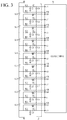
- FIG. 3 illustrates a second connection circuit between a cell balancing IC and a battery cell assembly according to an exemplary embodiment.
- the battery cell assembly 2 is illustrated as including cells Cell1 to Cell8 connected in series, but the present invention is not limited thereto.
- the second cell balancing resistor includes two cell balancing resistors RB3 and RB4.
- the temperature sensor 13 may include a temperature sensor disposed adjacent to the resistors RB3 and RB4.
- the second connection circuit 22 includes a plurality of resistors RC3 and RC4, a plurality of cell balancing resistors RB3 and RB4, and a plurality of capacitors C31 to C39 and C41 to C48.
- the cell balancing IC 20 includes a plurality of terminals vc0 to vc8 for cell voltage sensing and a plurality of terminals cB1h to cB8h and cB1l to cB8l for cell balancing.
- two resistors RC3 and RC4 are connected in series between a positive electrode of a cell Celli and a terminal vci.
- the two resistors RC3 and RC4 are connected in series between a negative electrode of the cell Celli and a terminal vc(i-1) (i is one of the natural numbers from 1 to 8).
- the terminal vc8 is connected to the positive electrode of the cell Cell8 through two resistors RC3 and RC4.
- the terminal vc7 is connected to a node to which the negative electrode of the cell Cell8 and the positive electrode of the cell Cell7 are connected, through two resistors RC3 and RC4.
- the terminal vc6 is connected to a node to which the negative electrode of the cell Cell7 and the positive electrode of the cell Cell6 are connected, through two resistors RC3 and RC4.
- the terminal vc5 is connected to a node to which the negative electrode of the cell Cell6 and the positive electrode of the cell Cell5 are connected, through two resistors RC3 and RC4.
- the terminal vc4 is connected to a node to which the negative electrode of the cell Cell5 and the positive electrode of the cell Cell4 are connected, through two resistors RC3 and RC4.
- the terminal vc3 is connected to a node to which the negative electrode of the cell Cell4 and the positive electrode of the cell Cell3 are connected, through two resistors RC3 and RC4.
- the terminal vc2 is connected to a node to which the negative electrode of the cell Cell3 and the positive electrode of the cell Cell2 are connected, through two resistors RC3 and RC4.
- the terminal vc1 is connected to a node to which the negative electrode of the cell Cell2 and the positive electrode of the cell Cell1 are connected, through two resistors RC3 and RC4.
- the terminal vc0 is connected to the negative electrode of the cell Cell1 through two resistors RC3 and RC4.
- the cell balancing resistor RB3 is connected between the positive electrode of the cell Celli and a terminal cbih, and the cell balancing resistor RB4 is connected in series between the negative electrode of the cell Celli and a terminal cbil. (i is one of the natural numbers from 1 to 8)
- the terminal cb8h is connected to the positive electrode of the cell Cell8 through the cell balancing resistor RB3, and the terminal cb8l is connected to the negative electrode of the cell Cell8 through the cell balancing resistor RB4.
- the terminal cb7h is connected to the positive electrode of the cell Cell7 through the cell balancing resistor RB3, and the terminal cb7l is connected to the negative electrode of the cell Cell7 through the cell balancing resistor RB4.
- the terminal cb6h is connected to the positive electrode of the cell Cell6 through the cell balancing resistor RB3, and the terminal cb6l is connected to the negative electrode of the cell Cell6 through the cell balancing resistor RB4.
- the terminal cb5h is connected to the positive electrode of the cell Cell5 through the cell balancing resistor RB3, and the terminal cb5l is connected to the negative electrode of the cell Cell5 through the cell balancing resistor RB4.
- the terminal cb4h is connected to the positive electrode of the cell Cell4 through the cell balancing resistor RB3, and the terminal cb4l is connected to the negative electrode of the cell Cell4 through the cell balancing resistor RB4.
- the terminal cb3h is connected to the positive electrode of the cell Cell3 through the cell balancing resistor RB3, and the terminal cb3l is connected to the negative electrode of the cell Cell3 through the cell balancing resistor RB4.
- the terminal cb2h is connected to the positive electrode of the cell Cell2 through the cell balancing resistor RB3, and the terminal cb2l is connected to the negative electrode of the cell Cell2 through the cell balancing resistor RB4.
- the terminal cb1h is connected to the positive electrode of the cell Cell1 through the cell balancing resistor RB3, and the terminal cb1l is connected to the negative electrode of the cell Cell1 through the cell balancing resistor RB4.
- Each of the capacitors C31 to C39 is formed between a connection node between the two corresponding resistors RC3 and RC4 and the ground, and the capacitors C41 to C48 are formed between two corresponding terminals among the terminals vc0 to vc8.
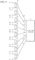
- FIG. 4 illustrates a partial configuration of a cell balancing IC according to an exemplary embodiment.
- the cell balancing IC 20 may include a plurality of cell balancing switches 101 to 108 and a cell balancing controller 100. Each of the cell balancing switches 101 to 108 may be connected between two corresponding terminals, and may perform a switching operation depending on a corresponding gate signal.
- the cell balancing controller 100 turns on the cell balancing switch connected to the cell balancing cell depending on the cell balancing control signal received from the main control circuit 30. An on period of the cell balancing switch may also depend on the cell balancing control signal.
- Each 10i of the cell balancing switches 101 to 108 may have a first end connected to the terminal cbih and a second end connected to the terminal cbil, and may perform the switching operation depending on a corresponding gate signal VGi.
- the cell balancing switch 10i When the cell balancing switch 10i is turned on, the cell Celli and the cell balancing resistors RB3 and RB4 form a discharge path to discharge the cell Celli (i is one of the natural numbers from 1 to 8).
- the cell balancing switches 101 to 108 and the cell balancing controller 100 illustrated in FIG. 4 may also be applied to the cell monitoring IC 10.
- the cell balancing switch 101 to 108 and the cell balancing controller 100 may be applied to the terminals CB1H to CB8H and CB1L to CB8L instead of the terminals cb1h h to cb8h and cb1l to cb8l illustrated in FIG. 4 .
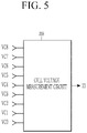
- FIG. 5 illustrates a partial configuration of a cell monitoring IC according to an exemplary embodiment.
- the cell monitoring IC 10 may include a cell voltage measurement circuit 200.
- the cell voltage measurement circuit 200 may measure a voltage between two adjacent terminals among the terminals VC8 to VC0 to transmit information indicating the measured cell voltage to the main control circuit 30 through the interface 23.
- the voltage between the terminal VCi and the terminal VC(i-1) is the cell voltage of the cell Celli (i is one of the natural numbers from 1 to 8).
- the cell voltage measurement circuit 200 illustrated in FIG. 5 may also be applied to the cell balancing IC 20.
- the cell voltage measurement circuit 200 may be applied to the terminals cb1h-cb8h and cb1l-cb8l instead of the terminals CB1H to CB8H and CB1L to CB8L illustrated in FIG. 5 .
- a connection relationship between a cell, a cell balancing resistor, and a cell balancing switch will be described in detail with reference to FIG. 6 and FIG. 7 .
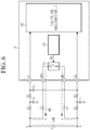
- FIG. 6 illustrates a partial configuration showing a connection relationship between a cell monitoring IC and a battery cell assembly according to an exemplary embodiment.
- FIG. 6 a plurality of resistors RC1 and RC2 connected to the cell Cell5, cell balancing resistors RB1 and RB2, a cell balancing switch 305, a cell balancing controller 300, and a cell voltage measurement circuit 200 are illustrated.
- the resistors RC1 and RC2 are connected in series between the positive electrode of the cell Cell5 and the terminal VC5, and the positive voltage of the cell Cell5 (or the negative voltage of Cell6) is transferred to the cell voltage measurement circuit 200 through the terminal VC5.
- the resistor RB1 is connected between the positive electrode of the cell Cell5 and the terminal CB5H
- a first end of the cell balancing switch 305 is connected to the terminal CB5H
- the resistor RB2 is connected between a negative electrode of the cell Cell5 and the terminal CB5L
- a second end of the cell balancing switch 305 is connected to the terminal CB5L.
- the cell balancing switch 305 performs a switching operation depending on a gate signal VG5 supplied from the cell balancing controller 300.
- the resistors RC1 and RC2 are connected in series between the negative electrode of the cell Cell5 and the terminal VC4, and the negative voltage of the cell Cell5 (or the positive voltage of Cell4) is transferred to the cell voltage measurement circuit 200 through the terminal VC4.
- the cell discharge switch 305 When the cell discharge switch 305 is turned on, the cell Cell5 is discharged along a discharge path BP1 that is formed of the cell Cell5, the cell balancing resistor RB1, the cell discharge switch 305, and the cell balancing resistor RB2.
- FIG. 7 illustrates a partial configuration showing a connection relationship between a cell balancing IC and a battery cell assembly according to an exemplary embodiment.
- FIG. 7 a plurality of resistors RC3 and RC4 connected to the cell Cell5, cell balancing resistors RB3 and RB4, a cell balancing switch 105, a cell balancing controller 100, and a cell voltage measurement circuit 400 are illustrated.
- the resistors RC3 and RC4 are connected in series between the positive electrode of the cell Cell5 and the terminal vc5, and the positive voltage of the cell Cell5 (or the negative voltage of Cell6) is transferred to the cell voltage measurement circuit 400 through the terminal vc5.
- the resistor RB3 is connected between the positive electrode of the cell Cell5 and the terminal cb5h
- a first end of the cell balancing switch 105 is connected to the terminal cb5h
- the resistor RB4 is connected between a negative electrode of the cell Cell5 and the terminal cb5l
- a second end of the cell balancing switch 105 is connected to the terminal cb5l.
- the cell balancing switch 105 performs a switching operation depending on a gate signal VG5 supplied from the cell balancing controller 100.
- the resistors RC3 and RC4 are connected in series between the negative electrode of the cell Cell5 and the terminal vc4, and the negative voltage of the cell Cell5 (or the positive voltage of Cell4) is transferred to the cell voltage measurement circuit 400 through the terminal vc4.
- the cell discharge switch 105 When the cell discharge switch 105 is turned on, the cell Cell5 is discharged along a discharge path BP2 that is formed of the cell Cell5, the cell balancing resistor RB3, the cell discharge switch 105, and the cell balancing resistor RB4.
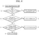
- FIG. 8 illustrates a flowchart showing a cell balancing control method depending on a voltage difference between cells of a main control circuit according to an exemplary embodiment.
- the main control circuit 30 calculates a voltage difference between the cells for each of the cells.
- the voltage difference between the cells may indicate a difference between a cell voltage of at least one of two cells adjacent to each of the cells and a cell voltage of the corresponding cell (S1).
- the main control circuit 30 compares a voltage difference between the cells and the first reference voltage (e.g., 1 V) (S2), selects a cell having a voltage difference between the cells that is equal to or higher than the first reference voltage as a cell balancing target cell as a result of the comparison, and controls both the cell monitoring IC 10 and the cell balancing IC 20 to perform a cell balancing operation (S3).
- the first reference voltage e.g. 1 V
- a first cell balancing current e.g., 100 mA
- a second cell balancing current e.g., 60 mA
- the main control circuit 30 compares the voltage difference between the cells and the second reference voltage (e.g., 0.5 V) (S4), selects a cell having a voltage difference between the cells that is lower than the first reference voltage and is higher than or equal to the second reference voltage as the cell balancing target cell as a result of the comparison, and controls the cell monitoring IC 20 to perform the cell balancing operation (S5). That is, in the cell monitoring IC 20, the first cell balancing current may flow through the first cell balancing resistors RB1 and RB2 connected to the corresponding cell.
- the second reference voltage e.g., 0.5 V
- the main control circuit 30 compares the voltage difference between the cells and the cell balancing threshold voltage (S6), selects a cell having a voltage difference between the cells that is higher than or equal to the cell balancing threshold voltage as the cell balancing target cell as a result of the comparison, and controls the cell balancing IC 20 to perform the cell balancing operation (S7). That is, in the cell balancing IC 20, the second cell balancing current may flow through the second cell balancing resistors RB3 and RB4 connected to the corresponding cell.
- step S6 when the voltage difference between the cells is smaller than the cell balancing threshold voltage, the cell balancing is not performed (S8).
- the main control circuit 30 may differently control the cell balancing method depending on a temperature of each of the first cell balancing resistors and the second cell balancing resistors corresponding to each of the cells.
- FIG. 9 illustrates a flowchart showing a cell balancing control method depending on a temperature of cell balancing resistors of a main control circuit according to an exemplary embodiment.
- the main control circuit 30 calculates the temperature of each of the first cell balancing resistor and the second cell balancing resistor depending on a measurement value received from the temperature sensor 13 (S9).
- the main control circuit 30 may receive a measurement value from each of the temperature sensors to calculate the temperature of each of the first cell balancing resistors and the second cell balancing resistors.
- the temperature sensor 13 may include a plurality of temperature sensors disposed adjacent to each of the first cell balancing resistors and the second cell balancing resistors connected to a cell at a specific location among the cells or at least two cells spaced apart from each other, or the like.
- the main control circuit 30 compares the temperature of each of the first cell balancing resistors and the second cell balancing resistors with a reference temperature (e.g., 100 degrees) (S10).
- a reference temperature e.g. 100 degrees
- the temperature of the first cell balancing resistors is referred to as a first resistance temperature
- the temperature of the second cell balancing resistors is referred to as a second resistance temperature.
- the cell balancing target cell is discharged by using the first cell balancing current through the first cell balancing resistors (S11).
- the cell balancing target cell is discharged by using the second cell balancing current through the second cell balancing resistors (S12).
- the method of selecting the cell balancing target cell may depend on the flowchart shown in FIG. 8 .
- the main control circuit 30 controls the cell monitoring IC 10 and the cell balancing IC 20 to discharge the corresponding cell through the first cell balancing resistors RB1 and RB2 and the second cell balancing resistors RB3 and RB4 by using the first cell balancing current and the second cell balancing current.
- the main control circuit 30 may control the cell monitoring IC 10 and the cell balancing IC 20 to use the second cell balancing resistors RB3 and RB4 when the temperature of the first cell balancing resistors RB1 and RB2 is higher than or equal to the reference temperature and to use the first cell balancing resistors RB1 and RB2 when the temperature of the second cell balancing resistors RB3 and RB4 is higher than or equal to the reference temperature.
- the first cell balancing resistors RB1 and RB2 When the temperature of the first cell balancing resistors RB1 and RB2 is reduced from a temperature that is equal to or higher than the reference temperature to be lower than the reference temperature, the first cell balancing resistors RB1 and RB2 may also be used for the cell balancing. Similarly, when the temperature of the second cell balancing resistors RB3 and RB4 is reduced from a temperature that is equal to or higher than the reference temperature to be lower than the reference temperature, the second cell balancing resistors RB3 and RB4 may also be used for the cell balancing.
- the main control circuit 30 controls the cell monitoring IC 10 and the cell balancing IC 20 to discharge the corresponding cell through the first cell balancing resistors RB1 and RB2 by using the first cell balancing current.
- the main control circuit 30 may control the cell monitoring IC 10 and the cell balancing IC 20 to use the second cell balancing resistors RB3 and RB4 instead of the first cell balancing resistors RB1 and RB2 when the temperature of the first cell balancing resistors RB1 and RB2 is equal to or higher than the reference temperature.
- the first cell balancing resistors RB1 and RB2 may also be used for the cell balancing, instead of the second cell balancing resistors RB3 and RB4.
- the main control circuit 30 controls the cell monitoring IC 10 and the cell balancing IC 20 to discharge the corresponding cell through the second cell balancing resistors RB3 and RB4 by using the second cell balancing current.
- the main control circuit 30 may control the cell monitoring IC 10 and the cell balancing IC 20 to use the first cell balancing resistors RB1 and RB2 instead of the second cell balancing resistors RB3 and RB4 when the temperature of the second cell balancing resistors RB3 and RB4 is equal to or higher than the reference temperature.
- the second cell balancing resistors RB3 and RB4 may also be used for the cell balancing, instead of the first cell balancing resistors RB1 and RB2.
- the battery management system may perform cell balancing by using at least two cell balancing currents by adding a cell balancing IC, unlike using only an existing cell monitoring IC. Then, it is possible to reduce a time required for cell balancing by using a larger cell balancing current than that in the prior art, and provide an effect of performing more sophisticated cell balancing.
Landscapes
- Engineering & Computer Science (AREA)
- Manufacturing & Machinery (AREA)
- Chemical & Material Sciences (AREA)
- Chemical Kinetics & Catalysis (AREA)
- Electrochemistry (AREA)
- General Chemical & Material Sciences (AREA)
- Power Engineering (AREA)
- Microelectronics & Electronic Packaging (AREA)
- Charge And Discharge Circuits For Batteries Or The Like (AREA)
- Secondary Cells (AREA)
Abstract
Description
- This application claims priority to and the benefit of
Korean Patent Application No. 10-2019-0056452 - The present disclosure relates to a battery management system, and more particularly, to a battery management system for cell balancing control.
- A battery management system (hereinafter referred to as "BMS") that monitors a state of a battery and controls charging and discharging of the battery controls a cell balancing operation in order to similarly maintain voltages of a plurality of cells constituting the battery. A voltage difference between the cells causes cell deterioration, which affects a lifespan thereof, and a deterioration of a cell having a cell voltage that is significantly different from that of another cell among the cells is increased, and such a cell may cause overcharging.
- Among cell balancing methods, a passive cell balancing method is a method by which a resistor is connected to a cell having a great cell voltage difference with other cells to allow a current (hereinafter referred to as "a cell balancing current") to flow from the corresponding cell to the resistor. In this case, as the cell balancing current increases, a cell balancing operation time may decrease.
- When cell balancing is performed using a cell monitoring IC under the control of a conventional BMS, as the cell balancing current is limited according to a function of the cell monitoring IC, there is a limit in reducing the time required for cell balancing.
- The present invention has been made in an effort to provide a battery management system and a battery device including the same, capable of adjusting a cell balancing current.
- An exemplary embodiment of the present invention provides a battery management system of a battery cell assembly including a plurality of cells, including: a first cell balancing resistor and a first cell balancing switch connected between a positive electrode and a negative electrode of a corresponding first cell among the cells; and a second cell balancing resistor and a second cell balancing switch connected between the positive electrode and the negative electrode of the first cell. A first cell balancing current flowing during an on period of the first cell balancing switch may be greater than a second cell balancing current flowing during an on period of the second cell balancing switch.
- The first cell balancing resistor may include: a first resistor connected between a positive electrode of the first cell and a first end of the first cell balancing switch; and a second resistor connected between a negative electrode of the first cell and a second end of the first cell balancing switch.
- The second cell balancing resistor may include: a third resistor connected between a positive electrode of the first cell and a first end of the second cell balancing switch; and a fourth resistor connected between a negative electrode of the first cell and a second end of the second cell balancing switch.
- The battery management system may turn on both the first cell balancing switch and the second cell balancing switch when a voltage difference between the cells, which is a voltage difference between the first cell and at least one cell adjacent to the first cell, is higher than or equal to a first reference voltage.
- The battery management system may turn on the first cell balancing switch when the voltage difference between the cells is higher than or equal to a second reference voltage and lower than the first reference voltage.
- The battery management system may turn on the second cell balancing switch when the voltage difference between the cells is higher than or equal to the cell balancing threshold voltage and lower than the second reference voltage.
- The battery management system , when the temperature of the first cell balancing resistor is higher than or equal to the reference temperature and the temperature of the second cell balancing resistor is lower than the reference temperature, may control cell balancing of the first cell by using the second cell balancing resistor.
- The battery management system, when the temperature of the second cell balancing resistor is higher than or equal to the reference temperature and the temperature of the first cell balancing resistor is lower than the reference temperature, may control cell balancing of the first cell by using the first cell balancing resistor.
- Another exemplary embodiment of the present invention provides a battery management system of a battery cell assembly including a plurality of cells, including: a cell monitoring IC configured to include a plurality of first cell balancing switches corresponding to the cells, the first cell balancing switches being connected to the cells through the first cell balancing resistors; a cell balancing IC configured to include a plurality of second cell balancing switches corresponding to the cells, the second cell balancing switches being connected to the cells through the second cell balancing resistors; and a main control circuit configured to calculate a voltage difference between the cells for each cell of the cells based on received cell voltages of the cells, to determine a cell balancing target cell depending on results of comparing the voltage difference between the cells with the first reference voltage, the second reference voltage, and the cell balancing threshold voltage, and to control the cell balancing operation by using at least one of the cell monitoring IC and the cell balancing IC depending on the comparison results. A voltage difference between the cells may be a difference between a cell voltage of each of the cells and at least one cell adjacent to each of the cells.
- A first cell balancing current flowing through a turned-on first cell balancing switch among the first cell balancing switches may be larger than a second cell balancing current flowing through a turned-on second cell balancing switch among the second cell balancing switches.
- The main control circuit may control the cell monitoring IC and the cell balancing IC to turn on both the first cell balancing switch and the second cell balancing switch connected to a cell having a voltage difference between the cells that is higher than or equal to a first reference voltage among a plurality of voltage differences between the cells.
- The main control circuit may control the cell monitoring IC and the cell balancing IC to turn on the first cell balancing switch connected to a cell having a voltage difference between cells that is higher than or equal to a second reference voltage and lower than the first reference voltage among the voltage differences between the cells.
- The main control circuit may control the cell monitoring IC and the cell balancing IC to turn on the second cell balancing switch connected to a cell having a voltage difference between cells that is higher than or equal to a cell balancing threshold voltage and lower than the second reference voltage among the voltage differences between the cells.
- The main control circuit may control the cell monitoring IC and the cell balancing IC to perform cell balancing of a first cell by using the second cell balancing resistor connected to the first cell, for the first cell that is connected to the first cell balancing resistor having a temperature that is equal to or higher than a reference temperature among the first cell balancing resistors.
- The main control circuit may control the cell monitoring IC and the cell balancing IC to perform cell balancing of a first cell by using the first cell balancing resistor connected to the first cell, for the first cell that is connected to the second cell balancing resistor having a temperature that is equal to or higher than a reference temperature among the second cell balancing resistors.
- It is possible to provide a battery management system and a battery device that can improve accuracy of cell balancing by adjusting the cell balancing current and can shorten a cell balancing operation time.
-
-
FIG. 1 illustrates a battery device according to an exemplary embodiment. -
FIG. 2 illustrates a first connection circuit between a cell monitoring IC and a battery cell assembly according to an exemplary embodiment -
FIG. 3 illustrates a second connection circuit between a cell balancing IC and a battery cell assembly according to an exemplary embodiment. -
FIG. 4 illustrates a partial configuration of a cell balancing IC according to an exemplary embodiment. -
FIG. 5 illustrates a partial configuration of a cell monitoring IC according to an exemplary embodiment. -
FIG. 6 illustrates a partial configuration showing a connection relationship between a cell monitoring IC and a battery cell assembly according to an exemplary embodiment. -
FIG. 7 illustrates a partial configuration showing a connection relationship between a cell balancing IC and a battery cell assembly according to an exemplary embodiment. -
FIG. 8 illustrates a flowchart showing a cell balancing control method depending on a voltage difference between cells of a main control circuit according to an exemplary embodiment. -
FIG. 9 illustrates a flowchart showing a cell balancing control method depending on a temperature of cell balancing resistors of a main control circuit according to an exemplary embodiment. - According to an exemplary embodiment of the present invention, a battery management system includes not only a cell monitoring IC but also a cell balancing IC, and the cell balancing IC provides a cell balancing current (hereinafter referred to as "a second cell balancing current") that is different from a cell balancing current (hereinafter referred to as "a first cell balancing current") of the cell monitoring IC. When a voltage difference between one cell and another cell that is adjacent to the cell among a plurality of cells (hereinafter referred to as a "a voltage difference between cells") is equal to or greater than a predetermined cell balancing threshold voltage, a cell balancing operation may be performed on the corresponding cell (hereinafter a cell balancing target cell) depending on a result of comparison with at least two reference voltages, i.e., a first reference voltage and a second reference voltage, by using at least one of a first cell balancing current and a second cell balancing current. The first cell balancing current may be larger than the second cell balancing current.
- In this case, the cell balancing operation may be performed by using only one of the first cell balancing current and the second cell balancing current depending on temperatures of a resistor for cell balancing of the cell monitoring IC (hereinafter referred to as a first cell balancing resistor) and a resistor for cell balancing of the cell balancing IC (hereinafter referred to as a second cell balancing resistor) as well as the cell voltage difference.
- Hereinafter, exemplary embodiments disclosed in the present specification will be described in detail with reference to the accompanying drawings. In the present specification, the same or similar components will be denoted by the same or similar reference numerals, and a repeated description thereof will be omitted. Terms "module" and/or "unit" for components used in the following description are used only in order to easily describe the specification. Therefore, these terms do not have meanings or roles that distinguish them from each other in and of themselves. In describing exemplary embodiments of the present specification, when it is determined that a detailed description of the well-known art associated with the present invention may obscure the gist of the present invention, it will be omitted. The accompanying drawings are provided only in order to allow exemplary embodiments disclosed in the present specification to be easily understood and are not to be interpreted as limiting the spirit disclosed in the present specification, and it is to be understood that the present invention includes all modifications, equivalents, and substitutions without departing from the scope and spirit of the present invention.
- Terms including ordinal numbers such as first, second, and the like will be used only to describe various components, and are not to be interpreted as limiting these components. The terms are only used to differentiate one component from other components.
- It is to be understood that when one component is referred to as being "connected" or "coupled" to another component, it may be connected or coupled directly to the other component or be connected or coupled to the other component with a further component intervening therebetween. On the other hand, it is to be understood that when one component is referred to as being "connected or coupled directly" to another component, it may be connected to or coupled to the other component without another component intervening therebetween.
- It will be further understood that terms "comprise" or "have" used in the present specification specifies the presence of stated features, numerals, steps, operations, components, parts, or a combination thereof, but does not preclude the presence or addition of one or more other features, numerals, steps, operations, components, parts, or a combination thereof.
-
FIG. 1 illustrates a battery device according to an exemplary embodiment. - As illustrated in
FIG. 1 , thebattery device 1 includes abattery cell assembly 2, a BMS 3, arelay 11, ashunt resistor 12, and atemperature sensor 13. - In the
battery cell assembly 2, a plurality of battery cells are connected in series or parallel to supply necessary power. InFIG. 1 , thebattery cell assembly 2 includes a plurality of battery cells Cell1 to Celln that are connected in series and is connected between two output terminals OUT1 and OUT2 of thebattery device 1, therelay 11 is connected between a positive electrode of thebattery device 1 and the output terminal OUT1, and theshunt resistor 12 is connected between a negative electrode of thebattery device 1 and the output terminal OUT2. The constituent elements illustrated inFIG. 1 and a connection relationship between the constituent elements are examples, and the present invention is not limited thereto. - The
relay 11 controls electrical connection between thebattery device 1 and a load. When therelay 11 is turned on, thebattery device 1 and the load are electrically connected to perform charging or discharging, and when therelay 11 is turned off, thebattery device 1 and the load are electrically separated. - The
shunt resistor 12 is connected in series to a current path between thebattery cell assembly 2 and the load (not illustrated). The BMS 3 may measure a voltage across theshunt resistor 12 to calculate a current flowing through thebattery cell assembly 2, that is, a charge current and a discharge current. - The
temperature sensor 13 may be disposed at a predetermined position within thebattery device 1, e.g., in an area that is adjacent to thebattery cell assembly 2, or may be physically coupled to thebattery cell assembly 2. Thetemperature sensor 13 may detect a temperature of the position at which it is disposed, and transmit information indicating the detected temperature to the BMS 3. Although not illustrated inFIG. 1 , at least twotemperature sensors 13 may be provided to measure a temperature of each of the first cell balancing resistor and the second cell balancing resistor, or to provide temperature information for estimating the temperature of each of the first cell balancing resistor and the second cell balancing resistor. The first cell balancing resistor is connected between acell monitoring IC 10 and the cells Cell1 to Celln, and thus when performing cell balancing, the first cell balancing current flows through the first cell balancing resistor. The second cell balancing resistor is connected between acell balancing IC 20 and the cells Cell1 to Celln, and thus when performing cell balancing, the second cell balancing current flows through the second cell balancing resistor. - The BMS 3 includes a
first connection circuit 21, asecond connection circuit 22, thecell monitoring IC 10, thecell balancing IC 20, amain control circuit 30, and arelay driver 40. - The
cell monitoring IC 10 and thebattery cell assembly 2 may be electrically connected through thefirst connection circuit 21, and thecell balancing IC 20 and thebattery cell assembly 2 may be electrically connected through thesecond connection circuit 22. - The
cell monitoring IC 10 may be electrically connected to each of the cells through thefirst connection circuit 21 to measure a cell voltage, and may measure a current flowing through the battery (hereinafter referred to as "battery current") based on the voltage across theshunt resistor 12. Information related to the cell voltage and the battery current measured by thecell monitoring IC 10 is transmitted to themain control circuit 30 through aninterface 23. Thecell monitoring IC 10 may discharge a cell balancing cell among the cells Cell1 to Celln by using the first cell balancing resistor depending on a cell balancing control signal (hereinafter referred to as "a first cell balancing control signal") transmitted from themain control circuit 30 through theinterface 23. - The
cell balancing IC 20 may be electrically connected to each of the cells through thesecond connection circuit 22 to measure the cell voltage, and may measure the battery current based on the voltage across theshunt resistor 12. Information related to the cell voltage and the battery current measured by thecell balancing IC 20 is transmitted to themain control circuit 30 through aninterface 24. Thecell balancing IC 20 may discharge a cell balancing cell among the cells Cell1 to Celln by using the second cell balancing resistor depending on a cell balancing control signal (hereinafter referred to as "a second cell balancing control signal") transmitted from themain control circuit 30 through theinterface 24. - In addition, the
cell monitoring IC 10 and thecell balancing IC 20 may control a plurality of cell control operations required for a protection operation depending on protection operation control signals transmitted from themain control circuit 30 through the correspondinginterface - The
main control circuit 30 may receive a wake-up signal from, e.g., an electronic control unit (ECU) 5 of a vehicle from the outside so as to activate thecell balancing IC 20 and thecell monitoring IC 10 which are in a sleep state. In addition, the wake-up signal may be transmitted to themain control circuit 30 when an abnormal voltage that is equal to or higher than a certain level at a cell side is detected by at least one of thecell balancing IC 20 and thecell monitoring IC 10. - The
main control circuit 30 may control an operation of therelay 11 based on state information received through theinterface 23 and theinterface 24 from thecell monitoring IC 10 and thecell balancing IC 20, respectively, and may control cell balancing by controlling at least one of thecell monitoring IC 10 and thecell balancing IC 20. - Specifically, the
main control circuit 30 calculates a voltage difference between the cells for each cell of the cells based on received cell voltages of the cells Cell1 to Celln, determines a cell balancing target cell depending on results of comparing the voltage difference between the cells with the first reference voltage, the second reference voltage, and the cell balancing threshold voltage, and controls the cell balancing operation by using at least one of thecell monitoring IC 10 and thecell balancing IC 20 depending on the comparison results. - According to an exemplary embodiment, the voltage difference between cells may be a difference between a cell voltage of each cell and a cell voltage of at least one cell adjacent to each cell among the cells Cell1 to Celln. For example, at least one of the adjacent cells disposed above and below each cell may be the adjacent cell. In the cell balancing, a voltage difference between two adjacent cells may be specified based on a low voltage cell.
- When the voltage difference between the cells is equal to or higher than the first reference voltage, the
main control circuit 30 may control thecell monitoring IC 10 and thecell balancing IC 20 to turn on both of a first cell balancing switch and a second cell balancing switch connected to cells having a voltage difference between cells that is equal to or higher than the first reference voltage. Themain control circuit 30 may control thecell monitoring IC 10 and thecell balancing IC 20 to turn on the first cell balancing switch connected to cells having a voltage difference between cells that is equal to or higher than the second reference voltage and lower than the first reference voltage. Themain control circuit 30 may control thecell monitoring IC 10 and thecell balancing IC 20 to turn on the second cell balancing switch connected to cells having a voltage difference between cells that is equal to or higher than the cell balancing threshold voltage and lower than the second reference voltage. - In addition, the
main control circuit 30 may control thecell monitoring IC 10 and thecell balancing IC 20 to perform cell balancing of a first cell by using the second cell balancing resistor connected to the first cell, for the first cell that is connected to a first cell balancing resistor having a temperature that is equal to or higher than a reference temperature among a plurality of first cell balancing resistors. In addition, themain control circuit 30 may control thecell monitoring IC 10 and thecell balancing IC 20 to perform cell balancing of a first cell by using the first cell balancing resistor connected to the first cell, for the first cell that is connected to a second cell balancing resistor having a temperature that is equal to or higher than the reference temperature among a plurality of second cell balancing resistors. - With respect to the cell balancing, the
main control circuit 30 may transmit the first cell balancing control signal and the second cell balancing control signal to control thecell monitoring IC 10 andcell balancing IC 20. - In addition, when it is determined that an abnormal state such as a cell overvoltage, a cell undervoltage, a short circuit, or an overcurrent has occurred based on the state information, the
main control circuit 30 may generate a protection operation control signal for driving a protection operation corresponding to the abnormal state that has occurred and transmit it to thecell monitoring IC 10 and thecell balancing IC 20. Themain control circuit 30 may transmit information related to thebattery device 1 through CAN communication with theECU 5, and may receive an instruction related to an operation of thebattery device 1 from the ECU, so as to control therelay 11, thecell monitoring IC 10, and thecell balancing IC 20. - The configuration of the
battery device 1 according to the present exemplary embodiment has been described with reference toFIG. 1 , and each constituent element will be described later with reference toFIG. 2 to FIG. 7 . -
FIG. 2 illustrates a first connection circuit between a cell monitoring IC and a battery cell assembly according to an exemplary embodiment - In
FIG. 2 , thebattery cell assembly 2 is illustrated as including eight cells Cell1 to Cell8 connected in series, but the present invention is not limited thereto. InFIG. 2 , the first cell balancing resistor includes two cell balancing resistors RB1 and RB2. Thetemperature sensor 13 may include a temperature sensor disposed adjacent to the resistors RB1 and RB2. - The
first connection circuit 21 includes a plurality of resistors RC1 and RC2, a plurality of cell balancing resistors RB1 and RB2, and a plurality of capacitors C11 to C19 and C21 to C28. Thecell monitoring IC 10 includes a plurality of terminals VC0 to VC8 for cell voltage sensing and a plurality of terminals CB1H to CB8H and CB1L to CB8L for cell balancing. - In
FIG. 2 , two resistors RC1 and RC2 are connected in series between a positive electrode of a cell Celli and a terminal VCi. Alternatively, the two resistors RC1 and RC2 are connected in series between a negative electrode of the cell Celli and a terminal VC(i-1) (i is one of the natural numbers from 1 to 8). - Specifically, the terminal VC8 is connected to the positive electrode of the cell Cell8 through two resistors RC1 and RC2. The terminal VC7 is connected to a node to which the negative electrode of the cell Cell8 and the positive electrode of the cell Cell7 are connected, through two resistors RC1 and RC2. The terminal VC6 is connected to a node to which the negative electrode of the cell Cell7 and the positive electrode of the cell Cell6 are connected, through two resistors RC1 and RC2. The terminal VC5 is connected to a node to which the negative electrode of the cell Cell6 and the positive electrode of the cell Cell5 are connected, through two resistors RC1 and RC2. The terminal VC4 is connected to a node to which the negative electrode of the cell Cell5 and the positive electrode of the cell Cell4 are connected, through two resistors RC1 and RC2. The terminal VC3 is connected to a node to which the negative electrode of the cell Cell4 and the positive electrode of the cell Cell3 are connected, through two resistors RC1 and RC2. The terminal VC2 is connected to a node to which the negative electrode of the cell Cell3 and the positive electrode of the cell Cell2 are connected, through two resistors RC1 and RC2. The terminal VC1 is connected to a node to which the negative electrode of the cell Cell2 and the positive electrode of the cell Cell1 are connected, through two resistors RC1 and RC2. The terminal VC0 is connected to the negative electrode of the cell Cell1 through two resistors RC1 and RC2.
- In
FIG. 2 , the cell balancing resistor RB1 is connected between the positive electrode of the cell Celli and a terminal CBiH, and the cell balancing resistor RB2 is connected in series between the negative terminal of the cell Celli and a terminal CBiL (i is one of the natural numbers from 1 to 8). - Specifically, the terminal CB8H is connected to the positive electrode of the cell Cell8 through the cell balancing resistor RB1, and the terminal CB8L is connected to the negative electrode of the cell Cell8 through the cell balancing resistor RB2. The terminal CB7H is connected to the positive electrode of the cell Cell7 through the cell balancing resistor RB1, and the terminal CB7L is connected to the negative electrode of the cell Cell7 through the cell balancing resistor RB2. The terminal CB6H is connected to the positive electrode of the cell Cell6 through the cell balancing resistor RB1, and the terminal CB6L is connected to the negative electrode of the cell Cell6 through the cell balancing resistor RB2. The terminal CB5H is connected to the positive electrode of the cell Cell5 through the cell balancing resistor RB1, and the terminal CB5L is connected to the negative electrode of the cell Cell5 through the cell balancing resistor RB2. The terminal CB4H is connected to the positive electrode of the cell Cell4 through the cell balancing resistor RB1, and the terminal CB4L is connected to the negative electrode of the cell Cell4 through the cell balancing resistor RB2. The terminal CB3H is connected to the positive electrode of the cell Cell3 through the cell balancing resistor RB1, and the terminal CB3L is connected to the negative electrode of the cell Cell3 through the cell balancing resistor RB2. The terminal CB2H is connected to the positive electrode of the cell Cell2 through the cell balancing resistor RB1, and the terminal CB2L is connected to the negative electrode of the cell Cell8 through the cell balancing resistor RB2. The terminal CB1H is connected to the positive electrode of the cell Cell1 through the cell balancing resistor RB1, and the terminal CB1L is connected to the negative electrode of the cell Cell1 through the cell balancing resistor RB2.
- Each of the capacitors C11 to C19 is formed between a connection node between the two corresponding resistors RC1 and RC2 and the ground, and the capacitors C21 to C28 is formed between two corresponding terminals among the terminals VC0 to VC8.
-
FIG. 3 illustrates a second connection circuit between a cell balancing IC and a battery cell assembly according to an exemplary embodiment. - In
FIG. 3 , thebattery cell assembly 2 is illustrated as including cells Cell1 to Cell8 connected in series, but the present invention is not limited thereto. InFIG. 3 , the second cell balancing resistor includes two cell balancing resistors RB3 and RB4. Thetemperature sensor 13 may include a temperature sensor disposed adjacent to the resistors RB3 and RB4. - The
second connection circuit 22 includes a plurality of resistors RC3 and RC4, a plurality of cell balancing resistors RB3 and RB4, and a plurality of capacitors C31 to C39 and C41 to C48. Thecell balancing IC 20 includes a plurality of terminals vc0 to vc8 for cell voltage sensing and a plurality of terminals cB1h to cB8h and cB1l to cB8l for cell balancing. InFIG. 3 , two resistors RC3 and RC4 are connected in series between a positive electrode of a cell Celli and a terminal vci. Alternatively, the two resistors RC3 and RC4 are connected in series between a negative electrode of the cell Celli and a terminal vc(i-1) (i is one of the natural numbers from 1 to 8). - Specifically, the terminal vc8 is connected to the positive electrode of the cell Cell8 through two resistors RC3 and RC4. The terminal vc7 is connected to a node to which the negative electrode of the cell Cell8 and the positive electrode of the cell Cell7 are connected, through two resistors RC3 and RC4. The terminal vc6 is connected to a node to which the negative electrode of the cell Cell7 and the positive electrode of the cell Cell6 are connected, through two resistors RC3 and RC4. The terminal vc5 is connected to a node to which the negative electrode of the cell Cell6 and the positive electrode of the cell Cell5 are connected, through two resistors RC3 and RC4. The terminal vc4 is connected to a node to which the negative electrode of the cell Cell5 and the positive electrode of the cell Cell4 are connected, through two resistors RC3 and RC4. The terminal vc3 is connected to a node to which the negative electrode of the cell Cell4 and the positive electrode of the cell Cell3 are connected, through two resistors RC3 and RC4. The terminal vc2 is connected to a node to which the negative electrode of the cell Cell3 and the positive electrode of the cell Cell2 are connected, through two resistors RC3 and RC4. The terminal vc1 is connected to a node to which the negative electrode of the cell Cell2 and the positive electrode of the cell Cell1 are connected, through two resistors RC3 and RC4. The terminal vc0 is connected to the negative electrode of the cell Cell1 through two resistors RC3 and RC4.
- In
FIG. 3 , the cell balancing resistor RB3 is connected between the positive electrode of the cell Celli and a terminal cbih, and the cell balancing resistor RB4 is connected in series between the negative electrode of the cell Celli and a terminal cbil. (i is one of the natural numbers from 1 to 8) - Specifically, the terminal cb8h is connected to the positive electrode of the cell Cell8 through the cell balancing resistor RB3, and the terminal cb8l is connected to the negative electrode of the cell Cell8 through the cell balancing resistor RB4. The terminal cb7h is connected to the positive electrode of the cell Cell7 through the cell balancing resistor RB3, and the terminal cb7l is connected to the negative electrode of the cell Cell7 through the cell balancing resistor RB4. The terminal cb6h is connected to the positive electrode of the cell Cell6 through the cell balancing resistor RB3, and the terminal cb6l is connected to the negative electrode of the cell Cell6 through the cell balancing resistor RB4. The terminal cb5h is connected to the positive electrode of the cell Cell5 through the cell balancing resistor RB3, and the terminal cb5l is connected to the negative electrode of the cell Cell5 through the cell balancing resistor RB4. The terminal cb4h is connected to the positive electrode of the cell Cell4 through the cell balancing resistor RB3, and the terminal cb4l is connected to the negative electrode of the cell Cell4 through the cell balancing resistor RB4. The terminal cb3h is connected to the positive electrode of the cell Cell3 through the cell balancing resistor RB3, and the terminal cb3l is connected to the negative electrode of the cell Cell3 through the cell balancing resistor RB4. The terminal cb2h is connected to the positive electrode of the cell Cell2 through the cell balancing resistor RB3, and the terminal cb2l is connected to the negative electrode of the cell Cell2 through the cell balancing resistor RB4. The terminal cb1h is connected to the positive electrode of the cell Cell1 through the cell balancing resistor RB3, and the terminal cb1l is connected to the negative electrode of the cell Cell1 through the cell balancing resistor RB4.
- Each of the capacitors C31 to C39 is formed between a connection node between the two corresponding resistors RC3 and RC4 and the ground, and the capacitors C41 to C48 are formed between two corresponding terminals among the terminals vc0 to vc8.
-
FIG. 4 illustrates a partial configuration of a cell balancing IC according to an exemplary embodiment. - The
cell balancing IC 20 may include a plurality of cell balancing switches 101 to 108 and acell balancing controller 100. Each of the cell balancing switches 101 to 108 may be connected between two corresponding terminals, and may perform a switching operation depending on a corresponding gate signal. - The
cell balancing controller 100 turns on the cell balancing switch connected to the cell balancing cell depending on the cell balancing control signal received from themain control circuit 30. An on period of the cell balancing switch may also depend on the cell balancing control signal. - Each 10i of the cell balancing switches 101 to 108 may have a first end connected to the terminal cbih and a second end connected to the terminal cbil, and may perform the switching operation depending on a corresponding gate signal VGi. When the cell balancing switch 10i is turned on, the cell Celli and the cell balancing resistors RB3 and RB4 form a discharge path to discharge the cell Celli (i is one of the natural numbers from 1 to 8).
- The cell balancing switches 101 to 108 and the
cell balancing controller 100 illustrated inFIG. 4 may also be applied to thecell monitoring IC 10. In this case, thecell balancing switch 101 to 108 and thecell balancing controller 100 may be applied to the terminals CB1H to CB8H and CB1L to CB8L instead of the terminals cb1h h to cb8h and cb1l to cb8l illustrated inFIG. 4 . -
FIG. 5 illustrates a partial configuration of a cell monitoring IC according to an exemplary embodiment. - The
cell monitoring IC 10 may include a cellvoltage measurement circuit 200. The cellvoltage measurement circuit 200 may measure a voltage between two adjacent terminals among the terminals VC8 to VC0 to transmit information indicating the measured cell voltage to themain control circuit 30 through theinterface 23. The voltage between the terminal VCi and the terminal VC(i-1) is the cell voltage of the cell Celli (i is one of the natural numbers from 1 to 8). - The cell
voltage measurement circuit 200 illustrated inFIG. 5 may also be applied to thecell balancing IC 20. In this case, the cellvoltage measurement circuit 200 may be applied to the terminals cb1h-cb8h and cb1l-cb8l instead of the terminals CB1H to CB8H and CB1L to CB8L illustrated inFIG. 5 . - A connection relationship between a cell, a cell balancing resistor, and a cell balancing switch will be described in detail with reference to
FIG. 6 andFIG. 7 . -
FIG. 6 illustrates a partial configuration showing a connection relationship between a cell monitoring IC and a battery cell assembly according to an exemplary embodiment. - In
FIG. 6 , a plurality of resistors RC1 and RC2 connected to the cell Cell5, cell balancing resistors RB1 and RB2, acell balancing switch 305, acell balancing controller 300, and a cellvoltage measurement circuit 200 are illustrated. - The resistors RC1 and RC2 are connected in series between the positive electrode of the cell Cell5 and the terminal VC5, and the positive voltage of the cell Cell5 (or the negative voltage of Cell6) is transferred to the cell
voltage measurement circuit 200 through the terminal VC5. The resistor RB1 is connected between the positive electrode of the cell Cell5 and the terminal CB5H, a first end of thecell balancing switch 305 is connected to the terminal CB5H, the resistor RB2 is connected between a negative electrode of the cell Cell5 and the terminal CB5L, and a second end of thecell balancing switch 305 is connected to the terminal CB5L. Thecell balancing switch 305 performs a switching operation depending on a gate signal VG5 supplied from thecell balancing controller 300. - The resistors RC1 and RC2 are connected in series between the negative electrode of the cell Cell5 and the terminal VC4, and the negative voltage of the cell Cell5 (or the positive voltage of Cell4) is transferred to the cell
voltage measurement circuit 200 through the terminal VC4. - When the
cell discharge switch 305 is turned on, the cell Cell5 is discharged along a discharge path BP1 that is formed of the cell Cell5, the cell balancing resistor RB1, thecell discharge switch 305, and the cell balancing resistor RB2. -
FIG. 7 illustrates a partial configuration showing a connection relationship between a cell balancing IC and a battery cell assembly according to an exemplary embodiment. - In
FIG. 7 , a plurality of resistors RC3 and RC4 connected to the cell Cell5, cell balancing resistors RB3 and RB4, acell balancing switch 105, acell balancing controller 100, and a cellvoltage measurement circuit 400 are illustrated. - The resistors RC3 and RC4 are connected in series between the positive electrode of the cell Cell5 and the terminal vc5, and the positive voltage of the cell Cell5 (or the negative voltage of Cell6) is transferred to the cell
voltage measurement circuit 400 through the terminal vc5. The resistor RB3 is connected between the positive electrode of the cell Cell5 and the terminal cb5h, a first end of thecell balancing switch 105 is connected to the terminal cb5h, the resistor RB4 is connected between a negative electrode of the cell Cell5 and the terminal cb5l, and a second end of thecell balancing switch 105 is connected to the terminal cb5l. Thecell balancing switch 105 performs a switching operation depending on a gate signal VG5 supplied from thecell balancing controller 100. - The resistors RC3 and RC4 are connected in series between the negative electrode of the cell Cell5 and the terminal vc4, and the negative voltage of the cell Cell5 (or the positive voltage of Cell4) is transferred to the cell
voltage measurement circuit 400 through the terminal vc4. - When the
cell discharge switch 105 is turned on, the cell Cell5 is discharged along a discharge path BP2 that is formed of the cell Cell5, the cell balancing resistor RB3, thecell discharge switch 105, and the cell balancing resistor RB4. -
FIG. 8 illustrates a flowchart showing a cell balancing control method depending on a voltage difference between cells of a main control circuit according to an exemplary embodiment. - First, the
main control circuit 30 calculates a voltage difference between the cells for each of the cells. The voltage difference between the cells may indicate a difference between a cell voltage of at least one of two cells adjacent to each of the cells and a cell voltage of the corresponding cell (S1). - The
main control circuit 30 compares a voltage difference between the cells and the first reference voltage (e.g., 1 V) (S2), selects a cell having a voltage difference between the cells that is equal to or higher than the first reference voltage as a cell balancing target cell as a result of the comparison, and controls both thecell monitoring IC 10 and thecell balancing IC 20 to perform a cell balancing operation (S3). That is, a first cell balancing current (e.g., 100 mA) and a second cell balancing current (e.g., 60 mA) may flow through the first cell balancing resistors RB1 and RB2 and the second cell balancing resistors RB3 and RB4 connected to the corresponding cell in thecell monitoring IC 10 and thecell balancing IC 20. - When the voltage difference between the cells is lower than the first reference voltage in step S2, the
main control circuit 30 compares the voltage difference between the cells and the second reference voltage (e.g., 0.5 V) (S4), selects a cell having a voltage difference between the cells that is lower than the first reference voltage and is higher than or equal to the second reference voltage as the cell balancing target cell as a result of the comparison, and controls thecell monitoring IC 20 to perform the cell balancing operation (S5). That is, in thecell monitoring IC 20, the first cell balancing current may flow through the first cell balancing resistors RB1 and RB2 connected to the corresponding cell. - When the voltage difference between the cells is lower than the second reference voltage in step S4, the
main control circuit 30 compares the voltage difference between the cells and the cell balancing threshold voltage (S6), selects a cell having a voltage difference between the cells that is higher than or equal to the cell balancing threshold voltage as the cell balancing target cell as a result of the comparison, and controls thecell balancing IC 20 to perform the cell balancing operation (S7). That is, in thecell balancing IC 20, the second cell balancing current may flow through the second cell balancing resistors RB3 and RB4 connected to the corresponding cell. - As a result of the comparison in step S6, when the voltage difference between the cells is smaller than the cell balancing threshold voltage, the cell balancing is not performed (S8).
- In addition, the
main control circuit 30 may differently control the cell balancing method depending on a temperature of each of the first cell balancing resistors and the second cell balancing resistors corresponding to each of the cells. -
FIG. 9 illustrates a flowchart showing a cell balancing control method depending on a temperature of cell balancing resistors of a main control circuit according to an exemplary embodiment. - The
main control circuit 30 calculates the temperature of each of the first cell balancing resistor and the second cell balancing resistor depending on a measurement value received from the temperature sensor 13 (S9). - When the
temperature sensor 13 includes a plurality of temperature sensors disposed adjacent to the first cell balancing resistors and the second cell balancing resistors connected to each of the cells, themain control circuit 30 may receive a measurement value from each of the temperature sensors to calculate the temperature of each of the first cell balancing resistors and the second cell balancing resistors. - However, the present invention is not limited thereto, and the
temperature sensor 13 may include a plurality of temperature sensors disposed adjacent to each of the first cell balancing resistors and the second cell balancing resistors connected to a cell at a specific location among the cells or at least two cells spaced apart from each other, or the like. - The
main control circuit 30 compares the temperature of each of the first cell balancing resistors and the second cell balancing resistors with a reference temperature (e.g., 100 degrees) (S10). Hereinafter, the temperature of the first cell balancing resistors is referred to as a first resistance temperature, and the temperature of the second cell balancing resistors is referred to as a second resistance temperature. - When the second resistance temperature is higher than or equal to the reference temperature (e.g., 100 degrees) and the first resistance temperature is lower than the reference temperature as a result of the comparison in step S10, the cell balancing target cell is discharged by using the first cell balancing current through the first cell balancing resistors (S11).
- When the first resistance temperature is higher than or equal to the reference temperature and the second resistance temperature is higher than or equal to the reference temperature as a result of the comparison in step S10, the cell balancing target cell is discharged by using the second cell balancing current through the second cell balancing resistors (S12).
- The method of selecting the cell balancing target cell may depend on the flowchart shown in
FIG. 8 . - For example, when the voltage difference between the cells is higher than or equal to the first reference voltage, the
main control circuit 30 controls thecell monitoring IC 10 and thecell balancing IC 20 to discharge the corresponding cell through the first cell balancing resistors RB1 and RB2 and the second cell balancing resistors RB3 and RB4 by using the first cell balancing current and the second cell balancing current. However, in this case, themain control circuit 30 may control thecell monitoring IC 10 and thecell balancing IC 20 to use the second cell balancing resistors RB3 and RB4 when the temperature of the first cell balancing resistors RB1 and RB2 is higher than or equal to the reference temperature and to use the first cell balancing resistors RB1 and RB2 when the temperature of the second cell balancing resistors RB3 and RB4 is higher than or equal to the reference temperature. When the temperature of the first cell balancing resistors RB1 and RB2 is reduced from a temperature that is equal to or higher than the reference temperature to be lower than the reference temperature, the first cell balancing resistors RB1 and RB2 may also be used for the cell balancing. Similarly, when the temperature of the second cell balancing resistors RB3 and RB4 is reduced from a temperature that is equal to or higher than the reference temperature to be lower than the reference temperature, the second cell balancing resistors RB3 and RB4 may also be used for the cell balancing. - In addition, when the voltage difference between the cells is higher than or equal to the second reference voltage and is lower than the first reference voltage, the
main control circuit 30 controls thecell monitoring IC 10 and thecell balancing IC 20 to discharge the corresponding cell through the first cell balancing resistors RB1 and RB2 by using the first cell balancing current. However, in this case, themain control circuit 30 may control thecell monitoring IC 10 and thecell balancing IC 20 to use the second cell balancing resistors RB3 and RB4 instead of the first cell balancing resistors RB1 and RB2 when the temperature of the first cell balancing resistors RB1 and RB2 is equal to or higher than the reference temperature. When the temperature of the first cell balancing resistors RB1 and RB2 is reduced from a temperature that is equal to or higher than the reference temperature to be lower than the reference temperature, the first cell balancing resistors RB1 and RB2 may also be used for the cell balancing, instead of the second cell balancing resistors RB3 and RB4. - In addition, when the voltage difference between the cells is higher than or equal to the cell balancing threshold voltage and is lower than the second reference voltage, the
main control circuit 30 controls thecell monitoring IC 10 and thecell balancing IC 20 to discharge the corresponding cell through the second cell balancing resistors RB3 and RB4 by using the second cell balancing current. However, in this case, themain control circuit 30 may control thecell monitoring IC 10 and thecell balancing IC 20 to use the first cell balancing resistors RB1 and RB2 instead of the second cell balancing resistors RB3 and RB4 when the temperature of the second cell balancing resistors RB3 and RB4 is equal to or higher than the reference temperature. When the temperature of the second cell balancing resistors RB3 and RB4 is reduced from a temperature that is equal to or higher than the reference temperature to be lower than the reference temperature, the second cell balancing resistors RB3 and RB4 may also be used for the cell balancing, instead of the first cell balancing resistors RB1 and RB2. - As such, according to the present exemplary embodiment, the battery management system may perform cell balancing by using at least two cell balancing currents by adding a cell balancing IC, unlike using only an existing cell monitoring IC. Then, it is possible to reduce a time required for cell balancing by using a larger cell balancing current than that in the prior art, and provide an effect of performing more sophisticated cell balancing.
- While this invention has been described in connection with what is presently considered to be practical exemplary embodiments, it is to be understood that the invention is not limited to the disclosed embodiments, but, on the contrary, is intended to cover various modifications and equivalent arrangements included within the spirit and scope of the appended claims.
Claims (15)
- A battery management system of a battery cell assembly including a plurality of cells, comprising:a first cell balancing resistor and a first cell balancing switch connected between a positive electrode and a negative electrode of a corresponding first cell among the cells; anda second cell balancing resistor and a second cell balancing switch connected between the positive electrode and the negative electrode of the first cell,wherein a first cell balancing current flowing during an on period of the first cell balancing switch is greater than a second cell balancing current flowing during an on period of the second cell balancing switch.
- The battery management system of claim 1, wherein the first cell balancing resistor includes:a first resistor connected between a positive electrode of the first cell and a first end of the first cell balancing switch; anda second resistor connected between a negative electrode of the first cell and a second end of the first cell balancing switch.
- The battery management system of claim 1, wherein the second cell balancing resistor includes:a third resistor connected between a positive electrode of the first cell and a first end of the second cell balancing switch; anda fourth resistor connected between a negative electrode of the first cell and a second end of the second cell balancing switch.
- The battery management system of claim 1, wherein
both the first cell balancing switch and the second cell balancing switch are turned on when a voltage difference between the cells, which is a voltage difference between the first cell and at least one cell adjacent to the first cell, is higher than or equal to a first reference voltage. - The battery management system of claim 4, wherein
the first cell balancing switch is turned on when the voltage difference between the cells is higher than or equal to a second reference voltage and lower than the first reference voltage. - The battery management system of claim 5, wherein
the second cell balancing switch is turned on when the voltage difference between the cells is higher than or equal to the cell balancing threshold voltage and lower than the second reference voltage. - The battery management system of claim 1, wherein
when the temperature of the first cell balancing resistor is higher than or equal to the reference temperature and the temperature of the second cell balancing resistor is lower than the reference temperature,
cell balancing of the first cell is controlled by using the second cell balancing resistor. - The battery management system of claim 1, wherein
when the temperature of the second cell balancing resistor is higher than or equal to the reference temperature and the temperature of the first cell balancing resistor is lower than the reference temperature,
cell balancing of the first cell is controlled by using the first cell balancing resistor. - A battery management system of a battery cell assembly including a plurality of cells, comprising:a cell monitoring IC configured to include a plurality of first cell balancing switches corresponding to the cells, the first cell balancing switches being connected to the cells through the first cell balancing resistors;a cell balancing IC configured to include a plurality of second cell balancing switches corresponding to the cells, the second cell balancing switches being connected to the cells through the second cell balancing resistors;a main control circuit configured to calculate a voltage difference between the cells for each cell of the cells based on received cell voltages of the cells, to determine a cell balancing target cell depending on results of comparing the voltage difference between the cells with the first reference voltage, the second reference voltage, and the cell balancing threshold voltage, and to control the cell balancing operation by using at least one of the cell monitoring IC and the cell balancing IC depending on the comparison results; anda voltage difference between the cells is a difference between a cell voltage of each of the cells and at least one cell adjacent to each of the cells.
- The battery management system of claim 9, wherein
a first cell balancing current flowing through a turned-on first cell balancing switch among the first cell balancing switches is larger than a second cell balancing current flowing through a turned-on second cell balancing switch among the second cell balancing switches. - The battery management system of claim 10, wherein
the main control circuit controls the cell monitoring IC and the cell balancing IC to turn on both the first cell balancing switch and the second cell balancing switch connected to a cell having a voltage difference between the cells that is higher than or equal to a first reference voltage among a plurality of voltage differences between the cells. - The battery management system of claim 11, wherein
the main control circuit controls the cell monitoring IC and the cell balancing IC to turn on the first cell balancing switch connected to a cell having a voltage difference between cells that is higher than or equal to a second reference voltage and lower than the first reference voltage among the voltage differences between the cells. - The battery management system of claim 12, wherein
the main control circuit controls the cell monitoring IC and the cell balancing IC to turn on the second cell balancing switch connected to a cell having a voltage difference between cells that is higher than or equal to a cell balancing threshold voltage and lower than the second reference voltage among the voltage differences between the cells. - The battery management system of claim 9, wherein
the main control circuit controls the cell monitoring IC and the cell balancing IC to perform cell balancing of a first cell by using the second cell balancing resistor connected to the first cell, for the first cell that is connected to the first cell balancing resistor having a temperature that is equal to or higher than a reference temperature among the first cell balancing resistors. - The battery management system of claim 9, wherein
the main control circuit controls the cell monitoring IC and the cell balancing IC to perform cell balancing of a first cell by using the first cell balancing resistor connected to the first cell, for the first cell that is connected to the second cell balancing resistor having a temperature that is equal to or higher than a reference temperature among the second cell balancing resistors.
Applications Claiming Priority (2)
| Application Number | Priority Date | Filing Date | Title |
|---|---|---|---|
| KR1020190056452A KR102754697B1 (en) | 2019-05-14 | 2019-05-14 | Battery Management System |
| PCT/KR2020/003302 WO2020230991A1 (en) | 2019-05-14 | 2020-03-10 | Battery management system |
Publications (2)
| Publication Number | Publication Date |
|---|---|
| EP3846309A1 true EP3846309A1 (en) | 2021-07-07 |
| EP3846309A4 EP3846309A4 (en) | 2022-04-27 |
Family
ID=73289927
Family Applications (1)
| Application Number | Title | Priority Date | Filing Date |
|---|---|---|---|
| EP20804915.5A Pending EP3846309A4 (en) | 2019-05-14 | 2020-03-10 | BATTERY MANAGEMENT SYSTEM |
Country Status (6)
| Country | Link |
|---|---|
| US (1) | US11764590B2 (en) |
| EP (1) | EP3846309A4 (en) |
| JP (1) | JP7151051B2 (en) |
| KR (1) | KR102754697B1 (en) |
| CN (1) | CN112789781B (en) |
| WO (1) | WO2020230991A1 (en) |
Families Citing this family (4)
| Publication number | Priority date | Publication date | Assignee | Title |
|---|---|---|---|---|
| CN113764834A (en) * | 2021-09-23 | 2021-12-07 | 中航锂电科技有限公司 | Battery and battery pack |
| CN117639131A (en) * | 2022-08-11 | 2024-03-01 | 创科无线普通合伙 | A battery management circuit, battery component and electric tool system |
| DE102023208280A1 (en) | 2023-08-30 | 2025-03-06 | Robert Bosch Gesellschaft mit beschränkter Haftung | Method for equalizing charge states of a plurality of electrochemical energy storage cells of an electrochemical energy storage device |
| CN122162277A (en) * | 2024-07-24 | 2026-06-05 | 株式会社Lg新能源 | Battery management system and battery management method |
Family Cites Families (23)
| Publication number | Priority date | Publication date | Assignee | Title |
|---|---|---|---|---|
| JPH11234916A (en) | 1998-02-16 | 1999-08-27 | Rohm Co Ltd | Lithium ion battery pack |
| US7081737B2 (en) * | 2003-06-19 | 2006-07-25 | O2Micro International Limited | Battery cell monitoring and balancing circuit |
| US20070257642A1 (en) * | 2003-06-19 | 2007-11-08 | Sean Xiao | Battery cell monitoring and balancing circuit |
| JP4888041B2 (en) * | 2006-02-16 | 2012-02-29 | 株式会社デンソー | Battery voltage regulator |
| CN101882699B (en) * | 2010-06-28 | 2012-12-05 | 惠州市亿能电子有限公司 | Charge and discharge balancing control method for power battery pack |
| JP5567956B2 (en) | 2010-09-16 | 2014-08-06 | 矢崎総業株式会社 | Cell voltage equalization device for multiple assembled batteries |
| JP5787997B2 (en) | 2011-05-31 | 2015-09-30 | 日立オートモティブシステムズ株式会社 | Battery system monitoring device |
| US9071056B2 (en) * | 2011-11-04 | 2015-06-30 | Samsung Sdi Co., Ltd. | Apparatus and method for managing battery cell, and energy storage system |
| WO2013138176A1 (en) * | 2012-03-16 | 2013-09-19 | Boston-Power, Inc. | Method and system for balancing cells with variable bypass current |
| JP5738228B2 (en) | 2012-03-27 | 2015-06-17 | 三菱電機株式会社 | Laminated stator core, method for producing laminated stator core |
| KR101664641B1 (en) * | 2012-04-12 | 2016-10-10 | 미쓰비시덴키 가부시키가이샤 | Discharging device for electricity storage device |
| KR102028170B1 (en) * | 2012-08-13 | 2019-10-02 | 삼성에스디아이 주식회사 | cell balancing circuit and battery pack having the same |
| JP2014048281A (en) | 2012-09-04 | 2014-03-17 | Sanyo Electric Co Ltd | Electric power unit and failure detection circuit |
| WO2014038180A1 (en) | 2012-09-05 | 2014-03-13 | 三洋電機株式会社 | Power-supply device and management device |
| JP5583195B2 (en) * | 2012-11-21 | 2014-09-03 | 三菱重工業株式会社 | Unit battery voltage regulator |
| KR101516866B1 (en) | 2013-04-24 | 2015-05-04 | 스킨큐어(주) | Composition for treatment and prevention of acne comprising Gnaphalium affine D. Don extract |
| KR101632694B1 (en) * | 2014-01-28 | 2016-06-22 | 주식회사 엘지화학 | Battery cell voltage balancing apparatus and method |
| KR101610923B1 (en) * | 2014-12-11 | 2016-04-08 | 현대오트론 주식회사 | Apparatus and method for autonomous battery balancing |
| KR101916789B1 (en) * | 2016-11-11 | 2018-11-08 | 현대오트론 주식회사 | Apparatus for controlling balancing current based on temperature |
| KR102349705B1 (en) | 2017-06-22 | 2022-01-10 | 주식회사 엘지에너지솔루션 | Battery cell balancing circuit and apparatus and method for balancing of a battery cell for using the same |
| KR102236384B1 (en) * | 2017-10-27 | 2021-04-05 | 주식회사 엘지화학 | Apparatus for battery balancing and battery pack including the same |
| KR20190056452A (en) | 2017-11-07 | 2019-05-27 | 김민구 | Toilet cover that opens when you step on hygiene function |
| GB2558120B (en) * | 2018-04-09 | 2020-04-01 | O2Micro Inc | Balance circuits for battery cells |
-
2019
- 2019-05-14 KR KR1020190056452A patent/KR102754697B1/en active Active
-
2020
- 2020-03-10 EP EP20804915.5A patent/EP3846309A4/en active Pending
- 2020-03-10 JP JP2021526267A patent/JP7151051B2/en active Active
- 2020-03-10 US US17/279,849 patent/US11764590B2/en active Active
- 2020-03-10 CN CN202080005399.6A patent/CN112789781B/en active Active
- 2020-03-10 WO PCT/KR2020/003302 patent/WO2020230991A1/en not_active Ceased
Also Published As
| Publication number | Publication date |
|---|---|
| WO2020230991A1 (en) | 2020-11-19 |
| US20210399553A1 (en) | 2021-12-23 |
| KR20200131621A (en) | 2020-11-24 |
| JP2022508101A (en) | 2022-01-19 |
| CN112789781B (en) | 2024-07-30 |
| EP3846309A4 (en) | 2022-04-27 |
| KR102754697B1 (en) | 2025-01-13 |
| JP7151051B2 (en) | 2022-10-12 |
| US11764590B2 (en) | 2023-09-19 |
| CN112789781A (en) | 2021-05-11 |
Similar Documents
| Publication | Publication Date | Title |
|---|---|---|
| EP3933415B1 (en) | Apparatus for estimating insulation resistance and battery system using the same | |
| EP3982140B1 (en) | Device for managing battery and method for managing battery | |
| CN103138026B (en) | Battery pack control device | |
| US10608445B2 (en) | Power supply system | |
| EP2418751B1 (en) | Battery charger and battery charging method | |
| US8134338B2 (en) | Battery management system and driving method thereof | |
| CN112789781B (en) | Battery management system | |
| US10871523B2 (en) | Battery monitoring apparatus | |
| JP5274110B2 (en) | Power supply for vehicle | |
| US9444267B2 (en) | Cell voltage equalizer for multi-cell battery pack which determines the waiting time between equalization operations based on the voltage difference and the state of charge level | |
| EP4379996B1 (en) | Cell balancing method and battery system with cell balancing | |
| KR102319239B1 (en) | Battery pack | |
| KR102679256B1 (en) | Apparatus for balancing battery module and battery pack including the same | |
| CN103576044A (en) | Electric leakage detecting apparatus | |
| EP4083642B1 (en) | Fault cell diagnosis method and battery system using same | |
| EP3006946B1 (en) | Storage battery monitoring device | |
| US12085619B2 (en) | Method for estimating battery state of charge and battery management system applying the same | |
| KR20190073925A (en) | Apparatus and method for pre-charging | |
| CN114325453A (en) | Battery pack fault detection circuit, method, system and equipment | |
| EP3770002B1 (en) | Method for capacitor precharging and capacitance measurement in electric vehicle drive system | |
| CN119827970A (en) | Relay adhesion detection circuit and method | |
| JP2014112039A (en) | Detection apparatus | |
| EP4283320B1 (en) | Detection method and apparatus for battery system | |
| KR20140028349A (en) | Cell balancing apparatus | |
| US12308687B2 (en) | Battery charge/discharge control device and battery management device |
Legal Events
| Date | Code | Title | Description |
|---|---|---|---|
| STAA | Information on the status of an ep patent application or granted ep patent |
Free format text: STATUS: THE INTERNATIONAL PUBLICATION HAS BEEN MADE |
|
| STAA | Information on the status of an ep patent application or granted ep patent |
Free format text: STATUS: REQUEST FOR EXAMINATION WAS MADE |
|
| PUAI | Public reference made under article 153(3) epc to a published international application that has entered the european phase |
Free format text: ORIGINAL CODE: 0009012 |
|
| 17P | Request for examination filed |
Effective date: 20210331 |
|
| AK | Designated contracting states |
Kind code of ref document: A1 Designated state(s): AL AT BE BG CH CY CZ DE DK EE ES FI FR GB GR HR HU IE IS IT LI LT LU LV MC MK MT NL NO PL PT RO RS SE SI SK SM TR |
|
| RAP1 | Party data changed (applicant data changed or rights of an application transferred) |
Owner name: LG ENERGY SOLUTION LTD. |
|
| RAP3 | Party data changed (applicant data changed or rights of an application transferred) |
Owner name: LG ENERGY SOLUTION, LTD. |
|
| A4 | Supplementary search report drawn up and despatched |
Effective date: 20220329 |
|
| RIC1 | Information provided on ipc code assigned before grant |
Ipc: H01M 10/48 20060101ALI20220323BHEP Ipc: H01M 10/44 20060101ALI20220323BHEP Ipc: H01M 10/42 20060101ALI20220323BHEP Ipc: H02J 7/00 20060101AFI20220323BHEP |
|
| DAV | Request for validation of the european patent (deleted) | ||
| DAX | Request for extension of the european patent (deleted) |