EP3846302B1 - System und verfahren zum stabilisieren von schwachen netzen mit einer oder mehreren daran angeschlossenen windenergieanlagen - Google Patents
System und verfahren zum stabilisieren von schwachen netzen mit einer oder mehreren daran angeschlossenen windenergieanlagen Download PDFInfo
- Publication number
- EP3846302B1 EP3846302B1 EP20216151.9A EP20216151A EP3846302B1 EP 3846302 B1 EP3846302 B1 EP 3846302B1 EP 20216151 A EP20216151 A EP 20216151A EP 3846302 B1 EP3846302 B1 EP 3846302B1
- Authority
- EP
- European Patent Office
- Prior art keywords
- voltage
- electrical
- controller
- wind farm
- electrical power
- Prior art date
- Legal status (The legal status is an assumption and is not a legal conclusion. Google has not performed a legal analysis and makes no representation as to the accuracy of the status listed.)
- Active
Links
- 238000000034 method Methods 0.000 title claims description 55
- 230000000087 stabilizing effect Effects 0.000 title description 4
- 230000035945 sensitivity Effects 0.000 claims description 37
- 238000004422 calculation algorithm Methods 0.000 claims description 23
- 238000010801 machine learning Methods 0.000 claims description 23
- 238000012545 processing Methods 0.000 claims description 10
- 230000004044 response Effects 0.000 claims description 10
- 238000004458 analytical method Methods 0.000 claims description 6
- 230000000694 effects Effects 0.000 claims description 6
- 238000012544 monitoring process Methods 0.000 claims description 5
- 230000002787 reinforcement Effects 0.000 claims description 5
- 238000013528 artificial neural network Methods 0.000 claims description 3
- 238000001914 filtration Methods 0.000 claims description 3
- 238000012417 linear regression Methods 0.000 claims description 3
- 238000007637 random forest analysis Methods 0.000 claims description 3
- 238000012706 support-vector machine Methods 0.000 claims description 3
- 238000012549 training Methods 0.000 claims description 2
- 230000001276 controlling effect Effects 0.000 description 15
- 238000010586 diagram Methods 0.000 description 13
- 238000004891 communication Methods 0.000 description 7
- 230000006870 function Effects 0.000 description 5
- 238000012423 maintenance Methods 0.000 description 5
- 238000004804 winding Methods 0.000 description 5
- 230000005540 biological transmission Effects 0.000 description 4
- 230000007613 environmental effect Effects 0.000 description 4
- 238000005259 measurement Methods 0.000 description 2
- 238000012986 modification Methods 0.000 description 2
- 230000004048 modification Effects 0.000 description 2
- 230000005355 Hall effect Effects 0.000 description 1
- 230000009471 action Effects 0.000 description 1
- 230000004913 activation Effects 0.000 description 1
- 230000002457 bidirectional effect Effects 0.000 description 1
- 238000004364 calculation method Methods 0.000 description 1
- 239000003990 capacitor Substances 0.000 description 1
- 230000001419 dependent effect Effects 0.000 description 1
- 230000003116 impacting effect Effects 0.000 description 1
- 230000006698 induction Effects 0.000 description 1
- 238000009434 installation Methods 0.000 description 1
- 238000007726 management method Methods 0.000 description 1
- 238000004519 manufacturing process Methods 0.000 description 1
- 230000010355 oscillation Effects 0.000 description 1
- 230000008569 process Effects 0.000 description 1
- 230000001105 regulatory effect Effects 0.000 description 1
- 238000005070 sampling Methods 0.000 description 1
Images


Classifications
-
- H—ELECTRICITY
- H02—GENERATION; CONVERSION OR DISTRIBUTION OF ELECTRIC POWER
- H02J—CIRCUIT ARRANGEMENTS OR SYSTEMS FOR SUPPLYING OR DISTRIBUTING ELECTRIC POWER; SYSTEMS FOR STORING ELECTRIC ENERGY
- H02J3/00—Circuit arrangements for ac mains or ac distribution networks
- H02J3/38—Arrangements for parallely feeding a single network by two or more generators, converters or transformers
- H02J3/381—Dispersed generators
-
- F—MECHANICAL ENGINEERING; LIGHTING; HEATING; WEAPONS; BLASTING
- F03—MACHINES OR ENGINES FOR LIQUIDS; WIND, SPRING, OR WEIGHT MOTORS; PRODUCING MECHANICAL POWER OR A REACTIVE PROPULSIVE THRUST, NOT OTHERWISE PROVIDED FOR
- F03D—WIND MOTORS
- F03D7/00—Controlling wind motors
- F03D7/02—Controlling wind motors the wind motors having rotation axis substantially parallel to the air flow entering the rotor
- F03D7/028—Controlling wind motors the wind motors having rotation axis substantially parallel to the air flow entering the rotor controlling wind motor output power
- F03D7/0284—Controlling wind motors the wind motors having rotation axis substantially parallel to the air flow entering the rotor controlling wind motor output power in relation to the state of the electric grid
-
- F—MECHANICAL ENGINEERING; LIGHTING; HEATING; WEAPONS; BLASTING
- F03—MACHINES OR ENGINES FOR LIQUIDS; WIND, SPRING, OR WEIGHT MOTORS; PRODUCING MECHANICAL POWER OR A REACTIVE PROPULSIVE THRUST, NOT OTHERWISE PROVIDED FOR
- F03D—WIND MOTORS
- F03D7/00—Controlling wind motors
- F03D7/02—Controlling wind motors the wind motors having rotation axis substantially parallel to the air flow entering the rotor
- F03D7/04—Automatic control; Regulation
- F03D7/042—Automatic control; Regulation by means of an electrical or electronic controller
- F03D7/043—Automatic control; Regulation by means of an electrical or electronic controller characterised by the type of control logic
- F03D7/046—Automatic control; Regulation by means of an electrical or electronic controller characterised by the type of control logic with learning or adaptive control, e.g. self-tuning, fuzzy logic or neural network
-
- F—MECHANICAL ENGINEERING; LIGHTING; HEATING; WEAPONS; BLASTING
- F03—MACHINES OR ENGINES FOR LIQUIDS; WIND, SPRING, OR WEIGHT MOTORS; PRODUCING MECHANICAL POWER OR A REACTIVE PROPULSIVE THRUST, NOT OTHERWISE PROVIDED FOR
- F03D—WIND MOTORS
- F03D7/00—Controlling wind motors
- F03D7/02—Controlling wind motors the wind motors having rotation axis substantially parallel to the air flow entering the rotor
- F03D7/04—Automatic control; Regulation
- F03D7/042—Automatic control; Regulation by means of an electrical or electronic controller
- F03D7/048—Automatic control; Regulation by means of an electrical or electronic controller controlling wind farms
-
- F—MECHANICAL ENGINEERING; LIGHTING; HEATING; WEAPONS; BLASTING
- F03—MACHINES OR ENGINES FOR LIQUIDS; WIND, SPRING, OR WEIGHT MOTORS; PRODUCING MECHANICAL POWER OR A REACTIVE PROPULSIVE THRUST, NOT OTHERWISE PROVIDED FOR
- F03D—WIND MOTORS
- F03D9/00—Adaptations of wind motors for special use; Combinations of wind motors with apparatus driven thereby; Wind motors specially adapted for installation in particular locations
- F03D9/20—Wind motors characterised by the driven apparatus
- F03D9/25—Wind motors characterised by the driven apparatus the apparatus being an electrical generator
- F03D9/255—Wind motors characterised by the driven apparatus the apparatus being an electrical generator connected to electrical distribution networks; Arrangements therefor
- F03D9/257—Wind motors characterised by the driven apparatus the apparatus being an electrical generator connected to electrical distribution networks; Arrangements therefor the wind motor being part of a wind farm
-
- G—PHYSICS
- G06—COMPUTING; CALCULATING OR COUNTING
- G06F—ELECTRIC DIGITAL DATA PROCESSING
- G06F18/00—Pattern recognition
- G06F18/20—Analysing
- G06F18/21—Design or setup of recognition systems or techniques; Extraction of features in feature space; Blind source separation
- G06F18/214—Generating training patterns; Bootstrap methods, e.g. bagging or boosting
-
- G—PHYSICS
- G06—COMPUTING; CALCULATING OR COUNTING
- G06N—COMPUTING ARRANGEMENTS BASED ON SPECIFIC COMPUTATIONAL MODELS
- G06N20/00—Machine learning
-
- H—ELECTRICITY
- H02—GENERATION; CONVERSION OR DISTRIBUTION OF ELECTRIC POWER
- H02J—CIRCUIT ARRANGEMENTS OR SYSTEMS FOR SUPPLYING OR DISTRIBUTING ELECTRIC POWER; SYSTEMS FOR STORING ELECTRIC ENERGY
- H02J3/00—Circuit arrangements for ac mains or ac distribution networks
- H02J3/12—Circuit arrangements for ac mains or ac distribution networks for adjusting voltage in ac networks by changing a characteristic of the network load
- H02J3/16—Circuit arrangements for ac mains or ac distribution networks for adjusting voltage in ac networks by changing a characteristic of the network load by adjustment of reactive power
-
- H—ELECTRICITY
- H02—GENERATION; CONVERSION OR DISTRIBUTION OF ELECTRIC POWER
- H02J—CIRCUIT ARRANGEMENTS OR SYSTEMS FOR SUPPLYING OR DISTRIBUTING ELECTRIC POWER; SYSTEMS FOR STORING ELECTRIC ENERGY
- H02J3/00—Circuit arrangements for ac mains or ac distribution networks
- H02J3/24—Arrangements for preventing or reducing oscillations of power in networks
-
- H—ELECTRICITY
- H02—GENERATION; CONVERSION OR DISTRIBUTION OF ELECTRIC POWER
- H02J—CIRCUIT ARRANGEMENTS OR SYSTEMS FOR SUPPLYING OR DISTRIBUTING ELECTRIC POWER; SYSTEMS FOR STORING ELECTRIC ENERGY
- H02J3/00—Circuit arrangements for ac mains or ac distribution networks
- H02J3/38—Arrangements for parallely feeding a single network by two or more generators, converters or transformers
- H02J3/46—Controlling of the sharing of output between the generators, converters, or transformers
- H02J3/48—Controlling the sharing of the in-phase component
-
- H—ELECTRICITY
- H02—GENERATION; CONVERSION OR DISTRIBUTION OF ELECTRIC POWER
- H02J—CIRCUIT ARRANGEMENTS OR SYSTEMS FOR SUPPLYING OR DISTRIBUTING ELECTRIC POWER; SYSTEMS FOR STORING ELECTRIC ENERGY
- H02J3/00—Circuit arrangements for ac mains or ac distribution networks
- H02J3/38—Arrangements for parallely feeding a single network by two or more generators, converters or transformers
- H02J3/46—Controlling of the sharing of output between the generators, converters, or transformers
- H02J3/50—Controlling the sharing of the out-of-phase component
-
- G—PHYSICS
- G06—COMPUTING; CALCULATING OR COUNTING
- G06F—ELECTRIC DIGITAL DATA PROCESSING
- G06F2218/00—Aspects of pattern recognition specially adapted for signal processing
- G06F2218/02—Preprocessing
- G06F2218/04—Denoising
-
- H—ELECTRICITY
- H02—GENERATION; CONVERSION OR DISTRIBUTION OF ELECTRIC POWER
- H02J—CIRCUIT ARRANGEMENTS OR SYSTEMS FOR SUPPLYING OR DISTRIBUTING ELECTRIC POWER; SYSTEMS FOR STORING ELECTRIC ENERGY
- H02J2203/00—Indexing scheme relating to details of circuit arrangements for AC mains or AC distribution networks
- H02J2203/20—Simulating, e g planning, reliability check, modelling or computer assisted design [CAD]
-
- H—ELECTRICITY
- H02—GENERATION; CONVERSION OR DISTRIBUTION OF ELECTRIC POWER
- H02J—CIRCUIT ARRANGEMENTS OR SYSTEMS FOR SUPPLYING OR DISTRIBUTING ELECTRIC POWER; SYSTEMS FOR STORING ELECTRIC ENERGY
- H02J2300/00—Systems for supplying or distributing electric power characterised by decentralized, dispersed, or local generation
- H02J2300/20—The dispersed energy generation being of renewable origin
- H02J2300/28—The renewable source being wind energy
-
- H—ELECTRICITY
- H02—GENERATION; CONVERSION OR DISTRIBUTION OF ELECTRIC POWER
- H02J—CIRCUIT ARRANGEMENTS OR SYSTEMS FOR SUPPLYING OR DISTRIBUTING ELECTRIC POWER; SYSTEMS FOR STORING ELECTRIC ENERGY
- H02J2310/00—The network for supplying or distributing electric power characterised by its spatial reach or by the load
- H02J2310/10—The network having a local or delimited stationary reach
- H02J2310/18—The network being internal to a power source or plant
-
- Y—GENERAL TAGGING OF NEW TECHNOLOGICAL DEVELOPMENTS; GENERAL TAGGING OF CROSS-SECTIONAL TECHNOLOGIES SPANNING OVER SEVERAL SECTIONS OF THE IPC; TECHNICAL SUBJECTS COVERED BY FORMER USPC CROSS-REFERENCE ART COLLECTIONS [XRACs] AND DIGESTS
- Y02—TECHNOLOGIES OR APPLICATIONS FOR MITIGATION OR ADAPTATION AGAINST CLIMATE CHANGE
- Y02E—REDUCTION OF GREENHOUSE GAS [GHG] EMISSIONS, RELATED TO ENERGY GENERATION, TRANSMISSION OR DISTRIBUTION
- Y02E10/00—Energy generation through renewable energy sources
- Y02E10/70—Wind energy
- Y02E10/72—Wind turbines with rotation axis in wind direction
-
- Y—GENERAL TAGGING OF NEW TECHNOLOGICAL DEVELOPMENTS; GENERAL TAGGING OF CROSS-SECTIONAL TECHNOLOGIES SPANNING OVER SEVERAL SECTIONS OF THE IPC; TECHNICAL SUBJECTS COVERED BY FORMER USPC CROSS-REFERENCE ART COLLECTIONS [XRACs] AND DIGESTS
- Y02—TECHNOLOGIES OR APPLICATIONS FOR MITIGATION OR ADAPTATION AGAINST CLIMATE CHANGE
- Y02E—REDUCTION OF GREENHOUSE GAS [GHG] EMISSIONS, RELATED TO ENERGY GENERATION, TRANSMISSION OR DISTRIBUTION
- Y02E10/00—Energy generation through renewable energy sources
- Y02E10/70—Wind energy
- Y02E10/76—Power conversion electric or electronic aspects
-
- Y—GENERAL TAGGING OF NEW TECHNOLOGICAL DEVELOPMENTS; GENERAL TAGGING OF CROSS-SECTIONAL TECHNOLOGIES SPANNING OVER SEVERAL SECTIONS OF THE IPC; TECHNICAL SUBJECTS COVERED BY FORMER USPC CROSS-REFERENCE ART COLLECTIONS [XRACs] AND DIGESTS
- Y02—TECHNOLOGIES OR APPLICATIONS FOR MITIGATION OR ADAPTATION AGAINST CLIMATE CHANGE
- Y02E—REDUCTION OF GREENHOUSE GAS [GHG] EMISSIONS, RELATED TO ENERGY GENERATION, TRANSMISSION OR DISTRIBUTION
- Y02E40/00—Technologies for an efficient electrical power generation, transmission or distribution
- Y02E40/30—Reactive power compensation
Definitions
- the present disclosure relates generally to systems and methods for controlling wind farms having one or more wind turbines, and more particularly, to systems and methods for stabilizing weak grids with one or more wind farms connected thereto.
- Wind power is considered one of the cleanest, most environmentally friendly energy sources presently available, and wind turbines have gained increased attention in this regard.
- Existing electrical power distribution systems e.g., electrical grids
- the operational state of a wind turbine can vary based on wind speeds or the absence of wind.
- Wind power does not always have a constant power output, but can include variations; therefore, operators of power distribution systems have to take this into account.
- One of the consequences is, for example, that the distribution and transmission networks have become more difficult to manage. This pertains also to the management of resonance in a power distribution system, including wind turbines.
- wind power plants or wind farms should be managed or controlled to provide electrical grids with power that is stable (e.g., with constant voltage and frequency, minimum disturbances, and low harmonics emission) to ensure reliability and proper delivery of power.
- connection of these renewable energy plants to the grid can include long high voltage transmission lines due to the remote locations in which these plants can be located.
- Transmission lines i.e., power cables
- additional electrical infrastructure e.g., transformers, reactors, capacitors
- wind farms are often integrated with weak grids that can be negatively impacted by resonance, thereby causing an overloaded circuit at the point of interconnection (POI). As such, oscillations can occur in the phase POI voltage.
- the grid authority requires wind farm operators to curtail the power being supplied to the grid to ensure a suitable short circuit ratio (SCR). Although this action ensures grid stability, it also means an annual energy production (AEP) loss for the wind farm.
- SCR short circuit ratio
- AEP annual energy production
- integrating inverter-based resources, such as wind farms, into weak grids can present many challenges, such as creating the potential for a resonance condition in the system, that can be mitigated by different methods including reinforcements of the transmission lines or integrating additional equipment into the grid to improve strength.
- These methods of grid reinforcement include disadvantages, including additional space requirements, multiple control locations and settings, increased system component costs, increased system installation costs and increased system maintenance costs.
- WO2018/115431 describes combined active and reactive power control in an operation of a wind farm.
- the control involves minimizing local voltage deviations compared to local bus reference voltages for each connection to wind turbines by calculating sensitivity coefficients for wind turbines.
- CN108879705A describes a wind power collection area reactive voltage control method considering wind power uncertainty.
- the control method involves calculating the reactive power output of a reactive power device of a collection station, and switching the reactance device of the wind power collecting station.
- the present disclosure is directed to a method for controlling a wind farm electrical power system.
- the wind farm electrical power system includes a controller and a plurality of wind turbines electrically connected to an electrical grid through a point of interconnection.
- Each wind turbine includes a voltage regulator.
- the method includes receiving, via the controller, one or more electrical signals associated with the point of interconnection for a frequency domain. Further, the method includes estimating, via an estimator of the controller, a voltage sensitivity of the electrical grid using the one or more electrical signals. Moreover, the method includes dynamically controlling a voltage of the wind farm electrical power system at the point of interconnection based on the voltage sensitivity.
- the electrical signal(s) includeat least one of: phase voltage, phase current, active power, and/or reactive power at the point of interconnection.
- Estimating the voltage sensitivity of the electrical grid using the electrical signal(s) may include, for example, modeling, via the controller, the electrical grid as a linear time-invariant system for the frequency domain, monitoring the frequency domain for perturbations, determining whether the perturbations correspond to the wind farm electrical power system or to neighboring wind farm electrical power systems, and removing perturbations corresponding to neighboring wind farm electrical power systems so as to decouple an effect of the perturbations on the voltage sensitivity.
- the method may include measuring the electrical signal(s) via at least one sensor or determining the electrical signal(s) via a computer-implemented model of the controller.
- the method may include processing the electrical signal(s) associated with the point of interconnection prior to estimating the voltage sensitivity.
- processing the electrical signal(s) may include filtering, sorting, or similar or combinations thereof.
- determining whether the perturbations correspond to the wind farm electrical power system or to neighboring wind farm electrical power systems may include grouping perturbations of at least one of the active power or the reactive power with the phase voltage for the frequency domain and removing perturbations not in groups.
- dynamically controlling the voltage of the wind farm electrical power system based on the voltage sensitivity may include varying at least one parameter of one or more of the voltage regulators to avoid instability of the electrical grid.
- the parameter(s) may include, for example, a regulator gain, an active power set point, a reactive power set point, or combinations thereof, as well as any other suitable parameter.
- the method may include processing, via a post processor of the controller, the electrical signal(s) associated with the point of interconnection after dynamically controlling the voltage of the wind farm electrical power system based on the voltage sensitivity to determine an error analysis of the parameter(s) of the voltage regulator.
- the method may also include receiving, via a machine learning algorithm of the controller, feedback from the post processor and training the feedback via the machine learning algorithm.
- the method may include generating one or more control commands for the estimator of the controller using outputs of the machine learning algorithm to continually update the estimator.
- the machine learning algorithm may include a trained neural network, a simple linear regression model, a random forest regression model, or a support vector machine. More specifically, in an embodiment, the method may include embedding a reinforcement learning technique in the machine learning algorithm.
- a response time of the estimator may be faster than the controller and a response time of the controller may be faster than generation of the control command(s) from the machine learning algorithm.
- the present disclosure is directed to a system for controlling a wind farm electrical power system.
- the wind farm electrical power system includes a plurality of wind turbines electrically connected to an electrical grid through a point of interconnection.
- Each wind turbine includes a voltage regulator.
- the system includes a controller having a plurality of processors including, at least, an estimator.
- the estimator is configured to perform operations, including, for example, receiving one or more electrical signals associated with the point of interconnection for a frequency domain and estimating a voltage sensitivity of the electrical grid using the one or more electrical signals.
- the controller is configured to dynamically control a voltage of the wind farm electrical power system at the point of interconnection based on the voltage sensitivity by varying at least one parameter of one or more of the voltage regulators to avoid instability of the electrical grid. It should be understood that the system may further include any of the additional features described herein.
- Estimating the voltage sensitivity of the electrical grid using the one or more electrical signals further comprises: modeling, via the controller, the electrical grid as a linear time-invariant system for the frequency domain; monitoring the frequency domain for perturbations; determining whether the perturbations correspond to the wind farm electrical power system or to neighboring wind farm electrical power systems; and, removing perturbations corresponding to neighboring wind farm electrical power systems to decouple an effect of the perturbations on the voltage sensitivity
- FIG. 1 depicts a perspective view of one embodiment of a wind turbine 10 according to the present disclosure.
- the wind turbine 10 generally includes a tower 12 extending from a support surface (not shown), a nacelle 14 mounted on the tower 12, and a rotor 16 coupled to the nacelle 14.
- the rotor 16 includes a rotatable hub 18 and at least one rotor blade 20 coupled to and extending outwardly from the hub 18.
- the rotor 16 includes three rotor blades 20.
- the rotor 16 may include more or less than three rotor blades 20.
- Each rotor blade 20 may be spaced about the hub 18 to facilitate rotating the rotor 16 to enable kinetic energy to be transferred from the wind into usable mechanical energy, and subsequently, electrical energy.
- the hub 18 may be rotatably coupled to an electric generator 28 ( FIG. 2 ) positioned within the nacelle 14 to permit electrical energy to be produced.
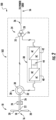
- a wind turbine power system 100 which includes the wind turbine 10 and associated power system 102, is illustrated.
- the blades 20 transform wind energy into a mechanical rotational torque that rotatably drives a low-speed shaft 22.
- the low-speed shaft 22 is configured to drive a gearbox 24 (where present) that subsequently steps up the low rotational speed of the low-speed shaft 22 to drive a high-speed shaft 26 at an increased rotational speed.
- the high-speed shaft 26 is generally rotatably coupled to a generator 28 (such as a doubly-fed induction generator or DFIG) so as to rotatably drive a generator rotor 30.
- a generator 28 such as a doubly-fed induction generator or DFIG
- a rotating magnetic field may be induced by the generator rotor 30 and a voltage may be induced within a generator stator 32 that is magnetically coupled to the generator rotor 30.
- the associated electrical power can be transmitted from the generator stator 32 to a main three-winding transformer 34 that is connected to an electrical grid at a POI 56 via a grid breaker 36.
- the main transformer 34 steps up the voltage amplitude of the electrical power such that the transformed electrical power may be further transmitted to the electrical grid.
- the generator 28 may be electrically coupled to a bidirectional power converter 38 that includes a rotor-side converter 40 joined to a line-side converter 42 via a regulated DC link 44.
- the rotor-side converter 40 converts the AC power provided from the generator rotor 30 into DC power and provides the DC power to the DC link 44.
- the line side converter 42 converts the DC power on the DC link 44 into AC output power suitable for the electrical grid.
- the AC power from the power converter 38 can be combined with the power from the generator stator 32 to provide multi-phase power (e.g. three-phase power) having a frequency maintained substantially at the frequency of the electrical grid (e.g. 50 Hz/60 Hz).
- power system 102 can include a turbine level controller 224 (shown in FIG. 3 ).
- the turbine level controller 224 can be a control, such as the controller shown and described in FIG. 4 .
- the illustrated three-winding transformer 34 can have (1) a 33 kilovolt (kV) medium voltage (MV) primary winding 33 connected to the electrical grid, (2) a 6 to 13.8 kV MV secondary winding 35 connected to the generator stator 32, and (3) a 690 to 900 volt (V) low-voltage (LV) tertiary winding 37 connected to the line-side power converter 42.
- kV medium voltage
- MV medium voltage
- LV low-voltage
- the wind farm electrical power system 200 can include a plurality of wind turbine power systems 100, connected to an electrical grid via a POI 56.
- the wind farm electrical power system 200 may include at least two clusters 204 to form an electrical power system 200.
- Individual wind turbine power systems 100 including of a plurality of wind turbines 10 may be arranged in predetermined geographic locations and electrically connected together to form a wind farm 202.
- each wind turbine power system 100 can be transmitted to a main line 206 via one or more cluster lines 220.
- Each wind turbine power system 100 can be connected or disconnected to the one or more cluster lines 220 via one or more switches or breakers 222.
- Wind turbine power systems 100 may be arranged into a plurality of groups (or clusters) 204 with each group separately connected to a main line 206 via switches 208, 210, 212, respectively.
- each cluster 204 may be connected to a separate transformer 214, 216, 218 via switches 208, 210, 212, respectively, for stepping up the voltage amplitude of the electrical power from each cluster 204 such that the transformed electrical power may be further transmitted to the electrical grid.
- the transformers 214, 216, 218 are connected to a main line 206 that combines the voltage from each cluster 204 before sending the power to the grid via a POI 56.
- the POI 56 can be a breaker, switch or other known method of connection to an electrical grid.
- Each wind turbine power system 100 can include a voltage regulator 228 (i.e., a wind turbine terminal voltage regulator). As such, the voltage regulator 228 regulates the voltage which is output by each wind turbine power system 100. Further, the voltage regulator 228 can be in electrical communication with turbine controller 224 or central master controller 226. Thus, the turbine-level controller 224 or central master controller 226 can deliver a voltage regulator gain command (V CMD ) to one or more of the voltage regulators 228 which in turn dictates the amount of power distributed to the POI 56 via cluster lines 220.
- V CMD voltage regulator gain command
- Each wind turbine power system 100 can include one or more controllers, such as turbine controller 224.
- the turbine controller 224 can be configured to control the components of the wind turbine power system 100, including switches 222 or voltage regulator 228, and/or implement some or all the method steps as described herein.
- the turbine controller 224 can be located on or within each wind turbine 10 or can be located remotely from each wind turbine 10.
- the turbine controller 224 can be part of or included with one or more of the other controllers associated with wind turbine power system 100 and/or the wind farm electrical power system 200.
- the turbine controller 224 can operate switches 222 to connect or disconnect the one or more wind turbine power systems 100 from the cluster lines 220 and control the voltage regulator 228, such as the voltage regulator gain, based at least in part on the power required at the POI 56, and/or based, at least in part, on characteristics of the wind turbine power system 100, wind farm electrical power system 200, and/or characteristics of the wind turbines 10 (e.g., wind turbine size, location, age, maintenance status), the electrical grid (e.g., strength or condition of the grid, strength or condition of the connection of the wind farm or wind turbine to the grid, grid architecture, grid location), the load on the grid (e.g., loads that are heavy or variable) and/or the environmental conditions (e.g., the wind conditions for the one or more wind turbines).
- the electrical grid e.g., strength or condition of the grid, strength or condition of the connection of the wind farm or wind turbine to the grid, grid architecture, grid location
- the load on the grid e.g., loads that are heavy or variable
- the wind farm electrical power system 200 can include one or more controllers, such as central master controller 226.
- the central master controller 226 can be configured to control the components of the wind farm electrical power system 200, including switches 208, 210 and 212, voltage regulators 228, communicate with one or more other controllers, such as turbine-level controllers 224, and/or implement some or all the method steps as described herein.
- the central master controller 226 can be located within the geographic area of the wind farm electrical power system 200, or any portion thereof, or can be located remotely from the wind farm electrical power system 200, or any portion thereof.
- the central master controller 226 can be part of or included with one or more of the other controllers associated with one or more of the wind turbine power systems 100 and/or the wind farm electrical power system 200.
- Each of the clusters 204, wind turbine power systems 100, or turbine-level controllers 224 may be communicatively coupled with a Central master controller 226.
- the central master controller 226 can generate and send control signals to turbine controller 224 to operate switches 222 to connect or disconnect the one or more wind turbine power systems 100 from the cluster lines 220 based at least in part on the power required at the POI 56.
- the central master controller 226 can generate and send control signals to voltage regulators 228 to operate or control the voltage regulators 228 and control the amount of power delivered to the POI from the one or more wind turbine power systems 100 through the cluster lines 220 based at least in part on the power required at the POI 56.
- the central master controller 226 can generate and send control signals to switches 208, 210 and/or 212 and/or voltage regulators 228 to regulate the power delivered to the POI 56, based at least in part on the power required at the POI 56, and/or based, at least in part, on characteristics of the wind turbine power system 100, wind farm electrical power system 200, and/or characteristics of the wind turbines 10 (e.g., wind turbine size, location, age, maintenance status), the electrical grid (e.g., strength or condition of the grid, strength or condition of the connection of the wind farm or wind turbine to the grid, grid architecture, grid location), the load on the grid (e.g., loads that are heavy or variable) and/or the environmental conditions (e.g., the wind conditions for the one or more wind turbines).
- characteristics of the wind turbine power system 100, wind farm electrical power system 200, and/or characteristics of the wind turbines 10 e.g., wind turbine size, location, age, maintenance status
- the electrical grid e.g., strength or condition of
- the controller 400 can be a turbine-level controller 224 or central master controller 226. Further, as shown, the controller 400 can include one or more processor(s) 402 and associated memory device(s) 404 configured to perform a variety of computer-implemented functions (e.g., performing the methods, steps, calculations and the like and storing relevant data as disclosed herein).
- processor(s) 402 and associated memory device(s) 404 configured to perform a variety of computer-implemented functions (e.g., performing the methods, steps, calculations and the like and storing relevant data as disclosed herein).
- the memory device 404 may also store date relevant to certain characteristics of the wind turbine power system 100, wind farm electrical power system 200, and/or characteristics of the wind turbines 10 (e.g., wind turbine size, location, age, maintenance status), the electrical grid (e.g., strength or condition of the grid, strength or condition of the connection of the wind farm or wind turbine to the grid, grid architecture, grid location), the load on the grid (e.g., loads that are heavy or variable) and/or the environmental conditions (e.g., the wind conditions for the one or more wind turbines).
- characteristics of the wind turbine power system 100, wind farm electrical power system 200, and/or characteristics of the wind turbines 10 e.g., wind turbine size, location, age, maintenance status
- the electrical grid e.g., strength or condition of the grid, strength or condition of the connection of the wind farm or wind turbine to the grid, grid architecture, grid location
- the load on the grid e.g., loads that are heavy or variable
- the environmental conditions e.g., the wind conditions for
- the controller 400 may include a communications module 406 to facilitate communications between the controller and the various components of the wind turbine power system 100, the wind farm electrical power system 200 and/or the central master controller 226, including communication between central master controller 226 and turbine-level controller 224.
- the communications module 406 may include a sensor interface 408 (e.g., one or more analog-to-digital converters) to permit signals transmitted from one or more sensors 410, 412 and 414 to be converted into signals that can be understood and processed by the processors 402.
- Sensors 410, 412 and 414 can be used to measure, ascertain or gather data regarding characteristics of the wind turbine power system 100, wind farm electrical power system 200, and/or characteristics of the wind turbines 10 (e.g., wind turbine size, location, age, maintenance status), the electrical grid (e.g., strength or condition of the grid, strength or condition of the connection of the wind farm or wind turbine to the grid, grid architecture, grid location), the load on the grid (e.g., loads that are heavy or variable) and/or the environmental conditions (e.g., the wind conditions for the one or more wind turbines).
- characteristics of the wind turbine power system 100, wind farm electrical power system 200, and/or characteristics of the wind turbines 10 e.g., wind turbine size, location, age, maintenance status
- the electrical grid e.g., strength or condition of the grid, strength or condition of the connection of the wind farm or wind turbine to the grid, grid architecture, grid location
- the load on the grid e.g., loads that are heavy or variable
- the environmental conditions
- the controller 400 can also include a user interface 416.
- the user interface 416 can have various configurations and controls can be mounted or in user interface 416.
- the user interface 416 can also be located within the geographic area of the wind farm electrical power system 200, or any portion thereof, or can be located remotely from the wind farm electrical power system 200, or any portion thereof.
- the user interface 416 can include an input component 418.
- Input component 418 can be, for instance, a capacitive touch screen.
- the input component 418 can allow for the selective activation, adjustment or control of wind farm controller 226 and turbine controller 224, as well as any timer features or other user adjustable inputs.
- the user interface 416 can include a display component, such as a digital or analog display device designed to provide operation feedback to a user.
- the sensors 410, 412 and 414 may be communicatively coupled to the communications module 406 using any suitable means.
- the sensors 410, 412 and 414 may be coupled to the sensor interface 408 via a wired connection.
- the sensors 410, 412 and 414 may be coupled to the sensor interface 408 via a wireless connection, such as by using any suitable wireless communications protocol known in the art.
- the processor 402 may be configured to receive one or more signals from the sensors 410, 412 and 414.
- Sensors 410, 412 and 414 can be part of or included with one or more of the other controllers associated with one or more of the wind turbine power systems 100 and/or the wind farm electrical power system 200.
- Sensors 410, 412 and 414 can also be located within the geographic area of the wind farm electrical power system 200, or any portion thereof, or can be located remotely from the wind farm electrical power system 200, or any portion thereof.
- sensors 410, 412 and 414 can be any number or type of voltage and/or electric current sensors may be employed within the wind turbine power systems 100 and at any location.
- the sensors may be current transformers, shunt sensors, rogowski coils, Hall Effect current sensors, Micro Inertial Measurement Units (MIMUs), or similar, and/or any other suitable voltage or electric current sensors now known or later developed in the art.
- the one or more controllers such as wind farm controller 226 and turbine controller 224, are configured to receive one or more voltage and/or electric current feedback signals from sensors 410, 412 and 414.
- processor refers not only to integrated circuits referred to in the art as being included in a computer, but also refers to a controller, a microcontroller, a microcomputer, a programmable logic controller (PLC), an application specific integrated circuit, and other programmable circuits.
- the processor 402 is also configured to compute advanced control algorithms and communicate to a variety of Ethernet or serial-based protocols (Modbus, OPC, CAN, etc.).
- the memory device(s) 404 may generally include memory element(s) including, but not limited to, computer readable medium (e.g., random access memory (RAM)), computer readable non-volatile medium (e.g., a flash memory), a floppy disk, a compact disc-read only memory (CD-ROM), a magnetooptical disk (MOD), a digital versatile disc (DVD) and/or other suitable memory elements.
- RAM random access memory
- RAM computer readable non-volatile medium
- CD-ROM compact disc-read only memory
- MOD magnetooptical disk
- DVD digital versatile disc
- Such memory device(s) 140 may generally be configured to store suitable computer-readable instructions that, when implemented by the processor(s) 402, configure the controller to perform the various functions as described herein.
- FIGS. 5 and 6 a method 500 and system 600 for controlling a wind farm electrical power system according to the present disclosure are illustrated, respectively. More specifically, FIG. 5 illustrates a flow chart of one embodiment of a method 500 for controlling a wind farm electrical power system according to the present disclosure, whereas FIG. 6 illustrates a schematic diagram of one embodiment of a system 600 for controlling a wind farm electrical power system according to the present disclosure.
- the method 500 and system 600 will be described herein with reference to the wind turbine 10, the wind turbine power system 100, the wind farm electrical power system 200, and the various controllers illustrated in FIGS. 1-4 .
- the disclosed method 500 and system 600 may be implemented with wind turbines and wind farms having any other suitable configurations.
- FIG. 5 depicts steps performed in a particular order for purposes of illustration and discussion, the methods discussed herein are not limited to any particular order or arrangement.
- controllers such as central master controller 226 and/or turbine-level controller 224, and by the other devices included with a wind turbine power system 100 and/or wind farm electrical power system 200.
- the method 500 includes receiving, e.g. via the master controller 226, one or more electrical signals associated with the point of interconnection 56 for a frequency domain.
- a preprocessor 602 of the controller 226 may receive the electrical signal(s) 603 from the point of interconnection 56.
- the electrical signal(s) may include any one of or a combination of the following: phase voltage, phase current, active power, and/or reactive power at the point of interconnection 56.
- the method 500 may include measuring the electrical signal(s) via at least one sensor, such as one of sensors 410, 412, 414.
- the method 500 may include determining or estimating the electrical signal(s) via a computer-implemented model of the controller 226.
- the method 500 includes estimating, via an estimator 604 of the controller 226, a voltage sensitivity (e.g. a grid strength) of the electrical grid using the electrical signal(s).
- a voltage sensitivity e.g. a grid strength
- the method 500 may include processing the electrical signal(s) associated with the point of interconnection 56 prior to estimating the voltage sensitivity.
- the preprocessor 602 may be capable of filtering, sorting, or similar or combinations thereof the electrical signal(s).
- the controller 226 is configured to estimate the voltage sensitivity of the electrical grid by modeling the electrical grid as a linear time-invariant system for the frequency domain (e.g. having short measurement windows and small, linear signal disturbances). For example, as shown in FIGS. 7 and 8 , the controller 226 may be configured to generate frequency domains 700, 800 for the electrical signal(s). More particularly, as shown, FIG. 7 illustrates frequency domains for voltage and reactive power, whereas FIG. 8 illustrates frequency domains for voltage and active power. Since the wind farm electrical power system 200 will have perturbations in active power due to wind speed variations and frequencies of perturbations exist in active and reactive power for individual wind farms, the controller 226 can easily monitor the frequency domain for perturbations. More specifically, a perturbation in active or reactive power at a particular frequency translates to a voltage response at the same frequency.
- the controller 226 is configured to identify corresponding response pairs of voltage and reactive power (as indicated via arrows 702, 704).
- the controller 226 is configured to identify corresponding response pairs of voltage and active power (as indicated via arrows 802, 804).
- the controller 226 is configured to group perturbations of active power and/or reactive power with the phase voltage for the frequency domain.
- the controller 226 can determine whether the perturbations correspond to the wind farm electrical power system 200 or to neighboring wind farm electrical power systems.
- the controller 226 may identify perturbations that are not in groups or pairs as those corresponding to perturbations from neighboring wind farm electrical power systems. Accordingly, the controller 226 can remove perturbations (such as perturbations 706, 806) corresponding to neighboring wind farm electrical power systems to decouple an effect of the perturbations 706, 806 on the voltage sensitivity.
- the system 600 may also include a post processor 608 for processing the electrical signal(s) associated with the point of interconnection 56 after estimating the voltage sensitivity of the electrical grid e.g. to determine an error analysis of the parameter(s) of the voltage regulator(s) 228.
- the method 500 includes dynamically controlling a voltage of the wind farm electrical power system 200 at the point of interconnection 56 based on the voltage sensitivity.
- the controller 226 may include a voltage controller 606 configured to dynamically control the voltage of the wind farm electrical power system 200 by varying at least one parameter of one or more of the voltage regulators 228 of the individual wind turbine power systems 100 of the wind farm 200 to avoid instability of the electrical grid.
- the parameter(s) may include, for example, a regulator gain, an active power set point, a reactive power set point, or combinations thereof, as well as any other suitable parameter.
- control diagrams 900, 1000 of various embodiments for varying the reactive power and active power set points (Q SP and P SP ), respectively, of one or more of the voltage regulators 228 of the individual wind turbine power systems 100 of the wind farm 200 to avoid instability of the electrical grid are illustrated.
- the control diagrams 900, 1000 may include proportional integral (PI) controllers 906, 1006.
- PI proportional integral
- the control schemes 900, 100 may be capable of dynamically tuning the regulator gains associated with the PI controllers 906, 1006. More particularly, as shown, the control diagrams illustrate implementation of feedforward voltage control based on outputs 902, 1002 of the estimator 604.
- ⁇ Q and ⁇ P may be calculated as a function of the voltage sensitivities (e.g. dQ/dV, dP/dV) from the estimator 604. More specifically, as shown at block 904 in FIG. 9 , ⁇ Q may be calculated as a function of, at least, a gain ( ⁇ 1 ) that can be tuned to a particular wind farm, the voltage setpoint (V sp ), the actual voltage (V act ), and the voltage sensitivity (dQ/dV) from the estimator 604. Similarly, as shown at block 1004 in FIG.
- ⁇ P may be calculated as a function of, at least, a gain ( ⁇ 2 ) that can be tuned to a particular wind farm, the voltage setpoint (V sp ), the actual voltage (V act ), and the voltage sensitivity (dP/dV) from the estimator 604.
- ⁇ 1 and ⁇ 2 can be dynamically altered by a machine learning algorithm in the closed loop runs, depending on the post processor error analysis.
- the controller 226 is configured to distribute the adjusted set points for active and reactive power (Q SP and P SP ) to achieve the desired voltage response.
- the wind farms response can be recorded to process the data and provide the feedback to a machine learning-based algorithm to take further decisions.
- the system 600 may include a machine learning algorithm 610 that receives feedback 612 from the post processor 608 and trains the feedback 612.
- the machine learning algorithm 610 is configured to generate one or more control commands 614 for the estimator 604 of the controller 226 to continually update the estimator 604.
- control command(s) 614 may include the gains ⁇ 1 and ⁇ 2 used for clustering/grouping the frequency domain signals of the electrical signals measured as well as the thresholds set to filter out the unwanted frequency domain signals to be grouped.
- control command(s) 614 may include some adjustments to the pre-processor parameters such as the sampling window for the analysis, the number of samples considered at a time for estimation, etc.
- the machine learning algorithm 610 is configured to adjust any parameters described herein so as to reduce the error computed by the post processor (the error being the difference between the actual voltage measured and the voltage estimated using the voltage sensitivities). As such, a goal of the machine learning algorithm 610 is to make the system 600 adaptable and robust in case of weak grid situations.
- the response time of the estimator 604 may be faster than the controller 226, which is faster than the commands 614 coming from the machine learning algorithm 610.
- the machine learning algorithm 610 may be a trained neural network, a simple linear regression model, a random forest regression model, a support vector machine, or any suitable type of a supervised learning model based on the quality and quantity of data received. More specifically, in an embodiment, the method may include embedding a reinforcement learning technique in the machine learning algorithm 610.
- the one or more electrical signals comprise at least one of phase voltage, phase current, active power, and reactive power at the point of interconnection.
- the plurality of processors further comprises a pre-processor for processing the one or more electrical signals associated with the point of interconnection prior to estimating the voltage sensitivity.
- estimating the voltage sensitivity of the electrical grid using the one or more electrical signals further comprises:
- the plurality of processors further comprises a post-processor for processing the one or more electrical signals associated with the point of interconnection after dynamically controlling the voltage of the wind farm electrical power system based on the voltage sensitivity to determine an error analysis of the one or more parameters of the voltage regulator.
- the plurality of processors further comprises a machine learning algorithm configured to receive and train feedback from the post processor and generate one or more control commands for the estimator to continually update the estimator.
Claims (13)
- Verfahren zum Steuern eines elektrischen Windpark-Leistungssystems, wobei das elektrische Windpark-Leistungssystem eine Steuerung, eine Vielzahl von Windturbinen, die über einem Zusammenschaltungspunkt elektrisch mit einem elektrischen Netz verbunden sind, und wobei jede Windturbine einen Spannungsregler aufweist, wobei das Verfahren umfasst:Empfangen (502), über die Steuerung, eines oder mehrerer elektrischer Signale, die mit dem Zusammenschaltungspunkt in Verbindung sind, für einen Frequenzbereich;Schätzen (504), über einen Schätzer der Steuerung, einer Spannungsempfindlichkeit des elektrischen Netzes unter Verwendung des einen oder der mehreren elektrischen Signale; und,dynamisches Steuern (506) einer Spannung des elektrischen Windpark-Leistungssystems am Zusammenschaltungspunkt auf der Grundlage der Spannungsempfindlichkeit;wobei das eine oder die mehreren elektrischen Signale mindestens eines der folgenden Signale umfassen: Phasenspannung, Phasenstrom, Wirkleistung und Blindleistung am Zusammenschaltungspunkt;und wobei das Schätzen der Spannungsempfindlichkeit des elektrischen Netzes unter Verwendung des einen oder der mehreren elektrischen Signale ferner umfasst:Modellieren, über die Steuerung, des elektrischen Netzes als lineares zeitinvariantes System für den Frequenzbereich;Überwachen des Frequenzbereichs auf Störungen;Bestimmen, ob die Störungen mit dem elektrischen Windpark-Leistungssystem oder mit den benachbarten elektrischen Windpark-Leistungssystemen korrespondieren; und,Entfernen von Störungen, die mit benachbarten elektrischen Windpark-Leistungssystemen korrespondieren, um einen Effekt der Störungen auf die Spannungsempfindlichkeit zu entkoppeln.
- Verfahren nach einem der vorhergehenden Ansprüche, ferner umfassend mindestens eines von Folgendem: Messen des einen oder der mehreren elektrischen Signale über mindestens einen Sensor oder Bestimmen des einen oder der mehreren elektrischen Signale über ein computerimplementiertes Modell der Steuerung.
- Verfahren nach einem der vorhergehenden Ansprüche, ferner umfassend das Verarbeiten des einen oder der mehreren elektrischen Signale, die mit dem Zusammenschaltungspunkt in Verbindung sind, vor dem Schätzen der Spannungsempfindlichkeit, wobei die Verarbeitung des einen oder der mehreren elektrischen Signale mindestens eine Filterung oder Sortierung umfasst.
- Verfahren nach Anspruch 1, wobei das Bestimmen, ob die Störungen mit dem elektrischen Windpark-Leistungssystem oder dem benachbarten elektrischen Windpark-Leistungssystem korrespondieren, ferner umfasst:Gruppieren von Störungen der Wirkleistung und/oder der Blindleistung mit der Phasenspannung für den Frequenzbereich; und,Entfernen von Störungen, die nicht in Gruppen auftreten.
- Verfahren nach einem der vorhergehenden Ansprüche, wobei die dynamische Steuerung der Spannung des elektrischen Windpark-Leistungssystems auf der Grundlage der Spannungsempfindlichkeit ferner umfasst:
Verändern mindestens eines Parameters eines oder mehrerer Spannungsregler, um eine Instabilität des elektrischen Netzes zu vermeiden. - Verfahren nach Anspruch 5, wobei der mindestens eine Parameter mindestens eine Reglerverstärkung, einen Wirkleistungssollwert oder einen Blindleistungssollwert umfasst.
- Verfahren nach Anspruch 5, ferner umfassend das Verarbeiten des einen oder der mehreren elektrischen Signale, die mit dem Zusammenschaltungspunkt in Verbindung sind, über einen Postprozessor der Steuerung, nachdem die Spannung des elektrischen Windpark-Leistungssystem auf der Grundlage der Spannungsempfindlichkeit dynamisch gesteuert wurde, um eine Fehleranalyse des einen oder der mehreren Parameter des Spannungsreglers zu bestimmen.
- Verfahren nach Anspruch 7, ferner umfassend:Empfangen, über einen maschinellen Lernalgorithmus der Steuerung, von Rückmeldungen vom Postprozessor; und,Trainieren des Feedbacks über den maschinellen Lernalgorithmus.
- Verfahren nach Anspruch 8, ferner umfassend das Erzeugen eines oder mehrerer Steuerbefehle für den Schätzer der Steuerung unter Verwendung der Ausgaben des Algorithmus für maschinelles Lernen, um den Schätzer kontinuierlich zu aktualisieren.
- Verfahren nach Anspruch 9, wobei eine Reaktionszeit des Schätzers schneller ist als die der Steuerung und eine Reaktionszeit der Steuerung schneller ist als die Erzeugung des einen oder der mehreren Steuerbefehle aus dem Algorithmus für maschinelles Lernen.
- Verfahren nach Anspruch 8, wobei der maschinelle Lernalgorithmus ein trainiertes neuronales Netzwerk, ein einfaches lineares Regressionsmodell, ein Random-Forest-Regressionsmodell oder eine Support-Vector-Maschine umfasst.
- Verfahren nach Anspruch 8, ferner umfassend das Einbetten einer Verstärkungslerntechnik in den maschinellen Lernalgorithmus.
- System zur Steuerung eines elektrischen Windpark-Leistungssystems, wobei das elektrische Windpark-Leistungssystems eine Vielzahl von Windturbinen umfasst, die über einen Zusammenschaltungspunkt elektrisch mit einem elektrischen Netz in Verbindung sind, und wobei jede Windturbine einen Spannungsregler umfasst, wobei das System umfasst:
eine Steuerung, die eine Vielzahl von Prozessoren umfasst, wobei die Vielzahl von Prozessoren mindestens einen Schätzer umfasst, wobei der Schätzer so konfiguriert ist, dass er Operationen durchführt, wobei die Operationen umfassen:Empfangen (502) eines oder mehrerer elektrischer Signale, die mit dem Zusammenschaltungspunkt verbunden sind, für einen Frequenzbereich;Schätzen (504) einer Spannungsempfindlichkeit des elektrischen Netzes unter Verwendung des einen oder der mehreren elektrischen Signale; und,wobei die Steuerung so konfiguriert ist, dass sie eine Spannung des elektrischen Windpark-Leistungssystems am Zusammenschaltungspunkt auf der Grundlage der Spannungsempfindlichkeit dynamisch steuert (506), indem sie mindestens einen Parameter eines oder mehrerer der Spannungsregler ändert, um eine Instabilität des elektrischen Netzes zu vermeiden;und wobei das Schätzen der Spannungsempfindlichkeit des elektrischen Netzes unter Verwendung des einen oder der mehreren elektrischen Signale ferner umfasst:Modellieren des elektrischen Netzes über die Steuerung als lineares zeitinvariantes System für den Frequenzbereich;Überwachen des Frequenzbereichs auf Störungen;Bestimmen, ob die Störungen mit dem elektrischen Windpark-Leistungssystem oder benachbarten elektrischen Windpark-Leistungssystem korrespondieren; und,Entfernen von Störungen, die mit benachbarten elektrischen Windpark-Stromsystemen korrespondieren, um eine Wirkung der Störungen auf die Spannungsempfindlichkeit zu entkoppeln.
Applications Claiming Priority (1)
| Application Number | Priority Date | Filing Date | Title |
|---|---|---|---|
| US16/734,914 US11233402B2 (en) | 2020-01-06 | 2020-01-06 | System and method for stabilizing weak grids with one or more wind farms connected thereto |
Publications (2)
| Publication Number | Publication Date |
|---|---|
| EP3846302A1 EP3846302A1 (de) | 2021-07-07 |
| EP3846302B1 true EP3846302B1 (de) | 2024-04-10 |
Family
ID=73856449
Family Applications (1)
| Application Number | Title | Priority Date | Filing Date |
|---|---|---|---|
| EP20216151.9A Active EP3846302B1 (de) | 2020-01-06 | 2020-12-21 | System und verfahren zum stabilisieren von schwachen netzen mit einer oder mehreren daran angeschlossenen windenergieanlagen |
Country Status (3)
| Country | Link |
|---|---|
| US (1) | US11233402B2 (de) |
| EP (1) | EP3846302B1 (de) |
| CN (1) | CN113078673A (de) |
Families Citing this family (1)
| Publication number | Priority date | Publication date | Assignee | Title |
|---|---|---|---|---|
| CA3235462A1 (en) * | 2021-10-15 | 2023-04-20 | General Electric Technology Gmbh | Adaptive power grid management system |
Family Cites Families (17)
| Publication number | Priority date | Publication date | Assignee | Title |
|---|---|---|---|---|
| US7839024B2 (en) | 2008-07-29 | 2010-11-23 | General Electric Company | Intra-area master reactive controller for tightly coupled windfarms |
| US8041465B2 (en) | 2008-10-09 | 2011-10-18 | General Electric Company | Voltage control at windfarms |
| WO2013160486A2 (de) * | 2012-04-27 | 2013-10-31 | Repower Systems Se | Windpark mit schneller lokaler blindleistungsregelung |
| DE102012212366A1 (de) | 2012-07-13 | 2014-01-30 | Wobben Properties Gmbh | Verfahren zum Steuern eines elektrischen Erzeugers |
| DE102012212364A1 (de) | 2012-07-13 | 2014-01-16 | Wobben Properties Gmbh | Verfahren und Vorrichtung zum Einspeisen elektrischer Energie in ein elektrisches Versorgungsnetz |
| US9190845B2 (en) | 2012-07-17 | 2015-11-17 | Siemens Aktiengesellschaft | Method and apparatus for adaptively controlling wind park turbines |
| DE102013208410A1 (de) | 2013-05-07 | 2014-11-13 | Wobben Properties Gmbh | Verfahren zum Einspeisen elektrischer Leistung in ein elektrisches Versorgungsnetz |
| DE102013208474A1 (de) | 2013-05-08 | 2014-11-13 | Wobben Properties Gmbh | Verfahren zum Einspeisen elektrischer Leistung in ein elektrisches Versorgungsnetz |
| US9541062B2 (en) | 2013-11-20 | 2017-01-10 | Siemens Aktiengesellschaft | Method of operating a wind park |
| US9458831B2 (en) * | 2015-02-18 | 2016-10-04 | General Electric Company | Determining reactive power capability of a renewable energy system |
| US9831810B2 (en) | 2015-03-10 | 2017-11-28 | General Electric Company | System and method for improved reactive power speed-of-response for a wind farm |
| US10027118B2 (en) * | 2016-05-19 | 2018-07-17 | General Electric Company | System and method for balancing reactive power loading between renewable energy power systems |
| GB201612181D0 (en) | 2016-07-09 | 2016-08-24 | Smiths Medical Int Ltd | Tracheostomy tube assemblies and inner cannulae |
| US10333308B2 (en) | 2016-08-15 | 2019-06-25 | Nec Corporation | Two-level predictive based reactive power coordination and voltage restoration for microgrids |
| WO2018115431A1 (en) * | 2016-12-23 | 2018-06-28 | Danmarks Tekniske Universitet | Combined active and reactive power control in an operation of a wind farm |
| US10330081B2 (en) * | 2017-02-07 | 2019-06-25 | International Business Machines Corporation | Reducing curtailment of wind power generation |
| CN108879705B (zh) | 2018-06-11 | 2022-07-29 | 国电南瑞科技股份有限公司 | 计及风功率不确定性的风电汇集区域无功电压控制方法 |
-
2020
- 2020-01-06 US US16/734,914 patent/US11233402B2/en active Active
- 2020-12-21 EP EP20216151.9A patent/EP3846302B1/de active Active
-
2021
- 2021-01-06 CN CN202110013148.9A patent/CN113078673A/zh active Pending
Also Published As
| Publication number | Publication date |
|---|---|
| EP3846302A1 (de) | 2021-07-07 |
| US20210210959A1 (en) | 2021-07-08 |
| US11233402B2 (en) | 2022-01-25 |
| CN113078673A (zh) | 2021-07-06 |
Similar Documents
| Publication | Publication Date | Title |
|---|---|---|
| EP3619786B1 (de) | System und verfahren zur blindleistungsregelung eines windparks | |
| US10804707B2 (en) | Systems and methods for dynamic management of wind turbines providing reactive power | |
| EP3641088B1 (de) | Systeme und verfahren zum resonanzmanagement in leistungssystemen von windturbinen | |
| EP3846302B1 (de) | System und verfahren zum stabilisieren von schwachen netzen mit einer oder mehreren daran angeschlossenen windenergieanlagen | |
| US10554044B2 (en) | System and method for optimizing reactive power generation of a wind farm | |
| US20220333575A1 (en) | System and method for adjusting reactive power response of one or more wind turbines of a wind farm during a communications fault | |
| EP3451481B1 (de) | System und verfahren zum verhindern eines spannungseinbruchs von mit einem stromnetz verbundenen windkraftanlagen | |
| EP3639341B1 (de) | Stromuntersysteme und verfahren zur steuerung davon | |
| US11451057B2 (en) | Systems and methods for controlling electrical power systems connected to a power grid | |
| EP3462562A1 (de) | System und verfahren zur steuerung von clusterbasierten windparks | |
| CA3211858A1 (en) | System and method for reducing farm-level power oscillations in the grid induced by a wind farm | |
| CN115940195A (zh) | 用于在功率生成系统中进行功率振荡阻尼的系统和方法 |
Legal Events
| Date | Code | Title | Description |
|---|---|---|---|
| PUAI | Public reference made under article 153(3) epc to a published international application that has entered the european phase |
Free format text: ORIGINAL CODE: 0009012 |
|
| STAA | Information on the status of an ep patent application or granted ep patent |
Free format text: STATUS: THE APPLICATION HAS BEEN PUBLISHED |
|
| AK | Designated contracting states |
Kind code of ref document: A1 Designated state(s): AL AT BE BG CH CY CZ DE DK EE ES FI FR GB GR HR HU IE IS IT LI LT LU LV MC MK MT NL NO PL PT RO RS SE SI SK SM TR |
|
| STAA | Information on the status of an ep patent application or granted ep patent |
Free format text: STATUS: REQUEST FOR EXAMINATION WAS MADE |
|
| 17P | Request for examination filed |
Effective date: 20220105 |
|
| RBV | Designated contracting states (corrected) |
Designated state(s): AL AT BE BG CH CY CZ DE DK EE ES FI FR GB GR HR HU IE IS IT LI LT LU LV MC MK MT NL NO PL PT RO RS SE SI SK SM TR |
|
| P01 | Opt-out of the competence of the unified patent court (upc) registered |
Effective date: 20230530 |
|
| GRAP | Despatch of communication of intention to grant a patent |
Free format text: ORIGINAL CODE: EPIDOSNIGR1 |
|
| STAA | Information on the status of an ep patent application or granted ep patent |
Free format text: STATUS: GRANT OF PATENT IS INTENDED |
|
| INTG | Intention to grant announced |
Effective date: 20231107 |
|
| RAP1 | Party data changed (applicant data changed or rights of an application transferred) |
Owner name: GENERAL ELECTRIC RENOVABLES ESPANA, S.L. |
|
| GRAS | Grant fee paid |
Free format text: ORIGINAL CODE: EPIDOSNIGR3 |
|
| GRAA | (expected) grant |
Free format text: ORIGINAL CODE: 0009210 |
|
| STAA | Information on the status of an ep patent application or granted ep patent |
Free format text: STATUS: THE PATENT HAS BEEN GRANTED |
|
| AK | Designated contracting states |
Kind code of ref document: B1 Designated state(s): AL AT BE BG CH CY CZ DE DK EE ES FI FR GB GR HR HU IE IS IT LI LT LU LV MC MK MT NL NO PL PT RO RS SE SI SK SM TR |
|
| REG | Reference to a national code |
Ref country code: GB Ref legal event code: FG4D |
|
| REG | Reference to a national code |
Ref country code: CH Ref legal event code: EP |
|
| REG | Reference to a national code |
Ref country code: DE Ref legal event code: R096 Ref document number: 602020028683 Country of ref document: DE |