EP3845987B1 - Temperature abnormality detection system, temperature abnormality detection method, and program - Google Patents
Temperature abnormality detection system, temperature abnormality detection method, and program Download PDFInfo
- Publication number
- EP3845987B1 EP3845987B1 EP19877922.5A EP19877922A EP3845987B1 EP 3845987 B1 EP3845987 B1 EP 3845987B1 EP 19877922 A EP19877922 A EP 19877922A EP 3845987 B1 EP3845987 B1 EP 3845987B1
- Authority
- EP
- European Patent Office
- Prior art keywords
- temperature
- sensor
- target device
- abnormality detection
- casing
- Prior art date
- Legal status (The legal status is an assumption and is not a legal conclusion. Google has not performed a legal analysis and makes no representation as to the accuracy of the status listed.)
- Active
Links
Images




Classifications
-
- G—PHYSICS
- G01—MEASURING; TESTING
- G01K—MEASURING TEMPERATURE; MEASURING QUANTITY OF HEAT; THERMALLY-SENSITIVE ELEMENTS NOT OTHERWISE PROVIDED FOR
- G01K3/00—Thermometers giving results other than momentary value of temperature
- G01K3/08—Thermometers giving results other than momentary value of temperature giving differences of values; giving differentiated values
- G01K3/14—Thermometers giving results other than momentary value of temperature giving differences of values; giving differentiated values in respect of space
-
- G—PHYSICS
- G05—CONTROLLING; REGULATING
- G05B—CONTROL OR REGULATING SYSTEMS IN GENERAL; FUNCTIONAL ELEMENTS OF SUCH SYSTEMS; MONITORING OR TESTING ARRANGEMENTS FOR SUCH SYSTEMS OR ELEMENTS
- G05B23/00—Testing or monitoring of control systems or parts thereof
- G05B23/02—Electric testing or monitoring
- G05B23/0205—Electric testing or monitoring by means of a monitoring system capable of detecting and responding to faults
- G05B23/0218—Electric testing or monitoring by means of a monitoring system capable of detecting and responding to faults characterised by the fault detection method dealing with either existing or incipient faults
- G05B23/0224—Process history based detection method, e.g. whereby history implies the availability of large amounts of data
- G05B23/0227—Qualitative history assessment, whereby the type of data acted upon, e.g. waveforms, images or patterns, is not relevant, e.g. rule based assessment; if-then decisions
- G05B23/0235—Qualitative history assessment, whereby the type of data acted upon, e.g. waveforms, images or patterns, is not relevant, e.g. rule based assessment; if-then decisions based on a comparison with predetermined threshold or range, e.g. "classical methods", carried out during normal operation; threshold adaptation or choice; when or how to compare with the threshold
-
- G—PHYSICS
- G01—MEASURING; TESTING
- G01J—MEASUREMENT OF INTENSITY, VELOCITY, SPECTRAL CONTENT, POLARISATION, PHASE OR PULSE CHARACTERISTICS OF INFRARED, VISIBLE OR ULTRAVIOLET LIGHT; COLORIMETRY; RADIATION PYROMETRY
- G01J5/00—Radiation pyrometry, e.g. infrared or optical thermometry
- G01J5/0066—Radiation pyrometry, e.g. infrared or optical thermometry for hot spots detection
-
- G—PHYSICS
- G01—MEASURING; TESTING
- G01J—MEASUREMENT OF INTENSITY, VELOCITY, SPECTRAL CONTENT, POLARISATION, PHASE OR PULSE CHARACTERISTICS OF INFRARED, VISIBLE OR ULTRAVIOLET LIGHT; COLORIMETRY; RADIATION PYROMETRY
- G01J5/00—Radiation pyrometry, e.g. infrared or optical thermometry
- G01J5/0096—Radiation pyrometry, e.g. infrared or optical thermometry for measuring wires, electrical contacts or electronic systems
-
- G—PHYSICS
- G01—MEASURING; TESTING
- G01J—MEASUREMENT OF INTENSITY, VELOCITY, SPECTRAL CONTENT, POLARISATION, PHASE OR PULSE CHARACTERISTICS OF INFRARED, VISIBLE OR ULTRAVIOLET LIGHT; COLORIMETRY; RADIATION PYROMETRY
- G01J5/00—Radiation pyrometry, e.g. infrared or optical thermometry
- G01J5/02—Constructional details
- G01J5/06—Arrangements for eliminating effects of disturbing radiation; Arrangements for compensating changes in sensitivity
- G01J5/064—Ambient temperature sensor; Housing temperature sensor; Constructional details thereof
-
- G—PHYSICS
- G01—MEASURING; TESTING
- G01K—MEASURING TEMPERATURE; MEASURING QUANTITY OF HEAT; THERMALLY-SENSITIVE ELEMENTS NOT OTHERWISE PROVIDED FOR
- G01K3/00—Thermometers giving results other than momentary value of temperature
- G01K3/005—Circuits arrangements for indicating a predetermined temperature
-
- G—PHYSICS
- G05—CONTROLLING; REGULATING
- G05B—CONTROL OR REGULATING SYSTEMS IN GENERAL; FUNCTIONAL ELEMENTS OF SUCH SYSTEMS; MONITORING OR TESTING ARRANGEMENTS FOR SUCH SYSTEMS OR ELEMENTS
- G05B23/00—Testing or monitoring of control systems or parts thereof
- G05B23/02—Electric testing or monitoring
- G05B23/0205—Electric testing or monitoring by means of a monitoring system capable of detecting and responding to faults
- G05B23/0259—Electric testing or monitoring by means of a monitoring system capable of detecting and responding to faults characterized by the response to fault detection
- G05B23/0267—Fault communication, e.g. human machine interface [HMI]
- G05B23/027—Alarm generation, e.g. communication protocol; Forms of alarm
-
- G—PHYSICS
- G05—CONTROLLING; REGULATING
- G05B—CONTROL OR REGULATING SYSTEMS IN GENERAL; FUNCTIONAL ELEMENTS OF SUCH SYSTEMS; MONITORING OR TESTING ARRANGEMENTS FOR SUCH SYSTEMS OR ELEMENTS
- G05B23/00—Testing or monitoring of control systems or parts thereof
- G05B23/02—Electric testing or monitoring
- G05B23/0205—Electric testing or monitoring by means of a monitoring system capable of detecting and responding to faults
- G05B23/0259—Electric testing or monitoring by means of a monitoring system capable of detecting and responding to faults characterized by the response to fault detection
- G05B23/0286—Modifications to the monitored process, e.g. stopping operation or adapting control
- G05B23/0291—Switching into safety or degraded mode, e.g. protection and supervision after failure
-
- H—ELECTRICITY
- H02—GENERATION; CONVERSION OR DISTRIBUTION OF ELECTRIC POWER
- H02H—EMERGENCY PROTECTIVE CIRCUIT ARRANGEMENTS
- H02H1/00—Details of emergency protective circuit arrangements
- H02H1/0007—Details of emergency protective circuit arrangements concerning the detecting means
-
- H—ELECTRICITY
- H02—GENERATION; CONVERSION OR DISTRIBUTION OF ELECTRIC POWER
- H02H—EMERGENCY PROTECTIVE CIRCUIT ARRANGEMENTS
- H02H5/00—Emergency protective circuit arrangements for automatic disconnection directly responsive to an undesired change from normal non-electric working conditions with or without subsequent reconnection
- H02H5/04—Emergency protective circuit arrangements for automatic disconnection directly responsive to an undesired change from normal non-electric working conditions with or without subsequent reconnection responsive to abnormal temperature
-
- G—PHYSICS
- G05—CONTROLLING; REGULATING
- G05B—CONTROL OR REGULATING SYSTEMS IN GENERAL; FUNCTIONAL ELEMENTS OF SUCH SYSTEMS; MONITORING OR TESTING ARRANGEMENTS FOR SUCH SYSTEMS OR ELEMENTS
- G05B2219/00—Program-control systems
- G05B2219/10—Plc systems
- G05B2219/14—Plc safety
- G05B2219/14043—Detection of abnormal temperature
-
- G—PHYSICS
- G05—CONTROLLING; REGULATING
- G05B—CONTROL OR REGULATING SYSTEMS IN GENERAL; FUNCTIONAL ELEMENTS OF SUCH SYSTEMS; MONITORING OR TESTING ARRANGEMENTS FOR SUCH SYSTEMS OR ELEMENTS
- G05B2219/00—Program-control systems
- G05B2219/20—Pc systems
- G05B2219/26—Pc applications
- G05B2219/2659—Elevator
Definitions
- the present disclosure relates to a temperature abnormality detection system and a temperature abnormality detection method, and more particularly to a temperature abnormality detection system and a temperature abnormality detection method for detecting a temperature abnormality of a target device installed in various boards.
- the present disclosure also relates to a program for causing a computer to execute such a temperature abnormality detection method.
- a control board for controlling operation of an elevator includes first temperature detecting means that detects a temperature of a device (equipment) forming a first control power supply and generates a first detection signal when the detected temperature exceeds a predetermined first threshold value (temperature upper limit value).
- a first opening/closing means (supplying DC voltage to the first control power supply) is opened based on the first detection signal, thereby enabling early detection of a fire in the control board.
- EP 0 857 012 A1 relates to monitoring ventilation of integrated circuits in electronic apparatus.
- US 6 921 895 B1 discloses a sensor module comprising a radiation sensor, a temperature sensor and a circuit computing the difference between both sensors' output, to compensate temperature and provide object temperature dependent output.
- US 7 362 224 B2 discloses a thermal door sensor with least two thermally sensitive sensors provided in an array arrangement.
- Patent Document 1 JP 2009-067521 A
- a first threshold value (temperature upper limit value) Tul is set to a temperature slightly exceeding the saturation temperature Ts1 in summer (for example, 80°C) so as not to make false determinations in summer.
- the temperatures increase with passage of time from the operation start temperatures Ts0 and Tw0 in summer and winter, with larger heat generation than the temperature increase amounts at normal state ⁇ Tsinc and ⁇ Twinc, respectively (Temperature increase amounts at the temperature abnormal state are represented by ⁇ Tsinc' and ⁇ Twinc'.
- the temperatures reach higher temperatures Ts1' and Tw1' than those in the normal state, respectively.
- an object of the present disclosure is to provide a temperature abnormality detection system and a temperature abnormality detection method that can accurately detect a temperature abnormality of a target device installed in a board, regardless of the temperature of environment where the board is placed (for example, temperature by season). Further, an object of the present disclosure is to provide a program for causing a computer to execute such a temperature abnormality detection method.
- a temperature abnormality detection system according to the present invention is provided according to claim 1.
- the "target device” refers to a device that is a target of temperature measurement and may have a temperature increase during operation.
- the "board” includes various boards such as a switchboard, a control board, and a distribution board.
- the first temperature sensor measures the first temperature indicated by the target device installed in the board.
- the second temperature sensor measures the second temperature indicated by the ambient air around the target device.
- the abnormality determination unit calculates the temperature difference between the first temperature and the second temperature, and determines that the temperature abnormality of the target device has occurred when the temperature difference becomes the predetermined threshold value or more.
- the second temperature is the temperature indicated by the ambient air around the target device, it reflects the temperature of environment where the board is placed (for example, temperature by season). Therefore, by determining whether or not the temperature abnormality has occurred based on the temperature difference between the first temperature and the second temperature, influence of the temperature of the environment on a determination result is offset. Therefore, according to the temperature abnormality detection system of the present disclosure, it is possible to accurately detect the temperature abnormality of the target device installed in the board regardless of the temperature of the environment where the board is placed.
- a position where the second temperature is measured is a position inside a casing of the board.
- the second temperature is a temperature indicated by the ambient air around the target device in the casing of the board. Therefore, the temperature difference between the first temperature and the second temperature is a net temperature increase amount of the target device with respect to the ambient air around the target device. In response to this, when the temperature difference between the first temperature and the second temperature, that is, the net temperature increase amount of the target device becomes the predetermined threshold value or more, the abnormality determination unit determines that the temperature abnormality of the target device has occurred. Therefore, accuracy of determining the temperature abnormality is improved.
- the position where the second temperature is measured is a position away from the target device.
- the second temperature is a temperature at the position in the casing of the board and away from the target device. Therefore, the second temperature is less likely to be affected by the temperature increase of the target device. Therefore, the accuracy of determining the temperature abnormality is further improved.
- the first temperature sensor acquires, as the first temperature, a temperature of a portion indicating a largest temperature increase on a surface of the target device.
- the first temperature sensor acquires, as the first temperature, the temperature of the portion indicating the largest temperature increase on the surface of the target device. Therefore, the temperature difference between the first temperature and the second temperature is a temperature increase amount of the portion requiring the most attention on the surface of the target device with respect to the ambient air around the target device.
- the abnormality determination unit determines that the temperature abnormality of the target device has occurred. As a result, when the temperature increase varies on the surface of the target device, the temperature abnormality is determined based on the temperature increase amount of the portion requiring the most attention. With this configuration, it is possible to effectively prevent occurrence of a fire in the board.
- the first temperature sensor includes a radiation temperature sensor installed in a casing of the board.
- the "radiation temperature sensor” refers to a type of temperature sensor that measures temperature by detecting infrared radiation emitted by the target device.
- the radiation temperature sensor included in the first temperature sensor can measure the first temperature indicated by the target device at a position in the casing of the board and away from the target device. Therefore, even if the temperature of the target device increases abnormally, it is unlikely to be damaged by the temperature increase. Further, the radiation temperature sensor itself has an advantage that there is less risk of a short circuit, ignition, etc. than, for example, a thermocouple temperature sensor.
- the "contact type temperature sensor” such as a resistance temperature detector, a thermistor, a thermocouple, and an IC (Integrated Circuit) temperature sensor, means a type of temperature sensor that measures a temperature of an object (here, ambient air) to be measured by the temperature sensor coming into contact with the object.
- the contact type temperature sensor included in the second temperature sensor is housed in the sensor casing, it is shielded from infrared rays emitted by the target device. Therefore, the second temperature is still less affected by the temperature increase of the target device, and the accuracy of determining the temperature abnormality is further improved.
- the radiation temperature sensor is mounted on the sensor casing installed in the casing of the board, it can be firmly attached to an inner wall of the casing of the board, for example, via the sensor casing. Further, as the radiation temperature sensor and the contact type temperature sensor, for example, a commercially available product of a type mounted on a common sensor substrate can be used. Therefore, the first temperature sensor and the second temperature sensor can be compactly configured.
- the temperature abnormality detection system of one example further comprises an alarm unit that issues an alarm when it is determined that the temperature abnormality has occurred.
- the alarm unit when it is determined that the temperature abnormality has occurred, the alarm unit issues an alarm. Therefore, a user can immediately recognize that the temperature abnormality has occurred in the target device installed in the board by this alarm, and can quickly take necessary measures such as replacing the target device.
- the abnormality determination unit when it is determined that the temperature abnormality has occurred, the abnormality determination unit outputs a power cutoff signal for cutting off power supply to the target device.
- the abnormality determination unit when it is determined that the temperature abnormality has occurred, the abnormality determination unit outputs the power cutoff signal for cutting off the power supply to the target device. Therefore, by cutting off the power supply to the target device in response to this power cutoff signal, it is possible to avoid a further temperature increase of the target device and prevent occurrence of a fire in the board.
- a temperature abnormality detection method is provided as defined in claim 8.
- the temperature abnormality detection method of the present disclosure it is possible to accurately detect the temperature abnormality of the target device installed in the board regardless of temperature of environment where the board is placed.
- the temperature abnormality detection method can be implemented.
- the temperature abnormality of the target device installed in the board can be accurately detected regardless of the temperature of the environment where the board is placed. Further, the temperature abnormality detection method can be implemented by causing the computer to execute the program of the present disclosure.
- Fig. 1A schematically shows a schematic configuration of a temperature abnormality detection system 1 according to an example of the present disclosure.
- the temperature abnormality detection system 1 detects a temperature abnormality of a target device 91 installed in a control board 90 as an example of a board, and roughly includes a sensor device 95 installed inside of a front door 90f of the control board 90 and an abnormality determination device 100 installed outside the control board 90.
- the sensor device 95 in the control board 90 and the abnormality determination device 100 are communicably connected via signal cables 99 and 180. Note that the sensor device 95 and the abnormality determination device 100 may be able to communicate with each other via wireless communication.
- the control board 90 has a general configuration. In this example, it includes a casing 90M having a rectangular parallelepiped outer shape, the target device 91 installed in this casing 90M, and a power supply unit 92 (see Fig. 3 described later) that supplies power to this target device 91.
- the casing 90M has the front door 90f that can be opened and closed as shown by an arrow E in Fig. 1A .
- the target device 91 is attached along an inner surface of a rear wall 90r of the casing 90M.
- examples of the target device 91 include those having a possibility of a temperature increase during operation, such as a power semiconductor, a relay, a heat sink, power system wiring, a terminal, etc. that form a part of the devices.
- the sensor device 95 includes a sensor casing 95M having a flat rectangular parallelepiped outer shape, a radiation temperature sensor 97 forming a first temperature sensor mounted on the sensor casing 95M, and a resistance temperature detector 98 as an example of a contact type temperature sensor and forming a second temperature sensor housed in the sensor casing 95M.
- the second temperature sensor may be a contact type temperature sensor of another type, such as a thermistor, a thermocouple, or an IC temperature sensor, instead of the resistance temperature detector 98.
- the radiation temperature sensor 97 includes a cylindrical can case 97b mounted on a sensor substrate 96, a lens 97a attached so as to close a tip opening of this can case 97b, and a temperature sensitive element array 97c arranged along the sensor substrate 96 in the can case 97b.
- the lens 97a collects infrared rays emitted by the target device 91 and makes them incident on the temperature sensitive element array 97c.
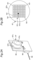
- the temperature sensitive element array 97c is composed of a thermopile (thermoelectric pile), and is configured by an array of temperature sensitive elements 191, 191,... in 8 rows ⁇ 8 columns as shown in Fig. 2B .
- these temperature sensitive elements 191, 191,... can output multiple (64 in this example) temperature signals that represent temperature distribution in the field of view. As will be described later, a temperature represented by a selected signal among these 64 temperature signals is acquired as a first temperature T1.
- the first temperature sensor includes the radiation temperature sensor 97
- the first temperature T1 indicated by the target device 91 can be measured by the radiation temperature sensor 97 at a position in the casing 90M of the control board 90 and away from the target device 91. Therefore, even if the temperature of the target device 91 increases abnormally, the radiation temperature sensor is unlikely to be damaged by temperature increase. Further, the radiation temperature sensor 97 itself has an advantage that there is less risk of a short circuit, ignition, etc. than, for example, a thermocouple temperature sensor.
- the resistance temperature detector 98 is mounted on the sensor substrate 96 together with the radiation temperature sensor 97 described above.
- the resistance temperature detector 98 comes into contact with ambient air at a position where the resistance temperature detector 98 is mounted, and outputs a temperature signal (second temperature T2) that indicates a temperature of the ambient air, due to a resistance change of its resistor caused by a temperature change.
- thermopile array sensor module type manufactured by SSC Co., Ltd.
- the radiation temperature sensor 97 and the resistance temperature detector 98 can be compactly configured.
- the sensor substrate 96 on which the radiation temperature sensor 97 and the resistance temperature detector 98 are mounted, is mounted on the sensor casing 95M described above in a state in which the lens 97a of the radiation temperature sensor 97 faces the outside.
- the sensor casing 95M is firmly attached to an inner surface of the front door 90f of the control board 90 by a mounting bracket (not shown).
- the sensor casing 95M (and the sensor substrate 96) is mounted to the vertical inner surface of the front door 90f in a tilted state so that the target device 91 is in the field of view of the radiation temperature sensor 97.
- a position P2 where the second temperature T2 is measured by the resistance temperature detector 98 is located in the casing 90M of the control board 90 and away from the target device 91. It can be said that the second temperature T2 measured by the resistance temperature detector 98 is substantially equal to temperature indicated by ambient air 93 around the target device 91.
- the radiation temperature sensor 97 and the resistance temperature detector 98 are configured to operate by power supplied from a battery (not shown) mounted on the sensor casing 95M.
- the radiation temperature sensor 97 and the resistance temperature detector 98 may receive power supply from the power supply unit 92 of the control board 90.
- Fig. 3 shows a functional block configuration of the temperature abnormality detection system 1.
- the abnormality determination device 100 included in the temperature abnormality detection system 1 is provided with an operation unit 102, a storage unit 103, a control unit 101, and an alarm unit 105.
- the operation unit 102 includes a keyboard and a mouse in this example.
- the operation unit 102 is particularly used for a user to input a processing start/end instruction and a threshold value Th for determining a temperature abnormality.
- the storage unit 103 includes an EEPROM (Electrically Erasable Programmable Read-Only Memory) capable of storing data non-temporarily and a RAM (Random Access Memory) capable of temporarily storing data.
- Software (computer program) for controlling the control unit 101 is stored in this storage unit 103.
- the storage unit 103 stores the threshold value Th for determining the temperature abnormality input by the user.
- control unit 101 includes a CPU (Central Processing Unit) as a processor that operates according to the control program (software) stored in the storage unit 103.
- This control unit 101 includes a difference calculation unit 141 and a determination unit 142, both of which are configured by the software.
- the difference calculation unit 141 and the determination unit 142 constitute an abnormality determination unit. The operation of this control unit 101 will be described in detail later using an operation flow of Fig. 4 .
- the alarm unit 105 includes a display 151 made of an LCD (Liquid Crystal Display) and a buzzer 152.
- the display 151 displays various information on a display screen based on a signal from the control unit 101.
- the buzzer 152 issues a buzzer sound based on the signal from the control unit 101.
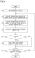
- Fig. 4 shows a flow of temperature abnormality detection processing (a temperature abnormality detection method) executed by the abnormality determination device 100.
- the abnormality determination device 100 receives a processing start instruction via the operation unit 102 shown in Fig. 3 and starts this temperature abnormality detection processing.
- the temperature of the environment where the control board 90 is placed is Ta (see Fig. 3 ).
- a user inputs a threshold value Th for determining a temperature abnormality via the operation unit 102 in this example.
- the threshold value Th 20°C.
- the threshold value Th input by the user is stored in the storage unit 103 shown in Fig. 3 .
- the control unit 101 inputs a temperature signal (first temperature T1) output by the radiation temperature sensor 97 and a temperature signal (second temperature T2) output by the resistance temperature detector 98 via an input/output interface (not shown).
- the temperature signal output by the radiation temperature sensor 97 includes a total of 64 signals by the temperature sensitive elements 191, 191,... in 8 rows ⁇ 8 columns shown in Fig. 2B .
- the control unit 101 selects a signal representing the highest temperature among those signals (that is, temperature of a portion P1 indicating the largest temperature increase on a surface 91a of the target device 91), and acquires the temperature represented by the signal as the first temperature T1.
- a signal representing the highest temperature among those signals that is, temperature of a portion P1 indicating the largest temperature increase on a surface 91a of the target device 91
- output of a certain temperature sensitive element 191x represents the highest temperature.
- the control unit 101 selects a signal output by the temperature sensitive element 191x, and acquires the temperature represented by the signal as the first temperature T1.
- the temperature signal (second temperature T2) output by the resistance temperature detector 98 is the temperature indicated by the ambient air 93 around the target device 91 at the position in the casing 90M of the control board 90 and away from the target device 91.
- step S4 of Fig. 4 the control unit 101 acts as the difference calculation unit 141 and calculates a temperature difference ⁇ T between the first temperature T1 and the second temperature T2.
- ⁇ T T1 - T2. Note that at the start of operation, T1 ⁇ Ta and T2 ⁇ Ta, so ⁇ T ⁇ 0.
- step S5 of Fig. 4 the control unit 101 acts as the determination unit 142 and determines whether or not the temperature difference ⁇ T becomes the threshold value Th or more.
- the control unit 101 determines that the temperature abnormality of the target device 91 has not occurred. Unless a termination condition for terminating this temperature abnormality detection processing is satisfied (NO in step S7), the process returns to step S2 and is repeated.
- step S5 determines that the temperature abnormality of the target device 91 has occurred. Then, the process proceeds to step S6.
- the control unit 101 creates a temperature abnormality signal AT indicating that the temperature abnormality has occurred, and outputs it to the alarm unit 105 shown in Fig. 3 .
- the display 151 included in the alarm unit 105 displays an alarm indicating that a temperature abnormality of the target device 91 has occurred (for example, "a temperature abnormality has occurred in the target device 91") on the display screen.
- the buzzer 152 issues a buzzer sound as an alarm. Therefore, the user can immediately recognize that the temperature abnormality has occurred in the target device 91 installed in the control board 90 by these alarms, and can promptly take necessary measures such as replacing the target device 91.
- the control unit 101 acts as the abnormality determination unit, creates a power cutoff signal PWoff indicating that power supply to the target device 91 is cut off, and outputs it to the power supply unit 92 of the control board 90.
- the power supply unit 92 of the control board 90 automatically and immediately cuts off the power supply to the target device 91. Therefore, it is possible to prevent a fire in the control board 90 from occurring by avoiding a further temperature increase of the target device 91.
- control unit 101 may display, for example, "please cut off power supply to the target device 91" on the display screen of the display 151. Upon seeing this display, the user can manually cut off the power supply to the target device 91.
- step S7 of Fig. 4 the control unit 101 determines whether or not the termination condition for terminating this temperature abnormality detection processing is satisfied.
- the control unit 101 determines that the termination condition is satisfied, and terminates this temperature abnormality detection processing.
- the second temperature T2 is the temperature indicated by the ambient air 93 around the target device 91, it reflects the temperature Ta of the environment where the control board 90 is placed (for example, temperature by season). Therefore, by determining whether or not a temperature abnormality has occurred based on the temperature difference ⁇ T, influence of the temperature Ta of the environment on a determination result is offset. Therefore, according to this temperature abnormality detection system 1, the temperature abnormality of the target device 91 installed in the control board 90 can be accurately detected regardless of the temperature Ta of the environment where the control board 90 is placed.
- the temperature difference ⁇ T between the first temperature T1 and the second temperature T2 at the start of operation in summer and winter is expressed as ⁇ Ts0 and ⁇ Tw0, respectively.
- the temperature differences increase with passage of time from the temperature differences ⁇ Ts0 and ⁇ Tw0 at the start of operation in summer and winter, respectively.
- a certain period of time for example, about 30 minutes to 1 hour
- the temperature differences reach saturation temperature differences ⁇ Ts1 and ⁇ Tw1, with temperature increase amounts ⁇ Tsinc and ⁇ Twinc becoming constant, respectively.
- the threshold value is empirically set to the above-mentioned 20°C so as not to be exceeded by these saturation temperature differences ⁇ Ts1 and ⁇ Tw1. Therefore, when the target device 91 operates normally, the abnormality determination device 100 does not erroneously determine that a temperature abnormality of the target device 91 has occurred.
- the device in the control board 90 when the device in the control board 90 generates abnormal heat (temperature abnormal state), the temperature differences increase with passage of time from the temperature differences at the start of operation ⁇ Ts0 and ⁇ Tw0 in summer and winter, respectively. Heat generation is larger than the temperature increase amounts at normal state ⁇ Tsinc and ⁇ Twinc.
- the temperature abnormality of the target device 91 installed in the control board 90 can be accurately detected regardless of the temperature Ta of the environment where the control board 90 is placed.
- the position P2 where the second temperature T2 is measured by the resistance temperature detector 98 is located in the casing 90M of the control board 90 and away from the target device 91. Therefore, the second temperature T2 becomes the temperature indicated by the ambient air 93 around the target device 91 in the casing of the control board 90, and is less susceptible to a temperature increase of the target device 91. Moreover, since the resistance temperature detector 98 is housed in the sensor casing 95M, it is shielded from infrared rays emitted by the target device 91. Therefore, the second temperature T2 is still less susceptible to the temperature increase of the target device 91.
- the temperature difference ⁇ T between the first temperature T1 and the second temperature T2 is a net temperature increase amount of the target device 91 with respect to the ambient air 93 around the target device 91. As a result, accuracy of determining the temperature abnormality is improved.
- the abnormality determination device 100 acquires the temperature of the portion P1 indicating the largest temperature increase on the surface 91a of the target device 91, that is, the temperature of the portion requiring the most attention, as the first temperature T1.
- the temperature abnormality is determined based on the temperature increase amount of the portion P1 requiring the most attention.
- the above-mentioned temperature abnormality detection method may be recorded as software (computer program) on a recording medium that can store data in a non-transitory manner, such as a compact disc (CD), a digital versatile disc (DVD), or a non-volatile memory.
- a recording medium that can store data in a non-transitory manner, such as a compact disc (CD), a digital versatile disc (DVD), or a non-volatile memory.
- PLC programmable logic controller
- PDA personal digital assistant
- smartphone the temperature abnormality detection method by the above-mentioned abnormality determination device 100 can be executed by these computers.
- the abnormality determination device 100 is installed outside the control board 90, but the present disclosure is not limited to this.
- the abnormality determination device 100 may be incorporated in the sensor casing 95M installed inside the control board 90.
- the abnormality determination device 100 is provided with a communication unit capable of wireless communication, and when a temperature abnormality of the target device 91 occurs, the communication unit transmits an alarm to the outside.
- the communication unit By receiving the alarm, a user can immediately recognize that the temperature abnormality has occurred in the target device 91 installed in the control board 90, and can promptly take necessary measures such as replacing the target device 91.
- the target device 91 is installed in the control board 90, but the present disclosure is not limited to this.
- the target device 91 may be installed in various boards other than the control board 90, such as a switchboard or a distribution board. Even in such a case, the present disclosure is preferably applicable.
- control unit 101 includes the CPU, but the present disclosure is not limited to this.
- the control unit 101 may include a logic circuit (integrated circuit) such as a PLD (Programmable Logic Device) or an FPGA (Field Programmable Gate Array).
Landscapes
- Physics & Mathematics (AREA)
- General Physics & Mathematics (AREA)
- Engineering & Computer Science (AREA)
- Automation & Control Theory (AREA)
- Spectroscopy & Molecular Physics (AREA)
- Human Computer Interaction (AREA)
- Fire-Detection Mechanisms (AREA)
- Measuring Temperature Or Quantity Of Heat (AREA)
- Testing And Monitoring For Control Systems (AREA)
- Control Of Temperature (AREA)
Description
- The present disclosure relates to a temperature abnormality detection system and a temperature abnormality detection method, and more particularly to a temperature abnormality detection system and a temperature abnormality detection method for detecting a temperature abnormality of a target device installed in various boards. The present disclosure also relates to a program for causing a computer to execute such a temperature abnormality detection method.
- Conventionally, for example, as this kind of temperature abnormality detection system, an elevator control device disclosed in Patent Document 1 (
JP 2009-067521 A -
EP 0 857 012 A1 -
US 6 921 895 B1 discloses a sensor module comprising a radiation sensor, a temperature sensor and a circuit computing the difference between both sensors' output, to compensate temperature and provide object temperature dependent output. -
US 7 362 224 B2 discloses a thermal door sensor with least two thermally sensitive sensors provided in an array arrangement. - Patent Document 1:
JP 2009-067521 A - By the way, as shown in
Fig. 6A , when the device in the control board operates normally, temperatures increase with passage of time from operation start temperatures Ts0 and Tw0 in summer and winter, respectively (here, Ts0 > Tw0 as temperatures by seasons). When a certain period of time (for example, about 30 minutes to 1 hour) passes, the temperatures reach saturation temperatures Ts1 and Tw1, with temperature increase amounts ΔTsinc and ΔTwinc becoming constant, respectively. Therefore, in technique of above conventional example, a first threshold value (temperature upper limit value) Tul is set to a temperature slightly exceeding the saturation temperature Ts1 in summer (for example, 80°C) so as not to make false determinations in summer. Here, as shown inFig. 6B , when the device in the control board generates abnormal heat (temperature abnormal state), the temperatures increase with passage of time from the operation start temperatures Ts0 and Tw0 in summer and winter, with larger heat generation than the temperature increase amounts at normal state ΔTsinc and ΔTwinc, respectively (Temperature increase amounts at the temperature abnormal state are represented by ΔTsinc' and ΔTwinc'. Here, ΔTsinc < Tsinc' and ΔTwinc < ΔTwinc'.). The temperatures reach higher temperatures Ts1' and Tw1' than those in the normal state, respectively. In the technique of the conventional example, when the temperature is abnormal in summer, the temperature Ts1' exceeds the temperature upper limit value Tul, so that the abnormality can be detected. However, when the temperature is abnormal in winter, a situation occurs in which the temperature Tw1' does not exceed the temperature upper limit value Tul, and there arises a problem that the abnormality cannot be detected. - Therefore, an object of the present disclosure is to provide a temperature abnormality detection system and a temperature abnormality detection method that can accurately detect a temperature abnormality of a target device installed in a board, regardless of the temperature of environment where the board is placed (for example, temperature by season). Further, an object of the present disclosure is to provide a program for causing a computer to execute such a temperature abnormality detection method.
- In order to achieve the above object, a temperature abnormality detection system according to the present invention is provided according to
claim 1. - In the present specification, the "target device" refers to a device that is a target of temperature measurement and may have a temperature increase during operation. Further, the "board" includes various boards such as a switchboard, a control board, and a distribution board.
- In the temperature abnormality detection system of the present disclosure, the first temperature sensor measures the first temperature indicated by the target device installed in the board. The second temperature sensor measures the second temperature indicated by the ambient air around the target device. The abnormality determination unit calculates the temperature difference between the first temperature and the second temperature, and determines that the temperature abnormality of the target device has occurred when the temperature difference becomes the predetermined threshold value or more. Here, since the second temperature is the temperature indicated by the ambient air around the target device, it reflects the temperature of environment where the board is placed (for example, temperature by season). Therefore, by determining whether or not the temperature abnormality has occurred based on the temperature difference between the first temperature and the second temperature, influence of the temperature of the environment on a determination result is offset. Therefore, according to the temperature abnormality detection system of the present disclosure, it is possible to accurately detect the temperature abnormality of the target device installed in the board regardless of the temperature of the environment where the board is placed.
- In the temperature abnormality detection system according to the invention, a position where the second temperature is measured is a position inside a casing of the board.
- In the temperature abnormality detection system of this one example, the second temperature is a temperature indicated by the ambient air around the target device in the casing of the board. Therefore, the temperature difference between the first temperature and the second temperature is a net temperature increase amount of the target device with respect to the ambient air around the target device. In response to this, when the temperature difference between the first temperature and the second temperature, that is, the net temperature increase amount of the target device becomes the predetermined threshold value or more, the abnormality determination unit determines that the temperature abnormality of the target device has occurred. Therefore, accuracy of determining the temperature abnormality is improved.
- In the temperature abnormality detection system according to the invention, the position where the second temperature is measured is a position away from the target device.
- In the temperature abnormality detection system of the invention, the second temperature is a temperature at the position in the casing of the board and away from the target device. Therefore, the second temperature is less likely to be affected by the temperature increase of the target device. Therefore, the accuracy of determining the temperature abnormality is further improved.
- In the temperature abnormality detection system of one example, the first temperature sensor acquires, as the first temperature, a temperature of a portion indicating a largest temperature increase on a surface of the target device.
- In the temperature abnormality detection system of this one example, the first temperature sensor acquires, as the first temperature, the temperature of the portion indicating the largest temperature increase on the surface of the target device. Therefore, the temperature difference between the first temperature and the second temperature is a temperature increase amount of the portion requiring the most attention on the surface of the target device with respect to the ambient air around the target device. In response to this, when the temperature difference between the first temperature and the second temperature, that is, the temperature increase amount of the portion requiring the most attention on the surface of the target device becomes the predetermined threshold value or more, the abnormality determination unit determines that the temperature abnormality of the target device has occurred. As a result, when the temperature increase varies on the surface of the target device, the temperature abnormality is determined based on the temperature increase amount of the portion requiring the most attention. With this configuration, it is possible to effectively prevent occurrence of a fire in the board.
- In the temperature abnormality detection system according to the invention, the first temperature sensor includes a radiation temperature sensor installed in a casing of the board.
- In the present specification, the "radiation temperature sensor" refers to a type of temperature sensor that measures temperature by detecting infrared radiation emitted by the target device.
- In the temperature abnormality detection system of the invention, the radiation temperature sensor included in the first temperature sensor can measure the first temperature indicated by the target device at a position in the casing of the board and away from the target device. Therefore, even if the temperature of the target device increases abnormally, it is unlikely to be damaged by the temperature increase. Further, the radiation temperature sensor itself has an advantage that there is less risk of a short circuit, ignition, etc. than, for example, a thermocouple temperature sensor.
- In the temperature abnormality detection system according to the invention,
- the radiation temperature sensor is mounted on a sensor casing installed in the casing of the board, and
- the second temperature sensor includes a contact type temperature sensor housed in the sensor casing.
- In the present specification, the "contact type temperature sensor", such as a resistance temperature detector, a thermistor, a thermocouple, and an IC (Integrated Circuit) temperature sensor, means a type of temperature sensor that measures a temperature of an object (here, ambient air) to be measured by the temperature sensor coming into contact with the object.
- In the temperature abnormality detection system of this one example, since the contact type temperature sensor included in the second temperature sensor is housed in the sensor casing, it is shielded from infrared rays emitted by the target device. Therefore, the second temperature is still less affected by the temperature increase of the target device, and the accuracy of determining the temperature abnormality is further improved. Since the radiation temperature sensor is mounted on the sensor casing installed in the casing of the board, it can be firmly attached to an inner wall of the casing of the board, for example, via the sensor casing. Further, as the radiation temperature sensor and the contact type temperature sensor, for example, a commercially available product of a type mounted on a common sensor substrate can be used. Therefore, the first temperature sensor and the second temperature sensor can be compactly configured.
- The temperature abnormality detection system of one example further comprises an alarm unit that issues an alarm when it is determined that the temperature abnormality has occurred.
- In the temperature abnormality detection system of this one example, when it is determined that the temperature abnormality has occurred, the alarm unit issues an alarm. Therefore, a user can immediately recognize that the temperature abnormality has occurred in the target device installed in the board by this alarm, and can quickly take necessary measures such as replacing the target device.
- In the temperature abnormality detection system of one example, when it is determined that the temperature abnormality has occurred, the abnormality determination unit outputs a power cutoff signal for cutting off power supply to the target device.
- In the temperature abnormality detection system of this one example, when it is determined that the temperature abnormality has occurred, the abnormality determination unit outputs the power cutoff signal for cutting off the power supply to the target device. Therefore, by cutting off the power supply to the target device in response to this power cutoff signal, it is possible to avoid a further temperature increase of the target device and prevent occurrence of a fire in the board.
- In another aspect, a temperature abnormality detection method according to the present disclosure is provided as defined in claim 8.
- According to the temperature abnormality detection method of the present disclosure, it is possible to accurately detect the temperature abnormality of the target device installed in the board regardless of temperature of environment where the board is placed.
- In yet another aspect, a program according to claim 9 is provided.
- By causing a computer to execute the program of the present disclosure, the temperature abnormality detection method can be implemented.
- As is clear from the above, according to the temperature abnormality detection system and the temperature abnormality detection method of the present disclosure, the temperature abnormality of the target device installed in the board can be accurately detected regardless of the temperature of the environment where the board is placed. Further, the temperature abnormality detection method can be implemented by causing the computer to execute the program of the present disclosure.
-
-
Fig. 1A is a diagram showing a schematic configuration of a temperature abnormality detection system according to an example of the present disclosure.Fig. 1B is a diagram schematically showing arrangement of a target device to be a target of temperature abnormality detection and a sensor casing, which are provided in a control board inFig. 1A with a front door of the control board closed. -
Fig. 2A is a diagram showing appearance of a sensor array module mounted on the sensor casing.Fig. 2B is a diagram showing a temperature sensitive element array of a radiation temperature sensor forming a first temperature sensor included in the sensor array module. -
Fig. 3 is a diagram showing a functional block configuration of the temperature abnormality detection system. -
Fig. 4 is a flowchart showing an operation flow of temperature abnormality detection executed by the temperature abnormality detection system. -
Fig. 5A and Fig. 5B are graphs for explaining an effect of the temperature abnormality detection system. -
Fig. 6A and Fig. 6B are graphs for explaining a problem according to a conventional example. - Hereinafter, an example of the present disclosure will be described in detail with reference to the drawings.
-
Fig. 1A schematically shows a schematic configuration of a temperatureabnormality detection system 1 according to an example of the present disclosure. In this example, the temperatureabnormality detection system 1 detects a temperature abnormality of atarget device 91 installed in acontrol board 90 as an example of a board, and roughly includes asensor device 95 installed inside of afront door 90f of thecontrol board 90 and anabnormality determination device 100 installed outside thecontrol board 90. In this example, thesensor device 95 in thecontrol board 90 and theabnormality determination device 100 are communicably connected viasignal cables sensor device 95 and theabnormality determination device 100 may be able to communicate with each other via wireless communication. - The
control board 90 has a general configuration. In this example, it includes acasing 90M having a rectangular parallelepiped outer shape, thetarget device 91 installed in thiscasing 90M, and a power supply unit 92 (seeFig. 3 described later) that supplies power to thistarget device 91. In this example, thecasing 90M has thefront door 90f that can be opened and closed as shown by an arrow E inFig. 1A . As shown inFig. 1B (schematically showing the inside of thecontrol board 90 viewed from a right side with thefront door 90f closed), thetarget device 91 is attached along an inner surface of arear wall 90r of thecasing 90M. - In addition to various devices such as a DC power supply, a contactor, a controller, a motor driver, and a breaker, examples of the
target device 91 include those having a possibility of a temperature increase during operation, such as a power semiconductor, a relay, a heat sink, power system wiring, a terminal, etc. that form a part of the devices. - The
sensor device 95 includes asensor casing 95M having a flat rectangular parallelepiped outer shape, aradiation temperature sensor 97 forming a first temperature sensor mounted on thesensor casing 95M, and aresistance temperature detector 98 as an example of a contact type temperature sensor and forming a second temperature sensor housed in thesensor casing 95M. Note that the second temperature sensor may be a contact type temperature sensor of another type, such as a thermistor, a thermocouple, or an IC temperature sensor, instead of theresistance temperature detector 98. - As shown in
Fig. 2A , in this example, theradiation temperature sensor 97 includes acylindrical can case 97b mounted on asensor substrate 96, alens 97a attached so as to close a tip opening of thiscan case 97b, and a temperaturesensitive element array 97c arranged along thesensor substrate 96 in thecan case 97b. Thelens 97a collects infrared rays emitted by thetarget device 91 and makes them incident on the temperaturesensitive element array 97c. In this example, the temperaturesensitive element array 97c is composed of a thermopile (thermoelectric pile), and is configured by an array of temperaturesensitive elements Fig. 2B . By looking through thelens 97a in different directions in a field of view of theradiation temperature sensor 97, these temperaturesensitive elements - In this way, when the first temperature sensor includes the
radiation temperature sensor 97, the first temperature T1 indicated by thetarget device 91 can be measured by theradiation temperature sensor 97 at a position in thecasing 90M of thecontrol board 90 and away from thetarget device 91. Therefore, even if the temperature of thetarget device 91 increases abnormally, the radiation temperature sensor is unlikely to be damaged by temperature increase. Further, theradiation temperature sensor 97 itself has an advantage that there is less risk of a short circuit, ignition, etc. than, for example, a thermocouple temperature sensor. - As shown in
Fig. 2A , theresistance temperature detector 98 is mounted on thesensor substrate 96 together with theradiation temperature sensor 97 described above. Theresistance temperature detector 98 comes into contact with ambient air at a position where theresistance temperature detector 98 is mounted, and outputs a temperature signal (second temperature T2) that indicates a temperature of the ambient air, due to a resistance change of its resistor caused by a temperature change. - As the
sensor substrate 96 in which theradiation temperature sensor 97 and theresistance temperature detector 98 are mounted in common in this way, a commercially available product, for example, a thermopile array sensor (module type) manufactured by SSC Co., Ltd. can be used. As a result, theradiation temperature sensor 97 and theresistance temperature detector 98 can be compactly configured. - As shown in
Fig. 1B , thesensor substrate 96, on which theradiation temperature sensor 97 and theresistance temperature detector 98 are mounted, is mounted on thesensor casing 95M described above in a state in which thelens 97a of theradiation temperature sensor 97 faces the outside. Thesensor casing 95M is firmly attached to an inner surface of thefront door 90f of thecontrol board 90 by a mounting bracket (not shown). In this example, thesensor casing 95M (and the sensor substrate 96) is mounted to the vertical inner surface of thefront door 90f in a tilted state so that thetarget device 91 is in the field of view of theradiation temperature sensor 97. - As a result, a position P2 where the second temperature T2 is measured by the
resistance temperature detector 98 is located in thecasing 90M of thecontrol board 90 and away from thetarget device 91. It can be said that the second temperature T2 measured by theresistance temperature detector 98 is substantially equal to temperature indicated byambient air 93 around thetarget device 91. - Note that, in this example, the
radiation temperature sensor 97 and theresistance temperature detector 98 are configured to operate by power supplied from a battery (not shown) mounted on thesensor casing 95M. However, theradiation temperature sensor 97 and theresistance temperature detector 98 may receive power supply from thepower supply unit 92 of thecontrol board 90. -
Fig. 3 shows a functional block configuration of the temperatureabnormality detection system 1. - In this example, the
abnormality determination device 100 included in the temperatureabnormality detection system 1 is provided with anoperation unit 102, astorage unit 103, acontrol unit 101, and analarm unit 105. - The
operation unit 102 includes a keyboard and a mouse in this example. In this example, theoperation unit 102 is particularly used for a user to input a processing start/end instruction and a threshold value Th for determining a temperature abnormality. - In this example, the
storage unit 103 includes an EEPROM (Electrically Erasable Programmable Read-Only Memory) capable of storing data non-temporarily and a RAM (Random Access Memory) capable of temporarily storing data. Software (computer program) for controlling thecontrol unit 101 is stored in thisstorage unit 103. Further, in this example, thestorage unit 103 stores the threshold value Th for determining the temperature abnormality input by the user. - In this example, the
control unit 101 includes a CPU (Central Processing Unit) as a processor that operates according to the control program (software) stored in thestorage unit 103. Thiscontrol unit 101 includes adifference calculation unit 141 and adetermination unit 142, both of which are configured by the software. Thedifference calculation unit 141 and thedetermination unit 142 constitute an abnormality determination unit. The operation of thiscontrol unit 101 will be described in detail later using an operation flow ofFig. 4 . - In this example, the
alarm unit 105 includes adisplay 151 made of an LCD (Liquid Crystal Display) and abuzzer 152. Thedisplay 151 displays various information on a display screen based on a signal from thecontrol unit 101. Thebuzzer 152 issues a buzzer sound based on the signal from thecontrol unit 101. -
Fig. 4 shows a flow of temperature abnormality detection processing (a temperature abnormality detection method) executed by theabnormality determination device 100. In this example, at the same time as operation of thecontrol board 90 is started, theabnormality determination device 100 receives a processing start instruction via theoperation unit 102 shown inFig. 3 and starts this temperature abnormality detection processing. The temperature of the environment where thecontrol board 90 is placed is Ta (seeFig. 3 ). - First, as shown in step S1 of
Fig. 4 , a user inputs a threshold value Th for determining a temperature abnormality via theoperation unit 102 in this example. In this example, the threshold value Th = 20°C. The threshold value Th input by the user is stored in thestorage unit 103 shown inFig. 3 . - Next, as shown in steps S2 and S3 of
Fig. 4 , thecontrol unit 101 inputs a temperature signal (first temperature T1) output by theradiation temperature sensor 97 and a temperature signal (second temperature T2) output by theresistance temperature detector 98 via an input/output interface (not shown). - In this example, the temperature signal output by the
radiation temperature sensor 97 includes a total of 64 signals by the temperaturesensitive elements Fig. 2B . Thecontrol unit 101 selects a signal representing the highest temperature among those signals (that is, temperature of a portion P1 indicating the largest temperature increase on asurface 91a of the target device 91), and acquires the temperature represented by the signal as the first temperature T1. This is because the portion P1 indicating the largest temperature increase on thesurface 91a of thetarget device 91 is a portion that requires the most attention. Specifically, for example, it is assumed that among the temperaturesensitive elements Fig. 2B , output of a certain temperaturesensitive element 191x represents the highest temperature. In that case, thecontrol unit 101 selects a signal output by the temperaturesensitive element 191x, and acquires the temperature represented by the signal as the first temperature T1. - As described with reference to
Fig. 1B , the temperature signal (second temperature T2) output by theresistance temperature detector 98 is the temperature indicated by theambient air 93 around thetarget device 91 at the position in thecasing 90M of thecontrol board 90 and away from thetarget device 91. - Next, as shown in step S4 of
Fig. 4 , thecontrol unit 101 acts as thedifference calculation unit 141 and calculates a temperature difference ΔT between the first temperature T1 and the second temperature T2. Here, ΔT = T1 - T2. Note that at the start of operation, T1 ≈ Ta and T2 ≈ Ta, so ΔT ≈ 0. - Next, as shown in step S5 of
Fig. 4 , thecontrol unit 101 acts as thedetermination unit 142 and determines whether or not the temperature difference ΔT becomes the threshold value Th or more. Here, if the temperature difference ΔT is less than the threshold value Th (NO in step S5), the control unit 101 (determination unit 142) determines that the temperature abnormality of thetarget device 91 has not occurred. Unless a termination condition for terminating this temperature abnormality detection processing is satisfied (NO in step S7), the process returns to step S2 and is repeated. - On the other hand, if the temperature difference ΔT becomes the threshold value Th or more (YES in step S5), the control unit 101 (determination unit 142) determines that the temperature abnormality of the
target device 91 has occurred. Then, the process proceeds to step S6. When determining that this temperature abnormality has occurred, thecontrol unit 101 creates a temperature abnormality signal AT indicating that the temperature abnormality has occurred, and outputs it to thealarm unit 105 shown inFig. 3 . As a result, thedisplay 151 included in thealarm unit 105 displays an alarm indicating that a temperature abnormality of thetarget device 91 has occurred (for example, "a temperature abnormality has occurred in thetarget device 91") on the display screen. In addition, thebuzzer 152 issues a buzzer sound as an alarm. Therefore, the user can immediately recognize that the temperature abnormality has occurred in thetarget device 91 installed in thecontrol board 90 by these alarms, and can promptly take necessary measures such as replacing thetarget device 91. - Further, when determining that the above temperature abnormality has occurred, the
control unit 101 acts as the abnormality determination unit, creates a power cutoff signal PWoff indicating that power supply to thetarget device 91 is cut off, and outputs it to thepower supply unit 92 of thecontrol board 90. In this example, when receiving the power cutoff signal PWoff, thepower supply unit 92 of thecontrol board 90 automatically and immediately cuts off the power supply to thetarget device 91. Therefore, it is possible to prevent a fire in thecontrol board 90 from occurring by avoiding a further temperature increase of thetarget device 91. - Note that, instead of automatically and immediately cutting off the power supply to the
target device 91, thecontrol unit 101 may display, for example, "please cut off power supply to thetarget device 91" on the display screen of thedisplay 151. Upon seeing this display, the user can manually cut off the power supply to thetarget device 91. - After that, in step S7 of
Fig. 4 , thecontrol unit 101 determines whether or not the termination condition for terminating this temperature abnormality detection processing is satisfied. In this example, when a predetermined processing period elapses from the start of this temperature abnormality detection processing or when a processing end instruction is received via theoperation unit 102, thecontrol unit 101 determines that the termination condition is satisfied, and terminates this temperature abnormality detection processing. - As described above, this temperature
abnormality detection system 1 detects a temperature abnormality of thetarget device 91 based on whether or not the temperature difference ΔT (= T1 - T2) between the first temperature T1 and the second temperature T2 becomes the threshold value Th or more. Here, since the second temperature T2 is the temperature indicated by theambient air 93 around thetarget device 91, it reflects the temperature Ta of the environment where thecontrol board 90 is placed (for example, temperature by season). Therefore, by determining whether or not a temperature abnormality has occurred based on the temperature difference ΔT, influence of the temperature Ta of the environment on a determination result is offset. Therefore, according to this temperatureabnormality detection system 1, the temperature abnormality of thetarget device 91 installed in thecontrol board 90 can be accurately detected regardless of the temperature Ta of the environment where thecontrol board 90 is placed. - For example, the temperature difference ΔT between the first temperature T1 and the second temperature T2 at the start of operation in summer and winter is expressed as ΔTs0 and ΔTw0, respectively. At the start of operation, ΔTs0 ≈ 0 and ΔTw0 ≈ 0. As shown in
Fig. 5A , when thetarget device 91 in thecontrol board 90 operates normally, the temperature differences increase with passage of time from the temperature differences ΔTs0 and ΔTw0 at the start of operation in summer and winter, respectively. When a certain period of time (for example, about 30 minutes to 1 hour) passes, the temperature differences reach saturation temperature differences ΔTs1 and ΔTw1, with temperature increase amounts ΔTsinc and ΔTwinc becoming constant, respectively. In this example, the threshold value is empirically set to the above-mentioned 20°C so as not to be exceeded by these saturation temperature differences ΔTs1 and ΔTw1. Therefore, when thetarget device 91 operates normally, theabnormality determination device 100 does not erroneously determine that a temperature abnormality of thetarget device 91 has occurred. In addition, as shown inFig. 5B , when the device in thecontrol board 90 generates abnormal heat (temperature abnormal state), the temperature differences increase with passage of time from the temperature differences at the start of operation ΔTs0 and ΔTw0 in summer and winter, respectively. Heat generation is larger than the temperature increase amounts at normal state ΔTsinc and ΔTwinc. (Temperature increase amounts at the temperature abnormal state are represented by ΔTsinc' and ΔTwinc'. Here, ΔTsinc < Tsinc' and ΔTwinc < ΔTwinc'.) The temperature differences reach ΔTs1' and ΔTw1', respectively, higher than those in the normal state. As a result, ΔTs1' > Th and ΔTw1' > Th. Therefore, theabnormality determination device 100 can accurately detect the temperature abnormality of thetarget device 91 in both the summer and the winter. - As described above, according to the temperature
abnormality detection system 1, the temperature abnormality of thetarget device 91 installed in thecontrol board 90 can be accurately detected regardless of the temperature Ta of the environment where thecontrol board 90 is placed. - In particular, in the above example, the position P2 where the second temperature T2 is measured by the
resistance temperature detector 98 is located in thecasing 90M of thecontrol board 90 and away from thetarget device 91. Therefore, the second temperature T2 becomes the temperature indicated by theambient air 93 around thetarget device 91 in the casing of thecontrol board 90, and is less susceptible to a temperature increase of thetarget device 91. Moreover, since theresistance temperature detector 98 is housed in thesensor casing 95M, it is shielded from infrared rays emitted by thetarget device 91. Therefore, the second temperature T2 is still less susceptible to the temperature increase of thetarget device 91. Therefore, the temperature difference ΔT between the first temperature T1 and the second temperature T2 is a net temperature increase amount of thetarget device 91 with respect to theambient air 93 around thetarget device 91. As a result, accuracy of determining the temperature abnormality is improved. - Further, in the above example, the
abnormality determination device 100 acquires the temperature of the portion P1 indicating the largest temperature increase on thesurface 91a of thetarget device 91, that is, the temperature of the portion requiring the most attention, as the first temperature T1. As a result, when the temperature increase varies on thesurface 91a of thetarget device 91, the temperature abnormality is determined based on the temperature increase amount of the portion P1 requiring the most attention. With this configuration, it is possible to effectively prevent occurrence of a fire in thecontrol board 90. - The above-mentioned temperature abnormality detection method may be recorded as software (computer program) on a recording medium that can store data in a non-transitory manner, such as a compact disc (CD), a digital versatile disc (DVD), or a non-volatile memory. By installing the software recorded on such a recording medium on practical computer devices such as a programmable logic controller (PLC), a personal computer, a personal digital assistant (PDA), and a smartphone, the temperature abnormality detection method by the above-mentioned
abnormality determination device 100 can be executed by these computers. - Further, in the above example, the
abnormality determination device 100 is installed outside thecontrol board 90, but the present disclosure is not limited to this. For example, theabnormality determination device 100 may be incorporated in thesensor casing 95M installed inside thecontrol board 90. In that case, it is desirable that theabnormality determination device 100 is provided with a communication unit capable of wireless communication, and when a temperature abnormality of thetarget device 91 occurs, the communication unit transmits an alarm to the outside. By receiving the alarm, a user can immediately recognize that the temperature abnormality has occurred in thetarget device 91 installed in thecontrol board 90, and can promptly take necessary measures such as replacing thetarget device 91. - Further, in the above example, it is assumed that the
target device 91 is installed in thecontrol board 90, but the present disclosure is not limited to this. Thetarget device 91 may be installed in various boards other than thecontrol board 90, such as a switchboard or a distribution board. Even in such a case, the present disclosure is preferably applicable. - Further, in the above-described example, the
control unit 101 includes the CPU, but the present disclosure is not limited to this. Thecontrol unit 101 may include a logic circuit (integrated circuit) such as a PLD (Programmable Logic Device) or an FPGA (Field Programmable Gate Array). -
- 1
- Temperature abnormality detection system
- 90
- Control board
- 91
- Target device
- 97
- Radiation temperature sensor
- 98
- Resistance temperature detector
- 100
- Abnormality determination device
- 101
- Control unit
- 105
- Alarm unit
Claims (9)
- A temperature abnormality detection system (1) configured to detect a temperature abnormality of a target device (91) installed in a board casing (90M) of a board (90),
wherein the temperature abnormality detection system (1) comprises:a sensor casing (95M);a first temperature sensor that includes a radiation temperature sensor (97) and configured to measure a first temperature (T1) indicated by the target device (91) by the radiation temperature sensor (97) at a position apart from the target device (91);a second temperature sensor that includes a contact type temperature sensor (98) and configured to measure a second temperature (T2) indicated by ambient air around the target device (91) by the contact type temperature sensor (98) inside the board casing (90M); anda substrate (96) mounted on the sensor casing,wherein the first temperature sensor and the second temperature sensor are mounted in common on the substrate in the sensor casing,the temperature abnormality detection system further comprising a processor (101) configured to act as an abnormality determination unit to calculate a temperature difference (ΔT) between the first temperature (T1) and the second temperature (T2),characterized in thatthe processor is further configured to determine that a temperature abnormality of the target device (91) has occurred when the temperature difference (ΔT) becomes a predetermined threshold value (Th) or more, andthe sensor casing (95M) is configured to be installed in the casing of the board in a tilted state so that the target device (91) is in a field of view of the radiation temperature sensor (97). - The temperature abnormality detection system (1) according to claim 1, wherein the sensor casing (95M) shields the contact type temperature sensor (98) from infrared ray emitted by the target device (91) so that a lens of the radiation temperature sensor (97) faces an outside of the sensor casing (95M); and
the sensor casing (95M) is configured to be installed in the casing of the board by a mounting bracket. - The temperature abnormality detection system (1) according to claim 2, wherein,
in the sensor casing (95M), a battery is mounted for supplying power to the radiation temperature sensor (97) and the contact type temperature sensor (98). - The temperature abnormality detection system (1) according to any one of claims 1 to 3, whereinthe radiation temperature sensor (97) of the first temperature sensor incudes a plurality of temperature sensitive elements (191) arranged in a matrix, andthe processor (101) is configured to acquire, as the first temperature (T1), a temperature of a portion (P1) indicating a largest temperature increase on a surface (91a) of the target device (91) by selecting a signal indicating a highest temperature among temperature signals output by the plurality of temperature sensitive elements (191).
- The temperature abnormality detection system (1) according to any one of claims 1 to 4, wherein
the processor (101) is installed outside the board casing (90M) and is communicably connected with the first temperature sensor and the second temperature sensor via a signal cable (99, 180) or wireless communication. - The temperature abnormality detection system (1) according to any one of claims 1 to 5, further comprising
an alarm unit (105) that issues an alarm when it is determined that the temperature abnormality has occurred. - The temperature abnormality detection system (1) according to any one of claims 1 to 6, wherein
when it is determined that the temperature abnormality has occurred, the processor (101) as the abnormality determination unit outputs a power cutoff signal (PWoff) for cutting off power supply to the target device (91). - A temperature abnormality detection method performed by the temperature abnormality detection system (1) according to claim 1, for detecting the temperature abnormality of the target device (91) installed in the board casing (90M); characterized in that:
the temperature abnormality detection method comprises:installing the abnormality detection system in the casing of the board in a tilted state so that the target device is in a field of view of the radiation temperature sensor;measuring the first temperature (T1) indicated by the target device (91) by the radiation temperature sensor (97) of the first temperature sensor, and measuring the second temperature (T2) indicated by ambient air around the target device (91) by the contact type temperature sensor (98) of the second temperature sensor; andcalculating, by the processor (101) as the abnormality determination unit, the temperature difference (ΔT) between the first temperature (T1) and the second temperature (T2), and determining that the temperature abnormality of the target device (91) has occurred when the temperature difference (ΔT) becomes the threshold value (Th) or more. - A program for causing a computer to execute the temperature abnormality detection method according to claim 8.
Applications Claiming Priority (2)
| Application Number | Priority Date | Filing Date | Title |
|---|---|---|---|
| JP2018205484A JP7103164B2 (en) | 2018-10-31 | 2018-10-31 | Temperature anomaly detection system, temperature anomaly detection method, and program |
| PCT/JP2019/036450 WO2020090261A1 (en) | 2018-10-31 | 2019-09-18 | Temperature abnormality detection system, temperature abnormality detection method, and program |
Publications (3)
| Publication Number | Publication Date |
|---|---|
| EP3845987A1 EP3845987A1 (en) | 2021-07-07 |
| EP3845987A4 EP3845987A4 (en) | 2022-05-18 |
| EP3845987B1 true EP3845987B1 (en) | 2024-04-10 |
Family
ID=70463041
Family Applications (1)
| Application Number | Title | Priority Date | Filing Date |
|---|---|---|---|
| EP19877922.5A Active EP3845987B1 (en) | 2018-10-31 | 2019-09-18 | Temperature abnormality detection system, temperature abnormality detection method, and program |
Country Status (5)
| Country | Link |
|---|---|
| US (1) | US11867569B2 (en) |
| EP (1) | EP3845987B1 (en) |
| JP (1) | JP7103164B2 (en) |
| CN (1) | CN112740130B (en) |
| WO (1) | WO2020090261A1 (en) |
Families Citing this family (3)
| Publication number | Priority date | Publication date | Assignee | Title |
|---|---|---|---|---|
| US12353199B2 (en) * | 2020-01-17 | 2025-07-08 | Nippon Telegraph And Telephone Corporation | Communication apparatus and temperature monitoring method |
| JP7505919B2 (en) * | 2020-05-29 | 2024-06-25 | 日鉄テックスエンジ株式会社 | Factory equipment monitoring system, factory equipment monitoring method and program |
| CN116304956B (en) * | 2023-05-15 | 2023-08-15 | 济宁市质量计量检验检测研究院(济宁半导体及显示产品质量监督检验中心、济宁市纤维质量监测中心) | Chip temperature anomaly online detection method |
Citations (2)
| Publication number | Priority date | Publication date | Assignee | Title |
|---|---|---|---|---|
| US6921895B1 (en) * | 1999-02-23 | 2005-07-26 | Perkinelmer Optoelectronics Gmbh | Sensor module with integrated signal processing |
| US7362224B2 (en) * | 2004-07-22 | 2008-04-22 | B.E.A. S.A. | Thermally sensitive array device for presence detection around automatic doors |
Family Cites Families (18)
| Publication number | Priority date | Publication date | Assignee | Title |
|---|---|---|---|---|
| JPS62211997A (en) * | 1986-03-12 | 1987-09-17 | 日本電気株式会社 | Monitor for abnormality in cooling of electronic equipment |
| JPH07218568A (en) * | 1994-01-28 | 1995-08-18 | Toshiba Corp | Electric equipment temperature monitoring method |
| US6039471A (en) * | 1996-05-22 | 2000-03-21 | Integrated Device Technology, Inc. | Device for simulating dissipation of thermal power by a board supporting an electronic component |
| JP3011117B2 (en) * | 1997-01-31 | 2000-02-21 | 日本電気株式会社 | Cooling alarm detection system |
| JP3811072B2 (en) * | 2002-01-18 | 2006-08-16 | 本田技研工業株式会社 | Abnormality detection device for mobile robot |
| JP3451554B1 (en) * | 2002-06-12 | 2003-09-29 | オムロン株式会社 | Error detection method, error detection device and temperature controller |
| JP5200465B2 (en) | 2007-09-12 | 2013-06-05 | 三菱電機株式会社 | Elevator control device |
| CA2853033C (en) * | 2011-10-21 | 2019-07-16 | Nest Labs, Inc. | User-friendly, network connected learning thermostat and related systems and methods |
| JP5770649B2 (en) * | 2012-01-27 | 2015-08-26 | 日野自動車株式会社 | Abnormality detection apparatus, hybrid vehicle, abnormality detection method, and program |
| JP5584253B2 (en) | 2012-05-07 | 2014-09-03 | 東芝三菱電機産業システム株式会社 | Remote monitoring device |
| WO2015155706A1 (en) * | 2014-04-09 | 2015-10-15 | Maurizio Tropea | Apparatus for air-conditioning of environments in the marine field |
| CN104571086B (en) * | 2014-12-24 | 2018-06-29 | 上海理工大学 | Temperature controller emulation test method based on transmission function |
| GB2533936B (en) | 2015-01-07 | 2017-10-25 | Homeserve Plc | Flow detection device |
| JP2016130699A (en) | 2015-01-14 | 2016-07-21 | アズビル株式会社 | Thermopile array sensor and autopile processing method for thermopile array sensor |
| US10017894B2 (en) * | 2015-08-10 | 2018-07-10 | David A. Strahle | Clean status indicator |
| CN105627508B (en) * | 2015-12-30 | 2018-08-14 | 美的集团武汉制冷设备有限公司 | Air conditioning control method based on shell temperature and device |
| TWI818208B (en) * | 2020-11-20 | 2023-10-11 | 神雲科技股份有限公司 | Temperature correction method and server |
| US20230099638A1 (en) * | 2021-09-24 | 2023-03-30 | Apple Inc. | System and method for temperature sensing using thermopile integrated with rigid printed circuit board |
-
2018
- 2018-10-31 JP JP2018205484A patent/JP7103164B2/en active Active
-
2019
- 2019-09-18 WO PCT/JP2019/036450 patent/WO2020090261A1/en not_active Ceased
- 2019-09-18 EP EP19877922.5A patent/EP3845987B1/en active Active
- 2019-09-18 CN CN201980061162.7A patent/CN112740130B/en active Active
-
2021
- 2021-03-31 US US17/218,883 patent/US11867569B2/en active Active
Patent Citations (2)
| Publication number | Priority date | Publication date | Assignee | Title |
|---|---|---|---|---|
| US6921895B1 (en) * | 1999-02-23 | 2005-07-26 | Perkinelmer Optoelectronics Gmbh | Sensor module with integrated signal processing |
| US7362224B2 (en) * | 2004-07-22 | 2008-04-22 | B.E.A. S.A. | Thermally sensitive array device for presence detection around automatic doors |
Also Published As
| Publication number | Publication date |
|---|---|
| WO2020090261A1 (en) | 2020-05-07 |
| CN112740130A (en) | 2021-04-30 |
| US20210215546A1 (en) | 2021-07-15 |
| EP3845987A4 (en) | 2022-05-18 |
| US11867569B2 (en) | 2024-01-09 |
| EP3845987A1 (en) | 2021-07-07 |
| CN112740130B (en) | 2024-07-05 |
| JP7103164B2 (en) | 2022-07-20 |
| JP2020071684A (en) | 2020-05-07 |
Similar Documents
| Publication | Publication Date | Title |
|---|---|---|
| US11867569B2 (en) | Temperature abnormality detection system, temperature abnormality detection method, and computer-readable recording medium | |
| US12298190B2 (en) | Temperature threshold determining device, temperature abnormality determining system, temperature threshold determining method | |
| US10999536B2 (en) | Explosion-proof thermal imaging system | |
| US8498836B2 (en) | System and method for detecting thermographic anomalies | |
| JP3011117B2 (en) | Cooling alarm detection system | |
| US20170023956A1 (en) | Motor driving device and detection method for detecting malfunction in heat radiation performance of heatsink | |
| US20140379290A1 (en) | Method and system for deteremining ambient temperature of an electronic device | |
| EP3511914B1 (en) | Chamberless air quality monitors with temperature sensing | |
| EP4145583B1 (en) | Battery thermal runaway early warning method and apparatus, and medium and device | |
| EP4075112B1 (en) | A fault detection system | |
| JP6988765B2 (en) | Temperature anomaly detection system, temperature anomaly detection method and program | |
| CN108885199B (en) | Sensor signal processing apparatus | |
| EP3348978B1 (en) | Temperature measurement device using thermocouple | |
| CN106297205A (en) | A kind of machine frame detecting clogging of dust screen and detection device | |
| US6754607B2 (en) | Failure diagnosis method for control apparatus | |
| US20240280391A1 (en) | Flow-rate monitoring device, flow-rate monitoring method, and computer-readable storage medium | |
| EP3100021B1 (en) | In-liquid detection | |
| US12117351B2 (en) | Computing systems with power protection using infrared sensors | |
| JP7118353B2 (en) | Silo management equipment | |
| JP4732977B2 (en) | Electronic device and rack type electronic device | |
| US20080061157A1 (en) | Dynamic internal humidity control | |
| KR101034754B1 (en) | Power meter and control method using the same | |
| JP7412085B2 (en) | Heat detector and fire detection method using it | |
| JP3421986B2 (en) | Gas leak alarm | |
| JP7778480B2 (en) | heat detector |
Legal Events
| Date | Code | Title | Description |
|---|---|---|---|
| STAA | Information on the status of an ep patent application or granted ep patent |
Free format text: STATUS: THE INTERNATIONAL PUBLICATION HAS BEEN MADE |
|
| STAA | Information on the status of an ep patent application or granted ep patent |
Free format text: STATUS: REQUEST FOR EXAMINATION WAS MADE |
|
| PUAI | Public reference made under article 153(3) epc to a published international application that has entered the european phase |
Free format text: ORIGINAL CODE: 0009012 |
|
| 17P | Request for examination filed |
Effective date: 20210330 |
|
| AK | Designated contracting states |
Kind code of ref document: A1 Designated state(s): AL AT BE BG CH CY CZ DE DK EE ES FI FR GB GR HR HU IE IS IT LI LT LU LV MC MK MT NL NO PL PT RO RS SE SI SK SM TR |
|
| DAV | Request for validation of the european patent (deleted) | ||
| DAX | Request for extension of the european patent (deleted) | ||
| A4 | Supplementary search report drawn up and despatched |
Effective date: 20220419 |
|
| RIC1 | Information provided on ipc code assigned before grant |
Ipc: H02H 5/04 20060101ALI20220411BHEP Ipc: G05B 23/02 20060101AFI20220411BHEP |
|
| STAA | Information on the status of an ep patent application or granted ep patent |
Free format text: STATUS: EXAMINATION IS IN PROGRESS |
|
| 17Q | First examination report despatched |
Effective date: 20230911 |
|
| GRAP | Despatch of communication of intention to grant a patent |
Free format text: ORIGINAL CODE: EPIDOSNIGR1 |
|
| STAA | Information on the status of an ep patent application or granted ep patent |
Free format text: STATUS: GRANT OF PATENT IS INTENDED |
|
| RIC1 | Information provided on ipc code assigned before grant |
Ipc: H02H 5/04 20060101ALI20231116BHEP Ipc: G01K 3/14 20060101ALI20231116BHEP Ipc: G01K 3/00 20060101ALI20231116BHEP Ipc: G01J 5/06 20060101ALI20231116BHEP Ipc: G01J 5/00 20060101ALI20231116BHEP Ipc: G05B 23/02 20060101AFI20231116BHEP |
|
| INTG | Intention to grant announced |
Effective date: 20231204 |
|
| GRAS | Grant fee paid |
Free format text: ORIGINAL CODE: EPIDOSNIGR3 |
|
| GRAA | (expected) grant |
Free format text: ORIGINAL CODE: 0009210 |
|
| STAA | Information on the status of an ep patent application or granted ep patent |
Free format text: STATUS: THE PATENT HAS BEEN GRANTED |
|
| AK | Designated contracting states |
Kind code of ref document: B1 Designated state(s): AL AT BE BG CH CY CZ DE DK EE ES FI FR GB GR HR HU IE IS IT LI LT LU LV MC MK MT NL NO PL PT RO RS SE SI SK SM TR |
|
| REG | Reference to a national code |
Ref country code: GB Ref legal event code: FG4D |
|
| REG | Reference to a national code |
Ref country code: CH Ref legal event code: EP |
|
| REG | Reference to a national code |
Ref country code: DE Ref legal event code: R096 Ref document number: 602019050225 Country of ref document: DE |
|
| REG | Reference to a national code |
Ref country code: IE Ref legal event code: FG4D |
|
| REG | Reference to a national code |
Ref country code: LT Ref legal event code: MG9D |
|
| REG | Reference to a national code |
Ref country code: NL Ref legal event code: MP Effective date: 20240410 |
|
| REG | Reference to a national code |
Ref country code: AT Ref legal event code: MK05 Ref document number: 1675544 Country of ref document: AT Kind code of ref document: T Effective date: 20240410 |
|
| PG25 | Lapsed in a contracting state [announced via postgrant information from national office to epo] |
Ref country code: NL Free format text: LAPSE BECAUSE OF FAILURE TO SUBMIT A TRANSLATION OF THE DESCRIPTION OR TO PAY THE FEE WITHIN THE PRESCRIBED TIME-LIMIT Effective date: 20240410 |
|
| PG25 | Lapsed in a contracting state [announced via postgrant information from national office to epo] |
Ref country code: NL Free format text: LAPSE BECAUSE OF FAILURE TO SUBMIT A TRANSLATION OF THE DESCRIPTION OR TO PAY THE FEE WITHIN THE PRESCRIBED TIME-LIMIT Effective date: 20240410 |
|
| PG25 | Lapsed in a contracting state [announced via postgrant information from national office to epo] |
Ref country code: IS Free format text: LAPSE BECAUSE OF FAILURE TO SUBMIT A TRANSLATION OF THE DESCRIPTION OR TO PAY THE FEE WITHIN THE PRESCRIBED TIME-LIMIT Effective date: 20240810 |
|
| PG25 | Lapsed in a contracting state [announced via postgrant information from national office to epo] |
Ref country code: BG Free format text: LAPSE BECAUSE OF FAILURE TO SUBMIT A TRANSLATION OF THE DESCRIPTION OR TO PAY THE FEE WITHIN THE PRESCRIBED TIME-LIMIT Effective date: 20240410 |
|
| PG25 | Lapsed in a contracting state [announced via postgrant information from national office to epo] |
Ref country code: HR Free format text: LAPSE BECAUSE OF FAILURE TO SUBMIT A TRANSLATION OF THE DESCRIPTION OR TO PAY THE FEE WITHIN THE PRESCRIBED TIME-LIMIT Effective date: 20240410 Ref country code: FI Free format text: LAPSE BECAUSE OF FAILURE TO SUBMIT A TRANSLATION OF THE DESCRIPTION OR TO PAY THE FEE WITHIN THE PRESCRIBED TIME-LIMIT Effective date: 20240410 |
|
| PG25 | Lapsed in a contracting state [announced via postgrant information from national office to epo] |
Ref country code: GR Free format text: LAPSE BECAUSE OF FAILURE TO SUBMIT A TRANSLATION OF THE DESCRIPTION OR TO PAY THE FEE WITHIN THE PRESCRIBED TIME-LIMIT Effective date: 20240711 |
|
| PG25 | Lapsed in a contracting state [announced via postgrant information from national office to epo] |
Ref country code: PT Free format text: LAPSE BECAUSE OF FAILURE TO SUBMIT A TRANSLATION OF THE DESCRIPTION OR TO PAY THE FEE WITHIN THE PRESCRIBED TIME-LIMIT Effective date: 20240812 |
|
| PG25 | Lapsed in a contracting state [announced via postgrant information from national office to epo] |
Ref country code: ES Free format text: LAPSE BECAUSE OF FAILURE TO SUBMIT A TRANSLATION OF THE DESCRIPTION OR TO PAY THE FEE WITHIN THE PRESCRIBED TIME-LIMIT Effective date: 20240410 |
|
| PG25 | Lapsed in a contracting state [announced via postgrant information from national office to epo] |
Ref country code: AT Free format text: LAPSE BECAUSE OF FAILURE TO SUBMIT A TRANSLATION OF THE DESCRIPTION OR TO PAY THE FEE WITHIN THE PRESCRIBED TIME-LIMIT Effective date: 20240410 |
|
| PG25 | Lapsed in a contracting state [announced via postgrant information from national office to epo] |
Ref country code: PL Free format text: LAPSE BECAUSE OF FAILURE TO SUBMIT A TRANSLATION OF THE DESCRIPTION OR TO PAY THE FEE WITHIN THE PRESCRIBED TIME-LIMIT Effective date: 20240410 |
|
| PG25 | Lapsed in a contracting state [announced via postgrant information from national office to epo] |
Ref country code: LV Free format text: LAPSE BECAUSE OF FAILURE TO SUBMIT A TRANSLATION OF THE DESCRIPTION OR TO PAY THE FEE WITHIN THE PRESCRIBED TIME-LIMIT Effective date: 20240410 |
|
| PG25 | Lapsed in a contracting state [announced via postgrant information from national office to epo] |
Ref country code: PT Free format text: LAPSE BECAUSE OF FAILURE TO SUBMIT A TRANSLATION OF THE DESCRIPTION OR TO PAY THE FEE WITHIN THE PRESCRIBED TIME-LIMIT Effective date: 20240812 Ref country code: PL Free format text: LAPSE BECAUSE OF FAILURE TO SUBMIT A TRANSLATION OF THE DESCRIPTION OR TO PAY THE FEE WITHIN THE PRESCRIBED TIME-LIMIT Effective date: 20240410 Ref country code: NO Free format text: LAPSE BECAUSE OF FAILURE TO SUBMIT A TRANSLATION OF THE DESCRIPTION OR TO PAY THE FEE WITHIN THE PRESCRIBED TIME-LIMIT Effective date: 20240710 Ref country code: LV Free format text: LAPSE BECAUSE OF FAILURE TO SUBMIT A TRANSLATION OF THE DESCRIPTION OR TO PAY THE FEE WITHIN THE PRESCRIBED TIME-LIMIT Effective date: 20240410 Ref country code: IS Free format text: LAPSE BECAUSE OF FAILURE TO SUBMIT A TRANSLATION OF THE DESCRIPTION OR TO PAY THE FEE WITHIN THE PRESCRIBED TIME-LIMIT Effective date: 20240810 Ref country code: HR Free format text: LAPSE BECAUSE OF FAILURE TO SUBMIT A TRANSLATION OF THE DESCRIPTION OR TO PAY THE FEE WITHIN THE PRESCRIBED TIME-LIMIT Effective date: 20240410 Ref country code: GR Free format text: LAPSE BECAUSE OF FAILURE TO SUBMIT A TRANSLATION OF THE DESCRIPTION OR TO PAY THE FEE WITHIN THE PRESCRIBED TIME-LIMIT Effective date: 20240711 Ref country code: FI Free format text: LAPSE BECAUSE OF FAILURE TO SUBMIT A TRANSLATION OF THE DESCRIPTION OR TO PAY THE FEE WITHIN THE PRESCRIBED TIME-LIMIT Effective date: 20240410 Ref country code: ES Free format text: LAPSE BECAUSE OF FAILURE TO SUBMIT A TRANSLATION OF THE DESCRIPTION OR TO PAY THE FEE WITHIN THE PRESCRIBED TIME-LIMIT Effective date: 20240410 Ref country code: BG Free format text: LAPSE BECAUSE OF FAILURE TO SUBMIT A TRANSLATION OF THE DESCRIPTION OR TO PAY THE FEE WITHIN THE PRESCRIBED TIME-LIMIT Effective date: 20240410 Ref country code: AT Free format text: LAPSE BECAUSE OF FAILURE TO SUBMIT A TRANSLATION OF THE DESCRIPTION OR TO PAY THE FEE WITHIN THE PRESCRIBED TIME-LIMIT Effective date: 20240410 Ref country code: RS Free format text: LAPSE BECAUSE OF FAILURE TO SUBMIT A TRANSLATION OF THE DESCRIPTION OR TO PAY THE FEE WITHIN THE PRESCRIBED TIME-LIMIT Effective date: 20240710 |
|
| REG | Reference to a national code |
Ref country code: DE Ref legal event code: R097 Ref document number: 602019050225 Country of ref document: DE |
|
| PG25 | Lapsed in a contracting state [announced via postgrant information from national office to epo] |
Ref country code: DK Free format text: LAPSE BECAUSE OF FAILURE TO SUBMIT A TRANSLATION OF THE DESCRIPTION OR TO PAY THE FEE WITHIN THE PRESCRIBED TIME-LIMIT Effective date: 20240410 |
|
| PG25 | Lapsed in a contracting state [announced via postgrant information from national office to epo] |
Ref country code: EE Free format text: LAPSE BECAUSE OF FAILURE TO SUBMIT A TRANSLATION OF THE DESCRIPTION OR TO PAY THE FEE WITHIN THE PRESCRIBED TIME-LIMIT Effective date: 20240410 |
|
| PG25 | Lapsed in a contracting state [announced via postgrant information from national office to epo] |
Ref country code: CZ Free format text: LAPSE BECAUSE OF FAILURE TO SUBMIT A TRANSLATION OF THE DESCRIPTION OR TO PAY THE FEE WITHIN THE PRESCRIBED TIME-LIMIT Effective date: 20240410 |
|
| PG25 | Lapsed in a contracting state [announced via postgrant information from national office to epo] |
Ref country code: RO Free format text: LAPSE BECAUSE OF FAILURE TO SUBMIT A TRANSLATION OF THE DESCRIPTION OR TO PAY THE FEE WITHIN THE PRESCRIBED TIME-LIMIT Effective date: 20240410 Ref country code: SK Free format text: LAPSE BECAUSE OF FAILURE TO SUBMIT A TRANSLATION OF THE DESCRIPTION OR TO PAY THE FEE WITHIN THE PRESCRIBED TIME-LIMIT Effective date: 20240410 |
|
| PG25 | Lapsed in a contracting state [announced via postgrant information from national office to epo] |
Ref country code: SM Free format text: LAPSE BECAUSE OF FAILURE TO SUBMIT A TRANSLATION OF THE DESCRIPTION OR TO PAY THE FEE WITHIN THE PRESCRIBED TIME-LIMIT Effective date: 20240410 |
|
| PG25 | Lapsed in a contracting state [announced via postgrant information from national office to epo] |
Ref country code: SM Free format text: LAPSE BECAUSE OF FAILURE TO SUBMIT A TRANSLATION OF THE DESCRIPTION OR TO PAY THE FEE WITHIN THE PRESCRIBED TIME-LIMIT Effective date: 20240410 Ref country code: SK Free format text: LAPSE BECAUSE OF FAILURE TO SUBMIT A TRANSLATION OF THE DESCRIPTION OR TO PAY THE FEE WITHIN THE PRESCRIBED TIME-LIMIT Effective date: 20240410 Ref country code: RO Free format text: LAPSE BECAUSE OF FAILURE TO SUBMIT A TRANSLATION OF THE DESCRIPTION OR TO PAY THE FEE WITHIN THE PRESCRIBED TIME-LIMIT Effective date: 20240410 Ref country code: EE Free format text: LAPSE BECAUSE OF FAILURE TO SUBMIT A TRANSLATION OF THE DESCRIPTION OR TO PAY THE FEE WITHIN THE PRESCRIBED TIME-LIMIT Effective date: 20240410 Ref country code: DK Free format text: LAPSE BECAUSE OF FAILURE TO SUBMIT A TRANSLATION OF THE DESCRIPTION OR TO PAY THE FEE WITHIN THE PRESCRIBED TIME-LIMIT Effective date: 20240410 Ref country code: CZ Free format text: LAPSE BECAUSE OF FAILURE TO SUBMIT A TRANSLATION OF THE DESCRIPTION OR TO PAY THE FEE WITHIN THE PRESCRIBED TIME-LIMIT Effective date: 20240410 |
|
| PG25 | Lapsed in a contracting state [announced via postgrant information from national office to epo] |
Ref country code: IT Free format text: LAPSE BECAUSE OF FAILURE TO SUBMIT A TRANSLATION OF THE DESCRIPTION OR TO PAY THE FEE WITHIN THE PRESCRIBED TIME-LIMIT Effective date: 20240410 |
|
| PLBE | No opposition filed within time limit |
Free format text: ORIGINAL CODE: 0009261 |
|
| STAA | Information on the status of an ep patent application or granted ep patent |
Free format text: STATUS: NO OPPOSITION FILED WITHIN TIME LIMIT |
|
| 26N | No opposition filed |
Effective date: 20250113 |
|
| PG25 | Lapsed in a contracting state [announced via postgrant information from national office to epo] |
Ref country code: SI Free format text: LAPSE BECAUSE OF FAILURE TO SUBMIT A TRANSLATION OF THE DESCRIPTION OR TO PAY THE FEE WITHIN THE PRESCRIBED TIME-LIMIT Effective date: 20240410 Ref country code: MC Free format text: LAPSE BECAUSE OF FAILURE TO SUBMIT A TRANSLATION OF THE DESCRIPTION OR TO PAY THE FEE WITHIN THE PRESCRIBED TIME-LIMIT Effective date: 20240410 |
|
| REG | Reference to a national code |
Ref country code: CH Ref legal event code: PL |
|
| PG25 | Lapsed in a contracting state [announced via postgrant information from national office to epo] |
Ref country code: LU Free format text: LAPSE BECAUSE OF NON-PAYMENT OF DUE FEES Effective date: 20240918 |
|
| GBPC | Gb: european patent ceased through non-payment of renewal fee |
Effective date: 20240918 |
|
| PG25 | Lapsed in a contracting state [announced via postgrant information from national office to epo] |
Ref country code: GB Free format text: LAPSE BECAUSE OF NON-PAYMENT OF DUE FEES Effective date: 20240918 |
|
| REG | Reference to a national code |
Ref country code: BE Ref legal event code: MM Effective date: 20240930 |
|
| PG25 | Lapsed in a contracting state [announced via postgrant information from national office to epo] |
Ref country code: BE Free format text: LAPSE BECAUSE OF NON-PAYMENT OF DUE FEES Effective date: 20240930 |
|
| PG25 | Lapsed in a contracting state [announced via postgrant information from national office to epo] |
Ref country code: FR Free format text: LAPSE BECAUSE OF NON-PAYMENT OF DUE FEES Effective date: 20240930 |
|
| PG25 | Lapsed in a contracting state [announced via postgrant information from national office to epo] |
Ref country code: CH Free format text: LAPSE BECAUSE OF NON-PAYMENT OF DUE FEES Effective date: 20240930 |
|
| PG25 | Lapsed in a contracting state [announced via postgrant information from national office to epo] |
Ref country code: IE Free format text: LAPSE BECAUSE OF NON-PAYMENT OF DUE FEES Effective date: 20240918 |
|
| PG25 | Lapsed in a contracting state [announced via postgrant information from national office to epo] |
Ref country code: SE Free format text: LAPSE BECAUSE OF FAILURE TO SUBMIT A TRANSLATION OF THE DESCRIPTION OR TO PAY THE FEE WITHIN THE PRESCRIBED TIME-LIMIT Effective date: 20240410 |
|
| PGFP | Annual fee paid to national office [announced via postgrant information from national office to epo] |
Ref country code: DE Payment date: 20250910 Year of fee payment: 7 |
|
| PG25 | Lapsed in a contracting state [announced via postgrant information from national office to epo] |
Ref country code: CY Free format text: LAPSE BECAUSE OF FAILURE TO SUBMIT A TRANSLATION OF THE DESCRIPTION OR TO PAY THE FEE WITHIN THE PRESCRIBED TIME-LIMIT; INVALID AB INITIO Effective date: 20190918 |
|
| PG25 | Lapsed in a contracting state [announced via postgrant information from national office to epo] |
Ref country code: HU Free format text: LAPSE BECAUSE OF FAILURE TO SUBMIT A TRANSLATION OF THE DESCRIPTION OR TO PAY THE FEE WITHIN THE PRESCRIBED TIME-LIMIT; INVALID AB INITIO Effective date: 20190918 |