EP3845834B1 - Storage system for house entrance - Google Patents
Storage system for house entrance Download PDFInfo
- Publication number
- EP3845834B1 EP3845834B1 EP20183340.7A EP20183340A EP3845834B1 EP 3845834 B1 EP3845834 B1 EP 3845834B1 EP 20183340 A EP20183340 A EP 20183340A EP 3845834 B1 EP3845834 B1 EP 3845834B1
- Authority
- EP
- European Patent Office
- Prior art keywords
- storage
- space
- entrance
- door
- storage system
- Prior art date
- Legal status (The legal status is an assumption and is not a legal conclusion. Google has not performed a legal analysis and makes no representation as to the accuracy of the status listed.)
- Active
Links
Images






Classifications
-
- F—MECHANICAL ENGINEERING; LIGHTING; HEATING; WEAPONS; BLASTING
- F25—REFRIGERATION OR COOLING; COMBINED HEATING AND REFRIGERATION SYSTEMS; HEAT PUMP SYSTEMS; MANUFACTURE OR STORAGE OF ICE; LIQUEFACTION SOLIDIFICATION OF GASES
- F25B—REFRIGERATION MACHINES, PLANTS OR SYSTEMS; COMBINED HEATING AND REFRIGERATION SYSTEMS; HEAT PUMP SYSTEMS
- F25B21/00—Machines, plants or systems, using electric or magnetic effects
- F25B21/02—Machines, plants or systems, using electric or magnetic effects using Peltier effect; using Nernst-Ettinghausen effect
-
- F—MECHANICAL ENGINEERING; LIGHTING; HEATING; WEAPONS; BLASTING
- F25—REFRIGERATION OR COOLING; COMBINED HEATING AND REFRIGERATION SYSTEMS; HEAT PUMP SYSTEMS; MANUFACTURE OR STORAGE OF ICE; LIQUEFACTION SOLIDIFICATION OF GASES
- F25D—REFRIGERATORS; COLD ROOMS; ICE-BOXES; COOLING OR FREEZING APPARATUS NOT OTHERWISE PROVIDED FOR
- F25D23/00—General constructional features
- F25D23/10—Arrangements for mounting in particular locations, e.g. for built-in type, for corner type
-
- A—HUMAN NECESSITIES
- A47—FURNITURE; DOMESTIC ARTICLES OR APPLIANCES; COFFEE MILLS; SPICE MILLS; SUCTION CLEANERS IN GENERAL
- A47G—HOUSEHOLD OR TABLE EQUIPMENT
- A47G29/00—Supports, holders, or containers for household use, not provided for in groups A47G1/00-A47G27/00 or A47G33/00
- A47G29/14—Deposit receptacles for food, e.g. breakfast, milk, or large parcels; Similar receptacles for food or large parcels with appliances for preventing unauthorised removal of the deposited articles, i.e. food or large parcels
-
- A—HUMAN NECESSITIES
- A47—FURNITURE; DOMESTIC ARTICLES OR APPLIANCES; COFFEE MILLS; SPICE MILLS; SUCTION CLEANERS IN GENERAL
- A47G—HOUSEHOLD OR TABLE EQUIPMENT
- A47G29/00—Supports, holders, or containers for household use, not provided for in groups A47G1/00-A47G27/00 or A47G33/00
- A47G29/14—Deposit receptacles for food, e.g. breakfast, milk, or large parcels; Similar receptacles for food or large parcels with appliances for preventing unauthorised removal of the deposited articles, i.e. food or large parcels
- A47G29/141—Deposit receptacles for food, e.g. breakfast, milk, or large parcels; Similar receptacles for food or large parcels with appliances for preventing unauthorised removal of the deposited articles, i.e. food or large parcels comprising electronically controlled locking means
-
- F—MECHANICAL ENGINEERING; LIGHTING; HEATING; WEAPONS; BLASTING
- F25—REFRIGERATION OR COOLING; COMBINED HEATING AND REFRIGERATION SYSTEMS; HEAT PUMP SYSTEMS; MANUFACTURE OR STORAGE OF ICE; LIQUEFACTION SOLIDIFICATION OF GASES
- F25D—REFRIGERATORS; COLD ROOMS; ICE-BOXES; COOLING OR FREEZING APPARATUS NOT OTHERWISE PROVIDED FOR
- F25D13/00—Stationary devices, e.g. cold-rooms
- F25D13/02—Stationary devices, e.g. cold-rooms with several cooling compartments, e.g. refrigerated locker systems
-
- F—MECHANICAL ENGINEERING; LIGHTING; HEATING; WEAPONS; BLASTING
- F25—REFRIGERATION OR COOLING; COMBINED HEATING AND REFRIGERATION SYSTEMS; HEAT PUMP SYSTEMS; MANUFACTURE OR STORAGE OF ICE; LIQUEFACTION SOLIDIFICATION OF GASES
- F25D—REFRIGERATORS; COLD ROOMS; ICE-BOXES; COOLING OR FREEZING APPARATUS NOT OTHERWISE PROVIDED FOR
- F25D17/00—Arrangements for circulating cooling fluids; Arrangements for circulating gas, e.g. air, within refrigerated spaces
- F25D17/04—Arrangements for circulating cooling fluids; Arrangements for circulating gas, e.g. air, within refrigerated spaces for circulating air, e.g. by convection
- F25D17/06—Arrangements for circulating cooling fluids; Arrangements for circulating gas, e.g. air, within refrigerated spaces for circulating air, e.g. by convection by forced circulation
- F25D17/062—Arrangements for circulating cooling fluids; Arrangements for circulating gas, e.g. air, within refrigerated spaces for circulating air, e.g. by convection by forced circulation in household refrigerators
-
- F—MECHANICAL ENGINEERING; LIGHTING; HEATING; WEAPONS; BLASTING
- F25—REFRIGERATION OR COOLING; COMBINED HEATING AND REFRIGERATION SYSTEMS; HEAT PUMP SYSTEMS; MANUFACTURE OR STORAGE OF ICE; LIQUEFACTION SOLIDIFICATION OF GASES
- F25D—REFRIGERATORS; COLD ROOMS; ICE-BOXES; COOLING OR FREEZING APPARATUS NOT OTHERWISE PROVIDED FOR
- F25D19/00—Arrangement or mounting of refrigeration units with respect to devices or objects to be refrigerated, e.g. infrared detectors
- F25D19/04—Arrangement or mounting of refrigeration units with respect to devices or objects to be refrigerated, e.g. infrared detectors with more than one refrigeration unit
-
- F—MECHANICAL ENGINEERING; LIGHTING; HEATING; WEAPONS; BLASTING
- F25—REFRIGERATION OR COOLING; COMBINED HEATING AND REFRIGERATION SYSTEMS; HEAT PUMP SYSTEMS; MANUFACTURE OR STORAGE OF ICE; LIQUEFACTION SOLIDIFICATION OF GASES
- F25D—REFRIGERATORS; COLD ROOMS; ICE-BOXES; COOLING OR FREEZING APPARATUS NOT OTHERWISE PROVIDED FOR
- F25D23/00—General constructional features
- F25D23/003—General constructional features for cooling refrigerating machinery
-
- F—MECHANICAL ENGINEERING; LIGHTING; HEATING; WEAPONS; BLASTING
- F25—REFRIGERATION OR COOLING; COMBINED HEATING AND REFRIGERATION SYSTEMS; HEAT PUMP SYSTEMS; MANUFACTURE OR STORAGE OF ICE; LIQUEFACTION SOLIDIFICATION OF GASES
- F25D—REFRIGERATORS; COLD ROOMS; ICE-BOXES; COOLING OR FREEZING APPARATUS NOT OTHERWISE PROVIDED FOR
- F25D23/00—General constructional features
- F25D23/12—Arrangements of compartments additional to cooling compartments; Combinations of refrigerators with other equipment, e.g. stove
-
- A—HUMAN NECESSITIES
- A47—FURNITURE; DOMESTIC ARTICLES OR APPLIANCES; COFFEE MILLS; SPICE MILLS; SUCTION CLEANERS IN GENERAL
- A47G—HOUSEHOLD OR TABLE EQUIPMENT
- A47G29/00—Supports, holders, or containers for household use, not provided for in groups A47G1/00-A47G27/00 or A47G33/00
- A47G29/14—Deposit receptacles for food, e.g. breakfast, milk, or large parcels; Similar receptacles for food or large parcels with appliances for preventing unauthorised removal of the deposited articles, i.e. food or large parcels
- A47G29/141—Deposit receptacles for food, e.g. breakfast, milk, or large parcels; Similar receptacles for food or large parcels with appliances for preventing unauthorised removal of the deposited articles, i.e. food or large parcels comprising electronically controlled locking means
- A47G2029/145—Deposit receptacles for food, e.g. breakfast, milk, or large parcels; Similar receptacles for food or large parcels with appliances for preventing unauthorised removal of the deposited articles, i.e. food or large parcels comprising electronically controlled locking means the receptacle comprising means for identifying a deposit; Deposits carrying identification means, e.g. a bar code
-
- A—HUMAN NECESSITIES
- A47—FURNITURE; DOMESTIC ARTICLES OR APPLIANCES; COFFEE MILLS; SPICE MILLS; SUCTION CLEANERS IN GENERAL
- A47G—HOUSEHOLD OR TABLE EQUIPMENT
- A47G29/00—Supports, holders, or containers for household use, not provided for in groups A47G1/00-A47G27/00 or A47G33/00
- A47G29/14—Deposit receptacles for food, e.g. breakfast, milk, or large parcels; Similar receptacles for food or large parcels with appliances for preventing unauthorised removal of the deposited articles, i.e. food or large parcels
- A47G29/141—Deposit receptacles for food, e.g. breakfast, milk, or large parcels; Similar receptacles for food or large parcels with appliances for preventing unauthorised removal of the deposited articles, i.e. food or large parcels comprising electronically controlled locking means
- A47G2029/147—Deposit receptacles for food, e.g. breakfast, milk, or large parcels; Similar receptacles for food or large parcels with appliances for preventing unauthorised removal of the deposited articles, i.e. food or large parcels comprising electronically controlled locking means the receptacle comprising heating or cooling means
-
- A—HUMAN NECESSITIES
- A47—FURNITURE; DOMESTIC ARTICLES OR APPLIANCES; COFFEE MILLS; SPICE MILLS; SUCTION CLEANERS IN GENERAL
- A47G—HOUSEHOLD OR TABLE EQUIPMENT
- A47G2200/00—Details not otherwise provided for in A47G
- A47G2200/16—Temperature
-
- F—MECHANICAL ENGINEERING; LIGHTING; HEATING; WEAPONS; BLASTING
- F25—REFRIGERATION OR COOLING; COMBINED HEATING AND REFRIGERATION SYSTEMS; HEAT PUMP SYSTEMS; MANUFACTURE OR STORAGE OF ICE; LIQUEFACTION SOLIDIFICATION OF GASES
- F25B—REFRIGERATION MACHINES, PLANTS OR SYSTEMS; COMBINED HEATING AND REFRIGERATION SYSTEMS; HEAT PUMP SYSTEMS
- F25B2321/00—Details of machines, plants or systems, using electric or magnetic effects
- F25B2321/02—Details of machines, plants or systems, using electric or magnetic effects using Peltier effects; using Nernst-Ettinghausen effects
- F25B2321/023—Mounting details thereof
-
- F—MECHANICAL ENGINEERING; LIGHTING; HEATING; WEAPONS; BLASTING
- F25—REFRIGERATION OR COOLING; COMBINED HEATING AND REFRIGERATION SYSTEMS; HEAT PUMP SYSTEMS; MANUFACTURE OR STORAGE OF ICE; LIQUEFACTION SOLIDIFICATION OF GASES
- F25D—REFRIGERATORS; COLD ROOMS; ICE-BOXES; COOLING OR FREEZING APPARATUS NOT OTHERWISE PROVIDED FOR
- F25D11/00—Self-contained movable devices, e.g. domestic refrigerators
- F25D11/02—Self-contained movable devices, e.g. domestic refrigerators with cooling compartments at different temperatures
-
- F—MECHANICAL ENGINEERING; LIGHTING; HEATING; WEAPONS; BLASTING
- F25—REFRIGERATION OR COOLING; COMBINED HEATING AND REFRIGERATION SYSTEMS; HEAT PUMP SYSTEMS; MANUFACTURE OR STORAGE OF ICE; LIQUEFACTION SOLIDIFICATION OF GASES
- F25D—REFRIGERATORS; COLD ROOMS; ICE-BOXES; COOLING OR FREEZING APPARATUS NOT OTHERWISE PROVIDED FOR
- F25D15/00—Devices not covered by group F25D11/00 or F25D13/00, e.g. non-self-contained movable devices
-
- F—MECHANICAL ENGINEERING; LIGHTING; HEATING; WEAPONS; BLASTING
- F25—REFRIGERATION OR COOLING; COMBINED HEATING AND REFRIGERATION SYSTEMS; HEAT PUMP SYSTEMS; MANUFACTURE OR STORAGE OF ICE; LIQUEFACTION SOLIDIFICATION OF GASES
- F25D—REFRIGERATORS; COLD ROOMS; ICE-BOXES; COOLING OR FREEZING APPARATUS NOT OTHERWISE PROVIDED FOR
- F25D21/00—Defrosting; Preventing frosting; Removing condensed or defrost water
- F25D21/14—Collecting or removing condensed and defrost water; Drip trays
-
- F—MECHANICAL ENGINEERING; LIGHTING; HEATING; WEAPONS; BLASTING
- F25—REFRIGERATION OR COOLING; COMBINED HEATING AND REFRIGERATION SYSTEMS; HEAT PUMP SYSTEMS; MANUFACTURE OR STORAGE OF ICE; LIQUEFACTION SOLIDIFICATION OF GASES
- F25D—REFRIGERATORS; COLD ROOMS; ICE-BOXES; COOLING OR FREEZING APPARATUS NOT OTHERWISE PROVIDED FOR
- F25D23/00—General constructional features
- F25D23/02—Doors; Covers
-
- F—MECHANICAL ENGINEERING; LIGHTING; HEATING; WEAPONS; BLASTING
- F25—REFRIGERATION OR COOLING; COMBINED HEATING AND REFRIGERATION SYSTEMS; HEAT PUMP SYSTEMS; MANUFACTURE OR STORAGE OF ICE; LIQUEFACTION SOLIDIFICATION OF GASES
- F25D—REFRIGERATORS; COLD ROOMS; ICE-BOXES; COOLING OR FREEZING APPARATUS NOT OTHERWISE PROVIDED FOR
- F25D23/00—General constructional features
- F25D23/02—Doors; Covers
- F25D23/028—Details
-
- F—MECHANICAL ENGINEERING; LIGHTING; HEATING; WEAPONS; BLASTING
- F25—REFRIGERATION OR COOLING; COMBINED HEATING AND REFRIGERATION SYSTEMS; HEAT PUMP SYSTEMS; MANUFACTURE OR STORAGE OF ICE; LIQUEFACTION SOLIDIFICATION OF GASES
- F25D—REFRIGERATORS; COLD ROOMS; ICE-BOXES; COOLING OR FREEZING APPARATUS NOT OTHERWISE PROVIDED FOR
- F25D2317/00—Details or arrangements for circulating cooling fluids; Details or arrangements for circulating gas, e.g. air, within refrigerated spaces, not provided for in other groups of this subclass
- F25D2317/06—Details or arrangements for circulating cooling fluids; Details or arrangements for circulating gas, e.g. air, within refrigerated spaces, not provided for in other groups of this subclass with forced air circulation
- F25D2317/063—Details or arrangements for circulating cooling fluids; Details or arrangements for circulating gas, e.g. air, within refrigerated spaces, not provided for in other groups of this subclass with forced air circulation with air guides
-
- F—MECHANICAL ENGINEERING; LIGHTING; HEATING; WEAPONS; BLASTING
- F25—REFRIGERATION OR COOLING; COMBINED HEATING AND REFRIGERATION SYSTEMS; HEAT PUMP SYSTEMS; MANUFACTURE OR STORAGE OF ICE; LIQUEFACTION SOLIDIFICATION OF GASES
- F25D—REFRIGERATORS; COLD ROOMS; ICE-BOXES; COOLING OR FREEZING APPARATUS NOT OTHERWISE PROVIDED FOR
- F25D2317/00—Details or arrangements for circulating cooling fluids; Details or arrangements for circulating gas, e.g. air, within refrigerated spaces, not provided for in other groups of this subclass
- F25D2317/06—Details or arrangements for circulating cooling fluids; Details or arrangements for circulating gas, e.g. air, within refrigerated spaces, not provided for in other groups of this subclass with forced air circulation
- F25D2317/065—Details or arrangements for circulating cooling fluids; Details or arrangements for circulating gas, e.g. air, within refrigerated spaces, not provided for in other groups of this subclass with forced air circulation characterised by the air return
- F25D2317/0651—Details or arrangements for circulating cooling fluids; Details or arrangements for circulating gas, e.g. air, within refrigerated spaces, not provided for in other groups of this subclass with forced air circulation characterised by the air return through the bottom
-
- F—MECHANICAL ENGINEERING; LIGHTING; HEATING; WEAPONS; BLASTING
- F25—REFRIGERATION OR COOLING; COMBINED HEATING AND REFRIGERATION SYSTEMS; HEAT PUMP SYSTEMS; MANUFACTURE OR STORAGE OF ICE; LIQUEFACTION SOLIDIFICATION OF GASES
- F25D—REFRIGERATORS; COLD ROOMS; ICE-BOXES; COOLING OR FREEZING APPARATUS NOT OTHERWISE PROVIDED FOR
- F25D2317/00—Details or arrangements for circulating cooling fluids; Details or arrangements for circulating gas, e.g. air, within refrigerated spaces, not provided for in other groups of this subclass
- F25D2317/06—Details or arrangements for circulating cooling fluids; Details or arrangements for circulating gas, e.g. air, within refrigerated spaces, not provided for in other groups of this subclass with forced air circulation
- F25D2317/066—Details or arrangements for circulating cooling fluids; Details or arrangements for circulating gas, e.g. air, within refrigerated spaces, not provided for in other groups of this subclass with forced air circulation characterised by the air supply
- F25D2317/0664—Details or arrangements for circulating cooling fluids; Details or arrangements for circulating gas, e.g. air, within refrigerated spaces, not provided for in other groups of this subclass with forced air circulation characterised by the air supply from the side
-
- F—MECHANICAL ENGINEERING; LIGHTING; HEATING; WEAPONS; BLASTING
- F25—REFRIGERATION OR COOLING; COMBINED HEATING AND REFRIGERATION SYSTEMS; HEAT PUMP SYSTEMS; MANUFACTURE OR STORAGE OF ICE; LIQUEFACTION SOLIDIFICATION OF GASES
- F25D—REFRIGERATORS; COLD ROOMS; ICE-BOXES; COOLING OR FREEZING APPARATUS NOT OTHERWISE PROVIDED FOR
- F25D2317/00—Details or arrangements for circulating cooling fluids; Details or arrangements for circulating gas, e.g. air, within refrigerated spaces, not provided for in other groups of this subclass
- F25D2317/06—Details or arrangements for circulating cooling fluids; Details or arrangements for circulating gas, e.g. air, within refrigerated spaces, not provided for in other groups of this subclass with forced air circulation
- F25D2317/068—Details or arrangements for circulating cooling fluids; Details or arrangements for circulating gas, e.g. air, within refrigerated spaces, not provided for in other groups of this subclass with forced air circulation characterised by the fans
- F25D2317/0682—Two or more fans
-
- F—MECHANICAL ENGINEERING; LIGHTING; HEATING; WEAPONS; BLASTING
- F25—REFRIGERATION OR COOLING; COMBINED HEATING AND REFRIGERATION SYSTEMS; HEAT PUMP SYSTEMS; MANUFACTURE OR STORAGE OF ICE; LIQUEFACTION SOLIDIFICATION OF GASES
- F25D—REFRIGERATORS; COLD ROOMS; ICE-BOXES; COOLING OR FREEZING APPARATUS NOT OTHERWISE PROVIDED FOR
- F25D2321/00—Details or arrangements for defrosting; Preventing frosting; Removing condensed or defrost water, not provided for in other groups of this subclass
- F25D2321/14—Collecting condense or defrost water; Removing condense or defrost water
- F25D2321/144—Collecting condense or defrost water; Removing condense or defrost water characterised by the construction of drip water collection pans
- F25D2321/1442—Collecting condense or defrost water; Removing condense or defrost water characterised by the construction of drip water collection pans outside a refrigerator
-
- F—MECHANICAL ENGINEERING; LIGHTING; HEATING; WEAPONS; BLASTING
- F25—REFRIGERATION OR COOLING; COMBINED HEATING AND REFRIGERATION SYSTEMS; HEAT PUMP SYSTEMS; MANUFACTURE OR STORAGE OF ICE; LIQUEFACTION SOLIDIFICATION OF GASES
- F25D—REFRIGERATORS; COLD ROOMS; ICE-BOXES; COOLING OR FREEZING APPARATUS NOT OTHERWISE PROVIDED FOR
- F25D2321/00—Details or arrangements for defrosting; Preventing frosting; Removing condensed or defrost water, not provided for in other groups of this subclass
- F25D2321/14—Collecting condense or defrost water; Removing condense or defrost water
- F25D2321/146—Collecting condense or defrost water; Removing condense or defrost water characterised by the pipes or pipe connections
-
- F—MECHANICAL ENGINEERING; LIGHTING; HEATING; WEAPONS; BLASTING
- F28—HEAT EXCHANGE IN GENERAL
- F28F—DETAILS OF HEAT-EXCHANGE AND HEAT-TRANSFER APPARATUS, OF GENERAL APPLICATION
- F28F13/00—Arrangements for modifying heat-transfer, e.g. increasing, decreasing
- F28F13/06—Arrangements for modifying heat-transfer, e.g. increasing, decreasing by affecting the pattern of flow of the heat-exchange media
Definitions
- the present disclosure relates to a storage system for a house entrance.
- the fresh food may be stored and delivered in a refrigerator or in a warmer
- the refrigerator or warmer may be provided in a delivery vehicle, in order to prevent the food from being spoiled or cooled.
- the packing material is formed of environmental pollutants, such as Styrofoam ® or an extruded polystyrene foam or other insulating material. There is an increasing need to reduce the environmental pollutants, including socially and economically.
- a user may directly receive food from a courier (i.e., a delivery person) face to face, but if the user is not at home, such as when the delivery time is too early or late, it may be difficult for the user to directly receive food from the courier face to face.
- a courier i.e., a delivery person
- a product such as a refrigerator
- an entrance e.g., front door
- the courier may store the delivered food in the refrigerator to keep the food fresh and the user may access the refrigerator at a convenient time to receive the food.
- a related art below discloses an entrance refrigerator provided to be mounted on an entrance door or embedded (e.g., provided) in a wall that borders an entrance hallway.
- the entrance refrigerator embedded (e.g., provided) in a wall disclosed in the related art has the following problems.
- heat generated in the cooling device is discharged to an outdoor corridor.
- outsiders that pass by the corridor may be in direct contact with heat to cause discomfort.
- heat generated in the cooling device may be discharged to the outdoor corridor to increase a temperature of the air in the corridor.
- the present disclosure is proposed to improve a technical problem of the wall-embedded entrance refrigerator of the related art.
- JP 2016 130609 A discloses a refrigerator that can store a home-delivered article and adjust a temperature of a storage chamber to a temperature appropriate to a storage situation.
- JP H10 245095 A discloses a keeping box for a home delivery pack which efficiently delivers the packs to respective consignees.
- US 2018/274825 A1 discloses a refrigerator including an inner case having a storage chamber, which is cooled by a thermoelectric module.
- a storage system for a house entrance including an entrance refrigerator, a first storage placed at a position spaced apart from a rear surface of the entrance refrigerator, and a blocking plate covering a gap formed between the entrance refrigerator and the first storage.
- An intake hole is provided at a lower region of the blocking plate, a discharge hole is provided at an upper region of the blocking plate, and the intake hole and the discharge hole may extend to be inclined upwardly (e.g., inclined in a vertical direction).
- a filter may be mounted on one surface of the blocking plate in which the intake hole is provided, and the filter may be configured to filter foreign matter included in air introduced through the intake hole.
- the storage system may further include a second storage positioned on one of the upper side and the lower side of the entrance refrigerator, and a third storage positioned on the other of the upper side and the lower side of the entrance refrigerator.
- a courier may deliver a delivery article without having to come into contact with a home owner in an outdoor area.
- the cold air supply module including a thermoelectric element is used as a means for maintaining a temperature inside the refrigerator at a refrigerating temperature or a warming temperature, a size of a storage space is maximized and a size of a space in which the cold air supply module is accommodated may be minimized.
- FIG. 1 is a front perspective view of an entrance equipped with an entrance refrigerator and FIG. 2 is a cutaway perspective view showing an inside of an entrance taken along line 2-2 of FIG. 1 .
- an opening is formed on an outer wall 1 partitioning an indoor area and a corridor, and a frame 2 is provided at the edge of the opening. That is, the frame 2 is attached to the opening of the outer wall 1.
- an entrance door 3 may be installed inside the frame 2, and an entrance refrigerator 10 may be disposed on a side of the entrance door 3 (e.g., the entrance refrigerator 10 may be positioned within the frame and adjacent to the entrance door 3).
- a partition or a partition wall 7 may be formed between the entrance door 3 and the entrance refrigerator 10, and the partition 7 opens and closes the entrance door 3, which may be a front door.
- the partition 7 may have a control panel 4 for controlling opening and closing of the entrance door 3 and opening and closing of a door 12 (see FIG. 3 ) of the entrance refrigerator 10.
- the control panel 4 may include at least one of a face recognition sensor for recognizing a face of an approaching person, a code reader for recognizing an encryption code of a delivery service article to be stored in the entrance refrigerator 10, a proximity sensor, a controller (e.g., processor, CPU) and a display unit. Further, the at least one face recognition sensor, the code reader, and the proximity sensor of the code reader 4 may be installed at one side or multiple sides of the control panel 4. A face image of an approaching person, recognized by the face recognition sensor, may be displayed on the display unit of the control panel 4.
- a controller of the control panel 4 may perform a function of controlling opening and closing of an outdoor side door and an indoor side door of the entrance refrigerator 10, as well as a function of controlling opening and closing of the entrance door 3, according to a result of the face recognition.
- the controller of the control panel 4 may perform a function of opening an outdoor side door of the entrance refrigerator 10 according to a result of recognizing a delivery article and automatically perform a function of locking the outdoor side door when the outdoor side door is recognized to be closed.
- the controller of the control panel 4 may maintain the other in a closed state.
- an independent control panel may be provided for performing the functions on the indoor side door of the entrance refrigerator or the outdoor side door of the entrance refrigerator 10 described above with respect to the control panel 4.
- an upper side (e.g., upper portion) of the entrance refrigerator 10 may be provided with a third storage 5, and a lower side (e.g., lower portion) thereof, below the third storage 5, may be provided with a second storage 6.
- the third storage 5 may function as a warmer for storing articles in a warmed state.
- the second storage 6 may be maintained at room temperature to simply perform a function of storing a delivery service article (e.g., an article not needing to be maintained a particular temperature) or may be maintained at a temperature different from an internal temperature of the entrance refrigerator 10.
- the second storage may be maintained at a temperature lower than room temperature.
- the third storage 5 may be maintained at a refrigerating temperature or freezing temperature, and the second storage 6 may be used as a space maintained at room temperature so as to perform only a function of storing a delivery service article.
- first storages 8 are installed on an indoor entrance side wall corresponding to a rear of the entrance refrigerator 10.
- the first storage 8 may be adjacent to the third storage 5 and the second storage 6, and in an example not forming part of this invention, between the third storage 5 and the entrance door 3 and between the second storage 6 and the entrance door 3.
- the first storage 8 may be used as a space for storing shoes, umbrellas, or laundry.
- the third storage 5 has a third case 5c having a third storage compartment formed therein, a third outer door 5a selectively opening and closing a third front opening provided on a front surface of the third case 5c, and a third inner door 5b selectively opening and closing a third side opening provided on an indoor side surface of the third case 5c.
- the second storage 6 may include a second case having a second storage compartment formed therein, a second outer door 6a selectively opening and closing a second front opening provided on a front surface of the second case, and a second inner door 6b selectively opening and closing a second side opening provided on an indoor side surface of the second case.
- the outer door 12 (see FIG. 3 ), the third outer door 5a, and the second outer door 6a of the entrance refrigerator 10 are all exposed to the outside, and at least some of them or all of them may be coplanar. That is, some or all of the front surfaces of the outer door 12, the third outer door 5a, and the second outer door 6a may be placed on one vertical surface (e.g., may extend along a same vertical plane).
- the first storage 8 includes a first case 8b in which a first storage compartment is provided, and a first inner door 8a selectively opening and closing a first side opening provided on a side surface of the first case 8b.
- the first inner door 8a may be defined as a first door or a door.
- the first storage compartment may be partitioned into a plurality of storage spaces in an up-down (e.g., vertical) direction by one or a plurality of partitions.
- a gap is formed between the entrance refrigerator 10 and the first storage 8, and the gap extends in a vertical direction.
- the entrance refrigerator 10 may be stacked on the second storage 6, and the third storage 5 may be stacked on the entrance refrigerator 10, such that the third storage 5, the entrance refrigerator 10 and the second storage 6 extend along a same plane and are spaced from the first storage 8 by the gap.
- the gap serves as an indoor air flow path for cooling a heat sink (to be described later) mounted on the rear surface of the entrance refrigerator 10.
- a gap formed between the third storage 5 and the entrance refrigerator 10 and between a rear surface of the second storage 6 and a front surface of the first storage 8 are shielded by the blocking plate 40.
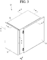
- the entrance refrigerator 10 may include a cabinet 11 partially embedded in an outer wall 1 (e.g., an entrance/front wall of a dwelling/building), an outer door 12 for opening and closing an outer opening 114 provided at a front end of the cabinet 11, an inner door 13 for opening and closing an inner opening 115 provided on a side surface of the cabinet 11, and one or a plurality of cold air supply modules (e.g., assemblies) 20 mounted on a rear surface of the cabinet 11.
- an outer wall 1 e.g., an entrance/front wall of a dwelling/building
- an outer door 12 for opening and closing an outer opening 114 provided at a front end of the cabinet 11
- an inner door 13 for opening and closing an inner opening 115 provided on a side surface of the cabinet 11
- one or a plurality of cold air supply modules (e.g., assemblies) 20 mounted on a rear surface of the cabinet 11.
- the outer opening 114 is provided on a front surface of the cabinet 11 and is defined as a front opening
- the inner opening 115 may be provided on the side surface of the cabinet 11, adjacent to the outer opening 114, and may be defined as a side opening.
- one of the outer opening 114 and the inner opening 115 may be defined as a first opening and the other may be defined as a second opening.
- One of the outer door 12 and the inner door 13 may be defined as a first door and the other may be defined as a second door.
- a range in which the entrance refrigerator 10 is mounted on the outer wall 1 partitioning the indoor area and outdoor area may include the entrance refrigerator 10 being attached (e.g., embedded, connected) to a wall that partitions multiple indoor spaces, including a first indoor space and a second indoor space, or a wall that partitions an indoor area and an outer corridor.
- the entrance refrigerator 10 may be attached/embedded in a wall formed between an entrance door and a middle door that separates the entrance and a room of a home, such as a kitchen. In this case, when an article is input in the entrance, the article may be taken out in the kitchen on the other side.
- the space where the inner door 13 is exposed is defined as a first space
- the space where the outer door 12 is exposed is defined as a second space.
- the first space is an indoor space
- the second space is an outdoor space.
- the space to which the door that is opened to store the delivery service article is exposed may be one of the indoor space and the outdoor space, and the space to which the door that is opened to take out the delivered article is exposed may be the indoor space.
- the entrance refrigerator 10 may further include a heat dissipation cover 15 covering a rear surface of the cold air supply module 20 and an external air guide 16 guiding a flow of heat dissipation air discharged through the heat dissipation cover 15.
- a pair of cold air supply modules 20 are arranged up and down, and a pair of heat dissipation covers 15 cover the cold air supply modules 20, respectively.
- the external air guide 16 may be disposed between the pair of heat dissipation covers 15 disposed up and down and may function to guide the flow of heat dissipation air discharged from the lower heat dissipation cover 15.
- the pair of cold air supply modules 20 may be defined as an upper first cold air supply module and a lower second cold air supply module.
- a structure in which a single cold air supply module 20 is disposed at the center of a rear surface of the cabinet 11 also falls within the scope of the present disclosure, in which the external air guide 16 may not be necessary.
- the heat dissipation cover 15 may have a hexahedral shape, a front surface thereof may be open, and a flange may be bent extending from the open front surface and may be fixed to a rear surface of the cabinet 11.
- a plurality of air vents may be formed only on rear, left, and right surfaces excluding the upper and lower surfaces of the heat dissipation cover 15.
- indoor air may flow into the heat dissipation cover 15 through the air vent formed on the rear surface of the heat dissipation cover 15, and after heat exchange, the air may be discharged to the outside of the heat dissipation cover 15 through the air vents formed on the left surface and the right surface of the heat dissipation cover 15.
- the entrance refrigerator 10 may further include a guide plate 17 disposed on a rear side in the cabinet 11.
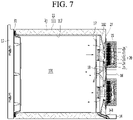
- the guide plate 17 may be a partition member partitioning the inner space (e.g., interior space) of the cabinet 11 into a cold air generating compartment 102 (see FIG. 7 ) in which the cold air supply module 20 is accommodated and a storage compartment 101 in which a delivery service article is stored.
- the entrance refrigerator 10 may further include a drain pan 14 and a drain hose 141 mounted at a lower end of the rear surface of the cabinet 11.
- the drain hose 141 extends from the bottom of the cold air generating compartment 102 to the drain pan 14 through the lower end of the rear surface of the cabinet 11. Therefore, condensate water collected at the bottom of the cold air generating compartment 102 is transported to the drain pan 14 through the drain hose 141 (e.g., the condensate water is collected by the drain pan 14).
- At least the front surface of the outer door 12 is exposed to the outdoor area and a courier that is authenticated may open the outer door 12.
- a front surface of the outer door 12 may be coplanar with or slightly protrude from, the front surfaces of the third storage 5 and second storage 6.
- the front surface of the outer door 12 may be designed to be coplanar with or slightly protrude from the outer wall 1.
- the outer door 12 may be provided without a separate handle structure, in order to prevent easy access by a person, including a person who is not allowed access.
- the controller installed in the control panel 4 or the entrance refrigerator 10 may release a locked state of the outer door 12 and the controller operates a separate driving unit for pushing the outer door 12 so that the outer door 12 rotates forward by a predetermined angle, so that the courier may easily open the outer door.
- the controller may return the outer door to a locked state.
- a distance M from a front end of the cabinet 11 to a left surface of the inner door 13 may correspond to a thickness of the outer wall 1.
- a hinge of the inner door 13 may be installed at the cabinet 11 or may be installed in a portion other than the cabinet 11 including the outer wall 1. The hinge of the inner door 13 may allow the inner door 13 to rotate about the hinge between an open position and a closed position.
- a hinge 124 of the inner door 12 may also be installed at the cabinet 11 or may be installed at a portion other than the cabinet 11 including the outer wall 1.
- the hinge of the inner door 12 may allow the inner door 12 to rotate about the hinge between an open position and a closed position.
- the cabinet 11 includes an outer case 111 forming an appearance, an inner case 112 positioned inside the outer case 111 to define the storage compartment 101, and a heat insulating material 113 filling a space between the outer case 111 and the inner case 112.
- a plurality of protrusions 112i may protrude from a bottom of the inner case 112.
- the plurality of protrusions 112i may extend from a front end to a rear end of the inner case 112 and protrude upward from the bottom of the inner case 112.
- the plurality of protrusions 112i may be arranged to be spaced apart from each other at a predetermined interval in a widthwise direction of the inner case 112.
- each of the plurality of protrusions 112i may be formed as a line protruding upwards from the bottom of the inner case 12, starting substantially from the outer opening 114 to an opposite side of the inner case 12.
- the plurality of protrusions 112i may have a circular (e.g., dot) or hemispherical shape and may be arranged at a predetermined interval so as to come into point contact with a bottom surface of a delivery service article, thereby reducing a frictional force.
- an outer gasket 31 is mounted on a front surface of the cabinet 11 corresponding to the edge of the outer opening 114
- an inner gasket 32 is mounted on a side surface of the cabinet 11 corresponding to the edge of the inner opening 115.
- the outer gasket 31 and the inner gasket 32 may be made of a material known in the art (i.e., the field of refrigeration and heating).
- an inner air guide 18 is mounted on a rear surface of the guide plate 17 to guide cold air supplied from the cold air supply module 20 to the storage compartment 101.
- the cold air supply module 20 includes a cold air supply unit to which a thermoelectric element is applied.
- a thermoelectric element When a current is supplied (e.g., applied), one surface (e.g., a first surface) of the thermoelectric element acts as an endothermic surface absorbing heat as a temperature is decreased, and the other surface (e.g., a second surface opposite to the first surface) thereof acts as an exothermic surface dissipating heat as a temperature is increased.
- the cold air supply module 20 may include a thermoelectric element 21, a cold sink 22 attached to the endothermic surface of the thermoelectric element 21, a heat sink 24 attached to the exothermic surface of the thermoelectric element 21, a heat absorption fan 23 placed (e.g., positioned) in front of the cold sink 22, a heat dissipation fan 25 placed (e.g., positioned) behind the heat sink 24, and an insulation block 26 surrounding the edges of the thermoelectric element 21.
- the cold air supply module 20 may be mounted in a mounting hole formed on the rear surface of the cabinet 11.
- a first cold air supply module may be disposed at a lower portion of the rear surface of the cabinet 11 and a second cold air supply module may be mounted at a position/point on the rear surface of the cabinet corresponding spaced apart upward from the first cold air supply module.
- the inner air guide 18 may be located between a heat absorption fan of the first cold air supply module and a heat absorption fan of the second cold air supply module. Due to the inner air guide 18, cold air flowing by the heat absorption fan of the first cold air supply module and cold air flowing by the heat absorption fan of the second cold air supply module may not be mixed and supplied to the storage compartment.
- At least one or both of the heat absorption fan 23 and the heat dissipation fan 25 may be an axial flow fan or a centrifugal fan.
- Each cold sink 22 includes a sink body and a plurality of heat exchange fins arranged on a front surface of the sink body.
- a rear surface of the sink body is in close contact with the front surface of the thermoelectric element 21, the heat exchange fins may be perpendicular to the front surface of the sink body.
- the plurality of heat exchange fins are spaced apart from each other in a widthwise direction of the sink body. Therefore, cold air inside the storage compartment 101 pulled in by the heat absorption fan 23 hits the front surface of the sink body and flows in an up-down direction through flow paths formed between the plurality of heat exchange fins in a distributed manner.
- the cold air cooled while exchanging heat with the cold sink 22 passes through a discharge grille 171 (see FIG. 8 ) formed at the guide plate 17 along the inner air guide 18 and then is supplied to the storage compartment 101.
- the heat sink 24 may include a sink body whose rear surface is attached to the exothermic surface of the thermoelectric element 21 and a plurality of heat exchange fins extending from a front surface of the sink body.
- the heat sink 24 Since the heat sink 24 must have a larger heat exchange amount than the cold sink 22, the heat sink 24 may have a larger volume than the cold sink 22, and a heat transfer unit such as a heat pipe may be additionally installed therein. This is due to physical properties that a cooling capacity of the thermoelectric element decreases as a temperature difference between the endothermic surface and the exothermic surface increases. Therefore, in order to maximize the cooling capacity of the thermoelectric element 21, a heat dissipation capacity of the heat sink 24 is set larger than that of the cold sink 22.
- the heat exchange fins of the heat sink 24 extend in a horizontal direction and are spaced apart from each other in a vertical direction, ambient air (e.g., indoor air) pulled in by the heat dissipation fan 25 hits (e.g., contacts) the surface of the sink body of the heat sink 24 and then dividedly flow in a left-right direction.
- ambient air e.g., indoor air
- the heat dissipation air dividedly flowing to the left and right after hitting the heat sink 24 at the lower side so as to be heat-exchanged hits a bottom surface of the external air guide 16 and is guided to flow dividedly to the left and right of the heat dissipation cover 15.
- condensate water formed on a surface of the cold sink 22 flows to the bottom of the cold air generating compartment 102 and is collected to a drain pan 14 through a drain hose 141.
- the drain hose 141 extends to the drain pan 14 from the bottom of the inner case 112, which defines the bottom of the cold air generating compartment 102, through the cabinet 11.
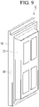
- FIG. 9 is a rear perspective view of an outer door of an entrance refrigerator.
- the outer door 12 of the entrance refrigerator 10 may include a door body 121 and a door liner 122 protruding from a rear surface of the door body 121.
- the door liner 122 may encompass an entire rear surface of the door body 121 or may encompass less than an entire rear surface of the door body 121, such as shown in FIG. 9 .
- the door body 121 may be formed of a metal having a fireproofing function that may tolerate a flame when a fire breaks out in the outdoor corridor.
- the door body 121 may be filled with a fire resistant block.
- the door liner 122 is a portion led into (e.g., extends into) the storage compartment 101 through the outer opening 114 when the outer door 12 is closed. Therefore, the door liner 122 may be filled with insulation foam so that cold air of the storage compartment 101 is not leaked to the outside by heat conduction.
- the outer gasket 31 (see FIG. 7 ) surrounding the edges of the outer opening 114 is in close contact with the rear surface of the door body 121. Specifically, the outer gasket 31 is in close contact with the edges of the door liner 122, thereby blocking leakage air from within the entrance refrigerator 10, including hot air or cold air.
- the hinge 124 is mounted on one surface of the door body 121 (or one surface of the outer door), and a latch recess 123 may be provided on the other surface of the door body 121 (or the other surface of the outer door).
- a door latch is inserted into the latch recess 123 to maintain the outer door 12 in a locked state, and the door latch may be provided in a partition 7 partitioning the entrance refrigerator 10 and the entrance door 3.
- the door latch may be mounted in a horizontal direction on a side surface of the partition 7 facing the other side surface of the door body 121 and may be drawn out from the partition 7 or drawn into the partition 7.
- the door latch may be installed to be drawn in or out from the door body 121 and the latch recess may be provided on a side surface of the partition 7.
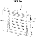
- FIG. 10 is a rear perspective view of an inner door of the entrance refrigerator.
- the inner door 13 of the entrance refrigerator 10 may include a door body 131 and a door liner 132 provided on a rear surface of the door body 131.
- the door body 131 and the door liner 132 may be formed of a plastic material and may be filled with a heat insulating material therein.
- the door body 131 may be formed of a metal depending on design conditions.
- the door liner 132 protrudes from the rear surface of the door body 131 by a predetermined thickness, and when the inner door 13 is closed, the door liner 132 is led into (e.g., positioned in) the storage compartment 101 through the inner opening 115.
- the inner gasket 32 surrounding the edges of the inner opening 115 is in close contact with the rear surface of the door body 131 corresponding to the edges of the door liner 132.
- a hinge 133 is mounted on one side (e.g., a first side) of the door body 131, and the hinge 133 may be fixed to the outer wall 2 or may be fixed to the cabinet 11. Since a front end of the cabinet 11 is embedded in the outer wall 2, the one side (e.g., first side) of the inner door 13, that is, the side on which the hinge 133 is mounted, may be spaced apart from the front end of the cabinet 11 by a predetermined distance (M: see FIG. 3 ).
- the other side (e.g., second side) of the inner door 13 corresponding to the opposite side of the side on which the hinge 133 is mounted may be located at a rear side with respect to the rear end of the cabinet 11. That is, the side end portion defining the other side of the inner door 13 may extend further to a rear than a rear end of the cabinet 11 so as to be adjacent to the third storage 8. According to this structure, the components provided on the rear surface of the cabinet 11 including the heat dissipation cover 15, the drain pan 14, and the external air guide 16 are not exposed to the outside.
- a rear surface portion of the door body 131 may include a left rear surface portion from one side of the door body 131 to one side of the door liner 132, a right rear surface portion from the other side of the door body 131 to the other side of the door liner 132, an upper rear surface portion 138 from an upper end of the door body 131 to an upper end of the door liner 132, and a lower rear surface portion 139 from a lower end of the door body 131 to a lower end of the door liner 132.
- the right rear surface portion may include a first right rear surface portion 134 in close contact with the side of the cabinet 11 when the inner door 13 is closed, and a second right rear surface portion 135 from the edge of the first right rear surface portion 134 to the other side of the door body 131.
- a latch recess 136 may be formed at the first right rear surface portion 134, and a door latch may be provided in the cabinet 11 corresponding to the latch recess 136. That is, a locking device for locking the inner door 13 may be provided on the first right rear surface portion 134 and the cabinet 11 corresponding thereto.
- the second right rear surface portion 135 is a portion extending further from the rear end of the cabinet 11 to the rear side, which serves to shield a space between the rear surface of the cabinet 11 and the first storage 8. That is, the second right rear surface portion 135 may extend from the first right rear surface portion 134.
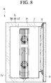
- a vertical width L1 of the second right rear surface portion 135 may be formed smaller than a vertical width L2 of the lower rear surface portion 139 (see FIG. 10 ). This is because, as shown in FIG. 8 , the length from the lower end of the side of the cabinet 11 to the lower end of the inner opening 115 is greater than a thickness of the cabinet 11.
- the lower end of the inner opening 115 is formed higher than the bottom of the storage compartment 101, so that when the inner door 13 is opened, a phenomenon that cold air that stays on the bottom of the storage compartment 101 is leaked to the outside through the inner opening 115 may be minimized, thereby minimizing air leakage (e.g., loss of cold air).
- the lower end of the inner opening 115 may also be designed higher than the bottom of the storage compartment 101.
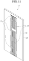
- FIG. 11 is a front perspective view of a guide plate of an entrance refrigerator and FIG. 12 is a rear perspective view of the guide plate.
- the guide plate 17 may include a plate body 172 having a rectangular shape, a bent portion 173 bent backward (e.g., extending backward or rearward) along the edges of the plate body 172, and at least a pair of reinforcing ribs 174 protruding from a rear surface of the plate body 172 and extending from an upper end of the plate body 172 to a lower end thereof.
- the bent portion 173 is in close contact with an inner surface of the inner case 112.
- a distance from a left edge of the plate body 172 to one of the pair of reinforcing ribs 174 may be equal to a distance from a right edge of the plate body 172 to the other of the pair of reinforcing ribs 174.
- a plurality of grilles may be arranged to be spaced apart from each other in an up-down direction, i.e., in a lengthwise direction of the plate body 171, on the plate body 172 corresponding to between the pair of reinforcing ribs 174.
- the grilles may be a structure including an opening formed at the plate body 172 and a plurality of vertical ribs formed in the opening.
- the plurality of vertical ribs may be spaced apart from each other in a widthwise direction of the opening that defines the grilles.
- the plurality of grilles may include a plurality of discharge grilles 171 formed at a central portion of the plate body 172, an upper edge portion of the plate body 172, and a lower edge portion of the plate body 172, and a plurality of intake grilles 175 formed between the vertically adjacent discharge grilles 171.
- the plurality of discharge grilles 171 may include an upper discharge grille formed near the upper edge of the plate body 172, a central discharge grille formed at the center of the plate body 172, and a lower discharge grille formed near the lower edge of the plate body 172.
- a vertical length of the opening defining the central discharge grille may be designed to be twice a vertical length of the opening that defines the upper discharge grille, and a vertical length of the opening that defines the upper discharge grille may be designed to be equal to a vertical length of the opening that defines the lower discharge grille.
- the plurality of intake grilles 175 may include an upper intake grille formed between the upper discharge grille and the central discharge grille and a lower intake grille formed between the central discharge grille and the lower discharge grille.
- the upper intake grille and the lower intake grille may be designed to have the same size or may have different sizes.
- the heat absorption fan 23 of the cold air supply module 20 may be disposed on the rear side of the plurality of intake grilles 175.
- a support rib 176 extends along the edge of the opening that defines the intake grille 175 to form a rectangular fan accommodating portion. Further, the support rib 176 may extend along an entire periphery of the edge of the opening that defines the intake grille 175 to form the rectangular fan accommodating portion. In addition, a portion of a front surface of the heat absorption fan 23 is accommodated in the fan accommodating portion defined by the support rib 176.
- the inner air guide 18 may be mounted on a rear surface of the plate body 172 corresponding to (e.g., at, positioned on) the center of the central discharge grille.
- cold air of the storage compartment 101 is introduced into the cold air generating compartment 102 through the upper intake grille and the lower intake grille to hit (e.g., contact) the surface of the cold sink 22.
- the cold air that hits the cold sink 22 is lowered in temperature through heat exchange and then dividedly flow in an up-down direction of the cold sink 22. A part of the cold air flowing in the up-down direction of the cold sink 22 flows back into the storage compartment 101 through the upper discharge grille and the lower discharge grille.
- intake and discharge flow paths of the cold air may be reversed according to types of the heat absorption fan 23, in which case the intake grilles may function as discharge grilles and the discharge grilles may function as intake grilles.
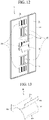
- FIG. 13 is a rear perspective view of the inner air guide of an entrance refrigerator.
- the inner air guide 18 may include an upper guide 181 extending to be rounded upward (e.g., curved upwards) from a front end toward a rear end, a lower guide 182 extending to be rounded downward (e.g., curved downwards) from the front end toward the rear end thereof, and a flange 183 extending vertically from the side of the front end where the upper guide 181 and the lower guide 182 meet.
- the front end (e.g., base) where the upper guide 181 and the lower guide 182 meet may be substantially planar and may extend in a horizontal direction. Further, the upper guide 181 and the lower guide 182 may be symmetric about the front end where the upper guide 181 and the lower guide 182 meet.
- the front end of the upper guide 181 may meet the front end of the lower guide 182 to form a single body. That is, the inner air guide 18 may be formed of a singular unitary body having an upper guide 181 and a lower guide 182, the upper guide 181 and the lower guide 182 meet at a single point, and the upper guide 181 and the lower guide 182 may be curved in opposite directions from the single point.
- the upper guide 181 and the lower guide 182 may be rounded or inclined in a vertically symmetrical shape with respect to a horizontal surface where front ends of the upper guide 181 and the lower guide 182 meet, i.e., a horizontal surface that vertically bisects the inner air guide 18.
- the upper guide 181 may be rounded in a direction in which a slope of a tangent passing through a rear surface of the upper guide 181 increases from the front end toward the rear end.
- the upper guide 181 and the lower guide 182 may be inclined at the same angle to an upper side and a lower side from the horizontal plane, the upper guide 181 and the lower guide 182 meeting (e.g., adjoining) at the horizontal plane, and the horizontal plane bisects the inner air guide 18 vertically (e.g., in an up and down direction).
- the rear surface of the upper guide 181 and the rear surface of the lower guide 182 may refer to two surfaces facing each other (or extending away from each other, as shown in FIG. 13 ), and the opposite surfaces of the rear surfaces may be defined as a front surface of the upper guide 181 and a front surface of the lower guide 182, respectively.
- the flange 183 extends from the left and right ends of the upper guide 181 and the lower guide 182 and is coupled to the pair of reinforcing ribs 174 formed on the rear surface of the guide plate 17.
- the front end of the inner air guide 18 may be disposed at a point that bisects the central discharge grille of the guide plate 17 up and down. Accordingly, cold air forcedly flowing by the upper heat absorption fan 23 and cold air forcedly flowing by the lower heat absorption fan 23 are discharged to the storage compartment 101 substantially uniformly through the central discharge grille.
- the flange 183 may be fixedly mounted to the reinforcing rib 174 by a screw or other fastener passing through the reinforcing rib 174.
- the flange 183 may be attached to the reinforcing rib 174 by an adhesive member, brazing, welding or any other joining method.
- the flange 183 may not be provided, and the front ends where the upper guide 181 and the lower guide 182 meet may be attached directly to the rear surface of the guide plate 17, such as by fastening with fasteners, adhesive bonding, brazing or welding.
- a rear end of the upper surface of the lower guide 182 may be provided with an interference preventing recess 182a, and a function of the interference preventing recess 182a will be described in detail with reference to the drawings below.
- the interference preventing recess 182a is provided at a rear end of the lower guide 182, opposite to the front end where the upper guide 181 meets the front end of the lower guide 182. Further, the interference preventing recess 182a may extend substantially an entire width of the rear end of the lower guide 182, or may extend less than an entire width of the rear end of the lower guide 182.
- FIG. 14 is a cutaway perspective view showing a rear wall of an inner case of a cabinet of an entrance refrigerator and FIG. 15 is a rear perspective view of the rear wall of the inner case.
- a through-hole in which one or a plurality of cold air supply modules 20 are mounted is provided on a rear wall of the inner case 112 of the cabinet 11 of the entrance refrigerator 10.
- an upper through-hole 112a and a lower through-hole 112b may be provided on the rear wall of the cabinet 11.
- a center recess 112f having a predetermined width may be provided to extend from an upper end of the rear wall of the inner case 112 to a lower end of the inner case 112 (e.g., the center recess 112f extend an entire distance from an upper end of the rear wall of the inner case 112 to a lower end of the inner case 112).
- the center recess 112f may be a portion of the rear wall of the inner case 112, which is recessed or stepped backward, and may be formed by a forming process, such as a deforming process (e.g., pressing, molding, etc.).
- An upper end of the upper through-hole 112a is spaced apart by a predetermined distance downward (e.g., is spaced downward from) from an upper end of the center recess 112f, and a lower end of the lower through-hole 112b is spaced apart by a predetermined distance upward (e.g., is spaced upward from) from a lower end of the center recess 112f.
- an upper guide portion 112g rounded in a direction protruding rearward or stepped a plurality of times in a stairway (e.g., stair-like or stair) shape from the upper end of the center recess 112f toward the upper end of the upper through-hole 112a is defined.
- a lower guide portion 112h is provided at a portion from the lower end of the center recess 112f to the lower end of the lower through-hole 112b.
- the upper guide portion 112g and the lower guide portion 112h may be understood as portions provided to guide a flow of air pulled in by the intake fan 23 and ascends or descends along the cold sink 22 toward the discharge grille 171 of the guide plate 17.
- a guide protrusion 112c may be provided for guiding a flow of condensate water, and the guide protrusion 112c may protrude from the rear wall of the inner case 112 corresponding to between the upper through-hole 112a and the lower through-hole 112b.
- the guide protrusion 112c may be formed to have a width narrower toward the upper through-hole 112a.
- the guide protrusion 112c includes a left inclined portion 112d and a right inclined portion 112e, and an upper end of the left inclined portion 112d and an upper end of the right inclined portion 112e meet to form a peak. That is, the guide protrusion 112c may form a triangular shape with the left inclined portion 112d and the right inclined portion 112e.
- left inclined portion 112d and the right inclined portion 112e may extend from a point where they are spaced apart upward from the lower through-hole 112b.
- the guide protrusion 112c may extend vertically upward with a predetermined width from the upper end of the lower through-hole 112b and extend to have a narrower width, starting from a point where the left inclined portion 112d and the right inclined portion 112e are formed (e.g., begin).
- the condensate water or the defrost water flows down to the bottom of the inner case 112 along a left flow path 112j formed at a left edge of the center recess 112f and a left edge of the guide protrusion 112c and a right flow path 112k formed at a right edge of the center recess 112f and a right edge of the guide protrusion 112c.
- the condensate water or the defrost water flowing down to the upper end of the guide protrusion 112c is divided at the left inclined portion 112d and the right inclined portion 112e to flow to the left flow path 112j and the right flow path 112k.
- a drain hole 112m is formed at a point where the rear wall and the bottom surface of the inner case 112 meet, and one end of the drain hose 141 is connected to the drain hole 112m. Therefore, the condensate water or the defrost water flowing down to the bottom of the inner case 112 is collected to the drain pan 14 along the drain hose 141.
- left inclined portion 112d and the right inclined portion 112e may extend from the upper end of the lower through-hole 112b, so that the guide protrusion 112c may have a triangular protrusion shape.
- cold air introduced into the cold air generating compartment 102 from the storage compartment 101 by the heat absorption fan 23 directly hits (e.g., contacts) the front surface of the cold sink 22 and then dividedly flows to the upper side and the lower side.
- a flow rate of the cold air hitting the front surface of the cold sink 22 is relatively low from the center of the front surface of the cold sink 22 toward the both side ends.
- a flow resistance may occur as the cold air ascending after hitting the surface of the cold sink of the cold air supply module 20 mounted in the lower through-hole 112b pushes up the condensate water or the defrost water flowing down from the upper cold sink 22.
- the flow resistance acting on the condensate water or the defrost water that flows down may be minimized by dispersing the flow of the condensate water or the defrost water to the left flow path 112j and the right flow path 112k.
- FIG. 16 is an enlarged cross-sectional view of part A of FIG. 7 .
- cold air e.g., intake air
- the cold air pulled into the cold air generating compartment 102 is changed in a flow direction by 180 degrees by the upper guide 181 and the lower guide 182. That is, the cold air pulled by the heat absorption fans hits the front surface of the sink body of the cold sink 22 and descends, and then is dispersed up and down.
- the cold air dispersed up and down is changed in flow direction toward the storage compartment by the upper guide 181 and the lower guide 182.
- the cold air changed in flow direction is discharged to the storage compartment 101 through the guide plate 17.
- a rear end of the upper guide 181 of the inner air guide 18 is spaced apart from the rear wall of the inner case 112 defining the center recess 112f. This is to prevent the flow of the condensate water or the defrost water flowing down along the rear wall of the inner case 112 as indicated by the dotted arrow from being interfered by the upper guide 181.
- the condensate water or the defrost water moves to the front end of the upper guide 181 along the upper surface of the upper guide 181.
- the condensate water or the defrost water flowing along the upper surface of the upper guide 181 flows down to the bottom of the storage compartment 101 along the guide plate 17.
- the condensate water flowing down to the bottom of the inner case 112 does not flow toward the drain hole 112m formed at the bottom of the cold air generating compartment 102 but remains at the bottom of the storage compartment 101. This phenomenon may cause mold to occur inside the storage compartment 101 and to cause odor.
- the rear end of the lower guide 182 may be in contact with the guide protrusion 112c, and the interference preventing recess 182a formed on the upper surface of the rear end of the lower guide 182 may be defined as a recess accommodating the guide protrusion 112c. Therefore, a width of the interference preventing recess 182a may be formed to have a size corresponding to the width of the guide protrusion 112c.
- the left edge and the right edge of the rear end of the lower guide 182 are spaced apart from the rear wall of the inner case 112 defining the left flow path 112j and the right flow path 112k.
- the front surface of the rear wall of the inner case 112 from the lower end of the upper through-hole 112a and the upper end of the lower through-hole 112b may be formed to be inclined in the form of protruding forward toward a lower side (e.g., inclined toward a lower side).
- the inclined structure may also be applied to the rear wall of the inner case 112 defining the left flow path 112j and the right flow path 112k in the same manner.
- the inclined structure may minimize a phenomenon that the condensate water or the defrost water falling from the cold sink 22 of the first cold air supply module 20 hits directly the cold sink 22 of the second cold air supply module 20 and scatters.
- FIG. 17 is a perspective view of the blocking plate 40 of a storage system for a house entrance according to an embodiment of the present disclosure
- FIG. 18 is a longitudinal cross-sectional view of the blocking plate 40, taken along 18-18 of FIG. 17
- FIG. 19 is a cross-sectional view of a storage system for a house entrance, taken along line 19-19 of FIG. 2
- FIG. 20 is a cross-sectional view of storage system for a house entrance, taken along line 20-20 of FIG. 2 .
- the blocking plate 40 is a plate having a width corresponding to a gap between the rear surface of the entrance refrigerator 10 and the front surface of the first storage 8, a length corresponding to a height of the first storage 8, and a certain (e.g., predetermined) thickness.
- a surface of the blocking plate 40 exposed to the room in a state in which the blocking plate 40 is mounted may be defined as a front surface (or outer surface) of the blocking plate 40 and opposite to the front surface of the blocking plate 40 may be defined as a rear surface (or inner surface) of the blocking plate 40.
- the front surface of the blocking plate 40 may form the same surface as the front surface of the first inner door 8a. That is, the front surface of the blocking plate 40 may form a same plane as the front surface of the first inner door 8a.
- a vertical plane passing through the front surface of the blocking plate 40 and a vertical plane passing through the front surface of the first inner door 8a may be planes spaced apart from each other at a regular (e.g., predetermined) interval.
- the blocking plate 40 includes a plurality of intake holes 41 at a lower end region of the blocking plate 40, and a plurality of discharge holes 42 at an upper end region of the blocking plate 40. That is, the plurality of intake holes 41 are formed at the lower region of the blocking plate 40, and the plurality of discharge holes 42 are formed at the upper region of the blocking plate 40, based on a line that vertically bisects the blocking plate 40 (e.g., a vertical center of the blocking plate 40 may separate the plurality of intake holes 41 from the plurality of discharge holes 42, as may be defined in a vertical axis or vertical direction).
- a filter F is mounted on a rear surface of the blocking plate 40 corresponding to a portion where the plurality of intake holes 41 are provided (e.g., the blocking plate 40 overlaps the plurality of intake holes 41), to filter foreign matter contained in the air pulled in through the plurality of intake holes 41.
- the filter F significantly reduces the amount of the foreign matter flowing into the heat dissipation fan 25 and extends the life of the heat dissipation fan 25.
- the plurality of intake holes 41 may be formed to be inclined upward from the front surface of the blocking plate 40 toward the rear surface of the blocking plate 40. Then, indoor air existing in the entrance flows into the gap between the entrance refrigerator 10 and the third storage 8 and is guided to rise (e.g., in a vertical direction) toward the heat dissipation cover 15 of the entrance refrigerator 10.
- the plurality of discharge holes 42 may be formed to be upwardly inclined (e.g., in a vertical direction) from the rear surface of the blocking plate 40 toward the front surface of the blocking plate 40. That is, the plurality of discharge holes 42 may be declined from the front surface of the blocking plate 40 toward the rear surface of the blocking plate 40.
- the plurality of discharge holes 42 may be formed in a direction different than the plurality of intake holes 41. Then, heat, which is released from the heat dissipation cover 15 and rises, may be discharged, while continue to rise toward a ceiling of the entrance in the gap. Therefore, the flow resistance of the exhaust air is minimized and a phenomenon that heat directly reaches an indoor occupant may be prevented.
- the ceiling of the entrance is provided with a duct penetrating through a wall partitioning an indoor area and outdoor area, and air discharged toward the ceiling of the entrance may be released to the outside through the duct.
- the heat sink 24 and the heat dissipation fan 25 of the cold air supply modules 20 may be defined as an exothermic part (or heat liberation part, heat dissipation part), and the cold sink 22 and the heat absorption fan 23 may be defined as an endothermic part (heat absorption part). Therefore, the cold air supply modules 20 may be understood to include the thermoelectric element 21, the endothermic part, and exothermic part (or a heat dissipation part). The exothermic part is exposed to the outside of the rear surface of the cabinet 11, and the endothermic part is accommodated in the cabinet 11.
- the third storage 5, the second storage 6 and the first storage 8 described above are not restricted in order, and it should be noted that any one of the three storages 5, 6, and 8 is the first storage, another is the second storage, and the other is the third storage.
Landscapes
- Engineering & Computer Science (AREA)
- Physics & Mathematics (AREA)
- Mechanical Engineering (AREA)
- Thermal Sciences (AREA)
- General Engineering & Computer Science (AREA)
- Chemical & Material Sciences (AREA)
- Combustion & Propulsion (AREA)
- Food Science & Technology (AREA)
- Devices That Are Associated With Refrigeration Equipment (AREA)
- Cold Air Circulating Systems And Constructional Details In Refrigerators (AREA)
Description
- The present disclosure relates to a storage system for a house entrance.
- Recently, delivery services for delivering articles (or goods) to a certain place has been commonplace. In particular, when the article to be delivered is fresh food, the fresh food may be stored and delivered in a refrigerator or in a warmer, the refrigerator or warmer may be provided in a delivery vehicle, in order to prevent the food from being spoiled or cooled.
- Food is generally delivered in a packing material to maintain a cooling or warming state. The packing material is formed of environmental pollutants, such as Styrofoam® or an extruded polystyrene foam or other insulating material. There is an increasing need to reduce the environmental pollutants, including socially and economically.
- Additionally, if a user is at home at a delivery time, the user may directly receive food from a courier (i.e., a delivery person) face to face, but if the user is not at home, such as when the delivery time is too early or late, it may be difficult for the user to directly receive food from the courier face to face.
- Therefore, there is a need for food to be received even if the user does not come into direct contact with a courier and there is a need for food not to be spoiled or to be overly cooled until the food is finally delivered to the user. That is, there is a need to maintain the food in the manner in which it was delivered, including the temperature it was delivered, in order to preserve its freshness or to keep the food at a desired temperature for consumption.
- In order to solve these above problems, recently, a product, such as a refrigerator, is installed at an entrance (e.g., front door) of a user's residence or other place, so that the courier may store the delivered food in the refrigerator to keep the food fresh and the user may access the refrigerator at a convenient time to receive the food.
- A related art below discloses an entrance refrigerator provided to be mounted on an entrance door or embedded (e.g., provided) in a wall that borders an entrance hallway.
- Related art:
Korean Utility Model Registration No. 20-0357547, dated July 19, 2004 - The entrance refrigerator embedded (e.g., provided) in a wall disclosed in the related art has the following problems.
- First, although a conventional cooling device is described as being installed on the bottom of a storage compartment, there is no reference to a type or design structure of a specific cooling device.
- Second, it is described that heat generated in the cooling device is discharged to an outdoor corridor. In the case of the structure, outsiders that pass by the corridor may be in direct contact with heat to cause discomfort.
- Third, in summer, heat generated in the cooling device may be discharged to the outdoor corridor to increase a temperature of the air in the corridor.
- Fourth, when heat generated in the cooling device is discharged to an indoor entrance, if a height of a discharge port is lower than a height of a dweller, heat may be in direct contact with the dweller to cause discomfort.
- The present disclosure is proposed to improve a technical problem of the wall-embedded entrance refrigerator of the related art.
-
JP 2016 130609 A JP H10 245095 A US 2018/274825 A1 discloses a refrigerator including an inner case having a storage chamber, which is cooled by a thermoelectric module. - The invention defined by the appended independent claim achieves these and other advantages in accordance with the purpose of the disclosure. In the following description, there is provided a storage system for a house entrance including an entrance refrigerator, a first storage placed at a position spaced apart from a rear surface of the entrance refrigerator, and a blocking plate covering a gap formed between the entrance refrigerator and the first storage.
- An intake hole is provided at a lower region of the blocking plate, a discharge hole is provided at an upper region of the blocking plate, and the intake hole and the discharge hole may extend to be inclined upwardly (e.g., inclined in a vertical direction).
- A filter may be mounted on one surface of the blocking plate in which the intake hole is provided, and the filter may be configured to filter foreign matter included in air introduced through the intake hole.
- The storage system may further include a second storage positioned on one of the upper side and the lower side of the entrance refrigerator, and a third storage positioned on the other of the upper side and the lower side of the entrance refrigerator.
- According to the storage system for a house entrance a courier may deliver a delivery article without having to come into contact with a home owner in an outdoor area.
- In addition, since the cold air supply module including a thermoelectric element is used as a means for maintaining a temperature inside the refrigerator at a refrigerating temperature or a warming temperature, a size of a storage space is maximized and a size of a space in which the cold air supply module is accommodated may be minimized.
- In addition, since heat generated in the cold air supply module is discharged upward in an indoor area, a phenomenon that a person passing by an outdoor corridor is uncomfortable does not occur.
- The accompanying drawings, which are included to provide a further understanding of the disclosure and are incorporated in and constitute a part of this application, illustrate embodiments of the disclosure and together with the description serve to explain the principle of the disclosure. In the drawings:
-
FIG. 1 is a front perspective view of an entrance equipped with an entrance refrigerator -
FIG. 2 is a perspective view showing the inside of an entrance taken along line 2-2 ofFIG. 1 . -
FIG. 3 is a front perspective view of an entrance refrigerator -
FIG. 4 is a rear perspective view of the entrance refrigerator. -
FIG. 5 is an exploded perspective view of the entrance refrigerator. -
FIG. 6 is a cross-sectional cutaway perspective view of the entrance refrigerator taken along line 6-6 ofFIG. 3 . -
FIG. 7 is a side cross-sectional view of the entrance refrigerator taken along line 7-7 ofFIG. 3 . -
FIG. 8 is a longitudinal cross-sectional view of the entrance refrigerator taken along line 8-8 ofFIG. 3 . -
FIG. 9 is a rear perspective view of an outer door of an entrance refrigerator according to an embodiment of the present disclosure. -
FIG. 10 is a rear perspective view of an inner door of an entrance refrigerator -
FIG. 11 is a front perspective view of a guide plate of an entrance refrigerator -
FIG. 12 is a rear perspective view of the guide plate. -
FIG. 13 is a rear perspective view of an inner air guide of an entrance refrigerator -
FIG. 14 is a cutaway perspective view showing a rear wall of an inner case of a cabinet of an entrance refrigerator -
FIG. 15 is a rear perspective view of a rear wall of the inner case. -
FIG. 16 is an enlarged cross-sectional view of a portion A ofFIG. 7 . -
FIG. 17 is a perspective view of a blocking plate of a storage system for a house entrance according to an embodiment of the present disclosure. -
FIG. 18 is a longitudinal cross-sectional view of a blocking plate, taken along line 18-18 ofFIG. 17 . -
FIG. 19 is a cross-sectional view of a storage system for a house entrance, taken along line 19-19 ofFIG. 2 . -
FIG. 20 is a cross-sectional view of a storage system for a house entrance, taken along line 20-20 ofFIG. 2 . - Hereinafter, a storage system for a house entrance according to the invention will be described in detail with reference to the accompanying drawings.
-
FIG. 1 is a front perspective view of an entrance equipped with an entrance refrigerator andFIG. 2 is a cutaway perspective view showing an inside of an entrance taken along line 2-2 ofFIG. 1 . - Referring to
FIGS. 1 and2 , an opening is formed on anouter wall 1 partitioning an indoor area and a corridor, and aframe 2 is provided at the edge of the opening. That is, theframe 2 is attached to the opening of theouter wall 1. In addition, anentrance door 3 may be installed inside theframe 2, and anentrance refrigerator 10 may be disposed on a side of the entrance door 3 (e.g., theentrance refrigerator 10 may be positioned within the frame and adjacent to the entrance door 3). - A partition or a
partition wall 7 may be formed between theentrance door 3 and theentrance refrigerator 10, and thepartition 7 opens and closes theentrance door 3, which may be a front door. Thepartition 7 may have acontrol panel 4 for controlling opening and closing of theentrance door 3 and opening and closing of a door 12 (seeFIG. 3 ) of theentrance refrigerator 10. - The
control panel 4 may include at least one of a face recognition sensor for recognizing a face of an approaching person, a code reader for recognizing an encryption code of a delivery service article to be stored in theentrance refrigerator 10, a proximity sensor, a controller (e.g., processor, CPU) and a display unit. Further, the at least one face recognition sensor, the code reader, and the proximity sensor of thecode reader 4 may be installed at one side or multiple sides of thecontrol panel 4. A face image of an approaching person, recognized by the face recognition sensor, may be displayed on the display unit of thecontrol panel 4. - In addition, a controller of the
control panel 4 may perform a function of controlling opening and closing of an outdoor side door and an indoor side door of theentrance refrigerator 10, as well as a function of controlling opening and closing of theentrance door 3, according to a result of the face recognition. - For example, the controller of the
control panel 4 may perform a function of opening an outdoor side door of theentrance refrigerator 10 according to a result of recognizing a delivery article and automatically perform a function of locking the outdoor side door when the outdoor side door is recognized to be closed. - In addition, in a state where one of the outdoor side door and an indoor side door of the
entrance refrigerator 10 is open, the controller of thecontrol panel 4 may maintain the other in a closed state. - Alternatively, an independent control panel may be provided for performing the functions on the indoor side door of the entrance refrigerator or the outdoor side door of the
entrance refrigerator 10 described above with respect to thecontrol panel 4. - Additionally, an upper side (e.g., upper portion) of the
entrance refrigerator 10 may be provided with athird storage 5, and a lower side (e.g., lower portion) thereof, below thethird storage 5, may be provided with asecond storage 6. Thethird storage 5 may function as a warmer for storing articles in a warmed state. In addition, thesecond storage 6 may be maintained at room temperature to simply perform a function of storing a delivery service article (e.g., an article not needing to be maintained a particular temperature) or may be maintained at a temperature different from an internal temperature of theentrance refrigerator 10. Alternatively, the second storage may be maintained at a temperature lower than room temperature. - The
third storage 5 may be maintained at a refrigerating temperature or freezing temperature, and thesecond storage 6 may be used as a space maintained at room temperature so as to perform only a function of storing a delivery service article. - Additionally, one or a plurality of
first storages 8 are installed on an indoor entrance side wall corresponding to a rear of theentrance refrigerator 10. Thefirst storage 8 may be adjacent to thethird storage 5 and thesecond storage 6, and in an example not forming part of this invention, between thethird storage 5 and theentrance door 3 and between thesecond storage 6 and theentrance door 3. Thefirst storage 8 may be used as a space for storing shoes, umbrellas, or laundry. - The
third storage 5 has athird case 5c having a third storage compartment formed therein, a thirdouter door 5a selectively opening and closing a third front opening provided on a front surface of thethird case 5c, and a thirdinner door 5b selectively opening and closing a third side opening provided on an indoor side surface of thethird case 5c. - The
second storage 6 may include a second case having a second storage compartment formed therein, a secondouter door 6a selectively opening and closing a second front opening provided on a front surface of the second case, and a secondinner door 6b selectively opening and closing a second side opening provided on an indoor side surface of the second case. - The outer door 12 (see
FIG. 3 ), the thirdouter door 5a, and the secondouter door 6a of theentrance refrigerator 10 are all exposed to the outside, and at least some of them or all of them may be coplanar. That is, some or all of the front surfaces of theouter door 12, the thirdouter door 5a, and the secondouter door 6a may be placed on one vertical surface (e.g., may extend along a same vertical plane). - In addition, the
first storage 8 includes afirst case 8b in which a first storage compartment is provided, and a firstinner door 8a selectively opening and closing a first side opening provided on a side surface of thefirst case 8b. The firstinner door 8a may be defined as a first door or a door. - The first storage compartment may be partitioned into a plurality of storage spaces in an up-down (e.g., vertical) direction by one or a plurality of partitions.
- Additionally, a gap is formed between the
entrance refrigerator 10 and thefirst storage 8, and the gap extends in a vertical direction. Further, theentrance refrigerator 10 may be stacked on thesecond storage 6, and thethird storage 5 may be stacked on theentrance refrigerator 10, such that thethird storage 5, theentrance refrigerator 10 and thesecond storage 6 extend along a same plane and are spaced from thefirst storage 8 by the gap. The gap serves as an indoor air flow path for cooling a heat sink (to be described later) mounted on the rear surface of theentrance refrigerator 10. - A gap formed between the
third storage 5 and theentrance refrigerator 10 and between a rear surface of thesecond storage 6 and a front surface of thefirst storage 8 are shielded by the blockingplate 40. - A structure and function of the blocking
plate 40 will be described in detail with reference to the accompanying drawings below. - Specifically, the
entrance refrigerator 10 may include acabinet 11 partially embedded in an outer wall 1 (e.g., an entrance/front wall of a dwelling/building), anouter door 12 for opening and closing anouter opening 114 provided at a front end of thecabinet 11, aninner door 13 for opening and closing aninner opening 115 provided on a side surface of thecabinet 11, and one or a plurality of cold air supply modules (e.g., assemblies) 20 mounted on a rear surface of thecabinet 11. - Here, the
outer opening 114 is provided on a front surface of thecabinet 11 and is defined as a front opening, and theinner opening 115 may be provided on the side surface of thecabinet 11, adjacent to theouter opening 114, and may be defined as a side opening. - Alternatively, one of the
outer opening 114 and theinner opening 115 may be defined as a first opening and the other may be defined as a second opening. One of theouter door 12 and theinner door 13 may be defined as a first door and the other may be defined as a second door. - In addition, a range in which the
entrance refrigerator 10 is mounted on theouter wall 1 partitioning the indoor area and outdoor area may include theentrance refrigerator 10 being attached (e.g., embedded, connected) to a wall that partitions multiple indoor spaces, including a first indoor space and a second indoor space, or a wall that partitions an indoor area and an outer corridor. - For example, the
entrance refrigerator 10 may be attached/embedded in a wall formed between an entrance door and a middle door that separates the entrance and a room of a home, such as a kitchen. In this case, when an article is input in the entrance, the article may be taken out in the kitchen on the other side. - Therefore, the space where the
inner door 13 is exposed is defined as a first space, and the space where theouter door 12 is exposed is defined as a second space. The first space is an indoor space, and the second space is an outdoor space. - In another aspect, the space to which the door that is opened to store the delivery service article is exposed may be one of the indoor space and the outdoor space, and the space to which the door that is opened to take out the delivered article is exposed may be the indoor space.
- In addition, the
entrance refrigerator 10 may further include aheat dissipation cover 15 covering a rear surface of the coldair supply module 20 and anexternal air guide 16 guiding a flow of heat dissipation air discharged through theheat dissipation cover 15. - In this embodiment, a pair of cold
air supply modules 20 are arranged up and down, and a pair of heat dissipation covers 15 cover the coldair supply modules 20, respectively. In addition, theexternal air guide 16 may be disposed between the pair of heat dissipation covers 15 disposed up and down and may function to guide the flow of heat dissipation air discharged from the lowerheat dissipation cover 15. - The pair of cold
air supply modules 20 may be defined as an upper first cold air supply module and a lower second cold air supply module. - Here, a structure in which a single cold
air supply module 20 is disposed at the center of a rear surface of thecabinet 11 also falls within the scope of the present disclosure, in which theexternal air guide 16 may not be necessary. - The
heat dissipation cover 15 may have a hexahedral shape, a front surface thereof may be open, and a flange may be bent extending from the open front surface and may be fixed to a rear surface of thecabinet 11. - A plurality of air vents may be formed only on rear, left, and right surfaces excluding the upper and lower surfaces of the
heat dissipation cover 15. By this structure, indoor air may flow into theheat dissipation cover 15 through the air vent formed on the rear surface of theheat dissipation cover 15, and after heat exchange, the air may be discharged to the outside of theheat dissipation cover 15 through the air vents formed on the left surface and the right surface of theheat dissipation cover 15. - In addition, the
entrance refrigerator 10 may further include aguide plate 17 disposed on a rear side in thecabinet 11. Theguide plate 17 may be a partition member partitioning the inner space (e.g., interior space) of thecabinet 11 into a cold air generating compartment 102 (seeFIG. 7 ) in which the coldair supply module 20 is accommodated and astorage compartment 101 in which a delivery service article is stored. - In addition, the
entrance refrigerator 10 may further include adrain pan 14 and adrain hose 141 mounted at a lower end of the rear surface of thecabinet 11. Thedrain hose 141 extends from the bottom of the coldair generating compartment 102 to thedrain pan 14 through the lower end of the rear surface of thecabinet 11. Therefore, condensate water collected at the bottom of the coldair generating compartment 102 is transported to thedrain pan 14 through the drain hose 141 (e.g., the condensate water is collected by the drain pan 14). - Additionally, at least the front surface of the
outer door 12 is exposed to the outdoor area and a courier that is authenticated may open theouter door 12. A front surface of theouter door 12 may be coplanar with or slightly protrude from, the front surfaces of thethird storage 5 andsecond storage 6. Alternatively, the front surface of theouter door 12 may be designed to be coplanar with or slightly protrude from theouter wall 1. - The
outer door 12 may be provided without a separate handle structure, in order to prevent easy access by a person, including a person who is not allowed access. When theouter door 12 is provided without a handle structure, if a delivery service article is recognized and authenticated by an authentication unit mounted on one side of theouter door 12 or on thecontrol panel 4, the controller installed in thecontrol panel 4 or theentrance refrigerator 10 may release a locked state of theouter door 12 and the controller operates a separate driving unit for pushing theouter door 12 so that theouter door 12 rotates forward by a predetermined angle, so that the courier may easily open the outer door. - In addition, when the article storage is completed (e.g., the article is stored in the cabinet 11) and the courier/person closes the
outer door 12, the controller may return the outer door to a locked state. - In addition, in
FIG. 3 , a distance M from a front end of thecabinet 11 to a left surface of theinner door 13 may correspond to a thickness of theouter wall 1. A hinge of theinner door 13 may be installed at thecabinet 11 or may be installed in a portion other than thecabinet 11 including theouter wall 1. The hinge of theinner door 13 may allow theinner door 13 to rotate about the hinge between an open position and a closed position. - Further, a
hinge 124 of theinner door 12 may also be installed at thecabinet 11 or may be installed at a portion other than thecabinet 11 including theouter wall 1. The hinge of theinner door 12 may allow theinner door 12 to rotate about the hinge between an open position and a closed position. - In addition, the
cabinet 11 includes anouter case 111 forming an appearance, aninner case 112 positioned inside theouter case 111 to define thestorage compartment 101, and aheat insulating material 113 filling a space between theouter case 111 and theinner case 112. - A plurality of
protrusions 112i (seeFIG. 8 ) may protrude from a bottom of theinner case 112. The plurality ofprotrusions 112i may extend from a front end to a rear end of theinner case 112 and protrude upward from the bottom of theinner case 112. - In addition, the plurality of
protrusions 112i may be arranged to be spaced apart from each other at a predetermined interval in a widthwise direction of theinner case 112. - Since the plurality of
protrusions 112i are formed at the bottom of theinner case 112, when a delivery service article that is heavy is pushed into and received in thestorage compartment 101, the delivery service article may come into contact with the plurality ofprotrusions 112i formed on bottom of theinner case 112, thereby minimizing a frictional force as compared to contacting the entirety of the bottom of theinner case 12. Further, each of the plurality ofprotrusions 112i may be formed as a line protruding upwards from the bottom of theinner case 12, starting substantially from theouter opening 114 to an opposite side of theinner case 12. - The plurality of
protrusions 112i may have a circular (e.g., dot) or hemispherical shape and may be arranged at a predetermined interval so as to come into point contact with a bottom surface of a delivery service article, thereby reducing a frictional force. - In addition, an
outer gasket 31 is mounted on a front surface of thecabinet 11 corresponding to the edge of theouter opening 114, and aninner gasket 32 is mounted on a side surface of thecabinet 11 corresponding to the edge of theinner opening 115. Theouter gasket 31 and theinner gasket 32 may be made of a material known in the art (i.e., the field of refrigeration and heating). - In addition, an
inner air guide 18 is mounted on a rear surface of theguide plate 17 to guide cold air supplied from the coldair supply module 20 to thestorage compartment 101. - Additionally, the cold
air supply module 20 includes a cold air supply unit to which a thermoelectric element is applied. When a current is supplied (e.g., applied), one surface (e.g., a first surface) of the thermoelectric element acts as an endothermic surface absorbing heat as a temperature is decreased, and the other surface (e.g., a second surface opposite to the first surface) thereof acts as an exothermic surface dissipating heat as a temperature is increased. - The cold
air supply module 20 may include athermoelectric element 21, acold sink 22 attached to the endothermic surface of thethermoelectric element 21, aheat sink 24 attached to the exothermic surface of thethermoelectric element 21, aheat absorption fan 23 placed (e.g., positioned) in front of thecold sink 22, aheat dissipation fan 25 placed (e.g., positioned) behind theheat sink 24, and aninsulation block 26 surrounding the edges of thethermoelectric element 21. - Specifically, as shown in
FIG. 7 , the coldair supply module 20, may be mounted in a mounting hole formed on the rear surface of thecabinet 11. In a case where the pair of coldair supply modules 20 are disposed to be spaced apart in an up and down (e.g., vertical) direction, a first cold air supply module may be disposed at a lower portion of the rear surface of thecabinet 11 and a second cold air supply module may be mounted at a position/point on the rear surface of the cabinet corresponding spaced apart upward from the first cold air supply module. - The
inner air guide 18 may be located between a heat absorption fan of the first cold air supply module and a heat absorption fan of the second cold air supply module. Due to theinner air guide 18, cold air flowing by the heat absorption fan of the first cold air supply module and cold air flowing by the heat absorption fan of the second cold air supply module may not be mixed and supplied to the storage compartment. - At least one or both of the
heat absorption fan 23 and theheat dissipation fan 25 may be an axial flow fan or a centrifugal fan. - Each
cold sink 22 includes a sink body and a plurality of heat exchange fins arranged on a front surface of the sink body. A rear surface of the sink body is in close contact with the front surface of thethermoelectric element 21, the heat exchange fins may be perpendicular to the front surface of the sink body. The plurality of heat exchange fins are spaced apart from each other in a widthwise direction of the sink body. Therefore, cold air inside thestorage compartment 101 pulled in by theheat absorption fan 23 hits the front surface of the sink body and flows in an up-down direction through flow paths formed between the plurality of heat exchange fins in a distributed manner. The cold air cooled while exchanging heat with thecold sink 22 passes through a discharge grille 171 (seeFIG. 8 ) formed at theguide plate 17 along theinner air guide 18 and then is supplied to thestorage compartment 101. - Like the
cold sink 22, theheat sink 24 may include a sink body whose rear surface is attached to the exothermic surface of thethermoelectric element 21 and a plurality of heat exchange fins extending from a front surface of the sink body. - Since the
heat sink 24 must have a larger heat exchange amount than thecold sink 22, theheat sink 24 may have a larger volume than thecold sink 22, and a heat transfer unit such as a heat pipe may be additionally installed therein. This is due to physical properties that a cooling capacity of the thermoelectric element decreases as a temperature difference between the endothermic surface and the exothermic surface increases. Therefore, in order to maximize the cooling capacity of thethermoelectric element 21, a heat dissipation capacity of theheat sink 24 is set larger than that of thecold sink 22. - In addition, since the heat exchange fins of the
heat sink 24 extend in a horizontal direction and are spaced apart from each other in a vertical direction, ambient air (e.g., indoor air) pulled in by theheat dissipation fan 25 hits (e.g., contacts) the surface of the sink body of theheat sink 24 and then dividedly flow in a left-right direction. - In particular, the heat dissipation air dividedly flowing to the left and right after hitting the
heat sink 24 at the lower side so as to be heat-exchanged hits a bottom surface of theexternal air guide 16 and is guided to flow dividedly to the left and right of theheat dissipation cover 15. - Additionally, condensate water formed on a surface of the
cold sink 22 flows to the bottom of the coldair generating compartment 102 and is collected to adrain pan 14 through adrain hose 141. Thedrain hose 141 extends to thedrain pan 14 from the bottom of theinner case 112, which defines the bottom of the coldair generating compartment 102, through thecabinet 11. -
FIG. 9 is a rear perspective view of an outer door of an entrance refrigerator. - Referring to
FIG. 9 , theouter door 12 of theentrance refrigerator 10 may include adoor body 121 and adoor liner 122 protruding from a rear surface of thedoor body 121. Thedoor liner 122 may encompass an entire rear surface of thedoor body 121 or may encompass less than an entire rear surface of thedoor body 121, such as shown inFIG. 9 . - The
door body 121 may be formed of a metal having a fireproofing function that may tolerate a flame when a fire breaks out in the outdoor corridor. Thedoor body 121 may be filled with a fire resistant block. - In addition, the
door liner 122 is a portion led into (e.g., extends into) thestorage compartment 101 through theouter opening 114 when theouter door 12 is closed. Therefore, thedoor liner 122 may be filled with insulation foam so that cold air of thestorage compartment 101 is not leaked to the outside by heat conduction. - When the
outer door 12 is closed, the outer gasket 31 (seeFIG. 7 ) surrounding the edges of theouter opening 114 is in close contact with the rear surface of thedoor body 121. Specifically, theouter gasket 31 is in close contact with the edges of thedoor liner 122, thereby blocking leakage air from within theentrance refrigerator 10, including hot air or cold air. - In addition, the
hinge 124 is mounted on one surface of the door body 121 (or one surface of the outer door), and alatch recess 123 may be provided on the other surface of the door body 121 (or the other surface of the outer door). A door latch is inserted into thelatch recess 123 to maintain theouter door 12 in a locked state, and the door latch may be provided in apartition 7 partitioning theentrance refrigerator 10 and theentrance door 3. - Specifically, the door latch may be mounted in a horizontal direction on a side surface of the
partition 7 facing the other side surface of thedoor body 121 and may be drawn out from thepartition 7 or drawn into thepartition 7. - Conversely, the door latch may be installed to be drawn in or out from the
door body 121 and the latch recess may be provided on a side surface of thepartition 7. -
FIG. 10 is a rear perspective view of an inner door of the entrance refrigerator. - Referring to
FIG. 10 , theinner door 13 of theentrance refrigerator 10 may include adoor body 131 and adoor liner 132 provided on a rear surface of thedoor body 131. - Specifically, the
door body 131 and thedoor liner 132 may be formed of a plastic material and may be filled with a heat insulating material therein. However, thedoor body 131 may be formed of a metal depending on design conditions. - The
door liner 132 protrudes from the rear surface of thedoor body 131 by a predetermined thickness, and when theinner door 13 is closed, thedoor liner 132 is led into (e.g., positioned in) thestorage compartment 101 through theinner opening 115. - In addition, when the
inner door 13 is closed, theinner gasket 32 surrounding the edges of theinner opening 115 is in close contact with the rear surface of thedoor body 131 corresponding to the edges of thedoor liner 132. - A
hinge 133 is mounted on one side (e.g., a first side) of thedoor body 131, and thehinge 133 may be fixed to theouter wall 2 or may be fixed to thecabinet 11. Since a front end of thecabinet 11 is embedded in theouter wall 2, the one side (e.g., first side) of theinner door 13, that is, the side on which thehinge 133 is mounted, may be spaced apart from the front end of thecabinet 11 by a predetermined distance (M: seeFIG. 3 ). - In addition, the other side (e.g., second side) of the
inner door 13 corresponding to the opposite side of the side on which thehinge 133 is mounted may be located at a rear side with respect to the rear end of thecabinet 11. That is, the side end portion defining the other side of theinner door 13 may extend further to a rear than a rear end of thecabinet 11 so as to be adjacent to thethird storage 8. According to this structure, the components provided on the rear surface of thecabinet 11 including theheat dissipation cover 15, thedrain pan 14, and theexternal air guide 16 are not exposed to the outside. - Specifically, a rear surface portion of the
door body 131 may include a left rear surface portion from one side of thedoor body 131 to one side of thedoor liner 132, a right rear surface portion from the other side of thedoor body 131 to the other side of thedoor liner 132, an upperrear surface portion 138 from an upper end of thedoor body 131 to an upper end of thedoor liner 132, and a lowerrear surface portion 139 from a lower end of thedoor body 131 to a lower end of thedoor liner 132. - In addition, the right rear surface portion may include a first right
rear surface portion 134 in close contact with the side of thecabinet 11 when theinner door 13 is closed, and a second rightrear surface portion 135 from the edge of the first rightrear surface portion 134 to the other side of thedoor body 131. - A
latch recess 136 may be formed at the first rightrear surface portion 134, and a door latch may be provided in thecabinet 11 corresponding to thelatch recess 136. That is, a locking device for locking theinner door 13 may be provided on the first rightrear surface portion 134 and thecabinet 11 corresponding thereto. - The second right
rear surface portion 135 is a portion extending further from the rear end of thecabinet 11 to the rear side, which serves to shield a space between the rear surface of thecabinet 11 and thefirst storage 8. That is, the second rightrear surface portion 135 may extend from the first rightrear surface portion 134. - In addition, a vertical width L1 of the second right
rear surface portion 135 may be formed smaller than a vertical width L2 of the lower rear surface portion 139 (seeFIG. 10 ). This is because, as shown inFIG. 8 , the length from the lower end of the side of thecabinet 11 to the lower end of theinner opening 115 is greater than a thickness of thecabinet 11. - The lower end of the
inner opening 115 is formed higher than the bottom of thestorage compartment 101, so that when theinner door 13 is opened, a phenomenon that cold air that stays on the bottom of thestorage compartment 101 is leaked to the outside through theinner opening 115 may be minimized, thereby minimizing air leakage (e.g., loss of cold air). - In order to minimize the air leakage phenomenon (e.g., cold air leakage), the lower end of the
inner opening 115 may also be designed higher than the bottom of thestorage compartment 101. -
FIG. 11 is a front perspective view of a guide plate of an entrance refrigerator andFIG. 12 is a rear perspective view of the guide plate. - Referring to
FIGS. 11 and12 , theguide plate 17 may include aplate body 172 having a rectangular shape, abent portion 173 bent backward (e.g., extending backward or rearward) along the edges of theplate body 172, and at least a pair of reinforcingribs 174 protruding from a rear surface of theplate body 172 and extending from an upper end of theplate body 172 to a lower end thereof. Thebent portion 173 is in close contact with an inner surface of theinner case 112. - Further, a distance from a left edge of the
plate body 172 to one of the pair of reinforcingribs 174 may be equal to a distance from a right edge of theplate body 172 to the other of the pair of reinforcingribs 174. - In addition, a plurality of grilles may be arranged to be spaced apart from each other in an up-down direction, i.e., in a lengthwise direction of the
plate body 171, on theplate body 172 corresponding to between the pair of reinforcingribs 174. - The grilles may be a structure including an opening formed at the
plate body 172 and a plurality of vertical ribs formed in the opening. The plurality of vertical ribs may be spaced apart from each other in a widthwise direction of the opening that defines the grilles. - The plurality of grilles may include a plurality of
discharge grilles 171 formed at a central portion of theplate body 172, an upper edge portion of theplate body 172, and a lower edge portion of theplate body 172, and a plurality ofintake grilles 175 formed between the verticallyadjacent discharge grilles 171. - The plurality of
discharge grilles 171 may include an upper discharge grille formed near the upper edge of theplate body 172, a central discharge grille formed at the center of theplate body 172, and a lower discharge grille formed near the lower edge of theplate body 172. - In addition, a vertical length of the opening defining the central discharge grille may be designed to be twice a vertical length of the opening that defines the upper discharge grille, and a vertical length of the opening that defines the upper discharge grille may be designed to be equal to a vertical length of the opening that defines the lower discharge grille.
- The plurality of
intake grilles 175 may include an upper intake grille formed between the upper discharge grille and the central discharge grille and a lower intake grille formed between the central discharge grille and the lower discharge grille. The upper intake grille and the lower intake grille may be designed to have the same size or may have different sizes. - The
heat absorption fan 23 of the coldair supply module 20 may be disposed on the rear side of the plurality ofintake grilles 175. - A
support rib 176 extends along the edge of the opening that defines theintake grille 175 to form a rectangular fan accommodating portion. Further, thesupport rib 176 may extend along an entire periphery of the edge of the opening that defines theintake grille 175 to form the rectangular fan accommodating portion. In addition, a portion of a front surface of theheat absorption fan 23 is accommodated in the fan accommodating portion defined by thesupport rib 176. - In addition, the
inner air guide 18 may be mounted on a rear surface of theplate body 172 corresponding to (e.g., at, positioned on) the center of the central discharge grille. When theheat absorption fan 23 is driven, cold air of thestorage compartment 101 is introduced into the coldair generating compartment 102 through the upper intake grille and the lower intake grille to hit (e.g., contact) the surface of thecold sink 22. - The cold air that hits the
cold sink 22 is lowered in temperature through heat exchange and then dividedly flow in an up-down direction of thecold sink 22. A part of the cold air flowing in the up-down direction of thecold sink 22 flows back into thestorage compartment 101 through the upper discharge grille and the lower discharge grille. - Additionally, cold air flowing along the
inner air guide 18 is introduced back into thestorage compartment 101 through the central discharge grille. - Here, intake and discharge flow paths of the cold air may be reversed according to types of the
heat absorption fan 23, in which case the intake grilles may function as discharge grilles and the discharge grilles may function as intake grilles. -
FIG. 13 is a rear perspective view of the inner air guide of an entrance refrigerator. - Referring to
FIG. 13 , theinner air guide 18 may include anupper guide 181 extending to be rounded upward (e.g., curved upwards) from a front end toward a rear end, alower guide 182 extending to be rounded downward (e.g., curved downwards) from the front end toward the rear end thereof, and aflange 183 extending vertically from the side of the front end where theupper guide 181 and thelower guide 182 meet. The front end (e.g., base) where theupper guide 181 and thelower guide 182 meet may be substantially planar and may extend in a horizontal direction. Further, theupper guide 181 and thelower guide 182 may be symmetric about the front end where theupper guide 181 and thelower guide 182 meet. - The front end of the
upper guide 181 may meet the front end of thelower guide 182 to form a single body. That is, theinner air guide 18 may be formed of a singular unitary body having anupper guide 181 and alower guide 182, theupper guide 181 and thelower guide 182 meet at a single point, and theupper guide 181 and thelower guide 182 may be curved in opposite directions from the single point. - The
upper guide 181 and thelower guide 182 may be rounded or inclined in a vertically symmetrical shape with respect to a horizontal surface where front ends of theupper guide 181 and thelower guide 182 meet, i.e., a horizontal surface that vertically bisects theinner air guide 18. - Specifically, the
upper guide 181 may be rounded in a direction in which a slope of a tangent passing through a rear surface of theupper guide 181 increases from the front end toward the rear end. - Alternatively, the
upper guide 181 and thelower guide 182 may be inclined at the same angle to an upper side and a lower side from the horizontal plane, theupper guide 181 and thelower guide 182 meeting (e.g., adjoining) at the horizontal plane, and the horizontal plane bisects theinner air guide 18 vertically (e.g., in an up and down direction). - Here, the rear surface of the
upper guide 181 and the rear surface of thelower guide 182 may refer to two surfaces facing each other (or extending away from each other, as shown inFIG. 13 ), and the opposite surfaces of the rear surfaces may be defined as a front surface of theupper guide 181 and a front surface of thelower guide 182, respectively. - The
flange 183 extends from the left and right ends of theupper guide 181 and thelower guide 182 and is coupled to the pair of reinforcingribs 174 formed on the rear surface of theguide plate 17. - Specifically, the front end of the
inner air guide 18 may be disposed at a point that bisects the central discharge grille of theguide plate 17 up and down. Accordingly, cold air forcedly flowing by the upperheat absorption fan 23 and cold air forcedly flowing by the lowerheat absorption fan 23 are discharged to thestorage compartment 101 substantially uniformly through the central discharge grille. - In addition, the
flange 183 may be fixedly mounted to the reinforcingrib 174 by a screw or other fastener passing through the reinforcingrib 174. Alternatively, theflange 183 may be attached to the reinforcingrib 174 by an adhesive member, brazing, welding or any other joining method. - Alternatively, the
flange 183 may not be provided, and the front ends where theupper guide 181 and thelower guide 182 meet may be attached directly to the rear surface of theguide plate 17, such as by fastening with fasteners, adhesive bonding, brazing or welding. - In addition, a rear end of the upper surface of the
lower guide 182 may be provided with aninterference preventing recess 182a, and a function of theinterference preventing recess 182a will be described in detail with reference to the drawings below. Theinterference preventing recess 182a is provided at a rear end of thelower guide 182, opposite to the front end where theupper guide 181 meets the front end of thelower guide 182. Further, theinterference preventing recess 182a may extend substantially an entire width of the rear end of thelower guide 182, or may extend less than an entire width of the rear end of thelower guide 182. -
FIG. 14 is a cutaway perspective view showing a rear wall of an inner case of a cabinet of an entrance refrigerator andFIG. 15 is a rear perspective view of the rear wall of the inner case. - Referring to
FIGS. 14 and15 , a through-hole in which one or a plurality of coldair supply modules 20 are mounted is provided on a rear wall of theinner case 112 of thecabinet 11 of theentrance refrigerator 10. - Specifically, in a case where a pair of cold
air supply modules 20 are mounted on the rear wall/surface of thecabinet 11, an upper through-hole 112a and a lower through-hole 112b may be provided on the rear wall of thecabinet 11. - At the center of the rear wall of the
inner case 112, acenter recess 112f having a predetermined width may be provided to extend from an upper end of the rear wall of theinner case 112 to a lower end of the inner case 112 (e.g., thecenter recess 112f extend an entire distance from an upper end of the rear wall of theinner case 112 to a lower end of the inner case 112). Thecenter recess 112f may be a portion of the rear wall of theinner case 112, which is recessed or stepped backward, and may be formed by a forming process, such as a deforming process (e.g., pressing, molding, etc.). - An upper end of the upper through-
hole 112a is spaced apart by a predetermined distance downward (e.g., is spaced downward from) from an upper end of thecenter recess 112f, and a lower end of the lower through-hole 112b is spaced apart by a predetermined distance upward (e.g., is spaced upward from) from a lower end of thecenter recess 112f. - Further, on the rear wall of the
inner case 112 defining thecenter recess 112f, anupper guide portion 112g rounded in a direction protruding rearward or stepped a plurality of times in a stairway (e.g., stair-like or stair) shape from the upper end of thecenter recess 112f toward the upper end of the upper through-hole 112a is defined. - In the same manner, a
lower guide portion 112h is provided at a portion from the lower end of thecenter recess 112f to the lower end of the lower through-hole 112b. - The
upper guide portion 112g and thelower guide portion 112h may be understood as portions provided to guide a flow of air pulled in by theintake fan 23 and ascends or descends along thecold sink 22 toward thedischarge grille 171 of theguide plate 17. - Therefore, when the
upper guide portion 112g and thelower guide portion 112h are designed to be smoothly rounded toward the front of theinner case 112, flow resistance that may occur in the process of guiding air cooled while passing through thecold sink 22 to thestorage compartment 101 may be minimized. - Additionally, a
guide protrusion 112c may be provided for guiding a flow of condensate water, and theguide protrusion 112c may protrude from the rear wall of theinner case 112 corresponding to between the upper through-hole 112a and the lower through-hole 112b. - Specifically, the
guide protrusion 112c may be formed to have a width narrower toward the upper through-hole 112a. Specifically, theguide protrusion 112c includes a leftinclined portion 112d and a rightinclined portion 112e, and an upper end of the left inclinedportion 112d and an upper end of the right inclinedportion 112e meet to form a peak. That is, theguide protrusion 112c may form a triangular shape with the left inclinedportion 112d and the right inclinedportion 112e. - In addition, the left inclined
portion 112d and the right inclinedportion 112e may extend from a point where they are spaced apart upward from the lower through-hole 112b. In other words, theguide protrusion 112c may extend vertically upward with a predetermined width from the upper end of the lower through-hole 112b and extend to have a narrower width, starting from a point where the left inclinedportion 112d and the right inclinedportion 112e are formed (e.g., begin). - By this structure, condensate water or defrost water flowing down the surface of the
cold sink 22 of the coldair supply module 20 mounted at the upper through-hole 112a flows down to the bottom of theinner case 112 along a left edge and a right edge of theguide protrusion 112c. - Specifically, the condensate water or the defrost water flows down to the bottom of the
inner case 112 along aleft flow path 112j formed at a left edge of thecenter recess 112f and a left edge of theguide protrusion 112c and aright flow path 112k formed at a right edge of thecenter recess 112f and a right edge of theguide protrusion 112c. - Here, the condensate water or the defrost water flowing down to the upper end of the
guide protrusion 112c is divided at the left inclinedportion 112d and the right inclinedportion 112e to flow to theleft flow path 112j and theright flow path 112k. - In addition, a
drain hole 112m is formed at a point where the rear wall and the bottom surface of theinner case 112 meet, and one end of thedrain hose 141 is connected to thedrain hole 112m. Therefore, the condensate water or the defrost water flowing down to the bottom of theinner case 112 is collected to thedrain pan 14 along thedrain hose 141. - As another example, the left inclined
portion 112d and the right inclinedportion 112e may extend from the upper end of the lower through-hole 112b, so that theguide protrusion 112c may have a triangular protrusion shape. - Thus, by allowing the condensate water or the defrost water flowing from the upper
cold sink 22 to flow along both side ends of the cold sink of the coldair supply module 20, a phenomenon that cold air forcedly flowing by theheat absorption fan 23 acts as flow resistance to the condensate water may be minimized. - Specifically, cold air introduced into the cold
air generating compartment 102 from thestorage compartment 101 by the heat absorption fan 23 (e.g., by being pulled by the heat absorption fan 23) directly hits (e.g., contacts) the front surface of thecold sink 22 and then dividedly flows to the upper side and the lower side. In addition, a flow rate of the cold air hitting the front surface of thecold sink 22 is relatively low from the center of the front surface of thecold sink 22 toward the both side ends. - Therefore, a flow resistance may occur as the cold air ascending after hitting the surface of the cold sink of the cold
air supply module 20 mounted in the lower through-hole 112b pushes up the condensate water or the defrost water flowing down from the uppercold sink 22. - Here, the flow resistance acting on the condensate water or the defrost water that flows down may be minimized by dispersing the flow of the condensate water or the defrost water to the
left flow path 112j and theright flow path 112k. -
FIG. 16 is an enlarged cross-sectional view of part A ofFIG. 7 . - Referring to
FIG. 16 , as indicated by the solid arrows, when the heat absorption fan (upper heat absorption fan) of the first cold air supply module and the heat absorption fan (lower heat absorption fan) of the second cold air supply module are driven, cold air (e.g., intake air) of thestorage compartment 101 is pulled into the coldair generating compartment 102 through theguide plate 17. - The cold air pulled into the cold
air generating compartment 102 is changed in a flow direction by 180 degrees by theupper guide 181 and thelower guide 182. That is, the cold air pulled by the heat absorption fans hits the front surface of the sink body of thecold sink 22 and descends, and then is dispersed up and down. - The cold air dispersed up and down is changed in flow direction toward the storage compartment by the
upper guide 181 and thelower guide 182. The cold air changed in flow direction is discharged to thestorage compartment 101 through theguide plate 17. - Additionally, a rear end of the
upper guide 181 of theinner air guide 18 is spaced apart from the rear wall of theinner case 112 defining thecenter recess 112f. This is to prevent the flow of the condensate water or the defrost water flowing down along the rear wall of theinner case 112 as indicated by the dotted arrow from being interfered by theupper guide 181. - If the rear end of the
upper guide 181 is in contact with the rear wall of theinner case 112, the condensate water or the defrost water moves to the front end of theupper guide 181 along the upper surface of theupper guide 181. In addition, the condensate water or the defrost water flowing along the upper surface of theupper guide 181 flows down to the bottom of thestorage compartment 101 along theguide plate 17. Then, the condensate water flowing down to the bottom of theinner case 112 does not flow toward thedrain hole 112m formed at the bottom of the coldair generating compartment 102 but remains at the bottom of thestorage compartment 101. This phenomenon may cause mold to occur inside thestorage compartment 101 and to cause odor. - Additionally, the rear end of the
lower guide 182 may be in contact with theguide protrusion 112c, and theinterference preventing recess 182a formed on the upper surface of the rear end of thelower guide 182 may be defined as a recess accommodating theguide protrusion 112c. Therefore, a width of theinterference preventing recess 182a may be formed to have a size corresponding to the width of theguide protrusion 112c. - Of course, the left edge and the right edge of the rear end of the
lower guide 182 are spaced apart from the rear wall of theinner case 112 defining theleft flow path 112j and theright flow path 112k. - Additionally, the front surface of the rear wall of the
inner case 112 from the lower end of the upper through-hole 112a and the upper end of the lower through-hole 112b may be formed to be inclined in the form of protruding forward toward a lower side (e.g., inclined toward a lower side). The inclined structure may also be applied to the rear wall of theinner case 112 defining theleft flow path 112j and theright flow path 112k in the same manner. - The inclined structure may minimize a phenomenon that the condensate water or the defrost water falling from the
cold sink 22 of the first coldair supply module 20 hits directly thecold sink 22 of the second coldair supply module 20 and scatters. - That is, by allowing the condensate water or the defrost water to flow along the inclined rear wall of the
inner case 112 to reach the surface of thecold sink 23 of the second coldair supply module 20, scattering of the condensate water may be minimized. -
FIG. 17 is a perspective view of the blockingplate 40 of a storage system for a house entrance according to an embodiment of the present disclosure,FIG. 18 is a longitudinal cross-sectional view of the blockingplate 40, taken along 18-18 ofFIG. 17 ,FIG. 19 is a cross-sectional view of a storage system for a house entrance, taken along line 19-19 ofFIG. 2 , andFIG. 20 is a cross-sectional view of storage system for a house entrance, taken along line 20-20 ofFIG. 2 . - Referring to
FIGS. 17 and 18 , the blockingplate 40 is a plate having a width corresponding to a gap between the rear surface of theentrance refrigerator 10 and the front surface of thefirst storage 8, a length corresponding to a height of thefirst storage 8, and a certain (e.g., predetermined) thickness. - A surface of the blocking
plate 40 exposed to the room in a state in which the blockingplate 40 is mounted may be defined as a front surface (or outer surface) of the blockingplate 40 and opposite to the front surface of the blockingplate 40 may be defined as a rear surface (or inner surface) of the blockingplate 40. - The front surface of the blocking
plate 40 may form the same surface as the front surface of the firstinner door 8a. That is, the front surface of the blockingplate 40 may form a same plane as the front surface of the firstinner door 8a. Alternatively, as shown inFIGs. 2 and20 , a vertical plane passing through the front surface of the blockingplate 40 and a vertical plane passing through the front surface of the firstinner door 8a may be planes spaced apart from each other at a regular (e.g., predetermined) interval. - The blocking
plate 40 includes a plurality of intake holes 41 at a lower end region of the blockingplate 40, and a plurality of discharge holes 42 at an upper end region of the blockingplate 40. That is, the plurality of intake holes 41 are formed at the lower region of the blockingplate 40, and the plurality of discharge holes 42 are formed at the upper region of the blockingplate 40, based on a line that vertically bisects the blocking plate 40 (e.g., a vertical center of the blockingplate 40 may separate the plurality of intake holes 41 from the plurality of discharge holes 42, as may be defined in a vertical axis or vertical direction). - A filter F is mounted on a rear surface of the blocking
plate 40 corresponding to a portion where the plurality of intake holes 41 are provided (e.g., the blockingplate 40 overlaps the plurality of intake holes 41), to filter foreign matter contained in the air pulled in through the plurality of intake holes 41. The filter F significantly reduces the amount of the foreign matter flowing into theheat dissipation fan 25 and extends the life of theheat dissipation fan 25. - The plurality of intake holes 41 may be formed to be inclined upward from the front surface of the blocking
plate 40 toward the rear surface of the blockingplate 40. Then, indoor air existing in the entrance flows into the gap between theentrance refrigerator 10 and thethird storage 8 and is guided to rise (e.g., in a vertical direction) toward theheat dissipation cover 15 of theentrance refrigerator 10. - In addition, the plurality of discharge holes 42 may be formed to be upwardly inclined (e.g., in a vertical direction) from the rear surface of the blocking
plate 40 toward the front surface of the blockingplate 40. That is, the plurality of discharge holes 42 may be declined from the front surface of the blockingplate 40 toward the rear surface of the blockingplate 40. Thus, the plurality of discharge holes 42 may be formed in a direction different than the plurality of intake holes 41. Then, heat, which is released from theheat dissipation cover 15 and rises, may be discharged, while continue to rise toward a ceiling of the entrance in the gap. Therefore, the flow resistance of the exhaust air is minimized and a phenomenon that heat directly reaches an indoor occupant may be prevented. - As shown in
FIGS. 19 and 20 , indoor air flowing into the gap through the intake holes 41 is purified, while passing through the filter F, rises and flows toward theheat dissipation cover 15, and relatively high temperature heat discharged from theheat dissipation cover 15 rises through thedischarge hole 42 and is discharged toward the ceiling of the entrance. - The ceiling of the entrance is provided with a duct penetrating through a wall partitioning an indoor area and outdoor area, and air discharged toward the ceiling of the entrance may be released to the outside through the duct.
- Here, the
heat sink 24 and theheat dissipation fan 25 of the coldair supply modules 20 may be defined as an exothermic part (or heat liberation part, heat dissipation part), and thecold sink 22 and theheat absorption fan 23 may be defined as an endothermic part (heat absorption part). Therefore, the coldair supply modules 20 may be understood to include thethermoelectric element 21, the endothermic part, and exothermic part (or a heat dissipation part). The exothermic part is exposed to the outside of the rear surface of thecabinet 11, and the endothermic part is accommodated in thecabinet 11. - Additionally, the
third storage 5, thesecond storage 6 and thefirst storage 8 described above are not restricted in order, and it should be noted that any one of the threestorages - It will be apparent to those skilled in the art that various modifications and variations may be made in the present disclosure. Thus, it is intended that the present disclosure covers the modifications and variations of this disclosure provided they come within the scope of the appended claims.
Claims (15)
- A storage system for a house entrance, comprising:an entrance refrigerator (10) including:a cabinet (11) including:a first surface having a first opening (115) communicating with a first space, wherein the first space is an indoor space;a second surface having a second opening (114) communicating with a second space, wherein the second space is an outdoor space and the second surface is a front surface of the cabinet (11); andan interior space, the interior space including a storage compartment,wherein the cabinet (11) is configured to be at least partially embedded in a wall partitioning the first space and the second space;a first door (13) configured to selectively open and close the first opening (115);a second door (12) configured to selectively open and close the second opening (114); anda cold air supply assembly (20) mounted on the cabinet (11) to supply cold air to the storage compartment,characterized in that the storage system further comprises:a first storage (8) spaced apart from a rear surface of the entrance refrigerator (10) by a predetermined interval; anda blocking plate (40) extending across a gap between the rear surface of entrance refrigerator (10) and the first storage (8), the blocking plate (40) including:an intake hole (41) provided at a lower region of the blocking plate (40); anda discharge hole (42) provided at an upper region of the blocking plate (40), the discharge hole (42) being spaced apart from the intake hole (41).
- The storage system for a house entrance of claim 1, wherein the intake hole (41) is upwardly inclined from an outer surface of the blocking plate (40) toward an inner surface of the blocking plate (40).
- The storage system for a house entrance of claim 1 or 2, further comprising a filter (F) mounted on an inner surface of the blocking plate (40) overlapping the intake hole (41), the filter (F) being configured to filter out foreign matter included in air passing through the intake hole (41).
- The storage system for a house entrance of any one of claims 1 to 3, wherein the blocking plate (40) is configured to pull in air through the intake hole (41) and to discharge air through the discharge hole (42).
- The storage system for a house entrance of any one of claims 2 to 4, insofar as depending on claim 2, wherein the discharge hole (42) is upwardly inclined from the inner surface of the blocking plate (40) toward the outer surface of the blocking plate (40).
- The storage system for a house entrance of claim 5, further comprising a third storage (5) positioned above the entrance refrigerator (10),
wherein at least a portion of the third storage (5) is exposed to the first space. - The storage system for a house entrance of claim 6, further comprising a second storage (6) positioned below the entrance refrigerator (10),
wherein at least a portion of the second storage (6) is exposed to the first space. - The storage system for a house entrance of claim 7, wherein at least one of storage compartments in the third and second storages (5, 6) is configured to have a temperature different from an internal temperature of the entrance refrigerator (11).
- The storage system for a house entrance of claim 7 or 8, wherein each of the third storage (5) and the second storage (6) includes:an opening; anda door (5b, 6b) exposed to the first space and configured to open and close the opening.
- The storage system for a house entrance of claim 9, wherein the door (12) of the entrance refrigerator (10), the door of the third storage (5), the door of the second storage (6) are coplanar.
- The storage system for a house entrance of any one of claims 1 to 10, wherein the blocking plate (40) extends from a bottom of the first space to a top surface of the first storage (8).
- The storage system for a house entrance of any one of claims 1 to 11, wherein the cold air supply assembly (20) includes:a thermoelectric element (21), the thermoelectric element including an endothermic surface on a first side of the thermoelectric element (21) and an exothermic surface on a second side of the thermoelectric element (21), the first side of the thermoelectric element (21) being opposite to the second side of the thermoelectric element (21);an endothermic portion in contact with the endothermic surface, the endothermic portion including:a cold sink (22) positioned in the cabinet (11); anda heat absorption fan (25) positioned at a front of the cold sink (22);a heat dissipating portion in contact with the exothermic surface, the heat dissipating portion including:a heat sink (24) exposed to outside of the cabinet (11); anda heat dissipation fan (25) positioned at a rear of the heat sink; andan insulation block (26) surrounding edges of the thermoelectric element (21) and disposed between the cold sink (22) and the heat sink (24) to prevent heat transfer between the cold sink (22) and the heat sink (24).
- The storage system for a house entrance of claim 12, wherein the heat dissipation portion is positioned between the intake hole (41) and the discharge hole (42), the heat dissipation portion being configured to dissipate heat from air pulled in through the intake hole (41) of the blocking plate (40) and discharged to the first space or the second space through the discharge hole (42).
- The storage system for a house entrance of any one of claims 1 to 13, wherein the first space comprises an indoor space, and
wherein the second space comprises an outdoor space partitioned from the first space or another indoor space partitioned from the first space. - The storage system for a house entrance of any one of claims 1 to 14,wherein the first storage (8) includes a door (8a), andwherein a vertical surface passing through a front surface of the blocking plate (40) and a vertical surface passing through a front surface of the door (8a) of the first storage (8) are parallel to each other and are spaced from each other by a predetermined interval.
Applications Claiming Priority (1)
| Application Number | Priority Date | Filing Date | Title |
|---|---|---|---|
| KR1020200000076A KR20210087153A (en) | 2020-01-02 | 2020-01-02 | Storage system for an house entrance |
Publications (2)
| Publication Number | Publication Date |
|---|---|
| EP3845834A1 EP3845834A1 (en) | 2021-07-07 |
| EP3845834B1 true EP3845834B1 (en) | 2023-01-18 |
Family
ID=71409295
Family Applications (1)
| Application Number | Title | Priority Date | Filing Date |
|---|---|---|---|
| EP20183340.7A Active EP3845834B1 (en) | 2020-01-02 | 2020-07-01 | Storage system for house entrance |
Country Status (3)
| Country | Link |
|---|---|
| US (1) | US11371769B2 (en) |
| EP (1) | EP3845834B1 (en) |
| KR (1) | KR20210087153A (en) |
Families Citing this family (6)
| Publication number | Priority date | Publication date | Assignee | Title |
|---|---|---|---|---|
| USD957687S1 (en) * | 2019-11-21 | 2022-07-12 | Lg Electronics Inc. | Door |
| USD957688S1 (en) * | 2019-11-28 | 2022-07-12 | Lg Electronics Inc. | Door |
| USD1109368S1 (en) * | 2021-04-16 | 2026-01-13 | Shenzhen Envicool Technology Co., Ltd. | Automatic sliding door |
| CN115235133A (en) * | 2022-06-10 | 2022-10-25 | 衡阳华辰物流有限公司 | A fully automatic cascade refrigeration system room |
| FR3149677B1 (en) * | 2023-06-08 | 2025-11-28 | Sossi Gael Alaoui | A set of individually temperature-controlled lockers |
| KR20250060626A (en) * | 2023-10-26 | 2025-05-07 | 김현우 | System and Method for non-face-to-face storing a commodity in the absence of a user |
Family Cites Families (21)
| Publication number | Priority date | Publication date | Assignee | Title |
|---|---|---|---|---|
| US3081608A (en) | 1959-04-23 | 1963-03-19 | Westinghouse Electric Corp | Frozen food compartment for domestic refrigerator |
| JPH10245095A (en) | 1997-03-04 | 1998-09-14 | Sanden Corp | Keeping box for home delivery pack |
| US6484531B1 (en) * | 2001-07-18 | 2002-11-26 | John D. Hambleton | Insulated cabinet for installation in a home exterior wall |
| KR100557099B1 (en) * | 2003-12-09 | 2006-03-03 | 엘지전자 주식회사 | Heat Sink of Built-in Refrigerator |
| KR200357547Y1 (en) | 2004-04-30 | 2004-07-27 | 김종만 | Refrigerator for take delivery of food |
| KR100828045B1 (en) | 2006-12-13 | 2008-05-08 | 주식회사 대우일렉트로닉스 | Hot and cold showcase |
| KR20130017001A (en) | 2011-08-09 | 2013-02-19 | 주식회사 대우일렉트로닉스 | A refrigerator with a warming storage room |
| JP5664741B2 (en) | 2012-11-22 | 2015-02-04 | ダイキン工業株式会社 | Container refrigeration equipment |
| JP6486111B2 (en) | 2015-01-14 | 2019-03-20 | 三菱電機株式会社 | refrigerator |
| CN205825549U (en) | 2016-05-27 | 2016-12-21 | 深圳中集电商物流科技有限公司 | A kind of express delivery cabinet |
| CA3031935A1 (en) | 2016-07-25 | 2018-02-01 | Robert W. Jacobi | Modular system for heating and/or cooling requirements |
| KR102604833B1 (en) | 2016-09-29 | 2023-11-22 | 엘지전자 주식회사 | Refrigerator |
| JP6744830B2 (en) | 2017-02-21 | 2020-08-19 | パナソニック株式会社 | refrigerator |
| KR102467404B1 (en) | 2017-03-21 | 2022-11-16 | 엘지전자 주식회사 | Refrigerator |
| KR102304277B1 (en) * | 2017-03-21 | 2021-09-23 | 엘지전자 주식회사 | Refrigerator |
| JP6847724B2 (en) | 2017-03-21 | 2021-03-24 | 日本碍子株式会社 | Sealed honeycomb structure |
| US10729265B2 (en) | 2017-09-22 | 2020-08-04 | Nurdwerx LLC | Secure storage assembly apparatus for delivery of fresh, perishable or environmentally sensitive goods and other goods |
| KR102473040B1 (en) | 2018-01-10 | 2022-12-01 | 엘지전자 주식회사 | Refrigerator |
| KR102521634B1 (en) | 2018-06-04 | 2023-04-14 | 엘지전자 주식회사 | Refrigerator |
| KR102114222B1 (en) | 2018-06-22 | 2020-05-22 | 대한민국 | Method of inhibiting texture changes of thawed peaches after freezing |
| CN209689273U (en) | 2019-01-31 | 2019-11-26 | 青岛海尔生物医疗股份有限公司 | Pass cold radiating modular device and semiconductor refrigerating/heat-preserving equipment |
-
2020
- 2020-01-02 KR KR1020200000076A patent/KR20210087153A/en not_active Withdrawn
- 2020-05-28 US US16/886,117 patent/US11371769B2/en active Active
- 2020-07-01 EP EP20183340.7A patent/EP3845834B1/en active Active
Also Published As
| Publication number | Publication date |
|---|---|
| US20210207879A1 (en) | 2021-07-08 |
| US11371769B2 (en) | 2022-06-28 |
| KR20210087153A (en) | 2021-07-12 |
| EP3845834A1 (en) | 2021-07-07 |
Similar Documents
| Publication | Publication Date | Title |
|---|---|---|
| US11371769B2 (en) | Storage system for house entrance | |
| CN119617755A (en) | Refrigerator with a refrigerator body | |
| EP3845843B1 (en) | Storage system for house entrance | |
| EP3699532B1 (en) | Entrance refrigerator | |
| EP3845839B1 (en) | Entrance refrigerator | |
| EP3699529B1 (en) | Entrance refrigerator | |
| EP3845844B1 (en) | Entrance refrigerator | |
| EP3845835B1 (en) | Entrance refrigerator | |
| EP3699525A1 (en) | Entrance refrigerator | |
| EP3845836B1 (en) | Entrance refrigerator | |
| EP3699524B1 (en) | Entrance refrigerator | |
| KR20210087160A (en) | Entrance Refrigerator | |
| CN113063255B (en) | Article storage system for vestibule | |
| KR20210087156A (en) | Entrance Refrigerator | |
| KR20210087159A (en) | Entrance Refrigerator |
Legal Events
| Date | Code | Title | Description |
|---|---|---|---|
| STAA | Information on the status of an ep patent application or granted ep patent |
Free format text: STATUS: REQUEST FOR EXAMINATION WAS MADE |
|
| PUAI | Public reference made under article 153(3) epc to a published international application that has entered the european phase |
Free format text: ORIGINAL CODE: 0009012 |
|
| 17P | Request for examination filed |
Effective date: 20210127 |
|
| AK | Designated contracting states |
Kind code of ref document: A1 Designated state(s): AL AT BE BG CH CY CZ DE DK EE ES FI FR GB GR HR HU IE IS IT LI LT LU LV MC MK MT NL NO PL PT RO RS SE SI SK SM TR |
|
| RIC1 | Information provided on ipc code assigned before grant |
Ipc: F25D 17/06 20060101AFI20210903BHEP |
|
| GRAP | Despatch of communication of intention to grant a patent |
Free format text: ORIGINAL CODE: EPIDOSNIGR1 |
|
| STAA | Information on the status of an ep patent application or granted ep patent |
Free format text: STATUS: GRANT OF PATENT IS INTENDED |
|
| INTG | Intention to grant announced |
Effective date: 20220411 |
|
| GRAJ | Information related to disapproval of communication of intention to grant by the applicant or resumption of examination proceedings by the epo deleted |
Free format text: ORIGINAL CODE: EPIDOSDIGR1 |
|
| STAA | Information on the status of an ep patent application or granted ep patent |
Free format text: STATUS: REQUEST FOR EXAMINATION WAS MADE |
|
| GRAS | Grant fee paid |
Free format text: ORIGINAL CODE: EPIDOSNIGR3 |
|
| STAA | Information on the status of an ep patent application or granted ep patent |
Free format text: STATUS: GRANT OF PATENT IS INTENDED |
|
| GRAP | Despatch of communication of intention to grant a patent |
Free format text: ORIGINAL CODE: EPIDOSNIGR1 |
|
| INTC | Intention to grant announced (deleted) | ||
| INTG | Intention to grant announced |
Effective date: 20220831 |
|
| GRAA | (expected) grant |
Free format text: ORIGINAL CODE: 0009210 |
|
| STAA | Information on the status of an ep patent application or granted ep patent |
Free format text: STATUS: THE PATENT HAS BEEN GRANTED |
|
| AK | Designated contracting states |
Kind code of ref document: B1 Designated state(s): AL AT BE BG CH CY CZ DE DK EE ES FI FR GB GR HR HU IE IS IT LI LT LU LV MC MK MT NL NO PL PT RO RS SE SI SK SM TR |
|
| REG | Reference to a national code |
Ref country code: GB Ref legal event code: FG4D |
|
| REG | Reference to a national code |
Ref country code: CH Ref legal event code: EP |
|
| REG | Reference to a national code |
Ref country code: DE Ref legal event code: R096 Ref document number: 602020007629 Country of ref document: DE |
|
| REG | Reference to a national code |
Ref country code: AT Ref legal event code: REF Ref document number: 1544923 Country of ref document: AT Kind code of ref document: T Effective date: 20230215 Ref country code: IE Ref legal event code: FG4D |
|
| REG | Reference to a national code |
Ref country code: LT Ref legal event code: MG9D |
|
| REG | Reference to a national code |
Ref country code: NL Ref legal event code: MP Effective date: 20230118 |
|
| REG | Reference to a national code |
Ref country code: AT Ref legal event code: MK05 Ref document number: 1544923 Country of ref document: AT Kind code of ref document: T Effective date: 20230118 |
|
| PG25 | Lapsed in a contracting state [announced via postgrant information from national office to epo] |
Ref country code: NL Free format text: LAPSE BECAUSE OF FAILURE TO SUBMIT A TRANSLATION OF THE DESCRIPTION OR TO PAY THE FEE WITHIN THE PRESCRIBED TIME-LIMIT Effective date: 20230118 |
|
| PG25 | Lapsed in a contracting state [announced via postgrant information from national office to epo] |
Ref country code: RS Free format text: LAPSE BECAUSE OF FAILURE TO SUBMIT A TRANSLATION OF THE DESCRIPTION OR TO PAY THE FEE WITHIN THE PRESCRIBED TIME-LIMIT Effective date: 20230118 Ref country code: PT Free format text: LAPSE BECAUSE OF FAILURE TO SUBMIT A TRANSLATION OF THE DESCRIPTION OR TO PAY THE FEE WITHIN THE PRESCRIBED TIME-LIMIT Effective date: 20230518 Ref country code: NO Free format text: LAPSE BECAUSE OF FAILURE TO SUBMIT A TRANSLATION OF THE DESCRIPTION OR TO PAY THE FEE WITHIN THE PRESCRIBED TIME-LIMIT Effective date: 20230418 Ref country code: LV Free format text: LAPSE BECAUSE OF FAILURE TO SUBMIT A TRANSLATION OF THE DESCRIPTION OR TO PAY THE FEE WITHIN THE PRESCRIBED TIME-LIMIT Effective date: 20230118 Ref country code: LT Free format text: LAPSE BECAUSE OF FAILURE TO SUBMIT A TRANSLATION OF THE DESCRIPTION OR TO PAY THE FEE WITHIN THE PRESCRIBED TIME-LIMIT Effective date: 20230118 Ref country code: HR Free format text: LAPSE BECAUSE OF FAILURE TO SUBMIT A TRANSLATION OF THE DESCRIPTION OR TO PAY THE FEE WITHIN THE PRESCRIBED TIME-LIMIT Effective date: 20230118 Ref country code: ES Free format text: LAPSE BECAUSE OF FAILURE TO SUBMIT A TRANSLATION OF THE DESCRIPTION OR TO PAY THE FEE WITHIN THE PRESCRIBED TIME-LIMIT Effective date: 20230118 Ref country code: AT Free format text: LAPSE BECAUSE OF FAILURE TO SUBMIT A TRANSLATION OF THE DESCRIPTION OR TO PAY THE FEE WITHIN THE PRESCRIBED TIME-LIMIT Effective date: 20230118 |
|
| PG25 | Lapsed in a contracting state [announced via postgrant information from national office to epo] |
Ref country code: SE Free format text: LAPSE BECAUSE OF FAILURE TO SUBMIT A TRANSLATION OF THE DESCRIPTION OR TO PAY THE FEE WITHIN THE PRESCRIBED TIME-LIMIT Effective date: 20230118 Ref country code: PL Free format text: LAPSE BECAUSE OF FAILURE TO SUBMIT A TRANSLATION OF THE DESCRIPTION OR TO PAY THE FEE WITHIN THE PRESCRIBED TIME-LIMIT Effective date: 20230118 Ref country code: IS Free format text: LAPSE BECAUSE OF FAILURE TO SUBMIT A TRANSLATION OF THE DESCRIPTION OR TO PAY THE FEE WITHIN THE PRESCRIBED TIME-LIMIT Effective date: 20230518 Ref country code: GR Free format text: LAPSE BECAUSE OF FAILURE TO SUBMIT A TRANSLATION OF THE DESCRIPTION OR TO PAY THE FEE WITHIN THE PRESCRIBED TIME-LIMIT Effective date: 20230419 Ref country code: FI Free format text: LAPSE BECAUSE OF FAILURE TO SUBMIT A TRANSLATION OF THE DESCRIPTION OR TO PAY THE FEE WITHIN THE PRESCRIBED TIME-LIMIT Effective date: 20230118 |
|
| REG | Reference to a national code |
Ref country code: DE Ref legal event code: R097 Ref document number: 602020007629 Country of ref document: DE |
|
| PG25 | Lapsed in a contracting state [announced via postgrant information from national office to epo] |
Ref country code: SM Free format text: LAPSE BECAUSE OF FAILURE TO SUBMIT A TRANSLATION OF THE DESCRIPTION OR TO PAY THE FEE WITHIN THE PRESCRIBED TIME-LIMIT Effective date: 20230118 Ref country code: RO Free format text: LAPSE BECAUSE OF FAILURE TO SUBMIT A TRANSLATION OF THE DESCRIPTION OR TO PAY THE FEE WITHIN THE PRESCRIBED TIME-LIMIT Effective date: 20230118 Ref country code: EE Free format text: LAPSE BECAUSE OF FAILURE TO SUBMIT A TRANSLATION OF THE DESCRIPTION OR TO PAY THE FEE WITHIN THE PRESCRIBED TIME-LIMIT Effective date: 20230118 Ref country code: DK Free format text: LAPSE BECAUSE OF FAILURE TO SUBMIT A TRANSLATION OF THE DESCRIPTION OR TO PAY THE FEE WITHIN THE PRESCRIBED TIME-LIMIT Effective date: 20230118 Ref country code: CZ Free format text: LAPSE BECAUSE OF FAILURE TO SUBMIT A TRANSLATION OF THE DESCRIPTION OR TO PAY THE FEE WITHIN THE PRESCRIBED TIME-LIMIT Effective date: 20230118 |
|
| PLBE | No opposition filed within time limit |
Free format text: ORIGINAL CODE: 0009261 |
|
| STAA | Information on the status of an ep patent application or granted ep patent |
Free format text: STATUS: NO OPPOSITION FILED WITHIN TIME LIMIT |
|
| PG25 | Lapsed in a contracting state [announced via postgrant information from national office to epo] |
Ref country code: SK Free format text: LAPSE BECAUSE OF FAILURE TO SUBMIT A TRANSLATION OF THE DESCRIPTION OR TO PAY THE FEE WITHIN THE PRESCRIBED TIME-LIMIT Effective date: 20230118 |
|
| 26N | No opposition filed |
Effective date: 20231019 |
|
| PG25 | Lapsed in a contracting state [announced via postgrant information from national office to epo] |
Ref country code: SI Free format text: LAPSE BECAUSE OF FAILURE TO SUBMIT A TRANSLATION OF THE DESCRIPTION OR TO PAY THE FEE WITHIN THE PRESCRIBED TIME-LIMIT Effective date: 20230118 |
|
| PG25 | Lapsed in a contracting state [announced via postgrant information from national office to epo] |
Ref country code: MC Free format text: LAPSE BECAUSE OF FAILURE TO SUBMIT A TRANSLATION OF THE DESCRIPTION OR TO PAY THE FEE WITHIN THE PRESCRIBED TIME-LIMIT Effective date: 20230118 |
|
| PG25 | Lapsed in a contracting state [announced via postgrant information from national office to epo] |
Ref country code: MC Free format text: LAPSE BECAUSE OF FAILURE TO SUBMIT A TRANSLATION OF THE DESCRIPTION OR TO PAY THE FEE WITHIN THE PRESCRIBED TIME-LIMIT Effective date: 20230118 |
|
| REG | Reference to a national code |
Ref country code: CH Ref legal event code: PL |
|
| REG | Reference to a national code |
Ref country code: BE Ref legal event code: MM Effective date: 20230731 |
|
| PG25 | Lapsed in a contracting state [announced via postgrant information from national office to epo] |
Ref country code: LU Free format text: LAPSE BECAUSE OF NON-PAYMENT OF DUE FEES Effective date: 20230701 |
|
| PG25 | Lapsed in a contracting state [announced via postgrant information from national office to epo] |
Ref country code: LU Free format text: LAPSE BECAUSE OF NON-PAYMENT OF DUE FEES Effective date: 20230701 |
|
| REG | Reference to a national code |
Ref country code: IE Ref legal event code: MM4A |
|
| PG25 | Lapsed in a contracting state [announced via postgrant information from national office to epo] |
Ref country code: CH Free format text: LAPSE BECAUSE OF NON-PAYMENT OF DUE FEES Effective date: 20230731 |
|
| PG25 | Lapsed in a contracting state [announced via postgrant information from national office to epo] |
Ref country code: IT Free format text: LAPSE BECAUSE OF FAILURE TO SUBMIT A TRANSLATION OF THE DESCRIPTION OR TO PAY THE FEE WITHIN THE PRESCRIBED TIME-LIMIT Effective date: 20230118 Ref country code: FR Free format text: LAPSE BECAUSE OF NON-PAYMENT OF DUE FEES Effective date: 20230731 Ref country code: BE Free format text: LAPSE BECAUSE OF NON-PAYMENT OF DUE FEES Effective date: 20230731 |
|
| PG25 | Lapsed in a contracting state [announced via postgrant information from national office to epo] |
Ref country code: IE Free format text: LAPSE BECAUSE OF NON-PAYMENT OF DUE FEES Effective date: 20230701 |
|
| PGFP | Annual fee paid to national office [announced via postgrant information from national office to epo] |
Ref country code: GB Payment date: 20240604 Year of fee payment: 5 |
|
| PG25 | Lapsed in a contracting state [announced via postgrant information from national office to epo] |
Ref country code: IE Free format text: LAPSE BECAUSE OF NON-PAYMENT OF DUE FEES Effective date: 20230701 |
|
| PG25 | Lapsed in a contracting state [announced via postgrant information from national office to epo] |
Ref country code: BG Free format text: LAPSE BECAUSE OF FAILURE TO SUBMIT A TRANSLATION OF THE DESCRIPTION OR TO PAY THE FEE WITHIN THE PRESCRIBED TIME-LIMIT Effective date: 20230118 |
|
| PG25 | Lapsed in a contracting state [announced via postgrant information from national office to epo] |
Ref country code: BG Free format text: LAPSE BECAUSE OF FAILURE TO SUBMIT A TRANSLATION OF THE DESCRIPTION OR TO PAY THE FEE WITHIN THE PRESCRIBED TIME-LIMIT Effective date: 20230118 |
|
| PG25 | Lapsed in a contracting state [announced via postgrant information from national office to epo] |
Ref country code: CY Free format text: LAPSE BECAUSE OF FAILURE TO SUBMIT A TRANSLATION OF THE DESCRIPTION OR TO PAY THE FEE WITHIN THE PRESCRIBED TIME-LIMIT; INVALID AB INITIO Effective date: 20200701 |
|
| PG25 | Lapsed in a contracting state [announced via postgrant information from national office to epo] |
Ref country code: HU Free format text: LAPSE BECAUSE OF FAILURE TO SUBMIT A TRANSLATION OF THE DESCRIPTION OR TO PAY THE FEE WITHIN THE PRESCRIBED TIME-LIMIT; INVALID AB INITIO Effective date: 20200701 |
|
| PGFP | Annual fee paid to national office [announced via postgrant information from national office to epo] |
Ref country code: DE Payment date: 20250609 Year of fee payment: 6 |
|
| PG25 | Lapsed in a contracting state [announced via postgrant information from national office to epo] |
Ref country code: TR Free format text: LAPSE BECAUSE OF FAILURE TO SUBMIT A TRANSLATION OF THE DESCRIPTION OR TO PAY THE FEE WITHIN THE PRESCRIBED TIME-LIMIT Effective date: 20230118 |
|
| GBPC | Gb: european patent ceased through non-payment of renewal fee |
Effective date: 20250701 |
|
| PG25 | Lapsed in a contracting state [announced via postgrant information from national office to epo] |
Ref country code: GB Free format text: LAPSE BECAUSE OF NON-PAYMENT OF DUE FEES Effective date: 20250701 |