EP3845751A1 - Throttle body assembly for unitary combustion chamber - Google Patents
Throttle body assembly for unitary combustion chamber Download PDFInfo
- Publication number
- EP3845751A1 EP3845751A1 EP19870492.6A EP19870492A EP3845751A1 EP 3845751 A1 EP3845751 A1 EP 3845751A1 EP 19870492 A EP19870492 A EP 19870492A EP 3845751 A1 EP3845751 A1 EP 3845751A1
- Authority
- EP
- European Patent Office
- Prior art keywords
- state detection
- throttle valve
- intake
- right direction
- intake state
- Prior art date
- Legal status (The legal status is an assumption and is not a legal conclusion. Google has not performed a legal analysis and makes no representation as to the accuracy of the status listed.)
- Ceased
Links
- 238000002485 combustion reaction Methods 0.000 title claims abstract description 157
- 238000001514 detection method Methods 0.000 claims abstract description 262
- 230000007246 mechanism Effects 0.000 claims abstract description 227
- 230000001105 regulatory effect Effects 0.000 claims abstract description 6
- 230000005540 biological transmission Effects 0.000 description 12
- 238000012986 modification Methods 0.000 description 6
- 230000004048 modification Effects 0.000 description 6
- 238000011144 upstream manufacturing Methods 0.000 description 6
- 238000010586 diagram Methods 0.000 description 5
- 238000005192 partition Methods 0.000 description 3
- 230000000712 assembly Effects 0.000 description 2
- 238000000429 assembly Methods 0.000 description 2
- 230000008901 benefit Effects 0.000 description 2
- 230000008859 change Effects 0.000 description 2
- 230000000694 effects Effects 0.000 description 2
- 238000000034 method Methods 0.000 description 2
- 230000015572 biosynthetic process Effects 0.000 description 1
- 238000012937 correction Methods 0.000 description 1
- 238000012217 deletion Methods 0.000 description 1
- 230000037430 deletion Effects 0.000 description 1
- 238000009510 drug design Methods 0.000 description 1
- 239000000446 fuel Substances 0.000 description 1
- WABPQHHGFIMREM-UHFFFAOYSA-N lead(0) Chemical compound [Pb] WABPQHHGFIMREM-UHFFFAOYSA-N 0.000 description 1
Images


Classifications
-
- F—MECHANICAL ENGINEERING; LIGHTING; HEATING; WEAPONS; BLASTING
- F02—COMBUSTION ENGINES; HOT-GAS OR COMBUSTION-PRODUCT ENGINE PLANTS
- F02D—CONTROLLING COMBUSTION ENGINES
- F02D9/00—Controlling engines by throttling air or fuel-and-air induction conduits or exhaust conduits
- F02D9/08—Throttle valves specially adapted therefor; Arrangements of such valves in conduits
- F02D9/10—Throttle valves specially adapted therefor; Arrangements of such valves in conduits having pivotally-mounted flaps
- F02D9/1035—Details of the valve housing
-
- F—MECHANICAL ENGINEERING; LIGHTING; HEATING; WEAPONS; BLASTING
- F02—COMBUSTION ENGINES; HOT-GAS OR COMBUSTION-PRODUCT ENGINE PLANTS
- F02D—CONTROLLING COMBUSTION ENGINES
- F02D11/00—Arrangements for, or adaptations to, non-automatic engine control initiation means, e.g. operator initiated
- F02D11/06—Arrangements for, or adaptations to, non-automatic engine control initiation means, e.g. operator initiated characterised by non-mechanical control linkages, e.g. fluid control linkages or by control linkages with power drive or assistance
- F02D11/10—Arrangements for, or adaptations to, non-automatic engine control initiation means, e.g. operator initiated characterised by non-mechanical control linkages, e.g. fluid control linkages or by control linkages with power drive or assistance of the electric type
-
- F—MECHANICAL ENGINEERING; LIGHTING; HEATING; WEAPONS; BLASTING
- F02—COMBUSTION ENGINES; HOT-GAS OR COMBUSTION-PRODUCT ENGINE PLANTS
- F02D—CONTROLLING COMBUSTION ENGINES
- F02D9/00—Controlling engines by throttling air or fuel-and-air induction conduits or exhaust conduits
- F02D9/08—Throttle valves specially adapted therefor; Arrangements of such valves in conduits
- F02D9/10—Throttle valves specially adapted therefor; Arrangements of such valves in conduits having pivotally-mounted flaps
- F02D9/1065—Mechanical control linkage between an actuator and the flap, e.g. including levers, gears, springs, clutches, limit stops of the like
-
- F—MECHANICAL ENGINEERING; LIGHTING; HEATING; WEAPONS; BLASTING
- F02—COMBUSTION ENGINES; HOT-GAS OR COMBUSTION-PRODUCT ENGINE PLANTS
- F02B—INTERNAL-COMBUSTION PISTON ENGINES; COMBUSTION ENGINES IN GENERAL
- F02B61/00—Adaptations of engines for driving vehicles or for driving propellers; Combinations of engines with gearing
- F02B61/02—Adaptations of engines for driving vehicles or for driving propellers; Combinations of engines with gearing for driving cycles
-
- F—MECHANICAL ENGINEERING; LIGHTING; HEATING; WEAPONS; BLASTING
- F02—COMBUSTION ENGINES; HOT-GAS OR COMBUSTION-PRODUCT ENGINE PLANTS
- F02D—CONTROLLING COMBUSTION ENGINES
- F02D2200/00—Input parameters for engine control
- F02D2200/02—Input parameters for engine control the parameters being related to the engine
- F02D2200/04—Engine intake system parameters
- F02D2200/0404—Throttle position
-
- F—MECHANICAL ENGINEERING; LIGHTING; HEATING; WEAPONS; BLASTING
- F02—COMBUSTION ENGINES; HOT-GAS OR COMBUSTION-PRODUCT ENGINE PLANTS
- F02D—CONTROLLING COMBUSTION ENGINES
- F02D2200/00—Input parameters for engine control
- F02D2200/02—Input parameters for engine control the parameters being related to the engine
- F02D2200/04—Engine intake system parameters
- F02D2200/0406—Intake manifold pressure
-
- F—MECHANICAL ENGINEERING; LIGHTING; HEATING; WEAPONS; BLASTING
- F02—COMBUSTION ENGINES; HOT-GAS OR COMBUSTION-PRODUCT ENGINE PLANTS
- F02D—CONTROLLING COMBUSTION ENGINES
- F02D2200/00—Input parameters for engine control
- F02D2200/02—Input parameters for engine control the parameters being related to the engine
- F02D2200/04—Engine intake system parameters
- F02D2200/0414—Air temperature
-
- F—MECHANICAL ENGINEERING; LIGHTING; HEATING; WEAPONS; BLASTING
- F02—COMBUSTION ENGINES; HOT-GAS OR COMBUSTION-PRODUCT ENGINE PLANTS
- F02D—CONTROLLING COMBUSTION ENGINES
- F02D9/00—Controlling engines by throttling air or fuel-and-air induction conduits or exhaust conduits
- F02D9/08—Throttle valves specially adapted therefor; Arrangements of such valves in conduits
- F02D9/10—Throttle valves specially adapted therefor; Arrangements of such valves in conduits having pivotally-mounted flaps
- F02D9/1035—Details of the valve housing
- F02D9/105—Details of the valve housing having a throttle position sensor
Definitions
- the present teaching relates to a throttle body assembly for a single combustion chamber comprising a single airflow passage connected to a single combustion chamber and a single throttle valve arranged in the single airflow passage.
- a throttle body assembly for a single combustion chamber comprising a single airflow passage connected to the single combustion chamber is known as one of throttle body assemblies mounted on a straddled vehicle.
- Such a throttle body assembly for a single combustion chamber comprises a single throttle body and a single throttle valve.
- the single throttle body forms a single airflow passage connected to the single combustion chamber.
- the single throttle valve is arranged in the single airflow passage to regulate an amount of air taken into the single combustion chamber.
- a straddled vehicle has a compact body compared with a four-wheeled vehicle. Accordingly, a throttle body assembly mounted on a straddled vehicle is arranged near an engine compared with a throttle body assembly mounted on a four-wheeled vehicle.
- the throttle body assembly for a single combustion chamber described above is arranged near an engine. This requires to reduce the size of a throttle body assembly for a single combustion chamber to avoid interference with such as an engine body (for example, a cylinder) and an air cleaner.
- a throttle body assembly for a single combustion chamber comprising an intake state detection board unit for detecting the state of air flowing through a single airflow passage is also known.
- the intake state detection board unit includes an intake state detection sensor for detecting the state of air flowing through a single airflow passage and a board to which the intake state detection sensor is connected.
- the intake state detection sensor is, for example, an intake air pressure sensor for detecting the pressure of air flowing through a single airflow passage, or an intake air temperature sensor for detecting the temperature of air flowing through a single airflow passage.
- an intake state detection board unit has a plurality of intake state detection sensors
- the plurality of intake state detection sensors is connected to a board directly or through wiring to be collectively arranged on or in the vicinity of the board.
- the plurality of intake state detection sensors includes, for example, an intake pressure sensor for detecting the pressure of air flowing through a single airflow passage and an intake air temperature sensor for detecting the temperature of air flowing through a single airflow passage.
- throttle body assemblies for a single combustion chamber comprising an intake state detection board unit
- arranging collectively a plurality of intake state detection sensors on or in the vicinity of a board meets requirements for a throttle body assembly for a single combustion chamber (i.e. reducing the size of a throttle body assembly for a single combustion chamber).
- arranging collectively a plurality of electronic components achieves to reduce the size of a throttle body assembly for a single combustion chamber.
- An intake device disclosed in WO2005/038223 comprises a throttle body and a sensor unit.
- the sensor unit is mounted on the throttle body.
- the sensor unit comprises an intake air temperature sensor and a pressure sensor, which are a plurality of electronic components.
- the sensor unit further comprises a board on which the pressure sensor is mounted.
- the throttle device disclosed in WO2004/074661 comprises a sensor module unit.
- the sensor module unit is constituted by integrally mounting a plurality of sensors, which is a plurality of electronic components required for fuel supply control and intake air flow rate control in an internal combustion engine.
- the plurality of sensors includes an intake air temperature sensor and an intake air pressure sensor.
- the sensor module unit includes a circuit board. A lead wire from the intake temperature sensor as well as an intake pressure sensor are attached to the circuit board.
- a throttle valve device disclosed in Japanese Patent Publication No. 6313405 includes a body, a shaft rotatably supported on the body, a valve fixed to the shaft and provided in an intake passage of the body, and a sensor unit provided in a side portion of the body.
- the sensor unit houses a plurality of sensors.
- the plurality of sensors includes an intake pressure sensor and an intake temperature sensor, which are a plurality of electronic components.
- the sensor unit includes a board. The intake pressure sensor and the intake temperature sensor are connected to the board.
- An intake device disclosed in Unexamined Japanese Patent Application Publication No. 2014-181646 comprises a throttle body having an intake passage, a throttle valve for opening and closing the intake passage, and a sensor unit attached to the throttle body.
- the sensor unit includes an intake air temperature sensor for detecting the intake air temperature in the intake air passage, and an intake air pressure sensor for detecting the intake air pressure in the intake air passage.
- the sensor unit further includes a board. The intake air temperature sensor and the intake air pressure sensor, which are a plurality of electronic components, are connected to the board.
- Unexamined Japanese Patent Application Publication No. 2007-118868 discloses a throttle body in which a leaning sensor integrated module is integrally provided.
- the leaning sensor integrated module is provided with an intake pressure sensor for detecting negative pressure generated in an intake pipe, and an intake air temperature sensor for detecting an intake air temperature substantially at the center of the intake pipe.
- the leaning sensor integrated module further includes a board.
- the intake pressure sensor and the intake temperature sensor which are a plurality of electronic components, are connected to the board via wiring.
- the throttle body assembly for a single combustion chamber comprising the intake state detection board unit disclosed in the above publications comprises a mechanism that drives a single throttle valve through a wire.
- a wire-type valve drive mechanism could be changed to an electric-powered valve drive mechanism.
- the electric-powered valve drive mechanism includes an electric motor driven by the supply of electric power, and a deceleration mechanism for transmitting the driving force of the electric motor to a throttle valve.
- the electric-powered valve drive mechanism includes an electric motor driven by power supply, and therefore is an electronic component.
- the intake state detection board unit includes an intake state detection sensor, and therefore is an electronic component.
- It is an object of the present teaching to provide a throttle body assembly for a single combustion chamber comprising a single throttle body forming a single airflow passage connected to a single combustion chamber, a single throttle valve arranged in the single airflow passage for regulating an amount of air taken into the single combustion chamber, an electric-powered valve drive mechanism for driving the single throttle valve, and an intake state detection board unit for detecting the state of air flowing through the single airflow passage, wherein the size of the throttle body assembly for a single combustion chamber can be reduced.
- a throttle body assembly for a single combustion chamber comprising a single throttle body that forms a single airflow passage connected to a single combustion chamber, the single throttle valve arranged in the single airflow passage and regulates an amount of air taken into the single combustion chamber, a valve drive mechanism for driving the single throttle valve, and an intake state detection board unit for detecting the state of air flowing through the single airflow passage
- the present inventors have considered changing a wire-type valve drive mechanism to an electric-powered valve drive mechanism.
- the electric-powered valve drive mechanism includes an electric motor driven by the supply of electric power and a deceleration mechanism for transmitting the driving force of the electric motor to the throttle valve.
- the electric-powered valve drive mechanism is an electronic component.
- the intake state detection board unit for detecting the state of the air flowing through the single airflow passage includes an intake state detection sensor for detecting the state of the air flowing through the single airflow passage.
- the intake state detection sensor is an electronic component.
- the intake state detection board unit is also an electronic component.
- a wire-type valve drive mechanism when a wire-type valve drive mechanism is changed to electric-powered valve drive mechanism in a throttle body assembly for a single combustion chamber comprising a single throttle body forming a single airflow passage connected to a single combustion chamber, a single throttle valve arranged in the single airflow passage for regulating an amount of air taken into the single combustion chamber, a valve drive mechanism for driving the single throttle valve, and an intake state detection board unit for detecting the state of air flowing through the single airflow passage, the throttle body assembly for a single combustion chamber includes a plurality of electric-powered devices.
- a direction in which the rotation center axis of a single throttle valve extends is referred to as the left-right direction, and embodiments have been considered in which an electric-powered valve drive mechanism and an intake state detection board unit are collectively arranged to the left or the right of a single throttle valve.
- these embodiments are ones in which (1) an electric-powered valve drive mechanism is arranged closer to a single throttle valve than an intake state detection board unit, and in which (2) an intake state detection board unit is arranged closer to a single throttle valve than an electric-powered valve drive mechanism.
- the intake state detection sensor requires to form a sensor hole that communicates with a single airflow passage formed by a single throttle body in the single throttle body to detect the state of the air flowing through a single airflow passage.
- the present inventors have considered above-described embodiments (1) and (2) while focusing on the positional relationships between such the sensor hole, the electric-powered valve drive mechanism, and the intake state detection board unit. As a result, they have obtained following findings.
- the sensor hole needs to avoid the deceleration mechanism provided in the electric-powered valve drive mechanism to be formed since the electric-powered valve drive mechanism is arranged closer to the single throttle valve than the intake state detection board unit.
- the length of the throttle body assembly for a single combustion chamber is increased in the front-back direction, which is the direction in which a single airflow passage formed by a single throttle body extends.
- the deceleration mechanism is a member driven by the transmitted driving force of the electric motor, i.e., a movable member.
- a movable member On the other hand, no driving forces are transmitted to the intake state detection sensor and the board provided in the intake state detection board unit, and thus they are members that do not move, i.e., immovable members.
- Such movable and immovable members are required to be arranged away from each other to avoid interference.
- the electric-powered valve drive mechanism and the intake state detection board unit are collectively arranged to the left or the right of a single throttle valve, the electric-powered valve drive mechanism and the intake state detection board unit are required to be away from each other in the left-right direction in order to avoid interference between the deceleration mechanism provided in the electric-powered valve drive mechanism, and the board and the intake state detection sensor provided in the intake state detection board unit. This increases the length of the throttle body assembly for a single combustion chamber in the left-right direction.
- the length of the throttle body assembly for a single combustion chamber in the left-right direction is increased for the same reason as described above.
- the valve rotation support shaft rotatably supporting the throttle valve is arranged through the board of the intake state detection board unit.
- a through hole for inserting the valve rotation support shaft is formed on the board. The formation of the through holes reduces the area of the board.
- the board increases its length in the front-back direction. In this case, the length of the throttle body assembly for a single combustion chamber in the front-back direction is increased.
- the present inventors have considered reducing the size of the throttle body assembly for a single combustion chamber from other perspectives than the one of collectively arranging the electric-powered valve drive mechanism and the intake state detection board unit, which are a plurality of electronic components, in accordance with the technical idea of collectively arranging a plurality of electronic components. Specifically, they have considered focusing on the size of a single throttle valve provided in the throttle body assembly for a single combustion chamber. As a result, they have obtained following findings.
- a single throttle valve included in the single throttle body assembly for a single combustion chamber is naturally small. Accordingly, the deceleration mechanism of the electric-powered valve drive mechanism is larger than the throttle valve in at least one of the front-back direction of the throttle body assembly for a single combustion chamber, i.e., the direction in which the single airflow passage extends, and the up-down direction of the throttle body assembly for a single combustion chamber, i.e., both of the direction perpendicular to the direction in which the single airflow passage extends and the direction perpendicular to the direction in which the rotation center axis of the single throttle valve extends.
- the throttle valve is smaller than the deceleration mechanism of the electric-powered valve drive mechanism in at least one of the front-back and up-down directions of the throttle body assembly for a single combustion chamber.
- the intake state detection board unit and the board provided in the intake state detection board unit also can be larger than the intake state detection board unit in at least one of the front-back direction and the up-down direction of the throttle body assembly for a single combustion chamber.
- the present inventors have further considered. As a result, they have found that the size of the throttle body assembly for a single combustion chamber in the left-right direction can be reduced not by collectively arranging the intake state detection board unit and the electric-powered valve drive mechanism, which are a plurality of electronic components, to the left or the right of the single throttle valve, but by distributedly arranging them to the left and the right of the single throttle valve. This is described specifically as follows.
- Distributedly arranging the intake state detection board units and the electric-powered valve drive mechanism, which are a plurality of electronic components, to the left and the right of the single throttle valve instead of collectively arranging them to the left or the right of the single throttle valve provides improved flexibility in designing the intake state detection board units and the electric-powered valve drive mechanism in the left-right direction.
- the side surface of the intake state detection board unit that is close to the single throttle valve has improved flexibility in designing when viewed in the front-back direction.
- the intake state detection board unit can be arranged close to the single throttle valve in the left-right direction. In other words, the size of the throttle body assembly for a single combustion chamber in the left-right direction can be reduced.
- the intake state detection board unit and the electric-powered valve drive mechanism which are a plurality of electronic components, to the left and the right of the single throttle valve instead of collectively arranging them to the left or the right of the single throttle valve eliminates the need for forming the sensor hole so as to avoid the deceleration mechanism provided in the electric-powered valve drive mechanism.
- the sensor hole can be formed at any position.
- the sensor holes have improved flexibility in designing. As a result, the size of the throttle body assembly for a single combustion chamber in the front-back direction can be reduced.
- distributedly arranging the intake state detection board unit and the electric-powered valve drive mechanism, which is a plurality of electronic components, to the left and the right of the single throttle valve instead of collectively arranging them to the left or the right of the single throttle valve eliminates the need for forming a clearance (a clearance in the left-right direction) that is for avoiding interference between the deceleration mechanism, which is a movable member provided in the electric-powered valve drive mechanism, and the board and the intake state detection sensor, which are immovable members provided in the intake state detection board unit.
- the size of the throttle body assembly for a single combustion chamber in the left-right direction can be reduced.
- the size, in particular, at least one in the left-right and front-back direction, of the throttle body assembly for a single combustion chamber can be reduced by distributedly arranging the intake state detection board unit and the electric-powered valve drive mechanism, which are a plurality of electronic components, to the left and the right of the single throttle valve, instead of collectively arranging them to the left or the right of the single throttle valve.
- the present teaching has been made based on such findings.
- a throttle body assembly for a single combustion chamber comprises a single throttle valve and a single throttle body.
- the single throttle valve regulates an amount of air taken into a single combustion chamber and is rotatable about its rotation center axis.
- the single throttle body is connected to the single combustion chamber and forms a single airflow passage in which the single throttle valve is arranged.
- the throttle body assembly for a single combustion chamber comprises an intake state detection board unit and an electric-powered valve drive mechanism.
- the intake state detection board unit detects a state of air flowing through the single airflow passage.
- the electric-powered valve drive mechanism rotates the single throttle valve about the rotation center axis when supplied with electric power.
- the intake state detection board unit includes one or more intake state detection sensors, an intake state detection sensor circuit board, and an intake state detection sensor circuit board housing case.
- the intake state detection sensor detects a state of air flowing through the single airflow passage.
- One or more of the intake state detection sensors are connected to the intake state detection sensor circuit board.
- the intake state detection sensor circuit board housing case houses the intake state detection sensor circuit board.
- the electric-powered valve drive mechanism includes a deceleration mechanism, an electric motor, and a valve drive mechanism housing case.
- the deceleration mechanism is mechanically connected to the single throttle valve.
- the electric motor is mechanically connected to the deceleration mechanism and rotates the single throttle valve via the deceleration mechanism when supplied with electric power.
- the valve drive mechanism housing case houses the deceleration mechanism and the electric motor.
- the deceleration mechanism and the intake state detection sensor circuit board are arranged so as to satisfy either of the following (1) or (2) with respect to the single throttle valve when the rotation center axis of the single throttle valve is
- the throttle body assembly for a single combustion chamber described above can reduce the size of the throttle body assembly for a single combustion chamber, particularly, the size in at least one of the left-right and front-back directions since the intake state detection board unit and the electric-powered valve drive mechanism, which are a plurality of electronic components, are not collectively arranged to the left or the right of the single throttle valve, but are distributedly arranged to the left and the right of the single throttle valve.
- the single throttle valve is not particularly limited as long as the single throttle valve regulates an amount of air taken into the single combustion chamber and is rotatable about its rotation center axis.
- the shape or the like of the single throttle valve is changed as appropriate according to, for example, the shape or the like of the flow passage cross-section of the single airflow passage in which the single throttle valve is arranged.
- the flow passage cross-section refers to a region within the single throttle body when the single throttle body forming the single airflow passage is cut in a direction orthogonal to a direction in which the single throttle body extends, that is, an opening portion of the single throttle body at the cut surface.
- the single throttle valve is, for example, arranged in a single airflow passage formed by the single throttle body while it is fixed to a valve rotation support shaft rotatably arranged with respect to the single throttle body. This allows the single throttle valve to be arranged rotatably about the rotation center axis. The rotation of the single throttle valve about its rotation center axis causes the single airflow passage to open or close, which enables the single throttle valve to regulate an amount of air to be taken into the single combustion chamber.
- the means for fixing the single throttle valve to the valve rotation support shaft is not particularly limited. When the single throttle valve is fixed to the valve rotation support shaft, for example, a screw can be used.
- the single throttle body is not particularly limited as long as it is connected to a single combustion chamber and forms a single airflow passage in which a single throttle valve is arranged.
- the embodiment in which a single airflow passage is connected to a single combustion chamber is not particularly limited.
- a single airflow passage may be connected to a single combustion chamber via another airflow passage connected to the said single airflow passage.
- the flow passage cross-sectional area of a single airflow passage formed within a single throttle body may be constant or varied over the entire length of the single throttle body, i.e., over the entire direction in which the single throttle body extends.
- the flow passage cross-sectional area refers to an area of a region within the single throttle body when the single throttle body forming the airflow passage is cut in a direction orthogonal to a direction in which the single throttle body extends, that is, an opening area of the single throttle body at the cut surface.
- the intake state detection unit is not particularly limited as long as it detects the state of air flowing through the single airflow passage.
- the intake state detection sensor is not particularly limited as long as it detects the state of air flowing through the single airflow passage.
- the state of the air flowing through the single airflow passage may be, for example, the pressure of the air flowing through the single airflow passage or the temperature of the air flowing through the single airflow passage.
- the intake state detection sensor is not particularly limited as long as it uses a sensor hole formed in the single throttle body to detect the state of air flowing through the single airflow passage formed by the single throttle body.
- the embodiments in which the intake state detection sensor uses the sensor hole are, for example, one in which the intake state detection sensor detects the state of the air flowing through the airflow passage through the sensor hole, and one in which the intake state detection sensor detects the state of the air flowing through the airflow passage while at least a part of the intake state detection sensor is inserted into the sensor hole.
- the part of the intake state detection sensor for detecting the state of the air flowing through the airflow passage may be present in the airflow passage.
- the sensor hole is formed to the right or the left of the single throttle valve.
- the term 'to the right (the left) of the single throttle valve' used here is not limited to 'to the right (the left) of the right end (the left end) of the single throttle valve'.
- the term 'to the right (the left) of the single throttle valve' may be 'both to the right (the left) of the center of the single throttle valve in the left-right direction and to the left (the right) of the right end (the left end) of the single throttle valve'.
- the intake state detection sensor circuit board is not particularly limited as long as the intake state detection sensor is connected thereto.
- the embodiment in which the intake state detection sensor is connected to the intake state detection sensor circuit board is not particularly limited.
- the intake state detection sensor may be connected directly or indirectly to the intake state detection sensor circuit board.
- the embodiments in which the intake state detection sensor is directly connected to the intake state detection sensor circuit board include, for example, one in which the intake state detection sensor is mounted on the intake state detection sensor circuit board.
- the embodiments in which the intake state detection sensor is indirectly connected to the intake state detection sensor circuit board include, for example, one in which the intake state detection sensor is connected to the intake state detection sensor circuit board via a conductive member such as wiring.
- the electric-powered valve drive mechanism is not particularly limited as long as it rotates the single throttle valve about the rotation center axis when supplied with electric power.
- the deceleration mechanism is not particularly limited as long as it is mechanically connected to a single throttle valve.
- the embodiments in which the deceleration mechanism is mechanically connected to the single throttle valve are not particularly limited as long as they are ones in which the driving force can be transmitted from the deceleration mechanism to the single throttle valve.
- the deceleration mechanism may be connected directly or indirectly to a single throttle valve.
- Embodiments in which the deceleration mechanism is indirectly connected to a single throttle valve include, for example, fixing a portion of the deceleration mechanism (for example, any one of a plurality of gears constituting a deceleration mechanism) to a valve rotation support shaft that rotatably supports the single throttle valve.
- the deceleration mechanism is a deceleration gear train.
- the deceleration gear train includes, for example, a plurality of gears.
- Each of the plurality of gears is preferably a spur gear or a helical gear rotatable about an axis parallel to the rotation center axis of a single throttle valve. This allows to reduce the length in the direction in which the rotation center axis of the single throttle valve extends in the deceleration mechanism.
- the electric motor is not particularly limited as long as it is mechanically connected to the deceleration mechanism and rotates a single throttle valve via the deceleration mechanism when supplied with electric power.
- Embodiments in which the electric motor is mechanically connected to the deceleration mechanism are not particularly limited as long as the driving force can be transmitted from the electric motor to the deceleration mechanism.
- the electric motor may be directly connected to the deceleration mechanism or may be indirectly connected to the deceleration mechanism.
- Embodiments in which the electric motor is indirectly connected to the deceleration mechanism include, for example, fixing a portion of the deceleration mechanism (for example, any one of a plurality of gears constituting a deceleration mechanism) to the output shaft of the electric motor.
- valve drive mechanism housing case is not particularly limited as long as it houses a deceleration mechanism and an electric motor.
- the valve drive mechanism housing case may include, for example, a portion housing a deceleration mechanism and a portion housing a single electric motor.
- the valve drive mechanism housing case may have a structure that can be divided in the direction in which the rotation center axis of a single throttle valve extends.
- embodiments in which the sensor holes overlap each of the intake state detection sensor circuit board housing case and the valve drive mechanism housing case when viewed in the left direction or the right direction include not only one in which the entire sensor hole overlaps each of the intake state detection sensor circuit board housing case and the valve drive mechanism housing case when viewed in the left-the right direction, but also one in which a part of the sensor hole overlaps each of the intake state detection sensor circuit board housing case and the valve drive mechanism housing case when viewed in the left direction or the right direction.
- the sensor holes that overlap the intake state detection sensor circuit board housing case when viewed in the left direction or the right direction may or may not overlap the intake state detection sensor circuit board when viewed in the left direction or the right direction
- the single airflow passage may have a circular cross-section.
- Such embodiments can reduce the size of the single throttle valve in the left-right direction arranged in the single airflow passage as compared to the case where the single air flow passage has a laterally elliptical cross-section.
- the size of the throttle body assembly for a single combustion chamber in the left-right direction can be reduced.
- the single airflow passage in the throttle body assembly for a single combustion chamber described above is not limited to have a circular cross-section.
- the single airflow passage may have an elliptical cross-section.
- At least one of the sensor holes may overlap the intake state detection sensor circuit board when viewed in the left direction or the right direction.
- the sensor hole can be brought closer to the rotation center axis of the single throttle valve in the front-back direction.
- the size of the throttle body assembly for a single combustion chamber in the front-back direction can be reduced.
- the intake state detection sensor circuit board housing case may be smaller than the valve drive mechanism housing case when viewed in the left direction or the right direction.
- the interference of the intake state detection sensor circuit board housing case with other members can be reduced while the throttle body assembly for a single combustion chamber is mounted on a straddled vehicle.
- the intake state detection sensor circuit board housing case is not particularly limited as long as it is smaller than the valve drive mechanism housing case when viewed in the left direction or the right direction.
- the entire intake state detection sensor circuit board housing case may overlap the valve drive mechanism housing case when viewed in the left direction or the right direction.
- the part of the intake state detection sensor circuit board housing case may project from the valve drive mechanism housing case when viewed in the left direction or the right direction.
- the front end or the back end of the intake state detection sensor circuit board housing case may be positioned outside the valve drive mechanism housing case when viewed in the left direction or the right direction.
- the intake state detection board unit may further include a sensor connector.
- a sensor wiring for operating the intake state detection sensor is connected to the sensor connector.
- the electric-powered valve drive mechanism may further include a motor connector.
- a motor wiring for driving the electric motor is connected to the motor connector.
- the motor connector may be arranged to the right of the single throttle valve in the left-right direction
- the sensor connector may be arranged to the left of the single throttle valve in the left-right direction
- the motor connector may be arranged to the left of the single throttle valve in the left-right direction and the sensor connector may be arranged to the right of the single throttle valve in the left-right direction.
- the motor connector and the sensor connector can be distributedly arranged to the left and the right of the single throttle valve. Accordingly, the motor wiring and the sensor wiring can be arranged compactly. The reasons are as follows.
- each of the number of connector pins of the motor connector and the sensor connector are reduced compared with the embodiment in which the motor connector and the sensor connector are arranged collectively. Accordingly, the wiring connected to each of the motor connector and the sensor connector becomes thin. When the wiring becomes thin, it becomes easy to be bent. This allows to arrange compactly.
- At least one of the sensor holes may overlap a rotation range of the single throttle valve when the single throttle valve rotates about the rotation center axis when viewed in the left-right direction.
- the sensor hole can be brought closer to the rotation center axis of the single throttle valve in the front-back direction. This allows to reduce the size of the throttle body assembly for a single combustion chamber in the front-back direction.
- embodiments in which the sensor hole overlaps the rotation range of the single throttle valve when the single throttle valve rotates about the rotation center axis when viewed in the left direction or the right direction include one in which the entire sensor hole overlaps the rotation range of the single throttle valve when the single throttle valve rotates about the rotation center axis when viewed in the left direction or the right direction, as well as an embodiment in which a part of the sensor hole overlaps the rotation range of the single throttle valve when the single throttle valve rotates about the rotation center axis when viewed in the left direction or the right direction.
- the sensor hole that overlaps the rotation range of the single throttle valve when viewed in the left direction or the right direction may or may not overlap the intake state detection sensor circuit board when viewed in the left direction or the right direction.
- At least one of the sensor holes may not overlap a rotation range of the single throttle valve when the single throttle valve rotates about the rotation center axis when viewed in the left direction or the right direction.
- Such an embodiment allows to avoid interference between the intake state detection sensor and a single throttle valve when, for example, the intake state detection sensor is used while the part of the intake state detection sensor inserted through the sensor hole is in the airflow passage.
- the improved flexibility in designing the position of the sensor hole allows a rational design.
- the size of the throttle body assembly for a single combustion chamber (for example, the size in the front-back direction and the size in the left-right direction) can be reduced.
- the present teaching can reduce the size of a throttle body assembly for a single combustion chamber, particularly, the size in at least one of the left-right direction and the front-back direction.
- a throttle body assembly for a single combustion chamber will be described in detail below with reference to the drawings.
- the embodiments described below are only examples. The embodiments described below are not construed in any way to limit the present teaching.
- FIG. 1 is a perspective view of a throttle body assembly for a single combustion chamber 10.
- FIG. 2 is a side view of a throttle body assembly for a single combustion chamber 10, in which a housing case cover 562 of a valve drive mechanism housing case 56 housing an electric motor 54 and a deceleration mechanism 52 is removed.
- the throttle body assembly for a single combustion chamber 10 is employed, for example, in a straddled vehicle.
- the straddled vehicle is provided with a saddle-type seat.
- the straddled vehicle includes, for example, at least one front wheel and at least one rear wheel.
- the straddled vehicle is not limited to a two-wheeled vehicle, and may be a three-wheeled vehicle having a left and right pair of front wheels or a left and right pair of rear wheels, or may be a four-wheeled vehicle having a left and right pair of front wheels and a left and right pair of rear wheels.
- the straddled vehicle may be, for example, a leaning vehicle.
- the leaning vehicle is one provided with a leaning vehicle body that leans to the left of the vehicle when turning to the left and leans to the right of the vehicle when turning to the right.
- the throttle body assembly for a single combustion chamber 10 comprises a single throttle valve 20, a single throttle body 30, an intake state detection board unit 40, and an electric-powered valve drive mechanism 50. These will be described below.
- the left-right direction LR of the throttle body assembly for a single combustion chamber 10 is defined as the direction in which the rotation center axis 20C of the single throttle valve 20 in the throttle body assembly for a single combustion chamber 10 extends.
- the front-back direction FB of the throttle body assembly for a single combustion chamber 10 is defined as the direction in which the single airflow passage 32 formed by the single throttle body 30 in the throttle body assembly for a single combustion chamber 10 extends, i.e., the direction in which the single throttle body 30 extends.
- the up-down direction UD of the throttle body assembly for a single combustion chamber 10 is defined as the direction orthogonal to each of the front-back direction FB and the left-right direction LR.
- the front direction F of the throttle body assembly for a single combustion chamber is defined as the direction in which air flows through the single airflow passage 32 formed by the single throttle body 30 in the throttle body assembly for a single combustion chamber 10, i.e., the direction from upstream to downstream of the single airflow passage 32.
- the downstream to upstream direction of the single airflow passage 32 formed by the single throttle body 30 in the throttle body assembly for a single combustion chamber 10 is defined as the back direction B of the throttle body assembly for a single combustion chamber 10.
- the direction in which the rotation center axis 20C of the single throttle valve 20 in the throttle body assembly for a single combustion chamber 10 extends i.e., the direction from right to left when the throttle body assembly for a single combustion chamber 10 is viewed in the front direction F in the above left-right direction LR, is defined as the left direction L.
- the direction in which the rotation center axis 20C of the single throttle valve 20 in the throttle body assembly for a single combustion chamber 10 extends, i.e., in the above left-right direction LR, the direction from left to right when the throttle body assembly for a single combustion chamber 10 is viewed in the front direction F is defined as the right direction R.
- the direction from down to up when the throttle body assembly for a single combustion chamber 10 is viewed in the front direction F is defined as the up direction U.
- the direction from up to down when the throttle body assembly for a single combustion chamber 10 is viewed in the front direction F is defined as the down direction D.
- an axis or a member extending in the front-back direction does not necessarily indicate only an axis or a member that is parallel to the front-back direction.
- An axis or a member extending in the front-back direction includes an axis or a member leaned to the range of ⁇ 45 ° with respect to the front-back direction.
- an axis or a member extending in the up-down direction includes an axis or a member leaned to the range of ⁇ 45 ° with respect to the up-down direction.
- An axis and a member extending in the left-right direction include an axis and a member leaned to the range of ⁇ 45 ° with respect to the left-right direction.
- first member and the second member When any two members in this specification are defined as the first member and the second member, the relationship between any two members is as follows. Note that the first member and the second member mean a member constituting the throttle body assembly for a single combustion chamber 10.
- the first member and the second member arranged in the front-back direction indicate as follows: When the first member and the second member are viewed in the direction perpendicular to the front-back direction, both the first member and the second member are arranged on any straight lines indicating the front-back direction. In the present description, when the first member and the second member are arranged in the front-back direction when viewed in the up or the down direction, it indicates as follows: When the first member and the second member are viewed in the up or the down direction, both the first member and the second member are arranged on any straight lines indicating the front-back direction.
- first member and the second member when the first member and the second member are viewed in the left direction or the right direction different from the up and the down direction, either one of the first member and the second member may not be arranged on any straight lines indicating the front-back direction.
- the first member and the second member may be in contact with each other.
- the first member and the second member may be away from each other.
- the first member when the first member is arranged ahead of the second member, it indicates as follows:
- the first member is arranged ahead of a plane passing through the front end of the second member and orthogonal to the front-back direction.
- the first member and the second member may or may not be arranged in the front-back direction. This definition is also applied to directions other than the front-back direction.
- the first member when the first member is arranged in front of the second member, it indicates as follows: At least a part of the first member is within a region through which the second member passes when the second member is translated forward.
- the first member may be within a region through which the second member passes when the second member is translated forward, or may project from a region through which the second member passes when the second member is translated forward.
- the first member and the second member are arranged in the front-back direction. This definition is also applied to directions other than the front-back direction.
- the first member when the first member is arranged in front of the second member when viewed in the left direction or the right direction, it indicates as follows:
- the first member and the second member are arranged in the front-back direction when viewed in the left direction or the right direction, and a portion of the first member facing the second member is arranged in front of the second member when viewed in the left direction or the right direction.
- the first member and the second member may not be arranged in the front-back direction in three dimensions. This definition is also applied to directions other than the front-back direction.
- each portion of the first member is defined as follows. Note that the first member means a member constituting the throttle body assembly for a single combustion chamber 10.
- the front portion of the first member means the front half of the first member.
- the back portion of the first member means the back half of the first member.
- the left portion of the first member means the left half of the first member.
- the right portion of the first member means the right half of the first member.
- the up portion of the first member means the up half of the first member.
- the down portion of the first member means the down half of the first member.
- the front end of the first member means the end of the first member in the front direction.
- the back end of the first member means the end of the first member in the back direction.
- the left end of the first member means the end of the first member in the left direction.
- the right end of the first member means the end of the first member in the right direction.
- the up end of the first member means the end of the first member in the up direction.
- the down end of the first member means the end of the first member in the down direction.
- the front end portion of the first member means the front end of the first member and the vicinity thereof.
- the back end portion of the first member means the back end of the first member and the vicinity thereof.
- the left end portion of the first member means the left end of the first member and the vicinity thereof.
- the right end portion of the first member means the right end of the first member and the vicinity thereof.
- the up end portion of the first member means the up end of the first member and the vicinity thereof.
- the down end portion of the first member means the down end of the first member and the vicinity thereof.
- the intake state detection board unit 40 and the electric-powered valve drive mechanism 50 which are a plurality of electronic components, are not arranged collectively to the left or the right of the single throttle valve 20, but are arranged distributedly to the left and the right of the single throttle valve 20.
- the components of such the throttle body assembly for a single combustion chamber 10 will be described below.
- the throttle body assembly for a single combustion chamber 10 is a throttle pulley for rotating the single throttle valve 20 and does not have a throttle pulley to which a throttle wire is connected.
- the single throttle valve 20 regulates an amount of air taken into a single combustion chamber.
- the single combustion chamber is formed, for example, in an engine provided in a straddled vehicle having the throttle body assembly for a single combustion chamber 10.
- the engine may be a single-cylinder engine or a V-type two-cylinder engine. If the engine is a V-type two-cylinder engine, the throttle body assembly for a single combustion chamber 10 is arranged for each cylinder. Details of the single throttle valve 20 will be described later.
- the single throttle body 30 forms the single airflow passage 32.
- the single airflow passage 32 is connected to a single combustion chamber.
- the single throttle body 30 has a cylindrical shape.
- a center axis of the single throttle body 30 (a front-back direction reference line 32L1 described below) extends in the front-back direction FB.
- a space formed within the single throttle body 30 is used for forming the single airflow passage 32.
- the single throttle valve 20 is arranged in the single airflow passage 32.
- FIG. 3 is a sectional view taken in a direction orthogonal to the left-right direction LR, and is a sectional view taken along line III-III in FIG. 4.
- FIG. 4 is a sectional view taken along line IV-IV in FIG. 3 .
- the single throttle valve 20 has a rotation center axis 20C.
- the rotation center axis 20C extends in the left-right direction LR.
- the single throttle valve 20 is attached to the single throttle body 30 so as to be rotatable about the rotation center axis 20C.
- the single throttle valve 20 is housed in the single throttle body 30.
- the single throttle valve 20 is arranged in the single airflow passage 32 formed within the single throttle body 30.
- the single throttle valve 20 contributes to regulating an amount of air flowing through the single airflow passage 32 formed within the single throttle body 30.
- the single throttle valve 20 contributes to regulating the space ratio of the single throttle valve 20 when viewed in the front direction F or the back direction B with respect to the cross-section of the single airflow passage 32 formed within the single throttle body 30.
- the flow passage cross section refers to a region inside the single throttle body 30 when the single throttle body 30 forming the air flow passage 32 is cut in a direction orthogonal to the front-back direction FB (i.e., the opening portion of the single throttle body 30 at the cutting surface).
- the single throttle valve 20 has a shape that corresponds to a shape of the cross-section of the single airflow passage 32 formed within the single throttle body 30.
- the single airflow passage 32 formed within the single throttle body 30 has a circular cross-section. Consequently, the single throttle valve 20 has a disc shape.
- the throttle body assembly for a single combustion chamber 10 further comprises a valve rotation support shaft 24.
- the single throttle valve 20 is fixed to the valve rotation support shaft 24.
- a screw is used.
- the valve rotation support shaft 24 is attached to the single throttle body 30 so as to cross the airflow passage 32 in the left-right direction LR.
- the valve rotation support shaft 24 is attached to the single throttle body 30 so as to be rotatable about its center axis.
- the center axis of the valve rotation support shaft 24 matches the rotation center axis 20C.
- the valve rotation support shaft 24 is attached to the single throttle body 30 so as to be rotatable about the rotation center axis 20C.
- the rotation of the valve rotation support shaft 24 about its center axis i.e., the rotation center axis 20C) causes the single throttle valve 20 to rotate about the rotation center axis 20C.
- the valve rotation support shaft 24 supports the single throttle valve 20 so as to be rotatable about the rotation center axis 20C.
- Each of both end portions of the valve rotation support shaft 24 is supported so as to be rotatable about the rotation center axis 20C with respect to the single throttle body 30. In other words, each of both end portions of the valve rotation support shaft 24 are positioned outside the airflow passage 32 in the left-right direction LR.
- the rotation of the valve rotation support shaft 24 about the rotation center axis 20C causes the single throttle valve 20 to rotate about the rotation center axis 20C.
- the single throttle valve 20 rotates between a position where the single airflow passage 32 formed within the single throttle body 30 is closed (fully closed position P1) and a position where the single airflow passage 32 formed within the single throttle body 30 is most opened (fully open position P2).
- the single throttle valve 20 opens the single airflow passage 32 formed within the single throttle body 30
- the single throttle valve 20 rotates from the fully closed position P1 to the fully opened position P2
- the single throttle valve 20 closes the single airflow passage 32 formed within the single throttle body 30 the single throttle valve 20 rotates from the fully opened position P2 to the fully closed position P1.
- the intake state detection board unit 40 will be described with reference to FIG. 4 .
- the intake state detection board unit 40 detects the state of air flowing through the single airflow passage 32.
- the intake state detection board unit 40 includes two intake state detection sensors 42, an intake state detection sensor circuit board 44, and an intake state detection sensor circuit board housing case 46. In FIG. 4 , a cover of the intake state detection sensor circuit board housing case 46 is not shown.
- Each of the two intake state detection sensors 42 detects the state of the air flowing through the single airflow passage 32, and outputs an electric signal corresponding to the detected state.
- an intake pressure sensor 421 and an intake temperature sensor 422 are employed as the two intake state detection sensors 42.
- the intake air pressure sensor 421 detects the pressure of air flowing through the single airflow passage 32.
- the intake air temperature sensor 422 detects the temperature of air flowing through the single airflow passage 32. Details of the intake pressure sensor 421 and the intake temperature sensor 422 will be described later.
- the intake pressure sensor 421 and the intake temperature sensor 422 are connected to the intake state detection sensor circuit board 44.
- the intake air pressure sensor 421 and the intake air temperature sensor 422 are connected to the intake air state detection sensor circuit board 44 via a conductive member such as a wire.
- the intake state detection sensor circuit board housing case 46 houses the intake pressure sensor 421, the intake temperature sensor 422, and the intake state detection sensor circuit board 44. Such the intake state detection sensor circuit board housing case 46 supports the intake pressure sensor 421, the intake temperature sensor 422, and the intake state detection sensor circuit board 44. These are specifically described as follows.
- a sensor housing hole 461 is formed on the intake state detection sensor circuit board housing case 46.
- the sensor housing hole 461 extends in the left-right direction LR.
- the sensor housing hole 461 is formed so as to penetrate the intake state detection sensor circuit board housing case 46 in the left-right direction LR. In other words, the sensor housing hole 461 is opened in each of the left direction L and the right direction R.
- a partition plate 48 and the intake pressure sensor 421 are fitted in the sensor housing hole 461.
- the partition plate 48 is positioned closer to the single throttle body 30 than the intake pressure sensor 421 in the left-right direction LR.
- An air hole 481 is formed on the partition plate 48.
- the air hole 481 is formed at a position overlapping the central portion of the intake pressure sensor 421 when viewed in the right direction R.
- a sensor chip (not shown) for detecting the pressure of the air flowing through the airflow passage 32 is provided in the central portion of the intake air pressure sensor 421.
- a sensor support cylinder 462 is formed in the intake state detection sensor circuit board housing case 46.
- the sensor support cylinder 462 extends in the left-right direction LR.
- the sensor support cylinder 462 is positioned closer to the single throttle body 30 than the intake pressure sensor 421 in the left-right direction LR.
- the sensor support cylinder 462 supports a sensor chip 4221 of the intake air temperature sensor 422. More specifically, the sensor chip 4221 of the intake air temperature sensor 422 is supported at the tip of the sensor support cylinder 462.
- the intake state detection sensor circuit board 44 is supported in the intake state detection sensor circuit board housing case 46, for example, by at least one support portion formed in the intake state detection sensor circuit board housing case 46 (not shown).
- the support portion is, for example, a projection that is inserted into a support hole formed on the intake state detection sensor circuit board 44 (not shown) to support the intake state detection sensor circuit board 44.
- the intake state detection sensor circuit board housing case 46 is fixed to the single throttle body 30. Specifically, the intake state detection sensor circuit board housing case 46 is fixed to a base 31 (See Figure 1 ) provided on the outer circumferential surface of the single throttle body 30.
- each of the intake pressure sensor 421 and the intake state detection sensor circuit board 44 are arranged to the right of the single throttle valve 20 in the left-right direction LR.
- each of the intake pressure sensor 421 and the intake state detection sensor circuit board 44 is away from the airflow passage 32 than the right end of the single throttle valve 20 in the left-right direction LR.
- each of the intake pressure sensor 421 and the intake state detection sensor circuit board 44 is away from the airflow passage 32 than the right end of the valve rotation support shaft 24 to which the single throttle valve 20 is fixed in the left-right direction LR.
- the intake state detection sensor circuit board housing case 46 is fixed to the single throttle body 30, when viewed in the left direction L or the right direction R, the entire of the intake pressure sensor hole 341, which is a sensor hole formed on the single throttle body 30, overlaps the central portion of the intake pressure sensor 421.
- the intake pressure sensor hole 341 is formed to the right of the single throttle valve 20 when viewed in the front direction F or the back direction B.
- the intake pressure sensor hole 341 extends in the left-right direction LR and communicates with the single airflow passage 32 formed within the single throttle body 30.
- the intake pressure sensor holes 341 are opened each on the inner circumferential surface and the outer circumferential surface of the single throttle body 30.
- the entire air hole 481 overlaps the intake pressure sensor hole 341. This allows the intake air pressure sensor 421 to detect the pressure of the air flowing through the single airflow passage 32 formed within the single throttle body 30 via the intake air pressure sensor 341 and the air hole 481.
- the intake air pressure sensor hole 341 is formed on the single throttle body 30 so that the intake air pressure sensor 421 detects the pressure of the air flowing through the single airflow passage 32.
- the intake state detection sensor circuit board housing case 46 While the intake state detection sensor circuit board housing case 46 is fixed to the single throttle body 30, the seal member arranged between the intake state detection sensor circuit board housing case 46 and the single throttle body 30 is compressed in the left-right direction LR. This ensures sealability between the intake state detection sensor circuit board housing case 46 and the single throttle body 30. As a result, the intake air pressure sensor 421 can more accurately detect the pressure of the air flowing through the single airflow passage 32 formed within the single throttle body 30 via the intake air pressure sensor hole 341 and the air hole 481.
- the sensor support cylinder 462 for supporting the sensor chip 4221 of the intake temperature sensor 422 is inserted into the intake temperature sensor hole 342, which is a sensor hole formed on the single throttle body 30.
- the intake air temperature sensor hole 342 is formed to the right of the single throttle valve 20 when viewed in the front direction F or the back direction B.
- the intake air temperature sensor hole 342 extends in the left-right direction LR and communicates with a single airflow passage 32 formed within the single throttle body 30.
- the intake air temperature sensor hole 342 is opened to each of the inner circumferential surface and the outer circumferential surface of the single throttle body 30.
- the tip portion of the sensor support cylinder 462, i.e., the portion of the sensor support cylinder 462 that supports the sensor chip 4221 of the intake air temperature sensor 422, is located in the airflow passage 32.
- the tip of the sensor support cylinder 462 is located within the single throttle body 30.
- the sensor chip 4221 of the intake air temperature sensor 422 is located in the airflow passage 32. Accordingly, the intake air temperature sensor 422 can detect the temperature of the air flowing through the single airflow passage 32 formed within the single throttle body 30.
- the intake air temperature sensor hole 342 is formed in the single throttle body 30 so that the intake air temperature sensor 422 detects the pressure of the air flowing through the single airflow passage 32.
- the intake air temperature sensor hole 342 is larger than the intake air pressure sensor hole 341 when viewed in the left direction L or the right direction R.
- the intake pressure sensor hole 341 when viewed in the left direction L or the right direction R, overlaps the intake state detection sensor circuit board housing case 46 and the valve drive mechanism housing case 56 of an electric-powered valve drive mechanism 50 described later.
- the intake pressure sensor hole 341 is formed at a position overlapping the intake state detection sensor circuit board housing case 46 and the valve drive mechanism housing case 56 of the electric-powered valve drive mechanism 50, which is described later, in the left-right direction LR when viewed in the up direction U or the down direction D.
- the intake air temperature sensor hole 342 overlaps the intake air state detection sensor circuit board 44 and the valve drive mechanism housing case 56 of the electric-powered valve drive mechanism 50 described later when viewed in the left direction L or the right direction R.
- the intake pressure sensor hole 342 is formed at a position overlapping the intake state detection sensor circuit board 44 and the valve drive mechanism housing case 56 of the electric-powered valve drive mechanism 50 described later in the left-right direction LR when viewed in the up direction U or the down direction D.
- the intake air pressure sensor hole 341 and the intake air temperature sensor hole 342 overlap the intake air state detection sensor circuit board housing case 46 and the valve drive mechanism housing case 56 of the electric-powered valve drive mechanism 50 described later.
- each of the intake air pressure sensor hole 341 and the intake air temperature sensor hole 342 overlaps the intake air state detection board unit 40 and the electric-powered valve drive mechanism 50 when viewed in the left direction L or the right direction R.
- the intake state detection sensor circuit board housing case 46 has a projection 463 positioned on the center axis of the valve rotation support shaft 24 to which the single throttle valve 20 is fixed.
- An IC (not shown) constituting a throttle opening sensor for detecting the opening of a single throttle valve 20 is arranged on the projection 463.
- One example of the IC is a Hall element.
- the IC detects the change of the magnetic field formed by magnets constituting the throttle opening sensor (not shown) with the rotation of the valve rotation support shaft 24, i.e., the rotation of the single throttle valve 20.
- the said magnet is rotatably arranged with the valve rotation support shaft 24 and is positioned around the projection 463.
- the positional relationship between the intake pressure sensor hole 341 and the intake temperature sensor hole 342 will be described with reference to FIG. 2 .
- the intake pressure sensor hole 341 is located downstream of the intake temperature sensor hole 342.
- the intake pressure sensor hole 341 is located downstream of the rotation center axis 20C of the single throttle valve 20.
- the intake pressure sensor 421 detects the pressure of the air that flows through the airflow passage 32 and that flows downstream of the rotation center axis 20C of the single throttle valve 20.
- the intake air temperature sensor hole 342 is located upstream of the rotation center axis 20C of the single throttle valve 20.
- the intake air temperature sensor 422 detects the temperature of the air that flows through the airflow passage 32 and that flows upstream of the rotation center axis 20C of the single throttle valve 20.
- a straight line passing through the rotation center axis 20C of the single throttle valve 20 and extending in the front-back direction FB when viewed in the left direction L or the right direction R is defined as a front-back direction reference line 32L1.
- a straight line orthogonal to the front-back direction reference line 32L1 when viewed in the left direction L or the right direction R is defined as an up-down direction reference line 32L2.
- the intake pressure sensor hole 341 and the intake temperature sensor hole 342 are away from each other in the up-down direction UD.
- the intake pressure sensor hole 341 is located above the intake temperature sensor hole 342.
- the intake pressure sensor hole 341 is positioned above the front-back reference line 32L1.
- the intake air temperature sensor hole 342 overlaps the front-back reference line 32L1.
- the center of the intake air temperature sensor hole 342 is positioned on the front-back reference line 32L1 when viewed in the left direction L or the right direction R.
- the center of the intake air pressure sensor hole 341 is located closer to the up-down reference line 32L2 than the center of the intake air temperature sensor hole 342 in the front-back direction FB.
- Each of the intake air pressure sensor hole 341 and the intake air temperature sensor hole 342 overlaps the rotation range A1 of the single throttle valve 20 when the single throttle valve 20 rotates about the rotation center axis 20C when viewed in the left direction and the right direction (hatched area in the single airflow passage 32 shown in FIG. 3 ).
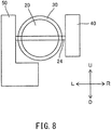
- FIG. 5 is a sectional view taken along line V-V in FIG. 2 .
- the electric motor 54 is not shown.
- the electric-powered valve drive mechanism 50 rotates the single throttle valve 20 about the rotation center axis 20C when supplied with electric power.
- the electric-powered valve drive mechanism 50 includes a deceleration mechanism 52, an electric motor 54, and a valve drive mechanism housing case 56.
- the deceleration mechanism 52 transmits the output of the electric motor 54 to the single throttle valve 20.
- the deceleration mechanism 52 is mechanically connected to the single throttle valve 20.
- the electric motor 54 is mechanically connected to the deceleration mechanism 52.
- the electric motor 54 rotates the single throttle valve 20 about the rotation center axis 20C through the deceleration mechanism 52 when supplied with electric power.
- the deceleration mechanism 52 is a deceleration gear train comprising a plurality of gears.
- the rotation center axes of each of the plurality of gears constituting the deceleration gear train are parallel to each other.
- the rotation center axis of each of the plurality of gears constituting the deceleration gear train extends in the left-right direction LR. In other words, the rotation center axis of each of the plurality of gears constituting the deceleration gear train is parallel to the rotation center axis 20C of the single throttle valve 20.
- the deceleration mechanism 52 includes an output gear 521, a transmission gear 522, and an output gear 523. These will be described below.
- the output gear 521 is fixed to the output shaft of the electric motor 54.
- the output gear 521 rotates together with the output shaft of the electric motor 54 when the electric motor 54 is supplied with electric power.
- the rotation center axis of the output gear 521 is parallel to the rotation center axis 20C of the single throttle valve 20.
- the transmission gear 522 includes a large gear 5221 and a small gear 5222.
- the large gear 5221 and the small gear 5222 are arranged coaxially.
- the transmission gear 522 is arranged rotatably with respect to a shaft 53 supported by the valve drive mechanism housing case 56.
- the rotation center axis of the transmission gear 522 is parallel to the rotation center axis 20C of the single throttle valve 20.
- the large gear 5221 of the transmission gear 522 is engaged with the output gear 521. Accordingly, the rotation of the output gear 521 is transmitted to the transmission gear 522.
- the output gear 523 is fixed to the single throttle valve 20. Specifically, the output gear 523 is fixed to the single throttle valve 20 via the valve rotation support shaft 24. The output gear 523 is fixed to the left end portion of the valve rotation support shaft 24 to which the single throttle valve 20 is fixed. In other words, the rotation center axis of the output gear 523 matches the rotation center axis 20C of the single throttle valve 20. The output gear 523 is engaged with the small gear 5222 of the transmission gear 522. Accordingly, the rotation of the transmission gear 522 is transmitted to the output gear 523. As a result, the single throttle valve 20 to which the output gear 523 is fixed rotates about the rotation center axis 20C.
- the output gear 523 is provided with teeth engaging with the teeth of the small gear 5222 of the transmission gear 522 over a range necessary for the movement of the single throttle valve 20 between the fully closed position P1 and the fully opened position P2. In other words, the teeth of the output gear 523 are not provided over the entire circumference in the circumferential direction around the rotation center axis of the output gear 523.
- the output gear 523 when viewed in the left direction L or the right direction R, overlaps the entire intake air temperature sensor hole 342.
- the output gear 523 may not overlap the entire intake air temperature sensor hole 342 when viewed in the left direction L or the right direction R over the entire rotation range of the output gear 523.
- the output gear 523 may overlap at least a part of the intake air temperature sensor hole 342 when viewed in the left direction L or the right direction R in at least a part of the rotation range of the output gear 523.
- the output gear 523 may not overlap the intake air temperature sensor hole 342 when viewed in the left direction L or the right direction R.
- the output gear 523 when viewed in the left direction L or the right direction R, overlaps a part of the intake air pressure sensor hole 341.
- the output gear 523 may not overlap a part of the intake pressure sensor hole 341 when viewed in the left direction L or the right direction R over the entire rotation range of the output gear 523.
- the output gear 523 may overlap at least a part of the intake pressure sensor hole 341 when viewed in the left direction L or the right direction R in at least a part of the rotation range of the output gear 523.
- the output gear 523 may not overlap the intake pressure sensor hole 341 when viewed in the left direction L or the right direction R.
- the rotation center axis of the output gear 521 (rotation center axis of the output shaft of the electric motor 54), the rotation center axis of the transmission gear 522, and the rotation center axis of the output gear 523 (rotation center axis 20C of the single throttle valve 20) are arranged in the up-down direction UD when viewed in the left direction L or the right direction R.
- the rotation center axis of the output gear 521 (rotation center axis of the output shaft of the electric motor 54), the rotation center axis of the transmission gear 522, and the rotation center axis of the output gear 523 (rotation center axis 20C of the single throttle valve 20) are positioned on a straight line extending in the up-down direction UD (above-described up-down reference line 32L2) when viewed in the left direction L or the right direction R.
- the valve drive mechanism housing case 56 houses the deceleration mechanism 52 and the single electric motor 54.
- the valve drive mechanism housing case 56 overlaps the intake state detection sensor circuit board housing case 46 when viewed in the left direction L or the right direction R.
- the valve drive mechanism housing case 56 is larger than the intake state detection sensor circuit board housing case 46 when viewed in the left direction L or the right direction R.
- the intake state detection sensor circuit board housing case 46 is smaller than the valve drive mechanism housing case 56 when viewed in the left direction L or the right direction R.
- the entire intake state detection sensor circuit board housing case 46 overlaps the valve drive mechanism housing case 56.
- the valve drive mechanism housing case 56 includes a housing case body 561 and a housing case cover 562. These will be described below.
- the housing case body 561 is formed integrally with respect to the single throttle body 30.
- the housing case body 561 is opened toward the left direction L.
- the housing case cover 562 is attached to the housing case body 561.
- the housing case cover 562 covers the opening of the housing case body 561. Accordingly, a housing space for housing the deceleration mechanism 52 and the electric motor 54 is formed between the housing case body 561 and the housing case cover 562.
- the valve drive mechanism housing case 56 houses the deceleration mechanism 52 and the electric motor 54.
- valve drive mechanism housing case 56 houses the deceleration mechanism 52 and the electric motor 54 in such a way described above, the deceleration mechanism 52 is arranged to the left of the single throttle valve 20 in the left-right direction LR.
- the electric motor 54 is positioned below the single airflow passage 32 formed within the single throttle body 30 in the up-down direction UD.
- the housing case cover 562 has a projection 5621 positioned on the rotation center axis of the output gear 523.
- the IC 571 constituting the throttle opening sensor 57 for detecting the opening of the single throttle valve 20 is arranged on the projection 5621.
- One example of the IC 571 is a Hall element.
- the IC 571 detects the change in the magnetic field formed by the magnet 572 constituting the throttle opening sensor 57 that is caused by the rotation of the output gear 523, i.e., the rotation of the single throttle valve 20.
- the magnet 572 is rotatably arranged with the output gear 523 and is positioned around the projection 5621.
- the throttle opening sensor 57 is arranged to the left of the single throttle valve 20
- the throttle opening sensor is arranged distributedly to the left and right of the single throttle valve 20 as is clear from the above description.
- the deceleration mechanism 52 is arranged to the left of the single throttle valve 20 in the left-right direction LR, and the intake state detection sensor circuit board 44 is arranged to the right of the single throttle valve 20 in the left-right direction LR.
- the intake state detection board unit 40 and the electric-powered valve drive mechanism 50 which are the plurality of electronic components, are not arranged collectively to the left or right of the single throttle valve 20, but are arranged distributedly to the left and right of the single throttle valve 20. This allows to reduce the size of the throttle body assembly for a single combustion chamber 10, particularly the size in at least one of the left-right direction LR and the front-back direction FB. They will be described specifically as follows.
- FIG. 6 is a schematic view showing a case where the electric-powered valve drive mechanism 50 and the intake state detection board unit 40 are arranged collectively to the right of the single throttle valve 20, and the electric-powered valve drive mechanism 50 is arranged closer to the single throttle valve 20 than the intake state detection board unit 40.
- FIG. 6 is a schematic view showing a case where the electric-powered valve drive mechanism 50 and the intake state detection board unit 40 are arranged collectively to the right of the single throttle valve 20, and the electric-powered valve drive mechanism 50 is arranged closer to the single throttle valve 20 than the intake state detection board unit 40.
- FIG. 7 is a schematic view showing a case where the electric-powered valve drive mechanism 50 and the intake state detection board unit 40 are arranged collectively to the right of the single throttle valve 20, and the intake state detection board unit 40 is arranged closer to the single throttle valve 20 than the electric-powered valve drive mechanism 50.
- the electric-powered valve drive mechanism 50 is arranged closer to the single throttle valve 20 than the intake state detection board unit 40, it is necessary to form the sensor hole (intake pressure sensor hole 341 and intake temperature sensor hole 342) so as to avoid the deceleration mechanism 52 provided in the electric-powered valve drive mechanism 50. Accordingly, the length of the throttle body assembly for a single combustion chamber is increased in the direction in which the single airflow passage 32 formed by the single throttle body 30 extends (the front-back direction FB).
- the deceleration mechanism 52 is a member that is driven by the transmission of the driving force by the electric motor 54, i.e., a movable member.
- the intake state detection sensor (the intake pressure sensor 421 and the intake temperature sensor 422) and the intake state detection sensor circuit board 44 provided in the intake state detection board unit 40 are members that are not movable, i.e., immovable members, since the driving force is not transmitted to them.
- Such movable and immovable members are required to be arranged away from each other to avoid interference between them.
- each of the electric-powered valve drive mechanism 50 and the intake state detection board unit 40 is arranged collectively on the right side of the single throttle valve 20, the electric-powered valve drive mechanism 50 and the intake state detection board unit 40 are required to be away from each other in the left-right direction LR in order to avoid interference between the deceleration mechanism 52 provided in the electric-powered valve drive mechanism 50, the intake state detection sensor (the intake pressure sensor 421 and the intake temperature sensor 422) provided in the intake state detection board unit, and the intake state detection sensor circuit board 44. This increases the length of the throttle body assembly for a single combustion chamber in the left-right direction.
- the valve rotation support shaft 24 rotatably supporting the single throttle valve 20 is arranged through the intake state detection sensor circuit board 44 of the intake state detection board unit 40.
- a through hole through which the valve rotation support shaft 24 is inserted is formed on the intake state detection board unit 44. Forming the through hole reduces the area of the intake state detection sensor circuit board 44.
- the intake state detection sensor circuit board 44 could extend in the front-back direction FB. In this case, the length in the front-back direction FB of the throttle body assembly for a single combustion chamber 10 is increased.
- the intake state detection board unit 40 and the electric-powered valve drive mechanism 50 which are a plurality of electronic components, are not arranged collectively to the left or the right of the single throttle valve 20 as shown in FIG. 8 , but are arranged distributedly to the left and the right of the single throttle valve 20.
- Distributedly arranging the intake state detection board unit 40 and the electric-powered valve drive mechanism 50, which are a plurality of electronic components, to the left and the right of the single throttle valve 20, instead of collectively arranging them to the left or the right of the single throttle valve 20 provides improved flexibility in designing the intake state detection board unit 40 and the electric-powered valve drive mechanism 50 in the left-right direction LR.
- the side surface of the intake state detection board unit 40 close to the single throttle valve 20 has improved flexibility in designing.
- the intake state detection board unit 40 can be arranged close to the single throttle valve 20 in the left-right direction LR. In other words, the size of the throttle body assembly for a single combustion chamber 10 in the left-right direction LR can be reduced.
- distributedly arranging the intake state detection board unit 40 and the electric-powered valve drive mechanism 50, which are a plurality of electronic components, to the left and the right of the single throttle valve 20, instead of collectively arranging them to the left or the right of the single throttle valve 20 eliminates the need for forming the sensor hole (the intake pressure sensor hole 341 and the intake temperature sensor hole 342) so as to avoid the deceleration mechanism 52 provided in the electric-powered valve drive mechanism 50.
- the intake air pressure sensor hole 341 overlaps each of the intake air state detection sensor circuit board housing case 46 and the valve drive mechanism housing case 56, and the intake air temperature sensor hole 342 overlaps each of the intake air state detection sensor circuit board 44 and the valve drive mechanism housing case 56.
- the size of the throttle body assembly for a single combustion chamber 10 in the front-back direction FB can be reduced.
- distributedly arranging the intake state detection board unit 40 and the electric-powered valve drive mechanism 50, which are a plurality of electronic components, to the left and the right of the single throttle valve 20 instead of collectively arranging them to the left or the right of the single throttle valve 20 eliminates the need for forming a clearance (a clearance in the left-right direction LR) that is for avoiding interference between the deceleration mechanism 52, which is a movable member of the electric-powered valve drive mechanism 50, and the intake state detection sensor circuit board 44 and the intake state detection sensor (the intake pressure sensor 421 and the intake temperature sensor 422) of the intake state detection board unit 40, which are immovable members.
- the size of the throttle body assembly for a single combustion chamber 10 in the left-right LR can be reduced.
- the single airflow passage 32 has a circular cross-section. This can reduce the size of the single throttle valve 20 in the left-right direction LR arranged in the single airflow passage 32 as compared with a laterally (i.e., the left-right direction LR is longer than the up-down direction UD) elliptical cross-section of the single airflow passage 32. As a result, the size of the throttle body assembly for a single combustion chamber 10 in the left-right direction LR can be reduced.
- the intake pressure sensor hole 341 when viewed in the left direction L or the right direction R, overlaps the intake state detection sensor circuit board housing case 46. Accordingly, the intake pressure sensor hole 341 can be brought closer to the rotation center axis 20C of the single throttle valve 20 in the front-back direction FB. Thus, the size of the throttle body assembly for a single combustion chamber 10 in the front-back direction FB can be reduced.
- the intake state detection sensor circuit board housing case 46 is smaller than the valve drive mechanism housing case 56 when viewed in the left direction L or the right direction R. This, for example, allows to suppress the interference of the intake state detection sensor circuit board housing case 46 with other members when the throttle body assembly for a single combustion chamber 10 is mounted on a straddled vehicle.
- each of the intake air pressure sensor hole 341 and the intake air temperature sensor hole 342 overlaps the range A1 in which the single throttle valve 20 is rotatable when the single throttle valve 20 rotates about the rotation center axis 20 when viewed in the left direction L or the right direction R.
- the intake pressure sensor hole 341 and the intake temperature sensor hole 342 can be brought closer to the rotation center axis 20C of the single throttle valve 20 in the front-back direction FB. This allows the size of the throttle body assembly for a single combustion chamber 10 in the front-back direction FB to be reduced.
- FIG. 9 is a schematic diagram showing the positional relationship among the single throttle valve 20, the intake state detecting board unit 40, and the electric-powered valve driving mechanism 50 when the intake state detecting board unit 40 and the electric-powered valve driving mechanism 50 are arranged distributedly to the left and the right of the single throttle valve 20 as well as the positional relationship between the connector 49 of the intake state detecting board unit 40 and the connector 58 of the electric-powered valve driving mechanism 50. While not shown in FIG.
- the intake state detection sensor circuit board 44 of the intake state detection circuit board unit 40 is arranged to the right of the single throttle valve 20 in the left-right direction LR, and the deceleration mechanism 52 of the electric-powered valve drive mechanism 50 is arranged to the left of the single throttle valve 20 in the left-right direction LR.
- the intake state detection board unit 40 further includes a connector 49 as a sensor connector.
- a sensor wiring (not shown) for operating the intake state detection sensor (the intake pressure sensor 421 and the intake temperature sensor 422) is connected to the connector 49.
- the connector 49 is provided, for example, in the intake state detection sensor circuit board housing case 46.
- the connector 49 is arranged so as to allow the sensor wiring to be inserted and connected in the back direction B.
- the connector 49 is formed to open in the front direction F.
- the intake state detection sensor circuit board 44 is arranged to the right of the single throttle valve 20 in the left-right direction LR. Accordingly, the connector 49 is arranged to the right of the single throttle valve 20 in the left-right direction LR.
- the electric-powered valve drive mechanism 50 further includes a connector 58 as a motor connector.
- a motor wire for driving the electric motor 54 (not shown) is connected to a connector 58.
- the connector 58 is provided, for example, in the valve drive mechanism housing case 56.
- the connector 58 is arranged so as to allow the motor wiring to be inserted and connected in the front direction F. This means that the connector 58 is formed so as to open in the back direction B. In other words, the connector 58 is formed so as to open in a different direction from the connector 49. The connector 58, however, may be formed so as to open in the same direction as the connector 49.
- the deceleration mechanism 52 of the electric-powered valve drive mechanism 50 is arranged to the left of the single throttle valve 20 in the left-right direction LR. Accordingly, the connector 58 is arranged to the left of the single throttle valve 20 in the left-right direction LR.
- Such the throttle body assembly for a single combustion chamber 10 allows the connectors 58 and 49 to be arranged distributedly to the left and right of the single throttle valve 20. This can result in a compact arrangement of the motor wiring connected to the connector 58 (not shown) and the sensor wiring connected to the connector 49 (not shown). The reasons are as follows.
- the embodiment where the connector 58 and the connector 49 are arranged distributedly as described above reduces the number of connector pins of each of the connector 58 and the connector 49 compared to one where the connector 58 and the connector 49 are arranged collectively. Accordingly, the wiring connected to each of the connector 58 and the connector 49 becomes thin. When the wiring becomes thin, it becomes easy to be bent. This allows to arrange compactly.
- the motor connector may be arranged to the right of the single throttle valve 20 in the left-right direction LR and the sensor connector (connector 49) may be arranged to the left of the single throttle valve 20 in the left-right direction LR.
- Embodiments and modifications that are at least described or illustrated herein are for ease of understanding of the present disclosure and are not intended to limit the spirit of the present disclosure.
- the embodiments and modifications described above may be modified and improved without departing from the spirit thereof.
- the intake air temperature sensor hole 342 overlaps each of the intake air state detection sensor circuit board 44 and the valve drive mechanism housing case 56 when viewed in the left direction L or the right direction R
- the intake air pressure sensor hole 341 may overlap each of the intake air state detection sensor circuit board 44 and the valve drive mechanism housing case 56.
- each of the intake pressure sensor hole 341 and the intake temperature sensor hole 342 may overlap each of the intake state detection sensor circuit board 44 and the valve drive mechanism housing case 56 when viewed in the left direction L or the right direction R.
- the deceleration mechanism 52 is arranged to the left of the single throttle valve 20 in the left-right direction LR and the intake state detection sensor circuit board 44 is arranged to the right of the single throttle valve 20 in the left-right direction LR
- the deceleration mechanism 52 may be arranged to the right of the single throttle valve 20 in the left-right direction LR and the intake state detection sensor circuit board 44 may be arranged to the left of the single throttle valve 20 in the left-right direction LR.
- each of the intake pressure sensor hole 341 and the intake temperature sensor hole 342 is arranged to the left of the single throttle valve 20 in the left-right direction LR.
- the intake temperature sensor hole 342 overlaps each of the intake state detection sensor circuit board 44 and the valve drive mechanism housing case 56.
- the intake pressure sensor hole 341 may overlap each of the intake state detection sensor circuit board 44 and the valve drive mechanism housing case 56.
- each of the intake pressure sensor hole 341 and the intake temperature sensor hole 342 may overlap each of the intake state detection sensor circuit board 44 and the valve drive mechanism housing case 56.
- the positional relationship between the intake air pressure sensor 421 and the intake air temperature sensor 422 is not limited to one described in the above embodiment.
- the intake air pressure sensor 421 when viewed in the left direction L or the right direction R, the intake air pressure sensor 421 may be positioned on the front-back reference line 32L1, and the intake air temperature sensor 422 may not be positioned on the front-back reference line 32L1.
- each of the intake air pressure sensor 421 and the intake air temperature sensor 422 may be positioned on the front-back reference line 32L1 when viewed in the left direction L or the right direction R.
- the intake pressure sensor 421 and the intake temperature sensor 422 may not be positioned on the front-back reference line 32L1 when viewed in the left direction L or the right direction R.
- each of the intake pressure sensor 421 and the intake temperature sensor 422 may be positioned above the front-back reference line 32L1 or below the front-back reference line 32L1 when viewed in the left direction L or the right direction R.
- one of the intake pressure sensor 421 and the intake temperature sensor 422 may be positioned above the front-back reference line 32L1 and the other of the intake pressure sensor 421 and the intake temperature sensor 422 may be positioned below the front-back reference line 32L1 when viewed in the left direction L or the right direction R.
- the intake pressure sensor 421 may be positioned upstream of the up-down reference line 32L2.
- the intake air temperature sensor 422 may be positioned downstream of the up-down reference line 32L2.
- each of the intake pressure sensor 421 and the intake temperature sensor 422 may be positioned upstream of the up-down reference line 32L2.
- each of the intake pressure sensor 421 and the intake temperature sensor 422 may be positioned downstream of the up-down reference line 32L2.
- the present teaching can of course be applied to a case where one intake state detection sensor is provided or a case where three or more intake state detection sensors are provided.
- the said intake state detection sensor may be an intake pressure sensor 421 or an intake temperature sensor 422.
- the sensor holes may not overlap the rotation range A1 of the single throttle valve 20 when viewed in the left direction L or the right direction R.
- the intake pressure sensor hole 341 and the intake temperature sensor hole 342 may be formed downstream of the up-down reference line 32L2 and may not overlap the rotation range A1 of the single throttle valve 20 when viewed in the left direction L or the right direction R.
- the electric motor 54 is positioned below the single airflow passage 32 formed inside the single throttle body 30 when viewed in the front direction F or the back direction B, the electric motor 54 may be positioned above the single airflow passage 32 formed within the single throttle body 30 when viewed in the front direction F or the back direction B.
- each of the intake air pressure sensor hole 341 and the intake air temperature sensor hole 342 overlaps the intake air state detection sensor circuit board housing case 46 when viewed in the left direction L or the right direction R
- at least one of the intake air pressure sensor hole 341 and the intake air temperature sensor hole 342 may not overlap the intake air state detection sensor circuit board housing case 46 when viewed in the left direction L or the right direction R.
- the entire intake state detection sensor circuit board housing case 46 overlaps the valve drive mechanism housing case 56 when viewed in the left direction L or the right direction R, a part of the intake state detection sensor circuit board housing case 46 may project from the valve drive mechanism housing case 56 when viewed in the left direction L or the right direction R.
- each of the intake air pressure sensor 421 and the intake air temperature sensor 422 overlaps the range A1 in which the single throttle valve 20 is rotatable at least in part, for example, each of the intake air pressure sensor 421 and the intake air temperature sensor 422 does not overlap the range A1 when viewed in the left direction L or the right direction R.
- either one of the intake pressure sensor 421 or the intake temperature sensor 422 may overlap the range A1.
- the throttle opening sensors are arranged distributedly to the left and the right of the single throttle valve 20 in the above embodiment, the throttle opening sensors may be arranged collectively to either the left or the right of the single throttle valve 20.
- two ICs constituting the throttle opening sensor are arranged collectively.
- a common magnet is arranged around the two ICs. Comparing the outputs from the two ICs enables to detect which one of the two ICs has failures.
Landscapes
- Engineering & Computer Science (AREA)
- Chemical & Material Sciences (AREA)
- Combustion & Propulsion (AREA)
- Mechanical Engineering (AREA)
- General Engineering & Computer Science (AREA)
- Control Of Throttle Valves Provided In The Intake System Or In The Exhaust System (AREA)
- Combined Controls Of Internal Combustion Engines (AREA)
Abstract
Description
- The present teaching relates to a throttle body assembly for a single combustion chamber comprising a single airflow passage connected to a single combustion chamber and a single throttle valve arranged in the single airflow passage.
- A throttle body assembly for a single combustion chamber comprising a single airflow passage connected to the single combustion chamber is known as one of throttle body assemblies mounted on a straddled vehicle. Such a throttle body assembly for a single combustion chamber comprises a single throttle body and a single throttle valve. The single throttle body forms a single airflow passage connected to the single combustion chamber. The single throttle valve is arranged in the single airflow passage to regulate an amount of air taken into the single combustion chamber.
- A straddled vehicle has a compact body compared with a four-wheeled vehicle. Accordingly, a throttle body assembly mounted on a straddled vehicle is arranged near an engine compared with a throttle body assembly mounted on a four-wheeled vehicle. In other words, the throttle body assembly for a single combustion chamber described above is arranged near an engine. This requires to reduce the size of a throttle body assembly for a single combustion chamber to avoid interference with such as an engine body (for example, a cylinder) and an air cleaner.
- A throttle body assembly for a single combustion chamber comprising an intake state detection board unit for detecting the state of air flowing through a single airflow passage is also known. The intake state detection board unit includes an intake state detection sensor for detecting the state of air flowing through a single airflow passage and a board to which the intake state detection sensor is connected. The intake state detection sensor is, for example, an intake air pressure sensor for detecting the pressure of air flowing through a single airflow passage, or an intake air temperature sensor for detecting the temperature of air flowing through a single airflow passage.
- When an intake state detection board unit has a plurality of intake state detection sensors, the plurality of intake state detection sensors is connected to a board directly or through wiring to be collectively arranged on or in the vicinity of the board. The plurality of intake state detection sensors includes, for example, an intake pressure sensor for detecting the pressure of air flowing through a single airflow passage and an intake air temperature sensor for detecting the temperature of air flowing through a single airflow passage.
- In such throttle body assemblies for a single combustion chamber comprising an intake state detection board unit, arranging collectively a plurality of intake state detection sensors on or in the vicinity of a board meets requirements for a throttle body assembly for a single combustion chamber (i.e. reducing the size of a throttle body assembly for a single combustion chamber). In other words, arranging collectively a plurality of electronic components achieves to reduce the size of a throttle body assembly for a single combustion chamber.
- Such a technical idea of a person skilled in the art is disclosed in, for example,
WO2005/038223 ,WO2004/074661 ,Japanese Patent Publication No.6313405 Japanese Patent Application Publication No.2014- 181646 Japanese Patent Application Publication No.2007-118868 - An intake device disclosed in
WO2005/038223 comprises a throttle body and a sensor unit. The sensor unit is mounted on the throttle body. The sensor unit comprises an intake air temperature sensor and a pressure sensor, which are a plurality of electronic components. The sensor unit further comprises a board on which the pressure sensor is mounted. - The throttle device disclosed in
WO2004/074661 comprises a sensor module unit. The sensor module unit is constituted by integrally mounting a plurality of sensors, which is a plurality of electronic components required for fuel supply control and intake air flow rate control in an internal combustion engine. The plurality of sensors includes an intake air temperature sensor and an intake air pressure sensor. In addition, the sensor module unit includes a circuit board. A lead wire from the intake temperature sensor as well as an intake pressure sensor are attached to the circuit board. - A throttle valve device disclosed in
Japanese Patent Publication No. 6313405 - An intake device disclosed in Unexamined
Japanese Patent Application Publication No. 2014-181646 - Unexamined
Japanese Patent Application Publication No. 2007-118868 -
- [Patent Document 1]
WO2005/038223 - [Patent Document 2]
WO2004/074661 - [Patent Document 3]
Japanese Patent No.6313405 - [Patent Document 4] Unexamined
Japanese Patent Application Publication No.2014-181646 - [Patent Document 5] Unexamined
Japanese Patent Application Publication No.2007-118868 - The throttle body assembly for a single combustion chamber comprising the intake state detection board unit disclosed in the above publications comprises a mechanism that drives a single throttle valve through a wire. Such a wire-type valve drive mechanism could be changed to an electric-powered valve drive mechanism. The electric-powered valve drive mechanism includes an electric motor driven by the supply of electric power, and a deceleration mechanism for transmitting the driving force of the electric motor to a throttle valve.
- The electric-powered valve drive mechanism includes an electric motor driven by power supply, and therefore is an electronic component. The intake state detection board unit includes an intake state detection sensor, and therefore is an electronic component.
- Consequently, a person skilled in the art would collectively arrange the electric-powered valve drive mechanism and the intake state detection board unit, which are both a plurality of electronic components, in accordance with the above-described technical idea, i.e., the technical idea of collectively arranging a plurality of electronic components. However, it has found difficult for collectively arranging an electric-powered valve drive mechanism and an intake state detection board unit, which are a plurality of electronic components, to reduce the size of a throttle body assembly for a single combustion chamber.
- It is an object of the present teaching to provide a throttle body assembly for a single combustion chamber comprising a single throttle body forming a single airflow passage connected to a single combustion chamber, a single throttle valve arranged in the single airflow passage for regulating an amount of air taken into the single combustion chamber, an electric-powered valve drive mechanism for driving the single throttle valve, and an intake state detection board unit for detecting the state of air flowing through the single airflow passage, wherein the size of the throttle body assembly for a single combustion chamber can be reduced.
- In a throttle body assembly for a single combustion chamber comprising a single throttle body that forms a single airflow passage connected to a single combustion chamber, the single throttle valve arranged in the single airflow passage and regulates an amount of air taken into the single combustion chamber, a valve drive mechanism for driving the single throttle valve, and an intake state detection board unit for detecting the state of air flowing through the single airflow passage, the present inventors have considered changing a wire-type valve drive mechanism to an electric-powered valve drive mechanism.
- The electric-powered valve drive mechanism includes an electric motor driven by the supply of electric power and a deceleration mechanism for transmitting the driving force of the electric motor to the throttle valve. In other words, the electric-powered valve drive mechanism is an electronic component.
- In addition, the intake state detection board unit for detecting the state of the air flowing through the single airflow passage includes an intake state detection sensor for detecting the state of the air flowing through the single airflow passage. The intake state detection sensor is an electronic component. In other words, the intake state detection board unit is also an electronic component.
- Accordingly, when a wire-type valve drive mechanism is changed to electric-powered valve drive mechanism in a throttle body assembly for a single combustion chamber comprising a single throttle body forming a single airflow passage connected to a single combustion chamber, a single throttle valve arranged in the single airflow passage for regulating an amount of air taken into the single combustion chamber, a valve drive mechanism for driving the single throttle valve, and an intake state detection board unit for detecting the state of air flowing through the single airflow passage, the throttle body assembly for a single combustion chamber includes a plurality of electric-powered devices.
- Thus, a person skilled in the art would collectively arrange an electric-powered valve drive mechanism and an intake state detection board unit, which are a plurality of electronic components, in accordance with the technical idea of collectively arranging a plurality of electronic components. Accordingly, the present inventors also have considered collectively arranging an electric-powered valve drive mechanism and an intake state detection board unit, which are a plurality of electronic components, in accordance with such the technical idea. This is specifically described as follows.
- A direction in which the rotation center axis of a single throttle valve extends is referred to as the left-right direction, and embodiments have been considered in which an electric-powered valve drive mechanism and an intake state detection board unit are collectively arranged to the left or the right of a single throttle valve. Specifically, these embodiments are ones in which (1) an electric-powered valve drive mechanism is arranged closer to a single throttle valve than an intake state detection board unit, and in which (2) an intake state detection board unit is arranged closer to a single throttle valve than an electric-powered valve drive mechanism.
- The intake state detection sensor requires to form a sensor hole that communicates with a single airflow passage formed by a single throttle body in the single throttle body to detect the state of the air flowing through a single airflow passage. The present inventors have considered above-described embodiments (1) and (2) while focusing on the positional relationships between such the sensor hole, the electric-powered valve drive mechanism, and the intake state detection board unit. As a result, they have obtained following findings.
- In the embodiment (1), the sensor hole needs to avoid the deceleration mechanism provided in the electric-powered valve drive mechanism to be formed since the electric-powered valve drive mechanism is arranged closer to the single throttle valve than the intake state detection board unit. Thus, the length of the throttle body assembly for a single combustion chamber is increased in the front-back direction, which is the direction in which a single airflow passage formed by a single throttle body extends.
- Further, the deceleration mechanism is a member driven by the transmitted driving force of the electric motor, i.e., a movable member. On the other hand, no driving forces are transmitted to the intake state detection sensor and the board provided in the intake state detection board unit, and thus they are members that do not move, i.e., immovable members. Such movable and immovable members are required to be arranged away from each other to avoid interference.
- In the embodiment (1), since the electric-powered valve drive mechanism and the intake state detection board unit are collectively arranged to the left or the right of a single throttle valve, the electric-powered valve drive mechanism and the intake state detection board unit are required to be away from each other in the left-right direction in order to avoid interference between the deceleration mechanism provided in the electric-powered valve drive mechanism, and the board and the intake state detection sensor provided in the intake state detection board unit. This increases the length of the throttle body assembly for a single combustion chamber in the left-right direction.
- In the embodiment (2), the length of the throttle body assembly for a single combustion chamber in the left-right direction is increased for the same reason as described above.
- Still in the embodiment (2), since the intake state detection board unit is arranged closer to the single throttle valve than the electric-powered valve drive mechanism, the valve rotation support shaft rotatably supporting the throttle valve is arranged through the board of the intake state detection board unit. In other words, a through hole for inserting the valve rotation support shaft is formed on the board. The formation of the through holes reduces the area of the board. In order to prevent reducing the area of the board, for example, the board increases its length in the front-back direction. In this case, the length of the throttle body assembly for a single combustion chamber in the front-back direction is increased.
- Accordingly, it has been found that collectively arranging the electric-powered valve drive mechanism and the intake state detection board unit in accordance with the technical idea of collectively arranging a plurality of electronic components results in increasing the size of the throttle body assembly for a single combustion chamber, and it has been found difficult to reduce the size of the throttle body assembly for a single combustion chamber.
- Consequently, the present inventors have considered reducing the size of the throttle body assembly for a single combustion chamber from other perspectives than the one of collectively arranging the electric-powered valve drive mechanism and the intake state detection board unit, which are a plurality of electronic components, in accordance with the technical idea of collectively arranging a plurality of electronic components. Specifically, they have considered focusing on the size of a single throttle valve provided in the throttle body assembly for a single combustion chamber. As a result, they have obtained following findings.
- A single throttle valve included in the single throttle body assembly for a single combustion chamber is naturally small. Accordingly, the deceleration mechanism of the electric-powered valve drive mechanism is larger than the throttle valve in at least one of the front-back direction of the throttle body assembly for a single combustion chamber, i.e., the direction in which the single airflow passage extends, and the up-down direction of the throttle body assembly for a single combustion chamber, i.e., both of the direction perpendicular to the direction in which the single airflow passage extends and the direction perpendicular to the direction in which the rotation center axis of the single throttle valve extends. In other words, the throttle valve is smaller than the deceleration mechanism of the electric-powered valve drive mechanism in at least one of the front-back and up-down directions of the throttle body assembly for a single combustion chamber. Similarly, the intake state detection board unit and the board provided in the intake state detection board unit also can be larger than the intake state detection board unit in at least one of the front-back direction and the up-down direction of the throttle body assembly for a single combustion chamber.
- Based on such findings, the present inventors have further considered. As a result, they have found that the size of the throttle body assembly for a single combustion chamber in the left-right direction can be reduced not by collectively arranging the intake state detection board unit and the electric-powered valve drive mechanism, which are a plurality of electronic components, to the left or the right of the single throttle valve, but by distributedly arranging them to the left and the right of the single throttle valve. This is described specifically as follows.
- Distributedly arranging the intake state detection board units and the electric-powered valve drive mechanism, which are a plurality of electronic components, to the left and the right of the single throttle valve instead of collectively arranging them to the left or the right of the single throttle valve provides improved flexibility in designing the intake state detection board units and the electric-powered valve drive mechanism in the left-right direction. For example, the side surface of the intake state detection board unit that is close to the single throttle valve has improved flexibility in designing when viewed in the front-back direction. As a result, the intake state detection board unit can be arranged close to the single throttle valve in the left-right direction. In other words, the size of the throttle body assembly for a single combustion chamber in the left-right direction can be reduced.
- Such findings were first obtained by distributedly arranging the intake state detection board unit and the electric-powered valve drive mechanism, which are a plurality of electronic components, to the left and to the right of a single throttle valve instead of collectively arranging them to the left or the right of a single throttle valve based on the fact that 'a single throttle is small', which is characteristic of a throttle body assembly for a single combustion chamber.
- Further, distributedly arranging the intake state detection board unit and the electric-powered valve drive mechanism, which are a plurality of electronic components, to the left and the right of the single throttle valve instead of collectively arranging them to the left or the right of the single throttle valve eliminates the need for forming the sensor hole so as to avoid the deceleration mechanism provided in the electric-powered valve drive mechanism. Thus, the sensor hole can be formed at any position. In other words, the sensor holes have improved flexibility in designing. As a result, the size of the throttle body assembly for a single combustion chamber in the front-back direction can be reduced.
- In addition, distributedly arranging the intake state detection board unit and the electric-powered valve drive mechanism, which is a plurality of electronic components, to the left and the right of the single throttle valve instead of collectively arranging them to the left or the right of the single throttle valve eliminates the need for forming a clearance (a clearance in the left-right direction) that is for avoiding interference between the deceleration mechanism, which is a movable member provided in the electric-powered valve drive mechanism, and the board and the intake state detection sensor, which are immovable members provided in the intake state detection board unit. As a result, the size of the throttle body assembly for a single combustion chamber in the left-right direction can be reduced.
- As described above, the size, in particular, at least one in the left-right and front-back direction, of the throttle body assembly for a single combustion chamber can be reduced by distributedly arranging the intake state detection board unit and the electric-powered valve drive mechanism, which are a plurality of electronic components, to the left and the right of the single throttle valve, instead of collectively arranging them to the left or the right of the single throttle valve. The present teaching has been made based on such findings.
- A throttle body assembly for a single combustion chamber according to one embodiment of the present teaching comprises a single throttle valve and a single throttle body. The single throttle valve regulates an amount of air taken into a single combustion chamber and is rotatable about its rotation center axis. The single throttle body is connected to the single combustion chamber and forms a single airflow passage in which the single throttle valve is arranged. The throttle body assembly for a single combustion chamber comprises an intake state detection board unit and an electric-powered valve drive mechanism. The intake state detection board unit detects a state of air flowing through the single airflow passage. The electric-powered valve drive mechanism rotates the single throttle valve about the rotation center axis when supplied with electric power. The intake state detection board unit includes one or more intake state detection sensors, an intake state detection sensor circuit board, and an intake state detection sensor circuit board housing case. The intake state detection sensor detects a state of air flowing through the single airflow passage. One or more of the intake state detection sensors are connected to the intake state detection sensor circuit board. The intake state detection sensor circuit board housing case houses the intake state detection sensor circuit board. The electric-powered valve drive mechanism includes a deceleration mechanism, an electric motor, and a valve drive mechanism housing case. The deceleration mechanism is mechanically connected to the single throttle valve. The electric motor is mechanically connected to the deceleration mechanism and rotates the single throttle valve via the deceleration mechanism when supplied with electric power. The valve drive mechanism housing case houses the deceleration mechanism and the electric motor. The deceleration mechanism and the intake state detection sensor circuit board are arranged so as to satisfy either of the following (1) or (2) with respect to the single throttle valve when the rotation center axis of the single throttle valve is arranged parallel to the left-right direction:
- (1) the deceleration mechanism is arranged to the right of the single throttle valve in the left-right direction, and the intake state detection sensor circuit board is arranged to the left of the single throttle valve in the left-right direction.
- (2) the deceleration mechanism is arranged to the left of the single throttle valve in the left-right direction, and the intake state detection sensor circuit board is arranged to the right of the single throttle valve in the left-right direction.
The single throttle body has one or more sensor holes. The sensor holes are for the intake state detection sensors to detect a state of air flowing through the single airflow passage. One or more of the sensor holes are positioned so as to satisfy either of the following (3) or (4): - (3) when the deceleration mechanism and the intake state detection sensor circuit board are arranged so as to satisfy the above (1) with respect to the single throttle valve, one or more of the sensor holes are positioned to the left of the single throttle valve in the left-right direction, and at least one of the sensor holes overlaps each of the intake state detection sensor circuit board housing case and the valve drive mechanism housing case when viewed in the left-right direction.
- (4) when the deceleration mechanism and the intake state detection sensor circuit board are arranged so as to satisfy the above (2) with respect to the single throttle valve, one or more of the sensor holes are positioned to the right of the single throttle valve in the left-right direction, and at least one of the sensor holes overlaps each of the intake state detection sensor circuit board housing case and the valve drive mechanism housing case when viewed in the left-right direction.
- The throttle body assembly for a single combustion chamber described above can reduce the size of the throttle body assembly for a single combustion chamber, particularly, the size in at least one of the left-right and front-back directions since the intake state detection board unit and the electric-powered valve drive mechanism, which are a plurality of electronic components, are not collectively arranged to the left or the right of the single throttle valve, but are distributedly arranged to the left and the right of the single throttle valve.
- In the throttle body assembly for a single combustion chamber described above, the single throttle valve is not particularly limited as long as the single throttle valve regulates an amount of air taken into the single combustion chamber and is rotatable about its rotation center axis. The shape or the like of the single throttle valve is changed as appropriate according to, for example, the shape or the like of the flow passage cross-section of the single airflow passage in which the single throttle valve is arranged. The flow passage cross-section refers to a region within the single throttle body when the single throttle body forming the single airflow passage is cut in a direction orthogonal to a direction in which the single throttle body extends, that is, an opening portion of the single throttle body at the cut surface. The single throttle valve is, for example, arranged in a single airflow passage formed by the single throttle body while it is fixed to a valve rotation support shaft rotatably arranged with respect to the single throttle body. This allows the single throttle valve to be arranged rotatably about the rotation center axis. The rotation of the single throttle valve about its rotation center axis causes the single airflow passage to open or close, which enables the single throttle valve to regulate an amount of air to be taken into the single combustion chamber. The means for fixing the single throttle valve to the valve rotation support shaft is not particularly limited. When the single throttle valve is fixed to the valve rotation support shaft, for example, a screw can be used.
- In the throttle body assembly for a single combustion chamber described above, the single throttle body is not particularly limited as long as it is connected to a single combustion chamber and forms a single airflow passage in which a single throttle valve is arranged. The embodiment in which a single airflow passage is connected to a single combustion chamber is not particularly limited. For example, a single airflow passage may be connected to a single combustion chamber via another airflow passage connected to the said single airflow passage. The flow passage cross-sectional area of a single airflow passage formed within a single throttle body may be constant or varied over the entire length of the single throttle body, i.e., over the entire direction in which the single throttle body extends. The flow passage cross-sectional area refers to an area of a region within the single throttle body when the single throttle body forming the airflow passage is cut in a direction orthogonal to a direction in which the single throttle body extends, that is, an opening area of the single throttle body at the cut surface.
- In the throttle body assembly for a single combustion chamber described above, the intake state detection unit is not particularly limited as long as it detects the state of air flowing through the single airflow passage. The intake state detection sensor is not particularly limited as long as it detects the state of air flowing through the single airflow passage. The state of the air flowing through the single airflow passage may be, for example, the pressure of the air flowing through the single airflow passage or the temperature of the air flowing through the single airflow passage. The intake state detection sensor is not particularly limited as long as it uses a sensor hole formed in the single throttle body to detect the state of air flowing through the single airflow passage formed by the single throttle body. The embodiments in which the intake state detection sensor uses the sensor hole are, for example, one in which the intake state detection sensor detects the state of the air flowing through the airflow passage through the sensor hole, and one in which the intake state detection sensor detects the state of the air flowing through the airflow passage while at least a part of the intake state detection sensor is inserted into the sensor hole. In the latter embodiment, the part of the intake state detection sensor for detecting the state of the air flowing through the airflow passage may be present in the airflow passage.
- In the throttle body assembly for a single combustion chamber described above, it is only required for the sensor hole to be formed to the right or the left of the single throttle valve. The term 'to the right (the left) of the single throttle valve' used here is not limited to 'to the right (the left) of the right end (the left end) of the single throttle valve'. For example, when a single throttle valve has a disc shape and a single throttle valve is in the fully closed position, the term 'to the right (the left) of the single throttle valve' may be 'both to the right (the left) of the center of the single throttle valve in the left-right direction and to the left (the right) of the right end (the left end) of the single throttle valve'.
- In the throttle body assembly for a single combustion chamber described above, the intake state detection sensor circuit board is not particularly limited as long as the intake state detection sensor is connected thereto. The embodiment in which the intake state detection sensor is connected to the intake state detection sensor circuit board is not particularly limited. The intake state detection sensor may be connected directly or indirectly to the intake state detection sensor circuit board. The embodiments in which the intake state detection sensor is directly connected to the intake state detection sensor circuit board include, for example, one in which the intake state detection sensor is mounted on the intake state detection sensor circuit board. The embodiments in which the intake state detection sensor is indirectly connected to the intake state detection sensor circuit board include, for example, one in which the intake state detection sensor is connected to the intake state detection sensor circuit board via a conductive member such as wiring.
- In the throttle body assembly for a single combustion chamber described above, the electric-powered valve drive mechanism is not particularly limited as long as it rotates the single throttle valve about the rotation center axis when supplied with electric power.
- In the throttle body assembly for a single combustion chamber described above, the deceleration mechanism is not particularly limited as long as it is mechanically connected to a single throttle valve. The embodiments in which the deceleration mechanism is mechanically connected to the single throttle valve are not particularly limited as long as they are ones in which the driving force can be transmitted from the deceleration mechanism to the single throttle valve. The deceleration mechanism may be connected directly or indirectly to a single throttle valve. Embodiments in which the deceleration mechanism is indirectly connected to a single throttle valve include, for example, fixing a portion of the deceleration mechanism (for example, any one of a plurality of gears constituting a deceleration mechanism) to a valve rotation support shaft that rotatably supports the single throttle valve. One example of the deceleration mechanism is a deceleration gear train. The deceleration gear train includes, for example, a plurality of gears. Each of the plurality of gears is preferably a spur gear or a helical gear rotatable about an axis parallel to the rotation center axis of a single throttle valve. This allows to reduce the length in the direction in which the rotation center axis of the single throttle valve extends in the deceleration mechanism.
- In the throttle body assembly for a single combustion chamber described above, the electric motor is not particularly limited as long as it is mechanically connected to the deceleration mechanism and rotates a single throttle valve via the deceleration mechanism when supplied with electric power. Embodiments in which the electric motor is mechanically connected to the deceleration mechanism are not particularly limited as long as the driving force can be transmitted from the electric motor to the deceleration mechanism. The electric motor may be directly connected to the deceleration mechanism or may be indirectly connected to the deceleration mechanism. Embodiments in which the electric motor is indirectly connected to the deceleration mechanism include, for example, fixing a portion of the deceleration mechanism (for example, any one of a plurality of gears constituting a deceleration mechanism) to the output shaft of the electric motor.
- In the throttle body assembly for a single combustion chamber described above, the valve drive mechanism housing case is not particularly limited as long as it houses a deceleration mechanism and an electric motor. The valve drive mechanism housing case may include, for example, a portion housing a deceleration mechanism and a portion housing a single electric motor. The valve drive mechanism housing case may have a structure that can be divided in the direction in which the rotation center axis of a single throttle valve extends.
- In the throttle body assembly for a single combustion chamber described above, embodiments in which the sensor holes overlap each of the intake state detection sensor circuit board housing case and the valve drive mechanism housing case when viewed in the left direction or the right direction include not only one in which the entire sensor hole overlaps each of the intake state detection sensor circuit board housing case and the valve drive mechanism housing case when viewed in the left-the right direction, but also one in which a part of the sensor hole overlaps each of the intake state detection sensor circuit board housing case and the valve drive mechanism housing case when viewed in the left direction or the right direction.
- In the throttle body assembly for a single combustion chamber described above, the sensor holes that overlap the intake state detection sensor circuit board housing case when viewed in the left direction or the right direction may or may not overlap the intake state detection sensor circuit board when viewed in the left direction or the right direction
- In the throttle body assembly for a single combustion chamber described above, the single airflow passage may have a circular cross-section.
- Such embodiments can reduce the size of the single throttle valve in the left-right direction arranged in the single airflow passage as compared to the case where the single air flow passage has a laterally elliptical cross-section. Thus, the size of the throttle body assembly for a single combustion chamber in the left-right direction can be reduced.
- It should be noted that the single airflow passage in the throttle body assembly for a single combustion chamber described above is not limited to have a circular cross-section. For example, the single airflow passage may have an elliptical cross-section.
- In the throttle body assembly for a single combustion chamber described above, at least one of the sensor holes may overlap the intake state detection sensor circuit board when viewed in the left direction or the right direction.
- In such an embodiment, the sensor hole can be brought closer to the rotation center axis of the single throttle valve in the front-back direction. Thus, the size of the throttle body assembly for a single combustion chamber in the front-back direction can be reduced.
- In the throttle body assembly for a single combustion chamber described above, the intake state detection sensor circuit board housing case may be smaller than the valve drive mechanism housing case when viewed in the left direction or the right direction.
- In such an embodiment, for example, the interference of the intake state detection sensor circuit board housing case with other members can be reduced while the throttle body assembly for a single combustion chamber is mounted on a straddled vehicle.
- In the throttle body assembly for a single combustion chamber described above, the intake state detection sensor circuit board housing case is not particularly limited as long as it is smaller than the valve drive mechanism housing case when viewed in the left direction or the right direction. The entire intake state detection sensor circuit board housing case may overlap the valve drive mechanism housing case when viewed in the left direction or the right direction. Alternatively, the part of the intake state detection sensor circuit board housing case may project from the valve drive mechanism housing case when viewed in the left direction or the right direction. For example, the front end or the back end of the intake state detection sensor circuit board housing case may be positioned outside the valve drive mechanism housing case when viewed in the left direction or the right direction.
- In the above throttle body assembly for a single combustion chamber described above, the intake state detection board unit may further include a sensor connector. A sensor wiring for operating the intake state detection sensor is connected to the sensor connector. The electric-powered valve drive mechanism may further include a motor connector. A motor wiring for driving the electric motor is connected to the motor connector.
- In the above embodiment, if the deceleration mechanism is arranged to the right of the single throttle valve in the left-right direction and the intake state detection sensor circuit board is arranged to the left of the single throttle valve in the left-right direction, the motor connector may be arranged to the right of the single throttle valve in the left-right direction, and the sensor connector may be arranged to the left of the single throttle valve in the left-right direction. Further, if the deceleration mechanism is arranged to the left of the single throttle valve in the left-right direction and the intake state detection sensor circuit board is arranged to the right of the single throttle valve in the left-right direction, the motor connector may be arranged to the left of the single throttle valve in the left-right direction and the sensor connector may be arranged to the right of the single throttle valve in the left-right direction.
- In such an embodiment, the motor connector and the sensor connector can be distributedly arranged to the left and the right of the single throttle valve. Accordingly, the motor wiring and the sensor wiring can be arranged compactly. The reasons are as follows.
- Collectively arranging the motor connector and the sensor connector increases the number of connector pins. Accordingly, the wiring connected to the connector becomes thick. When the wiring becomes thick, it becomes difficult to be bent. This makes it difficult to arrange compactly.
- On the other hand, in the above embodiment in which the motor connector and the sensor connector are arranged distributedly, each of the number of connector pins of the motor connector and the sensor connector are reduced compared with the embodiment in which the motor connector and the sensor connector are arranged collectively. Accordingly, the wiring connected to each of the motor connector and the sensor connector becomes thin. When the wiring becomes thin, it becomes easy to be bent. This allows to arrange compactly.
- In the throttle body assembly for a single combustion chamber described above, at least one of the sensor holes may overlap a rotation range of the single throttle valve when the single throttle valve rotates about the rotation center axis when viewed in the left-right direction.
- In such an embodiment, the sensor hole can be brought closer to the rotation center axis of the single throttle valve in the front-back direction. This allows to reduce the size of the throttle body assembly for a single combustion chamber in the front-back direction.
- In the throttle body assembly for a single combustion chamber described above, embodiments in which the sensor hole overlaps the rotation range of the single throttle valve when the single throttle valve rotates about the rotation center axis when viewed in the left direction or the right direction include one in which the entire sensor hole overlaps the rotation range of the single throttle valve when the single throttle valve rotates about the rotation center axis when viewed in the left direction or the right direction, as well as an embodiment in which a part of the sensor hole overlaps the rotation range of the single throttle valve when the single throttle valve rotates about the rotation center axis when viewed in the left direction or the right direction.
- In the throttle body assembly for a single combustion chamber described above, the sensor hole that overlaps the rotation range of the single throttle valve when viewed in the left direction or the right direction may or may not overlap the intake state detection sensor circuit board when viewed in the left direction or the right direction.
- In the throttle body assembly for a single combustion chamber described above, at least one of the sensor holes may not overlap a rotation range of the single throttle valve when the single throttle valve rotates about the rotation center axis when viewed in the left direction or the right direction.
- Such an embodiment allows to avoid interference between the intake state detection sensor and a single throttle valve when, for example, the intake state detection sensor is used while the part of the intake state detection sensor inserted through the sensor hole is in the airflow passage. The improved flexibility in designing the position of the sensor hole allows a rational design. As a result, the size of the throttle body assembly for a single combustion chamber (for example, the size in the front-back direction and the size in the left-right direction) can be reduced.
- The foregoing and other objects, features, aspects and advantages of the present teaching will become more apparent from the following detailed description of embodiments of the present teaching in conjunction with the accompanying drawings.
- As used herein, the term "and/or" includes any or all combination of one or more related listed items.
- As used herein, the use of the terms "including", "comprising" or "having" and variations thereof identify the presence of the described features, steps, operations, elements, components and/or their equivalents, but can include one or more of the steps, operations, elements, components, and/or groups thereof.
- Unless otherwise defined, all terms (including technical and scientific terms) used herein have the same meaning as commonly understood by one of ordinary skill in the art to which the present teaching belongs.
- Terms such as those defined in commonly used dictionaries should be interpreted as having a meaning consistent with one in the context of the relevant art and in this disclosure, and they are not interpreted in an ideal or overly formal sense unless explicitly defined herein.
- It is understood that the description of the present teaching discloses a number of techniques and steps. Each of these has a separate benefit, and each can be used with one or more or, in some cases, all of the other disclosed techniques. This description refrains from unnecessarily repeating all possible combinations of individual steps to make itself clear. Nevertheless, the specification and claims should be read with the understanding that all such combinations are within the scope of the teaching and claims.
- For purposes of explanation, the following description will describe a lot of specific details in order to provide complete understanding of the present teaching. However, it will be apparent to those skilled in the art that the teaching can be implemented without these particular details. The present disclosure should be considered as an example of the present teaching and is not intended to limit the present teaching to the specific embodiments shown by the following drawings or description.
- The present teaching can reduce the size of a throttle body assembly for a single combustion chamber, particularly, the size in at least one of the left-right direction and the front-back direction.
-
-
FIG. 1 is a perspective view of a throttle body assembly for a single combustion chamber according to an embodiment of the present teaching. -
FIG. 2 is a side view of the throttle body assembly for a single combustion chamber shown inFIG. 1 , in which the housing case cover of the valve drive mechanism housing case housing the electric motor and deceleration mechanism is removed. -
FIG. 3 is a cross-sectional view taken in a direction orthogonal to the left-right direction of the throttle body assembly for a single combustion chamber shown inFIG. 1 , and is a cross sectional view taken along line III-III inFIG. 4 . -
FIG. 4 is a cross-sectional view of IV-IV inFIG. 3 . -
FIG. 5 is a cross-sectional view of V-V inFIG. 2 . -
FIG. 6 is a schematic diagram showing a positional relationship among a single throttle valve, an intake state detection board unit, and an electric-powered valve drive mechanism when the intake state detection board unit and the electric-powered valve drive mechanism are arranged collectively to the left or the right of a single throttle valve. -
FIG. 7 is a schematic diagram showing a positional relationship among a single throttle valve, an intake state detection board unit, and an electric-powered valve drive mechanism when the intake state detection board unit and the electric-powered valve drive mechanism are arranged collectively to the left or the right of a single throttle valve, which is a different configuration fromFIG. 6 . -
FIG. 8 is a schematic diagram showing a positional relationship among a single throttle valve, an intake state detection board unit, and an electric-powered valve drive mechanism when the intake state detection board unit and the electric-powered valve drive mechanism are arranged distributedly to the left and the right of the single throttle valve. -
FIG. 9 is a schematic diagram showing a positional relationship among a single throttle valve, an intake state detection board unit, and an electric-powered valve drive mechanism when the intake state detection board unit and the electric-powered valve drive mechanism are arranged distributedly to the left and the right of a single throttle valve, and showing a positional relationship between the sensor connector of the intake state detection board unit and the motor connector of the electric-powered valve drive mechanism. -
FIG. 10 is a cross-sectional view showing a relationship between the rotation range of a single throttle valve and the sensor holes. - A throttle body assembly for a single combustion chamber according to an embodiment of the present teaching will be described in detail below with reference to the drawings. The embodiments described below are only examples. The embodiments described below are not construed in any way to limit the present teaching.
- A throttle body assembly for a
single combustion chamber 10 in accordance with an embodiment of the present teaching is described with reference toFIGS. 1 and2 .FIG. 1 is a perspective view of a throttle body assembly for asingle combustion chamber 10.FIG. 2 is a side view of a throttle body assembly for asingle combustion chamber 10, in which ahousing case cover 562 of a valve drivemechanism housing case 56 housing anelectric motor 54 and adeceleration mechanism 52 is removed. - The throttle body assembly for a
single combustion chamber 10 is employed, for example, in a straddled vehicle. The straddled vehicle is provided with a saddle-type seat. The straddled vehicle includes, for example, at least one front wheel and at least one rear wheel. In other words, the straddled vehicle is not limited to a two-wheeled vehicle, and may be a three-wheeled vehicle having a left and right pair of front wheels or a left and right pair of rear wheels, or may be a four-wheeled vehicle having a left and right pair of front wheels and a left and right pair of rear wheels. The straddled vehicle may be, for example, a leaning vehicle. The leaning vehicle is one provided with a leaning vehicle body that leans to the left of the vehicle when turning to the left and leans to the right of the vehicle when turning to the right. - The throttle body assembly for a
single combustion chamber 10 comprises asingle throttle valve 20, asingle throttle body 30, an intake statedetection board unit 40, and an electric-poweredvalve drive mechanism 50. These will be described below. - In this specification, various directions in the throttle body assembly for a
single combustion chamber 10 are defined as follows. - The left-right direction LR of the throttle body assembly for a
single combustion chamber 10 is defined as the direction in which therotation center axis 20C of thesingle throttle valve 20 in the throttle body assembly for asingle combustion chamber 10 extends. The front-back direction FB of the throttle body assembly for asingle combustion chamber 10 is defined as the direction in which thesingle airflow passage 32 formed by thesingle throttle body 30 in the throttle body assembly for asingle combustion chamber 10 extends, i.e., the direction in which thesingle throttle body 30 extends. The up-down direction UD of the throttle body assembly for asingle combustion chamber 10 is defined as the direction orthogonal to each of the front-back direction FB and the left-right direction LR. - The front direction F of the throttle body assembly for a single combustion chamber is defined as the direction in which air flows through the
single airflow passage 32 formed by thesingle throttle body 30 in the throttle body assembly for asingle combustion chamber 10, i.e., the direction from upstream to downstream of thesingle airflow passage 32. The downstream to upstream direction of thesingle airflow passage 32 formed by thesingle throttle body 30 in the throttle body assembly for asingle combustion chamber 10 is defined as the back direction B of the throttle body assembly for asingle combustion chamber 10. The direction in which therotation center axis 20C of thesingle throttle valve 20 in the throttle body assembly for asingle combustion chamber 10 extends, i.e., the direction from right to left when the throttle body assembly for asingle combustion chamber 10 is viewed in the front direction F in the above left-right direction LR, is defined as the left direction L. The direction in which therotation center axis 20C of thesingle throttle valve 20 in the throttle body assembly for asingle combustion chamber 10 extends, i.e., in the above left-right direction LR, the direction from left to right when the throttle body assembly for asingle combustion chamber 10 is viewed in the front direction F is defined as the right direction R. In the direction of the up-down direction UD of the throttle body assembly for asingle combustion chamber 10, the direction from down to up when the throttle body assembly for asingle combustion chamber 10 is viewed in the front direction F is defined as the up direction U. In the direction of the up-down direction UD of the throttle body assembly for asingle combustion chamber 10, the direction from up to down when the throttle body assembly for asingle combustion chamber 10 is viewed in the front direction F is defined as the down direction D. - In this specification, an axis or a member extending in the front-back direction does not necessarily indicate only an axis or a member that is parallel to the front-back direction. An axis or a member extending in the front-back direction includes an axis or a member leaned to the range of ± 45 ° with respect to the front-back direction. Similarly, an axis or a member extending in the up-down direction includes an axis or a member leaned to the range of ± 45 ° with respect to the up-down direction. An axis and a member extending in the left-right direction include an axis and a member leaned to the range of ± 45 ° with respect to the left-right direction.
- When any two members in this specification are defined as the first member and the second member, the relationship between any two members is as follows. Note that the first member and the second member mean a member constituting the throttle body assembly for a
single combustion chamber 10. - In the present description, the first member and the second member arranged in the front-back direction indicate as follows: When the first member and the second member are viewed in the direction perpendicular to the front-back direction, both the first member and the second member are arranged on any straight lines indicating the front-back direction. In the present description, when the first member and the second member are arranged in the front-back direction when viewed in the up or the down direction, it indicates as follows: When the first member and the second member are viewed in the up or the down direction, both the first member and the second member are arranged on any straight lines indicating the front-back direction. In this case, when the first member and the second member are viewed in the left direction or the right direction different from the up and the down direction, either one of the first member and the second member may not be arranged on any straight lines indicating the front-back direction. The first member and the second member may be in contact with each other. The first member and the second member may be away from each other. There may be a third member between the first member and the second member. This definition is also applied to directions other than the front-back direction.
- In the present description, when the first member is arranged ahead of the second member, it indicates as follows: The first member is arranged ahead of a plane passing through the front end of the second member and orthogonal to the front-back direction. In this case, the first member and the second member may or may not be arranged in the front-back direction. This definition is also applied to directions other than the front-back direction.
- In the present description, when the first member is arranged in front of the second member, it indicates as follows: At least a part of the first member is within a region through which the second member passes when the second member is translated forward. Thus, the first member may be within a region through which the second member passes when the second member is translated forward, or may project from a region through which the second member passes when the second member is translated forward. In this case, the first member and the second member are arranged in the front-back direction. This definition is also applied to directions other than the front-back direction.
- In the present description, when the first member is arranged in front of the second member when viewed in the left direction or the right direction, it indicates as follows: The first member and the second member are arranged in the front-back direction when viewed in the left direction or the right direction, and a portion of the first member facing the second member is arranged in front of the second member when viewed in the left direction or the right direction. In this definition, the first member and the second member may not be arranged in the front-back direction in three dimensions. This definition is also applied to directions other than the front-back direction.
- In this specification, unless otherwise specified, each portion of the first member is defined as follows. Note that the first member means a member constituting the throttle body assembly for a
single combustion chamber 10. - The front portion of the first member means the front half of the first member. The back portion of the first member means the back half of the first member. The left portion of the first member means the left half of the first member. The right portion of the first member means the right half of the first member. The up portion of the first member means the up half of the first member. The down portion of the first member means the down half of the first member. The front end of the first member means the end of the first member in the front direction. The back end of the first member means the end of the first member in the back direction. The left end of the first member means the end of the first member in the left direction. The right end of the first member means the end of the first member in the right direction. The up end of the first member means the end of the first member in the up direction. The down end of the first member means the end of the first member in the down direction. The front end portion of the first member means the front end of the first member and the vicinity thereof. The back end portion of the first member means the back end of the first member and the vicinity thereof. The left end portion of the first member means the left end of the first member and the vicinity thereof. The right end portion of the first member means the right end of the first member and the vicinity thereof. The up end portion of the first member means the up end of the first member and the vicinity thereof. The down end portion of the first member means the down end of the first member and the vicinity thereof.
- As shown in
FIG. 1 , in the throttle body assembly for asingle combustion chamber 10, the intake statedetection board unit 40 and the electric-poweredvalve drive mechanism 50, which are a plurality of electronic components, are not arranged collectively to the left or the right of thesingle throttle valve 20, but are arranged distributedly to the left and the right of thesingle throttle valve 20. The components of such the throttle body assembly for asingle combustion chamber 10 will be described below. Note that the throttle body assembly for asingle combustion chamber 10 is a throttle pulley for rotating thesingle throttle valve 20 and does not have a throttle pulley to which a throttle wire is connected. - The
single throttle valve 20 regulates an amount of air taken into a single combustion chamber. The single combustion chamber is formed, for example, in an engine provided in a straddled vehicle having the throttle body assembly for asingle combustion chamber 10. The engine may be a single-cylinder engine or a V-type two-cylinder engine. If the engine is a V-type two-cylinder engine, the throttle body assembly for asingle combustion chamber 10 is arranged for each cylinder. Details of thesingle throttle valve 20 will be described later. - The
single throttle body 30 forms thesingle airflow passage 32. Thesingle airflow passage 32 is connected to a single combustion chamber. - The
single throttle body 30 has a cylindrical shape. A center axis of the single throttle body 30 (a front-back direction reference line 32L1 described below) extends in the front-back direction FB. A space formed within thesingle throttle body 30 is used for forming thesingle airflow passage 32. Thesingle throttle valve 20 is arranged in thesingle airflow passage 32. - The
single throttle valve 20 will be described in detail with reference toFIGS. 3 and4 .FIG. 3 is a sectional view taken in a direction orthogonal to the left-right direction LR, and is a sectional view taken along line III-III inFIG. 4. FIG. 4 is a sectional view taken along line IV-IV inFIG. 3 . - The
single throttle valve 20 has arotation center axis 20C. Therotation center axis 20C extends in the left-right direction LR. Thesingle throttle valve 20 is attached to thesingle throttle body 30 so as to be rotatable about therotation center axis 20C. - The
single throttle valve 20 is housed in thesingle throttle body 30. In other words, thesingle throttle valve 20 is arranged in thesingle airflow passage 32 formed within thesingle throttle body 30. - The
single throttle valve 20 contributes to regulating an amount of air flowing through thesingle airflow passage 32 formed within thesingle throttle body 30. In other words, thesingle throttle valve 20 contributes to regulating the space ratio of thesingle throttle valve 20 when viewed in the front direction F or the back direction B with respect to the cross-section of thesingle airflow passage 32 formed within thesingle throttle body 30. Here, the flow passage cross section refers to a region inside thesingle throttle body 30 when thesingle throttle body 30 forming theair flow passage 32 is cut in a direction orthogonal to the front-back direction FB (i.e., the opening portion of thesingle throttle body 30 at the cutting surface). - The
single throttle valve 20 has a shape that corresponds to a shape of the cross-section of thesingle airflow passage 32 formed within thesingle throttle body 30. In the present embodiment, thesingle airflow passage 32 formed within thesingle throttle body 30 has a circular cross-section. Consequently, thesingle throttle valve 20 has a disc shape. - Now, the throttle body assembly for a
single combustion chamber 10 further comprises a valverotation support shaft 24. Thesingle throttle valve 20 is fixed to the valverotation support shaft 24. When thesingle throttle valve 20 is fixed to the valverotation support shaft 24, for example, a screw is used. - The valve
rotation support shaft 24 is attached to thesingle throttle body 30 so as to cross theairflow passage 32 in the left-right direction LR. The valverotation support shaft 24 is attached to thesingle throttle body 30 so as to be rotatable about its center axis. Here, the center axis of the valverotation support shaft 24 matches therotation center axis 20C. In other words, the valverotation support shaft 24 is attached to thesingle throttle body 30 so as to be rotatable about therotation center axis 20C. The rotation of the valverotation support shaft 24 about its center axis (i.e., therotation center axis 20C) causes thesingle throttle valve 20 to rotate about therotation center axis 20C. In other words, the valverotation support shaft 24 supports thesingle throttle valve 20 so as to be rotatable about therotation center axis 20C. - Each of both end portions of the valve
rotation support shaft 24 is supported so as to be rotatable about therotation center axis 20C with respect to thesingle throttle body 30. In other words, each of both end portions of the valverotation support shaft 24 are positioned outside theairflow passage 32 in the left-right direction LR. - The rotation of the valve
rotation support shaft 24 about therotation center axis 20C causes thesingle throttle valve 20 to rotate about therotation center axis 20C. Thesingle throttle valve 20 rotates between a position where thesingle airflow passage 32 formed within thesingle throttle body 30 is closed (fully closed position P1) and a position where thesingle airflow passage 32 formed within thesingle throttle body 30 is most opened (fully open position P2). In other words, when thesingle throttle valve 20 opens thesingle airflow passage 32 formed within thesingle throttle body 30, thesingle throttle valve 20 rotates from the fully closed position P1 to the fully opened position P2, and when thesingle throttle valve 20 closes thesingle airflow passage 32 formed within thesingle throttle body 30, thesingle throttle valve 20 rotates from the fully opened position P2 to the fully closed position P1. - The intake state
detection board unit 40 will be described with reference toFIG. 4 . The intake statedetection board unit 40 detects the state of air flowing through thesingle airflow passage 32. The intake statedetection board unit 40 includes two intakestate detection sensors 42, an intake state detectionsensor circuit board 44, and an intake state detection sensor circuitboard housing case 46. InFIG. 4 , a cover of the intake state detection sensor circuitboard housing case 46 is not shown. - Each of the two intake
state detection sensors 42 detects the state of the air flowing through thesingle airflow passage 32, and outputs an electric signal corresponding to the detected state. In this embodiment, anintake pressure sensor 421 and anintake temperature sensor 422 are employed as the two intakestate detection sensors 42. The intakeair pressure sensor 421 detects the pressure of air flowing through thesingle airflow passage 32. The intakeair temperature sensor 422 detects the temperature of air flowing through thesingle airflow passage 32. Details of theintake pressure sensor 421 and theintake temperature sensor 422 will be described later. - The
intake pressure sensor 421 and theintake temperature sensor 422 are connected to the intake state detectionsensor circuit board 44. In the present embodiment, the intakeair pressure sensor 421 and the intakeair temperature sensor 422 are connected to the intake air state detectionsensor circuit board 44 via a conductive member such as a wire. - The intake state detection sensor circuit
board housing case 46 houses theintake pressure sensor 421, theintake temperature sensor 422, and the intake state detectionsensor circuit board 44. Such the intake state detection sensor circuitboard housing case 46 supports theintake pressure sensor 421, theintake temperature sensor 422, and the intake state detectionsensor circuit board 44. These are specifically described as follows. - A
sensor housing hole 461 is formed on the intake state detection sensor circuitboard housing case 46. Thesensor housing hole 461 extends in the left-right direction LR. Thesensor housing hole 461 is formed so as to penetrate the intake state detection sensor circuitboard housing case 46 in the left-right direction LR. In other words, thesensor housing hole 461 is opened in each of the left direction L and the right direction R. - A
partition plate 48 and theintake pressure sensor 421 are fitted in thesensor housing hole 461. Thepartition plate 48 is positioned closer to thesingle throttle body 30 than theintake pressure sensor 421 in the left-right direction LR. - An
air hole 481 is formed on thepartition plate 48. Theair hole 481 is formed at a position overlapping the central portion of theintake pressure sensor 421 when viewed in the right direction R. A sensor chip (not shown) for detecting the pressure of the air flowing through theairflow passage 32 is provided in the central portion of the intakeair pressure sensor 421. - A
sensor support cylinder 462 is formed in the intake state detection sensor circuitboard housing case 46. Thesensor support cylinder 462 extends in the left-right direction LR. Thesensor support cylinder 462 is positioned closer to thesingle throttle body 30 than theintake pressure sensor 421 in the left-right direction LR. Thesensor support cylinder 462 supports asensor chip 4221 of the intakeair temperature sensor 422. More specifically, thesensor chip 4221 of the intakeair temperature sensor 422 is supported at the tip of thesensor support cylinder 462. - The intake state detection
sensor circuit board 44 is supported in the intake state detection sensor circuitboard housing case 46, for example, by at least one support portion formed in the intake state detection sensor circuit board housing case 46 (not shown). The support portion is, for example, a projection that is inserted into a support hole formed on the intake state detection sensor circuit board 44 (not shown) to support the intake state detectionsensor circuit board 44. - The intake state detection sensor circuit
board housing case 46 is fixed to thesingle throttle body 30. Specifically, the intake state detection sensor circuitboard housing case 46 is fixed to a base 31 (SeeFigure 1 ) provided on the outer circumferential surface of thesingle throttle body 30. - While fixed in this way, each of the
intake pressure sensor 421 and the intake state detectionsensor circuit board 44 are arranged to the right of thesingle throttle valve 20 in the left-right direction LR. In other words, each of theintake pressure sensor 421 and the intake state detectionsensor circuit board 44 is away from theairflow passage 32 than the right end of thesingle throttle valve 20 in the left-right direction LR. Additionally, in the present embodiment, each of theintake pressure sensor 421 and the intake state detectionsensor circuit board 44 is away from theairflow passage 32 than the right end of the valverotation support shaft 24 to which thesingle throttle valve 20 is fixed in the left-right direction LR. - While the intake state detection sensor circuit
board housing case 46 is fixed to thesingle throttle body 30, when viewed in the left direction L or the right direction R, the entire of the intakepressure sensor hole 341, which is a sensor hole formed on thesingle throttle body 30, overlaps the central portion of theintake pressure sensor 421. - Here, the intake
pressure sensor hole 341 is formed to the right of thesingle throttle valve 20 when viewed in the front direction F or the back direction B. The intakepressure sensor hole 341 extends in the left-right direction LR and communicates with thesingle airflow passage 32 formed within thesingle throttle body 30. In other words, the intake pressure sensor holes 341 are opened each on the inner circumferential surface and the outer circumferential surface of thesingle throttle body 30. - In addition, when viewed in the left direction L or the right direction R, the
entire air hole 481 overlaps the intakepressure sensor hole 341. This allows the intakeair pressure sensor 421 to detect the pressure of the air flowing through thesingle airflow passage 32 formed within thesingle throttle body 30 via the intakeair pressure sensor 341 and theair hole 481. In other words, the intake airpressure sensor hole 341 is formed on thesingle throttle body 30 so that the intakeair pressure sensor 421 detects the pressure of the air flowing through thesingle airflow passage 32. - While the intake state detection sensor circuit
board housing case 46 is fixed to thesingle throttle body 30, the seal member arranged between the intake state detection sensor circuitboard housing case 46 and thesingle throttle body 30 is compressed in the left-right direction LR. This ensures sealability between the intake state detection sensor circuitboard housing case 46 and thesingle throttle body 30. As a result, the intakeair pressure sensor 421 can more accurately detect the pressure of the air flowing through thesingle airflow passage 32 formed within thesingle throttle body 30 via the intake airpressure sensor hole 341 and theair hole 481. - In addition, while the intake state detection sensor circuit
board housing case 46 is fixed to thesingle throttle body 30, thesensor support cylinder 462 for supporting thesensor chip 4221 of theintake temperature sensor 422 is inserted into the intaketemperature sensor hole 342, which is a sensor hole formed on thesingle throttle body 30. - Here, the intake air
temperature sensor hole 342 is formed to the right of thesingle throttle valve 20 when viewed in the front direction F or the back direction B. The intake airtemperature sensor hole 342 extends in the left-right direction LR and communicates with asingle airflow passage 32 formed within thesingle throttle body 30. In other words, the intake airtemperature sensor hole 342 is opened to each of the inner circumferential surface and the outer circumferential surface of thesingle throttle body 30. - While the
sensor support cylinder 462 is inserted into the intake airtemperature sensor hole 342, the tip portion of thesensor support cylinder 462, i.e., the portion of thesensor support cylinder 462 that supports thesensor chip 4221 of the intakeair temperature sensor 422, is located in theairflow passage 32. In other words, the tip of thesensor support cylinder 462 is located within thesingle throttle body 30. In short, thesensor chip 4221 of the intakeair temperature sensor 422 is located in theairflow passage 32. Accordingly, the intakeair temperature sensor 422 can detect the temperature of the air flowing through thesingle airflow passage 32 formed within thesingle throttle body 30. In other words, the intake airtemperature sensor hole 342 is formed in thesingle throttle body 30 so that the intakeair temperature sensor 422 detects the pressure of the air flowing through thesingle airflow passage 32. In addition, in the present embodiment, the intake airtemperature sensor hole 342 is larger than the intake airpressure sensor hole 341 when viewed in the left direction L or the right direction R. - Referring now to
FIGS. 2 and4 , when viewed in the left direction L or the right direction R, the intakepressure sensor hole 341 overlaps the intake state detection sensor circuitboard housing case 46 and the valve drivemechanism housing case 56 of an electric-poweredvalve drive mechanism 50 described later. In other words, the intakepressure sensor hole 341 is formed at a position overlapping the intake state detection sensor circuitboard housing case 46 and the valve drivemechanism housing case 56 of the electric-poweredvalve drive mechanism 50, which is described later, in the left-right direction LR when viewed in the up direction U or the down direction D. - Further, the intake air
temperature sensor hole 342 overlaps the intake air state detectionsensor circuit board 44 and the valve drivemechanism housing case 56 of the electric-poweredvalve drive mechanism 50 described later when viewed in the left direction L or the right direction R. In other words, the intakepressure sensor hole 342 is formed at a position overlapping the intake state detectionsensor circuit board 44 and the valve drivemechanism housing case 56 of the electric-poweredvalve drive mechanism 50 described later in the left-right direction LR when viewed in the up direction U or the down direction D. - In short, when viewed in the left direction L or the right direction R, the intake air
pressure sensor hole 341 and the intake airtemperature sensor hole 342 overlap the intake air state detection sensor circuitboard housing case 46 and the valve drivemechanism housing case 56 of the electric-poweredvalve drive mechanism 50 described later. In other words, each of the intake airpressure sensor hole 341 and the intake airtemperature sensor hole 342 overlaps the intake air statedetection board unit 40 and the electric-poweredvalve drive mechanism 50 when viewed in the left direction L or the right direction R. - In the present embodiment, the intake state detection sensor circuit
board housing case 46 has aprojection 463 positioned on the center axis of the valverotation support shaft 24 to which thesingle throttle valve 20 is fixed. An IC (not shown) constituting a throttle opening sensor for detecting the opening of asingle throttle valve 20 is arranged on theprojection 463. One example of the IC is a Hall element. The IC detects the change of the magnetic field formed by magnets constituting the throttle opening sensor (not shown) with the rotation of the valverotation support shaft 24, i.e., the rotation of thesingle throttle valve 20. The said magnet is rotatably arranged with the valverotation support shaft 24 and is positioned around theprojection 463. - The positional relationship between the intake
pressure sensor hole 341 and the intaketemperature sensor hole 342 will be described with reference toFIG. 2 . The intakepressure sensor hole 341 is located downstream of the intaketemperature sensor hole 342. - Here, the intake
pressure sensor hole 341 is located downstream of therotation center axis 20C of thesingle throttle valve 20. In other words, theintake pressure sensor 421 detects the pressure of the air that flows through theairflow passage 32 and that flows downstream of therotation center axis 20C of thesingle throttle valve 20. - In addition, the intake air
temperature sensor hole 342 is located upstream of therotation center axis 20C of thesingle throttle valve 20. In other words, the intakeair temperature sensor 422 detects the temperature of the air that flows through theairflow passage 32 and that flows upstream of therotation center axis 20C of thesingle throttle valve 20. - Here, a straight line passing through the
rotation center axis 20C of thesingle throttle valve 20 and extending in the front-back direction FB when viewed in the left direction L or the right direction R is defined as a front-back direction reference line 32L1. Further, a straight line orthogonal to the front-back direction reference line 32L1 when viewed in the left direction L or the right direction R is defined as an up-down direction reference line 32L2. - When viewed in the left direction L or the right direction R, the intake
pressure sensor hole 341 and the intaketemperature sensor hole 342 are away from each other in the up-down direction UD. When viewed in the left direction L or the right direction R, the intakepressure sensor hole 341 is located above the intaketemperature sensor hole 342. When viewed in the left direction L or the right direction R, the intakepressure sensor hole 341 is positioned above the front-back reference line 32L1. When viewed in the left direction L or the right direction R, the intake airtemperature sensor hole 342 overlaps the front-back reference line 32L1. In this embodiment, the center of the intake airtemperature sensor hole 342 is positioned on the front-back reference line 32L1 when viewed in the left direction L or the right direction R. - When viewed in the left direction L or the right direction R, the shortest distance from the center of the intake air
pressure sensor hole 341 to the up-down reference line 32L2, i.e., the distance D1 from the center of the intake airpressure sensor hole 341 to the up-down reference line 32L2 in the front-back direction FB (SeeFigure 3 ), is shorter than the shortest distance from the center of the intake airtemperature sensor hole 342 to the up-down reference line 32L2, i.e., the distance D2 from the center of the intake airtemperature sensor hole 342 to the up-down reference line 32L2 in the front-back direction FB (SeeFigure 3 ). In other words, when viewed in the left direction L or the right direction R, the center of the intake airpressure sensor hole 341 is located closer to the up-down reference line 32L2 than the center of the intake airtemperature sensor hole 342 in the front-back direction FB. - Each of the intake air
pressure sensor hole 341 and the intake airtemperature sensor hole 342 overlaps the rotation range A1 of thesingle throttle valve 20 when thesingle throttle valve 20 rotates about therotation center axis 20C when viewed in the left direction and the right direction (hatched area in thesingle airflow passage 32 shown inFIG. 3 ). - Next, an electric-powered
valve drive mechanism 50 will be described with reference toFIGS. 2 and5. FIG. 5 is a sectional view taken along line V-V inFIG. 2 . InFIG. 5 , theelectric motor 54 is not shown. - The electric-powered
valve drive mechanism 50 rotates thesingle throttle valve 20 about therotation center axis 20C when supplied with electric power. The electric-poweredvalve drive mechanism 50 includes adeceleration mechanism 52, anelectric motor 54, and a valve drivemechanism housing case 56. - The
deceleration mechanism 52 transmits the output of theelectric motor 54 to thesingle throttle valve 20. Thedeceleration mechanism 52 is mechanically connected to thesingle throttle valve 20. Theelectric motor 54 is mechanically connected to thedeceleration mechanism 52. Theelectric motor 54 rotates thesingle throttle valve 20 about therotation center axis 20C through thedeceleration mechanism 52 when supplied with electric power. - The
deceleration mechanism 52 is a deceleration gear train comprising a plurality of gears. The rotation center axes of each of the plurality of gears constituting the deceleration gear train are parallel to each other. The rotation center axis of each of the plurality of gears constituting the deceleration gear train extends in the left-right direction LR. In other words, the rotation center axis of each of the plurality of gears constituting the deceleration gear train is parallel to therotation center axis 20C of thesingle throttle valve 20. - The
deceleration mechanism 52 includes anoutput gear 521, atransmission gear 522, and anoutput gear 523. These will be described below. - The
output gear 521 is fixed to the output shaft of theelectric motor 54. Theoutput gear 521 rotates together with the output shaft of theelectric motor 54 when theelectric motor 54 is supplied with electric power. The rotation center axis of theoutput gear 521 is parallel to therotation center axis 20C of thesingle throttle valve 20. - The
transmission gear 522 includes alarge gear 5221 and asmall gear 5222. Thelarge gear 5221 and thesmall gear 5222 are arranged coaxially. Thetransmission gear 522 is arranged rotatably with respect to ashaft 53 supported by the valve drivemechanism housing case 56. The rotation center axis of thetransmission gear 522 is parallel to therotation center axis 20C of thesingle throttle valve 20. Thelarge gear 5221 of thetransmission gear 522 is engaged with theoutput gear 521. Accordingly, the rotation of theoutput gear 521 is transmitted to thetransmission gear 522. - The
output gear 523 is fixed to thesingle throttle valve 20. Specifically, theoutput gear 523 is fixed to thesingle throttle valve 20 via the valverotation support shaft 24. Theoutput gear 523 is fixed to the left end portion of the valverotation support shaft 24 to which thesingle throttle valve 20 is fixed. In other words, the rotation center axis of theoutput gear 523 matches therotation center axis 20C of thesingle throttle valve 20. Theoutput gear 523 is engaged with thesmall gear 5222 of thetransmission gear 522. Accordingly, the rotation of thetransmission gear 522 is transmitted to theoutput gear 523. As a result, thesingle throttle valve 20 to which theoutput gear 523 is fixed rotates about therotation center axis 20C. - The
output gear 523 is provided with teeth engaging with the teeth of thesmall gear 5222 of thetransmission gear 522 over a range necessary for the movement of thesingle throttle valve 20 between the fully closed position P1 and the fully opened position P2. In other words, the teeth of theoutput gear 523 are not provided over the entire circumference in the circumferential direction around the rotation center axis of theoutput gear 523. - In
FIG. 2 , when viewed in the left direction L or the right direction R, theoutput gear 523 overlaps the entire intake airtemperature sensor hole 342. Theoutput gear 523, however, may not overlap the entire intake airtemperature sensor hole 342 when viewed in the left direction L or the right direction R over the entire rotation range of theoutput gear 523. Theoutput gear 523 may overlap at least a part of the intake airtemperature sensor hole 342 when viewed in the left direction L or the right direction R in at least a part of the rotation range of theoutput gear 523. Theoutput gear 523 may not overlap the intake airtemperature sensor hole 342 when viewed in the left direction L or the right direction R. - In
FIG. 2 , when viewed in the left direction L or the right direction R, theoutput gear 523 overlaps a part of the intake airpressure sensor hole 341. Theoutput gear 523, however, may not overlap a part of the intakepressure sensor hole 341 when viewed in the left direction L or the right direction R over the entire rotation range of theoutput gear 523. Theoutput gear 523 may overlap at least a part of the intakepressure sensor hole 341 when viewed in the left direction L or the right direction R in at least a part of the rotation range of theoutput gear 523. Theoutput gear 523 may not overlap the intakepressure sensor hole 341 when viewed in the left direction L or the right direction R. - In the present embodiment, the rotation center axis of the output gear 521 (rotation center axis of the output shaft of the electric motor 54), the rotation center axis of the
transmission gear 522, and the rotation center axis of the output gear 523 (rotation center axis 20C of the single throttle valve 20) are arranged in the up-down direction UD when viewed in the left direction L or the right direction R. More specifically, the rotation center axis of the output gear 521 (rotation center axis of the output shaft of the electric motor 54), the rotation center axis of thetransmission gear 522, and the rotation center axis of the output gear 523 (rotation center axis 20C of the single throttle valve 20) are positioned on a straight line extending in the up-down direction UD (above-described up-down reference line 32L2) when viewed in the left direction L or the right direction R. - The valve drive
mechanism housing case 56 houses thedeceleration mechanism 52 and the singleelectric motor 54. The valve drivemechanism housing case 56 overlaps the intake state detection sensor circuitboard housing case 46 when viewed in the left direction L or the right direction R. The valve drivemechanism housing case 56 is larger than the intake state detection sensor circuitboard housing case 46 when viewed in the left direction L or the right direction R. In other words, the intake state detection sensor circuitboard housing case 46 is smaller than the valve drivemechanism housing case 56 when viewed in the left direction L or the right direction R. Thus, when viewed in the left direction L or the right direction R, the entire intake state detection sensor circuitboard housing case 46 overlaps the valve drivemechanism housing case 56. - The valve drive
mechanism housing case 56 includes ahousing case body 561 and ahousing case cover 562. These will be described below. - The
housing case body 561 is formed integrally with respect to thesingle throttle body 30. Thehousing case body 561 is opened toward the left direction L. - The
housing case cover 562 is attached to thehousing case body 561. Thehousing case cover 562 covers the opening of thehousing case body 561. Accordingly, a housing space for housing thedeceleration mechanism 52 and theelectric motor 54 is formed between thehousing case body 561 and thehousing case cover 562. In other words, the valve drivemechanism housing case 56 houses thedeceleration mechanism 52 and theelectric motor 54. - While the valve drive
mechanism housing case 56 houses thedeceleration mechanism 52 and theelectric motor 54 in such a way described above, thedeceleration mechanism 52 is arranged to the left of thesingle throttle valve 20 in the left-right direction LR. Theelectric motor 54 is positioned below thesingle airflow passage 32 formed within thesingle throttle body 30 in the up-down direction UD. - In the present embodiment, the
housing case cover 562 has aprojection 5621 positioned on the rotation center axis of theoutput gear 523. TheIC 571 constituting thethrottle opening sensor 57 for detecting the opening of thesingle throttle valve 20 is arranged on theprojection 5621. One example of theIC 571 is a Hall element. TheIC 571 detects the change in the magnetic field formed by themagnet 572 constituting thethrottle opening sensor 57 that is caused by the rotation of theoutput gear 523, i.e., the rotation of thesingle throttle valve 20. Themagnet 572 is rotatably arranged with theoutput gear 523 and is positioned around theprojection 5621. - Although the present embodiment only shows the
throttle opening sensor 57 is arranged to the left of thesingle throttle valve 20, the throttle opening sensor is arranged distributedly to the left and right of thesingle throttle valve 20 as is clear from the above description. - As described above, in the throttle body assembly for a
single combustion chamber 10, thedeceleration mechanism 52 is arranged to the left of thesingle throttle valve 20 in the left-right direction LR, and the intake state detectionsensor circuit board 44 is arranged to the right of thesingle throttle valve 20 in the left-right direction LR. In other words, in the throttle body assembly for asingle combustion chamber 10, the intake statedetection board unit 40 and the electric-poweredvalve drive mechanism 50, which are the plurality of electronic components, are not arranged collectively to the left or right of thesingle throttle valve 20, but are arranged distributedly to the left and right of thesingle throttle valve 20. This allows to reduce the size of the throttle body assembly for asingle combustion chamber 10, particularly the size in at least one of the left-right direction LR and the front-back direction FB. They will be described specifically as follows. - First, in order to understand the above effects further, a case where the electric-powered
valve drive mechanism 50 and the intake statedetection board unit 40, which are a plurality of electronic components, are arranged collectively to the left or the right of thesingle throttle valve 20 will be described with reference toFIGS. 6 and7 .FIG. 6 is a schematic view showing a case where the electric-poweredvalve drive mechanism 50 and the intake statedetection board unit 40 are arranged collectively to the right of thesingle throttle valve 20, and the electric-poweredvalve drive mechanism 50 is arranged closer to thesingle throttle valve 20 than the intake statedetection board unit 40.FIG. 7 is a schematic view showing a case where the electric-poweredvalve drive mechanism 50 and the intake statedetection board unit 40 are arranged collectively to the right of thesingle throttle valve 20, and the intake statedetection board unit 40 is arranged closer to thesingle throttle valve 20 than the electric-poweredvalve drive mechanism 50. - In the embodiment shown in
FIG. 6 , since the electric-poweredvalve drive mechanism 50 is arranged closer to thesingle throttle valve 20 than the intake statedetection board unit 40, it is necessary to form the sensor hole (intakepressure sensor hole 341 and intake temperature sensor hole 342) so as to avoid thedeceleration mechanism 52 provided in the electric-poweredvalve drive mechanism 50. Accordingly, the length of the throttle body assembly for a single combustion chamber is increased in the direction in which thesingle airflow passage 32 formed by thesingle throttle body 30 extends (the front-back direction FB). - The
deceleration mechanism 52 is a member that is driven by the transmission of the driving force by theelectric motor 54, i.e., a movable member. On the other hand, the intake state detection sensor (theintake pressure sensor 421 and the intake temperature sensor 422) and the intake state detectionsensor circuit board 44 provided in the intake statedetection board unit 40 are members that are not movable, i.e., immovable members, since the driving force is not transmitted to them. Such movable and immovable members are required to be arranged away from each other to avoid interference between them. - In the embodiments shown in
FIGS. 6 and7 , since each of the electric-poweredvalve drive mechanism 50 and the intake statedetection board unit 40 is arranged collectively on the right side of thesingle throttle valve 20, the electric-poweredvalve drive mechanism 50 and the intake statedetection board unit 40 are required to be away from each other in the left-right direction LR in order to avoid interference between thedeceleration mechanism 52 provided in the electric-poweredvalve drive mechanism 50, the intake state detection sensor (theintake pressure sensor 421 and the intake temperature sensor 422) provided in the intake state detection board unit, and the intake state detectionsensor circuit board 44. This increases the length of the throttle body assembly for a single combustion chamber in the left-right direction. - In the embodiment shown in
FIG. 7 , since the intake statedetection board unit 40 is arranged closer to thesingle throttle valve 20 than the electric-poweredvalve drive mechanism 50, the valverotation support shaft 24 rotatably supporting thesingle throttle valve 20 is arranged through the intake state detectionsensor circuit board 44 of the intake statedetection board unit 40. In other words, a through hole through which the valverotation support shaft 24 is inserted is formed on the intake statedetection board unit 44. Forming the through hole reduces the area of the intake state detectionsensor circuit board 44. In order to prevent from reducing the area of the intake state detectionsensor circuit board 44, for example, the intake state detectionsensor circuit board 44 could extend in the front-back direction FB. In this case, the length in the front-back direction FB of the throttle body assembly for asingle combustion chamber 10 is increased. - Accordingly, collectively arranging the electric-powered
valve drive mechanism 50 and the intake statedetection board unit 40, which are the plurality of electronic components, results in increasing the size of the throttle body assembly for a single combustion chamber, which makes it difficult to reduce the size of the throttle body assembly for a single combustion chamber. - Accordingly, based on the fact that "the size of the
single throttle valve 20 is small", which is characteristic of the throttle body assembly for asingle combustion chamber 10, the intake statedetection board unit 40 and the electric-poweredvalve drive mechanism 50, which are a plurality of electronic components, are not arranged collectively to the left or the right of thesingle throttle valve 20 as shown inFIG. 8 , but are arranged distributedly to the left and the right of thesingle throttle valve 20. This allows to reduce the size of the throttle body assembly for asingle combustion chamber 10, particularly the size in at least one of the left-right direction LR and the front-back direction FB. They are described specifically as follows. - Distributedly arranging the intake state
detection board unit 40 and the electric-poweredvalve drive mechanism 50, which are a plurality of electronic components, to the left and the right of thesingle throttle valve 20, instead of collectively arranging them to the left or the right of thesingle throttle valve 20 provides improved flexibility in designing the intake statedetection board unit 40 and the electric-poweredvalve drive mechanism 50 in the left-right direction LR. For example, when viewed in the front direction F or the back direction B, the side surface of the intake statedetection board unit 40 close to thesingle throttle valve 20 has improved flexibility in designing. As a result, the intake statedetection board unit 40 can be arranged close to thesingle throttle valve 20 in the left-right direction LR. In other words, the size of the throttle body assembly for asingle combustion chamber 10 in the left-right direction LR can be reduced. - Further, distributedly arranging the intake state
detection board unit 40 and the electric-poweredvalve drive mechanism 50, which are a plurality of electronic components, to the left and the right of thesingle throttle valve 20, instead of collectively arranging them to the left or the right of thesingle throttle valve 20 eliminates the need for forming the sensor hole (the intakepressure sensor hole 341 and the intake temperature sensor hole 342) so as to avoid thedeceleration mechanism 52 provided in the electric-poweredvalve drive mechanism 50. This allows the sensor hole (the intakepressure sensor hole 341 and the intake temperature sensor hole 342) to have free positions. In other words, the sensor hole (the intakepressure sensor hole 341 and the intake temperature sensor hole 342) has improved flexibility in designing. - In the present embodiment, when viewed in the left direction L or the right direction R, the intake air
pressure sensor hole 341 overlaps each of the intake air state detection sensor circuitboard housing case 46 and the valve drivemechanism housing case 56, and the intake airtemperature sensor hole 342 overlaps each of the intake air state detectionsensor circuit board 44 and the valve drivemechanism housing case 56. As a result, the size of the throttle body assembly for asingle combustion chamber 10 in the front-back direction FB can be reduced. - In addition, distributedly arranging the intake state
detection board unit 40 and the electric-poweredvalve drive mechanism 50, which are a plurality of electronic components, to the left and the right of thesingle throttle valve 20 instead of collectively arranging them to the left or the right of thesingle throttle valve 20 eliminates the need for forming a clearance (a clearance in the left-right direction LR) that is for avoiding interference between thedeceleration mechanism 52, which is a movable member of the electric-poweredvalve drive mechanism 50, and the intake state detectionsensor circuit board 44 and the intake state detection sensor (theintake pressure sensor 421 and the intake temperature sensor 422) of the intake statedetection board unit 40, which are immovable members. As a result, the size of the throttle body assembly for asingle combustion chamber 10 in the left-right LR can be reduced. - In the present embodiment, the
single airflow passage 32 has a circular cross-section. This can reduce the size of thesingle throttle valve 20 in the left-right direction LR arranged in thesingle airflow passage 32 as compared with a laterally (i.e., the left-right direction LR is longer than the up-down direction UD) elliptical cross-section of thesingle airflow passage 32. As a result, the size of the throttle body assembly for asingle combustion chamber 10 in the left-right direction LR can be reduced. - In the present embodiment, when viewed in the left direction L or the right direction R, the intake
pressure sensor hole 341 overlaps the intake state detection sensor circuitboard housing case 46. Accordingly, the intakepressure sensor hole 341 can be brought closer to therotation center axis 20C of thesingle throttle valve 20 in the front-back direction FB. Thus, the size of the throttle body assembly for asingle combustion chamber 10 in the front-back direction FB can be reduced. - In the present embodiment, the intake state detection sensor circuit
board housing case 46 is smaller than the valve drivemechanism housing case 56 when viewed in the left direction L or the right direction R. This, for example, allows to suppress the interference of the intake state detection sensor circuitboard housing case 46 with other members when the throttle body assembly for asingle combustion chamber 10 is mounted on a straddled vehicle. - In the present embodiment, each of the intake air
pressure sensor hole 341 and the intake airtemperature sensor hole 342 overlaps the range A1 in which thesingle throttle valve 20 is rotatable when thesingle throttle valve 20 rotates about therotation center axis 20 when viewed in the left direction L or the right direction R. Thus, the intakepressure sensor hole 341 and the intaketemperature sensor hole 342 can be brought closer to therotation center axis 20C of thesingle throttle valve 20 in the front-back direction FB. This allows the size of the throttle body assembly for asingle combustion chamber 10 in the front-back direction FB to be reduced. - [Arrangement of a connector] Next, the arrangement of the two connectors of the throttle body assembly for a
single combustion chamber 10 will be described with reference toFIG. 9. FIG. 9 is a schematic diagram showing the positional relationship among thesingle throttle valve 20, the intake state detectingboard unit 40, and the electric-poweredvalve driving mechanism 50 when the intake state detectingboard unit 40 and the electric-poweredvalve driving mechanism 50 are arranged distributedly to the left and the right of thesingle throttle valve 20 as well as the positional relationship between theconnector 49 of the intake state detectingboard unit 40 and theconnector 58 of the electric-poweredvalve driving mechanism 50. While not shown inFIG. 9 , as is clear from the description of the above embodiment, the intake state detectionsensor circuit board 44 of the intake state detectioncircuit board unit 40 is arranged to the right of thesingle throttle valve 20 in the left-right direction LR, and thedeceleration mechanism 52 of the electric-poweredvalve drive mechanism 50 is arranged to the left of thesingle throttle valve 20 in the left-right direction LR. - The intake state
detection board unit 40 further includes aconnector 49 as a sensor connector. A sensor wiring (not shown) for operating the intake state detection sensor (theintake pressure sensor 421 and the intake temperature sensor 422) is connected to theconnector 49. Theconnector 49 is provided, for example, in the intake state detection sensor circuitboard housing case 46. - The
connector 49 is arranged so as to allow the sensor wiring to be inserted and connected in the back direction B. In other words, theconnector 49 is formed to open in the front direction F. - In the embodiment shown in
FIG. 9 , the intake state detectionsensor circuit board 44 is arranged to the right of thesingle throttle valve 20 in the left-right direction LR. Accordingly, theconnector 49 is arranged to the right of thesingle throttle valve 20 in the left-right direction LR. - The electric-powered
valve drive mechanism 50 further includes aconnector 58 as a motor connector. A motor wire for driving the electric motor 54 (not shown) is connected to aconnector 58. Theconnector 58 is provided, for example, in the valve drivemechanism housing case 56. - The
connector 58 is arranged so as to allow the motor wiring to be inserted and connected in the front direction F. This means that theconnector 58 is formed so as to open in the back direction B. In other words, theconnector 58 is formed so as to open in a different direction from theconnector 49. Theconnector 58, however, may be formed so as to open in the same direction as theconnector 49. - In the embodiment shown in
FIG. 9 , thedeceleration mechanism 52 of the electric-poweredvalve drive mechanism 50 is arranged to the left of thesingle throttle valve 20 in the left-right direction LR. Accordingly, theconnector 58 is arranged to the left of thesingle throttle valve 20 in the left-right direction LR. - Such the throttle body assembly for a
single combustion chamber 10 allows theconnectors single throttle valve 20. This can result in a compact arrangement of the motor wiring connected to the connector 58 (not shown) and the sensor wiring connected to the connector 49 (not shown). The reasons are as follows. - Collectively arranging the
connector 58 and theconnector 49 increases the number of connector pins. Accordingly, the wiring connected to the connector becomes thick. When the wiring becomes thick, it becomes difficult to be bent. This makes it difficult to arrange compactly. - On the other hand, the embodiment where the
connector 58 and theconnector 49 are arranged distributedly as described above reduces the number of connector pins of each of theconnector 58 and theconnector 49 compared to one where theconnector 58 and theconnector 49 are arranged collectively. Accordingly, the wiring connected to each of theconnector 58 and theconnector 49 becomes thin. When the wiring becomes thin, it becomes easy to be bent. This allows to arrange compactly. - When the
deceleration mechanism 52 is arranged to the right of thesingle throttle valve 20 in the left-right direction LR and the intake state detectionsensor circuit board 44 is arranged to the left of thesingle throttle valve 20 in the left-right direction LR, the motor connector (connector 58) may be arranged to the right of thesingle throttle valve 20 in the left-right direction LR and the sensor connector (connector 49) may be arranged to the left of thesingle throttle valve 20 in the left-right direction LR. - (Other Embodiments) Embodiments and modifications that are at least described or illustrated herein are for ease of understanding of the present disclosure and are not intended to limit the spirit of the present disclosure. The embodiments and modifications described above may be modified and improved without departing from the spirit thereof.
- Such purposes include equivalent elements, corrections, deletions, combinations (for example, combinations of features across embodiments and modifications), improvements, and modifications that can be recognized by those skilled in the art based on the embodiments disclosed herein. The limitations in the claims should be broadly interpreted based on the terms used in the claims and should not be limited to the embodiments and modifications described herein or during prosecution of the present application. Such embodiments and modifications should be construed as being non-exclusive. For example, as used herein, the terms "preferably" and "may be" are non-exclusive and mean "be preferred but not limited to" and "may be but not limited to".
- Although, in the above embodiments, the intake air
temperature sensor hole 342 overlaps each of the intake air state detectionsensor circuit board 44 and the valve drivemechanism housing case 56 when viewed in the left direction L or the right direction R, the intake airpressure sensor hole 341 may overlap each of the intake air state detectionsensor circuit board 44 and the valve drivemechanism housing case 56. Alternatively, each of the intakepressure sensor hole 341 and the intaketemperature sensor hole 342 may overlap each of the intake state detectionsensor circuit board 44 and the valve drivemechanism housing case 56 when viewed in the left direction L or the right direction R. - Although, in the above embodiments, the
deceleration mechanism 52 is arranged to the left of thesingle throttle valve 20 in the left-right direction LR and the intake state detectionsensor circuit board 44 is arranged to the right of thesingle throttle valve 20 in the left-right direction LR, thedeceleration mechanism 52 may be arranged to the right of thesingle throttle valve 20 in the left-right direction LR and the intake state detectionsensor circuit board 44 may be arranged to the left of thesingle throttle valve 20 in the left-right direction LR. In this case, each of the intakepressure sensor hole 341 and the intaketemperature sensor hole 342 is arranged to the left of thesingle throttle valve 20 in the left-right direction LR. Further, when viewed in the left direction L or the right direction R, the intaketemperature sensor hole 342 overlaps each of the intake state detectionsensor circuit board 44 and the valve drivemechanism housing case 56. When viewed in the left direction L or the right direction R, the intakepressure sensor hole 341 may overlap each of the intake state detectionsensor circuit board 44 and the valve drivemechanism housing case 56. Alternatively, when viewed in the left direction L or the right direction R, each of the intakepressure sensor hole 341 and the intaketemperature sensor hole 342 may overlap each of the intake state detectionsensor circuit board 44 and the valve drivemechanism housing case 56. - The positional relationship between the intake
air pressure sensor 421 and the intakeair temperature sensor 422 is not limited to one described in the above embodiment. For example, when viewed in the left direction L or the right direction R, the intakeair pressure sensor 421 may be positioned on the front-back reference line 32L1, and the intakeair temperature sensor 422 may not be positioned on the front-back reference line 32L1. For example, each of the intakeair pressure sensor 421 and the intakeair temperature sensor 422 may be positioned on the front-back reference line 32L1 when viewed in the left direction L or the right direction R. For example, theintake pressure sensor 421 and theintake temperature sensor 422 may not be positioned on the front-back reference line 32L1 when viewed in the left direction L or the right direction R. In this case, each of theintake pressure sensor 421 and theintake temperature sensor 422 may be positioned above the front-back reference line 32L1 or below the front-back reference line 32L1 when viewed in the left direction L or the right direction R. Alternatively, one of theintake pressure sensor 421 and theintake temperature sensor 422 may be positioned above the front-back reference line 32L1 and the other of theintake pressure sensor 421 and theintake temperature sensor 422 may be positioned below the front-back reference line 32L1 when viewed in the left direction L or the right direction R. For example, theintake pressure sensor 421 may be positioned upstream of the up-down reference line 32L2. For example, the intakeair temperature sensor 422 may be positioned downstream of the up-down reference line 32L2. For example, each of theintake pressure sensor 421 and theintake temperature sensor 422 may be positioned upstream of the up-down reference line 32L2. For example, each of theintake pressure sensor 421 and theintake temperature sensor 422 may be positioned downstream of the up-down reference line 32L2. - While the above embodiment where two intake state detection sensors (the
intake pressure sensor 421 and the intake temperature sensor 422) are provided has been described, the present teaching can of course be applied to a case where one intake state detection sensor is provided or a case where three or more intake state detection sensors are provided. When only one intake state detection sensor is provided, the said intake state detection sensor may be anintake pressure sensor 421 or anintake temperature sensor 422. - The sensor holes may not overlap the rotation range A1 of the
single throttle valve 20 when viewed in the left direction L or the right direction R. For example, as shown inFIG. 10 , the intakepressure sensor hole 341 and the intaketemperature sensor hole 342 may be formed downstream of the up-down reference line 32L2 and may not overlap the rotation range A1 of thesingle throttle valve 20 when viewed in the left direction L or the right direction R. - Although, in the above embodiments, the
electric motor 54 is positioned below thesingle airflow passage 32 formed inside thesingle throttle body 30 when viewed in the front direction F or the back direction B, theelectric motor 54 may be positioned above thesingle airflow passage 32 formed within thesingle throttle body 30 when viewed in the front direction F or the back direction B. - Although, in the above embodiments, each of the intake air
pressure sensor hole 341 and the intake airtemperature sensor hole 342 overlaps the intake air state detection sensor circuitboard housing case 46 when viewed in the left direction L or the right direction R, at least one of the intake airpressure sensor hole 341 and the intake airtemperature sensor hole 342 may not overlap the intake air state detection sensor circuitboard housing case 46 when viewed in the left direction L or the right direction R. - Although, in the above embodiments, the entire intake state detection sensor circuit
board housing case 46 overlaps the valve drivemechanism housing case 56 when viewed in the left direction L or the right direction R, a part of the intake state detection sensor circuitboard housing case 46 may project from the valve drivemechanism housing case 56 when viewed in the left direction L or the right direction R. - Although, in the above embodiments, when viewed in the left direction L or the right direction R, each of the intake
air pressure sensor 421 and the intakeair temperature sensor 422 overlaps the range A1 in which thesingle throttle valve 20 is rotatable at least in part, for example, each of the intakeair pressure sensor 421 and the intakeair temperature sensor 422 does not overlap the range A1 when viewed in the left direction L or the right direction R. Alternatively, when viewed in the left direction L or the right direction R, either one of theintake pressure sensor 421 or theintake temperature sensor 422 may overlap the range A1. - Although the throttle opening sensors are arranged distributedly to the left and the right of the
single throttle valve 20 in the above embodiment, the throttle opening sensors may be arranged collectively to either the left or the right of thesingle throttle valve 20. In this case, two ICs constituting the throttle opening sensor are arranged collectively. A common magnet is arranged around the two ICs. Comparing the outputs from the two ICs enables to detect which one of the two ICs has failures. -
- 10 throttle body assembly for a single combustion chamber
- 20 single throttle valve
- 20C rotation center axis
- 30 single throttle body
- 32 airflow passage
- 341 intake pressure sensor hole
- 342 intake temperature sensor hole
- 40 intake state detection board unit
- 421 intake pressure sensor
- 422 intake temperature sensor
- 44 intake state detection sensor circuit board
- 46 intake state detection sensor circuit board housing case
- 50 electric-powered bubble drive mechanism
- 52 deceleration mechanism
- 54 electric motor
- 56 valve drive mechanism housing case
Claims (7)
- A throttle body assembly for a single combustion chamber comprising:a single throttle valve regulating an amount of air taken into a single combustion chamber and rotatable about its rotation center axis;a single throttle body connected to the single combustion chamber and forming a single airflow passage in which the single throttle valve is arranged,characterized in thatthe throttle body assembly for a single combustion chamber comprising:an intake state detection board unit for detecting a state of air flowing through the single airflow passage;an electric-powered valve drive mechanism rotating the single throttle valve about the rotation center axis when supplied with electric power,the intake state detection board unit including:one or more intake state detection sensors for detecting a state of air flowing through the single airflow passage;an intake state detection sensor circuit board to which one or more of the intake state detection sensors are connected;an intake state detection sensor circuit board housing case for housing the intake state detection sensor circuit board,the electric-powered valve drive mechanism including:a deceleration mechanism mechanically connected to the single throttle valve;an electric motor mechanically connected to the deceleration mechanism and rotating the single throttle valve via the deceleration mechanism when supplied with electric power;a valve drive mechanism housing case for housing the deceleration mechanism and the electric motor,the deceleration mechanism and the intake state detection sensor circuit board being arranged so as to satisfy either of the following (1) or (2) with respect to the single throttle valve when the rotation center axis of the single throttle valve is arranged parallel to the left-right direction:(1) the deceleration mechanism is arranged to the right of the single throttle valve in the left-right direction, and the intake state detection sensor circuit board is arranged to the left of the single throttle valve in the left-right direction;(2) the deceleration mechanism is arranged to the left of the single throttle valve in the left-right direction, and the intake state detection sensor circuit board is arranged to the right of the single throttle valve in the left-right direction,wherein the single throttle body has one or more sensor holes that are for the one or more intake state detection sensors to detect a state of air flowing through the single airflow passage, and one or more of the sensor holes are positioned so as to satisfy either of the following (3) or (4):(3) when the deceleration mechanism and the intake state detection sensor circuit board are arranged so as to satisfy the above (1) with respect to the single throttle valve, one or more of the sensor holes are positioned to the left of the single throttle valve in the left-right direction, and at least one of the sensor holes overlaps each of the intake state detection sensor circuit board housing case and the valve drive mechanism housing case when viewed in the left direction or the right direction;(4) when the deceleration mechanism and the intake state detection sensor circuit board are arranged so as to satisfy the above (2) with respect to the single throttle valve, one or more of the sensor holes are positioned to the right of the single throttle valve in the left-right direction, and at least one of the sensor holes overlaps each of the intake state detection sensor circuit board housing case and the valve drive mechanism housing case when viewed in the left direction or the right direction.
- The throttle body assembly for a single combustion chamber according to claim 1, wherein the single airflow passage has a circular cross-section.
- The throttle body assembly for a single combustion chamber according to claim 1 or 2, wherein at least one of the sensor holes overlaps the intake state detection sensor circuit board when viewed in the left direction or the right direction.
- The throttle body assembly for a single combustion chamber according to any one of claims 1 to 3, wherein the intake state detection sensor circuit board housing case is smaller than the valve drive mechanism housing case when viewed in the left direction or the right direction.
- The throttle body assembly for a single combustion chamber according to any one of claims 1 to 4, wherein
the intake state detection board unit further includes:a sensor connector to which a sensor wire for operating the intake state detection sensor is connected;the electric-powered valve drive mechanism further includes a motor connector to which a motor wire for driving the electric motor is connected,wherein
when the deceleration mechanism is arranged to the right of the single throttle valve in the left-right direction and the intake state detection sensor circuit board is arranged to the left of the single throttle valve in the left-right direction, the motor connector is arranged to the right of the single throttle valve in the left-right direction and the sensor connector is arranged to the left of the single throttle valve in the left-right direction, or
when the deceleration mechanism is arranged to the left of the single throttle valve in the left-right direction and the intake state detection sensor circuit board is arranged to the right of the single throttle valve in the left-right direction, the motor connector is arranged to the left of the single throttle valve in the left-right direction and the sensor connector is arranged to the right of the single throttle valve in the left-right direction. - The throttle body assembly for a single combustion chamber according to any one of claims 1 to 5, wherein at least one of the sensor holes overlaps a rotation range of the single throttle valve when the single throttle valve rotates about the rotation center axis when viewed in the left direction or the right direction.
- The throttle body assembly for a single combustion chamber according to any one of claims 1 to 5, wherein at least one of the sensor holes does not overlap a rotation range of the single throttle valve when the single throttle valve rotates about the rotation center axis when viewed in the left direction or the right direction.
Applications Claiming Priority (2)
| Application Number | Priority Date | Filing Date | Title |
|---|---|---|---|
| JP2018192337A JP2022017602A (en) | 2018-10-11 | 2018-10-11 | Throttle body assembly for single combustion chamber |
| PCT/JP2019/039252 WO2020075636A1 (en) | 2018-10-11 | 2019-10-04 | Throttle body assembly for unitary combustion chamber |
Publications (2)
| Publication Number | Publication Date |
|---|---|
| EP3845751A1 true EP3845751A1 (en) | 2021-07-07 |
| EP3845751A4 EP3845751A4 (en) | 2021-11-17 |
Family
ID=70164603
Family Applications (1)
| Application Number | Title | Priority Date | Filing Date |
|---|---|---|---|
| EP19870492.6A Ceased EP3845751A4 (en) | 2018-10-11 | 2019-10-04 | Throttle body assembly for unitary combustion chamber |
Country Status (5)
| Country | Link |
|---|---|
| EP (1) | EP3845751A4 (en) |
| JP (1) | JP2022017602A (en) |
| DE (1) | DE202019006005U1 (en) |
| TW (1) | TWI731432B (en) |
| WO (1) | WO2020075636A1 (en) |
Families Citing this family (2)
| Publication number | Priority date | Publication date | Assignee | Title |
|---|---|---|---|---|
| JP7424922B2 (en) * | 2020-06-19 | 2024-01-30 | 株式会社ミクニ | engine throttle device |
| JP7424921B2 (en) * | 2020-06-19 | 2024-01-30 | 株式会社ミクニ | engine throttle device |
Family Cites Families (12)
| Publication number | Priority date | Publication date | Assignee | Title |
|---|---|---|---|---|
| US4488522A (en) | 1981-08-28 | 1984-12-18 | Ae Plc | Pistons including inserts |
| JPS5862117A (en) | 1981-10-07 | 1983-04-13 | Yoshihiro Futsusa | Antiarteriosclerotic agent |
| JP4509025B2 (en) * | 2003-02-20 | 2010-07-21 | 株式会社ミクニ | Sensor module unit and throttle device including sensor module unit |
| JP2005120897A (en) * | 2003-10-16 | 2005-05-12 | Mikuni Corp | Throttle control device |
| EP1676990A1 (en) | 2003-10-22 | 2006-07-05 | Mikuni Corporation | Air intake device, sensor unit, two-wheeled vehicle, and intake air temperature detection method |
| JP2005155515A (en) * | 2003-11-27 | 2005-06-16 | Mikuni Corp | Throttle device |
| JP4537933B2 (en) * | 2005-10-18 | 2010-09-08 | 本田技研工業株式会社 | Intake control device |
| JP2007118868A (en) | 2005-10-31 | 2007-05-17 | Honda Motor Co Ltd | Inclination sensor integrated module |
| JP5162333B2 (en) * | 2008-05-29 | 2013-03-13 | 本田技研工業株式会社 | General-purpose engine intake control system |
| JP5349430B2 (en) * | 2010-08-31 | 2013-11-20 | 本田技研工業株式会社 | Throttle device |
| JP6020916B2 (en) | 2013-03-21 | 2016-11-02 | 株式会社ケーヒン | Intake device for motorcycle engine |
| JP5987877B2 (en) * | 2013-10-04 | 2016-09-07 | 株式会社デンソー | Electronic throttle |
-
2018
- 2018-10-11 JP JP2018192337A patent/JP2022017602A/en active Pending
-
2019
- 2019-10-04 DE DE202019006005.7U patent/DE202019006005U1/en active Active
- 2019-10-04 EP EP19870492.6A patent/EP3845751A4/en not_active Ceased
- 2019-10-04 WO PCT/JP2019/039252 patent/WO2020075636A1/en active Application Filing
- 2019-10-09 TW TW108136699A patent/TWI731432B/en active
Also Published As
| Publication number | Publication date |
|---|---|
| WO2020075636A1 (en) | 2020-04-16 |
| JP2022017602A (en) | 2022-01-26 |
| TWI731432B (en) | 2021-06-21 |
| EP3845751A4 (en) | 2021-11-17 |
| TW202014595A (en) | 2020-04-16 |
| DE202019006005U1 (en) | 2024-02-01 |
Similar Documents
| Publication | Publication Date | Title |
|---|---|---|
| EP3845751A1 (en) | Throttle body assembly for unitary combustion chamber | |
| JP4509025B2 (en) | Sensor module unit and throttle device including sensor module unit | |
| JP5871997B2 (en) | Flap device and intake system | |
| JPWO2009017189A1 (en) | Multiple throttle device | |
| EP2977593B1 (en) | Air intake device for engine for two-wheeled motor vehicle | |
| JP2007239560A (en) | Engine controller and two wheeler | |
| JP6915495B2 (en) | Actuator | |
| JP2007278123A (en) | Throttle valve control device | |
| US6892698B2 (en) | Throttle control heat dissipation device | |
| EP2530285B1 (en) | Intake structure of motorcycle | |
| EP1947317A1 (en) | Air intake device for engine | |
| JP5943007B2 (en) | Sensor module | |
| JP2006002630A (en) | Intake controller of engine | |
| JP4977654B2 (en) | Internal combustion engine having a throttle valve device | |
| JP7401407B2 (en) | engine throttle device | |
| WO2020047773A1 (en) | Throttle device of general engine | |
| JP7424922B2 (en) | engine throttle device | |
| JP6700913B2 (en) | Intake control device | |
| EP3855007A1 (en) | Saddle-type vehicle | |
| JP7330982B2 (en) | Electronic control throttle device for engine | |
| CN113818967A (en) | Throttle device of engine | |
| JP4188397B2 (en) | Engine intake system | |
| JP2007198346A (en) | Intake device of engine | |
| JP4637932B2 (en) | Electronically controlled throttle body | |
| JP2010007473A (en) | V-type internal combustion engine including throttle valve device |
Legal Events
| Date | Code | Title | Description |
|---|---|---|---|
| STAA | Information on the status of an ep patent application or granted ep patent |
Free format text: STATUS: THE INTERNATIONAL PUBLICATION HAS BEEN MADE |
|
| STAA | Information on the status of an ep patent application or granted ep patent |
Free format text: STATUS: REQUEST FOR EXAMINATION WAS MADE |
|
| PUAI | Public reference made under article 153(3) epc to a published international application that has entered the european phase |
Free format text: ORIGINAL CODE: 0009012 |
|
| 17P | Request for examination filed |
Effective date: 20210330 |
|
| AK | Designated contracting states |
Kind code of ref document: A1 Designated state(s): AL AT BE BG CH CY CZ DE DK EE ES FI FR GB GR HR HU IE IS IT LI LT LU LV MC MK MT NL NO PL PT RO RS SE SI SK SM TR |
|
| A4 | Supplementary search report drawn up and despatched |
Effective date: 20211018 |
|
| RIC1 | Information provided on ipc code assigned before grant |
Ipc: F02D 11/10 20060101ALI20211012BHEP Ipc: F02D 9/10 20060101AFI20211012BHEP |
|
| DAV | Request for validation of the european patent (deleted) | ||
| DAX | Request for extension of the european patent (deleted) | ||
| STAA | Information on the status of an ep patent application or granted ep patent |
Free format text: STATUS: EXAMINATION IS IN PROGRESS |
|
| 17Q | First examination report despatched |
Effective date: 20220628 |
|
| P01 | Opt-out of the competence of the unified patent court (upc) registered |
Effective date: 20230526 |
|
| REG | Reference to a national code |
Ref country code: DE Ref legal event code: R003 |
|
| STAA | Information on the status of an ep patent application or granted ep patent |
Free format text: STATUS: THE APPLICATION HAS BEEN REFUSED |
|
| 18R | Application refused |
Effective date: 20231130 |