EP3845726A1 - Rooftop tent fixing device - Google Patents
Rooftop tent fixing device Download PDFInfo
- Publication number
- EP3845726A1 EP3845726A1 EP19853379.6A EP19853379A EP3845726A1 EP 3845726 A1 EP3845726 A1 EP 3845726A1 EP 19853379 A EP19853379 A EP 19853379A EP 3845726 A1 EP3845726 A1 EP 3845726A1
- Authority
- EP
- European Patent Office
- Prior art keywords
- fixing
- clamp bodies
- side member
- fixed
- locking
- Prior art date
- Legal status (The legal status is an assumption and is not a legal conclusion. Google has not performed a legal analysis and makes no representation as to the accuracy of the status listed.)
- Withdrawn
Links
- 238000003780 insertion Methods 0.000 claims description 22
- 230000037431 insertion Effects 0.000 claims description 22
- 239000000463 material Substances 0.000 description 9
- 229910000831 Steel Inorganic materials 0.000 description 4
- 230000000694 effects Effects 0.000 description 4
- 239000010959 steel Substances 0.000 description 4
- 239000004744 fabric Substances 0.000 description 2
- 230000014509 gene expression Effects 0.000 description 2
- 241000272470 Circus Species 0.000 description 1
- 241001272720 Medialuna californiensis Species 0.000 description 1
- 230000008901 benefit Effects 0.000 description 1
- 230000008859 change Effects 0.000 description 1
- 230000003203 everyday effect Effects 0.000 description 1
- 238000009434 installation Methods 0.000 description 1
- 230000004048 modification Effects 0.000 description 1
- 238000012986 modification Methods 0.000 description 1
- 238000002360 preparation method Methods 0.000 description 1
- 230000002265 prevention Effects 0.000 description 1
- 239000011435 rock Substances 0.000 description 1
- 230000007480 spreading Effects 0.000 description 1
- 230000032258 transport Effects 0.000 description 1
Images
Classifications
-
- B—PERFORMING OPERATIONS; TRANSPORTING
- B60—VEHICLES IN GENERAL
- B60R—VEHICLES, VEHICLE FITTINGS, OR VEHICLE PARTS, NOT OTHERWISE PROVIDED FOR
- B60R9/00—Supplementary fittings on vehicle exterior for carrying loads, e.g. luggage, sports gear or the like
- B60R9/04—Carriers associated with vehicle roof
- B60R9/055—Enclosure-type carriers, e.g. containers, boxes
-
- E—FIXED CONSTRUCTIONS
- E04—BUILDING
- E04H—BUILDINGS OR LIKE STRUCTURES FOR PARTICULAR PURPOSES; SWIMMING OR SPLASH BATHS OR POOLS; MASTS; FENCING; TENTS OR CANOPIES, IN GENERAL
- E04H15/00—Tents or canopies, in general
- E04H15/02—Tents combined or specially associated with other devices
- E04H15/06—Tents at least partially supported by vehicles
-
- B—PERFORMING OPERATIONS; TRANSPORTING
- B60—VEHICLES IN GENERAL
- B60R—VEHICLES, VEHICLE FITTINGS, OR VEHICLE PARTS, NOT OTHERWISE PROVIDED FOR
- B60R9/00—Supplementary fittings on vehicle exterior for carrying loads, e.g. luggage, sports gear or the like
- B60R9/04—Carriers associated with vehicle roof
- B60R9/058—Carriers associated with vehicle roof characterised by releasable attaching means between carrier and roof
-
- B—PERFORMING OPERATIONS; TRANSPORTING
- B60—VEHICLES IN GENERAL
- B60R—VEHICLES, VEHICLE FITTINGS, OR VEHICLE PARTS, NOT OTHERWISE PROVIDED FOR
- B60R9/00—Supplementary fittings on vehicle exterior for carrying loads, e.g. luggage, sports gear or the like
- B60R9/04—Carriers associated with vehicle roof
Definitions
- the present disclosure relates to a rooftop tent fixing device.
- a tent refers to an assembly type movable house that can be disassembled and transported.
- a tent is mainly used for temporary camping in military, exploration, mountaineering and camping fields rather than everyday residential use.
- tents are changed depending on the purpose of use, the place of use, the number of people, the season, etc.
- the purpose of use and the scale of use of tents are very diverse.
- Such tents include tents used for military and school camping, large-scale tents used for outdoor music, theater and circus, and the like.
- the tents used for leisure activities such as mountaineering, camping, travel and the like have a capacity of about 5 to 10 people and a size that can be carried by a user alone.
- tents for leisure activities such as a dome type, a triangle type, a roof type, a house type, a single-side slant type, a half-moon type, a dome type, etc.
- a rooftop tent for a vehicle as disclosed in Patent Document 1 has been proposed.
- tent fabrics and poles are accommodated in a storage space defined inside a base plate and a cover fixed to a roof of a vehicle.
- the poles and tent fabrics automatically spread to form a tent.
- Such a rooftop tent is commonly called a car pension, because the rooftop tent can be installed on the roof of the vehicle and used like a mobile home.
- Such a rooftop tent for a vehicle is designed to combine leisure and automobile culture, and has an advantage that unlike a large trailer or camper, it can be easily installed and used on a vehicle.
- a frame for installing a rooftop tent may be installed on a roof of a vehicle.
- the frame and the bottom portion of the rooftop tent need to be detachably fixed to each other through the use of a fixing means such as bolts, clamps or the like.
- a fixing means such as bolts, clamps or the like.
- the fixing work is inconvenient because the work should be performed using a narrow space between the roof and the rooftop tent, and a problem is posed in that a third party may dismantle the fixing means with malicious intention to steal the rooftop tent.
- a rooftop tent fixing means capable of preventing theft of a rooftop tent while being easy and convenient to use and maintaining a strong fixing force.
- the embodiments of the present disclosure have been conceived to solve the aforementioned problems of the related art, and provide a rooftop tent fixing device which is easy and convenient to use, capable of providing a strong fixing force when fixing a rooftop tent to a roof of a vehicle, and provided with an anti-theft function.
- a rooftop tent fixing device including: clamp bodies configured to be detachably fixed to a fixing frame installed on a bottom of a rooftop tent, each of the clamp bodies including a fixing surface member configured to make contact with the fixing frame when the clamp bodies are fixed to the fixing frame, and a first side member and a second side member formed to extend in one direction from both side edges of the fixing surface member; a fastening member inserted into and fastened to fastening holes formed in the first side member and the second side member of each of the clamp bodies, the fastening member having a through-hole; and a fastening rod provided so as to be inserted into the through-hole of the fastening member, wherein the clamp bodies are fixed to a fixing beam as a gap between the clamp bodies is reduced by rotating the fastening rod in one direction in a state in which one of the clamp bodies and the other clamp body are connected and fixed to each other by the fastening rod and in which the fixing beam installed on a roof of a vehicle is
- a rooftop tent fixing device which is easy and convenient to use, capable of providing a strong fixing force when fixing a rooftop tent to a roof of a vehicle, and capable of effectively preventing theft of the rooftop tent.
- one component when one component is referred to as being 'connected' to another component, it should be understood that one component may be directly connected to another component and a further component may exist between one component and another component.
- a rooftop tent 20 may be transported by being fixedly installed on a roof 2 of a vehicle 1.
- the rooftop tent 20 is merely unfolded in a state in which the rooftop tent 20 is mounted on the roof 2 of the vehicle 1, which makes it possible to completely install the rooftop tent 20.
- the rooftop tent 20 may be installed so that the portion thereof protruding outside the roof 2 of the vehicle 1 can be supported by a member such as a ladder or the like after the installation is completed.
- the rooftop tent 20 may be detachably fixed to a mounting base 4 installed on the roof 2 of the vehicle 1 and a fixing beam 3 fixedly installed so as to be supported by the mounting base 4.
- a fixing frame 22 provided on the bottom of the rooftop tent 20 is fixed to the fixing beam 3 by a rooftop tent fixing device 10, whereby the rooftop tent 20 can be fixedly installed on the roof 2.
- the rooftop tent fixing device 10 is provided so as to be attachable and detachable through a simple operation, and may have a theft prevention function that prevents a third party from releasing the fixed state and separating the rooftop tent.
- the rooftop tent fixing device 10 may include a clamp body 100, a fastening member 200, a fastening rod 300 and a locking member 420.
- the clamp body 100 is provided so as to be detachably fixed to the fixing frame 22 installed on the bottom surface of the rooftop tent 20.
- the clamp body 100 may be made of a material having high rigidity, for example, a steel-based material.
- two clamp bodies 100 may be provided for one fixing beam 3, and may be provided on both sides of the fixing beam 3, respectively.
- the clamp bodies 100 and the fixing beams 3 may be fixed to each other by a pressure at which the clamp bodies 100 press the fixing beam 3 on both sides.
- the clamp body 100 may include a fixing surface member 106 that comes into contact with the fixing frame 22 when the clamp body 100 is fixed to the fixing frame 22, and a first side member 102 and a second side member 104 formed to extend in one direction from both sides of the fixing surface member 106. At this time, the fixing surface member 106, the first side member 102 and the second side member 104 may be provided in a flat plate shape.
- the clamp body 100 may have a "C" shape as a whole by being composed of the fixing surface member 106, the first side member 102 and the second side member 104.
- a fixing bracket 110 is fastened to the fixing surface member 106, and the fixing bracket 110 may be inserted into and fixed to the fixing frame 22.
- Such a fixing bracket 110 may be fixed by being inserted into the internal space of the beam-shaped fixing frame 22 from the end portion.
- the fixing bracket 110 may be fixed to the fixing frame 22 by fastening a bolt through a fixing hole 108.
- the clamping edges 101 may function as portions that make contact with the fixing beam 3.
- the portions that press the fixing beam 3 when the clamp bodies 100 come into contact with both sides of the fixing beam 3 and press the fixing beam 3 may become the clamping edges 101.
- the clamping edges 101 may have a curved shape, whereby the clamping edges 101 can be fixed by effectively making contact with and pressing the fixing beam 3 having a rectangular cross-section as shown in FIG. 2 as well as the fixing beam 3' having an elliptical cross-section as shown in FIG. 6 .
- the clamping edges 101 can effectively make contact with and press fixing beams of various shapes.
- Fastening holes 103 into which a fastening member 200 is inserted and fastened are formed in the first side member 102 and the second side member 104.
- the first side member 102 and the second side member 104 have locking holes 105 into which a locking member 422 of a lock bolt 420 to be described later can be selectively inserted.
- insertion grooves 107 are formed on the edges of the first side member 102 and the second side member 104 opposite to the clamping edges 101.
- a locking member 400 is provided so as to be inserted into the insertion grooves 107.
- a fixing hole 108 may be formed through the fixing surface member 106. Such a fixing hole 108 may be formed to penetrate the fixing bracket 110.
- a fastening member 200 may be fastened to the clamp body 100 by being inserted into the fastening holes 103, and may have a through-hole 202 formed at the central portion thereof.
- the fastening member 200 may be provided in a cylindrical beam shape, but the shape of the fastening member 200 is not necessarily limited to such a shape.
- the fastening member 200 may be made of a material having high rigidity, for example, a steel-based material.
- a fastening rod 300 is provided so as to be inserted into the through-hole 202 of the fastening member 200.
- a male thread may be formed on at least a portion of the surface of the fastening rod 300, and a female thread corresponding thereto may be formed on the inner surface of the through- hole 202. Accordingly, when the fastening rod 300 is rotated while being inserted into the through-hole 202, the male and female threads may be engaged with each other so that the fastening rod 300 can be fixed.
- the fastening rod 300 and the clamp body 100 may be fastened to each other by a means other than the thread.
- the fastening rod 300 may be made of a material having high rigidity, for example, a steel-based material.
- one clamp body 100 and the other clamp body 100 may be connected and fixed to each other by the fastening rod 300.
- the fastening rod 300 is rotated in one direction in a state in which the fixing beam 3 installed on the roof 2 of the vehicle 1 is interposed between the two clamp bodies 100 fixed by the fastening rod 300, the gap between the two clamp bodies 100 becomes narrow, so that the clamp body 100 can be fixed to the fixing beam 3.
- the fastening rod 300 may have a head 302 formed at one end thereof.
- the head 302 may be provided with a cross or flat screw groove so that the fastening rod 300 can be rotated through the use of a tool such as a screwdriver or the like.
- the locking member 400 is selectively fixed to the clamp body 100 and provided so as to cover the fastening rod 300 when fixed to the clamp body 100.
- the locking member 400 may include a locking bracket 410 provided so as to be inserted into the insertion grooves 107 formed in the first side member 102 and the second side member 104, and a lock bolt 420 inserted through a lock bolt insertion hole 412 formed in the locking bracket 410 and fastened to the locking bracket 410.
- the locking member 400 may be made of a material having high rigidity, for example, a steel-based material.
- the lock bolt 420 includes a locking member 422 selectively inserted into one of the locking holes 105 formed in the first side member 102 and the second side member 104 as the lock bolt 420 is rotated in a state in which the locking member 400 is inserted into the insertion grooves 107.
- the locking member 422 may be formed in such a shape as to protrude in a direction orthogonal to the bolt shape of the lock bolt 420 as shown in FIG. 5 .
- the locking member 422 may be formed to extend in only one direction.
- the locking member 422 may be formed to extend in both directions.
- locking holes 105 may be formed in both the first side member 102 and the second side member 104.
- a key hole 424 may be formed in the head of the rock bolt 420. Accordingly, the user may rotate a key corresponding to the keyhole 424 in a predetermined direction in a state in which the key is inserted into the keyhole 424, so that the locking member 422 passes through the locking hole 105 to prevent the locking member 400 from being separated from the clamping body 200. As a result, the locking member 400 cannot be separated from the clamp body 100 without the key corresponding to the key hole 424. Since the fixing state of the clamp body 100 to the fixing beam 3 cannot be released without separating the locking member 400, it is possible to prevent the risk of theft.
- the user may insert and fasten a plurality of clamp bodies 100 into the fixing frame 22 installed on the bottom of the rooftop tent 20.
- the number of clamp bodies 100 may be twice the number of fixing beams 3 provided on the roof 2.
- two clamp bodies 100 may be fastened to one fixing beam 3.
- the locking member 400 may be inserted into and fixed to the clamp body 100 to prevent theft.
- the locking bracket 410 into which the locking bolt 420 of the locking member 400 is inserted may be inserted into the insertion grooves 107 of the clamp body 100.
- the locking member 422 is rotated to pass through the locking hole 105 of the clamp body 100 and is caught in the locking hole 105.
- the locking member 422 and the locking holes 105 are covered by the cover portions 416, the locking member 422 cannot be operated from the outside.
- the opening surface which is easily accessible from the outside, among the opening surfaces of the space between the first side member 102 and the second side member 104 is closed by the closing portion 418, it is also possible to prevent the access to the lock bolt 420 from the outside.
Landscapes
- Engineering & Computer Science (AREA)
- Mechanical Engineering (AREA)
- Architecture (AREA)
- Civil Engineering (AREA)
- Structural Engineering (AREA)
- Tents Or Canopies (AREA)
Abstract
Description
- The present disclosure relates to a rooftop tent fixing device.
- In general, a tent refers to an assembly type movable house that can be disassembled and transported. Nowadays, such a tent is mainly used for temporary camping in military, exploration, mountaineering and camping fields rather than everyday residential use.
- The shape, size and material of tents are changed depending on the purpose of use, the place of use, the number of people, the season, etc. The purpose of use and the scale of use of tents are very diverse. Such tents include tents used for military and school camping, large-scale tents used for outdoor music, theater and circus, and the like.
- In particular, the tents used for leisure activities such as mountaineering, camping, travel and the like have a capacity of about 5 to 10 people and a size that can be carried by a user alone. There are various types of tents for leisure activities, such as a dome type, a triangle type, a roof type, a house type, a single-side slant type, a half-moon type, a dome type, etc.
- Although such conventional tents are diverse in size, they are generally bulky, inconvenient to move, difficult to assemble, install and dismantle, and complex in structure, which may cause frequent failures of joints. In particular, when using a leisure tent, a user transports to a camping site mainly by using a vehicle, and then installs and use the prepared tent at the camping site. The tent stored in the vehicle is bulky, which makes it difficult to store a lot of preparations together with the tent. In addition, there is an inconvenience in that the stored tent needs to be taken out from the vehicle and installed.
- Furthermore, since a minimum flat ground for spreading and installing the tent has to be secured, there is a limitation in selecting a location for installing the tent.
- In order to solve the problems of these conventional tents, a rooftop tent for a vehicle as disclosed in
Patent Document 1 has been proposed. In the rooftop tent according toPatent Document 1, tent fabrics and poles are accommodated in a storage space defined inside a base plate and a cover fixed to a roof of a vehicle. When the rooftop tent is opened by rotating the cover from the base plate, the poles and tent fabrics automatically spread to form a tent. Such a rooftop tent is commonly called a car pension, because the rooftop tent can be installed on the roof of the vehicle and used like a mobile home. Such a rooftop tent for a vehicle is designed to combine leisure and automobile culture, and has an advantage that unlike a large trailer or camper, it can be easily installed and used on a vehicle. - Meanwhile, a frame for installing a rooftop tent may be installed on a roof of a vehicle. The frame and the bottom portion of the rooftop tent need to be detachably fixed to each other through the use of a fixing means such as bolts, clamps or the like. However, in the case of fixing the rooftop tent to the roof of the vehicle through the use of such conventional fixing means, the fixing work is inconvenient because the work should be performed using a narrow space between the roof and the rooftop tent, and a problem is posed in that a third party may dismantle the fixing means with malicious intention to steal the rooftop tent.
- Accordingly, there is a need for a rooftop tent fixing means capable of preventing theft of a rooftop tent while being easy and convenient to use and maintaining a strong fixing force.
- The embodiments of the present disclosure have been conceived to solve the aforementioned problems of the related art, and provide a rooftop tent fixing device which is easy and convenient to use, capable of providing a strong fixing force when fixing a rooftop tent to a roof of a vehicle, and provided with an anti-theft function.
- According to one aspect of the present disclosure, there is provided a rooftop tent fixing device, including: clamp bodies configured to be detachably fixed to a fixing frame installed on a bottom of a rooftop tent, each of the clamp bodies including a fixing surface member configured to make contact with the fixing frame when the clamp bodies are fixed to the fixing frame, and a first side member and a second side member formed to extend in one direction from both side edges of the fixing surface member; a fastening member inserted into and fastened to fastening holes formed in the first side member and the second side member of each of the clamp bodies, the fastening member having a through-hole; and a fastening rod provided so as to be inserted into the through-hole of the fastening member, wherein the clamp bodies are fixed to a fixing beam as a gap between the clamp bodies is reduced by rotating the fastening rod in one direction in a state in which one of the clamp bodies and the other clamp body are connected and fixed to each other by the fastening rod and in which the fixing beam installed on a roof of a vehicle is interposed between the clamp bodies fixed by the fastening rod.
- According to the embodiments of the present disclosure, it is possible to provide a rooftop tent fixing device which is easy and convenient to use, capable of providing a strong fixing force when fixing a rooftop tent to a roof of a vehicle, and capable of effectively preventing theft of the rooftop tent.
-
-
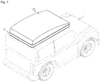
FIG. 1 is a perspective view illustrating a state in which a rooftop tent is fixed to a roof of a vehicle by a rooftop tent fixing device according to an embodiment of the present disclosure. -
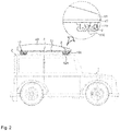
FIG. 2 is a side view of the state shown inFIG. 1 . -
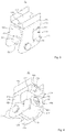
FIG. 3 is a front perspective view showing a clamp body of the rooftop tent fixing device shown inFIG. 2 . -
FIG. 4 is a rear perspective view showing the clamp body of the rooftop tent fixing device shown inFIG. 2 . -
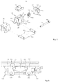
FIG. 5 is an exploded perspective view showing the rooftop tent fixing device shown inFIG. 2 . -
FIG. 6 is a side view showing a state in which the rooftop tent fixing device is fixed to a fixing beam having a shape different from that shown inFIG. 2 . - Hereinafter, specific embodiments for implementing the spirit of the present disclosure will be described in detail with reference to the drawings.
- In addition, in describing the present disclosure, if it is determined that a detailed description of a related known configuration or function may obscure the subject matter of the present disclosure, the detailed description thereof will be omitted.
- In addition, when one component is referred to as being 'connected' to another component, it should be understood that one component may be directly connected to another component and a further component may exist between one component and another component.
- The terms used in the subject specification are only used to describe specific embodiments, and are not intended to limit the present disclosure. Singular expressions include plural expressions unless the context clearly indicates otherwise.
- Hereinafter, a rooftop tent fixing device according to an embodiment of the present disclosure will be described with reference to the drawings.
- Referring to
FIGS. 1 and2 , arooftop tent 20 may be transported by being fixedly installed on aroof 2 of avehicle 1. In order to use therooftop tent 20 for residential purposes when arriving at a campsite, therooftop tent 20 is merely unfolded in a state in which therooftop tent 20 is mounted on theroof 2 of thevehicle 1, which makes it possible to completely install therooftop tent 20. Therooftop tent 20 may be installed so that the portion thereof protruding outside theroof 2 of thevehicle 1 can be supported by a member such as a ladder or the like after the installation is completed. - The
rooftop tent 20 may be detachably fixed to a mounting base 4 installed on theroof 2 of thevehicle 1 and afixing beam 3 fixedly installed so as to be supported by the mounting base 4. At this time, afixing frame 22 provided on the bottom of therooftop tent 20 is fixed to thefixing beam 3 by a rooftoptent fixing device 10, whereby therooftop tent 20 can be fixedly installed on theroof 2. The rooftoptent fixing device 10 is provided so as to be attachable and detachable through a simple operation, and may have a theft prevention function that prevents a third party from releasing the fixed state and separating the rooftop tent. - Hereinafter, a specific configuration of the rooftop
tent fixing device 10 according to an embodiment of the present disclosure will be described with reference to the drawings. - Referring to
FIGS. 3 to 5 , the rooftoptent fixing device 10 may include aclamp body 100, afastening member 200, afastening rod 300 and alocking member 420. - The
clamp body 100 is provided so as to be detachably fixed to thefixing frame 22 installed on the bottom surface of therooftop tent 20. Theclamp body 100 may be made of a material having high rigidity, for example, a steel-based material. Furthermore, twoclamp bodies 100 may be provided for onefixing beam 3, and may be provided on both sides of thefixing beam 3, respectively. In addition, as the distance between theclamp bodies 100 is reduced by afastening rod 300 in a state in which theclamp bodies 100 are respectively in contact with both sides of thefixing beam 3, theclamp bodies 100 and thefixing beams 3 may be fixed to each other by a pressure at which theclamp bodies 100 press thefixing beam 3 on both sides. - The
clamp body 100 may include afixing surface member 106 that comes into contact with thefixing frame 22 when theclamp body 100 is fixed to thefixing frame 22, and afirst side member 102 and asecond side member 104 formed to extend in one direction from both sides of thefixing surface member 106. At this time, thefixing surface member 106, thefirst side member 102 and thesecond side member 104 may be provided in a flat plate shape. Theclamp body 100 may have a "C" shape as a whole by being composed of thefixing surface member 106, thefirst side member 102 and thesecond side member 104. - A
fixing bracket 110 is fastened to thefixing surface member 106, and thefixing bracket 110 may be inserted into and fixed to thefixing frame 22. Such afixing bracket 110 may be fixed by being inserted into the internal space of the beam-shaped fixing frame 22 from the end portion. For example, after being inserted, thefixing bracket 110 may be fixed to the fixingframe 22 by fastening a bolt through afixing hole 108. - One edge of the
first side member 102 and one edge of thesecond side member 104 are formed asclamping edges 101 having a shape inclined with respect to thefixing surface member 106. Theclamping edges 101 may function as portions that make contact with thefixing beam 3. In other words, the portions that press thefixing beam 3 when theclamp bodies 100 come into contact with both sides of thefixing beam 3 and press thefixing beam 3 may become theclamping edges 101. In this case, theclamping edges 101 may have a curved shape, whereby theclamping edges 101 can be fixed by effectively making contact with and pressing thefixing beam 3 having a rectangular cross-section as shown inFIG. 2 as well as the fixing beam 3' having an elliptical cross-section as shown inFIG. 6 . In addition, theclamping edges 101 can effectively make contact with and press fixing beams of various shapes. - Fastening
holes 103 into which afastening member 200 is inserted and fastened are formed in thefirst side member 102 and thesecond side member 104. In addition, thefirst side member 102 and thesecond side member 104 have lockingholes 105 into which a lockingmember 422 of alock bolt 420 to be described later can be selectively inserted. Furthermore,insertion grooves 107 are formed on the edges of thefirst side member 102 and thesecond side member 104 opposite to the clamping edges 101. A lockingmember 400 is provided so as to be inserted into theinsertion grooves 107. In addition, a fixinghole 108 may be formed through the fixingsurface member 106. Such a fixinghole 108 may be formed to penetrate the fixingbracket 110. - A
fastening member 200 may be fastened to theclamp body 100 by being inserted into the fastening holes 103, and may have a through-hole 202 formed at the central portion thereof. Thefastening member 200 may be provided in a cylindrical beam shape, but the shape of thefastening member 200 is not necessarily limited to such a shape. Just like theclamp body 100, thefastening member 200 may be made of a material having high rigidity, for example, a steel-based material. - A
fastening rod 300 is provided so as to be inserted into the through-hole 202 of thefastening member 200. In addition, a male thread may be formed on at least a portion of the surface of thefastening rod 300, and a female thread corresponding thereto may be formed on the inner surface of the through-hole 202. Accordingly, when thefastening rod 300 is rotated while being inserted into the through-hole 202, the male and female threads may be engaged with each other so that thefastening rod 300 can be fixed. However, the spirit of the present disclosure is not limited thereto, and thefastening rod 300 and theclamp body 100 may be fastened to each other by a means other than the thread. Like theclamp body 100, thefastening rod 300 may be made of a material having high rigidity, for example, a steel-based material. - As shown in
FIG. 2 , oneclamp body 100 and theother clamp body 100 may be connected and fixed to each other by thefastening rod 300. At this time, as thefastening rod 300 is rotated in one direction in a state in which thefixing beam 3 installed on theroof 2 of thevehicle 1 is interposed between the twoclamp bodies 100 fixed by thefastening rod 300, the gap between the twoclamp bodies 100 becomes narrow, so that theclamp body 100 can be fixed to thefixing beam 3. Thefastening rod 300 may have ahead 302 formed at one end thereof. Thehead 302 may be provided with a cross or flat screw groove so that thefastening rod 300 can be rotated through the use of a tool such as a screwdriver or the like. - The locking
member 400 is selectively fixed to theclamp body 100 and provided so as to cover thefastening rod 300 when fixed to theclamp body 100. The lockingmember 400 may include alocking bracket 410 provided so as to be inserted into theinsertion grooves 107 formed in thefirst side member 102 and thesecond side member 104, and alock bolt 420 inserted through a lockbolt insertion hole 412 formed in thelocking bracket 410 and fastened to thelocking bracket 410. Just like theclamp body 100, the lockingmember 400 may be made of a material having high rigidity, for example, a steel-based material. - The locking
bracket 410 may include aninsertion portion 414 formed so as to be inserted into theinsertion groove 107, and coverportions 416 formed so as to cover the locking holes 105 when the lockingmember 400 is inserted into theclamp body 100. Theinsertion portion 414 is provided in a flat plate shape, and may have such a shape that a portion of both side edges (left and right edges inFIG. 5 ) protrudes more than other portions. By such a protruding portion, theinsertion portion 414 can be inserted into theinsertion grooves 107 formed in theclamp body 100. Thecover portions 416 may protrude in one direction by being bent from both ends of the protruding portion. In addition, a closingportion 418 may be bent to protrude from the other edge of the insertion portion 414 (the lower edge inFIG. 5 ) in the same direction as the direction in which thecover portions 416 protrude. The closingportion 418 may be provided to cover one side of thelocking bolt 420 when the lockingmember 400 is inserted into theclamp body 100, and may be provided to close at least one of the opening surfaces of the space between thefirst side member 102 and thesecond side member 104. In addition, the lockbolt insertion hole 412 may be formed through theinsertion portion 414. - The
lock bolt 420 includes a lockingmember 422 selectively inserted into one of the locking holes 105 formed in thefirst side member 102 and thesecond side member 104 as thelock bolt 420 is rotated in a state in which the lockingmember 400 is inserted into theinsertion grooves 107. - The locking
member 422 may be formed in such a shape as to protrude in a direction orthogonal to the bolt shape of thelock bolt 420 as shown inFIG. 5 . In the present embodiment, there is described a case where the lockingmember 422 is formed to extend in only one direction. However, the spirit of the present disclosure is not limited thereto. The lockingmember 422 may be formed to extend in both directions. In this case, lockingholes 105 may be formed in both thefirst side member 102 and thesecond side member 104. - In addition, a
key hole 424 may be formed in the head of therock bolt 420. Accordingly, the user may rotate a key corresponding to thekeyhole 424 in a predetermined direction in a state in which the key is inserted into thekeyhole 424, so that the lockingmember 422 passes through thelocking hole 105 to prevent the lockingmember 400 from being separated from the clampingbody 200. As a result, the lockingmember 400 cannot be separated from theclamp body 100 without the key corresponding to thekey hole 424. Since the fixing state of theclamp body 100 to thefixing beam 3 cannot be released without separating the lockingmember 400, it is possible to prevent the risk of theft. - Hereinafter, the operation and effect of the rooftop
tent fixing device 10 having the above-described configuration will be described. - In order to fix the
rooftop tent 20 using the rooftoptent fixing device 10 according to the present embodiment, the user may insert and fasten a plurality ofclamp bodies 100 into the fixingframe 22 installed on the bottom of therooftop tent 20. In this case, the number ofclamp bodies 100 may be twice the number of fixingbeams 3 provided on theroof 2. In other words, twoclamp bodies 100 may be fastened to onefixing beam 3. - The
rooftop tent 20 may be mounted on the upper side of theroof 2 in a state in which the clamp bodies100 are fastened to the fixingframe 22. In this case, theclamp bodies 100 may be disposed on both sides of each of the fixing beams 3. Thereafter, the positions of theclamp bodies 100 may be adjusted so that the clamping edges 101 of theclamp bodies 100 can make contact with both sides of the fixing beams 3. To this end, theclamp bodies 100 may be kept in a state in which the positions of theclamp bodies 100 are not fixed to the fixingframe 22 but are changeable. - When the
clamp bodies 100 come into contact with both sides of the fixingbeams 3, the user may reduce the gap between the twoclamp bodies 100 by rotating thefastening rod 300 that connects the twoclamp bodies 100 on both sides of each of the fixingbeams 3 to each other. Accordingly, theclamp bodies 100 are fixed to the fixingframe 22 in a state in which theclamp bodies 100 press the fixingbeams 3, so that the fixingframe 22 and the fixingbeams 3 can be fixed to each other. As a result, therooftop tent 20 and theroof 2 of thevehicle 1 may be fixed to each other. - After the fixing of the
rooftop tent 20 is completed, the lockingmember 400 may be inserted into and fixed to theclamp body 100 to prevent theft. To this end, the lockingbracket 410 into which thelocking bolt 420 of the lockingmember 400 is inserted may be inserted into theinsertion grooves 107 of theclamp body 100. As the user inserts the key into thekeyhole 424 and rotates the key in a predetermined direction in this state, the lockingmember 422 is rotated to pass through thelocking hole 105 of theclamp body 100 and is caught in thelocking hole 105. At this time, since the lockingmember 422 and the locking holes 105 are covered by thecover portions 416, the lockingmember 422 cannot be operated from the outside. In addition, since the opening surface, which is easily accessible from the outside, among the opening surfaces of the space between thefirst side member 102 and thesecond side member 104 is closed by the closingportion 418, it is also possible to prevent the access to thelock bolt 420 from the outside. - The rooftop
tent fixing device 10 according to the present embodiment as described above has an effect that it is easy and convenient to use when fixing therooftop tent 20 to theroof 2 of thevehicle 1, capable of providing a strong fixing force, and capable of effectively preventing theft of therooftop tent 20. - While the embodiments of the present disclosure have been described above as specific examples, these embodiments are nothing more than examples. The present disclosure is not limited thereto, and should be construed as having the widest scope in accordance with the basic idea disclosed herein. Those skilled in the art may combine or substitute the disclosed embodiments to implement a pattern of a shape not indicated herein. This also does not depart from the scope of the present disclosure. In addition, those skilled in the art may easily change or modify the disclosed embodiments based on the subject specification. It is apparent that such changes or modifications also belong to the scope of the present disclosure.
Claims (9)
- A rooftop tent fixing device, comprising:clamp bodies detachably fixed to a fixing frame installed on a bottom of a rooftop tent, each of the clamp bodies including a fixing surface member configured to make contact with the fixing frame when the clamp bodies are fixed to the fixing frame, and a first side member and a second side member formed to extend in one direction from both side edges of the fixing surface member;a fastening member inserted into and fastened to fastening holes formed in the first side member and the second side member of each of the clamp bodies, the fastening member having a through-hole; anda fastening rod provided to be inserted into the through-hole of the fastening member,wherein the clamp bodies are fixed to a fixing beam as a gap between the clamp bodies is reduced by rotating the fastening rod in one direction in a state in which one of the clamp bodies and the other clamp body are connected and fixed to each other by the fastening rod and in which the fixing beam installed on a roof of a vehicle is interposed between the clamp bodies fixed by the fastening rod.
- The device of claim 1, wherein each of the clamp bodies further includes a fixing bracket fastened to the fixing surface member and capable of being inserted into and fixed to the fixing frame.
- The device of claim 1, wherein one edges of the first side member and the second side member are formed as clamping edges having a shape inclined with respect to the fixing surface member.
- The device of claim 3, wherein the clamping edges have a curved shape.
- The device of claim 1, further comprising:
a locking member configured to be selectively fixed to the clamp bodies and to cover the fastening rod when fixed to the clamp bodies. - The device of claim 5, wherein one edge of at least one of the first side member and the second side member is formed as a clamping edge having a shape inclined with respect to the fixing surface member, and
the locking member includes a locking bracket provided so as to be inserted into an insertion groove formed at an edge opposite to the one edge of at least one of the first side member and the second side member, and a lock bolt inserted through a lock bolt insertion hole formed in the locking bracket and fastened to the locking bracket. - The device of claim 6, wherein the lock bolt includes a locking member selectively inserted into a locking hole formed in at least one of the first side member and the second side member by rotation of the lock bolt in a state in which the locking member is inserted into the insertion groove.
- The device of claim 7, wherein the locking bracket includes an insertion portion formed so as to be inserted into the insertion groove, and a cover portion formed so as to cover the locking hole when the locking member is inserted into each of the clamp bodies, and
the lock bolt insertion hole is formed through the insertion portion. - The device of claim 8, wherein the locking bracket further includes a closing portion bent in one direction so as to protrude from one edge of the insertion portion.
Applications Claiming Priority (2)
| Application Number | Priority Date | Filing Date | Title |
|---|---|---|---|
| KR1020180100617A KR20200024007A (en) | 2018-08-27 | 2018-08-27 | Fixing device for roof-top tent |
| PCT/KR2019/010946 WO2020045961A1 (en) | 2018-08-27 | 2019-08-27 | Rooftop tent fixing device |
Publications (2)
| Publication Number | Publication Date |
|---|---|
| EP3845726A1 true EP3845726A1 (en) | 2021-07-07 |
| EP3845726A4 EP3845726A4 (en) | 2021-11-03 |
Family
ID=69644629
Family Applications (1)
| Application Number | Title | Priority Date | Filing Date |
|---|---|---|---|
| EP19853379.6A Withdrawn EP3845726A4 (en) | 2018-08-27 | 2019-08-27 | Rooftop tent fixing device |
Country Status (6)
| Country | Link |
|---|---|
| US (1) | US20240247516A1 (en) |
| EP (1) | EP3845726A4 (en) |
| KR (1) | KR20200024007A (en) |
| CN (1) | CN112823231A (en) |
| DE (1) | DE202019005908U1 (en) |
| WO (1) | WO2020045961A1 (en) |
Cited By (1)
| Publication number | Priority date | Publication date | Assignee | Title |
|---|---|---|---|---|
| EP4141199A4 (en) * | 2021-07-13 | 2024-04-03 | iKamper Co., Ltd. | Rooftop tent fixing apparatus and rooftop tent comprising same |
Families Citing this family (7)
| Publication number | Priority date | Publication date | Assignee | Title |
|---|---|---|---|---|
| DE102021000001A1 (en) | 2020-01-02 | 2021-07-08 | Christoph Michael Gaebel | Counter plate for a roof load attachment and additional device for it |
| CN116997487A (en) | 2021-03-19 | 2023-11-03 | 拓乐瑞典股份公司 | Vehicle roof load bar mounting system |
| KR20220155637A (en) * | 2021-05-17 | 2022-11-24 | 주식회사 아이캠퍼 | Roof-top tent and assembling method of same |
| KR102625483B1 (en) * | 2021-07-13 | 2024-01-17 | 주식회사 아이캠퍼 | Fixing device for roof-top tent and roof-top tent including same |
| US12214712B1 (en) * | 2022-12-27 | 2025-02-04 | Cameron Andrews | Vehicle roof-mounted collapsible tent |
| USD1074831S1 (en) * | 2023-05-05 | 2025-05-13 | Porsche Design Gmbh | Rooftop tent for motor vehicle |
| USD1062586S1 (en) * | 2024-02-21 | 2025-02-18 | 56 Nord Ab | Roof cargo box |
Family Cites Families (15)
| Publication number | Priority date | Publication date | Assignee | Title |
|---|---|---|---|---|
| GB2302852B (en) * | 1995-06-30 | 1998-11-11 | Jac Products Inc | Adjustable clamp for use with a vehicle article carrier |
| SE504606C2 (en) * | 1995-09-26 | 1997-03-17 | Mont Blanc Ind Ab | Device for vehicle-mounted load carriers |
| KR20030011381A (en) * | 2003-01-06 | 2003-02-07 | 임경도 | Car tent |
| AU2003231688A1 (en) * | 2003-01-31 | 2004-08-19 | Roof Rack Industries Pty Ltd | Rail Bar Roof Rack |
| KR200352877Y1 (en) * | 2003-12-30 | 2004-06-14 | 김성기 | Tent installation jig |
| KR100555135B1 (en) * | 2004-06-25 | 2006-02-24 | 주식회사 버팔로 | Car Folding Tent |
| CN203383573U (en) * | 2011-12-22 | 2014-01-08 | 姜宁 | Vehicle roof tent with roof skylight as inlet/outlet |
| CN203093916U (en) * | 2013-01-18 | 2013-07-31 | 宁波纽特汽车配件有限公司 | Automobile longitudinal baggage holder |
| US9085266B2 (en) * | 2013-12-02 | 2015-07-21 | Pu-Lun Chang | Structure of roof rack |
| CN205131110U (en) * | 2015-10-16 | 2016-04-06 | 宁波立博汽车配件有限公司 | Car roof luggage carrier |
| CN109642434B (en) * | 2016-06-05 | 2021-04-27 | 雅捷马产品公司 | Vehicle Roof Support Assembly |
| CN205836690U (en) * | 2016-07-21 | 2016-12-28 | 秋野地(厦门)户外装备科技有限公司 | Luggage carrier fixation kit |
| KR101881254B1 (en) * | 2017-05-01 | 2018-07-23 | 송중무 | Multi-purpose supporting frame mounted on the roof-rack of a car |
| CN207207721U (en) * | 2017-05-19 | 2018-04-10 | 黄佳艺 | A kind of hood |
| CN108316748A (en) * | 2018-02-11 | 2018-07-24 | 秋野地(厦门)户外装备科技有限公司 | A kind of tent holder |
-
2018
- 2018-08-27 KR KR1020180100617A patent/KR20200024007A/en not_active Ceased
-
2019
- 2019-08-27 WO PCT/KR2019/010946 patent/WO2020045961A1/en not_active Ceased
- 2019-08-27 US US17/271,574 patent/US20240247516A1/en not_active Abandoned
- 2019-08-27 EP EP19853379.6A patent/EP3845726A4/en not_active Withdrawn
- 2019-08-27 DE DE202019005908.3U patent/DE202019005908U1/en active Active
- 2019-08-27 CN CN201980067034.3A patent/CN112823231A/en active Pending
Cited By (1)
| Publication number | Priority date | Publication date | Assignee | Title |
|---|---|---|---|---|
| EP4141199A4 (en) * | 2021-07-13 | 2024-04-03 | iKamper Co., Ltd. | Rooftop tent fixing apparatus and rooftop tent comprising same |
Also Published As
| Publication number | Publication date |
|---|---|
| US20240247516A1 (en) | 2024-07-25 |
| DE202019005908U1 (en) | 2023-02-17 |
| CN112823231A (en) | 2021-05-18 |
| EP3845726A4 (en) | 2021-11-03 |
| WO2020045961A1 (en) | 2020-03-05 |
| KR20200024007A (en) | 2020-03-06 |
Similar Documents
| Publication | Publication Date | Title |
|---|---|---|
| US20240247516A1 (en) | Rooftop tent fixing device | |
| US6588543B1 (en) | Spring-loaded dog assembly which enables a bezel of a speaker system and structure holding electric device to be mounted in ceilings and walls without having to use external retaining means | |
| US10808416B2 (en) | Roof-top tent for vehicle | |
| US5584311A (en) | Self-supported tent frame coupler | |
| US11971062B2 (en) | Mounting system | |
| US5074136A (en) | Magnetic lock device | |
| MXPA03010738A (en) | Pull pin assembly for canopy. | |
| US5503212A (en) | Solar shield device for a vehicle | |
| US12209427B2 (en) | Rooftop tent fixing device and rooftop tent including same | |
| US20060131551A1 (en) | Retractable barrier | |
| US20060065494A1 (en) | Wheel locking device for vehicle | |
| US20150089901A1 (en) | Utility pole assembly | |
| US10800337B2 (en) | Device for securing an area in a vehicle | |
| KR102484612B1 (en) | A prefabricated modular housing | |
| KR102625483B1 (en) | Fixing device for roof-top tent and roof-top tent including same | |
| WO2013154416A1 (en) | Utility pole assembly | |
| CN206279866U (en) | One kind slides limit button | |
| JPH1030366A (en) | Fitting metal tool of metallic mesh for fence | |
| CN112701442B (en) | Self-locking mounting bracket and radome structure applying same | |
| KR20200000596U (en) | Car Tent | |
| KR20100111450A (en) | Portable type blind tent | |
| CA3073420A1 (en) | Fastener for swimming pool step assembly, and method of assembly | |
| CN218759135U (en) | Tent for vehicle | |
| JP2802989B2 (en) | Base frame for wall plate and mounting fixture for base frame | |
| WO2025047689A1 (en) | Simple tent engagement fixture |
Legal Events
| Date | Code | Title | Description |
|---|---|---|---|
| STAA | Information on the status of an ep patent application or granted ep patent |
Free format text: STATUS: THE INTERNATIONAL PUBLICATION HAS BEEN MADE |
|
| STAA | Information on the status of an ep patent application or granted ep patent |
Free format text: STATUS: REQUEST FOR EXAMINATION WAS MADE |
|
| PUAI | Public reference made under article 153(3) epc to a published international application that has entered the european phase |
Free format text: ORIGINAL CODE: 0009012 |
|
| 17P | Request for examination filed |
Effective date: 20210323 |
|
| AK | Designated contracting states |
Kind code of ref document: A1 Designated state(s): AL AT BE BG CH CY CZ DE DK EE ES FI FR GB GR HR HU IE IS IT LI LT LU LV MC MK MT NL NO PL PT RO RS SE SI SK SM TR |
|
| REG | Reference to a national code |
Ref country code: DE Ref legal event code: R079 Free format text: PREVIOUS MAIN CLASS: E04H0015060000 Ipc: B60R0009055000 |
|
| STAA | Information on the status of an ep patent application or granted ep patent |
Free format text: STATUS: EXAMINATION IS IN PROGRESS |
|
| A4 | Supplementary search report drawn up and despatched |
Effective date: 20211006 |
|
| RIC1 | Information provided on ipc code assigned before grant |
Ipc: B60R 9/058 20060101ALI20210930BHEP Ipc: B60R 9/055 20060101AFI20210930BHEP |
|
| 17Q | First examination report despatched |
Effective date: 20211102 |
|
| DAV | Request for validation of the european patent (deleted) | ||
| DAX | Request for extension of the european patent (deleted) | ||
| STAA | Information on the status of an ep patent application or granted ep patent |
Free format text: STATUS: THE APPLICATION IS DEEMED TO BE WITHDRAWN |
|
| 18D | Application deemed to be withdrawn |
Effective date: 20230301 |