EP3845461A1 - Radialverschiebungsbegrenzer für zweiachsiges gelenk - Google Patents
Radialverschiebungsbegrenzer für zweiachsiges gelenk Download PDFInfo
- Publication number
- EP3845461A1 EP3845461A1 EP21150276.0A EP21150276A EP3845461A1 EP 3845461 A1 EP3845461 A1 EP 3845461A1 EP 21150276 A EP21150276 A EP 21150276A EP 3845461 A1 EP3845461 A1 EP 3845461A1
- Authority
- EP
- European Patent Office
- Prior art keywords
- cowl
- hinge
- dual axis
- link
- stop
- Prior art date
- Legal status (The legal status is an assumption and is not a legal conclusion. Google has not performed a legal analysis and makes no representation as to the accuracy of the status listed.)
- Granted
Links
Images


Classifications
-
- B—PERFORMING OPERATIONS; TRANSPORTING
- B64—AIRCRAFT; AVIATION; COSMONAUTICS
- B64D—EQUIPMENT FOR FITTING IN OR TO AIRCRAFT; FLIGHT SUITS; PARACHUTES; ARRANGEMENT OR MOUNTING OF POWER PLANTS OR PROPULSION TRANSMISSIONS IN AIRCRAFT
- B64D29/00—Power-plant nacelles, fairings or cowlings
- B64D29/06—Attaching of nacelles, fairings or cowlings
-
- E—FIXED CONSTRUCTIONS
- E05—LOCKS; KEYS; WINDOW OR DOOR FITTINGS; SAFES
- E05D—HINGES OR SUSPENSION DEVICES FOR DOORS, WINDOWS OR WINGS
- E05D11/00—Additional features or accessories of hinges
- E05D11/06—Devices for limiting the opening movement of hinges
-
- E—FIXED CONSTRUCTIONS
- E05—LOCKS; KEYS; WINDOW OR DOOR FITTINGS; SAFES
- E05D—HINGES OR SUSPENSION DEVICES FOR DOORS, WINDOWS OR WINGS
- E05D3/00—Hinges with pins
- E05D3/06—Hinges with pins with two or more pins
- E05D3/12—Hinges with pins with two or more pins with two parallel pins and one arm
- E05D3/125—Hinges with pins with two or more pins with two parallel pins and one arm specially adapted for vehicles
-
- E—FIXED CONSTRUCTIONS
- E05—LOCKS; KEYS; WINDOW OR DOOR FITTINGS; SAFES
- E05Y—INDEXING SCHEME ASSOCIATED WITH SUBCLASSES E05D AND E05F, RELATING TO CONSTRUCTION ELEMENTS, ELECTRIC CONTROL, POWER SUPPLY, POWER SIGNAL OR TRANSMISSION, USER INTERFACES, MOUNTING OR COUPLING, DETAILS, ACCESSORIES, AUXILIARY OPERATIONS NOT OTHERWISE PROVIDED FOR, APPLICATION THEREOF
- E05Y2900/00—Application of doors, windows, wings or fittings thereof
- E05Y2900/50—Application of doors, windows, wings or fittings thereof for vehicles
- E05Y2900/502—Application of doors, windows, wings or fittings thereof for vehicles for aircraft or spacecraft
Definitions
- the present invention relates generally to turbofan propulsion systems for aircraft and, more particularly, to radial displacement limiting hinge systems for a cowl in a nacelle for a turbofan propulsion system.
- Modern aircraft may utilize one or more turbofan propulsion systems powered by a gas turbine engine.
- the propulsion systems may include a nacelle, which is a system of components that house the engine and its ancillary systems, and help form aerodynamic surfaces for flight, including a fan bypass air duct.
- the nacelle includes a cowl or a pair of cowls.
- the cowl is typically hinged to a fix structure, such as, for example, a pylon, and facilitates access to the engine and the ancillary systems when opened.
- the cowl also defines an annular shaped compartment that surrounds an inner fixed structure and in which several ducts carrying high pressure fluids or gases reside.
- a dual axis hinge configured for pivotally securing a cowl to a fixed structure of an aircraft.
- the dual axis hinge includes a link having a first end and a second end, a first pin configured to pivotally secure the first end of the link to the fixed structure and a second pin configured to pivotally secure the second end of the link to the cowl, and a first hinge stop configured for connection to the cowl and a second hinge stop configured for connection to the link.
- the first hinge stop is configured for connection to a cowl flange.
- the cowl flange is configured for attachment to an inside surface of the cowl.
- the second hinge stop is connected to the second end of the link.
- the first hinge stop includes a first face and the second hinge stop includes a second face configured to abut the first face when the cowl is rotated toward a closed position.
- the first face and the second face are configured to separate when the cowl is rotated toward an open position.
- the fixed structure is a pylon.
- the first pin is connected to a pylon flange connected to and extending from the pylon.
- the first pin is configured for coaxial disposition with a hinge line of the cowl.
- a cowl system for a nacelle of an aircraft includes a fixed structure; and a cowl pivotally mounted to the fixed structure via a dual axis hinge, the dual axis hinge including a link having a first end and a second end, a first pin configured to pivotally secure the first end of the link to the fixed structure and a second pin configured to pivotally secure the second end of the link to the cowl, and a first hinge stop connected to the cowl and a second hinge stop connected to the link.
- the first hinge stop is connected to a cowl flange.
- the cowl flange is attached to an inside surface of the cowl.
- the second hinge stop is connected to the second end of the link.
- the first hinge stop includes a first face and the second hinge stop includes a second face configured to abut the first face when the cowl is rotated toward a closed position.
- the first face and the second face are configured to separate when the cowl is rotated toward an open position.
- the fixed structure is a pylon.
- the first pin is connected to a pylon flange connected to and extending from the pylon.
- the first pin is configured for coaxial disposition with a hinge line of the cowl.
- the cowl system further includes a second hinge, a third hinge and a fourth hinge pivotally mounting the cowl to the fixed structure.
- the second hinge includes a clevis and a lug.
- references to "a,” “an” or “the” may include one or more than one and that reference to an item in the singular may also include the item in the plural. Further, all ranges may include upper and lower values and all ranges and ratio limits disclosed herein may be combined.
- the gas turbine engine 100 includes a nacelle 102 that surrounds a core engine structure.
- the nacelle 102 includes an air inlet 104, a cowl 106 and a thrust reverser 108.
- the nacelle 102 may be coupled to a pylon 110, which may mount the nacelle 102 and the core engine structure to an aircraft wing or aircraft body.
- the nacelle 102 may further include an exhaust nozzle assembly including a nozzle 112 and an aft cowl 114 surrounding a center body 116 having a generally conical shape and, in various embodiments, an associated attachment structure.
- a high-temperature exhaust stream from the core engine structure exits the gas turbine engine 100 between the nozzle 112 and the center body 116.
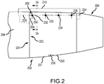
- FIG. 2 there is seen a schematic side view of a gas turbine engine 200 mounted on a pylon 210, which may be secured to an underside of an aircraft wing or to a portion of a fuselage of the aircraft.
- a nacelle 202 surrounds a core engine structure and various related components of the gas turbine engine 200.
- a cowl 220 (or a first cowl) is hingedly (e.g., mounted by a hinge) mounted to the pylon 210 in a manner permitting the cowl 220 to be rotated upward and away from the gas turbine engine 200, thereby exposing the core engine structure and various related components to permit access for examination or repair.
- a second cowl (hidden) is hingedly mounted on the opposite side of the pylon 210.
- the cowl 220 pivots on four hinge assemblies located just within the cowl 220 and not seen in FIG. 2 .
- the cowl 220 typically pivots about a hinge line 224 defined by the locations of the four hinge assemblies, including a first hinge assembly 230, a second hinge assembly 232, a third hinge assembly 234 and a fourth hinge assembly 236.
- a cowl lock 238 is positioned at a lower end 231 of the cowl 220 and configured to maintain the cowl 220 in the closed position during operation.
- One or more of the four hinge assemblies may comprise a conventional clevis and lug coupled together via a pin that extends coaxially with the hinge line 224.
- one or more of the four hinge assemblies, and particularly the first hinge assembly 230 comprise a dual axis hinge 250, which is defined, at least in part, by a first axis 252 that is coaxial with the hinge line 224 and a second axis 254 that is offset from the hinge line 224.
- the dual axis hinge 250 is configured to limit radial displacement of a forward edge 223 of the cowl 220 in a radially outward direction with respect to an aft edge 225 of an air inlet 204 of the nacelle 202 when the cowl 220 assumes a closed position. Limiting radial displacement of the forward edge 223 of the cowl 220 from moving in a radially outward direction, or otherwise limiting or controlling the size of a radial gap caused by such movement, prevents the phenomena known as scooping, as above described.
- a dual axis hinge 350 similar to the dual axis hinge 250 described above with reference to FIG. 2 , is illustrated connected to a cowl 320 in a closed position (see FIG. 3A ) and in an open position (see FIG. 3B ).
- the dual axis hinge 350 includes a link 360 having a first end 361 pivotally secured to a fixed structure, such as, for example, a pylon 310 or a pylon flange 311 connected to and extending from the pylon 310, and a second end 363 pivotally secured to the cowl 320.
- a first pin 362 is used to secure the first end 361 of the link 360 to the fixed structure, with the first pin 362 extending axially along a first axis 352.
- the first axis 352 is coaxial with a hinge line 324 of the cowl 320, similar to the hinge line 224 described above with reference to FIG. 2 .
- a second pin 364 is used to secure the second end 363 of the link 360 to the cowl 320 or to a cowl flange 321 connected to and extending from an inside surface 327 of the cowl 320, with the second pin 364 extending axially along a second axis 354.
- the second axis 354 is offset from the first axis 352, as well as the hinge line 324 of the cowl 320, similar to the arrangement described above with reference to FIG. 2 .
- a first hinge stop 366 is connected to the inside surface 327 of the cowl 320 via the cowl flange 321 and a second hinge stop 368 is connected to the link 360 proximate the second end 363 of the link 360.
- the connection of the first hinge stop 366 to the cowl 320 is typically a rigid connection, such that the first hinge stop 366 is prevented from movement with respect to the cowl 320.
- the first hinge stop 366 is welded or bolted to the cowl flange 321 or, in various embodiments, the first hinge stop 366 and the cowl flange 321 are constructed as a monolithic or single-piece unit.
- connection of the second hinge stop 368 to the link 360 is typically a rigid connection, such that the second hinge stop 368 is prevented from movement with respect to the link 360.
- the second hinge stop 368 is welded or bolted to the second end 363 of the link 360 or, in various embodiments, the second hinge stop 368 and the link 360 are constructed as a monolithic or single-piece unit.
- the first hinge stop 366 includes a first face 367 and the second hinge stop 368 includes a second face 369 configured to abut the first face 367 when the cowl 320 assumes a closed position.
- the first hinge stop 366 and the second hinge stop 368 contact one another. More specifically, in various embodiments, when the cowl 320 assumes the closed position, the first face 367 of the first hinge stop 366 and the second face 369 of the second hinge stop 368 abut one another. The manner of contact prevents an upper portion 329 of the cowl 320 from moving or otherwise being displaced in a radial direction R in response to a load or a force F acting in the radial direction R on the inside surface 327 of the cowl 320.
- a cowl lock such as, for example, the cowl lock 238 described above with reference to FIG.
- the cowl 320 will be secured at a lower end 331 of the cowl 320 in order to prevent the dual axis hinge 350 from rotating about the first axis 352 in response to the load or the force F acting in the radial direction R on the inside surface 327 of the cowl 320.
- the cowl 320 is able to rotate with respect to second end 363 of the link 360 in a direction that enables a space to be created between the first face 367 and the second face 369.
- the link 360 is able to rotate about the first axis 352, which, as described above, is typically coaxial with the hinge line 324. This enables the various hinges pivotally connecting the cowl 320 to the fixed structure (e.g., to the pylon 310 or to the pylon flange 311) to rotate about the hinge line 324 such that the cowl may assume the open position.
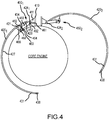
- the cowl system 400 includes a first cowl 420 1 and a second cowl 420 2 pivotally secured to a fixed structure, such as, for example, a pylon 410 or a pylon flange 411 connected to and extending from the pylon 410.
- a first dual axis hinge 450i includes a link 460 having a first end 461 pivotally secured to the fixed structure and a second end 463 pivotally secured to the first cowl 420 1 .
- a first pin 462 is used to secure the first end 461 of the link 460 to the fixed structure, with the first pin 462 extending axially along a first axis 452, the first axis 452 being coaxial with a first hinge line 424 1 of the first cowl 420 1 , similar to the hinge line 324 described above with reference to FIGS. 3A and 3B .
- a second pin 464 is used to secure the second end 463 of the link 460 to the first cowl 420 1 or to a cowl flange 421 connected to and extending from an inside surface 427 of the first cowl 420 1 , with the second pin 464 extending axially along a second axis 454.
- the second axis 454 is offset from the first axis 452, as well as the first hinge line 424 1 of the first cowl 420 1 , similar to the arrangement described above with reference to FIGS. 2 , 3A and 3B .
- a first hinge stop 466 is connected to the inside surface 427 of the first cowl 420 1 via the cowl flange 421 and a second hinge stop 468 is connected to the link 460 proximate the second end 463 of the link 460.
- the connections of the first hinge stop 466 to the first cowl 420 1 via the cowl flange 421 and the second hinge stop 468 to the link 460 proximate the second end 463 of the link 460 are similar to those described above with reference to FIGS. 3A and 3B .
- the second cowl 420 2 is pivotally secured to the fixed structure via a second dual axis hinge 450 2 , which includes each of the components described above with reference to the first dual axis hinge 450 1 .
- a cowl lock 438 is used to lock the first cowl 420 1 and the second cowl 420 2 in place while in the closed position.
- several additional hinges which may include conventional clevis and lug hinges, may be disposed along both the first hinge line 424 1 and the second hinge line 424 2 to pivotally mount, respectively, the first cowl 420 1 and the second cowl 420 2 to the fixed structure ( e.g., to the pylon 410).
- first hinge stop 466 and the second hinge stop 468 contact one another.
- the manner of contact prevents an upper portion 429 of the first cowl 420 1 from moving or otherwise being displaced in a radial direction R in response to a load or a force F acting in a radial direction R on the inside surface 427 of the first cowl 420 1 , in a manner similar to that described above with reference to FIGS. 3A and 3B .
- the cowl lock 438 will be secured at a lower end 431 of the first cowl 420 1 in order to prevent the first dual axis hinge 450 1 from rotating about the first axis 452 or the first hinge line 424 1 in response to the load or the force F acting in the radial direction R on the inside surface 427 of the first cowl 420 1 .
- the second cowl 420 2 once the cowl lock 438 at the lower end 431 of the second cowl 420 2 is released, the second cowl 420 2 is able to rotate about the second hinge line 424 2 .
- references to "one embodiment,” “an embodiment,” “various embodiments,” etc. indicate that the embodiment described may include a particular feature, structure, or characteristic, but every embodiment may not necessarily include the particular feature, structure, or characteristic. Moreover, such phrases are not necessarily referring to the same embodiment. Further, when a particular feature, structure, or characteristic is described in connection with an embodiment, it is submitted that it is within the knowledge of one skilled in the art to affect such feature, structure, or characteristic in connection with other embodiments whether or not explicitly described. After reading the description, it will be apparent to one skilled in the relevant art(s) how to implement the disclosure in alternative embodiments.
Landscapes
- Engineering & Computer Science (AREA)
- Mechanical Engineering (AREA)
- Aviation & Aerospace Engineering (AREA)
- Pivots And Pivotal Connections (AREA)
- Body Structure For Vehicles (AREA)
Applications Claiming Priority (1)
| Application Number | Priority Date | Filing Date | Title |
|---|---|---|---|
| US16/735,110 US11731774B2 (en) | 2020-01-06 | 2020-01-06 | Dual axis hinge radial displacement limiter |
Publications (2)
| Publication Number | Publication Date |
|---|---|
| EP3845461A1 true EP3845461A1 (de) | 2021-07-07 |
| EP3845461B1 EP3845461B1 (de) | 2025-07-16 |
Family
ID=74103984
Family Applications (1)
| Application Number | Title | Priority Date | Filing Date |
|---|---|---|---|
| EP21150276.0A Active EP3845461B1 (de) | 2020-01-06 | 2021-01-05 | Radialverschiebungsbegrenzer für zweiachsiges gelenk |
Country Status (2)
| Country | Link |
|---|---|
| US (1) | US11731774B2 (de) |
| EP (1) | EP3845461B1 (de) |
Families Citing this family (1)
| Publication number | Priority date | Publication date | Assignee | Title |
|---|---|---|---|---|
| US20250305454A1 (en) * | 2024-03-28 | 2025-10-02 | General Electric Company | Gas turbine engine with heat exchanger assembly |
Citations (3)
| Publication number | Priority date | Publication date | Assignee | Title |
|---|---|---|---|---|
| WO1995011361A1 (en) * | 1993-10-20 | 1995-04-27 | United Technologies Corporation | Aircraft duplex hinge assembly |
| US20180216379A1 (en) * | 2017-01-31 | 2018-08-02 | Hartwell Corporation | Four-bar linkage hinge |
| EP3539879A1 (de) * | 2018-03-13 | 2019-09-18 | Airbus Operations S.A.S. | Doppelströmung-turbotriebwerk für ein luftfahrzeug mit einer öffnung, die mit einem scharnier mit schwanenhalsbeschlag ausgestattet ist |
Family Cites Families (5)
| Publication number | Priority date | Publication date | Assignee | Title |
|---|---|---|---|---|
| US5203525A (en) * | 1991-10-23 | 1993-04-20 | Rohr, Inc. | Hinge with offset pivot line |
| US5864922A (en) * | 1996-08-08 | 1999-02-02 | The Boeing Company | Self centering hinge |
| US6189832B1 (en) * | 1998-04-03 | 2001-02-20 | Hartwell Corporation | Permanently connected remote latch mechanism |
| FR2939410B1 (fr) | 2008-12-04 | 2012-06-15 | Airbus France | Systeme de fermeture d'un capot de soufflante pour aeronef |
| WO2015017492A1 (en) | 2013-07-30 | 2015-02-05 | General Electric Company | Thrust reverser system with translating-rotating hinge assembly |
-
2020
- 2020-01-06 US US16/735,110 patent/US11731774B2/en active Active
-
2021
- 2021-01-05 EP EP21150276.0A patent/EP3845461B1/de active Active
Patent Citations (3)
| Publication number | Priority date | Publication date | Assignee | Title |
|---|---|---|---|---|
| WO1995011361A1 (en) * | 1993-10-20 | 1995-04-27 | United Technologies Corporation | Aircraft duplex hinge assembly |
| US20180216379A1 (en) * | 2017-01-31 | 2018-08-02 | Hartwell Corporation | Four-bar linkage hinge |
| EP3539879A1 (de) * | 2018-03-13 | 2019-09-18 | Airbus Operations S.A.S. | Doppelströmung-turbotriebwerk für ein luftfahrzeug mit einer öffnung, die mit einem scharnier mit schwanenhalsbeschlag ausgestattet ist |
Also Published As
| Publication number | Publication date |
|---|---|
| EP3845461B1 (de) | 2025-07-16 |
| US20210206500A1 (en) | 2021-07-08 |
| US11731774B2 (en) | 2023-08-22 |
Similar Documents
| Publication | Publication Date | Title |
|---|---|---|
| EP3907139B1 (de) | Systeme und verfahren zur längenanpassung eines verriegelungshakens | |
| US9714627B2 (en) | Mounting of aircraft propulsion system outer sleeve and inner structure to pylon with distinct hinges | |
| US11300076B2 (en) | Propulsion unit including lifting points disposed on thrust reverser cylinder supports | |
| EP3549856A1 (de) | Lüfterhaubenverriegelungskonzept für ein rumpfmontiertes triebwerk | |
| US20180362172A1 (en) | Hinge assembly | |
| US11542027B2 (en) | Pressure relief assembly | |
| US11718409B2 (en) | Nacelle with independent opening thrust reverser section | |
| EP3326916B1 (de) | Gondelverriegelungsausrichtung | |
| EP3845461A1 (de) | Radialverschiebungsbegrenzer für zweiachsiges gelenk | |
| US11536064B2 (en) | Self-engaging fan cowl hook latch | |
| US10954888B2 (en) | Hybrid pivot door thrust reversers | |
| EP4257481A1 (de) | Gondeleinlassstrukturanpassung mit positionsklammer und hebeklammer | |
| EP3663207B1 (de) | Geführtes scharnier für triebwerksverkleidung | |
| US11149564B2 (en) | Nacelle thrust reverser compression rod supporting system | |
| US11525372B2 (en) | Diaphragm latch | |
| EP4019407B1 (de) | Ausfallsichere lüfterhaubenschwanenhalsanordnung |
Legal Events
| Date | Code | Title | Description |
|---|---|---|---|
| PUAI | Public reference made under article 153(3) epc to a published international application that has entered the european phase |
Free format text: ORIGINAL CODE: 0009012 |
|
| STAA | Information on the status of an ep patent application or granted ep patent |
Free format text: STATUS: THE APPLICATION HAS BEEN PUBLISHED |
|
| AK | Designated contracting states |
Kind code of ref document: A1 Designated state(s): AL AT BE BG CH CY CZ DE DK EE ES FI FR GB GR HR HU IE IS IT LI LT LU LV MC MK MT NL NO PL PT RO RS SE SI SK SM TR |
|
| STAA | Information on the status of an ep patent application or granted ep patent |
Free format text: STATUS: REQUEST FOR EXAMINATION WAS MADE |
|
| 17P | Request for examination filed |
Effective date: 20220107 |
|
| RBV | Designated contracting states (corrected) |
Designated state(s): AL AT BE BG CH CY CZ DE DK EE ES FI FR GB GR HR HU IE IS IT LI LT LU LV MC MK MT NL NO PL PT RO RS SE SI SK SM TR |
|
| STAA | Information on the status of an ep patent application or granted ep patent |
Free format text: STATUS: EXAMINATION IS IN PROGRESS |
|
| 17Q | First examination report despatched |
Effective date: 20221109 |
|
| GRAP | Despatch of communication of intention to grant a patent |
Free format text: ORIGINAL CODE: EPIDOSNIGR1 |
|
| STAA | Information on the status of an ep patent application or granted ep patent |
Free format text: STATUS: GRANT OF PATENT IS INTENDED |
|
| INTG | Intention to grant announced |
Effective date: 20250207 |
|
| GRAS | Grant fee paid |
Free format text: ORIGINAL CODE: EPIDOSNIGR3 |
|
| GRAA | (expected) grant |
Free format text: ORIGINAL CODE: 0009210 |
|
| STAA | Information on the status of an ep patent application or granted ep patent |
Free format text: STATUS: THE PATENT HAS BEEN GRANTED |
|
| AK | Designated contracting states |
Kind code of ref document: B1 Designated state(s): AL AT BE BG CH CY CZ DE DK EE ES FI FR GB GR HR HU IE IS IT LI LT LU LV MC MK MT NL NO PL PT RO RS SE SI SK SM TR |
|
| REG | Reference to a national code |
Ref country code: GB Ref legal event code: FG4D |
|
| REG | Reference to a national code |
Ref country code: CH Ref legal event code: EP Ref country code: DE Ref legal event code: R096 Ref document number: 602021034024 Country of ref document: DE |
|
| REG | Reference to a national code |
Ref country code: IE Ref legal event code: FG4D |
|
| REG | Reference to a national code |
Ref country code: NL Ref legal event code: MP Effective date: 20250716 |
|
| PG25 | Lapsed in a contracting state [announced via postgrant information from national office to epo] |
Ref country code: PT Free format text: LAPSE BECAUSE OF FAILURE TO SUBMIT A TRANSLATION OF THE DESCRIPTION OR TO PAY THE FEE WITHIN THE PRESCRIBED TIME-LIMIT Effective date: 20251117 |
|
| PG25 | Lapsed in a contracting state [announced via postgrant information from national office to epo] |
Ref country code: NL Free format text: LAPSE BECAUSE OF FAILURE TO SUBMIT A TRANSLATION OF THE DESCRIPTION OR TO PAY THE FEE WITHIN THE PRESCRIBED TIME-LIMIT Effective date: 20250716 |
|
| REG | Reference to a national code |
Ref country code: AT Ref legal event code: MK05 Ref document number: 1813854 Country of ref document: AT Kind code of ref document: T Effective date: 20250716 |
|
| PG25 | Lapsed in a contracting state [announced via postgrant information from national office to epo] |
Ref country code: IS Free format text: LAPSE BECAUSE OF FAILURE TO SUBMIT A TRANSLATION OF THE DESCRIPTION OR TO PAY THE FEE WITHIN THE PRESCRIBED TIME-LIMIT Effective date: 20251116 |
|
| PGFP | Annual fee paid to national office [announced via postgrant information from national office to epo] |
Ref country code: GB Payment date: 20251220 Year of fee payment: 6 |
|
| PG25 | Lapsed in a contracting state [announced via postgrant information from national office to epo] |
Ref country code: NO Free format text: LAPSE BECAUSE OF FAILURE TO SUBMIT A TRANSLATION OF THE DESCRIPTION OR TO PAY THE FEE WITHIN THE PRESCRIBED TIME-LIMIT Effective date: 20251016 |
|
| REG | Reference to a national code |
Ref country code: LT Ref legal event code: MG9D |
|
| PG25 | Lapsed in a contracting state [announced via postgrant information from national office to epo] |
Ref country code: AT Free format text: LAPSE BECAUSE OF FAILURE TO SUBMIT A TRANSLATION OF THE DESCRIPTION OR TO PAY THE FEE WITHIN THE PRESCRIBED TIME-LIMIT Effective date: 20250716 |
|
| PG25 | Lapsed in a contracting state [announced via postgrant information from national office to epo] |
Ref country code: FI Free format text: LAPSE BECAUSE OF FAILURE TO SUBMIT A TRANSLATION OF THE DESCRIPTION OR TO PAY THE FEE WITHIN THE PRESCRIBED TIME-LIMIT Effective date: 20250716 |
|
| PG25 | Lapsed in a contracting state [announced via postgrant information from national office to epo] |
Ref country code: HR Free format text: LAPSE BECAUSE OF FAILURE TO SUBMIT A TRANSLATION OF THE DESCRIPTION OR TO PAY THE FEE WITHIN THE PRESCRIBED TIME-LIMIT Effective date: 20250716 |
|
| PGFP | Annual fee paid to national office [announced via postgrant information from national office to epo] |
Ref country code: FR Payment date: 20251217 Year of fee payment: 6 |
|
| PG25 | Lapsed in a contracting state [announced via postgrant information from national office to epo] |
Ref country code: GR Free format text: LAPSE BECAUSE OF FAILURE TO SUBMIT A TRANSLATION OF THE DESCRIPTION OR TO PAY THE FEE WITHIN THE PRESCRIBED TIME-LIMIT Effective date: 20251017 |
|
| PG25 | Lapsed in a contracting state [announced via postgrant information from national office to epo] |
Ref country code: SE Free format text: LAPSE BECAUSE OF FAILURE TO SUBMIT A TRANSLATION OF THE DESCRIPTION OR TO PAY THE FEE WITHIN THE PRESCRIBED TIME-LIMIT Effective date: 20250716 |
|
| PG25 | Lapsed in a contracting state [announced via postgrant information from national office to epo] |
Ref country code: LV Free format text: LAPSE BECAUSE OF FAILURE TO SUBMIT A TRANSLATION OF THE DESCRIPTION OR TO PAY THE FEE WITHIN THE PRESCRIBED TIME-LIMIT Effective date: 20250716 |
|
| PG25 | Lapsed in a contracting state [announced via postgrant information from national office to epo] |
Ref country code: PL Free format text: LAPSE BECAUSE OF FAILURE TO SUBMIT A TRANSLATION OF THE DESCRIPTION OR TO PAY THE FEE WITHIN THE PRESCRIBED TIME-LIMIT Effective date: 20250716 Ref country code: BG Free format text: LAPSE BECAUSE OF FAILURE TO SUBMIT A TRANSLATION OF THE DESCRIPTION OR TO PAY THE FEE WITHIN THE PRESCRIBED TIME-LIMIT Effective date: 20250716 |
|
| PG25 | Lapsed in a contracting state [announced via postgrant information from national office to epo] |
Ref country code: RS Free format text: LAPSE BECAUSE OF FAILURE TO SUBMIT A TRANSLATION OF THE DESCRIPTION OR TO PAY THE FEE WITHIN THE PRESCRIBED TIME-LIMIT Effective date: 20251016 |
|
| PG25 | Lapsed in a contracting state [announced via postgrant information from national office to epo] |
Ref country code: ES Free format text: LAPSE BECAUSE OF FAILURE TO SUBMIT A TRANSLATION OF THE DESCRIPTION OR TO PAY THE FEE WITHIN THE PRESCRIBED TIME-LIMIT Effective date: 20250716 |
|
| PG25 | Lapsed in a contracting state [announced via postgrant information from national office to epo] |
Ref country code: SM Free format text: LAPSE BECAUSE OF FAILURE TO SUBMIT A TRANSLATION OF THE DESCRIPTION OR TO PAY THE FEE WITHIN THE PRESCRIBED TIME-LIMIT Effective date: 20250716 |
|
| PG25 | Lapsed in a contracting state [announced via postgrant information from national office to epo] |
Ref country code: DK Free format text: LAPSE BECAUSE OF FAILURE TO SUBMIT A TRANSLATION OF THE DESCRIPTION OR TO PAY THE FEE WITHIN THE PRESCRIBED TIME-LIMIT Effective date: 20250716 |
|
| PGFP | Annual fee paid to national office [announced via postgrant information from national office to epo] |
Ref country code: DE Payment date: 20251217 Year of fee payment: 6 |
|
| PG25 | Lapsed in a contracting state [announced via postgrant information from national office to epo] |
Ref country code: IT Free format text: LAPSE BECAUSE OF FAILURE TO SUBMIT A TRANSLATION OF THE DESCRIPTION OR TO PAY THE FEE WITHIN THE PRESCRIBED TIME-LIMIT Effective date: 20250716 |