EP3845316A1 - Application needle member, application needle member assembly, application member and application device - Google Patents
Application needle member, application needle member assembly, application member and application device Download PDFInfo
- Publication number
- EP3845316A1 EP3845316A1 EP19854623.6A EP19854623A EP3845316A1 EP 3845316 A1 EP3845316 A1 EP 3845316A1 EP 19854623 A EP19854623 A EP 19854623A EP 3845316 A1 EP3845316 A1 EP 3845316A1
- Authority
- EP
- European Patent Office
- Prior art keywords
- application needle
- application
- insertion material
- attached
- case
- Prior art date
- Legal status (The legal status is an assumption and is not a legal conclusion. Google has not performed a legal analysis and makes no representation as to the accuracy of the status listed.)
- Pending
Links
Images



Classifications
-
- B—PERFORMING OPERATIONS; TRANSPORTING
- B05—SPRAYING OR ATOMISING IN GENERAL; APPLYING FLUENT MATERIALS TO SURFACES, IN GENERAL
- B05C—APPARATUS FOR APPLYING FLUENT MATERIALS TO SURFACES, IN GENERAL
- B05C5/00—Apparatus in which liquid or other fluent material is projected, poured or allowed to flow on to the surface of the work
- B05C5/02—Apparatus in which liquid or other fluent material is projected, poured or allowed to flow on to the surface of the work the liquid or other fluent material being discharged through an outlet orifice by pressure, e.g. from an outlet device in contact or almost in contact, with the work
- B05C5/0208—Apparatus in which liquid or other fluent material is projected, poured or allowed to flow on to the surface of the work the liquid or other fluent material being discharged through an outlet orifice by pressure, e.g. from an outlet device in contact or almost in contact, with the work for applying liquid or other fluent material to separate articles
-
- B—PERFORMING OPERATIONS; TRANSPORTING
- B05—SPRAYING OR ATOMISING IN GENERAL; APPLYING FLUENT MATERIALS TO SURFACES, IN GENERAL
- B05C—APPARATUS FOR APPLYING FLUENT MATERIALS TO SURFACES, IN GENERAL
- B05C1/00—Apparatus in which liquid or other fluent material is applied to the surface of the work by contact with a member carrying the liquid or other fluent material, e.g. a porous member loaded with a liquid to be applied as a coating
- B05C1/02—Apparatus in which liquid or other fluent material is applied to the surface of the work by contact with a member carrying the liquid or other fluent material, e.g. a porous member loaded with a liquid to be applied as a coating for applying liquid or other fluent material to separate articles
- B05C1/027—Apparatus in which liquid or other fluent material is applied to the surface of the work by contact with a member carrying the liquid or other fluent material, e.g. a porous member loaded with a liquid to be applied as a coating for applying liquid or other fluent material to separate articles only at particular parts of the articles
-
- B—PERFORMING OPERATIONS; TRANSPORTING
- B05—SPRAYING OR ATOMISING IN GENERAL; APPLYING FLUENT MATERIALS TO SURFACES, IN GENERAL
- B05C—APPARATUS FOR APPLYING FLUENT MATERIALS TO SURFACES, IN GENERAL
- B05C11/00—Component parts, details or accessories not specifically provided for in groups B05C1/00 - B05C9/00
- B05C11/10—Storage, supply or control of liquid or other fluent material; Recovery of excess liquid or other fluent material
- B05C11/1002—Means for controlling supply, i.e. flow or pressure, of liquid or other fluent material to the applying apparatus, e.g. valves
- B05C11/1034—Means for controlling supply, i.e. flow or pressure, of liquid or other fluent material to the applying apparatus, e.g. valves specially designed for conducting intermittent application of small quantities, e.g. drops, of coating material
-
- B—PERFORMING OPERATIONS; TRANSPORTING
- B05—SPRAYING OR ATOMISING IN GENERAL; APPLYING FLUENT MATERIALS TO SURFACES, IN GENERAL
- B05C—APPARATUS FOR APPLYING FLUENT MATERIALS TO SURFACES, IN GENERAL
- B05C13/00—Means for manipulating or holding work, e.g. for separate articles
-
- B—PERFORMING OPERATIONS; TRANSPORTING
- B05—SPRAYING OR ATOMISING IN GENERAL; APPLYING FLUENT MATERIALS TO SURFACES, IN GENERAL
- B05C—APPARATUS FOR APPLYING FLUENT MATERIALS TO SURFACES, IN GENERAL
- B05C5/00—Apparatus in which liquid or other fluent material is projected, poured or allowed to flow on to the surface of the work
- B05C5/02—Apparatus in which liquid or other fluent material is projected, poured or allowed to flow on to the surface of the work the liquid or other fluent material being discharged through an outlet orifice by pressure, e.g. from an outlet device in contact or almost in contact, with the work
- B05C5/0208—Apparatus in which liquid or other fluent material is projected, poured or allowed to flow on to the surface of the work the liquid or other fluent material being discharged through an outlet orifice by pressure, e.g. from an outlet device in contact or almost in contact, with the work for applying liquid or other fluent material to separate articles
- B05C5/0212—Apparatus in which liquid or other fluent material is projected, poured or allowed to flow on to the surface of the work the liquid or other fluent material being discharged through an outlet orifice by pressure, e.g. from an outlet device in contact or almost in contact, with the work for applying liquid or other fluent material to separate articles only at particular parts of the articles
- B05C5/0216—Apparatus in which liquid or other fluent material is projected, poured or allowed to flow on to the surface of the work the liquid or other fluent material being discharged through an outlet orifice by pressure, e.g. from an outlet device in contact or almost in contact, with the work for applying liquid or other fluent material to separate articles only at particular parts of the articles by relative movement of article and outlet according to a predetermined path
Definitions
- an application needle fixing plate having the application needle bonded thereto is supported by a spring so as to be movable in one direction. This reduces or prevent damage caused to the tip of the application needle or the object as a high-speed operation is performed and the object is pressed in.
- An object of the present invention is to provide an application needle member, an application needle member assembly, an application member, and an application apparatus capable of eliminating contamination while suppressing reduction in working efficiency.
- Bearing 44 is disposed to contact the cam surface of cam 43.
- Cam coupling plate 45 is connected to bearing 44.
- Cam coupling plate 45 has one end connected to bearing 44 and the other, opposite end fixed to movable portion 46.
- Movable base 35 as a base body is connected to movable portion 46.
- Application needle holder 20 is placed on movable base 35.
- Application needle holder 20 includes application needle 24.
- Application needle 24 can apply a liquid material to the object or substrate 5.
- Application needle 24 is disposed to protrude from the lower surface of application needle holder 20 (from the lower side opposite to the side where servomotor 41 is located). Under application needle holder 20, application material container 21 is disposed. Application needle 24 is inserted in application material container 21 and thus held.
Landscapes
- Coating Apparatus (AREA)
Abstract
Description
- The present invention relates to an application needle member, an application needle member assembly, an application member, and an application apparatus, and more specifically to an application needle member, an application needle member assembly, an application member, and an application apparatus capable of suppressing contamination in an operation of applying a material.
- In recent years, electronic devices are multi-functioned, miniaturized and functionally advanced, and accordingly, quartz resonators and other similar electronic components and electrodes are increasingly miniaturized in size. Accordingly, when mounting an electronic component such as a quartz resonator, applying an electrically conductive liquid material finely and thickly is required. While fine patterns are formed generally in methods such as printing and ink-jetting, in addition thereto, a method using an application needle is also one option. The method using an application needle enables fine application using materials in a wide range of viscosity.
- An application apparatus which applies a liquid material with an application needle is disclosed, for example, in
Japanese Patent Laid-Open No. 2015-112577 Japanese Patent Laid-Open No. 2015- 112577 Japanese Patent Laid-Open No. 2015-112577 - PTL 1:
Japanese Patent Laid-Open No. 2015-112577 - According to
Japanese Patent Laid-Open No. 2015-112577 Japanese Patent Laid-Open No. 2015-112577 - In order to suppress such contamination, the application needle may have the liquid material manually wiped off in advance with a solvent such as acetone. The application needle may also be sterilized in advance with ethanol, an autoclave or the like. These methods, however, impair working efficiency.
- The present invention has been made in view of the above issue. An object of the present invention is to provide an application needle member, an application needle member assembly, an application member, and an application apparatus capable of eliminating contamination while suppressing reduction in working efficiency.
- According to the present disclosure, an application needle member is an application needle member capable of applying a liquid material to an object, and comprises an application needle and an application needle insertion material. The application needle includes a tip facing the object and a bottom opposite to the tip. The application needle insertion material is attached to the bottom of the application needle. The application needle insertion material is configured to be detachably attachable to a fixing member.
- According to the present disclosure, an application needle member assembly comprises the application needle member and an application needle case. The application needle case is attached to the application needle member while accommodating the application needle therein.
- According to the present disclosure, an application member comprises an application needle holder and a base body. The base body detachably holds the application needle holder. The application needle holder includes a main body portion and an application needle member. The application needle member is detachably attached to the main body portion.
- According to the present disclosure, an application apparatus comprises the application member and a holding table. The holding table holds an object to which a liquid material is applied with the application needle member.
- Thus, when the type of liquid material to be applied is changed to another, the application needle member can be removed from the fixing member and replaced to prevent contamination while suppressing reduction in working efficiency.
-
-
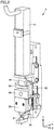
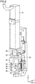
Fig. 1 schematically shows an application apparatus according to an embodiment. -
Fig. 2 schematically shows an application mechanism of the application apparatus shown inFig. 1 . -
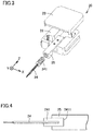
Fig. 3 schematically shows a configuration of an application needle holder shown inFig. 2 according to a first embodiment. -
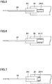
Fig. 4 is a schematic cross section of a first exemplary manner of attaching together an application needle, an application needle insertion material, and an application needle fixing plate shown inFig. 3 . -
Fig. 5 is a schematic cross section of a second exemplary manner of attaching together the application needle, the application needle insertion material, and the application needle fixing plate shown inFig. 3 . -
Fig. 6 is a schematic cross section of a third exemplary manner of attaching together the application needle, the application needle insertion material, and the application needle fixing plate shown inFig. 3 . -
Fig. 7 is a schematic cross section of a fourth exemplary manner of attaching together the application needle, the application needle insertion material, and the application needle fixing plate shown inFig. 3 . -
Fig. 8 schematically shows a base body of the application mechanism shown inFig. 2 . -
Fig. 9 is a schematic diagram also showing an application needle case to be attached to the application needle of the application needle holder ofFig. 3 . -
Fig. 10 is a schematic cross section of a first exemplary state before the application needle case is attached to the application needle member in the present embodiment. -
Fig. 11 is a schematic cross section of a second exemplary state before the application needle case is attached to the application needle member in the present embodiment. -
Fig. 12 is a schematic cross section of a third exemplary state before the application needle case is attached to the application needle member in the present embodiment. -
Fig. 13 is a schematic cross section of a fourth exemplary state before the application needle case is attached to the application needle member in the present embodiment. -
Fig. 14 is a schematic cross section of a first exemplary manner of attaching theFig. 10 application needle member and application needle case together. -
Fig. 15 is a schematic cross section of a second exemplary manner of attaching theFig. 11 application needle member and application needle case together. -
Fig. 16 is a schematic cross section of a third exemplary manner of attaching theFig. 12 application needle member and application needle case together. -
Fig. 17 is a schematic cross section of a fourth exemplary manner of attaching theFig. 13 application needle member and application needle case together. -
Fig. 18 schematically shows a configuration of an application needle holder according to a second embodiment. -
Fig. 19 is a schematic cross section of a manner of attaching together an application needle member and an application needle case shown inFig. 18 . -
Fig. 20 schematically shows a configuration of an application needle holder according to a third embodiment. -
Fig. 21 is a schematic cross section of a manner of attaching together an application needle member and an application needle case shown inFig. 20 . - Hereinafter, embodiments of the present invention will be described with reference to the drawings. In the figures, identical or equivalent components are identically denoted and will not be described redundantly.
-
Fig. 1 schematically shows an application apparatus according to the present embodiment. The application apparatus according to the present embodiment will be described with reference toFig. 1 . For the sake of convenience, directions X, Y and Z are introduced. Referring toFig. 1 , the application apparatus according to an embodiment of the present invention mainly comprises: a process chamber; a Y-axis table 2, an X-axis table 1, a Z-axis table 3, anapplication mechanism 4 as an application member, an observationoptical system 6, and a CCD camera 7 connected to observationoptical system 6, which are arranged inside the process chamber; and a control unit. The control unit includes amonitor 9, acontrol computer 10, and aconsole panel 8. - In the process chamber, Y-axis table 2 is placed above the floor of the process chamber. Y-axis table 2 is movable along the Y-axis. Specifically, a guide unit is placed on the lower surface of Y-axis table 2. The guide unit is slidably connected to a guide rail placed on the floor of the process chamber. A ball screw is connected to the lower surface of Y-axis table 2. The ball screw can be operated by a drive member such as a motor to cause Y-axis table 2 to move along the guide rail (along the Y-axis). Y-axis table 2 has an upper surface serving as a mount surface on which a
substrate 5, which is an object to be processed, is mounted. Accordingly, Y-axis table 2 functions as a holding table to hold an object to which a liquid material is applied, orsubstrate 5. - X-axis table 1 is placed above Y-axis table 2. X-axis table 1 is disposed on a structure placed over and extending across Y-axis table 2 along the X-axis. X-axis table 1 is provided with a moving body to which Z-axis table 3 is connected, and the moving body is disposed to be movable along the X-axis. The moving body is movable along the X-axis by means of a ball screw for example. X-axis table 1 is fixed to the floor of the process chamber via the aforementioned structure. Therefore, Y-axis table 2 is movable along the Y-axis with respect to X-axis table 1.
- On the moving body connected to X-axis table 1, Z-axis table 3 is placed as described above. To Z-axis table 3, observation
optical system 6 andapplication mechanism 4 are connected. Observationoptical system 6 is provided for observing an application position ofsubstrate 5 to which a material is applied. CCD camera 7 converts an observed image into an electrical signal. Z-axis table 3 holds observationoptical system 6 andapplication mechanism 4 so that they are movable along the Z-axis. -
Control computer 10 andconsole panel 8 for controlling Y-axis table 2, X-axis table 1, Z-axis table 3, observationoptical system 6, andapplication mechanism 4, as well asmonitor 9 associated withcontrol computer 10 are placed outside the process chamber.Monitor 9 displays image data converted by CCD camera 7, data output fromcontrol computer 10, and the like.Console panel 8 is used for entering instructions to controlcomputer 10. -
Fig. 2 schematically shows an application mechanism of the application apparatus shown inFig. 1 . Referring toFig. 2 ,application mechanism 4 of the present embodiment mainly includes aservomotor 41, acam 43, abearing 44 held in contact with a cam surface ofcam 43, acam coupling plate 45, amovable portion 46, amovable base 35 holding anapplication needle holder 20, and anapplication material container 21.Application needle holder 20 is detachably attachable tomovable base 35. In other words,movable base 35 as a base body detachably holdsapplication needle holder 20. - In
application mechanism 4,servo motor 41 is placed so that its central axis extends along the Z-axis shown inFig. 1 .Cam 43 is connected to a rotational shaft ofservo motor 41.Cam 43 is rotatable about the central axis ofservo motor 41.Cam 43 includes a central portion connected to the rotational shaft ofservo motor 41, and a flange portion connected to one end of the central portion. The flange portion has an upper surface (a surface facing servo motor 41) serving as a cam surface. This cam surface is formed in an annular shape along the outer periphery of the central portion, and is formed to slope so that the distance from the bottom surface of the flange portion to the cam surface varies. Specifically, the cam surface includes: an upper-end flat region (having a large thickness) where the distance from the bottom surface is the largest distance; a lower-end flat region located at a distance from the upper-end flat region; and a slope portion smoothly connecting the upper-end flat region and the lower-end flat region together. The lower-end flat region is a region (having a small thickness) where the distance from the bottom surface is the smallest distance. -
Bearing 44 is disposed to contact the cam surface ofcam 43.Cam coupling plate 45 is connected to bearing 44.Cam coupling plate 45 has one end connected to bearing 44 and the other, opposite end fixed tomovable portion 46.Movable base 35 as a base body is connected tomovable portion 46.Application needle holder 20 is placed onmovable base 35.Application needle holder 20 includesapplication needle 24.Application needle 24 can apply a liquid material to the object orsubstrate 5.Application needle 24 is disposed to protrude from the lower surface of application needle holder 20 (from the lower side opposite to the side whereservomotor 41 is located). Underapplication needle holder 20,application material container 21 is disposed.Application needle 24 is inserted inapplication material container 21 and thus held. - A fixing pin is fixed to
movable portion 46. Another fixing pin is fixed to a pedestal holdingservo motor 41. A spring is placed to connect one fixing pin to the other fixing pin. Onmovable portion 46, a force in the direction towardapplication material container 21 is exerted by the spring. The force exerted by the spring causes bearing 44 to be kept pressed against the cam surface ofcam 43. -
Movable portion 46 andmovable base 35 are connected to a linear guide placed on the pedestal that holdsservo motor 41, and are movable along the Z-axis. - In
application mechanism 4,servo motor 41 is driven to rotate the rotational shaft ofservo motor 41 and thereby rotatecam 43. As a result, the position along Z-axis of bearing 44 that is in contact with the cam surface ofcam 43 varies as the rotational shaft ofservo motor 41 rotates. As bearing 44 positionally varies along the Z-axis,movable portion 46 andmovable base 35 move along the Z-axis, andapplication needle 24 can thus be positionally changed along the Z-axis. -
Fig. 3 schematically shows a configuration of the application needle holder shown inFig. 2 according to the first embodiment. InFig. 3 , for the sake convenience, each member included in the application needle holder is shown in an exploded manner. Referring toFig. 3 ,application needle holder 20 mainly includes aholder base 22 and aholder lid 23 as a casing, and an applicationneedle fixing plate 25 as a fixing member to whichapplication needle 24 is fixed. Insideholder base 22, a recess is formed for accommodating applicationneedle fixing plate 25 withapplication needle 24 connected thereto. In other words, applicationneedle fixing plate 25 is disposed inside the casing composed ofholder base 22 andholder lid 23.Application needle 24 has a tip by which a liquid material is applied to an object, and an end portion opposite to the tip in a direction in whichapplication needle 24 extends (i.e., the direction Z shown inFig. 3 ) (that is, an end portion on the side of the bottom of application needle 24), and applicationneedle fixing plate 25 is fixed to the opposite end portion. Applicationneedle fixing plate 25 detachably fixesapplication needle 24. - More specifically, an application
needle insertion material 241 is attached to an end portion ofapplication needle 24 located on a side opposite, as seen in the direction in whichapplication needle 24 extends (i.e., the direction Z shown inFig. 3 ), to a side where the liquid material is applied to the object (that is, on the side of the bottom of application needle 24).Application needle 24 and applicationneedle insertion material 241 configure an application needle member. Applicationneedle insertion material 241 is a cap-shaped member attached to the end portion ofapplication needle 24 on the side of the bottom thereof. Applicationneedle insertion material 241 is a member formed so as to externally cover a surface of the bottom ofapplication needle 24. Applicationneedle insertion material 241 is for example a cylindrical member. Applicationneedle insertion material 241 has a hollow portion capable of accommodating a portion of the bottom ofapplication needle 24. The hollow portion is preferably cylindrically shaped, for example, so as to be fittable to the external shape ofapplication needle 24. The end portion of the bottom ofapplication needle 24 is inserted into the hollow portion, for example. In this state, applicationneedle insertion material 241 is attached toapplication needle 24. From a different point of view, the above-described application needle member is an application needle member capable of applying a liquid material to an object, and includesapplication needle 24 and applicationneedle insertion material 241.Application needle 24 includes a tip facing the object and a bottom located opposite to the tip. Applicationneedle insertion material 241 is attached to the bottom ofapplication needle 24. As will be described hereinafter, applicationneedle insertion material 241 is configured to be detachably attachable to applicationneedle fixing plate 25 serving as a fixing member. Further,application mechanism 4 as an application member shown inFig. 2 includesapplication needle holder 20 andmovable base 35 serving as a base body.Movable base 35 detachably holdsapplication needle holder 20.Application needle holder 20 includes: a main body portion includingholder base 22,holder lid 23 and applicationneedle fixing plate 25; and an application needle member includingapplication needle 24 and applicationneedle insertion material 241.Holder base 22 andholder lid 23 configure a casing. That is, the main body portion includes the casing and applicationneedle fixing plate 25 serving as a fixing member. Applicationneedle fixing plate 25 is disposed inside the casing. The application needle member includingapplication needle 24 and applicationneedle insertion material 241 is detachably attached to the main body portion. More specifically, applicationneedle insertion material 241 is detachably attached to applicationneedle fixing plate 25. - When application
needle insertion material 241 is cut along a cross section intersecting a direction in which it extends (i.e., a cross section along the XY plane inFig. 3 ), applicationneedle insertion material 241 preferably has a cross-sectional area sufficiently larger than that ofapplication needle 24. Applicationneedle insertion material 241 has an outer diameter sufficiently larger than the diameter ofapplication needle 24. - Application
needle insertion material 241 configuring the application needle member is detachably attached to applicationneedle fixing plate 25. That is, applicationneedle insertion material 241 is disposed such that at least a portion thereof is embedded in an opening of applicationneedle fixing plate 25. The opening is formed in an end portion of applicationneedle fixing plate 25. In that state, applicationneedle insertion material 241 is attached to applicationneedle fixing plate 25. That is, applicationneedle insertion material 241 and applicationneedle fixing plate 25 are fixed together such that an inner circumferential surface of the opening of applicationneedle fixing plate 25 is in contact with an external circumferential surface of applicationneedle insertion material 241. - Specifically, application
needle insertion material 241 is attached to applicationneedle fixing plate 25 in the following manner.Fig. 4 is a schematic cross section of a first exemplary manner of attaching together the application needle, application needle insertion material, and application needle fixing plate shown inFig. 3 . Referring toFig. 4 , in the first example, applicationneedle insertion material 241 and applicationneedle fixing plate 25 are press-fitted so that, at anattachment portion 2411 that is an interface where the inner circumferential surface of the opening of applicationneedle fixing plate 25 and the external circumferential surface of applicationneedle insertion material 241 contact each other, the external circumferential surface of applicationneedle insertion material 241 presses the inner circumferential surface of applicationneedle fixing plate 25 and thus causes frictional resistance, which allows applicationneedle insertion material 241 and applicationneedle fixing plate 25 to be attached together.Application needle 24 is fixed such thatapplication needle 24 has the bottom inserted into the opening formed in an end portion of applicationneedle insertion material 241. Any method can be used to fixapplication needle 24 to applicationneedle insertion material 241.Fig. 5 is a schematic cross section of a second exemplary manner of attaching together the application needle, application needle insertion material, and application needle fixing plate shown inFig. 3 . Referring toFig. 5 , in the second example, applicationneedle insertion material 241 and applicationneedle fixing plate 25 are attached together at ascrew portion 2412 as a male screw and a female screw are screwed together. That is, applicationneedle insertion material 241 shown inFig. 5 has an extension composed of a male screw or a female screw which is formed at one end of applicationneedle insertion material 241 opposite to the other end thereof havingapplication needle 24 fixed thereto and configuresscrew portion 2412. A small opening that receives the extension is formed at the bottom surface of the opening of applicationneedle fixing plate 25. A female screw or a male screw configuringscrew portion 2412 is formed on the internal circumferential surface of the small opening. -
Fig. 6 is a schematic cross section of a third exemplary manner of attaching together the application needle, application needle insertion material, and application needle fixing plate shown inFig. 3 . Referring toFig. 6 , in the third example, applicationneedle insertion material 241 and applicationneedle fixing plate 25 are attached together at aluer portion 2413 by a so-called luer lock system.Luer portion 2413 is a groove-shaped portion provided on an external surface of applicationneedle insertion material 241 and an internal surface of applicationneedle fixing plate 25.Luer portion 2413 on the external surface of applicationneedle insertion material 241 andluer portion 2413 formed on the internal circumferential surface of the opening of applicationneedle fixing plate 25 interfere with each other to attach applicationneedle insertion material 241 and applicationneedle fixing plate 25 together. That is, applicationneedle insertion material 241 shown inFig. 6 has an extension havingluer portion 2413 formed at one end of applicationneedle insertion material 241 opposite to the other end thereof havingapplication needle 24 fixed thereto.Luer portion 2413 is formed on the internal circumferential surface of the opening of applicationneedle fixing plate 25 at a portion facing the extension. -
Fig. 7 is a schematic cross section of a fourth exemplary manner of attaching together the application needle, application needle insertion material, and application needle fixing plate shown inFig. 3 . Referring toFig. 7 , in the fourth example, applicationneedle insertion material 241 and applicationneedle fixing plate 25 are attached together at alatch portion 2414 by a so-called rotational latch system.Latch portion 2414 is a groove-shaped portion provided on an external surface of applicationneedle insertion material 241 and an internal surface of applicationneedle fixing plate 25.Latch portion 2414 on the external surface of applicationneedle insertion material 241 andlatch portion 2414 formed on the internal circumferential surface of the opening of applicationneedle fixing plate 25 are relatively rotated about their rotation axis (i.e., a direction along the Z-axis inFig. 3 ) and thus engaged together to attach applicationneedle insertion material 241 and applicationneedle fixing plate 25 together. - As shown in
Figs. 4 to 7 , in the present embodiment, applicationneedle insertion material 241 and applicationneedle fixing plate 25 are attached together by any one selected from the group consisting of a press-fitting portion, a screw portion, a luer portion, and a latch portion. - In any of
Figs. 3 to 7 , applicationneedle insertion material 241 may be detachably attached toapplication needle 24. Note, however, that applicationneedle insertion material 241 may be attached toapplication needle 24 so as to be fixed thereto undetachably. When applicationneedle insertion material 241 is fixed toapplication needle 24 undetachably,application needle 24 can be easily detached from fixingplate 25 by detaching applicationneedle insertion material 241 from fixingplate 25. When applicationneedle insertion material 241 is detachably attached toapplication needle 24, it is done so preferably by press fitting, for example. When applicationneedle insertion material 241 is fixed toapplication needle 24 undetachably, it is preferably done so with an adhesive for example. - Application
needle insertion material 241 is preferably formed of a material different from that ofapplication needle 24. Specifically, for example,application needle 24 is preferably formed of a generally known stainless steel material. Applicationneedle insertion material 241 is preferably formed for example of generally known polyethylene resin, polypropylene resin, or other resin materials. -
Fig. 8 schematically shows the base body in the application mechanism shown inFig. 2 . Referring toFig. 8 , as has been described above, inapplication mechanism 4,application needle holder 20 is detachably attachable tomovable base 35. Specifically, a plurality of (e.g., two) magnets are disposed on a surface ofapplication needle holder 20 that is to face movable base 35 (i.e., a surface of holder base 22), although not shown. Further, as shown inFig. 8 , a plurality of magnets 33 (two magnets inFig. 8 ) are also disposed onmovable base 35. The magnets on the surface ofholder base 22 andmagnets 33 ofmovable base 35 shown inFig. 8 attract each other to enableapplication needle holder 20 to be placed onmovable base 35. Positionally adjusting the magnets on the surface ofholder base 22 andmagnets 33 ofmovable base 35 allowsapplication needle holder 20 to be accurately positioned whenapplication needle holder 20 is attracted tomovable base 35 by a magnetic force acting between the magnets ofholder base 22 andmagnets 33 ofmovable base 35. - For example, a reference surface of
application needle holder 20 in the direction Z can be pressed against a reference surface 34 ofmovable base 35, and a reference surface ofapplication needle holder 20 in the direction X can be pressed against a reference surface 36 ofmovable base 35. Such a state can be implemented for example by the following configuration: That is, a magnet ofapplication needle holder 20 and a magnet ofmovable base 35 that face each other whenapplication needle holder 20 is placed onmovable base 35 have their relative positions adjusted. Specifically,magnets 33 ofmovable base 35 are set to be positionally closer to reference surfaces 34 and 36 than the magnets ofapplication needle holder 20. This allows a magnetic force between the magnets on the surface ofapplication needle holder 20 andmagnets 33 ofmovable base 35 to exert a force to attractapplication needle holder 20 toward reference surfaces 34 and 36 (i.e., in a direction indicated inFig. 8 by an arrow). As a result,application needle holder 20 can be fixed tomovable base 35 with good reproducibility with high positional accuracy. -
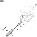
Fig. 9 is a schematic diagram also showing an application needle case to be attached toapplication needle 24 of the application needle holder shown inFig. 3 . InFig. 9 , for the sake of convenience, each member included in the application needle holder is shown in an exploded manner. Referring toFig. 9 ,application needle holder 20 includes anapplication needle case 242 in addition to the members shown inFig. 3 .Application needle case 242 is a cap-shaped member that coversapplication needle 24 and has an end portion attached to applicationneedle insertion material 241. -
Application needle case 242 is a member formed so as to externally cover a surface of a portion ofapplication needle 24 excluding a portion thereof covered with applicationneedle insertion material 241.Application needle case 242 has, for example, a cylindrical shape extending in the direction in whichapplication needle 24 extends. An end portion ofapplication needle case 242 that is located on the side of the tip ofapplication needle 24 is curved. Note, however, thatapplication needle case 242 may have a shape close to a cone having a diameter reduced toward the tip ofapplication needle 24. In any case,application needle case 242 can partially or entirely accommodateapplication needle 24. - When
application needle case 242 is cut along a cross section intersecting the direction in which it extends (i.e., a cross section along the XY plane inFig. 3 ),application needle case 242 preferably has an internal space accommodatingapplication needle 24 with a cross-sectional area sufficiently larger than that ofapplication needle 24. For example, the internal space accommodatingapplication needle 24 preferably has a width three times or more the diameter ofapplication needle 24.Application needle case 242 has an external shape sufficiently larger in thickness thanapplication needle 24. -
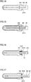
Application needle case 242 is detachably attachable toapplication needle 24. More specifically,application needle case 242 is detachably attachable to the application needle member composed ofapplication needle 24 and applicationneedle insertion material 241.Fig. 10 is a schematic cross section of a first exemplary state before the application needle case is attached to the application needle member in the present embodiment.Fig. 11 is a schematic cross section of a second exemplary state before the application needle case is attached to the application needle member in the present embodiment.Fig. 12 is a schematic cross section of a third exemplary state before the application needle case is attached to the application needle member in the present embodiment.Fig. 13 is a schematic cross section of a fourth exemplary state before the application needle case is attached to the application needle member in the present embodiment. Referring toFig. 10 , as shown in the first example, the state beforeapplication needle case 242 is attached to the application needle member composed ofapplication needle 24 and applicationneedle insertion material 241 is as follows: That is, whenapplication needle case 242 is attached to the application needle member,application needle case 242 coversapplication needle 24 from the side of the tip ofapplication needle 24 opposite to the bottom thereof attached to applicationneedle insertion material 241. Referring toFigs. 11, 12 and 13 , the second, third and fourth examples are basically similar toFig. 10 . In the first example shown inFig. 10 ,application needle case 242 has an open end portion brought into contact with and thus fixed to an external circumferential surface of applicationneedle insertion material 241, as will be described hereinafter.Application needle case 242 has the open end portion with a smooth inner circumferential surface and applicationneedle insertion material 241 has a smooth external circumferential surface. - In
Fig. 11 , ascrew portion 2415 is formed on a surface of applicationneedle insertion material 241 at a portion accommodated inapplication needle case 242. Further, inFig. 11 , ascrew portion 2421 is formed on the inner circumferential surface ofapplication needle case 242 at a region on the side of the open end portion. One ofscrew portion 2415 andscrew portion 2421 is a male screw, and the other is a female screw. - In
Fig. 12 , alure portion 2416 is formed on a surface of applicationneedle insertion material 241 at a portion accommodated inapplication needle case 242. Further, inFig. 12 , alure portion 2423 is formed on the inner circumferential surface ofapplication needle case 242 at a region on the side of the open end portion. - In
Fig. 13 , alatch portion 2417 is formed on a surface of applicationneedle insertion material 241 at a portion accommodated inapplication needle case 242. Further, inFig. 12 , alatch portion 2424 is formed on the inner circumferential surface ofapplication needle case 242 at a region on the side of the open end portion. -
Fig. 14 is a schematic cross section of a first exemplary manner of attaching theFig. 10 application needle member and application needle case together.Fig. 15 is a schematic cross section of a second exemplary manner of attaching theFig. 11 application needle member and application needle case together.Fig. 16 is a schematic cross section of a third exemplary manner of attaching theFig. 12 application needle member and application needle case together.Fig. 17 is a schematic cross section of a fourth exemplary manner of attaching theFig. 13 application needle member and application needle case together. Referring toFigs. 14 to 17 ,application needle case 242 of each ofFigs. 10 to 13 is attached to applicationneedle insertion material 241 configuring an application needle member, as shown inFigs. 14 to 17. Figs. 14 to 17 show a structure in which an application needle member andapplication needle case 242, which serve as an application needle member assembly, are attached together.Application needle case 242 is attached to the application needle member while accommodatingapplication needle 24 of the application needle member therein. Specifically, referring toFig. 14 , in the first example,application needle case 242 andapplication needle 24 are attached together at anattachment portion 2418 by press fitting. An end portion of applicationneedle insertion material 241 on the side ofapplication needle 24 is press-fitted into the open end portion ofapplication needle case 242. The inner circumferential surface of the open end portion ofapplication needle case 242 and the external circumferential surface of applicationneedle insertion material 241 at the end portion thereof on the side ofapplication needle 24 are in contact with each other. A frictional force is generated at a press-fitting portion that is an interface where the inner circumferential surface of the open end portion ofapplication needle case 242 and the external circumferential surface of applicationneedle insertion material 241 at the end portion thereof on the side ofapplication needle 24 contact each other. - Referring to
Fig. 15 , in the second example,application needle case 242 and applicationneedle insertion material 241 are attached together at ascrew portion 2419 formed by screwing theFig. 11 screw portion 2415 into theFig. 11 screw portion 2421. - Referring to
Fig. 16 , in the third example,application needle case 242 and applicationneedle insertion material 241 are attached together in a so-called luer lock system as theFig. 12 luer portion 2416 andluer portion 2423 mesh with each other. This manner is similar toluer portion 2413 shown inFig. 6 . That is, inFig. 6 , a portion corresponding toluer portion 2416 inFig. 12 and a portion corresponding toluer portion 2423 inFig. 12 are collectively shown asluer portion 2413. - Referring to
Fig. 17 , in the fourth example,application needle case 242 and applicationneedle insertion material 241 are attached together in a so-called rotational latch system aslatch portions Fig. 13 mesh with each other. This manner is similar to latchportion 2414 shown inFig. 7 . That is, inFig. 7 , a portion corresponding to latchportion 2417 inFig. 13 and a portion corresponding to latchportion 2424 inFig. 13 are collectively shown aslatch portion 2414. - As shown in
Figs. 14 to 17 , in the present embodiment, applicationneedle insertion material 241 is configured such thatapplication needle case 242accommodating application needle 24 therein is attached thereto. Applicationneedle insertion material 241 andapplication needle case 242 are attached together by any one selected from the group consisting of a press-fitting portion, a screw portion, a luer portion, and a latch portion. Further, as shown inFigs. 4 to 7 and10 to 17 , applicationneedle insertion material 241 includes a first attachment portion (attachment portion 2411 ofFig. 4 ,screw portion 2412 ofFig. 5 ,luer portion 2413 ofFig. 6 , andlatch portion 2414 ofFig. 7 ) allowing applicationneedle insertion material 241 to be detachably attached to applicationneedle fixing plate 25 serving as a fixing member, and a second attachment portion (attachment portion 2418 ofFig. 14 ,screw portion 2419 ofFig. 15 ,luer portion 2413 ofFig. 16 , andlatch portion 2414 ofFig. 17 ) allowingapplication needle case 242 to be attached to applicationneedle insertion material 241. This ensures attachment between applicationneedle insertion material 241 and another member. - In the states shown in
Figs. 14 to 17 , the application needle member composed ofapplication needle 24 and applicationneedle insertion material 241 withapplication needle case 242 attached thereto may be sterilized. For example, the application needle member is sterilized when it is used for a medical purpose or in a biochemical experiment, in particular. In that case, the sterilizing operation is performed using EOG (ethylene oxide gas), gamma rays, electron beams, or the like. Specifically, initially, the application needle member withapplication needle case 242 attached thereto is individually packaged. In this state, EOG is introduced into the individual package, and the individual package is sealed. Alternatively, the individually packaged application needle member withapplication needle case 242 attached thereto is exposed to gamma rays or electron beams. In the case of sterilization with EOG, the individual package may partially or entirely be composed of a member such as film or fiber which is permeable to a sterilizing gas such as EOG. In order to allow the sterilizing gas to come into contact withapplication needle 24 located insideapplication needle case 242, it is preferable thatapplication needle case 242 is previously provided with a hole for permeation of gas. - Normally, the application needle member composed of
application needle 24 and applicationneedle insertion material 241 is sold withapplication needle case 242 attached to coverapplication needle 24, as shown inFigs. 14 to 17 . The application needle member sold in this state is attached to applicationneedle fixing plate 25 at a customer's end. The attachment is done in a manner shown in any one ofFigs. 4 to 7 . The application needle member attached to applicationneedle fixing plate 25 is used withapplication needle case 242 removed therefrom. - The present embodiment has a function and effect, as described hereinafter. An application needle member comprising
application needle 24 and applicationneedle insertion material 241 according to the present embodiment is fixed to applicationneedle fixing plate 25 ofapplication needle holder 20. In other words, applicationneedle fixing plate 25 is disposed inapplication needle holder 20 inside a casing composed ofholder base 22 andholder lid 23 according to the present embodiment.Application needle 24 is detachably attached to applicationneedle fixing plate 25. That is, the application needle member includingapplication needle 24 can be removed from applicationneedle fixing plate 25 and replaced as desired. Therefore, for example, when a plurality of different types of liquid materials are applied, the application needle member can be easily replaced for each liquid material. Therefore, it is no longer necessary to apply a plurality of types of liquid materials by using thesame application needle 24. This can suppress contamination caused when a liquid material to be applied is mixed with another type of liquid material as a plurality of types of liquid materials are applied using thesame application needle 24. Further, a cleaning operation of manually wiping a liquid material offapplication needle 24 with a solvent such as acetone in advance can be dispensed with. This can improve the efficiency of an operation of application usingapplication needle 24. - Note that application
needle insertion material 241 is attached toapplication needle 24, and applicationneedle insertion material 241 is detachably attached to applicationneedle fixing plate 25. Applicationneedle insertion material 241 and applicationneedle fixing plate 25 are attached together by any one selected from the group consisting of attachment portion 2411 (seeFig. 4 ) that is a press fitting portion attached by press fitting, screw portion 2412 (seeFig. 5 ), luer portion 2413 (seeFig. 6 ), and latch portion 2414 (seeFig. 7 ). Therefore,application needle 24 can be easily removed from applicationneedle fixing plate 25 and thus replaced. - In the present embodiment,
application needle case 242 can be attached to the application needle member so as to coverapplication needle 24. Herein,application needle case 242 is attached to applicationneedle insertion material 241 configuring the application needle member. Applicationneedle insertion material 241 andapplication needle case 242 are attached together by any one selected from the group consisting ofattachment portion 2418 that is a press fitting portion (seeFig. 14 ), screw portion 2419 (seeFig. 15 ),luer portions 2416 and 2423 (seeFigs. 12 and16 ), and latchportions 2417 and 2424 (seeFigs. 13 and17 ). In replacing an application needle member includingapplication needle 24 with another application needle member includingapplication needle 24, contamination caused as a foreign matter adheres to a surface ofapplication needle 24 of the other application needle member can be suppressed. In addition, the application needle member can be replaced in a state in whichapplication needle 24 is protected byapplication needle case 242. This can suppress an accident in which an operator accidentally pricks his/her hand or the like with the tip ofapplication needle 24 when the operator replaces the application needle member with another. -
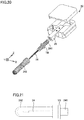
Fig. 18 schematically shows a configuration of an application needle holder according to a second embodiment.Fig. 19 schematically shows how the application needle member and the application needle case shown inFig. 18 are attached together. In contrast to the schematic cross sections ofFigs. 14 to 17 ,Fig. 19 showsapplication needle case 242 with its interior indicated by a dotted line as if it were seen through. - Referring to
Figs. 18 and 19 ,application needle holder 20 according to the present embodiment has basically the same configuration as that ofapplication needle holder 20 according to the first embodiment. Applicationneedle insertion material 241 detachably attached to applicationneedle fixing plate 25 andapplication needle case 242 attached to applicationneedle insertion material 241 are also basically the same in configuration as those in the first embodiment. Accordingly, identical components are identically denoted and any feature shared with the first embodiment will not be described repeatedly. - Note, however, that, as shown in
Figs. 18 and 19 , in the present embodiment, applicationneedle insertion material 241 has at least a portion having a surface colored to provide a colored portion CLD. In this regard, the present embodiment is different in configuration from the first embodiment, which does not include such a colored portion CLD. The region of applicationneedle insertion material 241 in which colored portion CLD is provided is a region to be inserted into the opening of applicationneedle fixing plate 25 and fixed therein. Colored portion CLD is provided to applicationneedle insertion material 241 on a surface of a region on a side opposite, as seen in a direction in whichapplication needle 24 extends, to a side where a liquid material is applied, i.e., on a surface of a region on the side of the bottom ofapplication needle 24. InFig. 19 , a region of the surface of applicationneedle insertion material 241 other than colored portion CLD is a non-colored portion NCLD. Colored portion CLD may have any color that is different from that of non-colored portion NCLD. Colored portion CLD may be a colored resin layer coating a surface of applicationneedle insertion material 241, or may be formed by winding a colored resin tape on applicationneedle insertion material 241. - The present embodiment has a function and effect, as described hereinafter. The present embodiment has a function and effect similar to those of the first embodiment and the following function and effect:
- In the present embodiment, application
needle insertion material 241 has at least a portion provided with colored portion CLD, as has been described above. That is, colored portion CLD is provided to applicationneedle insertion material 241 on a surface of a region relatively close to applicationneedle fixing plate 25. Therefore, applicationneedle insertion material 241 is disposed such that a portion thereof including colored portion CLD, in particular, is embedded in the opening of applicationneedle fixing plate 25. For example, colored portion CLD is attached through a press-fitting step to applicationneedle fixing plate 25 atattachment portion 2411 as shown inFig. 4 . As a result, the user ofapplication needle holder 20 can push applicationneedle insertion material 241 into the opening of applicationneedle fixing plate 25 so that applicationneedle insertion material 241 has colored portion CLD entirely inserted into the opening of applicationneedle fixing plate 25 to ensure that applicationneedle insertion material 241 is fixed to applicationneedle fixing plate 25. -
Fig. 20 schematically shows a configuration of an application needle holder according to a third embodiment.Fig. 21 schematically shows how the application needle member and the application needle case inFig. 20 are attached together. As well asFig. 19 ,Fig. 21 showsapplication needle case 242 with its interior indicated by a dotted line as if it were seen through. - Referring to
Figs. 20 and 21 ,application needle holder 20 according to the present embodiment has basically the same configuration as that ofapplication needle holder 20 according to the first embodiment. Applicationneedle insertion material 241 detachably attached to applicationneedle fixing plate 25 andapplication needle case 242 attached to applicationneedle insertion material 241 are also basically the same in configuration as those in the first embodiment. Accordingly, identical components are identically denoted and any feature shared with the first embodiment will not be described repeatedly. - It should be noted, however, that, as shown in
Figs.20 and 21 , in the present embodiment, applicationneedle insertion material 241 has a portion provided with a flange portion TB that is larger in a size, that is, a diameter for example, (in the XY plane) intersecting a direction in which applicationneedle insertion material 241 extends (i.e., the direction Z) than the remainder of applicationneedle insertion material 241. In this regard, the present embodiment is different in configuration from the first and second embodiments that do not have such a flange portion TB. - Flange portion TB has a diameter (or a distance from its center) in cross section preferably 1.5 times or more and 2 times or less, more preferably 1.6 times or more and 1.9 times or less, that in cross section of a region of application
needle insertion material 241 excluding flange portion TB. Flange portion TB at least has only to have a maximum width larger than that of the opening of applicationneedle fixing plate 25. The maximum width of flange portion TB may be larger or smaller than a size (a length of one side, or a diameter) of applicationneedle fixing plate 25 in the XY plane. - Flange portion TB may be disposed at a position including a central portion of application
needle insertion material 241 in the direction in which applicationneedle insertion material 241 extends (or the direction Z inFig. 20 ). Note, however, that this is not exclusive, and flange portion TB may be formed for example to be disposed in a region closer to the tip ofapplication needle 24 than the central portion of applicationneedle insertion material 241 in the direction in which applicationneedle insertion material 241 extends. - The present embodiment has a function and effect, as described hereinafter. The present embodiment has a function and effect similar to those of the first embodiment and the following function and effect:
- In the present embodiment, application
needle insertion material 241 has at least a portion provided with flange portion TB, as has been described above. Accordingly, for example, applicationneedle insertion material 241 can be attached to applicationneedle fixing plate 25 such that a region of applicationneedle insertion material 241 opposite, as seen at flange portion TB, to an end portion of applicationneedle insertion material 241 havingapplication needle 24 connected thereto is entirely accommodated in the opening of applicationneedle fixing plate 25. That is, flange portion TB functions as a stopper when applicationneedle insertion material 241 is fixed to applicationneedle fixing plate 25. When presence of flange portion TB is compared with absence thereof, the former can suppress variation in length along the Z-axis of a region of applicationneedle insertion material 241 inserted into the opening of applicationneedle fixing plate 25. - Note that the features of the above-described embodiments (or examples) may be combined as appropriate within a consistent range in the art. For example, the third embodiment may also be provided with colored portion CLD on a surface of application
needle insertion material 241 on a side opposite to the tip ofapplication needle 24, as seen at flange portion TB. As well as the first embodiment, the second and third embodiments have only to attach applicationneedle insertion material 241 and applicationneedle fixing plate 25 together by any one selected from the group consisting of a press-fitting portion, a screw portion, a luer portion, and a latch portion. Further, as well as the first embodiment, the second and third embodiments have only to attach applicationneedle insertion material 241 andapplication needle case 242 together by any one selected from the group consisting of a press-fitting portion, a screw portion, a luer portion, and a latch portion. - The embodiments disclosed herein should be considered as illustrative in any respect and not restrictive. The scope of the present invention is defined by the terms of the claims, rather than the above description, and is intended to include any modifications within the meaning and scope equivalent to the terms of the claims.
- 1 X-axis table, 2 Y-axis table, 3 Z-axis table, 4 application mechanism, 5 substrate, 6 observation optical system, 7 CCD camera, 8 console panel, 9 monitor, 10 control computer, 20 application needle holder, 21 application material container, 22 holder base, 23 holder lid, 24 application needle, 25 application needle fixing plate, 33 magnet, 34, 36 reference surface, 35 movable base, 41 servomotor, 43 cam, 44 bearing, 45 cam coupling plate, 46 movable portion, 241 application needle insertion material, 242 application needle case, 2411 attachment portion, 2412, 2415, 2419, 2421 screw portion, 2413, 2416, 2423 luer portion, 2414, 2417, 2424 latch portion, CLD colored portion, NCLD non-colored portion.
Claims (9)
- An application needle member capable of applying a liquid material to an object, comprising:an application needle including a tip facing the object and a bottom opposite to the tip; andan application needle insertion material attached to the bottom of the application needle,the application needle insertion material being configured to be detachably attachable to a fixing member.
- The application needle member according to claim 1, wherein the application needle insertion material is configured to allow an application needle case to be attached thereto to accommodate the application needle therein.
- The application needle member according to claim 2, wherein the application needle insertion material includes a first attachment portion allowing the application needle insertion material to be detachably attached to the fixing member and a second attachment portion allowing the application needle case to be attached to the application needle insertion material.
- An application needle member assembly comprising:an application needle member according to claim 2 or 3; andthe application needle case attached to the application needle member while accommodating the application needle therein.
- An application member comprising:an application needle holder; anda base body that detachably holds the application needle holder, the application needle holder includinga main body portion andan application needle member detachably attached to the main body portion.
- The application member according to claim 5, wherein
the main body portion includes a casing and a fixing member disposed inside the casing,
the application needle member includes an application needle including a tip and a bottom opposite to the tip, and an application needle insertion material attached to the bottom of the application needle, and
the application needle insertion material is detachably attached to the fixing member. - The application member according to claim 6, wherein the application needle insertion material and the fixing member are attached together by any one selected from the group consisting of a press-fitting portion, a screw portion, a luer portion, and a latch portion.
- The application member according to any one of claims 5 to 7, wherein the application needle member allows an application needle case to be attached thereto.
- An application apparatus comprising:an application member according to any one of claims 5 to 8; anda holding table to hold an object to which a liquid material is applied with the application needle member.
Applications Claiming Priority (2)
| Application Number | Priority Date | Filing Date | Title |
|---|---|---|---|
| JP2018162874A JP7164997B2 (en) | 2018-08-31 | 2018-08-31 | Application needle member, application needle member assembly, application member, and application device |
| PCT/JP2019/032628 WO2020045187A1 (en) | 2018-08-31 | 2019-08-21 | Application needle member, application needle member assembly, application member and application device |
Publications (2)
| Publication Number | Publication Date |
|---|---|
| EP3845316A1 true EP3845316A1 (en) | 2021-07-07 |
| EP3845316A4 EP3845316A4 (en) | 2022-05-18 |
Family
ID=69644404
Family Applications (1)
| Application Number | Title | Priority Date | Filing Date |
|---|---|---|---|
| EP19854623.6A Pending EP3845316A4 (en) | 2018-08-31 | 2019-08-21 | APPLICATION NEEDLE COMPONENT, APPLICATION NEEDLE ASSEMBLY, APPLICATION COMPONENT AND APPLICATION DEVICE |
Country Status (5)
| Country | Link |
|---|---|
| US (1) | US11654450B2 (en) |
| EP (1) | EP3845316A4 (en) |
| JP (1) | JP7164997B2 (en) |
| CN (1) | CN112638543A (en) |
| WO (1) | WO2020045187A1 (en) |
Cited By (1)
| Publication number | Priority date | Publication date | Assignee | Title |
|---|---|---|---|---|
| WO2023072624A1 (en) * | 2021-10-28 | 2023-05-04 | Focke & Co. (Gmbh & Co. Kg) | Device for applying a preferably heated adhesive or (hot) glue |
Families Citing this family (3)
| Publication number | Priority date | Publication date | Assignee | Title |
|---|---|---|---|---|
| FR3113848B1 (en) * | 2020-09-07 | 2023-06-16 | Exel Ind | Device for applying a product, machine comprising such a device and method for controlling such a machine |
| JP7621134B2 (en) | 2021-02-25 | 2025-01-24 | Ntn株式会社 | Coating mechanism and coating device |
| CN113714043A (en) * | 2021-10-09 | 2021-11-30 | 常州天宇宏图电子有限公司 | Two-way deep hole adhesive deposite device |
Family Cites Families (17)
| Publication number | Priority date | Publication date | Assignee | Title |
|---|---|---|---|---|
| US5598973A (en) * | 1994-10-31 | 1997-02-04 | Weston; Colin K. | Fluid flow control device |
| US5934520A (en) * | 1997-11-03 | 1999-08-10 | Nordson Corporation | Liquid dispensing device |
| CA2231383A1 (en) * | 1998-04-16 | 1999-10-16 | Silhouet Tone Appareils De Beaute Ltee | Combined handle, needle head assembly and protective cover for use in a hair removal electrolysis apparatus |
| US6715506B1 (en) * | 1998-12-28 | 2004-04-06 | Musashi Engineering, Inc. | Method and device for injecting a fixed quantity of liquid |
| US6226068B1 (en) * | 1999-08-27 | 2001-05-01 | Amphenol Corporation | Self-locking bayonet coupling mechanism |
| MXPA03010697A (en) * | 2001-05-21 | 2005-03-07 | Colder Prod Co | Connector apparatus and method for connecting the same for controlling fluid dispensing. |
| JP4162086B2 (en) | 2003-08-26 | 2008-10-08 | Tdk株式会社 | Liquid material application method |
| JP4890024B2 (en) | 2005-12-27 | 2012-03-07 | Ntn株式会社 | Application needle fixing method, liquid material application mechanism and defect correction apparatus using the same |
| JP2007244671A (en) | 2006-03-16 | 2007-09-27 | Fujifilm Corp | Blood collection needle, injection needle, winged needle, inspection kit and blood collection kit |
| JP2008286370A (en) * | 2007-05-21 | 2008-11-27 | Denso Corp | Piping joint and piping joint device |
| US20120074001A1 (en) | 2009-01-12 | 2012-03-29 | Aktivpak, Inc. | Packaged products, inserts and compartments for aseptic mixing of substances, along with methods for use therewith |
| EP2582470B1 (en) * | 2010-06-15 | 2020-09-09 | 3M Innovative Properties Company | Distribution manifold with multiple dispensing needles |
| CN202590066U (en) * | 2012-02-09 | 2012-12-12 | 张亚平 | Antithrombotic anticoagulant type safe indwelling needle |
| JP6381902B2 (en) * | 2013-12-13 | 2018-08-29 | Ntn株式会社 | Application needle holder |
| US9855577B1 (en) * | 2014-01-23 | 2018-01-02 | Sio2 Medical Products, Inc. | Needle siliconization with controlled positive pressure gas flow |
| CN104668126A (en) * | 2015-01-23 | 2015-06-03 | 常州高凯精密机械有限公司 | Precision spraying valve |
| US11628257B2 (en) | 2016-07-11 | 2023-04-18 | Becton Dickinson France | Method for reducing an amount of subvisible particles in a pharmaceutical composition |
-
2018
- 2018-08-31 JP JP2018162874A patent/JP7164997B2/en active Active
-
2019
- 2019-08-21 EP EP19854623.6A patent/EP3845316A4/en active Pending
- 2019-08-21 US US17/265,159 patent/US11654450B2/en active Active
- 2019-08-21 WO PCT/JP2019/032628 patent/WO2020045187A1/en not_active Ceased
- 2019-08-21 CN CN201980056204.8A patent/CN112638543A/en active Pending
Cited By (1)
| Publication number | Priority date | Publication date | Assignee | Title |
|---|---|---|---|---|
| WO2023072624A1 (en) * | 2021-10-28 | 2023-05-04 | Focke & Co. (Gmbh & Co. Kg) | Device for applying a preferably heated adhesive or (hot) glue |
Also Published As
| Publication number | Publication date |
|---|---|
| CN112638543A (en) | 2021-04-09 |
| JP2020032389A (en) | 2020-03-05 |
| JP7164997B2 (en) | 2022-11-02 |
| US20210299694A1 (en) | 2021-09-30 |
| US11654450B2 (en) | 2023-05-23 |
| WO2020045187A1 (en) | 2020-03-05 |
| EP3845316A4 (en) | 2022-05-18 |
Similar Documents
| Publication | Publication Date | Title |
|---|---|---|
| US11654450B2 (en) | Application needle member, application needle member assembly, application member, and application apparatus | |
| JP6691163B2 (en) | Endoscope cap | |
| EP3311742A1 (en) | Blood collector | |
| JP2019195667A (en) | Safety device for prefilled syringes, comprising anti-triggering mechanism | |
| EP3871602B1 (en) | Medical system and method of sterility testing the medical system | |
| CN115135417B (en) | Injector for electric external piston type pipettor | |
| DE202012013761U1 (en) | analyte sensor | |
| EP3727130A1 (en) | Medical system and method of manufacturing thereof | |
| KR20220088890A (en) | Electric positive displacement pipette | |
| TW201711757A (en) | Coating unit and coating device using same | |
| KR20220088895A (en) | Positive Displacement Pipette Syringe Identification System | |
| EP3590607B1 (en) | Liquid application unit and liquid application apparatus | |
| US11007517B2 (en) | Sub-one microliter pipette | |
| EP4299195A1 (en) | Coating mechanism and coating apparatus | |
| CN115135416B (en) | Syringe piston gripping mechanism of electric external piston pipette | |
| US11730540B2 (en) | Catheter kit | |
| JP2024034939A (en) | Coating member and coating device | |
| EP4119238A1 (en) | Liquid material application unit, liquid material application device, and liquid material application method | |
| CN114786817B (en) | Electric external piston type distribution method | |
| CN120464476B (en) | Flexible and adaptable probe assembly, cell manipulation system, and probe reagent loading method | |
| US12549910B2 (en) | Vertical drilling guide and flatness measuring device for bone conduction implant | |
| US11389243B2 (en) | Optical measurement device, catheter kit, and optical measurement method | |
| WO2020022449A1 (en) | Coating needle holder, coating member, coating device, and coating method | |
| JP2023092727A (en) | Support unit, support body, and ionization method |
Legal Events
| Date | Code | Title | Description |
|---|---|---|---|
| STAA | Information on the status of an ep patent application or granted ep patent |
Free format text: STATUS: THE INTERNATIONAL PUBLICATION HAS BEEN MADE |
|
| STAA | Information on the status of an ep patent application or granted ep patent |
Free format text: STATUS: REQUEST FOR EXAMINATION WAS MADE |
|
| PUAI | Public reference made under article 153(3) epc to a published international application that has entered the european phase |
Free format text: ORIGINAL CODE: 0009012 |
|
| 17P | Request for examination filed |
Effective date: 20210301 |
|
| AK | Designated contracting states |
Kind code of ref document: A1 Designated state(s): AL AT BE BG CH CY CZ DE DK EE ES FI FR GB GR HR HU IE IS IT LI LT LU LV MC MK MT NL NO PL PT RO RS SE SI SK SM TR |
|
| DAV | Request for validation of the european patent (deleted) | ||
| DAX | Request for extension of the european patent (deleted) | ||
| A4 | Supplementary search report drawn up and despatched |
Effective date: 20220414 |
|
| RIC1 | Information provided on ipc code assigned before grant |
Ipc: H05K 3/12 20060101ALI20220408BHEP Ipc: B05C 11/10 20060101ALI20220408BHEP Ipc: B05C 1/02 20060101AFI20220408BHEP |
|
| STAA | Information on the status of an ep patent application or granted ep patent |
Free format text: STATUS: EXAMINATION IS IN PROGRESS |
|
| 17Q | First examination report despatched |
Effective date: 20240730 |
|
| GRAP | Despatch of communication of intention to grant a patent |
Free format text: ORIGINAL CODE: EPIDOSNIGR1 |
|
| STAA | Information on the status of an ep patent application or granted ep patent |
Free format text: STATUS: GRANT OF PATENT IS INTENDED |
|
| INTG | Intention to grant announced |
Effective date: 20260408 |