EP3845300A1 - Apparatus and process for producing a filter element - Google Patents
Apparatus and process for producing a filter element Download PDFInfo
- Publication number
- EP3845300A1 EP3845300A1 EP19220173.9A EP19220173A EP3845300A1 EP 3845300 A1 EP3845300 A1 EP 3845300A1 EP 19220173 A EP19220173 A EP 19220173A EP 3845300 A1 EP3845300 A1 EP 3845300A1
- Authority
- EP
- European Patent Office
- Prior art keywords
- hollow fiber
- fiber membranes
- disc
- picker arm
- heated metal
- Prior art date
- Legal status (The legal status is an assumption and is not a legal conclusion. Google has not performed a legal analysis and makes no representation as to the accuracy of the status listed.)
- Granted
Links
Images

Classifications
-
- B—PERFORMING OPERATIONS; TRANSPORTING
- B01—PHYSICAL OR CHEMICAL PROCESSES OR APPARATUS IN GENERAL
- B01D—SEPARATION
- B01D63/00—Apparatus in general for separation processes using semi-permeable membranes
- B01D63/02—Hollow fibre modules
- B01D63/021—Manufacturing thereof
-
- B—PERFORMING OPERATIONS; TRANSPORTING
- B29—WORKING OF PLASTICS; WORKING OF SUBSTANCES IN A PLASTIC STATE IN GENERAL
- B29C—SHAPING OR JOINING OF PLASTICS; SHAPING OF MATERIAL IN A PLASTIC STATE, NOT OTHERWISE PROVIDED FOR; AFTER-TREATMENT OF THE SHAPED PRODUCTS, e.g. REPAIRING
- B29C65/00—Joining or sealing of preformed parts, e.g. welding of plastics materials; Apparatus therefor
- B29C65/02—Joining or sealing of preformed parts, e.g. welding of plastics materials; Apparatus therefor by heating, with or without pressure
- B29C65/18—Joining or sealing of preformed parts, e.g. welding of plastics materials; Apparatus therefor by heating, with or without pressure using heated tools
-
- B—PERFORMING OPERATIONS; TRANSPORTING
- B29—WORKING OF PLASTICS; WORKING OF SUBSTANCES IN A PLASTIC STATE IN GENERAL
- B29C—SHAPING OR JOINING OF PLASTICS; SHAPING OF MATERIAL IN A PLASTIC STATE, NOT OTHERWISE PROVIDED FOR; AFTER-TREATMENT OF THE SHAPED PRODUCTS, e.g. REPAIRING
- B29C65/00—Joining or sealing of preformed parts, e.g. welding of plastics materials; Apparatus therefor
- B29C65/78—Means for handling the parts to be joined, e.g. for making containers or hollow articles, e.g. means for handling sheets, plates, web-like materials, tubular articles, hollow articles or elements to be joined therewith; Means for discharging the joined articles from the joining apparatus
- B29C65/7841—Holding or clamping means for handling purposes
-
- B—PERFORMING OPERATIONS; TRANSPORTING
- B29—WORKING OF PLASTICS; WORKING OF SUBSTANCES IN A PLASTIC STATE IN GENERAL
- B29C—SHAPING OR JOINING OF PLASTICS; SHAPING OF MATERIAL IN A PLASTIC STATE, NOT OTHERWISE PROVIDED FOR; AFTER-TREATMENT OF THE SHAPED PRODUCTS, e.g. REPAIRING
- B29C65/00—Joining or sealing of preformed parts, e.g. welding of plastics materials; Apparatus therefor
- B29C65/78—Means for handling the parts to be joined, e.g. for making containers or hollow articles, e.g. means for handling sheets, plates, web-like materials, tubular articles, hollow articles or elements to be joined therewith; Means for discharging the joined articles from the joining apparatus
- B29C65/7841—Holding or clamping means for handling purposes
- B29C65/7847—Holding or clamping means for handling purposes using vacuum to hold at least one of the parts to be joined
-
- B—PERFORMING OPERATIONS; TRANSPORTING
- B29—WORKING OF PLASTICS; WORKING OF SUBSTANCES IN A PLASTIC STATE IN GENERAL
- B29C—SHAPING OR JOINING OF PLASTICS; SHAPING OF MATERIAL IN A PLASTIC STATE, NOT OTHERWISE PROVIDED FOR; AFTER-TREATMENT OF THE SHAPED PRODUCTS, e.g. REPAIRING
- B29C65/00—Joining or sealing of preformed parts, e.g. welding of plastics materials; Apparatus therefor
- B29C65/78—Means for handling the parts to be joined, e.g. for making containers or hollow articles, e.g. means for handling sheets, plates, web-like materials, tubular articles, hollow articles or elements to be joined therewith; Means for discharging the joined articles from the joining apparatus
- B29C65/7858—Means for handling the parts to be joined, e.g. for making containers or hollow articles, e.g. means for handling sheets, plates, web-like materials, tubular articles, hollow articles or elements to be joined therewith; Means for discharging the joined articles from the joining apparatus characterised by the feeding movement of the parts to be joined
- B29C65/7876—Means for handling the parts to be joined, e.g. for making containers or hollow articles, e.g. means for handling sheets, plates, web-like materials, tubular articles, hollow articles or elements to be joined therewith; Means for discharging the joined articles from the joining apparatus characterised by the feeding movement of the parts to be joined oscillating around an axis
-
- B—PERFORMING OPERATIONS; TRANSPORTING
- B29—WORKING OF PLASTICS; WORKING OF SUBSTANCES IN A PLASTIC STATE IN GENERAL
- B29C—SHAPING OR JOINING OF PLASTICS; SHAPING OF MATERIAL IN A PLASTIC STATE, NOT OTHERWISE PROVIDED FOR; AFTER-TREATMENT OF THE SHAPED PRODUCTS, e.g. REPAIRING
- B29C66/00—General aspects of processes or apparatus for joining preformed parts
- B29C66/01—General aspects dealing with the joint area or with the area to be joined
- B29C66/02—Preparation of the material, in the area to be joined, prior to joining or welding
- B29C66/022—Mechanical pre-treatments, e.g. reshaping
- B29C66/0222—Mechanical pre-treatments, e.g. reshaping without removal of material, e.g. cleaning by air blowing or using brushes
-
- B—PERFORMING OPERATIONS; TRANSPORTING
- B29—WORKING OF PLASTICS; WORKING OF SUBSTANCES IN A PLASTIC STATE IN GENERAL
- B29C—SHAPING OR JOINING OF PLASTICS; SHAPING OF MATERIAL IN A PLASTIC STATE, NOT OTHERWISE PROVIDED FOR; AFTER-TREATMENT OF THE SHAPED PRODUCTS, e.g. REPAIRING
- B29C66/00—General aspects of processes or apparatus for joining preformed parts
- B29C66/01—General aspects dealing with the joint area or with the area to be joined
- B29C66/05—Particular design of joint configurations
- B29C66/10—Particular design of joint configurations particular design of the joint cross-sections
- B29C66/11—Joint cross-sections comprising a single joint-segment, i.e. one of the parts to be joined comprising a single joint-segment in the joint cross-section
- B29C66/112—Single lapped joints
-
- B—PERFORMING OPERATIONS; TRANSPORTING
- B29—WORKING OF PLASTICS; WORKING OF SUBSTANCES IN A PLASTIC STATE IN GENERAL
- B29C—SHAPING OR JOINING OF PLASTICS; SHAPING OF MATERIAL IN A PLASTIC STATE, NOT OTHERWISE PROVIDED FOR; AFTER-TREATMENT OF THE SHAPED PRODUCTS, e.g. REPAIRING
- B29C66/00—General aspects of processes or apparatus for joining preformed parts
- B29C66/01—General aspects dealing with the joint area or with the area to be joined
- B29C66/05—Particular design of joint configurations
- B29C66/10—Particular design of joint configurations particular design of the joint cross-sections
- B29C66/11—Joint cross-sections comprising a single joint-segment, i.e. one of the parts to be joined comprising a single joint-segment in the joint cross-section
- B29C66/114—Single butt joints
-
- B—PERFORMING OPERATIONS; TRANSPORTING
- B29—WORKING OF PLASTICS; WORKING OF SUBSTANCES IN A PLASTIC STATE IN GENERAL
- B29C—SHAPING OR JOINING OF PLASTICS; SHAPING OF MATERIAL IN A PLASTIC STATE, NOT OTHERWISE PROVIDED FOR; AFTER-TREATMENT OF THE SHAPED PRODUCTS, e.g. REPAIRING
- B29C66/00—General aspects of processes or apparatus for joining preformed parts
- B29C66/50—General aspects of joining tubular articles; General aspects of joining long products, i.e. bars or profiled elements; General aspects of joining single elements to tubular articles, hollow articles or bars; General aspects of joining several hollow-preforms to form hollow or tubular articles
- B29C66/51—Joining tubular articles, profiled elements or bars; Joining single elements to tubular articles, hollow articles or bars; Joining several hollow-preforms to form hollow or tubular articles
- B29C66/53—Joining single elements to tubular articles, hollow articles or bars
- B29C66/534—Joining single elements to open ends of tubular or hollow articles or to the ends of bars
- B29C66/5346—Joining single elements to open ends of tubular or hollow articles or to the ends of bars said single elements being substantially flat
- B29C66/53465—Joining single elements to open ends of tubular or hollow articles or to the ends of bars said single elements being substantially flat said single flat elements being provided with holes facing the tube ends, e.g. for making heat-exchangers
-
- B—PERFORMING OPERATIONS; TRANSPORTING
- B29—WORKING OF PLASTICS; WORKING OF SUBSTANCES IN A PLASTIC STATE IN GENERAL
- B29C—SHAPING OR JOINING OF PLASTICS; SHAPING OF MATERIAL IN A PLASTIC STATE, NOT OTHERWISE PROVIDED FOR; AFTER-TREATMENT OF THE SHAPED PRODUCTS, e.g. REPAIRING
- B29C66/00—General aspects of processes or apparatus for joining preformed parts
- B29C66/70—General aspects of processes or apparatus for joining preformed parts characterised by the composition, physical properties or the structure of the material of the parts to be joined; Joining with non-plastics material
- B29C66/71—General aspects of processes or apparatus for joining preformed parts characterised by the composition, physical properties or the structure of the material of the parts to be joined; Joining with non-plastics material characterised by the composition of the plastics material of the parts to be joined
-
- B—PERFORMING OPERATIONS; TRANSPORTING
- B29—WORKING OF PLASTICS; WORKING OF SUBSTANCES IN A PLASTIC STATE IN GENERAL
- B29C—SHAPING OR JOINING OF PLASTICS; SHAPING OF MATERIAL IN A PLASTIC STATE, NOT OTHERWISE PROVIDED FOR; AFTER-TREATMENT OF THE SHAPED PRODUCTS, e.g. REPAIRING
- B29C66/00—General aspects of processes or apparatus for joining preformed parts
- B29C66/70—General aspects of processes or apparatus for joining preformed parts characterised by the composition, physical properties or the structure of the material of the parts to be joined; Joining with non-plastics material
- B29C66/72—General aspects of processes or apparatus for joining preformed parts characterised by the composition, physical properties or the structure of the material of the parts to be joined; Joining with non-plastics material characterised by the structure of the material of the parts to be joined
- B29C66/729—Textile or other fibrous material made from plastics
- B29C66/7294—Non woven mats, e.g. felt
-
- B—PERFORMING OPERATIONS; TRANSPORTING
- B29—WORKING OF PLASTICS; WORKING OF SUBSTANCES IN A PLASTIC STATE IN GENERAL
- B29C—SHAPING OR JOINING OF PLASTICS; SHAPING OF MATERIAL IN A PLASTIC STATE, NOT OTHERWISE PROVIDED FOR; AFTER-TREATMENT OF THE SHAPED PRODUCTS, e.g. REPAIRING
- B29C66/00—General aspects of processes or apparatus for joining preformed parts
- B29C66/70—General aspects of processes or apparatus for joining preformed parts characterised by the composition, physical properties or the structure of the material of the parts to be joined; Joining with non-plastics material
- B29C66/73—General aspects of processes or apparatus for joining preformed parts characterised by the composition, physical properties or the structure of the material of the parts to be joined; Joining with non-plastics material characterised by the intensive physical properties of the material of the parts to be joined, by the optical properties of the material of the parts to be joined, by the extensive physical properties of the parts to be joined, by the state of the material of the parts to be joined or by the material of the parts to be joined being a thermoplastic or a thermoset
- B29C66/739—General aspects of processes or apparatus for joining preformed parts characterised by the composition, physical properties or the structure of the material of the parts to be joined; Joining with non-plastics material characterised by the intensive physical properties of the material of the parts to be joined, by the optical properties of the material of the parts to be joined, by the extensive physical properties of the parts to be joined, by the state of the material of the parts to be joined or by the material of the parts to be joined being a thermoplastic or a thermoset characterised by the material of the parts to be joined being a thermoplastic or a thermoset
- B29C66/7392—General aspects of processes or apparatus for joining preformed parts characterised by the composition, physical properties or the structure of the material of the parts to be joined; Joining with non-plastics material characterised by the intensive physical properties of the material of the parts to be joined, by the optical properties of the material of the parts to be joined, by the extensive physical properties of the parts to be joined, by the state of the material of the parts to be joined or by the material of the parts to be joined being a thermoplastic or a thermoset characterised by the material of the parts to be joined being a thermoplastic or a thermoset characterised by the material of at least one of the parts being a thermoplastic
-
- B—PERFORMING OPERATIONS; TRANSPORTING
- B29—WORKING OF PLASTICS; WORKING OF SUBSTANCES IN A PLASTIC STATE IN GENERAL
- B29C—SHAPING OR JOINING OF PLASTICS; SHAPING OF MATERIAL IN A PLASTIC STATE, NOT OTHERWISE PROVIDED FOR; AFTER-TREATMENT OF THE SHAPED PRODUCTS, e.g. REPAIRING
- B29C66/00—General aspects of processes or apparatus for joining preformed parts
- B29C66/70—General aspects of processes or apparatus for joining preformed parts characterised by the composition, physical properties or the structure of the material of the parts to be joined; Joining with non-plastics material
- B29C66/73—General aspects of processes or apparatus for joining preformed parts characterised by the composition, physical properties or the structure of the material of the parts to be joined; Joining with non-plastics material characterised by the intensive physical properties of the material of the parts to be joined, by the optical properties of the material of the parts to be joined, by the extensive physical properties of the parts to be joined, by the state of the material of the parts to be joined or by the material of the parts to be joined being a thermoplastic or a thermoset
- B29C66/739—General aspects of processes or apparatus for joining preformed parts characterised by the composition, physical properties or the structure of the material of the parts to be joined; Joining with non-plastics material characterised by the intensive physical properties of the material of the parts to be joined, by the optical properties of the material of the parts to be joined, by the extensive physical properties of the parts to be joined, by the state of the material of the parts to be joined or by the material of the parts to be joined being a thermoplastic or a thermoset characterised by the material of the parts to be joined being a thermoplastic or a thermoset
- B29C66/7392—General aspects of processes or apparatus for joining preformed parts characterised by the composition, physical properties or the structure of the material of the parts to be joined; Joining with non-plastics material characterised by the intensive physical properties of the material of the parts to be joined, by the optical properties of the material of the parts to be joined, by the extensive physical properties of the parts to be joined, by the state of the material of the parts to be joined or by the material of the parts to be joined being a thermoplastic or a thermoset characterised by the material of the parts to be joined being a thermoplastic or a thermoset characterised by the material of at least one of the parts being a thermoplastic
- B29C66/73921—General aspects of processes or apparatus for joining preformed parts characterised by the composition, physical properties or the structure of the material of the parts to be joined; Joining with non-plastics material characterised by the intensive physical properties of the material of the parts to be joined, by the optical properties of the material of the parts to be joined, by the extensive physical properties of the parts to be joined, by the state of the material of the parts to be joined or by the material of the parts to be joined being a thermoplastic or a thermoset characterised by the material of the parts to be joined being a thermoplastic or a thermoset characterised by the material of at least one of the parts being a thermoplastic characterised by the materials of both parts being thermoplastics
-
- B—PERFORMING OPERATIONS; TRANSPORTING
- B29—WORKING OF PLASTICS; WORKING OF SUBSTANCES IN A PLASTIC STATE IN GENERAL
- B29C—SHAPING OR JOINING OF PLASTICS; SHAPING OF MATERIAL IN A PLASTIC STATE, NOT OTHERWISE PROVIDED FOR; AFTER-TREATMENT OF THE SHAPED PRODUCTS, e.g. REPAIRING
- B29C66/00—General aspects of processes or apparatus for joining preformed parts
- B29C66/80—General aspects of machine operations or constructions and parts thereof
- B29C66/83—General aspects of machine operations or constructions and parts thereof characterised by the movement of the joining or pressing tools
- B29C66/832—Reciprocating joining or pressing tools
- B29C66/8322—Joining or pressing tools reciprocating along one axis
-
- B—PERFORMING OPERATIONS; TRANSPORTING
- B29—WORKING OF PLASTICS; WORKING OF SUBSTANCES IN A PLASTIC STATE IN GENERAL
- B29C—SHAPING OR JOINING OF PLASTICS; SHAPING OF MATERIAL IN A PLASTIC STATE, NOT OTHERWISE PROVIDED FOR; AFTER-TREATMENT OF THE SHAPED PRODUCTS, e.g. REPAIRING
- B29C66/00—General aspects of processes or apparatus for joining preformed parts
- B29C66/80—General aspects of machine operations or constructions and parts thereof
- B29C66/84—Specific machine types or machines suitable for specific applications
- B29C66/843—Machines for making separate joints at the same time in different planes; Machines for making separate joints at the same time mounted in parallel or in series
- B29C66/8432—Machines for making separate joints at the same time mounted in parallel or in series
-
- B—PERFORMING OPERATIONS; TRANSPORTING
- B01—PHYSICAL OR CHEMICAL PROCESSES OR APPARATUS IN GENERAL
- B01D—SEPARATION
- B01D2313/00—Details relating to membrane modules or apparatus
- B01D2313/56—Specific mechanisms for loading the membrane in a module
-
- B—PERFORMING OPERATIONS; TRANSPORTING
- B01—PHYSICAL OR CHEMICAL PROCESSES OR APPARATUS IN GENERAL
- B01D—SEPARATION
- B01D2323/00—Details relating to membrane preparation
- B01D2323/42—Details of membrane preparation apparatus
-
- B—PERFORMING OPERATIONS; TRANSPORTING
- B29—WORKING OF PLASTICS; WORKING OF SUBSTANCES IN A PLASTIC STATE IN GENERAL
- B29L—INDEXING SCHEME ASSOCIATED WITH SUBCLASS B29C, RELATING TO PARTICULAR ARTICLES
- B29L2031/00—Other particular articles
- B29L2031/14—Filters
Definitions
- the present disclosure relates to an apparatus used in the production of a sterilizing filter for dead-end filtration of medical liquids which comprises a plurality of microporous hollow fiber membranes having a large inner diameter, and to a process for operating the apparatus.
- infusion solutions therefore typically are passed through a filter device installed in the infusion line before they enter the patient's body.
- a filter device installed in the infusion line before they enter the patient's body.
- Commercially available devices generally comprise a microporous flat sheet membrane. Filter devices comprising hollow fiber membranes instead of flat sheet membranes also have been proposed.
- EP 3 405 277 A1 , EP 3 431 171 A1 and EP 3 388 141 A1 disclose semipermeable hollow fiber membranes having a large inner diameter and comparatively thin walls, as well as sterilizing filters for dead-end filtration of medical liquids comprising these semipermeable hollow fiber membranes.
- the present disclosure provides an apparatus and a process for producing a filter element of a sterilizing filter for medical liquids, e.g., water.
- the sterilizing filter is configured for dead-end filtration and comprises a plurality of microporous hollow fiber membranes having a large inner diameter.
- the present invention provides an apparatus and a process for producing a filter element of a sterilizing filter for medical liquids, e.g., water.
- the sterilizing filter is configured for dead-end filtration and comprises a plurality of microporous hollow fiber membranes having a large inner diameter.
- the liquid flows from the lumen of the hollow fiber membranes to the outside of the hollow fiber membranes and is filtered through the microporous wall of the hollow fiber membranes.
- Such a filter element can comprise a different number of fibers and the length of the hollow fiber membranes can be varied. This allows for tuning the effective membrane surface of the filter element to the requirements of the respective filtration process.
- the apparatus of the present invention is configured to transfer a number of hollow fiber membranes into bores of a disc comprised of a thermoplastic material and to weld the fibers to the wall of the bores using heat and pressure.
- the hollow fiber membranes are heat-welded to the walls of bores in a disc comprised of a thermoplastic material.
- the disc separates the individual hollow fiber membranes from each other and also separates the compartment containing the unfiltered liquid from the compartment containing the filtered liquid in the finished sterilizing filter.
- thermoplastic materials for the disc are known in principle to the person skilled in the art and described in EP 3 388 141 A1 .
- the thermoplastic material is polycarbonate.
- the thermoplastic material is PETG.
- the filter element comprises at least two hollow fiber membranes, for instance, 2 to 12 hollow fiber membranes, or 4 to 10 hollow fiber membranes, or even 5 to 8 hollow fiber membranes.
- the filter element comprises six fibers, and the disc of thermoplastic material which holds the fibers also is equipped with six bores.
- microporous hollow fiber membranes having a large inner diameter and thin walls such as the hollow fiber membranes taught in EP 3 405 277 A1 and EP 3 431 171 A1 .
- the microporous hollow fiber membranes have an inner diameter of from 2.8 to 4.0 mm, for instance, from 3.0 to 3.7 mm, or from 3.1 to 3.5 mm; and a wall thickness of from 100 to 500 ⁇ m, for instance, from 180 to 320 ⁇ m.
- the outer diameter of the microporous hollow fiber membranes is larger than 3 mm and smaller than 4.5 mm.
- the ratio of inner diameter to wall thickness of the membranes is larger than 10, or even larger than 15.
- the microporous hollow fiber membranes have a mean flow pore size, determined by capillary flow porometry, in the range of from 0.2 to 0.5 ⁇ m.
- Capillary flow porometry is a liquid extrusion technique in which the flow rates through wet and dry membranes at differential gas pressure are measured.
- a low surface tension liquid e.g., a perfluoroether commercially available under the trade name Porofil®
- Porofil® a perfluoroether commercially available under the trade name Porofil®
- the microporous hollow fiber membranes comprise polyethersulfone (PESU) and polyvinylpyrrolidone (PVP).
- the microporous hollow fiber membranes additionally comprise a polymer bearing cationic charges. Examples of suitable polymers bearing cationic charges include polyethyleneimines, modified polyethyleneimines, and modified polyphenyleneoxides.
- the hollow fiber membranes are produced by a continuous solvent phase inversion spinning process comprising extruding a polymer solution through an outer ring slit of a nozzle with two concentric openings into a precipitation bath while simultaneously extruding a center fluid through the inner opening of the nozzle; subsequently washing the membrane obtained; cutting the membrane into sections having a predefined length, and subsequently drying the cut hollow fiber membranes.
- the apparatus of the present disclosure comprises a picker arm having a plurality of grooves configured to hold a hollow fiber membrane.
- the picker arm is configured to hold a plurality of hollow fiber membranes having an outer diameter which is larger than 3 mm and smaller than 4.5 mm.
- the number of grooves in the picker arm can vary.
- the picker arm comprises at least two grooves, for instance, 2 to 12 grooves, or 4 to 10 hollow grooves, or even 5 to 8 grooves.
- the picker arm is equipped with eight or six grooves, respectively, for carrying hollow fiber membranes.
- the grooves of the picker arm are in fluid connection with a suction device, e.g., a vacuum pump.
- the reduced pressure attaches the hollow fiber membranes to the grooves of the picker arm.
- elongated depressions which also are in fluid connection with the suction device are present in the grooves to increase the effect of the reduced pressure on the wall of the hollow fiber membrane, thereby increasing the force holding the hollow fiber membrane in position.
- several small bores in fluid connection with the suction device are present in each groove.
- the picker arm is mounted on a movable block and can be rotated around its longitudinal axis, around a horizontal axis of the moveable block which is perpendicular to the longitudinal axis of the picker arm, and moved in vertical direction with the moveable block.
- the apparatus of the present disclosure also comprises a slide moveable in horizontal direction, i.e., parallel to the horizontal axis of the moveable block.
- the slide is configured to receive a fiber cartridge holding a plurality of hollow fiber membranes arranged in parallel and oriented in a direction perpendicular to the direction of movement of the slide.
- bolts are present on the moveable slide which ensure a defined position of the fiber cartridge.
- a controlled combination of all these movements allows the picker arm to pick up the fibers from the fiber cartridge and to arrange them in the grooves on the picker arm.
- the apparatus of the present disclosure also comprises at least one heated metal pin having a conical shape, the maximum diameter of the heated metal pin being larger than the inner diameter of the hollow fiber membranes.
- the at least one heated metal pin is covered with a non-stick coating.
- the number of heated metal pins is equal to the number of fibers, i.e., the number of grooves on the picker arm.
- the at least one heated metal pin is moveable in a vertical direction and, optionally, in a horizontal direction.
- the apparatus comprises two sets of heated metal pins having a conical shape, the maximum diameter of the heated metal pins being larger than the inner diameter of the hollow fiber membranes, each of the sets comprising at least one heated metal pin.
- each set comprises a number of heated metal pins equal to the number of fibers.
- the two sets are configured to be used alternatively.
- one set of heated metal pins is configured to be used for widening the ends of the hollow fiber membranes
- the other set of heated metal pins is configured to be used for widening the ends of the hollow fiber membranes to the walls of the bores in the disc of thermoplastic material.
- Each of the two sets of heated metal pins is moveable in a vertical direction and in a horizontal direction. The pins can be positioned above the hollow fiber membranes by moving them in horizontal direction.
- the present invention also provides a process for manufacturing a filter element using the apparatus of the present disclosure.
- the process involves mounting a fiber cartridge comprising a plurality of hollow fiber membranes having an outer diameter which is larger than 3 mm and smaller than 4.5 mm on the moveable slide of the apparatus, attaching the hollow fiber membranes from the fiber cartridge to the grooves of the picker arm, threading the hollow fiber membranes through bores of a disc comprised of a thermoplastic material, introducing heated conical pins into the ends of the hollow fiber membranes protruding from the disc, widening the ends of the hollow fiber membranes and subsequently pushing down the ends of the hollow fiber membranes and welding them to the wall of the bores of the disc.
- the fibers are initially held in a closed fiber cartridge.
- the fiber cartridge is placed on the moveable slide of the apparatus of the present disclosure.
- bolts are present on the moveable slide which ensure a defined position of the fiber cartridge.
- the upper part of the cartridge is removed.
- vacuum is applied to the fibers through bores in the bottom part of the cartridge.
- the hollow fiber membranes are removed from the cartridge by the picker arm one by one, and held in the grooves of the picker arm by applying vacuum. While the picker arm removes the fibers from the cartridge, the vacuum applied to the cartridge is disabled.
- the picker arm is rotatable around two axes and moveable in a vertical direction.
- the cartridge is also movable along a horizontal axis perpendicular to the longitudinal axis of the picker arm. A combination of these movements enables the picker arm to remove the fibers from the cartridge.
- the picker arm is configured to hold all the hollow fiber membranes present in the cartridge, and to transfer them into the bores of the disc in a single step. Once the picker arm has collected all the hollow fiber membranes from the cartridge, it turns into a vertical position and moves upwards. The upper end of the hollow fiber membranes is guided into the bores of a disc comprised of a thermoplastic material and the hollow fiber membranes are pushed upward through the bores until they protrude from the upper side of the disc.
- the number of metal pins is equal to the number of fibers.
- the pins have a conical shape, the diameter of the pins is slightly larger than the diameter of the hollow fiber membranes.
- the pins are covered with a non-stick coating.
- the temperature of the pins is lower than the melting temperature of the hollow fiber membranes.
- the hollow fiber membranes soften at the temperature of the pins and the upper end of the hollow fiber membranes is formed into a cone.
- an arrangement of heated pins welds the hollow fiber membranes to the disc.
- the pins are identical to the pins of the previous step.
- the temperature of the welding pins is higher than in the previous step and sufficient to melt the thermoplastic material of the disc.
- the hollow fiber membrane is pressed into the bore of the disc, i.e., downwards. Therefore, the vacuum of the picker arm is reduced, so that the fiber can slide along the picker arm without being damaged.
- the same pins can be used for both, widening and welding.
- only a single welding pin is used.
- a single pin transfers the heat directly to the welding area, while the rest of the disc and the hollow fiber membranes are unaffected. This effect can be used to prevent an undesired softening of the disc material in larger areas during the welding step which could lead to warping or deformation of the disk.
- This effect can be increased by a welding sequence wherein the hollow fiber membrane to be welded is as far away as possible from the previously welded hollow fiber membrane.
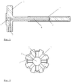
- Figure 1 is a schematic longitudinal-sectional view of an embodiment of a picker arm 1 for picking up and transporting hollow fiber membranes.
- Grooves 2 for holding the hollow fiber membranes are present on the circumference of the picker arm 1.
- Connecting bores 3 connect the grooves 2 to a central bore 4 extending along the center axis of the picker arm 1.
- the central bore 4 can be connected to a suction device, such as a vacuum pump, via a first port 5 or a second port 6. If only one of the ports is used, the other one has to be closed with a plug.
- Figure 2 is a schematic cross-sectional partial view of the picker arm 1 of Fig. 1 . Only the front part of the picker arm 1 is shown, not the base comprising the first port 5 and the second port 6.
- the central bore 4 is connected to the grooves 2 by connecting bores 3. Depressions 7 in the grooves 2 allow the vacuum to reach a larger portion of the surface of the fiber and increase the adhesion force.
- the picker arm 1 can hold eight hollow fiber membranes around its circumference. Typically, the number of fibers on the picker arm matches the number of fibers present in the final product to be produced using the hollow fiber membranes, i.e., a sterilizing filter. Thus, a sterilizing filter unit can be produced using the fibers held by one picker arm. There can be picker arms holding more or less than eight fibers, as also shown in the following figures.
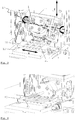
- Figure 3 is a schematic perspective view of an embodiment of the apparatus 10 of the present disclosure in a first position.
- the figure shows the arrangement of the picker arm 1 on the apparatus 10.
- the picker arm 1 is mounted on a moveable block 11 and can rotate around its longitudinal axis C, swing between a vertical and a horizontal position around axis A of the moveable block 11, and moved up and down along axis Z with the moveable block 11.
- the apparatus also comprises a slide 12 that holds a fiber cartridge 20.
- the slide 12 can move along axis X. A controlled combination of all these movements allows the picker arm 1 to pick up the fibers 21 from the cartridge 20 and attach them around its circumference.
- Figure 4 is a schematic perspective view of the apparatus 10 of Fig. 3 in a second position where the picker arm 1 is in a horizontal position above the first fiber 21 in the fiber cartridge 20. The vacuum fastening the fibers 21 in the fiber cartridge 20 is disabled and strong vacuum is applied to the picker arm 1.
- Figure 5 is a schematic perspective view of the apparatus 10 of Fig. 3 in a third position where the picker arm 1 is in a vertical position.
- the picker arm has already moved upwards (along axis Z) and inserted the fibers 21 into a disc 22 comprised of thermoplastic material.
- Widening pins 13 are in contact with the fibers 21.
- the heat is stored in a massive heater block 14.
- the complete arrangement of widening pins 13 can move up and down along axis Z1. If there is a separate welding unit (to increase the productivity), the widening pins 13 and the welding unit have to be movable along axis X1.
- Figure 6 shows a picker arm 1 of an embodiment of the apparatus 10 of the present disclosure in several stages of the process of the present disclosure.
- Picture a) shows the picker arm 1 without hollow fiber membranes 21.
- the picker arm 1 can feature several small bores 8 in the grooves 2 instead of a depression 7 as shown in Fig. 2 .
- the surface of the picker arm 1 has to be extremely smooth, to avoid any damage of the sensitive fibers 21.
- Picture b) shows the picker arm 1 with one attached fiber 21.
- Picture c) shows the picker arm 1 completely fit with fibers 21. In this case the picker arm 1 holds five fibers.
- Picture d) shows the picker arm 1 completely assembled with fibers 21 and a disc 22 comprised of thermoplastic material.
- the fibers 21 protrude from the disc 22 by several millimeters.
- a widening unit comprising widening pins 13 is in contact with the fibers 21.
- the vacuum of the picker arm 1 is working at full strength to prevent displacement of the fibers 21.
- Picture f) is a detail view of picture e) and shows the cone formed by the widening pins 13 on the part of the fibers 21 protruding from the disc 22.
- the size of the formed cone is important for the welding process. If the cone does not exist or is too small, the fiber 21 cannot be welded correctly into the disc 22, as the fiber 21 would slip into the bores of the disc 22. If the cone is too large, there a part of the fiber would remain above the disc 22 and protrude from it.
- the fiber 21 should be flush with the disc 22.
- Picture g) shows the step of welding the fibers 21 to the disc 22.
- the welding needs higher temperature than the widening. 22 It can be performed with the widening pins 13 or with separate welding pins, as the geometry and surface coating of both types of pins is identical.
- the welding can be performed in one step with a complete set of welding pins or it performed in several steps using a single welding pin or a subset of welding pins, depending of the mass and material of the fibers 21 and the disc 22.
- the fiber 21 is pressed downwards into the disc 22. Therefore, the vacuum of the picker arm 1 is reduced, so that the fiber 21 can slide along the picker arm 1 without being damaged.
- Picture h) shows a detail view of the filter element 30 after the welding step. The fibers 21 are tightly connected to the disc 22 and the fibers 21 are flush with the disc 22.
Landscapes
- Engineering & Computer Science (AREA)
- Mechanical Engineering (AREA)
- Manufacturing & Machinery (AREA)
- Chemical & Material Sciences (AREA)
- Chemical Kinetics & Catalysis (AREA)
- Textile Engineering (AREA)
- Separation Using Semi-Permeable Membranes (AREA)
Abstract
Description
- The present disclosure relates to an apparatus used in the production of a sterilizing filter for dead-end filtration of medical liquids which comprises a plurality of microporous hollow fiber membranes having a large inner diameter, and to a process for operating the apparatus.
- Liquids destined to be infused into a patient's body, in particular into the bloodstream of a patient, have to be free of pyrogens and particulate matter. To protect the patient, infusion solutions therefore typically are passed through a filter device installed in the infusion line before they enter the patient's body. Commercially available devices generally comprise a microporous flat sheet membrane. Filter devices comprising hollow fiber membranes instead of flat sheet membranes also have been proposed.
-
EP 3 405 277 A1EP 3 431 171 A1EP 3 388 141 A1 disclose semipermeable hollow fiber membranes having a large inner diameter and comparatively thin walls, as well as sterilizing filters for dead-end filtration of medical liquids comprising these semipermeable hollow fiber membranes. - Due to their large inner diameter and the comparatively thin wall, these hollow fiber membranes are easily damaged by mechanical stress and require particular care during processing.
- The present disclosure provides an apparatus and a process for producing a filter element of a sterilizing filter for medical liquids, e.g., water. The sterilizing filter is configured for dead-end filtration and comprises a plurality of microporous hollow fiber membranes having a large inner diameter.
-
- Figure 1
- is a schematic longitudinal-sectional view of an embodiment of a picker arm of the apparatus of the present disclosure;
- Figure 2
- is a cross-sectional partial view of the picker arm of
Fig. 1 ; - Figure 3
- is a schematic perspective view of an embodiment of the apparatus of the present disclosure in a first position;
- Figure 4
- is a schematic perspective view of the apparatus of
Fig. 3 in a second position; - Figure 5
- is a schematic perspective view of the apparatus of
Fig. 3 in a third position; - Figure 6
- shows a picker arm of an embodiment of the apparatus of the present disclosure in several stages of the process of the present disclosure.
- The present invention provides an apparatus and a process for producing a filter element of a sterilizing filter for medical liquids, e.g., water. The sterilizing filter is configured for dead-end filtration and comprises a plurality of microporous hollow fiber membranes having a large inner diameter. The liquid flows from the lumen of the hollow fiber membranes to the outside of the hollow fiber membranes and is filtered through the microporous wall of the hollow fiber membranes. Such a filter element can comprise a different number of fibers and the length of the hollow fiber membranes can be varied. This allows for tuning the effective membrane surface of the filter element to the requirements of the respective filtration process.
- The apparatus of the present invention is configured to transfer a number of hollow fiber membranes into bores of a disc comprised of a thermoplastic material and to weld the fibers to the wall of the bores using heat and pressure.
- In the filter element of the present disclosure, the hollow fiber membranes are heat-welded to the walls of bores in a disc comprised of a thermoplastic material. The disc separates the individual hollow fiber membranes from each other and also separates the compartment containing the unfiltered liquid from the compartment containing the filtered liquid in the finished sterilizing filter.
- Suitable thermoplastic materials for the disc are known in principle to the person skilled in the art and described in
EP 3 388 141 A1 - The number of fibers in the filter element can vary. In one embodiment, the filter element comprises at least two hollow fiber membranes, for instance, 2 to 12 hollow fiber membranes, or 4 to 10 hollow fiber membranes, or even 5 to 8 hollow fiber membranes. In an exemplary embodiment shown in the accompanying figures, the filter element comprises six fibers, and the disc of thermoplastic material which holds the fibers also is equipped with six bores.
- The microporous hollow fiber membranes having a large inner diameter and thin walls, such as the hollow fiber membranes taught in
EP 3 405 277 A1EP 3 431 171 A1 - In one embodiment, the microporous hollow fiber membranes have an inner diameter of from 2.8 to 4.0 mm, for instance, from 3.0 to 3.7 mm, or from 3.1 to 3.5 mm; and a wall thickness of from 100 to 500 µm, for instance, from 180 to 320 µm. The outer diameter of the microporous hollow fiber membranes is larger than 3 mm and smaller than 4.5 mm. In one embodiment, the ratio of inner diameter to wall thickness of the membranes is larger than 10, or even larger than 15.
- In one embodiment, the microporous hollow fiber membranes have a mean flow pore size, determined by capillary flow porometry, in the range of from 0.2 to 0.5 µm.
- Capillary flow porometry is a liquid extrusion technique in which the flow rates through wet and dry membranes at differential gas pressure are measured. Before measurement, the membrane is immersed in a low surface tension liquid (e.g., a perfluoroether commercially available under the trade name Porofil®) to ensure that all pores including the small ones are filled with the wetting liquid. By measuring the pressure at which the liquid is pressed out of the pores their corresponding diameter can be calculated using the Laplace equation. With this method, the pore size distribution of those pores that are active in the mass transport is determined. Dead-end and isolated pores are omitted. The hollow fiber membranes are measured inside-out.
- Laplace equation:

- Dp
- = diameter of pores [m]
- Υ
- = surface tension [N/m]; for Porofil® 0.016 [N/m]
- ΔP
- = pressure [Pa]
- Cos θ
- = contact angle; for complete wetting cos θ = 1
- In one embodiment, the microporous hollow fiber membranes comprise polyethersulfone (PESU) and polyvinylpyrrolidone (PVP). In one embodiment, the microporous hollow fiber membranes additionally comprise a polymer bearing cationic charges. Examples of suitable polymers bearing cationic charges include polyethyleneimines, modified polyethyleneimines, and modified polyphenyleneoxides.
- In one embodiment, the hollow fiber membranes are produced by a continuous solvent phase inversion spinning process comprising extruding a polymer solution through an outer ring slit of a nozzle with two concentric openings into a precipitation bath while simultaneously extruding a center fluid through the inner opening of the nozzle; subsequently washing the membrane obtained; cutting the membrane into sections having a predefined length, and subsequently drying the cut hollow fiber membranes.
- The apparatus of the present disclosure comprises a picker arm having a plurality of grooves configured to hold a hollow fiber membrane. The picker arm is configured to hold a plurality of hollow fiber membranes having an outer diameter which is larger than 3 mm and smaller than 4.5 mm.
- The number of grooves in the picker arm can vary. In one embodiment, the picker arm comprises at least two grooves, for instance, 2 to 12 grooves, or 4 to 10 hollow grooves, or even 5 to 8 grooves. In exemplary embodiments shown in the accompanying figures, the picker arm is equipped with eight or six grooves, respectively, for carrying hollow fiber membranes.
- The grooves of the picker arm are in fluid connection with a suction device, e.g., a vacuum pump. The reduced pressure attaches the hollow fiber membranes to the grooves of the picker arm. In one embodiment, elongated depressions which also are in fluid connection with the suction device are present in the grooves to increase the effect of the reduced pressure on the wall of the hollow fiber membrane, thereby increasing the force holding the hollow fiber membrane in position. In another embodiment, several small bores in fluid connection with the suction device are present in each groove.
- The picker arm is mounted on a movable block and can be rotated around its longitudinal axis, around a horizontal axis of the moveable block which is perpendicular to the longitudinal axis of the picker arm, and moved in vertical direction with the moveable block.
- The apparatus of the present disclosure also comprises a slide moveable in horizontal direction, i.e., parallel to the horizontal axis of the moveable block. The slide is configured to receive a fiber cartridge holding a plurality of hollow fiber membranes arranged in parallel and oriented in a direction perpendicular to the direction of movement of the slide. In one embodiment, bolts are present on the moveable slide which ensure a defined position of the fiber cartridge.
- A controlled combination of all these movements allows the picker arm to pick up the fibers from the fiber cartridge and to arrange them in the grooves on the picker arm.
- The apparatus of the present disclosure also comprises at least one heated metal pin having a conical shape, the maximum diameter of the heated metal pin being larger than the inner diameter of the hollow fiber membranes. In one embodiment, the at least one heated metal pin is covered with a non-stick coating. In one embodiment, the number of heated metal pins is equal to the number of fibers, i.e., the number of grooves on the picker arm. The at least one heated metal pin is moveable in a vertical direction and, optionally, in a horizontal direction.
- In one embodiment, the apparatus comprises two sets of heated metal pins having a conical shape, the maximum diameter of the heated metal pins being larger than the inner diameter of the hollow fiber membranes, each of the sets comprising at least one heated metal pin. In a further embodiment, each set comprises a number of heated metal pins equal to the number of fibers. The two sets are configured to be used alternatively. In one embodiment, one set of heated metal pins is configured to be used for widening the ends of the hollow fiber membranes, and the other set of heated metal pins is configured to be used for widening the ends of the hollow fiber membranes to the walls of the bores in the disc of thermoplastic material. Each of the two sets of heated metal pins is moveable in a vertical direction and in a horizontal direction. The pins can be positioned above the hollow fiber membranes by moving them in horizontal direction.
- The present invention also provides a process for manufacturing a filter element using the apparatus of the present disclosure.
- The process involves mounting a fiber cartridge comprising a plurality of hollow fiber membranes having an outer diameter which is larger than 3 mm and smaller than 4.5 mm on the moveable slide of the apparatus, attaching the hollow fiber membranes from the fiber cartridge to the grooves of the picker arm, threading the hollow fiber membranes through bores of a disc comprised of a thermoplastic material, introducing heated conical pins into the ends of the hollow fiber membranes protruding from the disc, widening the ends of the hollow fiber membranes and subsequently pushing down the ends of the hollow fiber membranes and welding them to the wall of the bores of the disc.
- In one embodiment of the process, the fibers are initially held in a closed fiber cartridge. The fiber cartridge is placed on the moveable slide of the apparatus of the present disclosure. In one embodiment, bolts are present on the moveable slide which ensure a defined position of the fiber cartridge.
- The upper part of the cartridge is removed. To keep the fibers in position despite the removal of the upper part of the cartridge, vacuum is applied to the fibers through bores in the bottom part of the cartridge.
- The hollow fiber membranes are removed from the cartridge by the picker arm one by one, and held in the grooves of the picker arm by applying vacuum. While the picker arm removes the fibers from the cartridge, the vacuum applied to the cartridge is disabled. The picker arm is rotatable around two axes and moveable in a vertical direction. The cartridge is also movable along a horizontal axis perpendicular to the longitudinal axis of the picker arm. A combination of these movements enables the picker arm to remove the fibers from the cartridge.
- Then the hollow fiber membranes are threaded into the bores of a disc. The picker arm is configured to hold all the hollow fiber membranes present in the cartridge, and to transfer them into the bores of the disc in a single step. Once the picker arm has collected all the hollow fiber membranes from the cartridge, it turns into a vertical position and moves upwards. The upper end of the hollow fiber membranes is guided into the bores of a disc comprised of a thermoplastic material and the hollow fiber membranes are pushed upward through the bores until they protrude from the upper side of the disc.
- An arrangement of heated metal pins moves downwards to widen the protruding ends of the hollow fiber membranes. In one embodiment, the number of metal pins is equal to the number of fibers. The pins have a conical shape, the diameter of the pins is slightly larger than the diameter of the hollow fiber membranes. The pins are covered with a non-stick coating. The temperature of the pins is lower than the melting temperature of the hollow fiber membranes. The hollow fiber membranes soften at the temperature of the pins and the upper end of the hollow fiber membranes is formed into a cone.
- In the next step, an arrangement of heated pins welds the hollow fiber membranes to the disc. The pins are identical to the pins of the previous step. The temperature of the welding pins is higher than in the previous step and sufficient to melt the thermoplastic material of the disc. During the welding process, the hollow fiber membrane is pressed into the bore of the disc, i.e., downwards. Therefore, the vacuum of the picker arm is reduced, so that the fiber can slide along the picker arm without being damaged.
- The same pins can be used for both, widening and welding. In one embodiment, there is a second set of welding pins to increase performance of the process. In another embodiment, only a single welding pin is used. A single pin transfers the heat directly to the welding area, while the rest of the disc and the hollow fiber membranes are unaffected. This effect can be used to prevent an undesired softening of the disc material in larger areas during the welding step which could lead to warping or deformation of the disk. This effect can be increased by a welding sequence wherein the hollow fiber membrane to be welded is as far away as possible from the previously welded hollow fiber membrane.
- Exemplary embodiments of the apparatus and the process of the present disclosure are shown in the accompanying figures and are described below. It will be understood that the features mentioned above and those described hereinafter can be used not only in the combination specified but also in other combinations or on their own, without departing from the scope of the present invention.
-
Figure 1 is a schematic longitudinal-sectional view of an embodiment of apicker arm 1 for picking up and transporting hollow fiber membranes.Grooves 2 for holding the hollow fiber membranes are present on the circumference of thepicker arm 1. Connectingbores 3 connect thegrooves 2 to acentral bore 4 extending along the center axis of thepicker arm 1. Thecentral bore 4 can be connected to a suction device, such as a vacuum pump, via afirst port 5 or a second port 6. If only one of the ports is used, the other one has to be closed with a plug. -
Figure 2 is a schematic cross-sectional partial view of thepicker arm 1 ofFig. 1 . Only the front part of thepicker arm 1 is shown, not the base comprising thefirst port 5 and the second port 6. Thecentral bore 4 is connected to thegrooves 2 by connectingbores 3.Depressions 7 in thegrooves 2 allow the vacuum to reach a larger portion of the surface of the fiber and increase the adhesion force. - The
picker arm 1 can hold eight hollow fiber membranes around its circumference. Typically, the number of fibers on the picker arm matches the number of fibers present in the final product to be produced using the hollow fiber membranes, i.e., a sterilizing filter. Thus, a sterilizing filter unit can be produced using the fibers held by one picker arm. There can be picker arms holding more or less than eight fibers, as also shown in the following figures. -
Figure 3 is a schematic perspective view of an embodiment of theapparatus 10 of the present disclosure in a first position. The figure shows the arrangement of thepicker arm 1 on theapparatus 10. Thepicker arm 1 is mounted on amoveable block 11 and can rotate around its longitudinal axis C, swing between a vertical and a horizontal position around axis A of themoveable block 11, and moved up and down along axis Z with themoveable block 11. The apparatus also comprises aslide 12 that holds afiber cartridge 20. Theslide 12 can move along axis X. A controlled combination of all these movements allows thepicker arm 1 to pick up thefibers 21 from thecartridge 20 and attach them around its circumference. -
Figure 4 is a schematic perspective view of theapparatus 10 ofFig. 3 in a second position where thepicker arm 1 is in a horizontal position above thefirst fiber 21 in thefiber cartridge 20. The vacuum fastening thefibers 21 in thefiber cartridge 20 is disabled and strong vacuum is applied to thepicker arm 1. -
Figure 5 is a schematic perspective view of theapparatus 10 ofFig. 3 in a third position where thepicker arm 1 is in a vertical position. The picker arm has already moved upwards (along axis Z) and inserted thefibers 21 into adisc 22 comprised of thermoplastic material. Widening pins 13 are in contact with thefibers 21. The heat is stored in amassive heater block 14. The complete arrangement of wideningpins 13 can move up and down along axis Z1. If there is a separate welding unit (to increase the productivity), the wideningpins 13 and the welding unit have to be movable along axis X1. -
Figure 6 shows apicker arm 1 of an embodiment of theapparatus 10 of the present disclosure in several stages of the process of the present disclosure. Picture a) shows thepicker arm 1 withouthollow fiber membranes 21. Thepicker arm 1 can feature severalsmall bores 8 in thegrooves 2 instead of adepression 7 as shown inFig. 2 . The surface of thepicker arm 1 has to be extremely smooth, to avoid any damage of thesensitive fibers 21. Picture b) shows thepicker arm 1 with one attachedfiber 21. Picture c) shows thepicker arm 1 completely fit withfibers 21. In this case thepicker arm 1 holds five fibers. Picture d) shows thepicker arm 1 completely assembled withfibers 21 and adisc 22 comprised of thermoplastic material. Thefibers 21 protrude from thedisc 22 by several millimeters. In picture e), a widening unit comprising wideningpins 13 is in contact with thefibers 21. The vacuum of thepicker arm 1 is working at full strength to prevent displacement of thefibers 21. Picture f) is a detail view of picture e) and shows the cone formed by the widening pins 13 on the part of thefibers 21 protruding from thedisc 22. The size of the formed cone is important for the welding process. If the cone does not exist or is too small, thefiber 21 cannot be welded correctly into thedisc 22, as thefiber 21 would slip into the bores of thedisc 22. If the cone is too large, there a part of the fiber would remain above thedisc 22 and protrude from it. After the heat sealing process, thefiber 21 should be flush with thedisc 22. Picture g) shows the step of welding thefibers 21 to thedisc 22. The welding needs higher temperature than the widening. 22 It can be performed with the wideningpins 13 or with separate welding pins, as the geometry and surface coating of both types of pins is identical. The welding can be performed in one step with a complete set of welding pins or it performed in several steps using a single welding pin or a subset of welding pins, depending of the mass and material of thefibers 21 and thedisc 22. During the welding process, thefiber 21 is pressed downwards into thedisc 22. Therefore, the vacuum of thepicker arm 1 is reduced, so that thefiber 21 can slide along thepicker arm 1 without being damaged. Picture h) shows a detail view of thefilter element 30 after the welding step. Thefibers 21 are tightly connected to thedisc 22 and thefibers 21 are flush with thedisc 22. -
- 1
- picker arm
- 2
- groove
- 3
- connecting bore
- 4
- central bore
- 5
- first vacuum port
- 6
- second vacuum port
- 7
- depression
- 8
- small bore
- 10
- apparatus
- 11
- moveable block
- 12
- slide
- 13
- widening pins / welding pins
- 14
- heater block
- 20
- fiber cartridge
- 21
- hollow fiber membrane
- 22
- disc comprised of thermoplastic material
- 30
- filter element
Claims (15)
- An apparatus (10) for producing a filter element (30), comprisinga picker arm (1) having a plurality of grooves (2), each groove (2) being configured to hold a hollow fiber membrane having an outer diameter which is larger than 3 mm and smaller than 4.5 mm, and being in fluid connection with a suction device;the picker arm (1) being mounted on a moveable block (11) and being rotatable around its longitudinal axis (C), around a horizontal axis (A) of the moveable block (11) which is perpendicular to the longitudinal axis (C) of the picker arm (1), and moved in a vertical direction (Z) with the moveable block (11);a slide (12) moveable in a horizontal direction (X) and being configured to receive a fiber cartridge (20) holding a plurality of hollow fiber membranes (21) arranged in parallel and oriented in a direction perpendicular to the horizontal direction (X);at least one heated metal pin (13) having a conical shape, the maximum diameter of the heated metal pin (13) being larger than the inner diameter of the hollow fiber membranes (21), the least one heated metal pin (13) moveable in a vertical direction (Z1) and, optionally, in a horizontal direction (X1).
- The apparatus (10) of claim 1, wherein the number of grooves (2) on the picker arm (1) is in the range of from 5 to 8.
- The apparatus (10) of claim 1 or 2, wherein each groove (2) of the picker arm (1) features an elongated depression (7).
- The apparatus (10) of claims 1 or 2, wherein each groove (2) of the picker arm (1) features a plurality of small bores (8) in fluid connection with the suction device.
- The apparatus (10) of any one of claims 1 to 4, wherein the number of hollow fiber membranes (21) held in the fiber cartridge (20) is in the range of from 5 to 8.
- The apparatus (10) of any one of claims 1 to 5, wherein bolts are present on the moveable slide (12) which are configures to interact with the fiber cartridge (20) and ensure a defined position of the fiber cartridge (20) on the moveable slide (12).
- The apparatus (10) of any one of claims 1 to 6, wherein the at least one heated metal pin (13) is covered with a non-stick coating.
- The apparatus (10) of any one of claims 1 to 7, wherein the number of heated metal pins (13) is equal to the number of grooves (2) on the picker arm (1).
- The apparatus (10) of any one of claims 1 to 8, comprising two sets of heated metal pins (13) having a conical shape, the maximum diameter of the heated metal pins (13) being larger than the inner diameter of the hollow fiber membranes (21), each of the sets comprising at least one heated metal pin (13).
- The apparatus (10) of claims 9, wherein each of the two sets of heated metal pins (13) is moveable in a vertical direction (Z1) and in a horizontal direction (X1).
- A process for the production of a filter element (30), comprising mounting a fiber cartridge (20) comprising a plurality of hollow fiber membranes (21) having an outer diameter which is larger than 3 mm and smaller than 4.5 mm on the moveable slide (12) of the apparatus (10) of any one of claims 1 to 10, attaching the hollow fiber membranes (21) from the fiber cartridge (20) to the grooves (2) of the picker arm (1) of the apparatus (10) of any one of claims 1 to 10, threading the hollow fiber membranes (21) through bores of a disc (22) comprised of a thermoplastic material, introducing heated metal pins (13) of the apparatus (10) of any one of claims 1 to 10 into the ends of the hollow fiber membranes (21) protruding from the disc (22), widening the ends of the hollow fiber membranes (21) and subsequently pushing the ends of the hollow fiber membranes (21) into the bores of the disc (22) and welding them to the wall of the bores of the disc (22).
- The process of claim 11, wherein different heated metal pins (13) are used for widening the ends of the hollow fiber membranes (21) and for pushing the ends of the hollow fiber membranes (21) into the bores of the disc (22) and welding them to the wall of the bores of the disc (22) .
- The process of claim 11, wherein a single heated metal pin (13) is used in sequence for widening the end of every hollow fiber membrane (21) and for pushing the end of the hollow fiber membrane (21) into the corresponding bore of the disc (22) and welding it to the wall of the bore of the disc (22).
- The process of any one of claims 11 to 13, wherein the hollow fiber membranes (21) comprise at least one polyethersulfone (PESU) and at least one polyvinylpyrrolidone (PVP).
- The process of any one of claims 11 to 14, wherein the hollow fiber membranes (21) additionally comprise a polymer bearing cationic charges.
Priority Applications (3)
| Application Number | Priority Date | Filing Date | Title |
|---|---|---|---|
| EP19220173.9A EP3845300B1 (en) | 2019-12-31 | 2019-12-31 | Apparatus and process for producing a filter element |
| US17/788,066 US12042767B2 (en) | 2019-12-31 | 2020-12-29 | Apparatus and process for producing a filter element |
| PCT/EP2020/087959 WO2021136768A1 (en) | 2019-12-31 | 2020-12-29 | Apparatus and process for producing a filter element |
Applications Claiming Priority (1)
| Application Number | Priority Date | Filing Date | Title |
|---|---|---|---|
| EP19220173.9A EP3845300B1 (en) | 2019-12-31 | 2019-12-31 | Apparatus and process for producing a filter element |
Publications (2)
| Publication Number | Publication Date |
|---|---|
| EP3845300A1 true EP3845300A1 (en) | 2021-07-07 |
| EP3845300B1 EP3845300B1 (en) | 2024-09-11 |
Family
ID=69061184
Family Applications (1)
| Application Number | Title | Priority Date | Filing Date |
|---|---|---|---|
| EP19220173.9A Active EP3845300B1 (en) | 2019-12-31 | 2019-12-31 | Apparatus and process for producing a filter element |
Country Status (3)
| Country | Link |
|---|---|
| US (1) | US12042767B2 (en) |
| EP (1) | EP3845300B1 (en) |
| WO (1) | WO2021136768A1 (en) |
Citations (6)
| Publication number | Priority date | Publication date | Assignee | Title |
|---|---|---|---|---|
| JPS6039304U (en) * | 1983-08-23 | 1985-03-19 | 東レ株式会社 | Separation hollow fiber bundle moving device |
| EP3388141A1 (en) | 2017-04-12 | 2018-10-17 | Gambro Lundia AB | Filtration device |
| EP3405277A1 (en) | 2016-01-22 | 2018-11-28 | Gambro Lundia AB | Filter membrane and device |
| CN108993160A (en) * | 2018-08-10 | 2018-12-14 | 东莞理工学院 | A kind of gyropilot of hollow fiber film thread |
| EP3431171A1 (en) | 2017-07-19 | 2019-01-23 | Gambro Lundia AB | Filter membrane and device |
| WO2019018200A1 (en) * | 2017-07-17 | 2019-01-24 | Baxter International Inc. | Medical product including pre-filled product bag |
Family Cites Families (1)
| Publication number | Priority date | Publication date | Assignee | Title |
|---|---|---|---|---|
| JPH0339304A (en) | 1989-07-05 | 1991-02-20 | Hakusui Chem Ind Ltd | Adamantyl monocrotonate-based polymer |
-
2019
- 2019-12-31 EP EP19220173.9A patent/EP3845300B1/en active Active
-
2020
- 2020-12-29 US US17/788,066 patent/US12042767B2/en active Active
- 2020-12-29 WO PCT/EP2020/087959 patent/WO2021136768A1/en not_active Ceased
Patent Citations (7)
| Publication number | Priority date | Publication date | Assignee | Title |
|---|---|---|---|---|
| JPS6039304U (en) * | 1983-08-23 | 1985-03-19 | 東レ株式会社 | Separation hollow fiber bundle moving device |
| EP3405277A1 (en) | 2016-01-22 | 2018-11-28 | Gambro Lundia AB | Filter membrane and device |
| EP3388141A1 (en) | 2017-04-12 | 2018-10-17 | Gambro Lundia AB | Filtration device |
| WO2019018200A1 (en) * | 2017-07-17 | 2019-01-24 | Baxter International Inc. | Medical product including pre-filled product bag |
| EP3431171A1 (en) | 2017-07-19 | 2019-01-23 | Gambro Lundia AB | Filter membrane and device |
| CN108993160A (en) * | 2018-08-10 | 2018-12-14 | 东莞理工学院 | A kind of gyropilot of hollow fiber film thread |
| US20200047127A1 (en) * | 2018-08-10 | 2020-02-13 | Dongguan University Of Technology | Automatic operating device for hollow fiber membrane |
Also Published As
| Publication number | Publication date |
|---|---|
| US20230039445A1 (en) | 2023-02-09 |
| WO2021136768A1 (en) | 2021-07-08 |
| US12042767B2 (en) | 2024-07-23 |
| EP3845300B1 (en) | 2024-09-11 |
Similar Documents
| Publication | Publication Date | Title |
|---|---|---|
| EP3405277B1 (en) | Process for preparing a filter membrane | |
| CN104159654B (en) | Hollow fiber cassettes and components and methods of their construction | |
| US9295947B2 (en) | Centrifugal filter | |
| US9149770B2 (en) | Hollow fiber capillary membrane and method for the production thereof | |
| JP4678776B2 (en) | Hollow fiber membrane fluid processor | |
| US20090229466A1 (en) | Blood treatment dialyzer/filter for permitting gas removal | |
| JP7232179B2 (en) | Method for determining permeation properties of hollow fiber membrane bundles | |
| KR20010109287A (en) | Perfluorinated thermoplastic filter cartridge | |
| EP4084896A1 (en) | Device for cutting hollow fiber membranes | |
| WO2007036332A2 (en) | Single-piece filter element and a method for the production thereof | |
| EP3845300B1 (en) | Apparatus and process for producing a filter element | |
| EP3845299B1 (en) | Hollow fiber membrane transport cartridge | |
| EP4084895B1 (en) | Process for manufacturing a sterilizing filter | |
| US20090236027A1 (en) | Blood Treatment Filter and Method of Manufacturing | |
| US20090218272A1 (en) | micro fluidic system and a method of attaching a membrane to a tube | |
| US20250050276A1 (en) | Process for making a filtration and/or diffusion device | |
| EP3842129A1 (en) | Sterile filter assembly | |
| CA2390214C (en) | Dialyzer | |
| KR101530666B1 (en) | Micro filter and manufacture method thereof |
Legal Events
| Date | Code | Title | Description |
|---|---|---|---|
| PUAI | Public reference made under article 153(3) epc to a published international application that has entered the european phase |
Free format text: ORIGINAL CODE: 0009012 |
|
| STAA | Information on the status of an ep patent application or granted ep patent |
Free format text: STATUS: THE APPLICATION HAS BEEN PUBLISHED |
|
| AK | Designated contracting states |
Kind code of ref document: A1 Designated state(s): AL AT BE BG CH CY CZ DE DK EE ES FI FR GB GR HR HU IE IS IT LI LT LU LV MC MK MT NL NO PL PT RO RS SE SI SK SM TR |
|
| STAA | Information on the status of an ep patent application or granted ep patent |
Free format text: STATUS: REQUEST FOR EXAMINATION WAS MADE |
|
| 17P | Request for examination filed |
Effective date: 20211220 |
|
| RBV | Designated contracting states (corrected) |
Designated state(s): AL AT BE BG CH CY CZ DE DK EE ES FI FR GB GR HR HU IE IS IT LI LT LU LV MC MK MT NL NO PL PT RO RS SE SI SK SM TR |
|
| RIC1 | Information provided on ipc code assigned before grant |
Ipc: B29L 31/14 20060101ALI20240415BHEP Ipc: B29C 65/78 20060101ALI20240415BHEP Ipc: B29C 65/00 20060101ALI20240415BHEP Ipc: B29C 65/18 20060101ALI20240415BHEP Ipc: B29C 65/24 20060101ALI20240415BHEP Ipc: B01D 63/02 20060101AFI20240415BHEP |
|
| GRAP | Despatch of communication of intention to grant a patent |
Free format text: ORIGINAL CODE: EPIDOSNIGR1 |
|
| STAA | Information on the status of an ep patent application or granted ep patent |
Free format text: STATUS: GRANT OF PATENT IS INTENDED |
|
| GRAS | Grant fee paid |
Free format text: ORIGINAL CODE: EPIDOSNIGR3 |
|
| GRAA | (expected) grant |
Free format text: ORIGINAL CODE: 0009210 |
|
| STAA | Information on the status of an ep patent application or granted ep patent |
Free format text: STATUS: THE PATENT HAS BEEN GRANTED |
|
| INTG | Intention to grant announced |
Effective date: 20240801 |
|
| AK | Designated contracting states |
Kind code of ref document: B1 Designated state(s): AL AT BE BG CH CY CZ DE DK EE ES FI FR GB GR HR HU IE IS IT LI LT LU LV MC MK MT NL NO PL PT RO RS SE SI SK SM TR |
|
| REG | Reference to a national code |
Ref country code: GB Ref legal event code: FG4D |
|
| REG | Reference to a national code |
Ref country code: CH Ref legal event code: EP |
|
| REG | Reference to a national code |
Ref country code: DE Ref legal event code: R096 Ref document number: 602019058641 Country of ref document: DE |
|
| REG | Reference to a national code |
Ref country code: IE Ref legal event code: FG4D |
|
| REG | Reference to a national code |
Ref country code: LT Ref legal event code: MG9D |
|
| PG25 | Lapsed in a contracting state [announced via postgrant information from national office to epo] |
Ref country code: NO Free format text: LAPSE BECAUSE OF FAILURE TO SUBMIT A TRANSLATION OF THE DESCRIPTION OR TO PAY THE FEE WITHIN THE PRESCRIBED TIME-LIMIT Effective date: 20241211 |
|
| REG | Reference to a national code |
Ref country code: NL Ref legal event code: MP Effective date: 20240911 |
|
| PG25 | Lapsed in a contracting state [announced via postgrant information from national office to epo] |
Ref country code: FI Free format text: LAPSE BECAUSE OF FAILURE TO SUBMIT A TRANSLATION OF THE DESCRIPTION OR TO PAY THE FEE WITHIN THE PRESCRIBED TIME-LIMIT Effective date: 20240911 Ref country code: GR Free format text: LAPSE BECAUSE OF FAILURE TO SUBMIT A TRANSLATION OF THE DESCRIPTION OR TO PAY THE FEE WITHIN THE PRESCRIBED TIME-LIMIT Effective date: 20241212 |
|
| PG25 | Lapsed in a contracting state [announced via postgrant information from national office to epo] |
Ref country code: BG Free format text: LAPSE BECAUSE OF FAILURE TO SUBMIT A TRANSLATION OF THE DESCRIPTION OR TO PAY THE FEE WITHIN THE PRESCRIBED TIME-LIMIT Effective date: 20240911 |
|
| PG25 | Lapsed in a contracting state [announced via postgrant information from national office to epo] |
Ref country code: LV Free format text: LAPSE BECAUSE OF FAILURE TO SUBMIT A TRANSLATION OF THE DESCRIPTION OR TO PAY THE FEE WITHIN THE PRESCRIBED TIME-LIMIT Effective date: 20240911 |
|
| PG25 | Lapsed in a contracting state [announced via postgrant information from national office to epo] |
Ref country code: HR Free format text: LAPSE BECAUSE OF FAILURE TO SUBMIT A TRANSLATION OF THE DESCRIPTION OR TO PAY THE FEE WITHIN THE PRESCRIBED TIME-LIMIT Effective date: 20240911 |
|
| PG25 | Lapsed in a contracting state [announced via postgrant information from national office to epo] |
Ref country code: ES Free format text: LAPSE BECAUSE OF FAILURE TO SUBMIT A TRANSLATION OF THE DESCRIPTION OR TO PAY THE FEE WITHIN THE PRESCRIBED TIME-LIMIT Effective date: 20240911 |
|
| PG25 | Lapsed in a contracting state [announced via postgrant information from national office to epo] |
Ref country code: NO Free format text: LAPSE BECAUSE OF FAILURE TO SUBMIT A TRANSLATION OF THE DESCRIPTION OR TO PAY THE FEE WITHIN THE PRESCRIBED TIME-LIMIT Effective date: 20241211 Ref country code: LV Free format text: LAPSE BECAUSE OF FAILURE TO SUBMIT A TRANSLATION OF THE DESCRIPTION OR TO PAY THE FEE WITHIN THE PRESCRIBED TIME-LIMIT Effective date: 20240911 Ref country code: HR Free format text: LAPSE BECAUSE OF FAILURE TO SUBMIT A TRANSLATION OF THE DESCRIPTION OR TO PAY THE FEE WITHIN THE PRESCRIBED TIME-LIMIT Effective date: 20240911 Ref country code: GR Free format text: LAPSE BECAUSE OF FAILURE TO SUBMIT A TRANSLATION OF THE DESCRIPTION OR TO PAY THE FEE WITHIN THE PRESCRIBED TIME-LIMIT Effective date: 20241212 Ref country code: FI Free format text: LAPSE BECAUSE OF FAILURE TO SUBMIT A TRANSLATION OF THE DESCRIPTION OR TO PAY THE FEE WITHIN THE PRESCRIBED TIME-LIMIT Effective date: 20240911 Ref country code: ES Free format text: LAPSE BECAUSE OF FAILURE TO SUBMIT A TRANSLATION OF THE DESCRIPTION OR TO PAY THE FEE WITHIN THE PRESCRIBED TIME-LIMIT Effective date: 20240911 Ref country code: BG Free format text: LAPSE BECAUSE OF FAILURE TO SUBMIT A TRANSLATION OF THE DESCRIPTION OR TO PAY THE FEE WITHIN THE PRESCRIBED TIME-LIMIT Effective date: 20240911 |
|
| REG | Reference to a national code |
Ref country code: AT Ref legal event code: MK05 Ref document number: 1722207 Country of ref document: AT Kind code of ref document: T Effective date: 20240911 |
|
| PG25 | Lapsed in a contracting state [announced via postgrant information from national office to epo] |
Ref country code: NL Free format text: LAPSE BECAUSE OF FAILURE TO SUBMIT A TRANSLATION OF THE DESCRIPTION OR TO PAY THE FEE WITHIN THE PRESCRIBED TIME-LIMIT Effective date: 20240911 |
|
| PG25 | Lapsed in a contracting state [announced via postgrant information from national office to epo] |
Ref country code: IS Free format text: LAPSE BECAUSE OF FAILURE TO SUBMIT A TRANSLATION OF THE DESCRIPTION OR TO PAY THE FEE WITHIN THE PRESCRIBED TIME-LIMIT Effective date: 20250111 Ref country code: PT Free format text: LAPSE BECAUSE OF FAILURE TO SUBMIT A TRANSLATION OF THE DESCRIPTION OR TO PAY THE FEE WITHIN THE PRESCRIBED TIME-LIMIT Effective date: 20250113 |
|
| PG25 | Lapsed in a contracting state [announced via postgrant information from national office to epo] |
Ref country code: RO Free format text: LAPSE BECAUSE OF FAILURE TO SUBMIT A TRANSLATION OF THE DESCRIPTION OR TO PAY THE FEE WITHIN THE PRESCRIBED TIME-LIMIT Effective date: 20240911 Ref country code: SM Free format text: LAPSE BECAUSE OF FAILURE TO SUBMIT A TRANSLATION OF THE DESCRIPTION OR TO PAY THE FEE WITHIN THE PRESCRIBED TIME-LIMIT Effective date: 20240911 |
|
| PG25 | Lapsed in a contracting state [announced via postgrant information from national office to epo] |
Ref country code: EE Free format text: LAPSE BECAUSE OF FAILURE TO SUBMIT A TRANSLATION OF THE DESCRIPTION OR TO PAY THE FEE WITHIN THE PRESCRIBED TIME-LIMIT Effective date: 20240911 Ref country code: AT Free format text: LAPSE BECAUSE OF FAILURE TO SUBMIT A TRANSLATION OF THE DESCRIPTION OR TO PAY THE FEE WITHIN THE PRESCRIBED TIME-LIMIT Effective date: 20240911 |
|
| PG25 | Lapsed in a contracting state [announced via postgrant information from national office to epo] |
Ref country code: PL Free format text: LAPSE BECAUSE OF FAILURE TO SUBMIT A TRANSLATION OF THE DESCRIPTION OR TO PAY THE FEE WITHIN THE PRESCRIBED TIME-LIMIT Effective date: 20240911 Ref country code: CZ Free format text: LAPSE BECAUSE OF FAILURE TO SUBMIT A TRANSLATION OF THE DESCRIPTION OR TO PAY THE FEE WITHIN THE PRESCRIBED TIME-LIMIT Effective date: 20240911 |
|
| PG25 | Lapsed in a contracting state [announced via postgrant information from national office to epo] |
Ref country code: SK Free format text: LAPSE BECAUSE OF FAILURE TO SUBMIT A TRANSLATION OF THE DESCRIPTION OR TO PAY THE FEE WITHIN THE PRESCRIBED TIME-LIMIT Effective date: 20240911 Ref country code: IT Free format text: LAPSE BECAUSE OF FAILURE TO SUBMIT A TRANSLATION OF THE DESCRIPTION OR TO PAY THE FEE WITHIN THE PRESCRIBED TIME-LIMIT Effective date: 20240911 |
|
| PG25 | Lapsed in a contracting state [announced via postgrant information from national office to epo] |
Ref country code: RS Free format text: LAPSE BECAUSE OF FAILURE TO SUBMIT A TRANSLATION OF THE DESCRIPTION OR TO PAY THE FEE WITHIN THE PRESCRIBED TIME-LIMIT Effective date: 20240911 |
|
| REG | Reference to a national code |
Ref country code: DE Ref legal event code: R097 Ref document number: 602019058641 Country of ref document: DE |
|
| PG25 | Lapsed in a contracting state [announced via postgrant information from national office to epo] |
Ref country code: MC Free format text: LAPSE BECAUSE OF FAILURE TO SUBMIT A TRANSLATION OF THE DESCRIPTION OR TO PAY THE FEE WITHIN THE PRESCRIBED TIME-LIMIT Effective date: 20240911 |
|
| PG25 | Lapsed in a contracting state [announced via postgrant information from national office to epo] |
Ref country code: DK Free format text: LAPSE BECAUSE OF FAILURE TO SUBMIT A TRANSLATION OF THE DESCRIPTION OR TO PAY THE FEE WITHIN THE PRESCRIBED TIME-LIMIT Effective date: 20240911 |
|
| PLBE | No opposition filed within time limit |
Free format text: ORIGINAL CODE: 0009261 |
|
| STAA | Information on the status of an ep patent application or granted ep patent |
Free format text: STATUS: NO OPPOSITION FILED WITHIN TIME LIMIT |
|
| REG | Reference to a national code |
Ref country code: CH Ref legal event code: PL |
|
| PG25 | Lapsed in a contracting state [announced via postgrant information from national office to epo] |
Ref country code: LU Free format text: LAPSE BECAUSE OF NON-PAYMENT OF DUE FEES Effective date: 20241231 |
|
| 26N | No opposition filed |
Effective date: 20250612 |
|
| PG25 | Lapsed in a contracting state [announced via postgrant information from national office to epo] |
Ref country code: SE Free format text: LAPSE BECAUSE OF FAILURE TO SUBMIT A TRANSLATION OF THE DESCRIPTION OR TO PAY THE FEE WITHIN THE PRESCRIBED TIME-LIMIT Effective date: 20240911 |
|
| REG | Reference to a national code |
Ref country code: BE Ref legal event code: MM Effective date: 20241231 |
|
| PG25 | Lapsed in a contracting state [announced via postgrant information from national office to epo] |
Ref country code: BE Free format text: LAPSE BECAUSE OF NON-PAYMENT OF DUE FEES Effective date: 20241231 |
|
| PG25 | Lapsed in a contracting state [announced via postgrant information from national office to epo] |
Ref country code: CH Free format text: LAPSE BECAUSE OF NON-PAYMENT OF DUE FEES Effective date: 20241231 |
|
| PG25 | Lapsed in a contracting state [announced via postgrant information from national office to epo] |
Ref country code: IE Free format text: LAPSE BECAUSE OF NON-PAYMENT OF DUE FEES Effective date: 20241231 |
|
| PGFP | Annual fee paid to national office [announced via postgrant information from national office to epo] |
Ref country code: DE Payment date: 20251126 Year of fee payment: 7 |
|
| PGFP | Annual fee paid to national office [announced via postgrant information from national office to epo] |
Ref country code: GB Payment date: 20251119 Year of fee payment: 7 |
|
| PGFP | Annual fee paid to national office [announced via postgrant information from national office to epo] |
Ref country code: FR Payment date: 20251120 Year of fee payment: 7 |
|
| PG25 | Lapsed in a contracting state [announced via postgrant information from national office to epo] |
Ref country code: CY Free format text: LAPSE BECAUSE OF FAILURE TO SUBMIT A TRANSLATION OF THE DESCRIPTION OR TO PAY THE FEE WITHIN THE PRESCRIBED TIME-LIMIT Effective date: 20240911 |
|
| PG25 | Lapsed in a contracting state [announced via postgrant information from national office to epo] |
Ref country code: TR Free format text: LAPSE BECAUSE OF FAILURE TO SUBMIT A TRANSLATION OF THE DESCRIPTION OR TO PAY THE FEE WITHIN THE PRESCRIBED TIME-LIMIT Effective date: 20240911 |
|
| PG25 | Lapsed in a contracting state [announced via postgrant information from national office to epo] |
Ref country code: HU Free format text: LAPSE BECAUSE OF FAILURE TO SUBMIT A TRANSLATION OF THE DESCRIPTION OR TO PAY THE FEE WITHIN THE PRESCRIBED TIME-LIMIT; INVALID AB INITIO Effective date: 20191231 |
|
| PG25 | Lapsed in a contracting state [announced via postgrant information from national office to epo] |
Ref country code: SI Free format text: LAPSE BECAUSE OF FAILURE TO SUBMIT A TRANSLATION OF THE DESCRIPTION OR TO PAY THE FEE WITHIN THE PRESCRIBED TIME-LIMIT Effective date: 20240911 |
|
| PG25 | Lapsed in a contracting state [announced via postgrant information from national office to epo] |
Ref country code: LT Free format text: LAPSE BECAUSE OF FAILURE TO SUBMIT A TRANSLATION OF THE DESCRIPTION OR TO PAY THE FEE WITHIN THE PRESCRIBED TIME-LIMIT Effective date: 20240911 |