EP3845137A1 - Retractable tether in apical pad - Google Patents
Retractable tether in apical pad Download PDFInfo
- Publication number
- EP3845137A1 EP3845137A1 EP20216127.9A EP20216127A EP3845137A1 EP 3845137 A1 EP3845137 A1 EP 3845137A1 EP 20216127 A EP20216127 A EP 20216127A EP 3845137 A1 EP3845137 A1 EP 3845137A1
- Authority
- EP
- European Patent Office
- Prior art keywords
- tether
- capture device
- rim
- hub
- void
- Prior art date
- Legal status (The legal status is an assumption and is not a legal conclusion. Google has not performed a legal analysis and makes no representation as to the accuracy of the status listed.)
- Pending
Links
Images


Classifications
-
- A—HUMAN NECESSITIES
- A61—MEDICAL OR VETERINARY SCIENCE; HYGIENE
- A61B—DIAGNOSIS; SURGERY; IDENTIFICATION
- A61B17/00—Surgical instruments, devices or methods, e.g. tourniquets
- A61B17/04—Surgical instruments, devices or methods, e.g. tourniquets for suturing wounds; Holders or packages for needles or suture materials
- A61B17/0401—Suture anchors, buttons or pledgets, i.e. means for attaching sutures to bone, cartilage or soft tissue; Instruments for applying or removing suture anchors
-
- A—HUMAN NECESSITIES
- A61—MEDICAL OR VETERINARY SCIENCE; HYGIENE
- A61F—FILTERS IMPLANTABLE INTO BLOOD VESSELS; PROSTHESES; DEVICES PROVIDING PATENCY TO, OR PREVENTING COLLAPSING OF, TUBULAR STRUCTURES OF THE BODY, e.g. STENTS; ORTHOPAEDIC, NURSING OR CONTRACEPTIVE DEVICES; FOMENTATION; TREATMENT OR PROTECTION OF EYES OR EARS; BANDAGES, DRESSINGS OR ABSORBENT PADS; FIRST-AID KITS
- A61F2/00—Filters implantable into blood vessels; Prostheses, i.e. artificial substitutes or replacements for parts of the body; Appliances for connecting them with the body; Devices providing patency to, or preventing collapsing of, tubular structures of the body, e.g. stents
- A61F2/02—Prostheses implantable into the body
- A61F2/24—Heart valves ; Vascular valves, e.g. venous valves; Heart implants, e.g. passive devices for improving the function of the native valve or the heart muscle; Transmyocardial revascularisation [TMR] devices; Valves implantable in the body
- A61F2/2412—Heart valves ; Vascular valves, e.g. venous valves; Heart implants, e.g. passive devices for improving the function of the native valve or the heart muscle; Transmyocardial revascularisation [TMR] devices; Valves implantable in the body with soft flexible valve members, e.g. tissue valves shaped like natural valves
- A61F2/2418—Scaffolds therefor, e.g. support stents
-
- A—HUMAN NECESSITIES
- A61—MEDICAL OR VETERINARY SCIENCE; HYGIENE
- A61F—FILTERS IMPLANTABLE INTO BLOOD VESSELS; PROSTHESES; DEVICES PROVIDING PATENCY TO, OR PREVENTING COLLAPSING OF, TUBULAR STRUCTURES OF THE BODY, e.g. STENTS; ORTHOPAEDIC, NURSING OR CONTRACEPTIVE DEVICES; FOMENTATION; TREATMENT OR PROTECTION OF EYES OR EARS; BANDAGES, DRESSINGS OR ABSORBENT PADS; FIRST-AID KITS
- A61F2/00—Filters implantable into blood vessels; Prostheses, i.e. artificial substitutes or replacements for parts of the body; Appliances for connecting them with the body; Devices providing patency to, or preventing collapsing of, tubular structures of the body, e.g. stents
- A61F2/02—Prostheses implantable into the body
- A61F2/24—Heart valves ; Vascular valves, e.g. venous valves; Heart implants, e.g. passive devices for improving the function of the native valve or the heart muscle; Transmyocardial revascularisation [TMR] devices; Valves implantable in the body
- A61F2/2442—Annuloplasty rings or inserts for correcting the valve shape; Implants for improving the function of a native heart valve
- A61F2/2454—Means for preventing inversion of the valve leaflets, e.g. chordae tendineae prostheses
- A61F2/2457—Chordae tendineae prostheses
-
- A—HUMAN NECESSITIES
- A61—MEDICAL OR VETERINARY SCIENCE; HYGIENE
- A61F—FILTERS IMPLANTABLE INTO BLOOD VESSELS; PROSTHESES; DEVICES PROVIDING PATENCY TO, OR PREVENTING COLLAPSING OF, TUBULAR STRUCTURES OF THE BODY, e.g. STENTS; ORTHOPAEDIC, NURSING OR CONTRACEPTIVE DEVICES; FOMENTATION; TREATMENT OR PROTECTION OF EYES OR EARS; BANDAGES, DRESSINGS OR ABSORBENT PADS; FIRST-AID KITS
- A61F2/00—Filters implantable into blood vessels; Prostheses, i.e. artificial substitutes or replacements for parts of the body; Appliances for connecting them with the body; Devices providing patency to, or preventing collapsing of, tubular structures of the body, e.g. stents
- A61F2/02—Prostheses implantable into the body
- A61F2/24—Heart valves ; Vascular valves, e.g. venous valves; Heart implants, e.g. passive devices for improving the function of the native valve or the heart muscle; Transmyocardial revascularisation [TMR] devices; Valves implantable in the body
- A61F2/2478—Passive devices for improving the function of the heart muscle, i.e. devices for reshaping the external surface of the heart, e.g. bags, strips or bands
- A61F2/2481—Devices outside the heart wall, e.g. bags, strips or bands
-
- A—HUMAN NECESSITIES
- A61—MEDICAL OR VETERINARY SCIENCE; HYGIENE
- A61B—DIAGNOSIS; SURGERY; IDENTIFICATION
- A61B17/00—Surgical instruments, devices or methods, e.g. tourniquets
- A61B17/00234—Surgical instruments, devices or methods, e.g. tourniquets for minimally invasive surgery
- A61B2017/00238—Type of minimally invasive operation
- A61B2017/00243—Type of minimally invasive operation cardiac
-
- A—HUMAN NECESSITIES
- A61—MEDICAL OR VETERINARY SCIENCE; HYGIENE
- A61B—DIAGNOSIS; SURGERY; IDENTIFICATION
- A61B17/00—Surgical instruments, devices or methods, e.g. tourniquets
- A61B17/0057—Implements for plugging an opening in the wall of a hollow or tubular organ, e.g. for sealing a vessel puncture or closing a cardiac septal defect
- A61B2017/00575—Implements for plugging an opening in the wall of a hollow or tubular organ, e.g. for sealing a vessel puncture or closing a cardiac septal defect for closure at remote site, e.g. closing atrial septum defects
- A61B2017/00601—Implements entirely comprised between the two sides of the opening
-
- A—HUMAN NECESSITIES
- A61—MEDICAL OR VETERINARY SCIENCE; HYGIENE
- A61B—DIAGNOSIS; SURGERY; IDENTIFICATION
- A61B17/00—Surgical instruments, devices or methods, e.g. tourniquets
- A61B17/0057—Implements for plugging an opening in the wall of a hollow or tubular organ, e.g. for sealing a vessel puncture or closing a cardiac septal defect
- A61B2017/00575—Implements for plugging an opening in the wall of a hollow or tubular organ, e.g. for sealing a vessel puncture or closing a cardiac septal defect for closure at remote site, e.g. closing atrial septum defects
- A61B2017/0061—Implements located only on one side of the opening
-
- A—HUMAN NECESSITIES
- A61—MEDICAL OR VETERINARY SCIENCE; HYGIENE
- A61B—DIAGNOSIS; SURGERY; IDENTIFICATION
- A61B17/00—Surgical instruments, devices or methods, e.g. tourniquets
- A61B2017/00831—Material properties
- A61B2017/00884—Material properties enhancing wound closure
-
- A—HUMAN NECESSITIES
- A61—MEDICAL OR VETERINARY SCIENCE; HYGIENE
- A61B—DIAGNOSIS; SURGERY; IDENTIFICATION
- A61B17/00—Surgical instruments, devices or methods, e.g. tourniquets
- A61B17/04—Surgical instruments, devices or methods, e.g. tourniquets for suturing wounds; Holders or packages for needles or suture materials
- A61B17/0401—Suture anchors, buttons or pledgets, i.e. means for attaching sutures to bone, cartilage or soft tissue; Instruments for applying or removing suture anchors
- A61B2017/0409—Instruments for applying suture anchors
-
- A—HUMAN NECESSITIES
- A61—MEDICAL OR VETERINARY SCIENCE; HYGIENE
- A61B—DIAGNOSIS; SURGERY; IDENTIFICATION
- A61B17/00—Surgical instruments, devices or methods, e.g. tourniquets
- A61B17/04—Surgical instruments, devices or methods, e.g. tourniquets for suturing wounds; Holders or packages for needles or suture materials
- A61B17/0401—Suture anchors, buttons or pledgets, i.e. means for attaching sutures to bone, cartilage or soft tissue; Instruments for applying or removing suture anchors
- A61B2017/0417—T-fasteners
-
- A—HUMAN NECESSITIES
- A61—MEDICAL OR VETERINARY SCIENCE; HYGIENE
- A61B—DIAGNOSIS; SURGERY; IDENTIFICATION
- A61B17/00—Surgical instruments, devices or methods, e.g. tourniquets
- A61B17/04—Surgical instruments, devices or methods, e.g. tourniquets for suturing wounds; Holders or packages for needles or suture materials
- A61B17/0401—Suture anchors, buttons or pledgets, i.e. means for attaching sutures to bone, cartilage or soft tissue; Instruments for applying or removing suture anchors
- A61B2017/0446—Means for attaching and blocking the suture in the suture anchor
- A61B2017/0448—Additional elements on or within the anchor
- A61B2017/0451—Cams or wedges holding the suture by friction
-
- A—HUMAN NECESSITIES
- A61—MEDICAL OR VETERINARY SCIENCE; HYGIENE
- A61B—DIAGNOSIS; SURGERY; IDENTIFICATION
- A61B17/00—Surgical instruments, devices or methods, e.g. tourniquets
- A61B17/04—Surgical instruments, devices or methods, e.g. tourniquets for suturing wounds; Holders or packages for needles or suture materials
- A61B17/0401—Suture anchors, buttons or pledgets, i.e. means for attaching sutures to bone, cartilage or soft tissue; Instruments for applying or removing suture anchors
- A61B2017/0464—Suture anchors, buttons or pledgets, i.e. means for attaching sutures to bone, cartilage or soft tissue; Instruments for applying or removing suture anchors for soft tissue
-
- A—HUMAN NECESSITIES
- A61—MEDICAL OR VETERINARY SCIENCE; HYGIENE
- A61B—DIAGNOSIS; SURGERY; IDENTIFICATION
- A61B17/00—Surgical instruments, devices or methods, e.g. tourniquets
- A61B17/04—Surgical instruments, devices or methods, e.g. tourniquets for suturing wounds; Holders or packages for needles or suture materials
- A61B2017/0496—Surgical instruments, devices or methods, e.g. tourniquets for suturing wounds; Holders or packages for needles or suture materials for tensioning sutures
-
- A—HUMAN NECESSITIES
- A61—MEDICAL OR VETERINARY SCIENCE; HYGIENE
- A61F—FILTERS IMPLANTABLE INTO BLOOD VESSELS; PROSTHESES; DEVICES PROVIDING PATENCY TO, OR PREVENTING COLLAPSING OF, TUBULAR STRUCTURES OF THE BODY, e.g. STENTS; ORTHOPAEDIC, NURSING OR CONTRACEPTIVE DEVICES; FOMENTATION; TREATMENT OR PROTECTION OF EYES OR EARS; BANDAGES, DRESSINGS OR ABSORBENT PADS; FIRST-AID KITS
- A61F2/00—Filters implantable into blood vessels; Prostheses, i.e. artificial substitutes or replacements for parts of the body; Appliances for connecting them with the body; Devices providing patency to, or preventing collapsing of, tubular structures of the body, e.g. stents
- A61F2/02—Prostheses implantable into the body
- A61F2/24—Heart valves ; Vascular valves, e.g. venous valves; Heart implants, e.g. passive devices for improving the function of the native valve or the heart muscle; Transmyocardial revascularisation [TMR] devices; Valves implantable in the body
- A61F2/2409—Support rings therefor, e.g. for connecting valves to tissue
-
- A—HUMAN NECESSITIES
- A61—MEDICAL OR VETERINARY SCIENCE; HYGIENE
- A61F—FILTERS IMPLANTABLE INTO BLOOD VESSELS; PROSTHESES; DEVICES PROVIDING PATENCY TO, OR PREVENTING COLLAPSING OF, TUBULAR STRUCTURES OF THE BODY, e.g. STENTS; ORTHOPAEDIC, NURSING OR CONTRACEPTIVE DEVICES; FOMENTATION; TREATMENT OR PROTECTION OF EYES OR EARS; BANDAGES, DRESSINGS OR ABSORBENT PADS; FIRST-AID KITS
- A61F2/00—Filters implantable into blood vessels; Prostheses, i.e. artificial substitutes or replacements for parts of the body; Appliances for connecting them with the body; Devices providing patency to, or preventing collapsing of, tubular structures of the body, e.g. stents
- A61F2/02—Prostheses implantable into the body
- A61F2/24—Heart valves ; Vascular valves, e.g. venous valves; Heart implants, e.g. passive devices for improving the function of the native valve or the heart muscle; Transmyocardial revascularisation [TMR] devices; Valves implantable in the body
- A61F2/2427—Devices for manipulating or deploying heart valves during implantation
-
- A—HUMAN NECESSITIES
- A61—MEDICAL OR VETERINARY SCIENCE; HYGIENE
- A61F—FILTERS IMPLANTABLE INTO BLOOD VESSELS; PROSTHESES; DEVICES PROVIDING PATENCY TO, OR PREVENTING COLLAPSING OF, TUBULAR STRUCTURES OF THE BODY, e.g. STENTS; ORTHOPAEDIC, NURSING OR CONTRACEPTIVE DEVICES; FOMENTATION; TREATMENT OR PROTECTION OF EYES OR EARS; BANDAGES, DRESSINGS OR ABSORBENT PADS; FIRST-AID KITS
- A61F2/00—Filters implantable into blood vessels; Prostheses, i.e. artificial substitutes or replacements for parts of the body; Appliances for connecting them with the body; Devices providing patency to, or preventing collapsing of, tubular structures of the body, e.g. stents
- A61F2/02—Prostheses implantable into the body
- A61F2/24—Heart valves ; Vascular valves, e.g. venous valves; Heart implants, e.g. passive devices for improving the function of the native valve or the heart muscle; Transmyocardial revascularisation [TMR] devices; Valves implantable in the body
- A61F2/2442—Annuloplasty rings or inserts for correcting the valve shape; Implants for improving the function of a native heart valve
- A61F2/2466—Delivery devices therefor
-
- A—HUMAN NECESSITIES
- A61—MEDICAL OR VETERINARY SCIENCE; HYGIENE
- A61F—FILTERS IMPLANTABLE INTO BLOOD VESSELS; PROSTHESES; DEVICES PROVIDING PATENCY TO, OR PREVENTING COLLAPSING OF, TUBULAR STRUCTURES OF THE BODY, e.g. STENTS; ORTHOPAEDIC, NURSING OR CONTRACEPTIVE DEVICES; FOMENTATION; TREATMENT OR PROTECTION OF EYES OR EARS; BANDAGES, DRESSINGS OR ABSORBENT PADS; FIRST-AID KITS
- A61F2/00—Filters implantable into blood vessels; Prostheses, i.e. artificial substitutes or replacements for parts of the body; Appliances for connecting them with the body; Devices providing patency to, or preventing collapsing of, tubular structures of the body, e.g. stents
- A61F2/02—Prostheses implantable into the body
- A61F2/24—Heart valves ; Vascular valves, e.g. venous valves; Heart implants, e.g. passive devices for improving the function of the native valve or the heart muscle; Transmyocardial revascularisation [TMR] devices; Valves implantable in the body
- A61F2/2478—Passive devices for improving the function of the heart muscle, i.e. devices for reshaping the external surface of the heart, e.g. bags, strips or bands
- A61F2/2481—Devices outside the heart wall, e.g. bags, strips or bands
- A61F2002/2484—Delivery devices therefor
-
- A—HUMAN NECESSITIES
- A61—MEDICAL OR VETERINARY SCIENCE; HYGIENE
- A61F—FILTERS IMPLANTABLE INTO BLOOD VESSELS; PROSTHESES; DEVICES PROVIDING PATENCY TO, OR PREVENTING COLLAPSING OF, TUBULAR STRUCTURES OF THE BODY, e.g. STENTS; ORTHOPAEDIC, NURSING OR CONTRACEPTIVE DEVICES; FOMENTATION; TREATMENT OR PROTECTION OF EYES OR EARS; BANDAGES, DRESSINGS OR ABSORBENT PADS; FIRST-AID KITS
- A61F2220/00—Fixations or connections for prostheses classified in groups A61F2/00 - A61F2/26 or A61F2/82 or A61F9/00 or A61F11/00 or subgroups thereof
- A61F2220/0008—Fixation appliances for connecting prostheses to the body
-
- A—HUMAN NECESSITIES
- A61—MEDICAL OR VETERINARY SCIENCE; HYGIENE
- A61F—FILTERS IMPLANTABLE INTO BLOOD VESSELS; PROSTHESES; DEVICES PROVIDING PATENCY TO, OR PREVENTING COLLAPSING OF, TUBULAR STRUCTURES OF THE BODY, e.g. STENTS; ORTHOPAEDIC, NURSING OR CONTRACEPTIVE DEVICES; FOMENTATION; TREATMENT OR PROTECTION OF EYES OR EARS; BANDAGES, DRESSINGS OR ABSORBENT PADS; FIRST-AID KITS
- A61F2250/00—Special features of prostheses classified in groups A61F2/00 - A61F2/26 or A61F2/82 or A61F9/00 or A61F11/00 or subgroups thereof
- A61F2250/0004—Special features of prostheses classified in groups A61F2/00 - A61F2/26 or A61F2/82 or A61F9/00 or A61F11/00 or subgroups thereof adjustable
- A61F2250/0008—Special features of prostheses classified in groups A61F2/00 - A61F2/26 or A61F2/82 or A61F9/00 or A61F11/00 or subgroups thereof adjustable for adjusting a position by translation along an axis or two perpendicular axes
-
- A—HUMAN NECESSITIES
- A61—MEDICAL OR VETERINARY SCIENCE; HYGIENE
- A61F—FILTERS IMPLANTABLE INTO BLOOD VESSELS; PROSTHESES; DEVICES PROVIDING PATENCY TO, OR PREVENTING COLLAPSING OF, TUBULAR STRUCTURES OF THE BODY, e.g. STENTS; ORTHOPAEDIC, NURSING OR CONTRACEPTIVE DEVICES; FOMENTATION; TREATMENT OR PROTECTION OF EYES OR EARS; BANDAGES, DRESSINGS OR ABSORBENT PADS; FIRST-AID KITS
- A61F2250/00—Special features of prostheses classified in groups A61F2/00 - A61F2/26 or A61F2/82 or A61F9/00 or A61F11/00 or subgroups thereof
- A61F2250/0004—Special features of prostheses classified in groups A61F2/00 - A61F2/26 or A61F2/82 or A61F9/00 or A61F11/00 or subgroups thereof adjustable
- A61F2250/0012—Special features of prostheses classified in groups A61F2/00 - A61F2/26 or A61F2/82 or A61F9/00 or A61F11/00 or subgroups thereof adjustable for adjusting elasticity, flexibility, spring rate or mechanical tension
Definitions
- the present disclosure relates to devices and methods for securing a tether of a prosthetic heart valve to an anchor device.
- a prosthetic heart valve in a desired position within a native heart valve annulus of a patient.
- the position of a surgical prosthetic heart valve may be maintained by suturing the prosthetic heart valve into the patient's native heart valve annulus.
- Collapsible and expandable prosthetic heart valves may be maintained in a desired position by exerting radial forces against the native heart valve annulus and/or surrounding tissue. It may additionally be beneficial to assist collapsible and expandable prosthetic heart valves in maintaining the desired position through the use of a tether that extends from the prosthetic heart valve to an anchor on an exterior portion of the patient's heart.
- the tension on the tether and the position of the prosthetic heart valve may need to be readjusted, for example, if the prosthetic heart valve deviates from its intended position, or if the tension on the tether changes for any reason.
- a tether and the corresponding anchor to allow for post-surgical modifications to adjust the tension of the tether, or otherwise to adjust the position of the prosthetic heart valve post-surgery.
- an epicardial anchor system comprising a tether attachment member defining a portion of a tether passageway configured to receive a portion of a tether extending from a prosthetic heart valve, a base having a rim defining a void along a circumference of the rim, and a tether capture device adjacent the tether attachment member and hingedly attached to the epicardial anchor, the tether capture device including an opening configured to receive the portion of the tether therethrough and a slot configured to capture the portion of the tether extending through the opening, and an actuation mechanism configured to flip the tether capture device from an unactuated condition to an actuated condition, wherein in the unactuated condition, the tether capture device is spaced from the void defined by the rim, and in the actuated condition, a first portion of the tether capture device is positioned within the void defined by the rim.
- Another aspect of the disclosure provides for a method of using an epicardial anchor comprising receiving a portion of a tether of a prosthetic heart valve within an opening of a tether capture device of the epicardial anchor while the prosthetic heart valve is positioned within a patient's heart, actuating an actuation mechanism to flip the tether capture device so that a first portion of the tether capture device is received within a recess defined by a rim, the rim defined by a base of the epicardial anchor device, the recess interrupting a circumference of the rim, and capturing the portion of the tether in the recess upon actuation of the tether capture device.
- an epicardial anchor system comprising a tether configured to extend from a prosthetic heart valve, a tether attachment member defining a portion of a tether passageway configured to receive a portion of the tether, a base having a rim defining a void along a circumference of the rim, and a tether capture device adjacent the tether attachment member and hingedly attached to the epicardial anchor, the tether capture device including an opening configured to receive the portion of the tether therethrough and a slot configured to capture the portion of the tether extending through the opening, and an actuation mechanism configured to flip the tether capture device from an unactuated condition to an actuated condition, wherein in the unactuated condition, the tether capture device is spaced from the void defined by the rim, and in the actuated condition, a first portion of the tether capture device is positioned within the void defined by the rim.
- Some devices for anchoring a medical device can include securing one or more tethers extending from the medical device to an anchor positioned on the heart, such as along an exterior portion of the ventricular wall.
- the prosthetic heart valve may be delivered to a native valve annulus while in a collapsed state, and then allowed to expand to at least partially secure the prosthetic heart valve within the native valve annulus.
- a flared inflow end of the prosthetic heart valve may help prevent migration of the prosthetic heart valve into the left ventricle, while a tether attached to the prosthetic heart valve may assist in preventing migration of the prosthetic heart valve into the left atrium.
- a first end of the tether may be coupled to the prosthetic heart valve, and a second end of the tether may exit the heart, for example via a puncture in the left ventricular apex.
- an anchor may be slid over the tether until the anchor sits along the exterior portion of the ventricular wall such that an excess portion of the tether extends past the anchor outside the heart.
- the tether may then be tensioned until the prosthetic heart valve is at a desired tension and position within the patient's heart valve annulus. Once that desired tension is reached, the tether may be fixed to the anchor and the excess portion of the tether may be cut off and removed, thereby preventing excess length of the tether from freely floating within the patient's body and potentially interfering with the patient's surrounding anatomy.
- the tether may be re-tension the tether.
- additional tensioning may be desirable if the prosthetic heart valve is not implanted in a desired position during surgery, or if the position shifts after surgery.
- tension readjustment may be desired after the surgery is complete and an interval of time has lapsed.
- the prosthetic heart valve may have been repositioned through wear or unintentional position shifts, or the native heart anatomy may have adjusted.
- the tension on the tether may cause the ventricular wall to change shape, which in turn may reduce the tension of the tether.
- This biological adaption by the patient's heart can compound the need for an easily and quickly accessible means of adjusting the tether's tension as there is typically only a certain window of time (e.g., a few weeks, months, or the like) after implantation to perform such an adjustment, prior to tissue in-growth occurring in enough quantity to make further adjustment difficult or impossible.
- a certain window of time e.g., a few weeks, months, or the like
- tensioning tools may require a certain length of tether extending from the anchor in order to properly grasp and apply a tensioning force.
- FIG. 1 is a cross-sectional illustration of the left ventricle LV and left atrium LA of a heart having a transcatheter prosthetic mitral valve PMV deployed therein and an epicardial anchor device EAD as described herein securing the prosthetic mitral valve in place.
- FIG. 1 illustrates the prosthetic mitral valve PMV seated into the native annulus NA of the valve and held there using a valve frame VF of the prosthetic mitral valve, the radial tension from the native leaflets, and a ventricular tether T secured with attachment portions Tp to the prosthetic mitral valve and to the epicardial anchor EAD.
- An atrial flare portion (not separately labeled) of the valve frame VF may be positioned in the left atrium LA of the heart to prevent migration of the prosthetic mitral valve PMV into the left ventricle LV.
- an epicardial anchor device is described in more detail below with reference to specific embodiments.
- FIG. 2 is a schematic illustration of an epicardial anchor device 100 (also referred to herein as “anchor,” “anchor device,” or “epicardial anchor”) according to an embodiment of the disclosure.
- the anchor device 100 can be used to anchor or secure a prosthetic mitral valve PMV deployed between the left atrium LA and left ventricle LV of a heart.
- the anchor device 100 can be used, for example, to anchor or secure the prosthetic mitral valve PMV via a tether 128 as described above with respect to FIG. 1 .
- the anchor device 100 can also seal a puncture formed in the ventricular wall (not shown in FIG. 2 ) of the heart during implantation of the prosthetic mitral valve PMV.
- the anchor device 100 can also be used in other applications to anchor a medical device (such as any prosthetic atrioventricular valve, including the tricuspid valve, or other heart valve) and/or to seal an opening such as a puncture.
- the anchor device 100 can include a pad (or pad assembly) 120, a tether attachment member 124 and a locking pin 126.
- the anchor device 100 can include a sleeve gasket (not shown in FIG. 2 ).
- the pad 120 can contact the epicardial surface of the heart and can be constructed of any suitable biocompatible surgical material.
- the pad 120 can be used to assist the sealing of a surgical puncture formed when implanting a prosthetic mitral valve.
- the pad 120 can include a slot that extends radially to an edge of the pad such that the pad can be attached to, or disposed about, the tether 128 by sliding the pad onto the tether via the slot.
- the pad 120 can be made with a double velour material to promote ingrowth of the pad into the puncture site area.
- pad or felt pledgets can be made of a felted polyester and may be cut to any suitable size or shape, such as those available from Bard® as PTFE Felt Pledgets having a nominal thickness of 2.87 mm.
- the pad 120 can be larger in diameter than the tether attachment member 124.
- the pad 120 can have a circular or disk shape, or other suitable shapes.
- the tether attachment member 124 can provide the anchoring and mounting platform to which one or more tethers 128 can be coupled ( e.g., tied or pinned).
- the tether attachment member 124 can include a base member (not shown) that defines at least a portion of a tether passageway (not shown) through which the tether 128 can be received and pass through the tether attachment member, and a locking pin channel (not shown) through which the locking pin 126 can be received.
- the locking pin channel can be in fluid communication with the tether passageway such that when the locking pin 126 is disposed in the locking pin channel, the locking pin can contact or pierce the tether 128 as the tether passes through the tether passageway as described in more detail below with reference to specific embodiments.
- the locking pin 126 can be used to hold the tether 128 in place after the anchor device 100 has been tightened against the ventricular wall and the tether has been pulled to a desired tension.
- the tether 128 can extend through a hole in the pad 120, through a hole in a sleeve gasket (if the anchor device includes a sleeve gasket), and through the tether passageway of the tether attachment member 124.
- the locking pin 126 can be inserted or moved within the locking pin channel such that it pierces or otherwise engages the tether 128 as the tether extends through the tether passageway of the tether attachment member 124.
- the locking pin 126 can intersect the tether 128 and secure the tether to the tether attachment member 124.
- the tether attachment member 124 can be formed with one or more of a variety of suitable biocompatible materials.
- the tether attachment member 124 can be made of polyethylene, or other hard or semi-hard polymer, and can be covered with a polyester velour to promote ingrowth.
- the tether attachment member 124 can be made of metal, such as, for example, Nitinol®, or ceramic materials.
- the tether attachment member 124 can be various sizes and/or shapes.
- the tether attachment member 124 can be substantially disk shaped.
- the tether attachment member 124 can include a hub that is movably coupled to the base member of a tether attachment member.
- the hub can define a channel that can receive a portion of the locking pin (or locking pin assembly) 126 such that as the hub is rotated, the hub acts as a cam to move the locking pin 126 linearly within the locking pin channel. In this manner, the locking pin 126 is moved from a first position in which the locking pin is spaced from the tether passageway to a second position in which the locking pin intersects the tether passageway and engages or pierces a portion of the tether.
- the tether extending from the prosthetic mitral valve can be inserted into the tether passageway of the anchor device 100 and the tension on the tether attachment member 124 can be adjusted to a desired tension.
- the tether extending from the prosthetic mitral valve PMV can be coupled to the anchor device 100 prior to the prosthetic mitral valve being placed within the heart.
- the anchor device 100 (e.g., some portion of the anchor device such as the tether attachment member 124, or a lever arm, or hub depending on the particular embodiment) can be actuated such that the locking pin 126 intersects the tether passageway and engages a portion of the tether 128 disposed within the tether passageway, securing the tether to the tether attachment member.
- the anchor device 100 prior to inserting the tether 128 into the tether passageway, the anchor device 100 can be actuated to configure the anchor device to receive the tether. For example, if the tether attachment member 124 includes a lever arm movably coupled to the base member, the lever arm may need to be moved to an open position to allow the tether to be inserted into the tether passageway.
- FIGS. 3-11 depict an exemplary anchor device 900 capable of being used in conjunction with prosthetic mitral and tricuspid valves, including those disclosed in U.S. Patent App. Pub. No. 2016/0143736 , the disclosure of which is hereby incorporated by reference herein.
- the epicardial anchor device 900 includes a tether attachment member 924, a pad assembly 920, a tube member 955 and a tube cover member 956.
- the tether attachment member 924 includes a base member 940, a hub 950, a retaining ring 952, a locking pin assembly 926, and a pin member 953.
- the locking pin assembly 926 includes a driver portion 946 and a piercing portion 949.
- the base member 940 defines a circumferential pad channel 942, a retaining channel 951 and a locking pin channel 934.
- the pad channel 942 can be used to couple the pad assembly 920 to the tether attachment member 924.
- the retaining channel 951 can receive an outer edge of the retaining ring 952, which is used to retain the hub 950 to the base member 940.
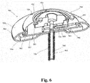
- the base member 940 also defines cutouts or detents 943, as shown for example, in FIGS. 3 , 6 , and 11 .
- the tube member 955 is coupled to the base member 940, and the base member, the hub 950 and the tube member collectively define a tether passageway 935 through which a tether (not shown) can be received.
- the tube cover member 956 can be formed with a fabric material, such as for example, Dacron®.
- the tether channel 935 intersects the locking pin channel 934 and is in fluid communication therewith.
- a portion of a top pad portion 958 is received within the channel 942 of the base member 940 as shown, for example, in FIGS. 6-8 .
- the hub 950 includes arms 961 with protrusions 962.
- the protrusions 962 can be received within cutouts 943 of the base member 940 and act as a stop or limit to the rotation of the hub 950.
- the slots 963 defined by the hub 950 enable the arms 961 to flex and allow the protrusions 962 to be moved in and out of the cutouts 943.
- the hub 950 defines a curved channel 960 on a bottom portion of the hub.
- the curved channel 960 is asymmetrical (or spiral) and receives the driver portion 946 of the locking pin assembly 926.
- the hub 950 As the hub 950 is rotated relative to the base member 940, the hub acts as a cam to move the locking pin assembly 926 linearly within the locking pin channel 934.
- the locking pin assembly 926 can be moved from a first position in which the piercing portion 949 is disposed outside of the tether passageway 935 as shown in FIGS. 5 and 6 , to a second position in which the piercing portion extends through the tether passageway 935.
- the pin member 953 see, e.g., FIG.
- the locking pin assembly 926 can be formed with a metal material that is more radio-opaque than the other components of the anchor device and thus visible to the user (e.g. physician) using conventional imaging modalities to enable the user to confirm that the locking pin assembly 926 has been fully moved to the second position.
- a tether (not shown) coupled to, for example, a prosthetic mitral valve and extending through a puncture site in the ventricular wall of a heart can be inserted through the tether passageway 935.
- the hub 950 can then be rotated 180 degrees to move the locking pin assembly 926 linearly within the locking pin channel 934 such that the piercing portion 949 extends through the tether passageway 935 and engages or pierces the tether, securing the tether to the tether attachment member 924.
- the protrusions 962 of the hub 950 are each disposed within one of the cutouts 943 of the base member 940 (i.e., a first protrusion is in a first cutout, and a second protrusion is in a second cutout).
- the hub 950 can then be rotated 180 degrees such that the protrusions 962 are moved out of the cutouts 943 of the base member 940 and at the end of the 180 degrees the protrusions are moved into the other of the cutouts of the base member ( i.e., the first protrusion is now in the second cutout, the second protrusion is now in the first cutout).
- the base member 940 can also include cutout sections 966 and define side openings 967 (see, e.g., FIGS. 3 and 4 ) that can be used to couple a delivery device to the epicardial anchor device 900.
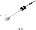
- FIG. 12 illustrates a delivery device 948 having coupling arms 968 and coupling pins (not shown) extending inwardly from the arms 968.
- the side openings 967 can receive the coupling pins and the cutout sections 966 can be engaged by the coupling arms 968.
- FIGS. 13-17 depict an epicardial anchor device 1000, similar to that described above, having a base 1040 and a rotatable hub 1050.
- Hub 1050 includes a hinged tether capture device 1070 and an actuation mechanism 1013.
- Base 1040 is similar to base 940 as described above, and further defines a recessed portion 1014 and a rim 1015, the rim being generally circular and being interrupted by the recessed portion.
- the view of anchor device 1000 shows the surface of the anchor device that faces away from the heart when the anchor device is in contact with the heart in the intended orientation.
- the tether of a prosthetic heart valve may pass through a tether passageway 1035 that extends through the base 1040 and the hub 1050.
- the tether may also pass through an opening in capture device 1070 while the capture device is in the orientation shown in FIGS. 13 and 15-16 .
- the opening in capture device 1070 may be thought of as part of the tether passageway 1035.
- the capture device 1070 may be actuated via actuation mechanism 1013 to capture the tether, with an excess length of the tether still protruding beyond the capture device 1070.
- hub 1050 may be rotated to draw the excess length of the tether within an open volume bounded by the rim 1015 so that the excess length of tether is not freely floating within the anatomy.
- capture device 1070 rotates about its hinged connection to hub 1050 in a radial direction away from the longitudinal center of the anchor device 1000, so that a portion of the capture device is received within recess 1014. With the capture device 1070 partially received within recess 1014 and having captured a portion of the excess length of the tether, rotation of hub 1050 relative to anchor 1000 also rotates a portion of the capture device 1070, and the excess length of the tether, within an interior space of the anchor device 1000.
- the structures that provide for this functionality are described in greater detail below.
- hub 1050 is positioned at the longitudinal center of epicardial anchor device 1000.
- Hub 1050 lies on top of a hub portion of a tether attachment member (not shown), similar to hub 950 of tether attachment member 924 described above.
- Hub 1050 is freely rotatable with respect to the hub portion of the tether attachment member such that rotation of the hub 1050 does not affect the rotation of the hub portion of the tether attachment member.
- Hub 1050 is recessed within anchor 1000 that receives hub 1050 such that a top surface of hub 1050 is substantially flush with a top surface of base 1040. In alternative embodiments, the top surface of hub 1050 may be recessed below the top surface of base 1040.
- the portion of the tether passageway 1035 defined by capture device 1070 is aligned with the portions of the tether passageway defined by the base 1040 and the hub 1050 when the capture device 1070 is in the non-actuated state illustrated in FIG. 13 .
- the rim 1015 defined by the base 1040 circumscribes the hub 1050, with the exception of the interruption in the rim formed by the recess 1014.
- Hub 1050 is rotatably coupled to base 1040 such that the hub may be rotated relative to the base.
- This rotatable coupling may be achieved, for example, generally similar to that described above for the rotation of hub 950 relative to base 940.
- portions of hub 1050 may be at least partially contained within base 1040, such that rotational movement may be allowed while securing the hub from being axially displaced relative to the base.
- base 1040 can be two components (not shown), a first top component and a second bottom component rotatably secured to the first component. In this manner, the second component of base 1040 can be rotated to actuate a locking pin assembly (not shown) similar to locking pin assembly 926, as described above, while hub 1050 and the first component of base 1040 remains stationary.
- Rim 1015 may be part of base 1040 and may be positioned along a substantially circular track on an interior perimeter of the base, adjacent an exterior perimeter of hub 1050, with the rim being interrupted by recess 1014.
- the rim 1015 may protrude radially inwardly from base 1040 a distance and have a rounded exterior surface along the outer circumference of the rim, however other shapes may be suitable, such as a chamfered surface, or the like.
- Recess 1014 may be spaced a distance radially away from the longitudinal center of hub 1050 greater than the distance at which the interior perimeter of the rim 1015 is spaced from the longitudinal center of the hub.
- the recess 1014 may be bounded by two opposing circumferential walls to allow for a portion of the capture device 1070 to be positioned between the opposing circumferential walls 1016, 1017 when the capture device is flipped via actuation mechanism 1013.
- rim 1015 may include a lip or prong 1018 extending downwardly (toward the surface of anchor 1000 that is intended to contact the heart), the prong defining, in part, a track or void 1012 and at least one detent 1019.
- Void 1012 may extend in a circular direction to define a circular track that is interrupted by recess 1014.
- the tip of prong 1018 does not extend entirely to the surface on which hub 1050 is positioned so that the void 1012 is accessible through the space between the tip of the prong and the surface of base 1040 on which the hub is positioned.
- the capture device 1070 when the capture device 1070 is flipped about the actuation mechanism 1013 (from the initial position shown in FIG. 15 ) so that a portion of the capture device is positioned within recess 1014, as illustrated in FIG. 17 , the prong 1018 of rim 1015 may be received within cut-outs 1072 in the capture device and detent 1019 may receive a protrusion 1074 of the capture device.
- the capture device 1070 receives a tether through tether passageway 1035, and the capture device is flipped via actuation mechanism 1013, a tether slot 1071 in the capture device captures the tether, and brings the captured portion of the tether into void 1012 as the capture device flips.
- the capture device may also rotate, with the lip or prong 1018 helping to guide the rotation of the capture device, while the captured tether is drawn into the void 1012.
- the tether may stack on top of each itself, with both the stack of excess tether loops and body portion 1073 of capture device 1070 fitting within void 1012.
- hub 1050 may continue to be rotated until protrusion 1074 is received within detent 1019, providing a tactile feedback and locking force to the hub.
- a protrusion 1074 is shown on capture device 1070, and one or more detents 1019 are shown in rim 1015, the rim may instead include one or more protrusions and the capture device may instead include a notch or detent to receive the one or more protrusions.
- Other temporary locking features such as high friction contact portions, may be provided instead of the protrusion and detent configuration described above.
- any engagement system in which the capture device 1070 may be locked in a position relative to the rim 1015 may be suitable.
- the capture device 1070 may be locked into the desired position, with an intentional rotational force on the hub 1050 being sufficient enough to move the capture device 1070 out of locking engagement with the rim 1015 to allow for the tether to be further wound (or to be unwound).
- FIG. 15 depicts a perspective view of capture device 1070 and actuation mechanism 1013 prior to the actuation mechanism being actuated to flip the capture device 1070 into recess 1014.
- Capture device 1070 may have a predominantly rectangular or cube shape with actuation mechanism 1013 adjacent to a corner of capture device 1070, with the body portion 1073 and protrusion 1074 on the opposite side of the actuation mechanism.
- alternative embodiments of capture device 1070 may include one or more rounded corners to allow for capture device 1070 to be more easily flipped.
- the protrusion 1074 may be replaced with a notch, a high friction surface, or another component of a reversible locking engagement feature.
- actuation mechanism 1013 is a button that, when pressed by the surgeon, flips capture device 1070 towards or away from recess 1014. This flipping may be performed through a spring (not shown) or other biasing mechanism attached to a portion of capture device 1070 such that actuation mechanism 1013 prevents capture device 1070 from moving until the actuation mechanism is pressed or otherwise actuated. Then, when actuation mechanism 1013 is pressed or otherwise actuated, the capture device 1070 is released so that the spring or other biasing mechanism flips the capture device 1070 so that a portion of the capture device is positioned within recess 1014. In use, capture device 1070 may be manually pushed back into its original position by the surgeon.
- Alternative actuation mechanisms may involve a lever system such that a surgeon pushing the lever in one direction pushes capture device 1070 in a direction toward/away from recess 1014 while pushing the lever in the opposite direction pushes the capture mechanism in the opposite direction.
- This lever system may be accomplished through a rod system where the lever is connected to a rod that runs through a portion of capture device 1070.
- a further alternative embodiment may involve the use of a wheel that uses a similar rod mechanism such that a surgeon may rotate the wheel one way or the other to flip capture device 1070.
- a slider may be used with the rod system such that sliding the slider flips or unflips capture device 1070.
- FIGS. 16-17 depict a method of using anchor 1000 to wind an excess length of tether 1100 to store the excess length of the tether within the void 1012 of rim 1015.
- FIG. 16 depicts the capture device 1070 in a non-actuated condition, with an excess length of tether 1100 passing through passageway 1035.
- the tether Prior to actuating the actuation mechanism 1013, the tether may be tensioned to the desired amount. When the tether is at the desired tension, it may be locked at that tension using a pin mechanism similar or identical to the locking pin assembly 926 described above.
- the tether slot 1071 may tend to grab or capture the tether due to the relative positions of the tether slot and the tether. However, the surgeon may manually place the excess length of tether 1100 within the capture slot 1071 to help ensure the tether is appropriately captured when the capture device 1070 is flipped. Actuation mechanism 1013 may then be actuated by the surgeon, for example as described above, to flip the capture device 1070 into recess 1014, with the excess length of tether 1100 being drawn into the recess due to capture slot 1071 capturing and forcing a portion of the tether to move along with the capture device.
- the surgeon may rotate hub 1050 in a clockwise or counter-clockwise direction such that body portion 1073 is received within void 1012 and prong 1018 is received within cut-outs 1072.
- the hub 1050 may be rotated until excess tether 1100 has been sufficiently wound, at which point the surgeon may lock the hub 1050 to prevent the hub from being unintentionally rotated and the excess tether being inadvertently unwound.
- hub 1050 may be further rotated so that protrusion 1074 is engaged with detent 1019.
- Such an engagement provides a tactile feedback and locking force to hub 1050 to prevent hub 1050 and excess tether 1100 from being unintentionally unwound from prong 1018.
- a plurality of detents 1019 may be provided at regular (or irregular) intervals along the circumference of the underside of rim 1015 such that multiple options are provided regarding where the capture device 1070 may reversibly lock to the rim 1015.
- securing hub 1050 to rim 1015 may include having the contact surfaces between body portion 1073 and the rim 1015 and/or prong 1018 be textured to provide a frictional force between the two contacting surfaces.
- the prosthetic heart valve is in place and the tether is tensioned to the desired amount, with the excess length of the tether being wound within anchor device 1000 so that the excess length does not need to be physically cut away.
- the tether may be unwound so that the tether may be re-tensioned, or the anchor 1000 may be removed and the tether may be used as a rail to access the prosthetic heart valve to re-collapse the valve and remove it from the patient.
- the surgeon gains access to the anchor 1000 and rotates the hub 1050 in a direction opposite to the direction the surgeon rotated the hub when winding the tether.
- the surgeon may rotate the hub in a clockwise direction to unwind the tether.
- the hub 1050 may be rotated with a sufficient force to overcome the reversible locking force between the engagement of protrusion 1074 and detent 1019 such that the protrusion disengages with detent 1019 and the capture device 1070 is again positioned within recess 1014.
- the surgeon may actuate actuation mechanism 1013 to flip the capture device 1070 back to its initial position, as shown in FIG. 16 .
- the surgeon may manually flip the capture device 1070 back to its initial position. The surgeon may then re-tension the tether, or otherwise remove the anchor 1000 from the tether entirely and advance a separate device over the tether and into the heart in order to re-collapse the prosthetic heart valve into that device for explantation.
- an epicardial anchor system comprises:
- a method of using an epicardial anchor comprising:
- an epicardial anchor system comprising:
Abstract
An epicardial anchor system comprising a tether attachment member defining a portion of a tether passageway configured to receive a portion of a tether extending from a heart valve, a base having a rim defining a void along a circumference of the rim, and a tether capture device adjacent the tether attachment member and hingedly attached to the epicardial anchor, the tether capture device including an opening configured to receive the portion of the tether therethrough and a slot configured to capture the portion of the tether extending through the opening, and an actuation mechanism configured to flip the tether capture device from an unactuated condition to an actuated condition, wherein in the unactuated condition, the tether capture device is spaced from the void defined by the rim, and in the actuated condition, a first portion of the tether capture device is positioned within the void defined by the rim.
Description
- The present disclosure relates to devices and methods for securing a tether of a prosthetic heart valve to an anchor device.
- Various options are available to maintain a prosthetic heart valve in a desired position within a native heart valve annulus of a patient. For example, the position of a surgical prosthetic heart valve may be maintained by suturing the prosthetic heart valve into the patient's native heart valve annulus. Collapsible and expandable prosthetic heart valves, on the other hand, may be maintained in a desired position by exerting radial forces against the native heart valve annulus and/or surrounding tissue. It may additionally be beneficial to assist collapsible and expandable prosthetic heart valves in maintaining the desired position through the use of a tether that extends from the prosthetic heart valve to an anchor on an exterior portion of the patient's heart. However, during or after the surgery, the tension on the tether and the position of the prosthetic heart valve may need to be readjusted, for example, if the prosthetic heart valve deviates from its intended position, or if the tension on the tether changes for any reason.
- Thus, it would be preferable for a tether and the corresponding anchor to allow for post-surgical modifications to adjust the tension of the tether, or otherwise to adjust the position of the prosthetic heart valve post-surgery.
- One aspect of the disclosure provides for an epicardial anchor system comprising a tether attachment member defining a portion of a tether passageway configured to receive a portion of a tether extending from a prosthetic heart valve, a base having a rim defining a void along a circumference of the rim, and a tether capture device adjacent the tether attachment member and hingedly attached to the epicardial anchor, the tether capture device including an opening configured to receive the portion of the tether therethrough and a slot configured to capture the portion of the tether extending through the opening, and an actuation mechanism configured to flip the tether capture device from an unactuated condition to an actuated condition, wherein in the unactuated condition, the tether capture device is spaced from the void defined by the rim, and in the actuated condition, a first portion of the tether capture device is positioned within the void defined by the rim.
- Another aspect of the disclosure provides for a method of using an epicardial anchor comprising receiving a portion of a tether of a prosthetic heart valve within an opening of a tether capture device of the epicardial anchor while the prosthetic heart valve is positioned within a patient's heart, actuating an actuation mechanism to flip the tether capture device so that a first portion of the tether capture device is received within a recess defined by a rim, the rim defined by a base of the epicardial anchor device, the recess interrupting a circumference of the rim, and capturing the portion of the tether in the recess upon actuation of the tether capture device.
- Another aspect of the disclosure provides for an epicardial anchor system comprising a tether configured to extend from a prosthetic heart valve, a tether attachment member defining a portion of a tether passageway configured to receive a portion of the tether, a base having a rim defining a void along a circumference of the rim, and a tether capture device adjacent the tether attachment member and hingedly attached to the epicardial anchor, the tether capture device including an opening configured to receive the portion of the tether therethrough and a slot configured to capture the portion of the tether extending through the opening, and an actuation mechanism configured to flip the tether capture device from an unactuated condition to an actuated condition, wherein in the unactuated condition, the tether capture device is spaced from the void defined by the rim, and in the actuated condition, a first portion of the tether capture device is positioned within the void defined by the rim.
- These and other features, aspects, and advantages of the present disclosure will become better understood with regard to the following description, and accompanying drawings.
-
FIG. 1 depicts a cross-sectional illustration of a portion of a heart with a prosthetic mitral valve implanted therein and an epicardial anchor device anchoring the mitral valve in position. -
FIG. 2 depicts a schematic illustration of an epicardial anchor device, according to an embodiment of the present disclosure. -
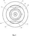
FIG. 3 depicts a perspective view of an epicardial anchor, according to an embodiment of the present disclosure. -
FIG. 4 depicts a top view of the epicardial anchor ofFIG. 3 . -
FIG. 5 depicts an exploded view of the epicardial anchor ofFIG. 3 . -
FIG. 6 depicts a perspective cross-sectional view of the epicardial anchor ofFIG. 3 . -
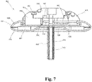
FIG. 7 depicts a front cross-sectional view of the epicardial anchor ofFIG. 3 . -
FIG. 8 depicts a perspective cross-sectional view of the epicardial anchor ofFIG. 3 . -
FIG. 9 depicts a top perspective view of a hub of the epicardial anchor ofFIG. 3 . -
FIG. 10 depicts a bottom perspective view of a hub of the epicardial anchor ofFIG. 3 . -
FIG. 11 depicts a top partial view of the epicardial anchor ofFIG. 3 . -
FIG. 12 depicts a perspective view of a delivery device engaged with the epicardial anchor ofFIG. 3 . -
FIG. 13 depicts a top view of an epicardial anchor according to an embodiment of the present disclosure. -
FIG. 14 depicts a cross-sectional view of a rim of the epicardial anchor ofFIG. 13 . -
FIG. 15 depicts a perspective view of a capture device of the epicardial anchor ofFIG. 13 . -
FIG. 16 depicts a perspective view of excess tether received in the capture device ofFIG. 15 . -
FIG. 17 depicts a cross-sectional view of the capture device received within the rim of epicardial anchor ofFIG. 13 . - Some devices for anchoring a medical device, such as a collapsible and expandable prosthetic heart valve, can include securing one or more tethers extending from the medical device to an anchor positioned on the heart, such as along an exterior portion of the ventricular wall. In one exemplary valve replacement procedure, the prosthetic heart valve may be delivered to a native valve annulus while in a collapsed state, and then allowed to expand to at least partially secure the prosthetic heart valve within the native valve annulus. If the prosthetic heart valve is for use in replacing a native mitral valve, a flared inflow end of the prosthetic heart valve may help prevent migration of the prosthetic heart valve into the left ventricle, while a tether attached to the prosthetic heart valve may assist in preventing migration of the prosthetic heart valve into the left atrium. During implantation, while the prosthetic heart valve is positioned within the valve annulus, a first end of the tether may be coupled to the prosthetic heart valve, and a second end of the tether may exit the heart, for example via a puncture in the left ventricular apex. While the second end of the tether is positioned outside the heart, an anchor may be slid over the tether until the anchor sits along the exterior portion of the ventricular wall such that an excess portion of the tether extends past the anchor outside the heart. The tether may then be tensioned until the prosthetic heart valve is at a desired tension and position within the patient's heart valve annulus. Once that desired tension is reached, the tether may be fixed to the anchor and the excess portion of the tether may be cut off and removed, thereby preventing excess length of the tether from freely floating within the patient's body and potentially interfering with the patient's surrounding anatomy.
- However, after removal of the excess portion of the tether, there may be a desire to re-tension the tether. For example, such additional tensioning may be desirable if the prosthetic heart valve is not implanted in a desired position during surgery, or if the position shifts after surgery. Alternatively, tension readjustment may be desired after the surgery is complete and an interval of time has lapsed. In such an instance, the prosthetic heart valve may have been repositioned through wear or unintentional position shifts, or the native heart anatomy may have adjusted. For example, the tension on the tether may cause the ventricular wall to change shape, which in turn may reduce the tension of the tether. This biological adaption by the patient's heart can compound the need for an easily and quickly accessible means of adjusting the tether's tension as there is typically only a certain window of time (e.g., a few weeks, months, or the like) after implantation to perform such an adjustment, prior to tissue in-growth occurring in enough quantity to make further adjustment difficult or impossible. However, such an adjustment may be difficult or impossible if the excess portion of the tether has been cut off during surgery, as tensioning tools may require a certain length of tether extending from the anchor in order to properly grasp and apply a tensioning force. Thus, it may be beneficial to avoid cutting excess tether length to allow the excess tether portion to be accessed and retrieved, while simultaneously avoiding the excess tether length freely drifting within the patient.
-
FIG. 1 is a cross-sectional illustration of the left ventricle LV and left atrium LA of a heart having a transcatheter prosthetic mitral valve PMV deployed therein and an epicardial anchor device EAD as described herein securing the prosthetic mitral valve in place.FIG. 1 illustrates the prosthetic mitral valve PMV seated into the native annulus NA of the valve and held there using a valve frame VF of the prosthetic mitral valve, the radial tension from the native leaflets, and a ventricular tether T secured with attachment portions Tp to the prosthetic mitral valve and to the epicardial anchor EAD. An atrial flare portion (not separately labeled) of the valve frame VF may be positioned in the left atrium LA of the heart to prevent migration of the prosthetic mitral valve PMV into the left ventricle LV. Various embodiments of an epicardial anchor device are described in more detail below with reference to specific embodiments. -
FIG. 2 is a schematic illustration of an epicardial anchor device 100 (also referred to herein as "anchor," "anchor device," or "epicardial anchor") according to an embodiment of the disclosure. Theanchor device 100 can be used to anchor or secure a prosthetic mitral valve PMV deployed between the left atrium LA and left ventricle LV of a heart. Theanchor device 100 can be used, for example, to anchor or secure the prosthetic mitral valve PMV via atether 128 as described above with respect toFIG. 1 . Theanchor device 100 can also seal a puncture formed in the ventricular wall (not shown inFIG. 2 ) of the heart during implantation of the prosthetic mitral valve PMV. Theanchor device 100 can also be used in other applications to anchor a medical device (such as any prosthetic atrioventricular valve, including the tricuspid valve, or other heart valve) and/or to seal an opening such as a puncture. - The
anchor device 100 can include a pad (or pad assembly) 120, atether attachment member 124 and alocking pin 126. In some embodiments, theanchor device 100 can include a sleeve gasket (not shown inFIG. 2 ). Thepad 120 can contact the epicardial surface of the heart and can be constructed of any suitable biocompatible surgical material. Thepad 120 can be used to assist the sealing of a surgical puncture formed when implanting a prosthetic mitral valve. In some embodiments, thepad 120 can include a slot that extends radially to an edge of the pad such that the pad can be attached to, or disposed about, thetether 128 by sliding the pad onto the tether via the slot. - In some embodiments, the
pad 120 can be made with a double velour material to promote ingrowth of the pad into the puncture site area. For example, pad or felt pledgets can be made of a felted polyester and may be cut to any suitable size or shape, such as those available from Bard® as PTFE Felt Pledgets having a nominal thickness of 2.87 mm. In some embodiments, thepad 120 can be larger in diameter than thetether attachment member 124. Thepad 120 can have a circular or disk shape, or other suitable shapes. - The
tether attachment member 124 can provide the anchoring and mounting platform to which one ormore tethers 128 can be coupled (e.g., tied or pinned). Thetether attachment member 124 can include a base member (not shown) that defines at least a portion of a tether passageway (not shown) through which thetether 128 can be received and pass through the tether attachment member, and a locking pin channel (not shown) through which thelocking pin 126 can be received. The locking pin channel can be in fluid communication with the tether passageway such that when thelocking pin 126 is disposed in the locking pin channel, the locking pin can contact or pierce thetether 128 as the tether passes through the tether passageway as described in more detail below with reference to specific embodiments. - The
locking pin 126 can be used to hold thetether 128 in place after theanchor device 100 has been tightened against the ventricular wall and the tether has been pulled to a desired tension. For example, thetether 128 can extend through a hole in thepad 120, through a hole in a sleeve gasket (if the anchor device includes a sleeve gasket), and through the tether passageway of thetether attachment member 124. Thelocking pin 126 can be inserted or moved within the locking pin channel such that it pierces or otherwise engages thetether 128 as the tether extends through the tether passageway of thetether attachment member 124. Thus, the lockingpin 126 can intersect thetether 128 and secure the tether to thetether attachment member 124. - The
tether attachment member 124 can be formed with one or more of a variety of suitable biocompatible materials. For example, in some embodiments, thetether attachment member 124 can be made of polyethylene, or other hard or semi-hard polymer, and can be covered with a polyester velour to promote ingrowth. In other embodiments, thetether attachment member 124 can be made of metal, such as, for example, Nitinol®, or ceramic materials. Thetether attachment member 124 can be various sizes and/or shapes. For example, thetether attachment member 124 can be substantially disk shaped. - In some embodiments, the
tether attachment member 124 can include a hub that is movably coupled to the base member of a tether attachment member. The hub can define a channel that can receive a portion of the locking pin (or locking pin assembly) 126 such that as the hub is rotated, the hub acts as a cam to move thelocking pin 126 linearly within the locking pin channel. In this manner, the lockingpin 126 is moved from a first position in which the locking pin is spaced from the tether passageway to a second position in which the locking pin intersects the tether passageway and engages or pierces a portion of the tether. - In use, after a prosthetic mitral valve PMV has been placed within a heart, the tether extending from the prosthetic mitral valve can be inserted into the tether passageway of the
anchor device 100 and the tension on thetether attachment member 124 can be adjusted to a desired tension. Alternatively, in some cases, the tether extending from the prosthetic mitral valve PMV can be coupled to theanchor device 100 prior to the prosthetic mitral valve being placed within the heart. The anchor device 100 (e.g., some portion of the anchor device such as thetether attachment member 124, or a lever arm, or hub depending on the particular embodiment) can be actuated such that thelocking pin 126 intersects the tether passageway and engages a portion of thetether 128 disposed within the tether passageway, securing the tether to the tether attachment member. In some embodiments, prior to inserting thetether 128 into the tether passageway, theanchor device 100 can be actuated to configure the anchor device to receive the tether. For example, if thetether attachment member 124 includes a lever arm movably coupled to the base member, the lever arm may need to be moved to an open position to allow the tether to be inserted into the tether passageway. -
FIGS. 3-11 depict anexemplary anchor device 900 capable of being used in conjunction with prosthetic mitral and tricuspid valves, including those disclosed inU.S. Patent App. Pub. No. 2016/0143736 , the disclosure of which is hereby incorporated by reference herein. Theepicardial anchor device 900 includes atether attachment member 924, apad assembly 920, atube member 955 and atube cover member 956. Thetether attachment member 924 includes abase member 940, ahub 950, a retainingring 952, a lockingpin assembly 926, and apin member 953. The lockingpin assembly 926 includes adriver portion 946 and a piercingportion 949. Thebase member 940 defines acircumferential pad channel 942, a retainingchannel 951 and alocking pin channel 934. Thepad channel 942 can be used to couple thepad assembly 920 to thetether attachment member 924. The retainingchannel 951 can receive an outer edge of the retainingring 952, which is used to retain thehub 950 to thebase member 940. Thebase member 940 also defines cutouts ordetents 943, as shown for example, inFIGS. 3 ,6 , and11 . - The
tube member 955 is coupled to thebase member 940, and the base member, thehub 950 and the tube member collectively define atether passageway 935 through which a tether (not shown) can be received. Thetube cover member 956 can be formed with a fabric material, such as for example, Dacron®. Thetether channel 935 intersects thelocking pin channel 934 and is in fluid communication therewith. A portion of atop pad portion 958 is received within thechannel 942 of thebase member 940 as shown, for example, inFIGS. 6-8 . - An outer perimeter portion of the
hub 950 is received within the retainingchannel 951 such that the hub can rotate relative to thebase member 940 to actuate the lockingpin assembly 926 as described in more detail below. As shown, for example, inFIG. 9 , thehub 950 includesarms 961 withprotrusions 962. Theprotrusions 962 can be received withincutouts 943 of thebase member 940 and act as a stop or limit to the rotation of thehub 950. Theslots 963 defined by thehub 950 enable thearms 961 to flex and allow theprotrusions 962 to be moved in and out of thecutouts 943. As shown, for example, inFIGS. 8 and9 , thehub 950 defines acurved channel 960 on a bottom portion of the hub. Thecurved channel 960 is asymmetrical (or spiral) and receives thedriver portion 946 of the lockingpin assembly 926. As thehub 950 is rotated relative to thebase member 940, the hub acts as a cam to move the lockingpin assembly 926 linearly within thelocking pin channel 934. The lockingpin assembly 926 can be moved from a first position in which the piercingportion 949 is disposed outside of thetether passageway 935 as shown inFIGS. 5 and6 , to a second position in which the piercing portion extends through thetether passageway 935. The pin member 953 (see, e.g.,FIG. 7 ) can be formed with a metal material that is more radio-opaque than the other components of the anchor device and thus visible to the user (e.g. physician) using conventional imaging modalities to enable the user to confirm that the lockingpin assembly 926 has been fully moved to the second position. - In use, when the locking
pin assembly 926 is in the first position, a tether (not shown) coupled to, for example, a prosthetic mitral valve and extending through a puncture site in the ventricular wall of a heart can be inserted through thetether passageway 935. Thehub 950 can then be rotated 180 degrees to move the lockingpin assembly 926 linearly within thelocking pin channel 934 such that the piercingportion 949 extends through thetether passageway 935 and engages or pierces the tether, securing the tether to thetether attachment member 924. For example, when the locking pin is in the first position, theprotrusions 962 of thehub 950 are each disposed within one of thecutouts 943 of the base member 940 (i.e., a first protrusion is in a first cutout, and a second protrusion is in a second cutout). Thehub 950 can then be rotated 180 degrees such that theprotrusions 962 are moved out of thecutouts 943 of thebase member 940 and at the end of the 180 degrees the protrusions are moved into the other of the cutouts of the base member (i.e., the first protrusion is now in the second cutout, the second protrusion is now in the first cutout). - The
base member 940 can also includecutout sections 966 and define side openings 967 (see, e.g.,FIGS. 3 and4 ) that can be used to couple a delivery device to theepicardial anchor device 900. For example,FIG. 12 illustrates adelivery device 948 havingcoupling arms 968 and coupling pins (not shown) extending inwardly from thearms 968. Theside openings 967 can receive the coupling pins and thecutout sections 966 can be engaged by the couplingarms 968. - In another embodiment,
FIGS. 13-17 depict anepicardial anchor device 1000, similar to that described above, having abase 1040 and arotatable hub 1050.Hub 1050 includes a hingedtether capture device 1070 and anactuation mechanism 1013.Base 1040 is similar tobase 940 as described above, and further defines a recessedportion 1014 and arim 1015, the rim being generally circular and being interrupted by the recessed portion. Referring toFIG. 13 , the view ofanchor device 1000 shows the surface of the anchor device that faces away from the heart when the anchor device is in contact with the heart in the intended orientation. Generally, the tether of a prosthetic heart valve may pass through atether passageway 1035 that extends through thebase 1040 and thehub 1050. During the process of tensioning and securing the tether to theanchor device 1000, the tether may also pass through an opening incapture device 1070 while the capture device is in the orientation shown inFIGS. 13 and15-16 . The opening incapture device 1070 may be thought of as part of thetether passageway 1035. When the desired tension on the tether is achieved, thecapture device 1070 may be actuated viaactuation mechanism 1013 to capture the tether, with an excess length of the tether still protruding beyond thecapture device 1070. Then,hub 1050 may be rotated to draw the excess length of the tether within an open volume bounded by therim 1015 so that the excess length of tether is not freely floating within the anatomy. When actuated byactuation mechanism 1013,capture device 1070 rotates about its hinged connection tohub 1050 in a radial direction away from the longitudinal center of theanchor device 1000, so that a portion of the capture device is received withinrecess 1014. With thecapture device 1070 partially received withinrecess 1014 and having captured a portion of the excess length of the tether, rotation ofhub 1050 relative to anchor 1000 also rotates a portion of thecapture device 1070, and the excess length of the tether, within an interior space of theanchor device 1000. The structures that provide for this functionality are described in greater detail below. - As shown in
FIG. 13 ,hub 1050 is positioned at the longitudinal center ofepicardial anchor device 1000.Hub 1050 lies on top of a hub portion of a tether attachment member (not shown), similar tohub 950 oftether attachment member 924 described above.Hub 1050 is freely rotatable with respect to the hub portion of the tether attachment member such that rotation of thehub 1050 does not affect the rotation of the hub portion of the tether attachment member.Hub 1050 is recessed withinanchor 1000 that receiveshub 1050 such that a top surface ofhub 1050 is substantially flush with a top surface ofbase 1040. In alternative embodiments, the top surface ofhub 1050 may be recessed below the top surface ofbase 1040. The portion of thetether passageway 1035 defined bycapture device 1070 is aligned with the portions of the tether passageway defined by thebase 1040 and thehub 1050 when thecapture device 1070 is in the non-actuated state illustrated inFIG. 13 . - Referring now to
FIGS. 13 and14 , therim 1015 defined by thebase 1040 circumscribes thehub 1050, with the exception of the interruption in the rim formed by therecess 1014.Hub 1050 is rotatably coupled to base 1040 such that the hub may be rotated relative to the base. This rotatable coupling may be achieved, for example, generally similar to that described above for the rotation ofhub 950 relative tobase 940. For instance, portions ofhub 1050 may be at least partially contained withinbase 1040, such that rotational movement may be allowed while securing the hub from being axially displaced relative to the base. In an alternative aspect,base 1040 can be two components (not shown), a first top component and a second bottom component rotatably secured to the first component. In this manner, the second component of base 1040 can be rotated to actuate a locking pin assembly (not shown) similar to lockingpin assembly 926, as described above, whilehub 1050 and the first component of base 1040 remains stationary. - A cross-section of
rim 1015 is illustrated inFIG. 14 .Rim 1015 may be part ofbase 1040 and may be positioned along a substantially circular track on an interior perimeter of the base, adjacent an exterior perimeter ofhub 1050, with the rim being interrupted byrecess 1014. Therim 1015 may protrude radially inwardly from base 1040 a distance and have a rounded exterior surface along the outer circumference of the rim, however other shapes may be suitable, such as a chamfered surface, or the like.Recess 1014 may be spaced a distance radially away from the longitudinal center ofhub 1050 greater than the distance at which the interior perimeter of therim 1015 is spaced from the longitudinal center of the hub. Therecess 1014 may be bounded by two opposing circumferential walls to allow for a portion of thecapture device 1070 to be positioned between the opposingcircumferential walls actuation mechanism 1013. - Still referring to
FIG. 14 ,rim 1015 may include a lip orprong 1018 extending downwardly (toward the surface ofanchor 1000 that is intended to contact the heart), the prong defining, in part, a track or void 1012 and at least onedetent 1019.Void 1012 may extend in a circular direction to define a circular track that is interrupted byrecess 1014. The tip ofprong 1018 does not extend entirely to the surface on whichhub 1050 is positioned so that thevoid 1012 is accessible through the space between the tip of the prong and the surface ofbase 1040 on which the hub is positioned. In alternative embodiments, there may be any number ofdetents 1019 alongtrack 1012 ofprong 1018. - With this configuration, when the
capture device 1070 is flipped about the actuation mechanism 1013 (from the initial position shown inFIG. 15 ) so that a portion of the capture device is positioned withinrecess 1014, as illustrated inFIG. 17 , theprong 1018 ofrim 1015 may be received within cut-outs 1072 in the capture device anddetent 1019 may receive aprotrusion 1074 of the capture device. As is described in greater detail below, when thecapture device 1070 receives a tether throughtether passageway 1035, and the capture device is flipped viaactuation mechanism 1013, atether slot 1071 in the capture device captures the tether, and brings the captured portion of the tether into void 1012 as the capture device flips. After thecapture device 1070 is flipped, and thehub 1050 is rotated, the capture device may also rotate, with the lip orprong 1018 helping to guide the rotation of the capture device, while the captured tether is drawn into thevoid 1012. In this manner, where the excess tether is looped multiple times withinvoid 1012, the tether may stack on top of each itself, with both the stack of excess tether loops andbody portion 1073 ofcapture device 1070 fitting withinvoid 1012. Once a desired amount of excess tether has been looped withinvoid 1012,hub 1050 may continue to be rotated untilprotrusion 1074 is received withindetent 1019, providing a tactile feedback and locking force to the hub. It should be understood that although aprotrusion 1074 is shown oncapture device 1070, and one ormore detents 1019 are shown inrim 1015, the rim may instead include one or more protrusions and the capture device may instead include a notch or detent to receive the one or more protrusions. Other temporary locking features, such as high friction contact portions, may be provided instead of the protrusion and detent configuration described above. In fact, any engagement system in which thecapture device 1070 may be locked in a position relative to therim 1015 may be suitable. Preferably, whatever engagement system is used, thecapture device 1070 may be locked into the desired position, with an intentional rotational force on thehub 1050 being sufficient enough to move thecapture device 1070 out of locking engagement with therim 1015 to allow for the tether to be further wound (or to be unwound). -
FIG. 15 depicts a perspective view ofcapture device 1070 andactuation mechanism 1013 prior to the actuation mechanism being actuated to flip thecapture device 1070 intorecess 1014.Capture device 1070 may have a predominantly rectangular or cube shape withactuation mechanism 1013 adjacent to a corner ofcapture device 1070, with thebody portion 1073 andprotrusion 1074 on the opposite side of the actuation mechanism. However, alternative embodiments ofcapture device 1070 may include one or more rounded corners to allow forcapture device 1070 to be more easily flipped. In further alternative embodiments, there may be noprotrusion 1074. Or, as noted above, theprotrusion 1074 may be replaced with a notch, a high friction surface, or another component of a reversible locking engagement feature. - In a preferred embodiment,
actuation mechanism 1013 is a button that, when pressed by the surgeon, flipscapture device 1070 towards or away fromrecess 1014. This flipping may be performed through a spring (not shown) or other biasing mechanism attached to a portion ofcapture device 1070 such thatactuation mechanism 1013 preventscapture device 1070 from moving until the actuation mechanism is pressed or otherwise actuated. Then, whenactuation mechanism 1013 is pressed or otherwise actuated, thecapture device 1070 is released so that the spring or other biasing mechanism flips thecapture device 1070 so that a portion of the capture device is positioned withinrecess 1014. In use,capture device 1070 may be manually pushed back into its original position by the surgeon. This may be useful if the user needs to reverse the process of winding the tether, and it is desired to readjust the tension on the tether. Alternative actuation mechanisms may involve a lever system such that a surgeon pushing the lever in one direction pushescapture device 1070 in a direction toward/away fromrecess 1014 while pushing the lever in the opposite direction pushes the capture mechanism in the opposite direction. This lever system may be accomplished through a rod system where the lever is connected to a rod that runs through a portion ofcapture device 1070. A further alternative embodiment may involve the use of a wheel that uses a similar rod mechanism such that a surgeon may rotate the wheel one way or the other to flipcapture device 1070. In yet another embodiment, a slider may be used with the rod system such that sliding the slider flips orunflips capture device 1070. -
FIGS. 16-17 depict a method of usinganchor 1000 to wind an excess length oftether 1100 to store the excess length of the tether within thevoid 1012 ofrim 1015.FIG. 16 depicts thecapture device 1070 in a non-actuated condition, with an excess length oftether 1100 passing throughpassageway 1035. Prior to actuating theactuation mechanism 1013, the tether may be tensioned to the desired amount. When the tether is at the desired tension, it may be locked at that tension using a pin mechanism similar or identical to the lockingpin assembly 926 described above. - When actuating
actuation mechanism 1013, as thecapture device 1070 begins to flip, thetether slot 1071 may tend to grab or capture the tether due to the relative positions of the tether slot and the tether. However, the surgeon may manually place the excess length oftether 1100 within thecapture slot 1071 to help ensure the tether is appropriately captured when thecapture device 1070 is flipped.Actuation mechanism 1013 may then be actuated by the surgeon, for example as described above, to flip thecapture device 1070 intorecess 1014, with the excess length oftether 1100 being drawn into the recess due tocapture slot 1071 capturing and forcing a portion of the tether to move along with the capture device. With thecapture device 1070 positioned at least partially withinrecess 1014, the surgeon may rotatehub 1050 in a clockwise or counter-clockwise direction such thatbody portion 1073 is received withinvoid 1012 andprong 1018 is received within cut-outs 1072. As thehub 1050 is rotated and thecapture device 1070 rotates with respect torim 1015, the excess length oftether 1100 is drawn into the void 1012 causing the tether to wind within thebase 1070. Thehub 1050 may be rotated untilexcess tether 1100 has been sufficiently wound, at which point the surgeon may lock thehub 1050 to prevent the hub from being unintentionally rotated and the excess tether being inadvertently unwound. - Once a sufficient amount of
excess tether 1100 has been wound withinvoid 1012,hub 1050 may be further rotated so thatprotrusion 1074 is engaged withdetent 1019. Such an engagement provides a tactile feedback and locking force tohub 1050 to preventhub 1050 andexcess tether 1100 from being unintentionally unwound fromprong 1018. A plurality ofdetents 1019 may be provided at regular (or irregular) intervals along the circumference of the underside ofrim 1015 such that multiple options are provided regarding where thecapture device 1070 may reversibly lock to therim 1015. Each time theprotrusion 1074 encounters acorresponding detent 1019, the surgeon may receive feedback in the form of a tactile and/or audible "click." As noted above, alternative embodiments of securinghub 1050 torim 1015 may include having the contact surfaces betweenbody portion 1073 and therim 1015 and/orprong 1018 be textured to provide a frictional force between the two contacting surfaces. - At this point, the prosthetic heart valve is in place and the tether is tensioned to the desired amount, with the excess length of the tether being wound within
anchor device 1000 so that the excess length does not need to be physically cut away. - If it is desired to re-tension the tether, or even to remove the prosthetic heart valve, at any point prior to significant tissue in-growth occurring, the tether may be unwound so that the tether may be re-tensioned, or the
anchor 1000 may be removed and the tether may be used as a rail to access the prosthetic heart valve to re-collapse the valve and remove it from the patient. To unwind the tether, the surgeon gains access to theanchor 1000 and rotates thehub 1050 in a direction opposite to the direction the surgeon rotated the hub when winding the tether. For instance, if the surgeon rotatedhub 1050 in a counter-clockwise direction to wind the tether, the surgeon may rotate the hub in a clockwise direction to unwind the tether. Thehub 1050 may be rotated with a sufficient force to overcome the reversible locking force between the engagement ofprotrusion 1074 anddetent 1019 such that the protrusion disengages withdetent 1019 and thecapture device 1070 is again positioned withinrecess 1014. Oncehub 1050 has been rotated to unwind the excess length oftether 1100, and thecapture device 1070 is positioned withinrecess 1014, the surgeon may actuateactuation mechanism 1013 to flip thecapture device 1070 back to its initial position, as shown inFIG. 16 . In certain embodiments, instead of actuating theactuation mechanism 1013, the surgeon may manually flip thecapture device 1070 back to its initial position. The surgeon may then re-tension the tether, or otherwise remove theanchor 1000 from the tether entirely and advance a separate device over the tether and into the heart in order to re-collapse the prosthetic heart valve into that device for explantation. - According to one aspect of the disclosure, an epicardial anchor system comprises:
- a tether attachment member defining a portion of a tether passageway configured to receive a portion of a tether extending from a prosthetic heart valve;
- a base having a rim defining a void along a circumference of the rim;
- a tether capture device adjacent the tether attachment member and hingedly attached to the epicardial anchor, the tether capture device including an opening configured to receive the portion of the tether therethrough and a slot configured to capture the portion of the tether extending through the opening; and
- an actuation mechanism configured to flip the tether capture device from an unactuated condition to an actuated condition,
- wherein in the unactuated condition, the tether capture device is spaced from the void defined by the rim, and in the actuated condition, a first portion of the tether capture device is positioned within the void defined by the rim; and/or
- the tether capture device is positioned on top of the tether attachment member and/or
- the epicardial anchor includes a locking pin configured to secure the tether to the tether attachment member at a desired tension; and/or
- the base defines a recess along the circumference of the rim, the recess being sized and shaped to receive the first portion of the tether capture device following actuation of the actuation device; and/or
- the epicardial anchor has a top surface and the tether capture device has a top surface recessed with respect to the top surface of the epicardial anchor; and/or
- the actuation mechanism is adjacent a second portion of the tether capture device, the second portion being opposite the first portion; and/or
- the actuation mechanism is a button, a lever, or a wheel; and/or
- the rim further includes a prong and the tether capture device includes a cut-out, the cut-out being sized and shaped to receive the prong therein; and/or
- the rim has a detent and the first portion of the capture device has a protrusion configured to be received in the detent in a reversible locking engagement; and/or
- the detent includes a plurality of detents positioned at intervals around the circumference of the rim.
- According to another aspect of the disclosure, a method of using an epicardial anchor comprising:
- receiving a portion of a tether of a prosthetic heart valve within an opening of a tether capture device of the epicardial anchor while the prosthetic heart valve is positioned within a patient's heart;
- actuating an actuation mechanism to flip the tether capture device so that a first portion of the tether capture device is received within a recess defined by a rim, the rim defined by a base of the epicardial anchor device, the recess interrupting a circumference of the rim; and
- capturing the portion of the tether in the recess upon actuation of the tether capture device; and/or
- the rim defines a void extending along the circumference of the rim, and the tether capture device is coupled to a hub of the epicardial anchor; and/or
- rotating the hub in a first direction to cause the tether capture device to travel circumferentially along the void, an excess length of the tether being wound into the void as the hub is rotated; and/or
- the rim defines a prong and the tether capture device defines a cut-out, the prong being received within the cut-out as the tether capture device travels circumferentially along the void; and/or
- rotating a hub in a second direction opposite the first direction after rotating the hub in the first direction, wherein rotating the hub in the second direction unwinds the excess length of the tether from the void; and/or
- locking the tether capture device in a desired position within the void to prevent unintentional movement of the tether capture device within the void; and/or
- locking the tether capture device includes engaging a protrusion of the tether capture device with a detent along the rim; and/or
- securing the tether to the epicardial anchor with a locking pin when the tether is at a desired tension; and/or
- the actuation mechanism is a button, a lever or a wheel.
- According to another aspect of the disclosure, an epicardial anchor system comprising:
- a tether configured to extend from a prosthetic heart valve;
- a tether attachment member defining a portion of a tether passageway configured to receive a portion of the tether;
- a base having a rim defining a void along a circumference of the rim;
- a tether capture device adjacent the tether attachment member and hingedly attached to the epicardial anchor, the tether capture device including an opening configured to receive the portion of the tether therethrough and a slot configured to capture the portion of the tether extending through the opening; and
- an actuation mechanism configured to flip the tether capture device from an unactuated condition to an actuated condition,
- wherein in the unactuated condition, the tether capture device is spaced from the void defined by the rim, and in the actuated condition, a first portion of the tether capture device is positioned within the void defined by the rim.
- Although the invention herein has been described with reference to particular embodiments, it is to be understood that these embodiments are merely illustrative of the principles and applications of the present invention. It is therefore to be understood that numerous modifications may be made to the illustrative embodiments and that other arrangements may be devised without departing from the spirit and scope of the present invention as defined by the appended claims.
Claims (15)
- An epicardial anchor system comprising:a tether attachment member defining a portion of a tether passageway configured to receive a portion of a tether extending from a prosthetic heart valve;a base having a rim defining a void along a circumference of the rim;a tether capture device adjacent the tether attachment member and hingedly attached to the epicardial anchor, the tether capture device including an opening configured to receive the portion of the tether therethrough and a slot configured to capture the portion of the tether extending through the opening; andan actuation mechanism configured to flip the tether capture device from an unactuated condition to an actuated condition,wherein in the unactuated condition, the tether capture device is spaced from the void defined by the rim, and in the actuated condition, a first portion of the tether capture device is positioned within the void defined by the rim.
- The system of claim 1, wherein the tether capture device is positioned on top of the tether attachment member.
- The system of claims 1 or 2, wherein the epicardial anchor includes a locking pin configured to secure the tether to the tether attachment member at a desired tension.
- The system of any of claims 1-3, wherein the base defines a recess along the circumference of the rim, the recess being sized and shaped to receive the first portion of the tether capture device following actuation of the actuation device.
- The system of any of claims 1-4, wherein the epicardial anchor has a top surface and the tether capture device has a top surface recessed with respect to the top surface of the epicardial anchor.
- The system of any of claims 1-5, wherein the actuation mechanism is adjacent a second portion of the tether capture device, the second portion being opposite the first portion.
- The system of any of claims 1-6, wherein the actuation mechanism is a button, a lever, or a wheel.
- The system of any of claims 1-7, wherein the rim further includes a prong and the tether capture device includes a cut-out, the cut-out being sized and shaped to receive the prong therein.
- The system of any of claims 1-8, wherein the rim has a detent and the first portion of the capture device has a protrusion configured to be received in the detent in a reversible locking engagement, wherein the detent includes a plurality of detents positioned at intervals around the circumference of the rim.
- A method of using an epicardial anchor comprising:receiving a portion of a tether of a prosthetic heart valve within an opening of a tether capture device of the epicardial anchor;actuating an actuation mechanism to flip the tether capture device so that a first portion of the tether capture device is received within a recess defined by a rim, the rim defined by a base of the epicardial anchor device, the recess interrupting a circumference of the rim; andcapturing the portion of the tether in the recess upon actuation of the tether capture device.
- The method of claim 10, wherein the rim defines a void extending along the circumference of the rim, and the tether capture device is coupled to a hub of the epicardial anchor, the method further comprising rotating the hub in a first direction to cause the tether capture device to travel circumferentially along the void, an excess length of the tether being wound into the void as the hub is rotated.
- The method of claim 11, wherein the rim defines a prong and the tether capture device defines a cut-out, the prong being received within the cut-out as the tether capture device travels circumferentially along the void.
- The method of claims 11 or 12, further comprising one of:rotating a hub in a second direction opposite the first direction after rotating the hub in the first direction, wherein rotating the hub in the second direction unwinds the excess length of the tether from the void; orlocking the tether capture device in a desired position within the void to prevent unintentional movement of the tether capture device within the void.
- The method of claim 13, wherein locking the tether capture device includes engaging a protrusion of the tether capture device with a detent along the rim.
- The method of any of claims 10-14, further comprising securing the tether to the epicardial anchor with a locking pin when the tether is at a desired tension.
Applications Claiming Priority (1)
| Application Number | Priority Date | Filing Date | Title |
|---|---|---|---|
| US201962952666P | 2019-12-23 | 2019-12-23 |
Publications (1)
| Publication Number | Publication Date |
|---|---|
| EP3845137A1 true EP3845137A1 (en) | 2021-07-07 |
Family
ID=73856434
Family Applications (1)
| Application Number | Title | Priority Date | Filing Date |
|---|---|---|---|
| EP20216127.9A Pending EP3845137A1 (en) | 2019-12-23 | 2020-12-21 | Retractable tether in apical pad |
Country Status (2)
| Country | Link |
|---|---|
| US (1) | US11666321B2 (en) |
| EP (1) | EP3845137A1 (en) |
Families Citing this family (3)
| Publication number | Priority date | Publication date | Assignee | Title |
|---|---|---|---|---|
| EP3831343B1 (en) * | 2019-12-05 | 2024-01-31 | Tendyne Holdings, Inc. | Braided anchor for mitral valve |
| US11951002B2 (en) * | 2020-03-30 | 2024-04-09 | Tendyne Holdings, Inc. | Apparatus and methods for valve and tether fixation |
| CN115708732B (en) * | 2022-10-08 | 2023-07-25 | 瀚芯医疗科技(深圳)有限公司 | Artificial tendon tensioning device and manipulator |
Citations (3)
| Publication number | Priority date | Publication date | Assignee | Title |
|---|---|---|---|---|
| US20160143736A1 (en) | 2013-08-01 | 2016-05-26 | Tendyne Holdings, Inc. | Epicardial anchor devices and methods |
| US20160367368A1 (en) * | 2014-03-10 | 2016-12-22 | Tendyne Holdings, Inc. | Devices and methods for positioning and monitoring tether load for prosthetic mitral valve |
| WO2019231653A1 (en) * | 2018-06-01 | 2019-12-05 | Tendyne Holdings, Inc. | Tether attachment assembly for epicardial pads and devices and methods for delivery of same |
-
2020
- 2020-12-21 EP EP20216127.9A patent/EP3845137A1/en active Pending
- 2020-12-22 US US17/130,767 patent/US11666321B2/en active Active
Patent Citations (3)
| Publication number | Priority date | Publication date | Assignee | Title |
|---|---|---|---|---|
| US20160143736A1 (en) | 2013-08-01 | 2016-05-26 | Tendyne Holdings, Inc. | Epicardial anchor devices and methods |
| US20160367368A1 (en) * | 2014-03-10 | 2016-12-22 | Tendyne Holdings, Inc. | Devices and methods for positioning and monitoring tether load for prosthetic mitral valve |
| WO2019231653A1 (en) * | 2018-06-01 | 2019-12-05 | Tendyne Holdings, Inc. | Tether attachment assembly for epicardial pads and devices and methods for delivery of same |
Also Published As
| Publication number | Publication date |
|---|---|
| US11666321B2 (en) | 2023-06-06 |
| US20210186687A1 (en) | 2021-06-24 |
Similar Documents
| Publication | Publication Date | Title |
|---|---|---|
| EP3845137A1 (en) | Retractable tether in apical pad | |
| US11612480B2 (en) | Epicardial anchor devices and methods | |
| US11382753B2 (en) | Devices and methods for positioning and monitoring tether load for prosthetic mitral valve | |
| US7033390B2 (en) | Prosthetic heart valve system | |
| EP1723935B1 (en) | Prosthetic heart valve system | |
| EP3171822B1 (en) | Mitral valve anchoring | |
| AU2001282885B2 (en) | Heart valve holder for constricting the valve commissures | |
| AU2001282885A1 (en) | Heart valve holder for constricting the valve commissures | |
| US11957580B2 (en) | Transcatheter delivery system with wheel actuation | |
| TW201940128A (en) | Method of transvascular prosthetic chordae tendinae implantation and securing a leaflet anchor to a mitral valve leaflet, leaflet anchor and neo chordae tendinae deployment system, tissue anchor with dynamic depth indicator, and endovascular suture lock | |
| US20240130857A1 (en) | Apical Pad for Prosthetic Heart Valve |
Legal Events
| Date | Code | Title | Description |
|---|---|---|---|
| PUAI | Public reference made under article 153(3) epc to a published international application that has entered the european phase |
Free format text: ORIGINAL CODE: 0009012 |
|
| STAA | Information on the status of an ep patent application or granted ep patent |
Free format text: STATUS: THE APPLICATION HAS BEEN PUBLISHED |
|
| AK | Designated contracting states |
Kind code of ref document: A1 Designated state(s): AL AT BE BG CH CY CZ DE DK EE ES FI FR GB GR HR HU IE IS IT LI LT LU LV MC MK MT NL NO PL PT RO RS SE SI SK SM TR |
|
| STAA | Information on the status of an ep patent application or granted ep patent |
Free format text: STATUS: REQUEST FOR EXAMINATION WAS MADE |
|
| 17P | Request for examination filed |
Effective date: 20220107 |
|
| P01 | Opt-out of the competence of the unified patent court (upc) registered |
Effective date: 20230623 |