EP3845133A1 - Ultrasonic diagnostic device and ultrasonic diagnostic device control method - Google Patents
Ultrasonic diagnostic device and ultrasonic diagnostic device control method Download PDFInfo
- Publication number
- EP3845133A1 EP3845133A1 EP19854914.9A EP19854914A EP3845133A1 EP 3845133 A1 EP3845133 A1 EP 3845133A1 EP 19854914 A EP19854914 A EP 19854914A EP 3845133 A1 EP3845133 A1 EP 3845133A1
- Authority
- EP
- European Patent Office
- Prior art keywords
- ultrasound
- vein
- ultrasound probe
- probe
- unit
- Prior art date
- Legal status (The legal status is an assumption and is not a legal conclusion. Google has not performed a legal analysis and makes no representation as to the accuracy of the status listed.)
- Granted
Links
Images


Classifications
-
- A—HUMAN NECESSITIES
- A61—MEDICAL OR VETERINARY SCIENCE; HYGIENE
- A61B—DIAGNOSIS; SURGERY; IDENTIFICATION
- A61B8/00—Diagnosis using ultrasonic, sonic or infrasonic waves
- A61B8/08—Clinical applications
- A61B8/0891—Clinical applications for diagnosis of blood vessels
-
- A—HUMAN NECESSITIES
- A61—MEDICAL OR VETERINARY SCIENCE; HYGIENE
- A61B—DIAGNOSIS; SURGERY; IDENTIFICATION
- A61B8/00—Diagnosis using ultrasonic, sonic or infrasonic waves
- A61B8/08—Clinical applications
-
- A—HUMAN NECESSITIES
- A61—MEDICAL OR VETERINARY SCIENCE; HYGIENE
- A61B—DIAGNOSIS; SURGERY; IDENTIFICATION
- A61B8/00—Diagnosis using ultrasonic, sonic or infrasonic waves
- A61B8/40—Positioning of patients, e.g. means for holding or immobilising parts of the patient's body
- A61B8/403—Positioning of patients, e.g. means for holding or immobilising parts of the patient's body using compression means
-
- A—HUMAN NECESSITIES
- A61—MEDICAL OR VETERINARY SCIENCE; HYGIENE
- A61B—DIAGNOSIS; SURGERY; IDENTIFICATION
- A61B8/00—Diagnosis using ultrasonic, sonic or infrasonic waves
- A61B8/42—Details of probe positioning or probe attachment to the patient
- A61B8/4245—Details of probe positioning or probe attachment to the patient involving determining the position of the probe, e.g. with respect to an external reference frame or to the patient
- A61B8/4254—Details of probe positioning or probe attachment to the patient involving determining the position of the probe, e.g. with respect to an external reference frame or to the patient using sensors mounted on the probe
-
- A—HUMAN NECESSITIES
- A61—MEDICAL OR VETERINARY SCIENCE; HYGIENE
- A61B—DIAGNOSIS; SURGERY; IDENTIFICATION
- A61B8/00—Diagnosis using ultrasonic, sonic or infrasonic waves
- A61B8/44—Constructional features of the ultrasonic, sonic or infrasonic diagnostic device
- A61B8/4444—Constructional features of the ultrasonic, sonic or infrasonic diagnostic device related to the probe
-
- A—HUMAN NECESSITIES
- A61—MEDICAL OR VETERINARY SCIENCE; HYGIENE
- A61B—DIAGNOSIS; SURGERY; IDENTIFICATION
- A61B8/00—Diagnosis using ultrasonic, sonic or infrasonic waves
- A61B8/46—Ultrasonic, sonic or infrasonic diagnostic devices with special arrangements for interfacing with the operator or the patient
- A61B8/461—Displaying means of special interest
-
- A—HUMAN NECESSITIES
- A61—MEDICAL OR VETERINARY SCIENCE; HYGIENE
- A61B—DIAGNOSIS; SURGERY; IDENTIFICATION
- A61B8/00—Diagnosis using ultrasonic, sonic or infrasonic waves
- A61B8/48—Diagnostic techniques
- A61B8/488—Diagnostic techniques involving Doppler signals
Definitions
- the present invention relates to an ultrasound diagnostic apparatus and a method of controlling an ultrasound diagnostic apparatus, and particularly, to an ultrasound diagnostic apparatus and a method of controlling an ultrasound diagnostic apparatus that are used for a compression test of a popliteal vein of a subject.
- an ultrasound diagnostic apparatus has been known as an apparatus that obtains an image of the inside of a subject.
- the ultrasound diagnostic apparatus comprises an ultrasound probe provided with an oscillator array in which a plurality of elements are arranged.
- an ultrasound beam is transmitted from the oscillator array toward the inside of the subject, ultrasound echoes from the subject are received by the oscillator array, and element data are acquired.
- the ultrasound diagnostic apparatus processes the obtained element data electrically, and generates an ultrasound image for a relevant part of the subj ect.
- a blood vessel of the subject is observed using such an ultrasound diagnostic apparatus, and the presence or absence of a thrombus in the blood vessel is inspected.
- a disease related to the thrombus in the blood vessel for example, a so-called deep vein thrombosis (DVT) is known.
- the DVT is a disease that a thrombus occurs in a deep vein, and often occurs in a lower thigh.
- JP2008-272025A discloses an ultrasound diagnostic apparatus that, in a case of a compression test of the deep vein, recognizes the deep veins for the acquired frames to calculate a vein diameter, and displays the ultrasound image of the frame in which the vein diameter is maximum and the ultrasound image of the frame in which the vein diameter is minimum on a display unit side by side.
- a so-called two-point compression method is known in which a compression test is performed with respect to only two points of the popliteal vein and the common femoral vein.
- the popliteal vein is generally observed as one blood vessel in a case where the ultrasound probe is brought into contact with the back of the knee of the subject, but in some cases, the popliteal vein branches to an upper side of the back of the knee depending on the subject, and two small blood vessels are observed in a case where the ultrasound probe is brought into contact with the back of the knee of the subject.
- the larger thrombus is likely to occur as the vein is thicker, and in a case where the thrombus is peeled off from the inner wall of the vein and flows to the central side of the vein, pulmonary embolism is likely to be caused, and thus it is desirable that the compression test is performed above the branched part of the vein.
- a less skilled user may perform the compression test without moving the position of the ultrasound probe from the back of the knee, even in a case where the vein branches to an upper side of the back of the knee. In such a case, even with the ultrasound diagnostic apparatus disclosed in JP2008-272025A , there is a problem that an appropriate test result cannot be obtained.
- the present invention has been made in order to solve such related-art problems, and an object thereof is to provide an ultrasound diagnostic apparatus and a method of controlling an ultrasound diagnostic apparatus that perform a compression test at an appropriate position regardless of the skill of the user.
- an ultrasound diagnostic apparatus which performs a compression test with respect to at least two points of a popliteal vein and a common femoral vein of a subject, comprises an ultrasound probe, an image acquisition unit that acquire an ultrasound image by transmitting an ultrasound beam toward the subject from the ultrasound probe, a vein detection unit that detects the popliteal vein included in the ultrasound image acquired by the image acquisition unit, and an operation guiding unit that guides a user, in a case where the compression test of the popliteal vein is performed, to operate the ultrasound probe such that the ultrasound probe is positioned at a position in which only one popliteal vein is included in the ultrasound image acquired by the image acquisition unit based on the number of the popliteal veins detected by the vein detection unit.
- the operation guiding unit guide the user to operate the ultrasound probe to fix the position of the ultrasound probe in a case where only one popliteal vein is detected by the vein detection unit, and guide the user to move the ultrasound probe to an upper side of a back of a knee of the subject in a case where a plurality of the popliteal veins are detected by the vein detection unit.
- the ultrasound diagnostic apparatus further comprise a probe movement range determining unit that determines whether a movement range of the ultrasound probe by the user from a point in time when the ultrasound probe is guided by the operation guiding unit to be moved to an upper side of a back of a knee of the subject is within a predetermined range, in which the operation guiding unit guides the user to move the ultrasound probe to the back of the knee of the subject in a case where the probe movement range determining unit determines that the movement range of the ultrasound probe is beyond the predetermined movement range.
- a probe movement range determining unit that determines whether a movement range of the ultrasound probe by the user from a point in time when the ultrasound probe is guided by the operation guiding unit to be moved to an upper side of a back of a knee of the subject is within a predetermined range, in which the operation guiding unit guides the user to move the ultrasound probe to the back of the knee of the subject in a case where the probe movement range determining unit determines that the movement range of the ultrasound probe is beyond the predetermined movement range.
- the probe movement range determining unit may determine that the movement range of the ultrasound probe is beyond the predetermined movement range in a case where the number of frames of a plurality of the ultrasound images acquired by the image acquisition unit from a point in time when the operation of the ultrasound probe is guided by the operation guiding unit such that the ultrasound probe is moved to an upper side of the back of the knee exceeds a predetermined number of frames.
- the probe movement range determining unit may determine that the movement range of the ultrasound probe is beyond the predetermined movement range in a case where an elapsed time from a point in time when the operation of the ultrasound probe is guided by the operation guiding unit such that the ultrasound probe is moved to an upper side of the back of the knee exceeds a predetermined time.
- the ultrasound probe may include an acceleration sensor
- the ultrasound diagnostic apparatus may further comprise a probe movement distance estimating unit that estimates a movement distance of the ultrasound probe based on an acceleration of the ultrasound probe measured by the acceleration sensor
- the probe movement range determining unit may determine that the movement range of the ultrasound probe is beyond the predetermined movement range in a case where the movement distance of the ultrasound probe estimated by the probe movement distance estimating unit from a point in time when the operation of the ultrasound probe is guided by the operation guiding unit such that the ultrasound probe is moved to an upper side of the back of the knee exceeds a predetermined distance.
- the ultrasound diagnostic apparatus may further comprise a display unit, in which the operation guiding unit causes the display unit to display operation guidance on the ultrasound probe for the user.
- a method of controlling an ultrasound diagnostic apparatus that performs a compression test with respect to at least two points of a popliteal vein and a common femoral vein of a subject comprises transmitting an ultrasound beam toward a back of a knee of the subject from an ultrasound probe to acquire an ultrasound image, detecting the popliteal vein included in the acquired ultrasound image, and guiding, in a case where the compression test of the popliteal vein is performed, a user to operate the ultrasound probe based on the number of the detected popliteal veins such that the ultrasound probe is positioned at a position in which only one popliteal vein is included in the acquired ultrasound image.
- an ultrasound diagnostic apparatus comprises a vein detection unit that detects the popliteal vein included in the ultrasound image acquired by the image acquisition unit, and an operation guiding unit that guides a user, in a case where the compression test of the popliteal vein is performed, to operate the ultrasound probe such that the ultrasound probe is positioned at a position in which only one popliteal vein is included in the ultrasound image acquired by the image acquisition unit based on the number of the popliteal veins detected by the vein detection unit, and thus it is possible to perform a compression test at an appropriate position regardless of the skill of the user.
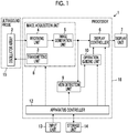
- FIG. 1 A configuration of an ultrasound diagnostic apparatus 1 according to Embodiment 1 of the present invention is shown in Fig. 1 .
- the ultrasound diagnostic apparatus 1 comprises an oscillator array 2, and a transmitting unit 3 and a receiving unit 4 are connected to the oscillator array 2.
- An image generation unit 5, a display controller 6, and a display unit 7 are sequentially connected to the receiving unit 4.
- An image acquisition unit 8 is configured by the transmitting unit 3, the receiving unit 4, and the image generation unit 5.
- a vein detection unit 9 is connected to the image generation unit 5, and an operation guiding unit 10 is connected to the vein detection unit 9.
- the operation guiding unit 10 is connected to the display controller 6.
- the apparatus controller 12 is connected to the display controller 6, the image acquisition unit 8, the vein detection unit 9, the operation guiding unit 10, and the input unit 13 and the storage unit 14 are connected to the apparatus controller 12.
- the apparatus controller 12 and the storage unit 14 are connected to each other so as to be capable of transferring information bidirectionally.
- the oscillator array 2 is included in the ultrasound probe 15, and a processor 16 is configured by the display controller 6, the image acquisition unit 8, the vein detection unit 9, the operation guiding unit 10, and the apparatus controller 12.
- the oscillator array 2 of the ultrasound probe 15 shown in Fig. 1 has a plurality of oscillators arranged in one dimension or two dimensions. These oscillators transmit ultrasound waves in accordance with drive signals supplied from the transmitting unit 3, respectively, and receive ultrasound echoes from the subject to output the received signals.
- the respective oscillators are configured by, for example, forming electrodes to both ends of piezoelectric material made of a piezoelectric ceramic represented by lead zirconate titanate (PZT), a polymeric piezoelectric element represented by polyvinylidene difluoride (PVDF), and a piezoelectric single crystal represented by a lead magnesium niobate-lead titanate solid solution (PMN-PT).
- PZT lead zirconate titanate
- PVDF polymeric piezoelectric element
- PMN-PT piezoelectric single crystal represented by a lead magnesium niobate-lead titanate solid solution
- the transmitting unit 3 of the image acquisition unit 8 includes, for example, a plurality of pulse generators, and adjusts the amounts of delay of the respective drive signals to supply the adjusted drive signals to the plurality of oscillators such that the ultrasound waves transmitted from the plurality of oscillators of the oscillator array 2 form an ultrasound beam, based on a transmission delay pattern selected in accordance with the control signals from the apparatus controller 12.
- a pulsed or consecutive wave-like voltage is applied to electrodes of the plurality of oscillators of the oscillator array 2
- the piezoelectric material expands and contracts
- a pulsed or consecutive wave-like ultrasound wave is generated from the respective oscillators
- the ultrasound beam is formed from a synthetic wave of the ultrasound waves.
- the transmitted ultrasound beam is reflected in, for example, targets such as a part of the subject and is propagated toward the oscillator array 2 of the ultrasound probe 15.
- the ultrasound echoes propagated toward the oscillator array 2 in this way are received by the respective oscillators that constitute the oscillator array 2.
- the respective oscillators that constitute the oscillator array 2 expand and contract by receiving the propagated ultrasound echoes, to generate electrical signals, and output the electrical signals to the receiving unit 4.
- the receiving unit 4 of the image acquisition unit 8 processes the received signals output from the oscillator array 2 in accordance with the control signals from the apparatus controller 12. As shown in Fig. 2 , the receiving unit 4 has a configuration that an amplification unit 17 and an analog-digital (AD) conversion unit 18 are serially connected.
- the amplification unit 17 amplifies the received signals input from the respective oscillators that constitute the oscillator array 2, and transmits the amplified received signals to the AD conversion unit 18.
- the AD conversion unit 18 converts the received signals transmitted from the amplification unit 17 into digitalized data, and sends the data to the image generation unit 5 of the image acquisition unit 8.
- the image generation unit 5 of the image acquisition unit 8 has a configuration that a signal processing unit 19, a digital scan converter (DSC) 20, and an image processing unit 21 are serially connected.
- the signal processing unit 19 performs reception focus processing that addition (phasing addition) is performed by giving each delay to each data of the received signals, based on a reception delay pattern selected in accordance with the control signals from the apparatus controller 12. With the reception focus processing, sound ray signals in which focal points of the ultrasound echoes are narrowed to one scan line are generated.
- the signal processing unit 19 subjects the generated sound ray signals to the correction of damping resulting from a propagation distance depending on the depth at a position where the ultrasound waves are reflected, and then performs envelope detection processing to generate B-mode image signals indicating a tissue in the subject.
- the B-mode image signals generated in this way are output to the DSC 20.
- the DSC 20 of the image generation unit 5 raster-converts the B-mode image signals into image signals based on a scan mode of normal television signals to generate the ultrasound image.
- the image processing unit 21 of the image generation unit 5 subjects the image data obtained in the DSC 20 to various kinds of required image processing such as brightness correction, grayscale correction, sharpness correction, and color correction, and then outputs an ultrasound image to the display controller 6, and the vein detection unit 9.
- the vein detection unit 9 of the processor 16 performs image analysis with respect to the ultrasound image acquired by the image acquisition unit 8, detects the popliteal vein, and calculates the number of the detected popliteal veins.
- the vein detection unit 9 detects the popliteal vein by, for example, recognizing the cross section of the popliteal vein included in the ultrasound image.
- the cross section of the popliteal vein represents the section of the popliteal vein in a case of cutting the popliteal vein across a central axis of the popliteal vein.
- the vein detection unit 9 can recognize the cross section of the popliteal vein by storing typical pattern data as a template in advance, calculating the similarity to the pattern data while searching the image with the template, and assuming the popliteal vein is present in the position where the similarity is equal to or larger than a threshold value and is maximum.
- the artery existing around the popliteal vein may be included in the ultrasound image, but the vein detection unit 9 can recognize the popliteal vein by pattern recognition using the template based on the typical positional relationship between the popliteal vein and the artery, a relative value of typical diameter of the popliteal vein with respect to the typical diameter of the artery.
- the vein detection unit 9 can recognize the popliteal vein by using a so-called Doppler signal as an auxiliary in addition to pattern recognition.
- Example of a general image recognition method using deep learning includes image classification by a convolutional neural network (CNN) in which an ultrasound image including a popliteal vein is positive and an ultrasound image not including a popliteal vein is negative, a semantic segmentation of vein region and artery region using a neural network comprising an up-sampling layer such as U-Net, and vein detection using a bounding box detection model such as Mask-R-CNN
- CNN convolutional neural network
- the DVT that is a disease in which a thrombus occurs in a deep vein
- the DVT often occurs in a lower thigh.
- a normal deep vein in which the thrombus does not occur is easily deformed by compression
- the deep vein in which the thrombus occurs is not easily deformed due to the compression. Therefore, as a test for the DVT, for example, a so-called compression test for observing a cross section of the compressed deep vein while compressing the deep vein having a concern that the DVT may occur is performed.
- a so-called two-point compression method is known in which a compression test is performed with respect to at least only two points of the popliteal vein and the common femoral vein.
- the popliteal vein is generally observed as one blood vessel in a case where the ultrasound probe is brought into contact with the back of the knee of the subject, but in some cases, the vein branches to an upper side of the back of the knee depending on the subject, and a plurality of small blood vessels are observed in a case where the ultrasound probe is brought into contact with the back of the knee of the subject.
- the larger thrombus is likely to occur as the vein is thicker, and in a case where the thrombus is peeled off from the inner wall of the vein and flows to the central side of the vein, pulmonary embolism is likely to be caused, and thus it is desirable that the compression test is performed above the branched part of the vein, that is, at a position in which only one popliteal vein is observed.
- the operation guiding unit 10 of the processor 16 guides the user to operate the ultrasound probe 15 depending on the number of popliteal veins detected by the vein detection unit 9 such that the ultrasound probe 15 is positioned at the position in which only one popliteal vein is included in the ultrasound image acquired by the image generation unit 5.
- the operation guiding unit 10 guides the user to fix the position of the ultrasound probe 15, and in a case where two popliteal veins are detected by the vein detection unit 9, guides the user to move the ultrasound probe 15 to an upper side of the back of the knee of the subject.
- the popliteal vein branches to an upper side of the back of the knee, it prevents the user from performing the compression test on the back of the knee.
- the operation guiding unit 10 can guide the user to operate the ultrasound probe 15 by, for example, displaying the text and the image indicating the guidance for the user on the display unit 7.
- a voice generation unit that generates voice can also be provided in the ultrasound diagnostic apparatus 1, and the operation guiding unit 10 can also guide the user by the voice via the voice generation unit.
- the apparatus controller 12 of the processor 16 performs control of the respective units of the ultrasound diagnostic apparatus 1 based on the programs that are stored in advance in the storage unit 14 and the like and the operation of the user via the input unit 13.
- the display controller 6 of the processor 16 performs predetermined processing on an ultrasound image generated by the image generation unit 5 of the image acquisition unit 8, and displays the ultrasound image on the display unit 7.
- the display unit 7 of the ultrasound diagnostic apparatus 1 displays the ultrasound image under the control of the display controller 6, and includes display devices such as a liquid crystal display (LCD), and an organic electroluminescence (EL) display.
- display devices such as a liquid crystal display (LCD), and an organic electroluminescence (EL) display.
- the input unit 13 of the ultrasound diagnostic apparatus 1 is a device for the user to perform input operation, and can be configured to comprise a keyboard, a mouse, a trackball, a touchpad, a touch panel, and the like.
- the storage unit 14 stores operating programs and the like of the ultrasound diagnostic apparatus 1, and as the storage unit 14, a recording medium such as a hard disc drive (HDD), a solid state drive (SSD), a flexible disc (FD), a magneto-optical (MO) disc, a magnetic tape (MT), a random access memory (RAM), a compact disc (CD), a digital versatile disc (DVD), a secure digital (SD) card, a universal serial bus (USB) memory, or the like, or a server can be used.
- a recording medium such as a hard disc drive (HDD), a solid state drive (SSD), a flexible disc (FD), a magneto-optical (MO) disc, a magnetic tape (MT), a random access memory (RAM), a compact disc (CD), a digital versatile disc (DVD), a secure digital (SD) card, a universal serial bus (USB) memory, or the like, or a server can be used.
- the processor 16 having the display controller 6, the image acquisition unit 8, the vein detection unit 9, the operation guiding unit 10, and the apparatus controller 12 is configured from a central processing unit (CPU) and control programs for making the CPU perform various kinds of processing.
- the processor 16 may be configured from a field programmable gate array (FPGA), a digital signal processor (DSP), an application specific integrated circuit (ASIC), or other integrated circuits (ICs), or may be configured by combining them.
- FPGA field programmable gate array
- DSP digital signal processor
- ASIC application specific integrated circuit
- ICs integrated circuits
- the display controller 6, the image acquisition unit 8, the vein detection unit 9, the operation guiding unit 10, and the apparatus controller 12 of the processor 16 can be partially or wholly integrated into one CPU.
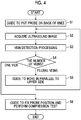
- the flowchart shown in Fig. 4 shows the operation of the ultrasound diagnostic apparatus 1 in a case where the compression test is performed with respect to the popliteal vein of the subject.
- step S1 the operation guiding unit 10 guides the user to position the ultrasound probe 15 on the back of the knee of the subject.
- the operation guiding unit 10 can display, for example, text indicating that the ultrasound probe 15 is positioned at the back of the knee of the subject on the display unit 7. In this way, in a case where the operation guiding unit 10 provides the guidance to the user, the user operates the ultrasound probe 15 to position the ultrasound probe on the back of the knee of the subject.
- step S2 the ultrasound beam is transmitted toward the back of the knee of the subject from the oscillator array 2 of the ultrasound probe 15, and the received signals are generated by the oscillator array 2 based on ultrasound echoes propagated toward the oscillator array 2 from the back of the knee of the subject.
- the received signals generated in this way are sequentially processed by the receiving unit 4 and the image generation unit 5 of the image acquisition unit 8, the ultrasound image representing the cross section of the back of the knee of the subject is acquired.
- the vein detection unit 9 detects the popliteal vein included in the ultrasound image by performing image processing with respect to the ultrasound image acquired in step S2 and calculates the number of the detected popliteal veins.
- the vein detection unit 9 can detect the vein by recognizing the cross section of the blood vessel included in the ultrasound image, and determining whether the recognized blood vessel is the vein or the artery based on the diameter of the recognized blood vessel, the thickness of the vascular wall, and the circularity of the cross section of the blood vessel.
- the operation guiding unit 10 determines that the number of the popliteal veins detected in step S3 is one or plural by receiving the information indicating the number of popliteal veins detected in step S3 from the vein detection unit 9. Based on the determination on whether the popliteal vein detected in step S3 is one or plural, the operation guiding unit 10 guides the user to operate the ultrasound probe 15 such that only one popliteal vein is included in the ultrasound image acquired in step S2 and the ultrasound probe 15 is positioned at the position in which the compression test of the popliteal vein is performed.
- step S4 in a case where the determination is made that the number of popliteal veins detected in step S3 is plural, the process proceeds to step S5.
- step S5 the operation guiding unit 10 guides the user to move the ultrasound probe 15 in parallel to an upper side of the back of the knee of the subject.
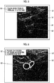
- the operation guiding unit 10 can guide the user to operate the ultrasound probe 15 by, for example, displaying a guide panel G1 including the text indicating the guidance for the user on the display unit 7.
- the guide panel G1 including the text "please move probe in parallel upward” is displayed while being superimposed on an ultrasound image U1 including two of popliteal vein V1 and popliteal vein V2, and one artery A1.
- the user moves the ultrasound probe 15 in parallel to an upper side of the back of the knee of the subject.
- the popliteal vein branches to an upper side of the back of the knee it prevents the user from performing the compression test on the back of the knee.
- the process returns to step S2, and the image acquisition unit 8 acquires a new ultrasound image.
- step S3 the vein detection unit 9 detects the popliteal vein included in the ultrasound image newly acquired in step S2 and calculates the number of the detected popliteal veins.
- step S4 the operation guiding unit 10 determines whether the number of popliteal veins detected in step S3 is only one or plural, and provides different guidance to the user depending on the determination on whether the number of popliteal veins is only one or plural.
- step S4 the process proceeds to step S5, and the operation guiding unit 10 provides the guidance for moving the ultrasound probe 15 in parallel to an upper side of the back of the knee. In this way, the processing items of step S2 to step S5 are repeated until the determination is made that the number of popliteal veins is only one in step S4.
- step S6 the operation guiding unit 10 guides the user to fix the ultrasound probe 15 at the position and perform the compression test.
- the operation guiding unit 10 can guide the user to operate the ultrasound probe 15 by, for example, displaying a guide panel G2 including the text indicating the guidance for the user on the display unit 7.
- the guide panel G2 including the text "please fix position of probe and perform compression test" is displayed while being superimposed on an ultrasound image U2 including only one cross section of the popliteal vein V3 and only one cross section of the artery A2.
- the user fixes the position of the ultrasound probe 15 and performs the compression test.
- the operation of the ultrasound diagnostic apparatus 1 in a case where the compression test is performed with respect to the popliteal vein of the subject ends.
- the ultrasound diagnostic apparatus 1 in a case where the popliteal vein included in the ultrasound image is detected, in particular, a plurality of popliteal veins are detected, the operation of the ultrasound probe 15 is guided for the user such that the ultrasound probe 15 is positioned at an appropriate position regarding the compression test of the popliteal vein, and thus it is possible to perform the compression test at an appropriate position regardless of the skill of the user.
- the transmitting unit 3 and the receiving unit 4 of the image acquisition unit 8 is included in the processor 16, but the transmitting unit and the receiving unit can also be included in the ultrasound probe 15 instead of being included in the processor 16.
- the vein detection unit 9 detects the popliteal vein by using a method such as pattern recognition in a case of detecting the popliteal vein included in the ultrasound image, but the detection accuracy of the popliteal vein can be improved by using a method of discriminating between the artery and the vein as an auxiliary.
- the vein detection unit 9 can discriminate between the vein and the artery by performing the image analysis on the ultrasound image.
- the vascular wall of the vein is thinner than the vascular wall of the artery, the internal pressure of the vein is lower than the internal pressure of the artery, and the circularity of the cross section of the vein is lower than the circularity of the cross section of the artery, and thus the vein detection unit 9 can discriminate between the vein and the artery based on, for example, the diameter of the cross section of the blood vessel, the thickness of the vascular wall, and the circularity of the cross section of the blood vessel included in the ultrasound image.
- the vein detection unit 9 can recognize the vein and the artery included in the ultrasound image by reflecting a difference between the diameters of the cross sections of the vein and the artery, a difference between the thicknesses of the vascular walls, and a difference between the circularities of the cross sections on the template or the feature amount vector in the machine learning method.
- the vein detection unit 9 can classify the vein and the artery, by deep learning such as U-Net, by using the difference between the diameters of the cross sections of vein and the artery, the difference between the thicknesses of the vascular walls, and the circularities between the cross sections.
- the vein and the artery can be discriminated by acquiring the movement of the vascular wall accompanying the beating by a so-called Doppler signal.
- a Doppler processing unit that generates a so-called Doppler signal by analyzing the frequency of the data generated by the receiving unit 4 can be provided in the ultrasound diagnostic apparatus 1, and the vein detection unit 9 can determine that the blood vessel in which the signal intensity of the Doppler signal obtained by the Doppler processing unit changes periodically is the artery, and the blood vessel in which the signal intensity of the Doppler signal changes less is the vein.
- the vein detection unit 9 can discriminate between the vein and the artery by optionally combining a plurality of discriminating methods.
- the vein detection unit 9 can detect the popliteal vein by learning a plurality of discriminating methods by a general image recognition method such as deep learning. More specifically, the vein detection unit 9 can classify or detect the vein and the artery by deep learning by using the Doppler image based on the Doppler signal.
- the vein detection unit 9 can determine the vein and the artery by using the ultrasound image of a plurality of frames by calculating the change rates of the diameter and the area of the blood vessel for each region classified as the blood vessel.
- the processing items of step S2 to step S5 are repeated until the determination is made that the number of popliteal veins included in the ultrasound image is only one in step S4.
- the vein detection processing items of step S3 by tracking the position of the popliteal vein in the ultrasound images sequentially acquired by the image acquisition unit 8 and detecting a bifurcation point in which a plurality of popliteal veins merge into one popliteal vein, the information indicating whether the number of popliteal veins included in the ultrasound image is only one can be obtained.
- the ultrasound diagnostic apparatus 1 can be provided with a bifurcation point detection unit that tracks the position of the popliteal vein included in the ultrasound image by performing the pattern matching between adjacent frames with respect to the ultrasound images sequentially acquired by the image acquisition unit 8 and detects the bifurcation point in which a plurality of popliteal veins merge into one popliteal vein. Accordingly, it is not necessary to perform the vein detection processing every time a new ultrasound image is acquired, and thus the calculation load of the ultrasound diagnostic apparatus 1 can be reduced.
- the ultrasound diagnostic apparatus 1 can be provided with a three-dimensional data generating unit that generates three-dimensional data representing a three-dimensional structure of the popliteal vein based on the result of the vein detection processing performed on the ultrasound images sequentially acquired by the image acquisition unit 8.
- the operation guiding unit 10 can guide the user to position the ultrasound probe 15 at an appropriate position for the compression test of the popliteal vein based on the three-dimensional data generated by the three-dimensional data generating unit.
- the compression test on the common femoral vein is performed in addition to the compression test on the popliteal vein of the subject, and thus, for example, the operation guiding unit 10 can guide the user to position the ultrasound probe 15 on the back of the knee and in the inguinal region of the subject.
- the ultrasound diagnostic apparatus 1 can be provided with a probe position determination unit that recognizes the part of the subject included in the ultrasound image acquired by the image acquisition unit 8 and discriminates whether the ultrasound probe 15 is positioned at the back of the knee or the inguinal region, and the operation guiding unit 10 can guide the user to position the ultrasound probe 15 on the back of the knee and the inguinal region based on the determination result by the probe position determination unit.
- the ultrasound diagnostic apparatus 1 can be provided with a hardness detection unit that generates a so-called elastography image and detects the hardness of the part included in the ultrasound image from the generated elastography image, and the probe position determination unit can determine whether the ultrasound probe 15 is positioned at the back of the knee or in the inguinal region based on the hardness of the part detected by the hardness detection unit.
- Embodiment 1 in a case where a plurality of popliteal veins are detected by the vein detection unit 9, until only one popliteal vein is detected, the ultrasound image is acquired while moving the ultrasound probe 15 to an upper side of the back of the knee, but the movement range of the ultrasound probe 15 can be determined such that the ultrasound probe 15 does not move too much upward.
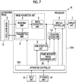
- the configuration of an ultrasound diagnostic apparatus 1A according to Embodiment 2 is shown in Fig. 7 .
- the ultrasound diagnostic apparatus 1A of Embodiment 2 comprises an apparatus controller 12A instead of the apparatus controller 12 in the ultrasound diagnostic apparatus 1 of Embodiment 1 shown in Fig. 1 , and further comprises a probe movement range determining unit 22.
- the probe movement range determining unit 22 is connected to the operation guiding unit 10.
- the apparatus controller 12A is connected to the display controller 6, the image acquisition unit 8, the vein detection unit 9, the operation guiding unit 10, and the input unit 13, the storage unit 14, and the probe movement range determining unit 22.
- a processor 16A is configured by the display controller 6, the image acquisition unit 8, the vein detection unit 9, the operation guiding unit 10, the probe movement range determining unit 22, and the apparatus controller 12A.
- the probe movement range determining unit 22 of the processor 16A determines whether the movement range of the ultrasound probe 15 by the user from a point in time when the vein detection unit 9 detects a plurality of popliteal veins and the operation guiding unit 10 provides the guidance for moving the ultrasound probe 15 to an upper side of the back of the knee of the subject is within a predetermined range.
- the probe movement range determining unit 22 can determine that the movement range of the ultrasound probe 15 is beyond the predetermined range in a case where the ultrasound images more than a predetermined number of frames are acquired by the image acquisition unit 8 or in a case where a predetermined time has elapsed, from a point in time when the operation guiding unit 10 provides the guidance for moving the ultrasound probe 15 to an upper side of the back of the knee.
- the predetermined number of frames representing a predetermined movement range of the ultrasound probe 15 and a predetermined time can be stored in the probe movement range determining unit 22 and the storage unit 14 in advance.
- the flowchart shows an operation of the ultrasound diagnostic apparatus 1A in a case of performing the compression test on the back of the knee, and step S7 and step S8 are added to the flowchart of Embodiment 1 shown in Fig. 4 .
- step S1 the operation guiding unit 10 guides the user to position the ultrasound probe 15 on the back of the knee of the subject.
- the operation guiding unit 10 can display the guide panel G1 including the text indicating the guidance for the user on the display unit 7.
- the user positions the ultrasound probe 15 on the back of the knee of the subject in accordance with the guidance from the operation guiding unit 10.
- step S2 in a case where the image acquisition unit 8 acquires the ultrasound image, the process proceeds to step S3, the vein detection unit 9 detects the popliteal vein included in the acquired ultrasound image and calculates the number of the detected popliteal veins.
- step S4 the operation guiding unit 10 determines whether the number of the popliteal veins detected in step S3 is only one or plural. In a case where the determination is made that the number of popliteal veins is plural in step S4, the process proceeds to step S5, and the operation guiding unit 10 provides the guidance for moving the ultrasound probe 15 in parallel to an upper side of the back of the knee. As a result, the user moves the ultrasound probe 15 in parallel to an upper side of the back of the knee.
- the probe movement range determining unit 22 determines whether the movement range of the ultrasound probe 15 moved by the user is within a predetermined range. In this case, the probe movement range determining unit 22 can determine that the movement range of the ultrasound probe 15 is beyond the predetermined range in a case where the ultrasound images more than a predetermined number of frames are acquired by the image acquisition unit 8 or in a case where a predetermined time has elapsed, from a point in time when the operation guiding unit 10 provides the guidance for moving the ultrasound probe 15 to an upper side of the back of the knee.
- step S7 the process returns to step S2.
- step S2 the image acquisition unit 8 newly acquires the ultrasound image, and in step S3, the popliteal vein included in the newly acquired ultrasound image is detected.
- step S4 determination is made whether the number of the popliteal veins detected in step S3 is only one or plural. In a case where the determination is made that the number of the detected popliteal veins is plural in step S4, the process proceeds to step S5, and the operation guiding unit 10 provides the guidance for moving the ultrasound probe 15 in parallel to an upper side of the back of the knee.
- step S7 the probe movement range determining unit 22 determines whether the movement range of the ultrasound probe 15 moved by the user is within a predetermined range.
- step S7 In a case where the determination is made that the movement range of the ultrasound probe 15 is within a predetermined range in step S7, the process returns to step S2. As described above, the processing items of step S2 to step S5, and step S7 are repeated in a state where the determination is made that the number of the detected popliteal veins is plural in step S4 and until the determination is made that the movement range of the ultrasound probe 15 is beyond a predetermined range in step S7.
- step S8 the operation guiding unit 10 guides the user to return the position of the ultrasound probe 15 to the back of the knee. As a result, the user positions the ultrasound probe 15 on the back of the knee.
- step S8 the process proceeds to step S6, and the operation guiding unit 10 guides the user to fix the position of the ultrasound probe 15 to the position and perform the compression test of the popliteal vein.
- the operation guiding unit 10 can display the guide panel G2 including the text indicating the guidance for the user on the display unit 7. As a result, the operation of the ultrasound diagnostic apparatus 1A ends.
- step S4 the process proceeds to step S6, the operation guiding unit 10 guides the user to fix the position of the ultrasound probe 15 to the position and perform the compression test of the popliteal vein, and then the operation of the ultrasound diagnostic apparatus 1A ends.
- the operation guiding unit 10 provides the guidance for moving the ultrasound probe 15 in parallel to an upper side of the back of the knee, and in a case where the probe movement range determining unit 22 determines that the movement range of the ultrasound probe 15 is beyond a predetermined range, the operation guiding unit 10 provides the guidance for positioning the ultrasound probe 15 on the back of the knee, and thus in a case where a plurality of popliteal veins are detected by the vein detection unit 9 and the user moves the ultrasound probe 15 to an upper side of the back of the knee, it is possible to prevent the ultrasound probe 15 from moving to the position that is not suitable for performing the compression test of the popliteal vein.
- the probe movement range determining unit 22 determines that the movement distance of the ultrasound probe 15 is beyond the predetermined range in a case where the ultrasound images more than a predetermined number of frames is acquired by the image acquisition unit 8 or in a case where a predetermined time has elapsed, from a point in time when the operation guiding unit 10 provides the guidance for moving the ultrasound probe 15 in parallel to an upper side of the back of the knee of the subject, but the determination by the probe movement range determining unit 22 is not limited thereto.
- the probe movement range determining unit 22 can determine whether the movement range of the ultrasound probe 15 is within a predetermined range based on the movement distance of the ultrasound probe 15 estimated directly.
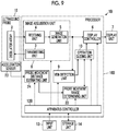
- the configuration of an ultrasound diagnostic apparatus 1B according to a modification example of Embodiment 2 is shown in Fig. 9 .
- the ultrasound diagnostic apparatus 1B comprises an apparatus controller 12B instead of the apparatus controller 12A in the ultrasound diagnostic apparatus 1A of Embodiment 2 shown in Fig. 7 , and further comprises an acceleration sensor 23 and a probe movement distance estimating unit 24.
- the acceleration sensor 23 is attached to the ultrasound probe 15, and the probe movement distance estimating unit 24 is connected to the acceleration sensor 23.
- the probe movement range determining unit 22 is connected to the probe movement distance estimating unit 24.
- the apparatus controller 12B is connected to the display controller 6, the image acquisition unit 8, the vein detection unit 9, the operation guiding unit 10, the input unit 13, the storage unit 14, the probe movement range determining unit 22, and the probe movement distance estimating unit 24.
- a processor 16B is configured by the display controller 6, the image acquisition unit 8, the vein detection unit 9, the operation guiding unit 10, the apparatus controller 12B, the probe movement range determining unit 22, and the probe movement distance estimating unit 24.
- the acceleration sensor 23 attached to the ultrasound probe 15 detects the acceleration of the ultrasound probe 15 moved by the user.
- the probe movement distance estimating unit 24 of the processor 16B estimates the movement distance of the ultrasound probe 15 based on the acceleration of the ultrasound probe 15 detected by the acceleration sensor 23.
- the probe movement range determining unit 22 determines whether the movement distance of the ultrasound probe 15 from a point in time when the operation guiding unit 10 provides the guidance for moving the ultrasound probe 15 in parallel to an upper side of the back of the knee is within a predetermined distance, based on the movement distance of the ultrasound probe 15 estimated by the probe movement distance estimating unit 24. As a result, the probe movement range determining unit 22 can accurately determine whether the movement range of the ultrasound probe 15 is within a predetermined range.
- the ultrasound diagnostic apparatus according to the following supplementary notes 1 to 7 can be grasped.
- An ultrasound diagnostic apparatus that performs a compression test with respect to at least two points of a popliteal vein and a common femoral vein of a subject, the apparatus comprising an ultrasound probe, and a processor, wherein the processor is configured to acquire an ultrasound image by transmitting an ultrasound beam toward the subject from the ultrasound probe, detect the popliteal vein included in the acquired ultrasound image, and in a case where the compression test of the popliteal vein is performed, guide a user to operate the ultrasound probe such that the ultrasound probe is positioned at a position in which only one popliteal vein is included in the acquired ultrasound image based on the number of the detected popliteal veins.
- the ultrasound diagnostic apparatus according to supplementary note 1, wherein the processor is further configured to guide the user to operate the ultrasound probe to fix the position of the ultrasound probe in a case where only one popliteal vein is detected, and guide the user to move the ultrasound probe to an upper side of a back of a knee of the subject in a case where a plurality of popliteal veins are detected.
- the ultrasound diagnostic apparatus according to supplementary note 1 or 2, wherein the processor is further configure to determine whether a movement range of the ultrasound probe by the user from a point in time when the ultrasound probe is guided to be moved to an upper side of a back of a knee of the subject is within a predetermined range, and guide the user to move the ultrasound probe to the back of the knee of the subject in a case where the determination is made that the movement range of the ultrasound probe is beyond the predetermined movement range.
- the ultrasound diagnostic apparatus according to supplementary note 3, wherein the processor is further configured to determine that the movement range of the ultrasound probe is beyond the predetermined movement range in a case where the number of frames of a plurality of the acquired ultrasound images exceeds a predetermined number of frames from a point in time when the operation of the ultrasound probe is guided such that the ultrasound probe is moved to an upper side of the back of the knee.
- the ultrasound diagnostic apparatus according to supplementary note 3, wherein the processor is further configured to determine that the movement range of the ultrasound probe is beyond the predetermined movement range in a case where an elapsed time from a point in time when the operation of the ultrasound probe is guided such that the ultrasound probe is moved to an upper side of the back of the knee exceeds a predetermined time.
- the ultrasound diagnostic apparatus includes an acceleration sensor
- the processor is further configured to estimate a movement distance of the ultrasound probe based on an acceleration of the ultrasound probe measured by the acceleration sensor, and determine that the movement range of the ultrasound probe from a point in time when the operation of the ultrasound probe is guided such that the ultrasound probe is moved to an upper side of the back of the knee is beyond the predetermined movement range in a case where the estimated movement distance of the ultrasound probe exceeds a predetermined distance.
- the ultrasound diagnostic apparatus according to any one of supplementary notes 1 to 6, further comprising a display device, wherein the processor is further configured to cause the display device to display operation guidance on the ultrasound probe for the user.
Landscapes
- Health & Medical Sciences (AREA)
- Life Sciences & Earth Sciences (AREA)
- Biomedical Technology (AREA)
- Biophysics (AREA)
- Nuclear Medicine, Radiotherapy & Molecular Imaging (AREA)
- Pathology (AREA)
- Radiology & Medical Imaging (AREA)
- Engineering & Computer Science (AREA)
- Physics & Mathematics (AREA)
- Heart & Thoracic Surgery (AREA)
- Medical Informatics (AREA)
- Molecular Biology (AREA)
- Surgery (AREA)
- Animal Behavior & Ethology (AREA)
- General Health & Medical Sciences (AREA)
- Public Health (AREA)
- Veterinary Medicine (AREA)
- Vascular Medicine (AREA)
- Ultra Sonic Daignosis Equipment (AREA)
Abstract
Description
- The present invention relates to an ultrasound diagnostic apparatus and a method of controlling an ultrasound diagnostic apparatus, and particularly, to an ultrasound diagnostic apparatus and a method of controlling an ultrasound diagnostic apparatus that are used for a compression test of a popliteal vein of a subject.
- In the related art, an ultrasound diagnostic apparatus has been known as an apparatus that obtains an image of the inside of a subject. Generally, the ultrasound diagnostic apparatus comprises an ultrasound probe provided with an oscillator array in which a plurality of elements are arranged. In a state where the ultrasound probe is brought into contact with a body surface of the subject, an ultrasound beam is transmitted from the oscillator array toward the inside of the subject, ultrasound echoes from the subject are received by the oscillator array, and element data are acquired. Moreover, the ultrasound diagnostic apparatus processes the obtained element data electrically, and generates an ultrasound image for a relevant part of the subj ect.
- It is generally performed that a blood vessel of the subject is observed using such an ultrasound diagnostic apparatus, and the presence or absence of a thrombus in the blood vessel is inspected. As a disease related to the thrombus in the blood vessel, for example, a so-called deep vein thrombosis (DVT) is known. The DVT is a disease that a thrombus occurs in a deep vein, and often occurs in a lower thigh.
- Although a normal deep vein in which the thrombus is not present is easily deformed by compression, the deep vein in which the thrombus occurs is not easily deformed by the compression. Therefore, as a method of inspecting the DVT that occurs in the lower thigh using the ultrasound diagnostic apparatus, for example, so-called compression test method of observing a cross section of the compressed deep vein while compressing the deep vein having a concern that the DVT may occur is known.
- For the ultrasound diagnostic apparatus, various measures are made in order to accurately perform such a compression test. For example,
JP2008-272025A - As a method of quickly detecting DVT occurring in the lower thigh of the subject, a so-called two-point compression method is known in which a compression test is performed with respect to only two points of the popliteal vein and the common femoral vein. The popliteal vein is generally observed as one blood vessel in a case where the ultrasound probe is brought into contact with the back of the knee of the subject, but in some cases, the popliteal vein branches to an upper side of the back of the knee depending on the subject, and two small blood vessels are observed in a case where the ultrasound probe is brought into contact with the back of the knee of the subject.
- In general, the larger thrombus is likely to occur as the vein is thicker, and in a case where the thrombus is peeled off from the inner wall of the vein and flows to the central side of the vein, pulmonary embolism is likely to be caused, and thus it is desirable that the compression test is performed above the branched part of the vein. However, for example, a less skilled user may perform the compression test without moving the position of the ultrasound probe from the back of the knee, even in a case where the vein branches to an upper side of the back of the knee. In such a case, even with the ultrasound diagnostic apparatus disclosed in
JP2008-272025A - The present invention has been made in order to solve such related-art problems, and an object thereof is to provide an ultrasound diagnostic apparatus and a method of controlling an ultrasound diagnostic apparatus that perform a compression test at an appropriate position regardless of the skill of the user.
- In order to achieve the above object, an ultrasound diagnostic apparatus according to an aspect of the present invention, which performs a compression test with respect to at least two points of a popliteal vein and a common femoral vein of a subject, comprises an ultrasound probe, an image acquisition unit that acquire an ultrasound image by transmitting an ultrasound beam toward the subject from the ultrasound probe, a vein detection unit that detects the popliteal vein included in the ultrasound image acquired by the image acquisition unit, and an operation guiding unit that guides a user, in a case where the compression test of the popliteal vein is performed, to operate the ultrasound probe such that the ultrasound probe is positioned at a position in which only one popliteal vein is included in the ultrasound image acquired by the image acquisition unit based on the number of the popliteal veins detected by the vein detection unit.
- It is preferable that the operation guiding unit guide the user to operate the ultrasound probe to fix the position of the ultrasound probe in a case where only one popliteal vein is detected by the vein detection unit, and guide the user to move the ultrasound probe to an upper side of a back of a knee of the subject in a case where a plurality of the popliteal veins are detected by the vein detection unit.
- It is preferable that the ultrasound diagnostic apparatus further comprise a probe movement range determining unit that determines whether a movement range of the ultrasound probe by the user from a point in time when the ultrasound probe is guided by the operation guiding unit to be moved to an upper side of a back of a knee of the subject is within a predetermined range, in which the operation guiding unit guides the user to move the ultrasound probe to the back of the knee of the subject in a case where the probe movement range determining unit determines that the movement range of the ultrasound probe is beyond the predetermined movement range.
- In this case, the probe movement range determining unit may determine that the movement range of the ultrasound probe is beyond the predetermined movement range in a case where the number of frames of a plurality of the ultrasound images acquired by the image acquisition unit from a point in time when the operation of the ultrasound probe is guided by the operation guiding unit such that the ultrasound probe is moved to an upper side of the back of the knee exceeds a predetermined number of frames.
- Alternatively, the probe movement range determining unit may determine that the movement range of the ultrasound probe is beyond the predetermined movement range in a case where an elapsed time from a point in time when the operation of the ultrasound probe is guided by the operation guiding unit such that the ultrasound probe is moved to an upper side of the back of the knee exceeds a predetermined time.
- Also, the ultrasound probe may include an acceleration sensor, the ultrasound diagnostic apparatus may further comprise a probe movement distance estimating unit that estimates a movement distance of the ultrasound probe based on an acceleration of the ultrasound probe measured by the acceleration sensor, and the probe movement range determining unit may determine that the movement range of the ultrasound probe is beyond the predetermined movement range in a case where the movement distance of the ultrasound probe estimated by the probe movement distance estimating unit from a point in time when the operation of the ultrasound probe is guided by the operation guiding unit such that the ultrasound probe is moved to an upper side of the back of the knee exceeds a predetermined distance.
- The ultrasound diagnostic apparatus may further comprise a display unit, in which the operation guiding unit causes the display unit to display operation guidance on the ultrasound probe for the user.
- A method of controlling an ultrasound diagnostic apparatus that performs a compression test with respect to at least two points of a popliteal vein and a common femoral vein of a subject according to another aspect of the present invention comprises transmitting an ultrasound beam toward a back of a knee of the subject from an ultrasound probe to acquire an ultrasound image, detecting the popliteal vein included in the acquired ultrasound image, and guiding, in a case where the compression test of the popliteal vein is performed, a user to operate the ultrasound probe based on the number of the detected popliteal veins such that the ultrasound probe is positioned at a position in which only one popliteal vein is included in the acquired ultrasound image.
- According to the present invention, an ultrasound diagnostic apparatus comprises a vein detection unit that detects the popliteal vein included in the ultrasound image acquired by the image acquisition unit, and an operation guiding unit that guides a user, in a case where the compression test of the popliteal vein is performed, to operate the ultrasound probe such that the ultrasound probe is positioned at a position in which only one popliteal vein is included in the ultrasound image acquired by the image acquisition unit based on the number of the popliteal veins detected by the vein detection unit, and thus it is possible to perform a compression test at an appropriate position regardless of the skill of the user.
-
-
Fig. 1 is a block diagram showing a configuration of an ultrasound diagnostic apparatus according to Embodiment 1 of the present invention. -
Fig. 2 is a block diagram showing an internal configuration of a receiving unit according to Embodiment 1 of the present invention. -
Fig. 3 is a block diagram showing an internal configuration of an image generation unit according to Embodiment 1 of the present invention. -
Fig. 4 is a flowchart showing an operation of the ultrasound diagnostic apparatus according to Embodiment 1 of the present invention. -
Fig. 5 is a diagram showing an example of operation guidance in Embodiment 1 of the present invention. -
Fig. 6 is a diagram showing another example of operation guidance in Embodiment 1 of the present invention. -
Fig. 7 is a block diagram showing a configuration of an ultrasound diagnostic apparatus according toEmbodiment 2 of the present invention. -
Fig. 8 is a flowchart showing an operation of the ultrasound diagnostic apparatus according toEmbodiment 2 of the present invention. -
Fig. 9 is a block diagram showing a configuration of an ultrasound diagnostic apparatus according to a modification example ofEmbodiment 2 of the present invention. - Hereinafter, embodiments of the present invention will be described based on the accompanying drawings.
- A configuration of an ultrasound diagnostic apparatus 1 according to Embodiment 1 of the present invention is shown in
Fig. 1 . As shown inFig. 1 , the ultrasound diagnostic apparatus 1 comprises anoscillator array 2, and a transmittingunit 3 and areceiving unit 4 are connected to theoscillator array 2. Animage generation unit 5, adisplay controller 6, and adisplay unit 7 are sequentially connected to thereceiving unit 4. Animage acquisition unit 8 is configured by the transmittingunit 3, thereceiving unit 4, and theimage generation unit 5. Avein detection unit 9 is connected to theimage generation unit 5, and anoperation guiding unit 10 is connected to thevein detection unit 9. Theoperation guiding unit 10 is connected to thedisplay controller 6. - The
apparatus controller 12 is connected to thedisplay controller 6, theimage acquisition unit 8, thevein detection unit 9, theoperation guiding unit 10, and theinput unit 13 and thestorage unit 14 are connected to theapparatus controller 12. Theapparatus controller 12 and thestorage unit 14 are connected to each other so as to be capable of transferring information bidirectionally. - The
oscillator array 2 is included in theultrasound probe 15, and aprocessor 16 is configured by thedisplay controller 6, theimage acquisition unit 8, thevein detection unit 9, theoperation guiding unit 10, and theapparatus controller 12. - The
oscillator array 2 of theultrasound probe 15 shown inFig. 1 has a plurality of oscillators arranged in one dimension or two dimensions. These oscillators transmit ultrasound waves in accordance with drive signals supplied from the transmittingunit 3, respectively, and receive ultrasound echoes from the subject to output the received signals. The respective oscillators are configured by, for example, forming electrodes to both ends of piezoelectric material made of a piezoelectric ceramic represented by lead zirconate titanate (PZT), a polymeric piezoelectric element represented by polyvinylidene difluoride (PVDF), and a piezoelectric single crystal represented by a lead magnesium niobate-lead titanate solid solution (PMN-PT). - The transmitting
unit 3 of theimage acquisition unit 8 includes, for example, a plurality of pulse generators, and adjusts the amounts of delay of the respective drive signals to supply the adjusted drive signals to the plurality of oscillators such that the ultrasound waves transmitted from the plurality of oscillators of theoscillator array 2 form an ultrasound beam, based on a transmission delay pattern selected in accordance with the control signals from theapparatus controller 12. In this way, in a case where a pulsed or consecutive wave-like voltage is applied to electrodes of the plurality of oscillators of theoscillator array 2, the piezoelectric material expands and contracts, a pulsed or consecutive wave-like ultrasound wave is generated from the respective oscillators, and the ultrasound beam is formed from a synthetic wave of the ultrasound waves. - The transmitted ultrasound beam is reflected in, for example, targets such as a part of the subject and is propagated toward the
oscillator array 2 of theultrasound probe 15. The ultrasound echoes propagated toward theoscillator array 2 in this way are received by the respective oscillators that constitute theoscillator array 2. In this case, the respective oscillators that constitute theoscillator array 2 expand and contract by receiving the propagated ultrasound echoes, to generate electrical signals, and output the electrical signals to thereceiving unit 4. - The receiving
unit 4 of theimage acquisition unit 8 processes the received signals output from theoscillator array 2 in accordance with the control signals from theapparatus controller 12. As shown inFig. 2 , thereceiving unit 4 has a configuration that anamplification unit 17 and an analog-digital (AD)conversion unit 18 are serially connected. Theamplification unit 17 amplifies the received signals input from the respective oscillators that constitute theoscillator array 2, and transmits the amplified received signals to theAD conversion unit 18. TheAD conversion unit 18 converts the received signals transmitted from theamplification unit 17 into digitalized data, and sends the data to theimage generation unit 5 of theimage acquisition unit 8. - As shown in
Fig. 3 , theimage generation unit 5 of theimage acquisition unit 8 has a configuration that asignal processing unit 19, a digital scan converter (DSC) 20, and animage processing unit 21 are serially connected. Thesignal processing unit 19 performs reception focus processing that addition (phasing addition) is performed by giving each delay to each data of the received signals, based on a reception delay pattern selected in accordance with the control signals from theapparatus controller 12. With the reception focus processing, sound ray signals in which focal points of the ultrasound echoes are narrowed to one scan line are generated. Additionally, thesignal processing unit 19 subjects the generated sound ray signals to the correction of damping resulting from a propagation distance depending on the depth at a position where the ultrasound waves are reflected, and then performs envelope detection processing to generate B-mode image signals indicating a tissue in the subject. The B-mode image signals generated in this way are output to theDSC 20. - The
DSC 20 of theimage generation unit 5 raster-converts the B-mode image signals into image signals based on a scan mode of normal television signals to generate the ultrasound image. Theimage processing unit 21 of theimage generation unit 5 subjects the image data obtained in theDSC 20 to various kinds of required image processing such as brightness correction, grayscale correction, sharpness correction, and color correction, and then outputs an ultrasound image to thedisplay controller 6, and thevein detection unit 9. - The
vein detection unit 9 of theprocessor 16 performs image analysis with respect to the ultrasound image acquired by theimage acquisition unit 8, detects the popliteal vein, and calculates the number of the detected popliteal veins. In this case, thevein detection unit 9 detects the popliteal vein by, for example, recognizing the cross section of the popliteal vein included in the ultrasound image. The cross section of the popliteal vein represents the section of the popliteal vein in a case of cutting the popliteal vein across a central axis of the popliteal vein. More specifically, for example, thevein detection unit 9 can recognize the cross section of the popliteal vein by storing typical pattern data as a template in advance, calculating the similarity to the pattern data while searching the image with the template, and assuming the popliteal vein is present in the position where the similarity is equal to or larger than a threshold value and is maximum. The artery existing around the popliteal vein may be included in the ultrasound image, but thevein detection unit 9 can recognize the popliteal vein by pattern recognition using the template based on the typical positional relationship between the popliteal vein and the artery, a relative value of typical diameter of the popliteal vein with respect to the typical diameter of the artery. Thevein detection unit 9 can recognize the popliteal vein by using a so-called Doppler signal as an auxiliary in addition to pattern recognition. - A machine learning method described in Csurka et al.: Visual Categorization with Bags of Keypoints, Proc. of ECCV Workshop on Statistical Learning in Computer Vision, pp.59-74 (2004), a general image recognition method using deep learning described in Krizhevsky et al.: Image Net Classification with Deep Convolutional Neural Networks, Advances in Neural Information Processing Systems 25, and pp. 1106-1114 (2012), or the like can be used for the calculation of the similarity in addition to the simple template matching. Example of a general image recognition method using deep learning includes image classification by a convolutional neural network (CNN) in which an ultrasound image including a popliteal vein is positive and an ultrasound image not including a popliteal vein is negative, a semantic segmentation of vein region and artery region using a neural network comprising an up-sampling layer such as U-Net, and vein detection using a bounding box detection model such as Mask-R-CNN
- In general, the DVT that is a disease in which a thrombus occurs in a deep vein is known, and the DVT often occurs in a lower thigh. Although a normal deep vein in which the thrombus does not occur is easily deformed by compression, the deep vein in which the thrombus occurs is not easily deformed due to the compression. Therefore, as a test for the DVT, for example, a so-called compression test for observing a cross section of the compressed deep vein while compressing the deep vein having a concern that the DVT may occur is performed. As a method of quickly detecting DVT generated in the lower thigh of the subject, a so-called two-point compression method is known in which a compression test is performed with respect to at least only two points of the popliteal vein and the common femoral vein. The popliteal vein is generally observed as one blood vessel in a case where the ultrasound probe is brought into contact with the back of the knee of the subject, but in some cases, the vein branches to an upper side of the back of the knee depending on the subject, and a plurality of small blood vessels are observed in a case where the ultrasound probe is brought into contact with the back of the knee of the subject. In general, the larger thrombus is likely to occur as the vein is thicker, and in a case where the thrombus is peeled off from the inner wall of the vein and flows to the central side of the vein, pulmonary embolism is likely to be caused, and thus it is desirable that the compression test is performed above the branched part of the vein, that is, at a position in which only one popliteal vein is observed.
- In a case where the compression test of the popliteal vein is performed, the
operation guiding unit 10 of theprocessor 16 guides the user to operate theultrasound probe 15 depending on the number of popliteal veins detected by thevein detection unit 9 such that theultrasound probe 15 is positioned at the position in which only one popliteal vein is included in the ultrasound image acquired by theimage generation unit 5. For example, in a case where theultrasound probe 15 is positioned at the back of the knee of the subject by the user and only one popliteal vein is detected by thevein detection unit 9, theoperation guiding unit 10 guides the user to fix the position of theultrasound probe 15, and in a case where two popliteal veins are detected by thevein detection unit 9, guides the user to move theultrasound probe 15 to an upper side of the back of the knee of the subject. Thus, in a case where the popliteal vein branches to an upper side of the back of the knee, it prevents the user from performing the compression test on the back of the knee. - In this case, the
operation guiding unit 10 can guide the user to operate theultrasound probe 15 by, for example, displaying the text and the image indicating the guidance for the user on thedisplay unit 7. Additionally, although not shown, for example, a voice generation unit that generates voice can also be provided in the ultrasound diagnostic apparatus 1, and theoperation guiding unit 10 can also guide the user by the voice via the voice generation unit. - The
apparatus controller 12 of theprocessor 16 performs control of the respective units of the ultrasound diagnostic apparatus 1 based on the programs that are stored in advance in thestorage unit 14 and the like and the operation of the user via theinput unit 13. - Under the control of the
apparatus controller 12, thedisplay controller 6 of theprocessor 16 performs predetermined processing on an ultrasound image generated by theimage generation unit 5 of theimage acquisition unit 8, and displays the ultrasound image on thedisplay unit 7. - The
display unit 7 of the ultrasound diagnostic apparatus 1 displays the ultrasound image under the control of thedisplay controller 6, and includes display devices such as a liquid crystal display (LCD), and an organic electroluminescence (EL) display. - The
input unit 13 of the ultrasound diagnostic apparatus 1 is a device for the user to perform input operation, and can be configured to comprise a keyboard, a mouse, a trackball, a touchpad, a touch panel, and the like. - The
storage unit 14 stores operating programs and the like of the ultrasound diagnostic apparatus 1, and as thestorage unit 14, a recording medium such as a hard disc drive (HDD), a solid state drive (SSD), a flexible disc (FD), a magneto-optical (MO) disc, a magnetic tape (MT), a random access memory (RAM), a compact disc (CD), a digital versatile disc (DVD), a secure digital (SD) card, a universal serial bus (USB) memory, or the like, or a server can be used. - In addition, the
processor 16 having thedisplay controller 6, theimage acquisition unit 8, thevein detection unit 9, theoperation guiding unit 10, and theapparatus controller 12 is configured from a central processing unit (CPU) and control programs for making the CPU perform various kinds of processing. However, theprocessor 16 may be configured from a field programmable gate array (FPGA), a digital signal processor (DSP), an application specific integrated circuit (ASIC), or other integrated circuits (ICs), or may be configured by combining them. - Also, the
display controller 6, theimage acquisition unit 8, thevein detection unit 9, theoperation guiding unit 10, and theapparatus controller 12 of theprocessor 16 can be partially or wholly integrated into one CPU. - Next, the operation of the ultrasound diagnostic apparatus 1 in Embodiment 1 will be described in detail using a flowchart shown in
Fig. 4 . The flowchart shown inFig. 4 shows the operation of the ultrasound diagnostic apparatus 1 in a case where the compression test is performed with respect to the popliteal vein of the subject. - First, in step S1, the
operation guiding unit 10 guides the user to position theultrasound probe 15 on the back of the knee of the subject. Although not shown, in this case, theoperation guiding unit 10 can display, for example, text indicating that theultrasound probe 15 is positioned at the back of the knee of the subject on thedisplay unit 7. In this way, in a case where theoperation guiding unit 10 provides the guidance to the user, the user operates theultrasound probe 15 to position the ultrasound probe on the back of the knee of the subject. - Next, in step S2, the ultrasound beam is transmitted toward the back of the knee of the subject from the
oscillator array 2 of theultrasound probe 15, and the received signals are generated by theoscillator array 2 based on ultrasound echoes propagated toward theoscillator array 2 from the back of the knee of the subject. As the received signals generated in this way are sequentially processed by the receivingunit 4 and theimage generation unit 5 of theimage acquisition unit 8, the ultrasound image representing the cross section of the back of the knee of the subject is acquired. - In step S3, the
vein detection unit 9 detects the popliteal vein included in the ultrasound image by performing image processing with respect to the ultrasound image acquired in step S2 and calculates the number of the detected popliteal veins. In this case, for example, thevein detection unit 9 can detect the vein by recognizing the cross section of the blood vessel included in the ultrasound image, and determining whether the recognized blood vessel is the vein or the artery based on the diameter of the recognized blood vessel, the thickness of the vascular wall, and the circularity of the cross section of the blood vessel. - In following step S4, the
operation guiding unit 10 determines that the number of the popliteal veins detected in step S3 is one or plural by receiving the information indicating the number of popliteal veins detected in step S3 from thevein detection unit 9. Based on the determination on whether the popliteal vein detected in step S3 is one or plural, theoperation guiding unit 10 guides the user to operate theultrasound probe 15 such that only one popliteal vein is included in the ultrasound image acquired in step S2 and theultrasound probe 15 is positioned at the position in which the compression test of the popliteal vein is performed. - In step S4, in a case where the determination is made that the number of popliteal veins detected in step S3 is plural, the process proceeds to step S5. In step S5, the
operation guiding unit 10 guides the user to move theultrasound probe 15 in parallel to an upper side of the back of the knee of the subject. In this case, as shown inFig. 5 , theoperation guiding unit 10 can guide the user to operate theultrasound probe 15 by, for example, displaying a guide panel G1 including the text indicating the guidance for the user on thedisplay unit 7. In the example ofFig. 5 , the guide panel G1 including the text "please move probe in parallel upward" is displayed while being superimposed on an ultrasound image U1 including two of popliteal vein V1 and popliteal vein V2, and one artery A1. In this way, in a case where the operation of theultrasound probe 15 is guided to the user, the user moves theultrasound probe 15 in parallel to an upper side of the back of the knee of the subject. Thus, in a case where the popliteal vein branches to an upper side of the back of the knee, it prevents the user from performing the compression test on the back of the knee. - In this way, in a state where the
ultrasound probe 15 is moved by the user in parallel to an upper side of the back of the knee, the process returns to step S2, and theimage acquisition unit 8 acquires a new ultrasound image. - In step S3, the
vein detection unit 9 detects the popliteal vein included in the ultrasound image newly acquired in step S2 and calculates the number of the detected popliteal veins. - In following step S4, the
operation guiding unit 10 determines whether the number of popliteal veins detected in step S3 is only one or plural, and provides different guidance to the user depending on the determination on whether the number of popliteal veins is only one or plural. - In a case where the determination is made that the number of popliteal veins is plural in step S4, the process proceeds to step S5, and the
operation guiding unit 10 provides the guidance for moving theultrasound probe 15 in parallel to an upper side of the back of the knee. In this way, the processing items of step S2 to step S5 are repeated until the determination is made that the number of popliteal veins is only one in step S4. - In a case where the determination is made that the number of popliteal veins is one in step S4, the process proceeds to step S6. In step S6, the
operation guiding unit 10 guides the user to fix theultrasound probe 15 at the position and perform the compression test. In this case, as shown inFig. 6 , theoperation guiding unit 10 can guide the user to operate theultrasound probe 15 by, for example, displaying a guide panel G2 including the text indicating the guidance for the user on thedisplay unit 7. In the example ofFig. 6 , the guide panel G2 including the text "please fix position of probe and perform compression test" is displayed while being superimposed on an ultrasound image U2 including only one cross section of the popliteal vein V3 and only one cross section of the artery A2. In this way, in a case where the operation of theultrasound probe 15 is guided to the user, the user fixes the position of theultrasound probe 15 and performs the compression test. As a result, the operation of the ultrasound diagnostic apparatus 1 in a case where the compression test is performed with respect to the popliteal vein of the subject ends. - As described above, in the ultrasound diagnostic apparatus 1 according to Embodiment 1, in a case where the popliteal vein included in the ultrasound image is detected, in particular, a plurality of popliteal veins are detected, the operation of the
ultrasound probe 15 is guided for the user such that theultrasound probe 15 is positioned at an appropriate position regarding the compression test of the popliteal vein, and thus it is possible to perform the compression test at an appropriate position regardless of the skill of the user. - In Embodiment 1, the transmitting
unit 3 and the receivingunit 4 of theimage acquisition unit 8 is included in theprocessor 16, but the transmitting unit and the receiving unit can also be included in theultrasound probe 15 instead of being included in theprocessor 16. - Also, in Embodiment 1, the
vein detection unit 9 detects the popliteal vein by using a method such as pattern recognition in a case of detecting the popliteal vein included in the ultrasound image, but the detection accuracy of the popliteal vein can be improved by using a method of discriminating between the artery and the vein as an auxiliary. - For example, the
vein detection unit 9 can discriminate between the vein and the artery by performing the image analysis on the ultrasound image. In general, the vascular wall of the vein is thinner than the vascular wall of the artery, the internal pressure of the vein is lower than the internal pressure of the artery, and the circularity of the cross section of the vein is lower than the circularity of the cross section of the artery, and thus thevein detection unit 9 can discriminate between the vein and the artery based on, for example, the diameter of the cross section of the blood vessel, the thickness of the vascular wall, and the circularity of the cross section of the blood vessel included in the ultrasound image. For example, thevein detection unit 9 can recognize the vein and the artery included in the ultrasound image by reflecting a difference between the diameters of the cross sections of the vein and the artery, a difference between the thicknesses of the vascular walls, and a difference between the circularities of the cross sections on the template or the feature amount vector in the machine learning method. For example, thevein detection unit 9 can classify the vein and the artery, by deep learning such as U-Net, by using the difference between the diameters of the cross sections of vein and the artery, the difference between the thicknesses of the vascular walls, and the circularities between the cross sections. - The artery beats in response to the heart beat, but the vein does not beat, and thus, for example, the
vein detection unit 9 can discriminate between the vein and the artery by determining whether the blood vessel included in the ultrasound image beats. More specifically, for example, thevein detection unit 9 can calculate the diameter of the blood vessel included in the ultrasound image with respect to the ultrasound images sequentially acquired by theimage acquisition unit 8 in a state where the position of theultrasound probe 15 is fixed, and determine that the blood vessel having periodically changed diameter is the artery, and the blood vessel having not periodically changed diameter is the vein. - In addition, the vein and the artery can be discriminated by acquiring the movement of the vascular wall accompanying the beating by a so-called Doppler signal. More specifically, for example, although not shown, a Doppler processing unit that generates a so-called Doppler signal by analyzing the frequency of the data generated by the receiving
unit 4 can be provided in the ultrasound diagnostic apparatus 1, and thevein detection unit 9 can determine that the blood vessel in which the signal intensity of the Doppler signal obtained by the Doppler processing unit changes periodically is the artery, and the blood vessel in which the signal intensity of the Doppler signal changes less is the vein. - For example, the
vein detection unit 9 can discriminate between the vein and the artery by optionally combining a plurality of discriminating methods. Thevein detection unit 9 can detect the popliteal vein by learning a plurality of discriminating methods by a general image recognition method such as deep learning. More specifically, thevein detection unit 9 can classify or detect the vein and the artery by deep learning by using the Doppler image based on the Doppler signal. Thevein detection unit 9 can determine the vein and the artery by using the ultrasound image of a plurality of frames by calculating the change rates of the diameter and the area of the blood vessel for each region classified as the blood vessel. - In Embodiment 1, the processing items of step S2 to step S5 are repeated until the determination is made that the number of popliteal veins included in the ultrasound image is only one in step S4. In this case, for example, instead of the vein detection processing items of step S3, by tracking the position of the popliteal vein in the ultrasound images sequentially acquired by the
image acquisition unit 8 and detecting a bifurcation point in which a plurality of popliteal veins merge into one popliteal vein, the information indicating whether the number of popliteal veins included in the ultrasound image is only one can be obtained. For example, in order to perform such processing, although not shown, the ultrasound diagnostic apparatus 1 can be provided with a bifurcation point detection unit that tracks the position of the popliteal vein included in the ultrasound image by performing the pattern matching between adjacent frames with respect to the ultrasound images sequentially acquired by theimage acquisition unit 8 and detects the bifurcation point in which a plurality of popliteal veins merge into one popliteal vein. Accordingly, it is not necessary to perform the vein detection processing every time a new ultrasound image is acquired, and thus the calculation load of the ultrasound diagnostic apparatus 1 can be reduced. - In a case where the discrimination is made that a plurality of popliteal veins are included in the ultrasound image in step S4, for example, although not shown, the ultrasound diagnostic apparatus 1 can be provided with a three-dimensional data generating unit that generates three-dimensional data representing a three-dimensional structure of the popliteal vein based on the result of the vein detection processing performed on the ultrasound images sequentially acquired by the
image acquisition unit 8. In this case, theoperation guiding unit 10 can guide the user to position theultrasound probe 15 at an appropriate position for the compression test of the popliteal vein based on the three-dimensional data generated by the three-dimensional data generating unit. - In the DVT test using the two-point compression method, the compression test on the common femoral vein is performed in addition to the compression test on the popliteal vein of the subject, and thus, for example, the
operation guiding unit 10 can guide the user to position theultrasound probe 15 on the back of the knee and in the inguinal region of the subject. In this case, for example, although not shown, the ultrasound diagnostic apparatus 1 can be provided with a probe position determination unit that recognizes the part of the subject included in the ultrasound image acquired by theimage acquisition unit 8 and discriminates whether theultrasound probe 15 is positioned at the back of the knee or the inguinal region, and theoperation guiding unit 10 can guide the user to position theultrasound probe 15 on the back of the knee and the inguinal region based on the determination result by the probe position determination unit. - In general, the hardness of the back of the knee and the hardness of the inguinal region are different, for example, the ultrasound diagnostic apparatus 1 can be provided with a hardness detection unit that generates a so-called elastography image and detects the hardness of the part included in the ultrasound image from the generated elastography image, and the probe position determination unit can determine whether the
ultrasound probe 15 is positioned at the back of the knee or in the inguinal region based on the hardness of the part detected by the hardness detection unit. - In Embodiment 1, in a case where a plurality of popliteal veins are detected by the
vein detection unit 9, until only one popliteal vein is detected, the ultrasound image is acquired while moving theultrasound probe 15 to an upper side of the back of the knee, but the movement range of theultrasound probe 15 can be determined such that theultrasound probe 15 does not move too much upward. - The configuration of an ultrasound
diagnostic apparatus 1A according toEmbodiment 2 is shown inFig. 7 . The ultrasounddiagnostic apparatus 1A ofEmbodiment 2 comprises anapparatus controller 12A instead of theapparatus controller 12 in the ultrasound diagnostic apparatus 1 of Embodiment 1 shown inFig. 1 , and further comprises a probe movementrange determining unit 22. - In the ultrasound
diagnostic apparatus 1A according toEmbodiment 2, the probe movementrange determining unit 22 is connected to theoperation guiding unit 10. Theapparatus controller 12A is connected to thedisplay controller 6, theimage acquisition unit 8, thevein detection unit 9, theoperation guiding unit 10, and theinput unit 13, thestorage unit 14, and the probe movementrange determining unit 22. Aprocessor 16A is configured by thedisplay controller 6, theimage acquisition unit 8, thevein detection unit 9, theoperation guiding unit 10, the probe movementrange determining unit 22, and theapparatus controller 12A. - The probe movement
range determining unit 22 of theprocessor 16A determines whether the movement range of theultrasound probe 15 by the user from a point in time when thevein detection unit 9 detects a plurality of popliteal veins and theoperation guiding unit 10 provides the guidance for moving theultrasound probe 15 to an upper side of the back of the knee of the subject is within a predetermined range. For example, the probe movementrange determining unit 22 can determine that the movement range of theultrasound probe 15 is beyond the predetermined range in a case where the ultrasound images more than a predetermined number of frames are acquired by theimage acquisition unit 8 or in a case where a predetermined time has elapsed, from a point in time when theoperation guiding unit 10 provides the guidance for moving theultrasound probe 15 to an upper side of the back of the knee. - The predetermined number of frames representing a predetermined movement range of the
ultrasound probe 15 and a predetermined time can be stored in the probe movementrange determining unit 22 and thestorage unit 14 in advance. - Next, the operation of the ultrasound
diagnostic apparatus 1A according toEmbodiment 2 will be described using the flowchart shown inFig. 8 . The flowchart shows an operation of the ultrasounddiagnostic apparatus 1A in a case of performing the compression test on the back of the knee, and step S7 and step S8 are added to the flowchart of Embodiment 1 shown inFig. 4 . - First, in step S1, the
operation guiding unit 10 guides the user to position theultrasound probe 15 on the back of the knee of the subject. In this case, as shown inFig. 5 , theoperation guiding unit 10 can display the guide panel G1 including the text indicating the guidance for the user on thedisplay unit 7. The user positions theultrasound probe 15 on the back of the knee of the subject in accordance with the guidance from theoperation guiding unit 10. - In step S2, in a case where the
image acquisition unit 8 acquires the ultrasound image, the process proceeds to step S3, thevein detection unit 9 detects the popliteal vein included in the acquired ultrasound image and calculates the number of the detected popliteal veins. - In following step S4, the
operation guiding unit 10 determines whether the number of the popliteal veins detected in step S3 is only one or plural. In a case where the determination is made that the number of popliteal veins is plural in step S4, the process proceeds to step S5, and theoperation guiding unit 10 provides the guidance for moving theultrasound probe 15 in parallel to an upper side of the back of the knee. As a result, the user moves theultrasound probe 15 in parallel to an upper side of the back of the knee. - In a case where the guidance is provided such that the
ultrasound probe 15 is moved in parallel to an upper side of the back of the knee in step S5, and in step S7, the probe movementrange determining unit 22 determines whether the movement range of theultrasound probe 15 moved by the user is within a predetermined range. In this case, the probe movementrange determining unit 22 can determine that the movement range of theultrasound probe 15 is beyond the predetermined range in a case where the ultrasound images more than a predetermined number of frames are acquired by theimage acquisition unit 8 or in a case where a predetermined time has elapsed, from a point in time when theoperation guiding unit 10 provides the guidance for moving theultrasound probe 15 to an upper side of the back of the knee. - In a case where the determination is made that the movement range of the
ultrasound probe 15 is within a predetermined range in step S7, the process returns to step S2. In step S2, theimage acquisition unit 8 newly acquires the ultrasound image, and in step S3, the popliteal vein included in the newly acquired ultrasound image is detected. In following step S4, determination is made whether the number of the popliteal veins detected in step S3 is only one or plural. In a case where the determination is made that the number of the detected popliteal veins is plural in step S4, the process proceeds to step S5, and theoperation guiding unit 10 provides the guidance for moving theultrasound probe 15 in parallel to an upper side of the back of the knee. - In step S7, the probe movement
range determining unit 22 determines whether the movement range of theultrasound probe 15 moved by the user is within a predetermined range. - In a case where the determination is made that the movement range of the
ultrasound probe 15 is within a predetermined range in step S7, the process returns to step S2. As described above, the processing items of step S2 to step S5, and step S7 are repeated in a state where the determination is made that the number of the detected popliteal veins is plural in step S4 and until the determination is made that the movement range of theultrasound probe 15 is beyond a predetermined range in step S7. - In a case where by repeating processing items of step S2 to step S5, and step S7, the
ultrasound probe 15 is moved in parallel by the user to an upper side of the back of the knee of the subject, and thus the determination is made that the movement range of theultrasound probe 15 is beyond a predetermined range in step S7, the process proceeds to step S8. In step S8, theoperation guiding unit 10 guides the user to return the position of theultrasound probe 15 to the back of the knee. As a result, the user positions theultrasound probe 15 on the back of the knee. - In a case where the processing items of step S8 is completed, the process proceeds to step S6, and the
operation guiding unit 10 guides the user to fix the position of theultrasound probe 15 to the position and perform the compression test of the popliteal vein. In this case, as shown inFig. 6 , theoperation guiding unit 10 can display the guide panel G2 including the text indicating the guidance for the user on thedisplay unit 7. As a result, the operation of the ultrasounddiagnostic apparatus 1A ends. - In a case where the determination is made that the number of the detected popliteal veins is only one in step S4, the process proceeds to step S6, the
operation guiding unit 10 guides the user to fix the position of theultrasound probe 15 to the position and perform the compression test of the popliteal vein, and then the operation of the ultrasounddiagnostic apparatus 1A ends. - As described above, in the ultrasound
diagnostic apparatus 1A according toEmbodiment 2, in a case where the probe movementrange determining unit 22 determines that the movement range of theultrasound probe 15 is within a predetermined range, theoperation guiding unit 10 provides the guidance for moving theultrasound probe 15 in parallel to an upper side of the back of the knee, and in a case where the probe movementrange determining unit 22 determines that the movement range of theultrasound probe 15 is beyond a predetermined range, theoperation guiding unit 10 provides the guidance for positioning theultrasound probe 15 on the back of the knee, and thus in a case where a plurality of popliteal veins are detected by thevein detection unit 9 and the user moves theultrasound probe 15 to an upper side of the back of the knee, it is possible to prevent theultrasound probe 15 from moving to the position that is not suitable for performing the compression test of the popliteal vein. - In
Embodiment 2, the probe movementrange determining unit 22 determines that the movement distance of theultrasound probe 15 is beyond the predetermined range in a case where the ultrasound images more than a predetermined number of frames is acquired by theimage acquisition unit 8 or in a case where a predetermined time has elapsed, from a point in time when theoperation guiding unit 10 provides the guidance for moving theultrasound probe 15 in parallel to an upper side of the back of the knee of the subject, but the determination by the probe movementrange determining unit 22 is not limited thereto. - For example, the probe movement
range determining unit 22 can determine whether the movement range of theultrasound probe 15 is within a predetermined range based on the movement distance of theultrasound probe 15 estimated directly. The configuration of an ultrasounddiagnostic apparatus 1B according to a modification example ofEmbodiment 2 is shown inFig. 9 . The ultrasounddiagnostic apparatus 1B comprises anapparatus controller 12B instead of theapparatus controller 12A in the ultrasounddiagnostic apparatus 1A ofEmbodiment 2 shown inFig. 7 , and further comprises anacceleration sensor 23 and a probe movementdistance estimating unit 24. - In the ultrasound
diagnostic apparatus 1B, theacceleration sensor 23 is attached to theultrasound probe 15, and the probe movementdistance estimating unit 24 is connected to theacceleration sensor 23. The probe movementrange determining unit 22 is connected to the probe movementdistance estimating unit 24. Theapparatus controller 12B is connected to thedisplay controller 6, theimage acquisition unit 8, thevein detection unit 9, theoperation guiding unit 10, theinput unit 13, thestorage unit 14, the probe movementrange determining unit 22, and the probe movementdistance estimating unit 24. Aprocessor 16B is configured by thedisplay controller 6, theimage acquisition unit 8, thevein detection unit 9, theoperation guiding unit 10, theapparatus controller 12B, the probe movementrange determining unit 22, and the probe movementdistance estimating unit 24. - The
acceleration sensor 23 attached to theultrasound probe 15 detects the acceleration of theultrasound probe 15 moved by the user. - The probe movement
distance estimating unit 24 of theprocessor 16B estimates the movement distance of theultrasound probe 15 based on the acceleration of theultrasound probe 15 detected by theacceleration sensor 23. - The probe movement
range determining unit 22 determines whether the movement distance of theultrasound probe 15 from a point in time when theoperation guiding unit 10 provides the guidance for moving theultrasound probe 15 in parallel to an upper side of the back of the knee is within a predetermined distance, based on the movement distance of theultrasound probe 15 estimated by the probe movementdistance estimating unit 24. As a result, the probe movementrange determining unit 22 can accurately determine whether the movement range of theultrasound probe 15 is within a predetermined range. - From the above description, the ultrasound diagnostic apparatus according to the following supplementary notes 1 to 7 can be grasped.
- An ultrasound diagnostic apparatus that performs a compression test with respect to at least two points of a popliteal vein and a common femoral vein of a subject, the apparatus comprising an ultrasound probe, and a processor, wherein the processor is configured to acquire an ultrasound image by transmitting an ultrasound beam toward the subject from the ultrasound probe, detect the popliteal vein included in the acquired ultrasound image, and in a case where the compression test of the popliteal vein is performed, guide a user to operate the ultrasound probe such that the ultrasound probe is positioned at a position in which only one popliteal vein is included in the acquired ultrasound image based on the number of the detected popliteal veins.
- The ultrasound diagnostic apparatus according to supplementary note 1, wherein the processor is further configured to guide the user to operate the ultrasound probe to fix the position of the ultrasound probe in a case where only one popliteal vein is detected, and guide the user to move the ultrasound probe to an upper side of a back of a knee of the subject in a case where a plurality of popliteal veins are detected.
- The ultrasound diagnostic apparatus according to
supplementary note 1 or 2, wherein the processor is further configure to determine whether a movement range of the ultrasound probe by the user from a point in time when the ultrasound probe is guided to be moved to an upper side of a back of a knee of the subject is within a predetermined range, and guide the user to move the ultrasound probe to the back of the knee of the subject in a case where the determination is made that the movement range of the ultrasound probe is beyond the predetermined movement range. - The ultrasound diagnostic apparatus according to
supplementary note 3, wherein the processor is further configured to determine that the movement range of the ultrasound probe is beyond the predetermined movement range in a case where the number of frames of a plurality of the acquired ultrasound images exceeds a predetermined number of frames from a point in time when the operation of the ultrasound probe is guided such that the ultrasound probe is moved to an upper side of the back of the knee. - The ultrasound diagnostic apparatus according to
supplementary note 3, wherein the processor is further configured to determine that the movement range of the ultrasound probe is beyond the predetermined movement range in a case where an elapsed time from a point in time when the operation of the ultrasound probe is guided such that the ultrasound probe is moved to an upper side of the back of the knee exceeds a predetermined time. - The ultrasound diagnostic apparatus according to
supplementary note 3, wherein the ultrasound probe includes an acceleration sensor, the processor is further configured to estimate a movement distance of the ultrasound probe based on an acceleration of the ultrasound probe measured by the acceleration sensor, and determine that the movement range of the ultrasound probe from a point in time when the operation of the ultrasound probe is guided such that the ultrasound probe is moved to an upper side of the back of the knee is beyond the predetermined movement range in a case where the estimated movement distance of the ultrasound probe exceeds a predetermined distance. - The ultrasound diagnostic apparatus according to any one of supplementary notes 1 to 6, further comprising a display device, wherein the processor is further configured to cause the display device to display operation guidance on the ultrasound probe for the user. Explanation of References
- 1, 1A, 1B: ultrasound diagnostic apparatus
- 2: oscillator array
- 3: transmitting unit
- 4: receiving unit
- 5: image generation unit
- 6: display controller
- 7: display unit
- 8: image acquisition unit
- 9: vein detection unit
- 10: operation guiding unit
- 12, 12A, 12B: apparatus controller
- 13: input unit
- 14: storage unit
- 15: ultrasound probe
- 16, 16A, 16B: processor
- 17: amplification unit
- 18: AD conversion unit
- 19: signal processing unit
- 20: DSC
- 21: image processing unit
- 22: probe movement range determining unit
- 23: acceleration sensor
- A1, A2: artery
- G1, G2: guide panel
- U1, U2: ultrasound image
- V1, V2, V3: popliteal vein
Claims (8)
- An ultrasound diagnostic apparatus that performs a compression test with respect to at least two points of a popliteal vein and a common femoral vein of a subject, the apparatus comprising:an ultrasound probe;an image acquisition unit that acquires an ultrasound image by transmiting an ultrasound beam toward the subject from the ultrasound probe;a vein detection unit that detects the popliteal vein included in the ultrasound image acquired by the image acquisition unit; andan operation guiding unit that guides a user, in a case where the compression test of the popliteal vein is performed, to operate the ultrasound probe such that the ultrasound probe is positioned at a position in which only one popliteal vein is included in the ultrasound image acquired by the image acquisition unit based on the number of the popliteal veins detected by the vein detection unit.
- The ultrasound diagnostic apparatus according to claim 1, wherein the operation guiding unit guides the user to operate the ultrasound probe to fix the position of the ultrasound probe in a case where only one popliteal vein is detected by the vein detection unit, and guides the user to move the ultrasound probe to an upper side of a back of a knee of the subject in a case where a plurality of the popliteal veins are detected by the vein detection unit.
- The ultrasound diagnostic apparatus according to claim 1 or 2, further comprising a probe movement range determining unit that determines whether a movement range of the ultrasound probe by the user from a point in time when the ultrasound probe is guided by the operation guiding unit to be moved to an upper side of a back of a knee of the subject is within a predetermined range,
wherein the operation guiding unit guides the user to move the ultrasound probe to the back of the knee of the subject in a case where the probe movement range determining unit determines that the movement range of the ultrasound probe is beyond the predetermined movement range. - The ultrasound diagnostic apparatus according to claim 3, wherein the probe movement range determining unit determines that the movement range of the ultrasound probe is beyond the predetermined movement range in a case where the number of frames of a plurality of the ultrasound images acquired by the image acquisition unit from a point in time when the operation of the ultrasound probe is guided by the operation guiding unit such that the ultrasound probe is moved to an upper side of the back of the knee exceeds a predetermined number of frames.
- The ultrasound diagnostic apparatus according to claim 3, wherein the probe movement range determining unit determines that the movement range of the ultrasound probe is beyond the predetermined movement range in a case where an elapsed time from a point in time when the operation of the ultrasound probe is guided by the operation guiding unit such that the ultrasound probe is moved to an upper side of the back of the knee exceeds a predetermined time.
- The ultrasound diagnostic apparatus according to claim 3,wherein the ultrasound probe includes an acceleration sensor,the ultrasound diagnostic apparatus further comprises a probe movement distance estimating unit that estimates a movement distance of the ultrasound probe based on an acceleration of the ultrasound probe measured by the acceleration sensor, andthe probe movement range determining unit determines that the movement range of the ultrasound probe is beyond the predetermined movement range in a case where the movement distance of the ultrasound probe estimated by the probe movement distance estimating unit from a point in time when the operation of the ultrasound probe is guided by the operation guiding unit such that the ultrasound probe is moved to an upper side of the back of the knee exceeds a predetermined distance.
- The ultrasound diagnostic apparatus according to any one of claims 1 to 6, further comprising a display unit,
wherein the operation guiding unit causes the display unit to display operation guidance on the ultrasound probe for the user. - A method of controlling an ultrasound diagnostic apparatus that performs a compression test with respect to at least two points of a popliteal vein and a common femoral vein of a subject, the method comprising:transmitting an ultrasound beam toward a back of a knee of the subject from an ultrasound probe to acquire an ultrasound image;detecting the popliteal vein included in the acquired ultrasound image; andguiding, in a case where the compression test of the popliteal vein is performed, a user to operate the ultrasound probe based on the number of the detected popliteal veins such that the ultrasound probe is positioned at a position in which only one popliteal vein is included in the acquired ultrasound image.
Applications Claiming Priority (2)
| Application Number | Priority Date | Filing Date | Title |
|---|---|---|---|
| JP2018158383 | 2018-08-27 | ||
| PCT/JP2019/026022 WO2020044770A1 (en) | 2018-08-27 | 2019-07-01 | Ultrasonic diagnostic device and ultrasonic diagnostic device control method |
Publications (3)
| Publication Number | Publication Date |
|---|---|
| EP3845133A1 true EP3845133A1 (en) | 2021-07-07 |
| EP3845133A4 EP3845133A4 (en) | 2021-10-27 |
| EP3845133B1 EP3845133B1 (en) | 2023-01-18 |
Family
ID=69644124
Family Applications (1)
| Application Number | Title | Priority Date | Filing Date |
|---|---|---|---|
| EP19854914.9A Active EP3845133B1 (en) | 2018-08-27 | 2019-07-01 | Ultrasonic diagnostic device and ultrasonic diagnostic device control method |
Country Status (4)
| Country | Link |
|---|---|
| US (2) | US11647979B2 (en) |
| EP (1) | EP3845133B1 (en) |
| JP (1) | JP7027559B2 (en) |
| WO (1) | WO2020044770A1 (en) |
Families Citing this family (9)
| Publication number | Priority date | Publication date | Assignee | Title |
|---|---|---|---|---|
| EP3845133B1 (en) * | 2018-08-27 | 2023-01-18 | FUJIFILM Corporation | Ultrasonic diagnostic device and ultrasonic diagnostic device control method |
| CN112533544B (en) * | 2018-08-27 | 2023-11-07 | 富士胶片株式会社 | Ultrasonic diagnostic device and control method of ultrasonic diagnostic device |
| US12133764B2 (en) * | 2020-09-24 | 2024-11-05 | GE Precision Healthcare LLC | Systems and methods for an adaptive interface for an ultrasound imaging system |
| EP4248878B1 (en) * | 2020-11-19 | 2025-01-08 | FUJIFILM Corporation | Information processing device, information processing method, and program |
| CN116568222B (en) * | 2020-12-17 | 2026-04-21 | 富士胶片株式会社 | Ultrasonic diagnostic device and control method for ultrasonic diagnostic device |
| WO2022221913A1 (en) * | 2021-04-19 | 2022-10-27 | Veintech Pty Ltd | A portable ultrasound device and method for ultrasonic imaging |
| US11900593B2 (en) * | 2021-04-23 | 2024-02-13 | Fujifilm Sonosite, Inc. | Identifying blood vessels in ultrasound images |
| CN117858669A (en) * | 2021-10-08 | 2024-04-09 | 国立大学法人大阪大学 | Wall thickness estimation method, computer program, learning method, model making method, wall thickness estimation device and wall thickness estimation system |
| KR102641346B1 (en) * | 2022-10-14 | 2024-02-27 | 주식회사 에어스메디컬 | Vessel detection method and computer program performing the same |
Family Cites Families (4)
| Publication number | Priority date | Publication date | Assignee | Title |
|---|---|---|---|---|
| JP4945300B2 (en) * | 2007-04-25 | 2012-06-06 | 株式会社東芝 | Ultrasonic diagnostic equipment |
| JP2013158348A (en) * | 2012-02-01 | 2013-08-19 | Toshiba Corp | Ultrasonic diagnostic apparatus and image processing program |
| US11266373B2 (en) * | 2016-04-15 | 2022-03-08 | University Of Massachusetts | Devices and methods for measuring vascular deficiency |
| EP3845133B1 (en) * | 2018-08-27 | 2023-01-18 | FUJIFILM Corporation | Ultrasonic diagnostic device and ultrasonic diagnostic device control method |
-
2019
- 2019-07-01 EP EP19854914.9A patent/EP3845133B1/en active Active
- 2019-07-01 WO PCT/JP2019/026022 patent/WO2020044770A1/en not_active Ceased
- 2019-07-01 JP JP2020540108A patent/JP7027559B2/en active Active
-
2021
- 2021-01-11 US US17/145,467 patent/US11647979B2/en active Active
-
2023
- 2023-03-31 US US18/194,142 patent/US12109064B2/en active Active
Also Published As
| Publication number | Publication date |
|---|---|
| US11647979B2 (en) | 2023-05-16 |
| US20230233175A1 (en) | 2023-07-27 |
| WO2020044770A1 (en) | 2020-03-05 |
| US20210128101A1 (en) | 2021-05-06 |
| JP7027559B2 (en) | 2022-03-01 |
| JPWO2020044770A1 (en) | 2021-08-12 |
| EP3845133B1 (en) | 2023-01-18 |
| EP3845133A4 (en) | 2021-10-27 |
| US12109064B2 (en) | 2024-10-08 |
Similar Documents
| Publication | Publication Date | Title |
|---|---|---|
| US12109064B2 (en) | Ultrasound diagnostic apparatus and method of controlling ultrasound diagnostic apparatus | |
| US12290400B2 (en) | Ultrasound diagnostic apparatus and method of controlling ultrasound diagnostic apparatus | |
| US12594060B2 (en) | Ultrasound diagnostic apparatus, control method of ultrasound diagnostic apparatus, and processor for ultrasound diagnostic apparatus | |
| US20210128102A1 (en) | Ultrasound diagnostic apparatus and control method of ultrasound diagnostic apparatus | |
| US11801039B2 (en) | Ultrasound diagnostic apparatus and control method of ultrasound diagnostic apparatus | |
| JP7725672B2 (en) | Ultrasonic diagnostic device, control method for ultrasonic diagnostic device, and processor for ultrasonic diagnostic device | |
| US20220104789A1 (en) | Ultrasound diagnostic apparatus and control method of ultrasound diagnostic apparatus | |
| US11759173B2 (en) | Ultrasound diagnostic apparatus and control method of ultrasound diagnostic apparatus | |
| EP4248880B1 (en) | Image processing device and method for controlling image processing device |
Legal Events
| Date | Code | Title | Description |
|---|---|---|---|
| STAA | Information on the status of an ep patent application or granted ep patent |
Free format text: STATUS: THE INTERNATIONAL PUBLICATION HAS BEEN MADE |
|
| STAA | Information on the status of an ep patent application or granted ep patent |
Free format text: STATUS: REQUEST FOR EXAMINATION WAS MADE |
|
| PUAI | Public reference made under article 153(3) epc to a published international application that has entered the european phase |
Free format text: ORIGINAL CODE: 0009012 |
|
| 17P | Request for examination filed |
Effective date: 20210125 |
|
| AK | Designated contracting states |
Kind code of ref document: A1 Designated state(s): AL AT BE BG CH CY CZ DE DK EE ES FI FR GB GR HR HU IE IS IT LI LT LU LV MC MK MT NL NO PL PT RO RS SE SI SK SM TR |
|
| A4 | Supplementary search report drawn up and despatched |
Effective date: 20210923 |
|
| RIC1 | Information provided on ipc code assigned before grant |
Ipc: A61B 8/08 20060101ALI20210917BHEP Ipc: A61B 8/14 20060101AFI20210917BHEP |
|
| DAV | Request for validation of the european patent (deleted) | ||
| DAX | Request for extension of the european patent (deleted) | ||
| GRAP | Despatch of communication of intention to grant a patent |
Free format text: ORIGINAL CODE: EPIDOSNIGR1 |
|
| STAA | Information on the status of an ep patent application or granted ep patent |
Free format text: STATUS: GRANT OF PATENT IS INTENDED |
|
| INTG | Intention to grant announced |
Effective date: 20220812 |
|
| GRAS | Grant fee paid |
Free format text: ORIGINAL CODE: EPIDOSNIGR3 |
|
| GRAA | (expected) grant |
Free format text: ORIGINAL CODE: 0009210 |
|
| STAA | Information on the status of an ep patent application or granted ep patent |
Free format text: STATUS: THE PATENT HAS BEEN GRANTED |
|
| AK | Designated contracting states |
Kind code of ref document: B1 Designated state(s): AL AT BE BG CH CY CZ DE DK EE ES FI FR GB GR HR HU IE IS IT LI LT LU LV MC MK MT NL NO PL PT RO RS SE SI SK SM TR |
|
| REG | Reference to a national code |
Ref country code: GB Ref legal event code: FG4D |
|
| REG | Reference to a national code |
Ref country code: DE Ref legal event code: R096 Ref document number: 602019024647 Country of ref document: DE |
|
| REG | Reference to a national code |
Ref country code: CH Ref legal event code: EP |
|
| REG | Reference to a national code |
Ref country code: AT Ref legal event code: REF Ref document number: 1544250 Country of ref document: AT Kind code of ref document: T Effective date: 20230215 Ref country code: IE Ref legal event code: FG4D |
|
| REG | Reference to a national code |
Ref country code: LT Ref legal event code: MG9D |
|
| REG | Reference to a national code |
Ref country code: NL Ref legal event code: MP Effective date: 20230118 |
|
| REG | Reference to a national code |
Ref country code: AT Ref legal event code: MK05 Ref document number: 1544250 Country of ref document: AT Kind code of ref document: T Effective date: 20230118 |
|
| P01 | Opt-out of the competence of the unified patent court (upc) registered |
Effective date: 20230515 |
|
| PG25 | Lapsed in a contracting state [announced via postgrant information from national office to epo] |
Ref country code: NL Free format text: LAPSE BECAUSE OF FAILURE TO SUBMIT A TRANSLATION OF THE DESCRIPTION OR TO PAY THE FEE WITHIN THE PRESCRIBED TIME-LIMIT Effective date: 20230118 |
|
| PG25 | Lapsed in a contracting state [announced via postgrant information from national office to epo] |
Ref country code: RS Free format text: LAPSE BECAUSE OF FAILURE TO SUBMIT A TRANSLATION OF THE DESCRIPTION OR TO PAY THE FEE WITHIN THE PRESCRIBED TIME-LIMIT Effective date: 20230118 Ref country code: PT Free format text: LAPSE BECAUSE OF FAILURE TO SUBMIT A TRANSLATION OF THE DESCRIPTION OR TO PAY THE FEE WITHIN THE PRESCRIBED TIME-LIMIT Effective date: 20230518 Ref country code: NO Free format text: LAPSE BECAUSE OF FAILURE TO SUBMIT A TRANSLATION OF THE DESCRIPTION OR TO PAY THE FEE WITHIN THE PRESCRIBED TIME-LIMIT Effective date: 20230418 Ref country code: LV Free format text: LAPSE BECAUSE OF FAILURE TO SUBMIT A TRANSLATION OF THE DESCRIPTION OR TO PAY THE FEE WITHIN THE PRESCRIBED TIME-LIMIT Effective date: 20230118 Ref country code: LT Free format text: LAPSE BECAUSE OF FAILURE TO SUBMIT A TRANSLATION OF THE DESCRIPTION OR TO PAY THE FEE WITHIN THE PRESCRIBED TIME-LIMIT Effective date: 20230118 Ref country code: HR Free format text: LAPSE BECAUSE OF FAILURE TO SUBMIT A TRANSLATION OF THE DESCRIPTION OR TO PAY THE FEE WITHIN THE PRESCRIBED TIME-LIMIT Effective date: 20230118 Ref country code: ES Free format text: LAPSE BECAUSE OF FAILURE TO SUBMIT A TRANSLATION OF THE DESCRIPTION OR TO PAY THE FEE WITHIN THE PRESCRIBED TIME-LIMIT Effective date: 20230118 Ref country code: AT Free format text: LAPSE BECAUSE OF FAILURE TO SUBMIT A TRANSLATION OF THE DESCRIPTION OR TO PAY THE FEE WITHIN THE PRESCRIBED TIME-LIMIT Effective date: 20230118 |
|
| PG25 | Lapsed in a contracting state [announced via postgrant information from national office to epo] |
Ref country code: SE Free format text: LAPSE BECAUSE OF FAILURE TO SUBMIT A TRANSLATION OF THE DESCRIPTION OR TO PAY THE FEE WITHIN THE PRESCRIBED TIME-LIMIT Effective date: 20230118 Ref country code: PL Free format text: LAPSE BECAUSE OF FAILURE TO SUBMIT A TRANSLATION OF THE DESCRIPTION OR TO PAY THE FEE WITHIN THE PRESCRIBED TIME-LIMIT Effective date: 20230118 Ref country code: IS Free format text: LAPSE BECAUSE OF FAILURE TO SUBMIT A TRANSLATION OF THE DESCRIPTION OR TO PAY THE FEE WITHIN THE PRESCRIBED TIME-LIMIT Effective date: 20230518 Ref country code: GR Free format text: LAPSE BECAUSE OF FAILURE TO SUBMIT A TRANSLATION OF THE DESCRIPTION OR TO PAY THE FEE WITHIN THE PRESCRIBED TIME-LIMIT Effective date: 20230419 Ref country code: FI Free format text: LAPSE BECAUSE OF FAILURE TO SUBMIT A TRANSLATION OF THE DESCRIPTION OR TO PAY THE FEE WITHIN THE PRESCRIBED TIME-LIMIT Effective date: 20230118 |
|
| REG | Reference to a national code |
Ref country code: DE Ref legal event code: R097 Ref document number: 602019024647 Country of ref document: DE |
|
| PG25 | Lapsed in a contracting state [announced via postgrant information from national office to epo] |
Ref country code: SM Free format text: LAPSE BECAUSE OF FAILURE TO SUBMIT A TRANSLATION OF THE DESCRIPTION OR TO PAY THE FEE WITHIN THE PRESCRIBED TIME-LIMIT Effective date: 20230118 Ref country code: RO Free format text: LAPSE BECAUSE OF FAILURE TO SUBMIT A TRANSLATION OF THE DESCRIPTION OR TO PAY THE FEE WITHIN THE PRESCRIBED TIME-LIMIT Effective date: 20230118 Ref country code: EE Free format text: LAPSE BECAUSE OF FAILURE TO SUBMIT A TRANSLATION OF THE DESCRIPTION OR TO PAY THE FEE WITHIN THE PRESCRIBED TIME-LIMIT Effective date: 20230118 Ref country code: DK Free format text: LAPSE BECAUSE OF FAILURE TO SUBMIT A TRANSLATION OF THE DESCRIPTION OR TO PAY THE FEE WITHIN THE PRESCRIBED TIME-LIMIT Effective date: 20230118 Ref country code: CZ Free format text: LAPSE BECAUSE OF FAILURE TO SUBMIT A TRANSLATION OF THE DESCRIPTION OR TO PAY THE FEE WITHIN THE PRESCRIBED TIME-LIMIT Effective date: 20230118 |
|
| PLBE | No opposition filed within time limit |
Free format text: ORIGINAL CODE: 0009261 |
|
| STAA | Information on the status of an ep patent application or granted ep patent |
Free format text: STATUS: NO OPPOSITION FILED WITHIN TIME LIMIT |
|
| PG25 | Lapsed in a contracting state [announced via postgrant information from national office to epo] |
Ref country code: SK Free format text: LAPSE BECAUSE OF FAILURE TO SUBMIT A TRANSLATION OF THE DESCRIPTION OR TO PAY THE FEE WITHIN THE PRESCRIBED TIME-LIMIT Effective date: 20230118 |
|
| 26N | No opposition filed |
Effective date: 20231019 |
|
| PG25 | Lapsed in a contracting state [announced via postgrant information from national office to epo] |
Ref country code: SI Free format text: LAPSE BECAUSE OF FAILURE TO SUBMIT A TRANSLATION OF THE DESCRIPTION OR TO PAY THE FEE WITHIN THE PRESCRIBED TIME-LIMIT Effective date: 20230118 |
|
| PG25 | Lapsed in a contracting state [announced via postgrant information from national office to epo] |
Ref country code: MC Free format text: LAPSE BECAUSE OF FAILURE TO SUBMIT A TRANSLATION OF THE DESCRIPTION OR TO PAY THE FEE WITHIN THE PRESCRIBED TIME-LIMIT Effective date: 20230118 |
|
| PG25 | Lapsed in a contracting state [announced via postgrant information from national office to epo] |
Ref country code: MC Free format text: LAPSE BECAUSE OF FAILURE TO SUBMIT A TRANSLATION OF THE DESCRIPTION OR TO PAY THE FEE WITHIN THE PRESCRIBED TIME-LIMIT Effective date: 20230118 |
|
| REG | Reference to a national code |
Ref country code: CH Ref legal event code: PL |
|
| REG | Reference to a national code |
Ref country code: BE Ref legal event code: MM Effective date: 20230731 |
|
| PG25 | Lapsed in a contracting state [announced via postgrant information from national office to epo] |
Ref country code: LU Free format text: LAPSE BECAUSE OF NON-PAYMENT OF DUE FEES Effective date: 20230701 |
|
| PG25 | Lapsed in a contracting state [announced via postgrant information from national office to epo] |
Ref country code: LU Free format text: LAPSE BECAUSE OF NON-PAYMENT OF DUE FEES Effective date: 20230701 |
|
| REG | Reference to a national code |
Ref country code: IE Ref legal event code: MM4A |
|
| PG25 | Lapsed in a contracting state [announced via postgrant information from national office to epo] |
Ref country code: CH Free format text: LAPSE BECAUSE OF NON-PAYMENT OF DUE FEES Effective date: 20230731 |
|
| PG25 | Lapsed in a contracting state [announced via postgrant information from national office to epo] |
Ref country code: IT Free format text: LAPSE BECAUSE OF FAILURE TO SUBMIT A TRANSLATION OF THE DESCRIPTION OR TO PAY THE FEE WITHIN THE PRESCRIBED TIME-LIMIT Effective date: 20230118 Ref country code: BE Free format text: LAPSE BECAUSE OF NON-PAYMENT OF DUE FEES Effective date: 20230731 |
|
| PG25 | Lapsed in a contracting state [announced via postgrant information from national office to epo] |
Ref country code: IE Free format text: LAPSE BECAUSE OF NON-PAYMENT OF DUE FEES Effective date: 20230701 |
|
| PG25 | Lapsed in a contracting state [announced via postgrant information from national office to epo] |
Ref country code: IE Free format text: LAPSE BECAUSE OF NON-PAYMENT OF DUE FEES Effective date: 20230701 |
|
| PG25 | Lapsed in a contracting state [announced via postgrant information from national office to epo] |
Ref country code: BG Free format text: LAPSE BECAUSE OF FAILURE TO SUBMIT A TRANSLATION OF THE DESCRIPTION OR TO PAY THE FEE WITHIN THE PRESCRIBED TIME-LIMIT Effective date: 20230118 |
|
| PG25 | Lapsed in a contracting state [announced via postgrant information from national office to epo] |
Ref country code: BG Free format text: LAPSE BECAUSE OF FAILURE TO SUBMIT A TRANSLATION OF THE DESCRIPTION OR TO PAY THE FEE WITHIN THE PRESCRIBED TIME-LIMIT Effective date: 20230118 |
|
| PGFP | Annual fee paid to national office [announced via postgrant information from national office to epo] |
Ref country code: GB Payment date: 20250529 Year of fee payment: 7 |
|
| PGFP | Annual fee paid to national office [announced via postgrant information from national office to epo] |
Ref country code: FR Payment date: 20250610 Year of fee payment: 7 |
|
| PG25 | Lapsed in a contracting state [announced via postgrant information from national office to epo] |
Ref country code: CY Free format text: LAPSE BECAUSE OF FAILURE TO SUBMIT A TRANSLATION OF THE DESCRIPTION OR TO PAY THE FEE WITHIN THE PRESCRIBED TIME-LIMIT; INVALID AB INITIO Effective date: 20190701 |
|
| PG25 | Lapsed in a contracting state [announced via postgrant information from national office to epo] |
Ref country code: HU Free format text: LAPSE BECAUSE OF FAILURE TO SUBMIT A TRANSLATION OF THE DESCRIPTION OR TO PAY THE FEE WITHIN THE PRESCRIBED TIME-LIMIT; INVALID AB INITIO Effective date: 20190701 |
|
| PGFP | Annual fee paid to national office [announced via postgrant information from national office to epo] |
Ref country code: DE Payment date: 20250528 Year of fee payment: 7 |
|
| PG25 | Lapsed in a contracting state [announced via postgrant information from national office to epo] |
Ref country code: TR Free format text: LAPSE BECAUSE OF FAILURE TO SUBMIT A TRANSLATION OF THE DESCRIPTION OR TO PAY THE FEE WITHIN THE PRESCRIBED TIME-LIMIT Effective date: 20230118 |