EP3845054A1 - Baling apparatus - Google Patents
Baling apparatus Download PDFInfo
- Publication number
- EP3845054A1 EP3845054A1 EP20214896.1A EP20214896A EP3845054A1 EP 3845054 A1 EP3845054 A1 EP 3845054A1 EP 20214896 A EP20214896 A EP 20214896A EP 3845054 A1 EP3845054 A1 EP 3845054A1
- Authority
- EP
- European Patent Office
- Prior art keywords
- pto
- input shaft
- displaceable
- flywheel
- gear
- Prior art date
- Legal status (The legal status is an assumption and is not a legal conclusion. Google has not performed a legal analysis and makes no representation as to the accuracy of the status listed.)
- Granted
Links
- 230000007246 mechanism Effects 0.000 claims description 7
- 230000008878 coupling Effects 0.000 claims description 6
- 238000010168 coupling process Methods 0.000 claims description 6
- 238000005859 coupling reaction Methods 0.000 claims description 6
- 238000000034 method Methods 0.000 claims description 5
- 230000000977 initiatory effect Effects 0.000 claims description 4
- 230000008901 benefit Effects 0.000 abstract description 5
- 238000012986 modification Methods 0.000 description 3
- 230000004048 modification Effects 0.000 description 3
- 238000004891 communication Methods 0.000 description 2
- 230000008569 process Effects 0.000 description 2
- 230000006835 compression Effects 0.000 description 1
- 238000007906 compression Methods 0.000 description 1
- 125000004122 cyclic group Chemical group 0.000 description 1
- 230000003068 static effect Effects 0.000 description 1
Images


Classifications
-
- A—HUMAN NECESSITIES
- A01—AGRICULTURE; FORESTRY; ANIMAL HUSBANDRY; HUNTING; TRAPPING; FISHING
- A01F—PROCESSING OF HARVESTED PRODUCE; HAY OR STRAW PRESSES; DEVICES FOR STORING AGRICULTURAL OR HORTICULTURAL PRODUCE
- A01F15/00—Baling presses for straw, hay or the like
- A01F15/08—Details
- A01F15/0841—Drives for balers
-
- B—PERFORMING OPERATIONS; TRANSPORTING
- B30—PRESSES
- B30B—PRESSES IN GENERAL
- B30B9/00—Presses specially adapted for particular purposes
- B30B9/30—Presses specially adapted for particular purposes for baling; Compression boxes therefor
- B30B9/3003—Details
- B30B9/3007—Control arrangements
-
- B—PERFORMING OPERATIONS; TRANSPORTING
- B30—PRESSES
- B30B—PRESSES IN GENERAL
- B30B9/00—Presses specially adapted for particular purposes
- B30B9/30—Presses specially adapted for particular purposes for baling; Compression boxes therefor
- B30B9/306—Mechanically-driven presses
-
- F—MECHANICAL ENGINEERING; LIGHTING; HEATING; WEAPONS; BLASTING
- F16—ENGINEERING ELEMENTS AND UNITS; GENERAL MEASURES FOR PRODUCING AND MAINTAINING EFFECTIVE FUNCTIONING OF MACHINES OR INSTALLATIONS; THERMAL INSULATION IN GENERAL
- F16H—GEARING
- F16H3/00—Toothed gearings for conveying rotary motion with variable gear ratio or for reversing rotary motion
- F16H3/02—Toothed gearings for conveying rotary motion with variable gear ratio or for reversing rotary motion without gears having orbital motion
- F16H3/20—Toothed gearings for conveying rotary motion with variable gear ratio or for reversing rotary motion without gears having orbital motion exclusively or essentially using gears that can be moved out of gear
- F16H3/22—Toothed gearings for conveying rotary motion with variable gear ratio or for reversing rotary motion without gears having orbital motion exclusively or essentially using gears that can be moved out of gear with gears shiftable only axially
- F16H3/30—Toothed gearings for conveying rotary motion with variable gear ratio or for reversing rotary motion without gears having orbital motion exclusively or essentially using gears that can be moved out of gear with gears shiftable only axially with driving and driven shafts not coaxial
- F16H3/32—Toothed gearings for conveying rotary motion with variable gear ratio or for reversing rotary motion without gears having orbital motion exclusively or essentially using gears that can be moved out of gear with gears shiftable only axially with driving and driven shafts not coaxial and an additional shaft
-
- A—HUMAN NECESSITIES
- A01—AGRICULTURE; FORESTRY; ANIMAL HUSBANDRY; HUNTING; TRAPPING; FISHING
- A01F—PROCESSING OF HARVESTED PRODUCE; HAY OR STRAW PRESSES; DEVICES FOR STORING AGRICULTURAL OR HORTICULTURAL PRODUCE
- A01F15/00—Baling presses for straw, hay or the like
- A01F15/04—Plunger presses
Definitions
- the present invention relates to a baling apparatus and in particular to a baling apparatus for producing square bales.
- a baling apparatus for square bales in which a plunger reciprocates in a baling chamber. As crop material is introduced into the baling chamber, the plunger slides into the baling chamber to compress the crop material into a bale.
- the plunger is typically driven by a Power Take Off (PTO) system of a towing vehicle, such as a tractor, while the tractor is driven along a field.
- PTO Power Take Off
- flywheels In practice large square balers use a flywheel having a high inertial mass to store and release energy during the above cyclic loading cycle of the baling operation. Generally flywheels have become larger in size overtime in order to achieve increased efficiency and greater bale density. Conversely, flywheels are limited in size, due to the ability to, means or process for accelerating the flywheel to a desired operating speed. Principal limitations include the available engine power of the towing tractor and the PTO clutch capacity of the towing tractor.
- a baler comprises a flywheel connected by a cardan coupling to a connector to be connected to a PTO of a tractor, so that the flywheel may be driven by the PTO, in which the connector comprises:
- the intermediate gear comprises a gear cluster.
- the displaceable geared collar comprises a gear cluster.
- the connector further comprises an axial shift mechanism to move the displaceable geared collar with respect to the input shaft.
- the displaceable geared collar is biased to engage the lower gear ratio.
- the output shaft is connected to the cardan coupling by way of a directional clutch.
- a method of initiating a baler in accordance with the first aspect of the invention comprises the steps of:
- FIG. 1 a schematic side view of an agricultural vehicle connected to an agricultural implement by a connector in accordance with the present invention is shown.
- FIGs 2 and 3 A baler 2 is, in use, towed by an agricultural vehicle 4 such as a tractor. As it is towed, the baler 2 is operable to receive loose crop material 6 and to form the conveyed crop material into a substantially rectangular bale 8.
- the agricultural vehicle 4 is provided with a Power Take Off (or PTO) 10 operable to transfer mechanical power from an engine 12 of the agricultural vehicle 4 to the baler 2.
- PTO Power Take Off
- the baler 2 comprises a frame 14 mechanically coupled with the agricultural vehicle 4, a loose crop material receiving component 16, a forming or baling chamber 18, a plunger 20, a crankshaft, a fly wheel 22, a communication bus 24 extending between the agricultural vehicle 4 and the baler 2 and an electronic control unit 26. Additionally one or more PTO sensors 28 and/or one or more plunger sensors may be provided.
- the loose crop material receiving component 16 may take any suitable form and include a pick up mechanism to pick up the loose crop material from the ground, a cutter mechanism to cut the loose crop material and a feeder or conveyor unit to direct the loose crop material into a stuffer chute connected to the baling chamber 18.
- the baling chamber 18 is conveniently operable to receive the loose material from the stuffer chute and hold the loose crop material 6 as it is compressed by the plunger 20 into a growing bale 30.
- the baling chamber 18 is conveniently rectangular to facilitate the compression and forming process.
- the plunger 20 is operated to compress the loose crop material 6 as a result of a reciprocating movement within the baling chamber 18. Forward movement of the plunger 20 compresses loose crop material present in the baling chamber 18 and retraction allows further loose crop material to enter the baling chamber 18 by way of the stuffer chute.
- a connecting rod 32 may connect the plunger 20 to the crankshaft. In turn the crankshaft is mechanically coupled to and operable to store and transfer power from the PTO 10 to the plunger 20.
- the flywheel 22 is operable to store and release kinetic energy from the PTO in order to provide a greater inertial mass to smooth the operation of the plunger 20.
- the communication bus 24 is operable to communicate bi-directionally between the agricultural vehicle 4 and the baler 2.
- the electronic control unit 26 may be operable to receive signals from sensors, such as the PTO and plunger sensors, and to send signals to control various elements of the baler 2.
- connection 40 between the PTO 10 and the flywheel 22 will now be described with particular reference to Figures 4 to 9 .
- the connection 40 comprises a housing 42, an input shaft 44 provided with a displaceable geared collar 46, an output shaft 48 and an intermediate shaft 50.
- the input shaft 44 is connected to the PTO 10 to be rotatably driven in use by the PTO 10.
- the displaceable geared collar 46 is mounted about the input shaft 44.
- the displaceable geared collar 46 is provided with individual first and second gears 52,54.
- the displaceable geared collar 46 is splined for lateral movement with respect to the input shaft 44.
- the displaceable geared collar 46 may be induced to move axially with respect to the input shaft 44 by an actuator.
- the actuator may be electric or hydraulic.
- a biasing element such as a spring acts on the displaceable geared collar 46 to maintain the displaceable geared collar 46 in the position shown in Figure 2 .
- the actuator is adapted to overcome the biasing element to move the displaceable geared collar 46 into the position shown in Figure 3 .
- the intermediate shaft 50 conveniently takes the form of a cluster gear with first and second gears 56,58 of different sizes.
- the output shaft 48 is provided with a gear 60 at a first end within the housing 40.
- a second end of the output shaft 48 is connected by way of a directional clutch 62 to a first end of a cardan joint driveshaft 64.
- the directional clutch 62 aids the shifting of the displaceable geared collar 46 by allowing the shafts internal to the gearbox internal to the gearbox to remain stationary (that is, without rotation) via the application of the PTO brake of the agricultural vehicle while the cardan joint driveshaft 64 and all other baler drive components rotate. This eliminates the need for synchronizers and clutches since the shift operation is performed on a static geartrain.
- a second end of the driveshaft 64 is connected to the flywheel 22.
- the ratio of the second gears 54, 58 of the geared collar and gear cluster is chosen to provide for a lower ratio gear pair than that provided by the first gears 52, 56 of the geared collar and gear cluster.
- the connector elements initially adopt the position shown in Figures 5 to 7 , that is a low ratio position. This allows for a large mechanical advantage between the PTO 10 and the flywheel 22 on start up.
- the PTO 10 On start up, the PTO 10 is engaged, and once the tractor engine 12 has recovered from the initial engagement, and the flywheel 22 has attained a desired initial velocity, the PTO 10 is then switched off.
- the electronic control unit 26 may be provided with signals from sensors to confirm that the desired condition has been achieved and so signal the PTO 10 to switch off.
- the PTO brake on the tractor is applied thereby causing the input shaft 44 to stop while the directional clutch 62 allows the baler flywheel 22 to continue rotating.
- the actuator is then signalled and operated to cause the displaceable geared collar 46 to be moved to a high ratio position shown in Figures 4 , 8 and 9 .
- a signal is sent to engage the PTO clutch on the tractor 4 and the baler flywheel 22 is then driven and accelerated to full operational speed.
- the input shaft may be provided with a fixed gear arrangement and the intermediate shaft provided with an axially displaceable geared collar.
- the actuator is adapted to displace the clustered gear collar.
Landscapes
- Engineering & Computer Science (AREA)
- Mechanical Engineering (AREA)
- General Engineering & Computer Science (AREA)
- Life Sciences & Earth Sciences (AREA)
- Environmental Sciences (AREA)
- Agricultural Machines (AREA)
Abstract
Description
- The present invention relates to a baling apparatus and in particular to a baling apparatus for producing square bales.
- It is known to construct a baling apparatus for square bales in which a plunger reciprocates in a baling chamber. As crop material is introduced into the baling chamber, the plunger slides into the baling chamber to compress the crop material into a bale. The plunger is typically driven by a Power Take Off (PTO) system of a towing vehicle, such as a tractor, while the tractor is driven along a field.
- In practice large square balers use a flywheel having a high inertial mass to store and release energy during the above cyclic loading cycle of the baling operation. Generally flywheels have become larger in size overtime in order to achieve increased efficiency and greater bale density. Conversely, flywheels are limited in size, due to the ability to, means or process for accelerating the flywheel to a desired operating speed. Principal limitations include the available engine power of the towing tractor and the PTO clutch capacity of the towing tractor.
- According to a first aspect of the present invention, a baler comprises a flywheel connected by a cardan coupling to a connector to be connected to a PTO of a tractor, so that the flywheel may be driven by the PTO, in which the connector comprises:
- a housing;
- an input shaft to be connected to the PTO mounted for rotation in a first part of the housing;
- an output shaft to be connected to the cardan coupling, the output shaft being mounted for rotation in a second part of the housing;
- an intermediate gear being mounted for rotation in the housing between the input shaft and the output shaft, the intermediate gear being disposed parallel to the input shaft and adapted to drive the output shaft;
- wherein the input shaft is provided with a displaceable geared collar adapted to engage the intermediate gear with either a first lower gear ratio or a second higher gear ratio.
- This has as an advantage that it allows the improving of the mechanical advantage at the tractor PTO through the addition of a lower ratio (speed) range required to start the flywheel and then accelerate the flywheel to an intermediate speed before shifting and accelerating to the final desired operating speed.
- Preferably the intermediate gear comprises a gear cluster. Preferably the displaceable geared collar comprises a gear cluster.
- Preferably the connector further comprises an axial shift mechanism to move the displaceable geared collar with respect to the input shaft.
- Preferably, the displaceable geared collar is biased to engage the lower gear ratio.
- Preferably the output shaft is connected to the cardan coupling by way of a directional clutch.
- According to a second aspect of the invention, a method of initiating a baler in accordance with the first aspect of the invention comprises the steps of:
- initiating the PTO with the displaceable geared collar adapted to engage the intermediate gear with the first lower gear ratio;
- detecting when the flywheel has attained a desired initial velocity;
- switching off the PTO;
- operating the actuator to cause the displaceable geared collar to engage the intermediate gear with the higher gear ratio; and
- re-engaging the PTO.
- The invention will now be described, by way of example only, with reference to the accompanying drawings, in which:
-
Figure 1 shows a schematic side view of an agricultural vehicle connected to an agricultural implement in the form of a baler by a connector in accordance with the present invention; -
Figure 2 is a perspective view of a baler in accordance with the present invention; -
Figure 3 is an enlargement of a detail ofFigure 2 ; -
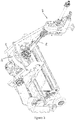
Figure 4 shows a side section through a portion of the baler and a portion of the PTO mechanism of the agricultural vehicle in which the connector elements are shown in a high ratio position; -
Figure 5 shows a schematic side section of the connector in which the connector elements are arranged in a low ratio position; -
Figure 6 shows a part sectional view through a portion of the connector; -
Figure 7 shows an exploded view of a portion of the connector; -
Figure 8 shows a schematic side section similar toFigure 5 illustrating the connector elements arranged in the high ratio position; and -
Figure 9 shows a part sectional view through a portion of the connector. - The invention will now be described in the following detailed description with reference to the drawings, wherein preferred embodiments are described in detail to enable practice of the invention. Although the invention is described with reference to these specific preferred embodiments, it will be understood that the invention is not limited to these preferred embodiments. But to the contrary, the invention includes numerous alternatives, modifications and equivalents as will become apparent from consideration of the following detailed description.
- Reference to terms such as longitudinal, transverse and vertical are made with respect to a longitudinal vehicle axis which is parallel to a normal forward direction of travel.
- With reference to
Figure 1 , a schematic side view of an agricultural vehicle connected to an agricultural implement by a connector in accordance with the present invention is shown. Reference should also be made toFigures 2 and3 . Abaler 2 is, in use, towed by an agricultural vehicle 4 such as a tractor. As it is towed, thebaler 2 is operable to receiveloose crop material 6 and to form the conveyed crop material into a substantiallyrectangular bale 8. The agricultural vehicle 4 is provided with a Power Take Off (or PTO) 10 operable to transfer mechanical power from anengine 12 of the agricultural vehicle 4 to thebaler 2. Thebaler 2 comprises aframe 14 mechanically coupled with the agricultural vehicle 4, a loose cropmaterial receiving component 16, a forming orbaling chamber 18, aplunger 20, a crankshaft, afly wheel 22, acommunication bus 24 extending between the agricultural vehicle 4 and thebaler 2 and anelectronic control unit 26. Additionally one ormore PTO sensors 28 and/or one or more plunger sensors may be provided. - The loose crop
material receiving component 16 may take any suitable form and include a pick up mechanism to pick up the loose crop material from the ground, a cutter mechanism to cut the loose crop material and a feeder or conveyor unit to direct the loose crop material into a stuffer chute connected to thebaling chamber 18. Thebaling chamber 18 is conveniently operable to receive the loose material from the stuffer chute and hold theloose crop material 6 as it is compressed by theplunger 20 into a growingbale 30. Thebaling chamber 18 is conveniently rectangular to facilitate the compression and forming process. - The
plunger 20 is operated to compress theloose crop material 6 as a result of a reciprocating movement within thebaling chamber 18. Forward movement of theplunger 20 compresses loose crop material present in thebaling chamber 18 and retraction allows further loose crop material to enter thebaling chamber 18 by way of the stuffer chute. A connecting rod 32 may connect theplunger 20 to the crankshaft. In turn the crankshaft is mechanically coupled to and operable to store and transfer power from thePTO 10 to theplunger 20. Typically theflywheel 22 is operable to store and release kinetic energy from the PTO in order to provide a greater inertial mass to smooth the operation of theplunger 20. - The
communication bus 24 is operable to communicate bi-directionally between the agricultural vehicle 4 and thebaler 2. Theelectronic control unit 26 may be operable to receive signals from sensors, such as the PTO and plunger sensors, and to send signals to control various elements of thebaler 2. - A
connection 40 between thePTO 10 and theflywheel 22 will now be described with particular reference toFigures 4 to 9 . Theconnection 40 comprises a housing 42, aninput shaft 44 provided with a displaceable gearedcollar 46, anoutput shaft 48 and an intermediate shaft 50. - The
input shaft 44 is connected to thePTO 10 to be rotatably driven in use by thePTO 10. The displaceable gearedcollar 46 is mounted about theinput shaft 44. The displaceable gearedcollar 46 is provided with individual first andsecond gears collar 46 is splined for lateral movement with respect to theinput shaft 44. - The displaceable geared
collar 46 may be induced to move axially with respect to theinput shaft 44 by an actuator. The actuator may be electric or hydraulic. A biasing element such as a spring acts on the displaceable gearedcollar 46 to maintain the displaceable gearedcollar 46 in the position shown inFigure 2 . The actuator is adapted to overcome the biasing element to move the displaceable gearedcollar 46 into the position shown inFigure 3 . - The intermediate shaft 50 conveniently takes the form of a cluster gear with first and
second gears - The
output shaft 48 is provided with agear 60 at a first end within thehousing 40. A second end of theoutput shaft 48 is connected by way of a directional clutch 62 to a first end of a cardanjoint driveshaft 64. The directional clutch 62 aids the shifting of the displaceable gearedcollar 46 by allowing the shafts internal to the gearbox internal to the gearbox to remain stationary (that is, without rotation) via the application of the PTO brake of the agricultural vehicle while the cardanjoint driveshaft 64 and all other baler drive components rotate. This eliminates the need for synchronizers and clutches since the shift operation is performed on a static geartrain. A second end of thedriveshaft 64 is connected to theflywheel 22. - It will be understood that the ratio of the
second gears first gears - In operation, the connector elements initially adopt the position shown in
Figures 5 to 7 , that is a low ratio position. This allows for a large mechanical advantage between thePTO 10 and theflywheel 22 on start up. On start up, thePTO 10 is engaged, and once thetractor engine 12 has recovered from the initial engagement, and theflywheel 22 has attained a desired initial velocity, thePTO 10 is then switched off. Theelectronic control unit 26 may be provided with signals from sensors to confirm that the desired condition has been achieved and so signal thePTO 10 to switch off. The PTO brake on the tractor is applied thereby causing theinput shaft 44 to stop while the directional clutch 62 allows thebaler flywheel 22 to continue rotating. - The actuator is then signalled and operated to cause the displaceable geared
collar 46 to be moved to a high ratio position shown inFigures 4 ,8 and9 . Once the displaceable gearedcollar 46 is in this position, a signal is sent to engage the PTO clutch on the tractor 4 and thebaler flywheel 22 is then driven and accelerated to full operational speed. - It will be understood that the use of different gears in producing the desired gear ratios results in less wear of the PTO clutch involved in comparison to a use of single gear ratio. Further, use of a lower initial gear ratio than would be desirable in using a fixed gear ratio, enables an easier start to the baler mechanism and so less wear on the PTO clutch.
- In an alternative embodiment (not shown) the input shaft may be provided with a fixed gear arrangement and the intermediate shaft provided with an axially displaceable geared collar. In a further embodiment, not shown, the actuator is adapted to displace the clustered gear collar.
- From reading the present disclosure, other modifications will be apparent to persons skilled in the art. Such modifications may involve other features which are already known in the field of square balers and component parts therefore and which may be used instead of or in addition to features already described herein.
Claims (7)
- A baler comprises a flywheel connected by a cardan coupling to a connector to be connected to a PTO of a tractor, so that the flywheel may be driven by the PTO, in which the connector comprises
a housing;
an input shaft to be connected to the PTO mounted for rotation in a first part of the housing;
an output shaft to be connected to the cardan coupling, the output shaft being mounted for rotation in a second part of the housing;
an intermediate gear being mounted for rotation in the housing between the input shaft and the output shaft, the intermediate gear being disposed parallel to the input shaft and adapted to drive the output shaft;
wherein the input shaft is provided with a displaceable geared collar adapted to engage the intermediate gear with either a first lower gear ratio or a second higher gear ratio. - A baler according to claim 1, in which the intermediate gear comprises a gear cluster.
- A baler according to claim 1 or claim 2, in which the displaceable geared collar comprises a gear cluster.
- A baler according to any of claims 1 to claim 3, in which the connector further comprises an axial shift mechanism to shift the displaceable geared collar with respect to the input shaft.
- A baler according to claim 4, in which the axial shift mechanism comprises an electrical or hydraulic actuator.
- A baler according to any of claim 1 to claim 5, in which the output shaft is connected to the cardan coupling by way of a directional clutch.
- A method of initiating a baler in accordance with claim 1, the method comprising the steps of:initiating the PTO with the displaceable geared collar adapted to engage the intermediate gear with the first lower gear ratio;detecting when the flywheel has attained a desired initial velocity;switching off the PTO;operating the actuator to cause the displaceable geared collar to engage the intermediate gear with the higher gear ratio; andre-engaging the PTO.
Applications Claiming Priority (1)
| Application Number | Priority Date | Filing Date | Title |
|---|---|---|---|
| US201962955680P | 2019-12-31 | 2019-12-31 |
Publications (2)
| Publication Number | Publication Date |
|---|---|
| EP3845054A1 true EP3845054A1 (en) | 2021-07-07 |
| EP3845054B1 EP3845054B1 (en) | 2024-02-14 |
Family
ID=73855267
Family Applications (1)
| Application Number | Title | Priority Date | Filing Date |
|---|---|---|---|
| EP20214896.1A Active EP3845054B1 (en) | 2019-12-31 | 2020-12-17 | Baling apparatus |
Country Status (2)
| Country | Link |
|---|---|
| US (1) | US20210195842A1 (en) |
| EP (1) | EP3845054B1 (en) |
Citations (4)
| Publication number | Priority date | Publication date | Assignee | Title |
|---|---|---|---|---|
| EP0819374A1 (en) * | 1996-07-16 | 1998-01-21 | Usines Claas France S.A. | Gear drive for big balers |
| EP2901845A1 (en) * | 2014-01-30 | 2015-08-05 | Deere & Company | Sensor assembly and computer-implemented method |
| EP3398427A1 (en) * | 2017-05-05 | 2018-11-07 | CNH Industrial Italia S.p.A. | Agricultural system with a square baler controlled via a continuously variable transmission |
| WO2019180040A1 (en) * | 2018-03-23 | 2019-09-26 | Cnh Industrial Belgium Nv | Agricultural baler and method of protecting such baler from overload damage |
Family Cites Families (3)
| Publication number | Priority date | Publication date | Assignee | Title |
|---|---|---|---|---|
| DE19734962A1 (en) * | 1997-08-13 | 1999-02-18 | Fischer Herwig | Overriding clutch with drive and driven element |
| BE1021141B1 (en) * | 2013-04-15 | 2016-01-08 | Cnh Industrial Belgium Nv | FLYWHEEL START-UP SYSTEM |
| EP3646717B1 (en) * | 2018-11-02 | 2023-03-22 | CNH Industrial Belgium NV | A baling machine including a drive-transferring driveline |
-
2020
- 2020-12-17 EP EP20214896.1A patent/EP3845054B1/en active Active
- 2020-12-30 US US17/138,671 patent/US20210195842A1/en active Pending
Patent Citations (4)
| Publication number | Priority date | Publication date | Assignee | Title |
|---|---|---|---|---|
| EP0819374A1 (en) * | 1996-07-16 | 1998-01-21 | Usines Claas France S.A. | Gear drive for big balers |
| EP2901845A1 (en) * | 2014-01-30 | 2015-08-05 | Deere & Company | Sensor assembly and computer-implemented method |
| EP3398427A1 (en) * | 2017-05-05 | 2018-11-07 | CNH Industrial Italia S.p.A. | Agricultural system with a square baler controlled via a continuously variable transmission |
| WO2019180040A1 (en) * | 2018-03-23 | 2019-09-26 | Cnh Industrial Belgium Nv | Agricultural baler and method of protecting such baler from overload damage |
Also Published As
| Publication number | Publication date |
|---|---|
| EP3845054B1 (en) | 2024-02-14 |
| US20210195842A1 (en) | 2021-07-01 |
Similar Documents
| Publication | Publication Date | Title |
|---|---|---|
| US10517222B2 (en) | Drive arrangement for powering the plunger of an agricultural baler | |
| EP2958421B1 (en) | Baler with start-up control system | |
| EP1974601B1 (en) | Large baling press | |
| US20140137757A1 (en) | Agricultural implement with power input having continuously variable transmission | |
| EP3563665B1 (en) | Rectangular bale press with counterweight which compensates for the movement of the stamp | |
| EP3563663B1 (en) | High density plunger movement | |
| EP3845054A1 (en) | Baling apparatus | |
| US20210251147A1 (en) | Agricultural baling machine | |
| EP2206424B1 (en) | Plunger drive and large square baler | |
| RU2682442C2 (en) | Square baler | |
| EP4201193A1 (en) | Stuffer assembly for an agricultural baler | |
| US11871701B2 (en) | Baling machine including a drive-transferring driveline | |
| US20230077734A1 (en) | Gear assembly for driving a ram of a square baler | |
| EP4169371A1 (en) | Baler and a rotary drive transmission for a baler | |
| EP3819724A1 (en) | Agricultural system |
Legal Events
| Date | Code | Title | Description |
|---|---|---|---|
| PUAI | Public reference made under article 153(3) epc to a published international application that has entered the european phase |
Free format text: ORIGINAL CODE: 0009012 |
|
| STAA | Information on the status of an ep patent application or granted ep patent |
Free format text: STATUS: THE APPLICATION HAS BEEN PUBLISHED |
|
| AK | Designated contracting states |
Kind code of ref document: A1 Designated state(s): AL AT BE BG CH CY CZ DE DK EE ES FI FR GB GR HR HU IE IS IT LI LT LU LV MC MK MT NL NO PL PT RO RS SE SI SK SM TR |
|
| STAA | Information on the status of an ep patent application or granted ep patent |
Free format text: STATUS: REQUEST FOR EXAMINATION WAS MADE |
|
| 17P | Request for examination filed |
Effective date: 20220107 |
|
| RBV | Designated contracting states (corrected) |
Designated state(s): AL AT BE BG CH CY CZ DE DK EE ES FI FR GB GR HR HU IE IS IT LI LT LU LV MC MK MT NL NO PL PT RO RS SE SI SK SM TR |
|
| P01 | Opt-out of the competence of the unified patent court (upc) registered |
Effective date: 20230518 |
|
| GRAP | Despatch of communication of intention to grant a patent |
Free format text: ORIGINAL CODE: EPIDOSNIGR1 |
|
| STAA | Information on the status of an ep patent application or granted ep patent |
Free format text: STATUS: GRANT OF PATENT IS INTENDED |
|
| INTG | Intention to grant announced |
Effective date: 20231019 |
|
| GRAS | Grant fee paid |
Free format text: ORIGINAL CODE: EPIDOSNIGR3 |
|
| GRAA | (expected) grant |
Free format text: ORIGINAL CODE: 0009210 |
|
| STAA | Information on the status of an ep patent application or granted ep patent |
Free format text: STATUS: THE PATENT HAS BEEN GRANTED |
|
| AK | Designated contracting states |
Kind code of ref document: B1 Designated state(s): AL AT BE BG CH CY CZ DE DK EE ES FI FR GB GR HR HU IE IS IT LI LT LU LV MC MK MT NL NO PL PT RO RS SE SI SK SM TR |
|
| REG | Reference to a national code |
Ref country code: GB Ref legal event code: FG4D |
|
| REG | Reference to a national code |
Ref country code: CH Ref legal event code: EP |
|
| REG | Reference to a national code |
Ref country code: DE Ref legal event code: R096 Ref document number: 602020025603 Country of ref document: DE |
|
| REG | Reference to a national code |
Ref country code: IE Ref legal event code: FG4D |