EP3845050A1 - Methods and systems for measuring organic material throughput data of harvested crops - Google Patents
Methods and systems for measuring organic material throughput data of harvested crops Download PDFInfo
- Publication number
- EP3845050A1 EP3845050A1 EP20189573.7A EP20189573A EP3845050A1 EP 3845050 A1 EP3845050 A1 EP 3845050A1 EP 20189573 A EP20189573 A EP 20189573A EP 3845050 A1 EP3845050 A1 EP 3845050A1
- Authority
- EP
- European Patent Office
- Prior art keywords
- organic material
- data
- crop
- combine harvester
- material throughput
- Prior art date
- Legal status (The legal status is an assumption and is not a legal conclusion. Google has not performed a legal analysis and makes no representation as to the accuracy of the status listed.)
- Granted
Links
Images



Classifications
-
- A—HUMAN NECESSITIES
- A01—AGRICULTURE; FORESTRY; ANIMAL HUSBANDRY; HUNTING; TRAPPING; FISHING
- A01B—SOIL WORKING IN AGRICULTURE OR FORESTRY; PARTS, DETAILS, OR ACCESSORIES OF AGRICULTURAL MACHINES OR IMPLEMENTS, IN GENERAL
- A01B79/00—Methods for working soil
- A01B79/005—Precision agriculture
-
- G—PHYSICS
- G01—MEASURING; TESTING
- G01F—MEASURING VOLUME, VOLUME FLOW, MASS FLOW OR LIQUID LEVEL; METERING BY VOLUME
- G01F1/00—Measuring the volume flow or mass flow of fluid or fluent solid material wherein the fluid passes through a meter in a continuous flow
-
- A—HUMAN NECESSITIES
- A01—AGRICULTURE; FORESTRY; ANIMAL HUSBANDRY; HUNTING; TRAPPING; FISHING
- A01C—PLANTING; SOWING; FERTILISING
- A01C21/00—Methods of fertilising, sowing or planting
- A01C21/007—Determining fertilization requirements
-
- A—HUMAN NECESSITIES
- A01—AGRICULTURE; FORESTRY; ANIMAL HUSBANDRY; HUNTING; TRAPPING; FISHING
- A01D—HARVESTING; MOWING
- A01D41/00—Combines, i.e. harvesters or mowers combined with threshing devices
- A01D41/12—Details of combines
- A01D41/127—Control or measuring arrangements specially adapted for combines
- A01D41/1271—Control or measuring arrangements specially adapted for combines for measuring crop flow
-
- A—HUMAN NECESSITIES
- A01—AGRICULTURE; FORESTRY; ANIMAL HUSBANDRY; HUNTING; TRAPPING; FISHING
- A01D—HARVESTING; MOWING
- A01D41/00—Combines, i.e. harvesters or mowers combined with threshing devices
- A01D41/12—Details of combines
- A01D41/127—Control or measuring arrangements specially adapted for combines
- A01D41/1271—Control or measuring arrangements specially adapted for combines for measuring crop flow
- A01D41/1272—Control or measuring arrangements specially adapted for combines for measuring crop flow for measuring grain flow
-
- A—HUMAN NECESSITIES
- A01—AGRICULTURE; FORESTRY; ANIMAL HUSBANDRY; HUNTING; TRAPPING; FISHING
- A01D—HARVESTING; MOWING
- A01D41/00—Combines, i.e. harvesters or mowers combined with threshing devices
- A01D41/12—Details of combines
- A01D41/127—Control or measuring arrangements specially adapted for combines
- A01D41/1277—Control or measuring arrangements specially adapted for combines for measuring grain quality
-
- A—HUMAN NECESSITIES
- A01—AGRICULTURE; FORESTRY; ANIMAL HUSBANDRY; HUNTING; TRAPPING; FISHING
- A01F—PROCESSING OF HARVESTED PRODUCE; HAY OR STRAW PRESSES; DEVICES FOR STORING AGRICULTURAL OR HORTICULTURAL PRODUCE
- A01F12/00—Parts or details of threshing apparatus
- A01F12/10—Feeders
-
- A—HUMAN NECESSITIES
- A01—AGRICULTURE; FORESTRY; ANIMAL HUSBANDRY; HUNTING; TRAPPING; FISHING
- A01F—PROCESSING OF HARVESTED PRODUCE; HAY OR STRAW PRESSES; DEVICES FOR STORING AGRICULTURAL OR HORTICULTURAL PRODUCE
- A01F12/00—Parts or details of threshing apparatus
- A01F12/18—Threshing devices
-
- G—PHYSICS
- G01—MEASURING; TESTING
- G01G—WEIGHING
- G01G11/00—Apparatus for weighing a continuous stream of material during flow; Conveyor belt weighers
-
- A—HUMAN NECESSITIES
- A01—AGRICULTURE; FORESTRY; ANIMAL HUSBANDRY; HUNTING; TRAPPING; FISHING
- A01B—SOIL WORKING IN AGRICULTURE OR FORESTRY; PARTS, DETAILS, OR ACCESSORIES OF AGRICULTURAL MACHINES OR IMPLEMENTS, IN GENERAL
- A01B39/00—Machines specially adapted for working soil on which crops are growing
- A01B39/12—Machines specially adapted for working soil on which crops are growing for special purposes, e.g. for special culture
- A01B39/18—Machines specially adapted for working soil on which crops are growing for special purposes, e.g. for special culture for weeding
-
- A—HUMAN NECESSITIES
- A01—AGRICULTURE; FORESTRY; ANIMAL HUSBANDRY; HUNTING; TRAPPING; FISHING
- A01B—SOIL WORKING IN AGRICULTURE OR FORESTRY; PARTS, DETAILS, OR ACCESSORIES OF AGRICULTURAL MACHINES OR IMPLEMENTS, IN GENERAL
- A01B39/00—Machines specially adapted for working soil on which crops are growing
- A01B39/20—Tools; Details
-
- A—HUMAN NECESSITIES
- A01—AGRICULTURE; FORESTRY; ANIMAL HUSBANDRY; HUNTING; TRAPPING; FISHING
- A01B—SOIL WORKING IN AGRICULTURE OR FORESTRY; PARTS, DETAILS, OR ACCESSORIES OF AGRICULTURAL MACHINES OR IMPLEMENTS, IN GENERAL
- A01B69/00—Steering of agricultural machines or implements; Guiding agricultural machines or implements on a desired track
- A01B69/001—Steering by means of optical assistance, e.g. television cameras
-
- G—PHYSICS
- G01—MEASURING; TESTING
- G01G—WEIGHING
- G01G11/00—Apparatus for weighing a continuous stream of material during flow; Conveyor belt weighers
- G01G11/08—Apparatus for weighing a continuous stream of material during flow; Conveyor belt weighers having means for controlling the rate of feed or discharge
- G01G11/083—Apparatus for weighing a continuous stream of material during flow; Conveyor belt weighers having means for controlling the rate of feed or discharge of the weight-belt or weigh-auger type
-
- G—PHYSICS
- G01—MEASURING; TESTING
- G01V—GEOPHYSICS; GRAVITATIONAL MEASUREMENTS; DETECTING MASSES OR OBJECTS; TAGS
- G01V99/00—Subject matter not provided for in other groups of this subclass
Definitions
- Producers planting, growing, and harvesting crops track certain data and metrics to inform future planting and treatment decisions such as how much seed to apply in a subsequent harvest, which crop or crop varietal to plant, and what type and how much soil conditioner or fertilizer to use, among other planting and treatment decisions.
- One common type of data used for this purpose is crop yield data.
- agricultural implements and machinery include yield monitoring systems that measure the weight or volume of the crop yield as the crop is being harvested, which can later be reviewed by the producer as indicative of the health of the crop and the efficiency of planting and fertilizer techniques, which in turn aids in making a planting or treatment decision for subsequent harvests.
- a producer is unable to determine the true health of a field or crop or else make accurate prescription planting and fertilizer decisions based on yield data alone. For example, sometimes crop yield and total crop volume will not directly correlate. Thus, a rather healthy-looking crop may result in a relatively low yield, or conversely a rather unhealthy-looking crop may in fact result in a relatively high yield. Relying solely on yield data can result in less-than-optimal planting or treatment decisions.
- the present invention is directed to methods and systems for collecting organic material throughput data and using the organic material throughput data instead of or in addition to other crop data and metrics, such a crop yield data, when making a planting or treatment decision. More particularly, the invention is directed to measuring the total relative harvested crop volume and, in some embodiments, making subsequent planting or treatment decisions based on the total relative harvested crop volume.
- some embodiments of the invention are directed to a method of monitoring a throughput of a crop.
- the method may include cutting organic material using a combine harvester and conveying the organic material through the combine harvester to a threshing mechanism located within the combine harvester.
- an organic material throughput sensor senses organic material throughput data, which may be at least one of a volume of the organic material and a weight of the organic material.
- the organic material throughput data is transmitted to a data management system, which outputs an organic material throughput map based on the organic material throughput data.
- inventions of the invention are directed to a method of monitoring a throughput of a crop.
- the method includes cutting a first set of organic material using a combine harvester, conveying the first set of organic material through the combine harvester to a threshing mechanism located within the combine harvester, and, prior to the first set of organic material being conveyed through the threshing mechanism, sensing, using an organic material throughput sensor, a first organic material throughput data including at least one of a volume of the first set of organic material and a weight of the first set of organic material.
- the method further includes cutting a second set of organic material using the combine harvester, conveying the second set of organic material through the combine harvester to the threshing mechanism, and, prior to the second set of organic material being conveyed through the threshing mechanism, sensing, using the organic material throughput sensor, second organic material throughput data including at least one of a volume of the second set of organic material and a weight of the second set of organic material.
- the method may include determining, based on a comparison of the first organic material throughput data and the second organic material throughput data, at least one of a type of crop to plant in a field, an amount of seed to plant in the field, a type of fertilizer to apply to the field, and an amount of fertilizer to apply to the field.
- Still other embodiments of the invention are directed to a system for monitoring a throughput of a crop.
- the system may include a combine harvester including a feeder box, a main body downstream of the feeder box, a threshing mechanism within the main body, and an organic material throughput sensor provided within the feeder box.
- the system may also include a data management system remote from the combine harvester.
- the organic material throughput sensor senses organic material throughput data including at least one of a volume of the organic material, and a weight of the organic material and the data management system outputs an organic material throughput map based on the organic material throughput data.
- aspects of the invention are directed to a methods and systems for collecting organic material throughput data and using the same instead of, or else in addition to, other data such as crop yield data when making a planting or treatment decision. More particularly, the invention is directed to measuring the total relative harvested crop volume, which correlates to the overall spread organic matter in the field, and making a planting or treatment decision in light of the same.
- a producer, grower, or other user can use the organic material throughput data to, for example, build maps relating organic soil health directly to harvested organic volume and thus a prescription map can be compiled for adding organic material to the areas lacking.
- crop yield and crop volume do not always correlate.
- the mapped organic material throughput data thus provides a producer the ability to determine crop varieties efficiencies based on yield, fertilizer consumption, and total plant mass. Still more, crop residue is often removed from the field by several different methods including bailing, burning, and grazing, among others. This removed material results in the reduction of the number of micro- and macro-nutrients in the soil.
- the producer can replace these nutrients as required without the using a soil map.
- using the organic material throughput data gives the producer the ability to map organic matter over time, which can be applied to future soil health goals.
- FIG. 1 shows a combine harvester 10 that may employ various aspects of the invention.
- the combine harvester 10 generally includes a main body 12 housing various crop threshing, cleaning, transporting, and storage equipment as will be discussed in more detail below.
- the main body 12 supports front drive wheels or tracks 14, rear steering wheels 16, and an operator's cab 34 at a front portion of the combine harvester 10.
- Extending from a front of the main body 12 is a feeder house 18 operatively coupled to a crop gathering header 20.
- the feeder house 18 feeds cut organic material into an interior of the main body 12 during operation of the combine harvester 10, while the crop gathering header 20 gathers, cuts, and conveys the organic material to the feeder house 18.
- the crop gathering header 20 includes various cutting and transporting mechanisms used to sever the organic material from a field and direct the organic material towards the feeder house 18.
- the crop gathering header 20 includes a reel 22 and auger 24.
- the reel 22 rotates and severs the crop being harvested from the field.
- the spinning auger 24 then transports the cut organic material towards a center of the combine harvester 10, and more particularly towards an opening 25 in the rear wall of the crop gathering header 20 that is aligned with an open inlet 37 of the outer casing 36 of the feeder house 18 ( FIG. 2 ).
- the feeder house 18 in turn conveys the organic material into an interior of the main body 12 via an elevator 38. More particularly, the rotating elevator 38 engages the cut organic material and transports it generally upwards and backwards, towards an open outlet of the outer casing 36 of the feeder house 18.
- the cut organic material is first fed to a threshing mechanism 26.
- the threshing mechanism 26 includes various cylinders, concaves, separators, pans, sieves, cleaners, and other mechanisms for separating grain or other harvested crop from the straw, chaff, and other byproducts of the cut organic material.
- the separated grain or harvested crop is then carried via an elevator or the like to a grain tank 28 in the main body 12, while the straw, chaff, and other byproducts are exhausted from a back end of the combine harvester 10 to be later baled or otherwise removed from the field, or else stored in a straw tank 30 for later removal.
- the grain tank 28 is at or near capacity, the grain is unloaded into a trailer or cart via the unloading tube 32.
- the combine harvester 10 may include a yield sensor 27 to monitor the yield of the crop being harvested.
- the yield sensor 27 may be, for example, an optical or weight sensor that measures the amount of grain or the like being transported to the grain tank 28 as the combine harvester 10 operates. This yield data can then be relayed in real-time to an operator within the operator's cab 34 so that the operator knows when the grain tank 28 needs to be emptied. Or the yield data may be stored via an on-board memory for later uploading to a data management system such as a Farm Management Information System (FMIS) or other suitable program, or else transmitted wirelessly by a wireless communication system on the combine harvester to the data management or similar system.
- FMIS Farm Management Information System
- the data management or similar system in turn is configured to output the data in tabular format, in a map format, or in another desired format for an end-user to review and make planting or treatment decisions in light of the same.
- FIG. 3 depicts a yield map 42 graphically depicting the yield from a plurality of zones of a harvested field as one example of a yield map that may be generated by the data management or similar system.
- the yield map 42 uses different density cross-hatching to graphically represent the yield harvested.
- zones without cross-hatching or with relatively little cross hatching such as zone 46 located at A-6 of the yield map 42's grid, yielded a relatively low amount of crop
- zones with relatively dense cross-hatching such as zone 44 located at G-5 of the yield map 42's grid
- Farm operators can in turn use the yield map or similar data to make appropriate decisions regarding fertilizer application, soil conditioning, and other decisions to ensure a more productive crop in future plantings.
- embodiments of the invention include an organic material throughput sensor 40 that senses a total throughput of organic material passing through the combine harvester 10. Unlike the yield sensor 27, which only measures a mass, weight, volume, or other metric of the grain or harvested crop, the organic material throughput sensor 40 measures a mass, weight, volume, or other metric of the total organic material cut and removed from the field being harvested. This data can then be used in addition to, or in some instances in combination with, the yield sensor 27 data to make more informed decisions about fertilization, soil conditioning, and others as will be described in more detail below. As with the yield data, in some embodiments the organic material throughput data can be provided to an operator in real-time such as via a user interface within the cab 34 of the combine harvester 10.
- the organic material throughput sensor 40 is provided in the feeder house 18 of the combine harvester 10.
- the organic material throughput sensor 40 can be any desired type of sensor capable of detecting a volume, mass, weight, or other desired metric of the organic material passing through the feeder house 18.
- the organic material throughput sensor 40 may be an optical sensor that visually detects a volume of the organic material passing thereby.
- the organic material throughput sensor 40 may be a weight sensor operatively coupled to the feeder house 18 elevator 38 that detects a weight of the material being transported by the elevator 38.
- Other types of sensors can be implemented without departing from the scope of the invention.
- the data logged by the organic material throughput sensor 40 can be provided to an operator in real time, can be stored on-board via a memory device or the like, and/or can be transmitted or uploaded to a data management system (e.g., FMIS software package or other program) for analysis.
- a data management system e.g., FMIS software package or other program
- using the organic material throughput data that data management system generates an organic material throughput map 48 such as that shown in FIG. 4 . More particularly, FIG. 4 depicts an organic material throughput map 48 that graphically depicts the total organic material removed from a plurality of zones of a harvested field as one example of an organic material throughput map that may be generated by the data management system.
- the organic material throughput map 48 cross-hatches different zones according to the amount of organic material removed from the field at the corresponding location.
- zones or zones with relatively low amounts of cross-hatching such as zone 49 located at D-3 of the map 48's grid, a relatively low amount of organic material was removed from the field
- zones including relatively dense cross hatching such as zone 52 located at A-6 of the map 48's grid
- the data provided by the organic material throughput map 48 provides producers and other growers with a more complete view of the health of a given field or crop, which in turn aids the producer in making future fertilization, soil conditioning, and other decisions. More particularly, by having access to the organic material throughput map 48 in addition to the yield map 42, the producer has more complete agronomic data showing the health of a field or the condition of the soil. This is particularly useful because there is not always a correlation between yield and total crop mass, as both crop mass and yield may vary throughout the field, independent of each other. Capturing the total crop material throughput provides an additional data set for use by the producer to make future decisions.
- FIGS. 5-8 are flowcharts schematically representing methods of using crop data such as data logged by the organic material throughput sensor 40 according to some embodiments of the invention.
- FIG. 5 is a flowchart schematically representing a method 54 of making a planting decision or a treatment decision based on the organic material throughput data.
- a producer may wish to apply an amount of fertilizer to a field proportional to the amount of total organic material removed from the field.
- a producer can make an informed decision regarding how much fertilizer to thereafter add to a field.
- a producer or other operator cuts a crop in a field using a combine harvester, such as the combine harvester 10 described in connection with FIG. 1 .
- the cut crop is conveyed to a central portion of the crop gathering header 20, proximate an opening 25 in the rear wall of the crop gathering header 20.
- the cut crop is then conveyed through the feeder box 18, and more particularly through an open inlet 37 of the outer casing of the feeder box 18, through an interior of the feeder box 18, and then through an open outlet of the outer casing 36 for later conveying through various stages of the combine harvester 10 including a threshing mechanism 26.
- the organic material throughput is sensed using any desired sensor such as an optical, weight, or mass sensor 40.
- the data from the sensor is stored in any desired format via on on-board memory device or the like or else is transmitted wirelessly for storage at a remote location such as a centralized server, personal computer, or similar device having a suitable memory device.
- the data from the sensor is uploaded into a data management system such as a FMIS software package or the like for review by a producer.
- the software package may output the data graphically in the form of an organic mass throughput map such as the map 48 discussed in connection with FIG. 4 .
- the producer makes at least one of a planting and treatment decision based on its review of the data.
- the planting and/or treatment decision may be one of which type of crop and/or varietal to plant, or may be what type and/or quantity of fertilizer to apply to the field.
- the producer may determine how much total fertilizer should be applied the harvested field based on the total amount of organic material removed from the filed during the harvesting.
- the producer may determine where to selectively apply fertilizer in the field according to the data.
- a producer may desire to apply more fertilizer in areas of the field where the most organic material was removed during harvesting.
- the producer may thus decide to apply more fertilizer to areas where there was a relatively large volume of organic material remove-such as zone 52 in the organic mass throughput map 48-and apply less fertilizer to areas where there was a relatively low volume of organic material removed-such as zone 49 in the organic mass throughput map 48.
- the producer may make a planting, treatment, or other decision based on material throughput data over time. This may replace or else augment the need to take soil samples of a field, which are traditionally used to make fertilizer and other treatment decisions. More particularly, FIG. 6 is a flowchart schematically representing a method 68 of determining how much or what type of fertilizer to apply to a field using material throughput data over time.
- a producer cuts a crop, conveys it to and through a feeder box of a combine harvester, senses the organic material throughput with a sensor in the feeder box, and uploads the sensor data to a software package or the like in a similar manner as described about with respect to steps 56, 58, 60, 62, and 64 of method 54, which thus will not be repeated in detail.
- steps 70, 72, 74, 76, and 78 are repeated such that the producer has data for two or more successive harvests. Namely, at step 80, when more data is to be collected for a time lapse comparison, steps 70, 72, 74, 76, and 78 are repeated for a successive harvest. Once enough data has been collected for a time-lapse comparison-i.e., once data has been collected for two or more harvests-the method proceeds to step 82, where a data management system generates material throughput maps or other time-lapse data detailing the organic material throughput over time.
- a producer makes a planting or treatment decision based on the data outputted at step 82. For example, in some embodiments the producer determines an amount or type of fertilizer to apply to a field based on the data outputted at step 82. In such embodiments, the producer may decide to apply a first type and/or amount of fertilizer if the data shows a steadily decreasing material throughput from a particular field over time. Or the producer may decide to apply a second type and/or amount of fertilizer if the data shows a steadily increasing material throughput from a particular field over time. Still more, the producer may decide to apply a third type and/or amount of fertilizer if the data shows a relatively steady material throughput from a particular field over time. By utilizing the time lapse data in such a fashion, the producer may be able to replace, or else augment, soil sampling traditionally carried out to make such fertilization decisions.
- the producer may make a planting decision based on a comparison of material throughput data for a plurality of crops and/or varietals of crops. More particularly, FIG. 7 is a flowchart schematically representing a method 86 of determining which crop or crop varietal using organic material throughput data.
- a producer cuts a crop, conveys it to and through a feeder box of a combine harvester, senses the organic material throughput with a sensor in the feeder box, and uploads the sensor data to a data management system such as FMIS software or the like in a similar manner as described about with respect to steps 56, 58, 60, 62, and 64 of method 54, which thus will not be described again in detail.
- a data management system such as FMIS software or the like
- steps 88, 90, 92, 94, and 96 of method 86 are repeated such that the producer has data for two or more crops and/or crop varietals.
- steps 88, 90, 92, 94, and 96 are repeated for a different crop and/or crop varietal.
- data may be collected for a different field in which a different crop or crop varietal was planted, or data may be collected in a successive harvest for the same field but for which a different crop or crop varietal was planted.
- step 100 the data management system generates material throughput maps or other graphical output detailing the data collected from the material throughput sensor. For example, in some embodiments at least two different organic material throughput maps-similar to the map 48 shown in FIG. 4 -are generated, one for each crop and/or crop varietal being compared. The producer or other user is then able to quickly visualize and compare the performance of each crop and/or crop varietal. For example, in some embodiments a first set of data is collected for a first wheat hybrid and a second set of data is collected for a second wheat hybrid.
- a producer may compare, among other data, the organic material throughput map for the first wheat hybrid with the organic material throughput map for the second wheat hybrid.
- This data may provide the producer a more useful side-by-side comparison of crop hybrids than known comparisons. More particularly, instead of just comparing yield, this data enables producers to compare total plant mass for each varietal.
- the producer may make a crop planting and/or treatment decision based on both sensed yield and total organic material throughput.
- FIG. 8 is a flowchart schematically representing a method 104 of making a planting or treatment decision based on at least two different metrics for a single crop; in this case, total organic material and crop yield.
- a producer cuts a crop, conveys it to and through a feeder box of a combine harvester, and senses the organic material throughput with a sensor in the feeder box in a similar manner as described above with respect to steps 56, 58, 60, and 62 of method 54, which thus will not be described again in detail.
- the cut material is then conveyed through a threshing and/or cleaning mechanism, such as the threshing mechanism 26 described in connection with the combine harvester 10. Again, the threshing and/or cleaning mechanism separates the harvested crop (e.g., grain) from the byproducts (e.g., straw, chaff, etc.).
- a yield sensor such as yield sensor 27 discussed above in connection with combine harvester 10 senses the yield of the harvested crop.
- the data from the organic material throughput sensor and yield sensor is uploaded to the data management system such as the FMIS software discussed above.
- a producer or the like makes one of a planting and/or a treatment decision based at least in part on data from the organic material throughput sensor and the yield sensor.
- the data management system may output the yield data and the organic material throughput data in the form of a yield map (similar to that shown in FIG. 3 ) and an organic material throughput map (similar to that shown in FIG. 4 ).
- the producer makes one of a planting decision and a treatment decision based at least in part on the yield map and the organic material throughput map.
- the producer may thereafter plant a different crop varietal and/or apply a different amount or type of fertilizer in an effort to improve yield in subsequent harvests.
- the two sets of data provide a more complete set of data to the producer in order to make more informed planting and/or treatment decisions.
Landscapes
- Life Sciences & Earth Sciences (AREA)
- Environmental Sciences (AREA)
- Soil Sciences (AREA)
- Physics & Mathematics (AREA)
- General Physics & Mathematics (AREA)
- Fluid Mechanics (AREA)
- Engineering & Computer Science (AREA)
- Mechanical Engineering (AREA)
- Management, Administration, Business Operations System, And Electronic Commerce (AREA)
- Fertilizing (AREA)
Abstract
Description
- Producers planting, growing, and harvesting crops track certain data and metrics to inform future planting and treatment decisions such as how much seed to apply in a subsequent harvest, which crop or crop varietal to plant, and what type and how much soil conditioner or fertilizer to use, among other planting and treatment decisions. One common type of data used for this purpose is crop yield data. In this regard, agricultural implements and machinery include yield monitoring systems that measure the weight or volume of the crop yield as the crop is being harvested, which can later be reviewed by the producer as indicative of the health of the crop and the efficiency of planting and fertilizer techniques, which in turn aids in making a planting or treatment decision for subsequent harvests.
- Often, however, a producer is unable to determine the true health of a field or crop or else make accurate prescription planting and fertilizer decisions based on yield data alone. For example, sometimes crop yield and total crop volume will not directly correlate. Thus, a rather healthy-looking crop may result in a relatively low yield, or conversely a rather unhealthy-looking crop may in fact result in a relatively high yield. Relying solely on yield data can result in less-than-optimal planting or treatment decisions.
- There thus remains a need to provide a producer with more complete crop metrics or data in order for the producer to make more informed planting, treatment, and other crop-related decisions.
- The present invention is directed to methods and systems for collecting organic material throughput data and using the organic material throughput data instead of or in addition to other crop data and metrics, such a crop yield data, when making a planting or treatment decision. More particularly, the invention is directed to measuring the total relative harvested crop volume and, in some embodiments, making subsequent planting or treatment decisions based on the total relative harvested crop volume.
- For example, some embodiments of the invention are directed to a method of monitoring a throughput of a crop. The method may include cutting organic material using a combine harvester and conveying the organic material through the combine harvester to a threshing mechanism located within the combine harvester. Prior to the organic material being conveyed through the threshing mechanism, an organic material throughput sensor senses organic material throughput data, which may be at least one of a volume of the organic material and a weight of the organic material. The organic material throughput data is transmitted to a data management system, which outputs an organic material throughput map based on the organic material throughput data.
- Other embodiments of the invention are directed to a method of monitoring a throughput of a crop. The method includes cutting a first set of organic material using a combine harvester, conveying the first set of organic material through the combine harvester to a threshing mechanism located within the combine harvester, and, prior to the first set of organic material being conveyed through the threshing mechanism, sensing, using an organic material throughput sensor, a first organic material throughput data including at least one of a volume of the first set of organic material and a weight of the first set of organic material. The method further includes cutting a second set of organic material using the combine harvester, conveying the second set of organic material through the combine harvester to the threshing mechanism, and, prior to the second set of organic material being conveyed through the threshing mechanism, sensing, using the organic material throughput sensor, second organic material throughput data including at least one of a volume of the second set of organic material and a weight of the second set of organic material. In some embodiments, the method may include determining, based on a comparison of the first organic material throughput data and the second organic material throughput data, at least one of a type of crop to plant in a field, an amount of seed to plant in the field, a type of fertilizer to apply to the field, and an amount of fertilizer to apply to the field.
- Still other embodiments of the invention are directed to a system for monitoring a throughput of a crop. The system may include a combine harvester including a feeder box, a main body downstream of the feeder box, a threshing mechanism within the main body, and an organic material throughput sensor provided within the feeder box. The system may also include a data management system remote from the combine harvester. The organic material throughput sensor senses organic material throughput data including at least one of a volume of the organic material, and a weight of the organic material and the data management system outputs an organic material throughput map based on the organic material throughput data.
- These and other features will be discussed in more detail below in connection with the accompanying drawings.
- The present invention is described in detail below with reference to the attached drawing figures, wherein:
-
FIG. 1 is an elevation view of a combine harvester as one example of machinery used to collect organic material throughput data according to aspects of the invention; -
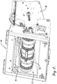
FIG. 2 is a perspective view of a feeder box of the combine harvester shown inFIG. 1 and including an organic material throughput sensor according to aspects of the invention; -
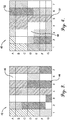
FIG. 3 is a yield map compiled using data sensed by a yield sensor of the combine harvester shown inFIG. 1 ; -
FIG. 4 is an organic material throughput map compiled using data sensed by an organic material throughput sensor of the combine harvester shown inFIG. 1 ; -
FIG. 5 is a flowchart schematically representing a method of making a planting or treatment decision using organic material throughput data sensed by the organic material throughput sensor of the combine harvester shown inFIG. 1 ; -
FIG. 6 is a flowchart schematically representing a method of making a planting or treatment decision using organic material throughput data sensed over time by the organic material throughput sensor of the combine harvester shown inFIG. 1 ; -
FIG. 7 is a flowchart schematically representing a method of making a planting or treatment decision using organic material throughput data for two or more crops or crop varietals sensed by the organic material throughput sensor of the combine harvester shown inFIG. 1 ; and -
FIG. 8 is a flowchart schematically representing a method of making a planting or treatment decision using organic material throughput data and yield data sensed by the organic material throughput sensor and yield sensor, respectively, of the combine harvester shown inFIG. 1 . - Generally, aspects of the invention are directed to a methods and systems for collecting organic material throughput data and using the same instead of, or else in addition to, other data such as crop yield data when making a planting or treatment decision. More particularly, the invention is directed to measuring the total relative harvested crop volume, which correlates to the overall spread organic matter in the field, and making a planting or treatment decision in light of the same.
- In some embodiments, a producer, grower, or other user can use the organic material throughput data to, for example, build maps relating organic soil health directly to harvested organic volume and thus a prescription map can be compiled for adding organic material to the areas lacking. Moreover, crop yield and crop volume do not always correlate. The mapped organic material throughput data thus provides a producer the ability to determine crop varieties efficiencies based on yield, fertilizer consumption, and total plant mass. Still more, crop residue is often removed from the field by several different methods including bailing, burning, and grazing, among others. This removed material results in the reduction of the number of micro- and macro-nutrients in the soil. Using the organic material throughput data, the producer can replace these nutrients as required without the using a soil map. And using the organic material throughput data gives the producer the ability to map organic matter over time, which can be applied to future soil health goals. These and other aspects of the invention will become more apparent via the detailed description of the invention in connection with the accompanying figures.
-
FIG. 1 shows acombine harvester 10 that may employ various aspects of the invention. Thecombine harvester 10 generally includes amain body 12 housing various crop threshing, cleaning, transporting, and storage equipment as will be discussed in more detail below. Themain body 12 supports front drive wheels ortracks 14,rear steering wheels 16, and an operator'scab 34 at a front portion of thecombine harvester 10. Extending from a front of themain body 12 is afeeder house 18 operatively coupled to acrop gathering header 20. As will be discussed in more detail, thefeeder house 18 feeds cut organic material into an interior of themain body 12 during operation of thecombine harvester 10, while thecrop gathering header 20 gathers, cuts, and conveys the organic material to thefeeder house 18. - More particularly, the
crop gathering header 20 includes various cutting and transporting mechanisms used to sever the organic material from a field and direct the organic material towards thefeeder house 18. For example, in the depicted embodiment thecrop gathering header 20 includes areel 22 andauger 24. As thecombine harvester 10 moves forward (via operation of the front drive wheels or tracks 14), thereel 22 rotates and severs the crop being harvested from the field. Thespinning auger 24 then transports the cut organic material towards a center of thecombine harvester 10, and more particularly towards an opening 25 in the rear wall of thecrop gathering header 20 that is aligned with an open inlet 37 of theouter casing 36 of the feeder house 18 (FIG. 2 ). Thefeeder house 18 in turn conveys the organic material into an interior of themain body 12 via anelevator 38. More particularly, the rotatingelevator 38 engages the cut organic material and transports it generally upwards and backwards, towards an open outlet of theouter casing 36 of thefeeder house 18. - Once inside the
main body 12, the cut organic material is first fed to athreshing mechanism 26. At a high level, thethreshing mechanism 26 includes various cylinders, concaves, separators, pans, sieves, cleaners, and other mechanisms for separating grain or other harvested crop from the straw, chaff, and other byproducts of the cut organic material. The separated grain or harvested crop is then carried via an elevator or the like to a grain tank 28 in themain body 12, while the straw, chaff, and other byproducts are exhausted from a back end of thecombine harvester 10 to be later baled or otherwise removed from the field, or else stored in astraw tank 30 for later removal. Once the grain tank 28 is at or near capacity, the grain is unloaded into a trailer or cart via theunloading tube 32. - In some embodiments, the
combine harvester 10 may include ayield sensor 27 to monitor the yield of the crop being harvested. Theyield sensor 27 may be, for example, an optical or weight sensor that measures the amount of grain or the like being transported to the grain tank 28 as thecombine harvester 10 operates. This yield data can then be relayed in real-time to an operator within the operator'scab 34 so that the operator knows when the grain tank 28 needs to be emptied. Or the yield data may be stored via an on-board memory for later uploading to a data management system such as a Farm Management Information System (FMIS) or other suitable program, or else transmitted wirelessly by a wireless communication system on the combine harvester to the data management or similar system. - The data management or similar system in turn is configured to output the data in tabular format, in a map format, or in another desired format for an end-user to review and make planting or treatment decisions in light of the same. For example,
FIG. 3 depicts ayield map 42 graphically depicting the yield from a plurality of zones of a harvested field as one example of a yield map that may be generated by the data management or similar system. In the depicted embodiment, theyield map 42 uses different density cross-hatching to graphically represent the yield harvested. Thus, in some embodiments zones without cross-hatching or with relatively little cross hatching, such aszone 46 located at A-6 of theyield map 42's grid, yielded a relatively low amount of crop, while zones with relatively dense cross-hatching, such aszone 44 located at G-5 of theyield map 42's grid, yielded a relatively large amount of crop. Farm operators can in turn use the yield map or similar data to make appropriate decisions regarding fertilizer application, soil conditioning, and other decisions to ensure a more productive crop in future plantings. - In addition to or instead of the
yield sensor 27, embodiments of the invention include an organicmaterial throughput sensor 40 that senses a total throughput of organic material passing through thecombine harvester 10. Unlike theyield sensor 27, which only measures a mass, weight, volume, or other metric of the grain or harvested crop, the organicmaterial throughput sensor 40 measures a mass, weight, volume, or other metric of the total organic material cut and removed from the field being harvested. This data can then be used in addition to, or in some instances in combination with, theyield sensor 27 data to make more informed decisions about fertilization, soil conditioning, and others as will be described in more detail below. As with the yield data, in some embodiments the organic material throughput data can be provided to an operator in real-time such as via a user interface within thecab 34 of thecombine harvester 10. - As shown in
FIG. 2 , in some embodiments the organicmaterial throughput sensor 40 is provided in thefeeder house 18 of thecombine harvester 10. The organicmaterial throughput sensor 40 can be any desired type of sensor capable of detecting a volume, mass, weight, or other desired metric of the organic material passing through thefeeder house 18. For example, in some embodiments the organicmaterial throughput sensor 40 may be an optical sensor that visually detects a volume of the organic material passing thereby. In other embodiments, the organicmaterial throughput sensor 40 may be a weight sensor operatively coupled to thefeeder house 18elevator 38 that detects a weight of the material being transported by theelevator 38. Other types of sensors can be implemented without departing from the scope of the invention. - As with the data from the
yield sensor 27, the data logged by the organicmaterial throughput sensor 40 can be provided to an operator in real time, can be stored on-board via a memory device or the like, and/or can be transmitted or uploaded to a data management system (e.g., FMIS software package or other program) for analysis. In some embodiments, using the organic material throughput data that data management system generates an organicmaterial throughput map 48 such as that shown inFIG. 4 . More particularly,FIG. 4 depicts an organicmaterial throughput map 48 that graphically depicts the total organic material removed from a plurality of zones of a harvested field as one example of an organic material throughput map that may be generated by the data management system. In the depicted embodiment, the organicmaterial throughput map 48 cross-hatches different zones according to the amount of organic material removed from the field at the corresponding location. Thus, in some embodiments, in white zones or zones with relatively low amounts of cross-hatching, such aszone 49 located at D-3 of themap 48's grid, a relatively low amount of organic material was removed from the field, while in zones including relatively dense cross hatching, such aszone 52 located at A-6 of themap 48's grid, a relatively large amount of organic material was removed from the field. - The data provided by the organic
material throughput map 48 provides producers and other growers with a more complete view of the health of a given field or crop, which in turn aids the producer in making future fertilization, soil conditioning, and other decisions. More particularly, by having access to the organicmaterial throughput map 48 in addition to theyield map 42, the producer has more complete agronomic data showing the health of a field or the condition of the soil. This is particularly useful because there is not always a correlation between yield and total crop mass, as both crop mass and yield may vary throughout the field, independent of each other. Capturing the total crop material throughput provides an additional data set for use by the producer to make future decisions. - For example,
FIGS. 5-8 are flowcharts schematically representing methods of using crop data such as data logged by the organicmaterial throughput sensor 40 according to some embodiments of the invention. First,FIG. 5 is a flowchart schematically representing amethod 54 of making a planting decision or a treatment decision based on the organic material throughput data. For example, in some embodiments a producer may wish to apply an amount of fertilizer to a field proportional to the amount of total organic material removed from the field. Thus, by using (at least in part) logged data regarding the total organic material throughput removed from a field during harvest, a producer can make an informed decision regarding how much fertilizer to thereafter add to a field. - Turning to the
method 54, at step 56 a producer or other operator cuts a crop in a field using a combine harvester, such as thecombine harvester 10 described in connection withFIG. 1 . Atstep 58, the cut crop is conveyed to a central portion of thecrop gathering header 20, proximate anopening 25 in the rear wall of thecrop gathering header 20. Atstep 60, the cut crop is then conveyed through thefeeder box 18, and more particularly through an open inlet 37 of the outer casing of thefeeder box 18, through an interior of thefeeder box 18, and then through an open outlet of theouter casing 36 for later conveying through various stages of thecombine harvester 10 including athreshing mechanism 26. - At
step 62, while the organic material is being conveyed through thefeeder box 18 and prior to being passed through the threshingmechanism 26, the organic material throughput is sensed using any desired sensor such as an optical, weight, ormass sensor 40. The data from the sensor is stored in any desired format via on on-board memory device or the like or else is transmitted wirelessly for storage at a remote location such as a centralized server, personal computer, or similar device having a suitable memory device. Atstep 64, the data from the sensor is uploaded into a data management system such as a FMIS software package or the like for review by a producer. In some embodiments the software package may output the data graphically in the form of an organic mass throughput map such as themap 48 discussed in connection withFIG. 4 . - At
step 66 the producer makes at least one of a planting and treatment decision based on its review of the data. In some embodiments, the planting and/or treatment decision may be one of which type of crop and/or varietal to plant, or may be what type and/or quantity of fertilizer to apply to the field. For example, the producer may determine how much total fertilizer should be applied the harvested field based on the total amount of organic material removed from the filed during the harvesting. Or the producer may determine where to selectively apply fertilizer in the field according to the data. As one example, a producer may desire to apply more fertilizer in areas of the field where the most organic material was removed during harvesting. In such embodiments, atstep 66 the producer may thus decide to apply more fertilizer to areas where there was a relatively large volume of organic material remove-such aszone 52 in the organic mass throughput map 48-and apply less fertilizer to areas where there was a relatively low volume of organic material removed-such aszone 49 in the organicmass throughput map 48. - In some embodiments, the producer may make a planting, treatment, or other decision based on material throughput data over time. This may replace or else augment the need to take soil samples of a field, which are traditionally used to make fertilizer and other treatment decisions. More particularly,
FIG. 6 is a flowchart schematically representing amethod 68 of determining how much or what type of fertilizer to apply to a field using material throughput data over time. Atsteps method 68, a producer cuts a crop, conveys it to and through a feeder box of a combine harvester, senses the organic material throughput with a sensor in the feeder box, and uploads the sensor data to a software package or the like in a similar manner as described about with respect tosteps method 54, which thus will not be repeated in detail. - In order to view material throughput data of a particular field or the like over time, steps 70, 72, 74, 76, and 78 are repeated such that the producer has data for two or more successive harvests. Namely, at
step 80, when more data is to be collected for a time lapse comparison, steps 70, 72, 74, 76, and 78 are repeated for a successive harvest. Once enough data has been collected for a time-lapse comparison-i.e., once data has been collected for two or more harvests-the method proceeds to step 82, where a data management system generates material throughput maps or other time-lapse data detailing the organic material throughput over time. - At step 84 a producer makes a planting or treatment decision based on the data outputted at
step 82. For example, in some embodiments the producer determines an amount or type of fertilizer to apply to a field based on the data outputted atstep 82. In such embodiments, the producer may decide to apply a first type and/or amount of fertilizer if the data shows a steadily decreasing material throughput from a particular field over time. Or the producer may decide to apply a second type and/or amount of fertilizer if the data shows a steadily increasing material throughput from a particular field over time. Still more, the producer may decide to apply a third type and/or amount of fertilizer if the data shows a relatively steady material throughput from a particular field over time. By utilizing the time lapse data in such a fashion, the producer may be able to replace, or else augment, soil sampling traditionally carried out to make such fertilization decisions. - In some embodiments, the producer may make a planting decision based on a comparison of material throughput data for a plurality of crops and/or varietals of crops. More particularly,
FIG. 7 is a flowchart schematically representing amethod 86 of determining which crop or crop varietal using organic material throughput data. Atsteps method 86, a producer cuts a crop, conveys it to and through a feeder box of a combine harvester, senses the organic material throughput with a sensor in the feeder box, and uploads the sensor data to a data management system such as FMIS software or the like in a similar manner as described about with respect tosteps method 54, which thus will not be described again in detail. - In order to compare material throughput data for two or more crops or crop varietals, steps 88, 90, 92, 94, and 96 of
method 86 are repeated such that the producer has data for two or more crops and/or crop varietals. Namely, atstep 98, when more data is to be collected for crop or varietal comparison, steps 88, 90, 92, 94, and 96 are repeated for a different crop and/or crop varietal. For example, data may be collected for a different field in which a different crop or crop varietal was planted, or data may be collected in a successive harvest for the same field but for which a different crop or crop varietal was planted. - Once enough data has been collected for a crop or crop varietal comparison-i.e., once data has been collected for two or more crops or crop varietals-the method proceeds to step 100, where the data management system generates material throughput maps or other graphical output detailing the data collected from the material throughput sensor. For example, in some embodiments at least two different organic material throughput maps-similar to the
map 48 shown inFIG. 4 -are generated, one for each crop and/or crop varietal being compared. The producer or other user is then able to quickly visualize and compare the performance of each crop and/or crop varietal. For example, in some embodiments a first set of data is collected for a first wheat hybrid and a second set of data is collected for a second wheat hybrid. In such embodiments, a producer may compare, among other data, the organic material throughput map for the first wheat hybrid with the organic material throughput map for the second wheat hybrid. This data may provide the producer a more useful side-by-side comparison of crop hybrids than known comparisons. More particularly, instead of just comparing yield, this data enables producers to compare total plant mass for each varietal. - In still other embodiments, the producer may make a crop planting and/or treatment decision based on both sensed yield and total organic material throughput. This may be more readily understood with reference to
FIG. 8 . More particularly,FIG. 8 is a flowchart schematically representing amethod 104 of making a planting or treatment decision based on at least two different metrics for a single crop; in this case, total organic material and crop yield. Atsteps method 104, a producer cuts a crop, conveys it to and through a feeder box of a combine harvester, and senses the organic material throughput with a sensor in the feeder box in a similar manner as described above with respect tosteps method 54, which thus will not be described again in detail. Atstep 114, the cut material is then conveyed through a threshing and/or cleaning mechanism, such as the threshingmechanism 26 described in connection with thecombine harvester 10. Again, the threshing and/or cleaning mechanism separates the harvested crop (e.g., grain) from the byproducts (e.g., straw, chaff, etc.). Atstep 118, a yield sensor such asyield sensor 27 discussed above in connection withcombine harvester 10 senses the yield of the harvested crop. - At
step 120, the data from the organic material throughput sensor and yield sensor is uploaded to the data management system such as the FMIS software discussed above. And finally, atstep 122, a producer or the like makes one of a planting and/or a treatment decision based at least in part on data from the organic material throughput sensor and the yield sensor. For example, in some embodiments the data management system may output the yield data and the organic material throughput data in the form of a yield map (similar to that shown inFIG. 3 ) and an organic material throughput map (similar to that shown inFIG. 4 ). In turn, the producer makes one of a planting decision and a treatment decision based at least in part on the yield map and the organic material throughput map. For example, if the comparison reveals that the total organic material cut for a certain field is relatively high, but the overall yield is relatively low, the producer may thereafter plant a different crop varietal and/or apply a different amount or type of fertilizer in an effort to improve yield in subsequent harvests. In short, the two sets of data provide a more complete set of data to the producer in order to make more informed planting and/or treatment decisions. - From the foregoing, it will be seen that this invention is one well adapted to attain all the ends and objects hereinabove set forth together with other advantages which are obvious and which are inherent to the structure. It will be understood that certain features and subcombinations are of utility and may be employed without reference to other features and subcombinations. This is contemplated by and is within the scope of the claims. Since many possible embodiments may be made of the invention without departing from the scope thereof, it is to be understood that all matter herein set forth or shown in the accompanying drawings is to be interpreted as illustrative and not in a limiting sense. Additional objects, advantages, and novel features of the invention will be apparent to those skilled in the art upon examination of the above or may be learned by practice of the invention.
Claims (20)
- A method of monitoring a throughput of a crop, the method comprising:cutting organic material using a combine harvester;conveying the organic material through the combine harvester to a threshing mechanism located within a main body of the combine harvester;sensing, prior to the organic material being conveyed through the threshing mechanism and using an organic material throughput sensor, organic material throughput data, wherein the organic material throughput data comprises at least one of: a volume of the organic material, and a weight of the organic material;transmitting the organic material throughput data to a data management system; andoutputting, by the data management system, an organic material throughput map based on the organic material throughput data.
- The method of claim 1 further comprising determining, based on the organic material throughput data, at least one of: a type of crop to plant in a field, and an amount of seed to plant in the field.
- The method of claim 1 further comprising determining, based on the organic material throughput data, at least one of: a type of fertilizer to apply to a field, and an amount of fertilizer to apply to the field.
- The method of claim 1, wherein the combine harvester includes a feeder box configured to convey the organic material from a header of the combine harvester to the main body of the combine harvester, and wherein the organic material throughput sensor is provided in the feeder box.
- The method of claim 1 further comprising:separating, via the threshing mechanism, a harvestable crop from byproducts of the organic material;sensing, using a yield sensor within the combine harvester, yield data, wherein the yield data comprises at least one of: a volume of the harvestable crop, and a weight of the harvestable crop;transmitting the yield data to the data management system; andoutputting, by the data management system, a yield map based on the yield data.
- The method of claim 5 further comprising determining, based on a comparison of the organic material throughput data and the yield data, at least one of: a type of crop to plant in a field, and an amount of seed to plant in the field.
- The method of claim 5 further comprising determining, based on a comparison of the organic material throughput data and the yield data, at least one of: a type of fertilizer to apply to a field, and an amount of fertilizer to apply to the field.
- A method of monitoring a throughput of a crop, the method comprising:cutting a first set of organic material using a combine harvester;conveying the first set of organic material through the combine harvester to a threshing mechanism located within a main body of the combine harvester;sensing, prior to the first set of organic material being conveyed through the threshing mechanism and using an organic material throughput sensor, a first organic material throughput data, wherein the first organic material throughput data comprises at least one of: a volume of the first set of organic material, and a weight of the first set of organic material;cutting a second set of organic material using the combine harvester;conveying the second set of organic material through the combine harvester to the threshing mechanism;sensing, prior to the second set of organic material being conveyed through the threshing mechanism and using the organic material throughput sensor, second organic material throughput data, wherein the second organic material throughput data comprises at least one of: a volume of the second set of organic material, and a weight of the second set of organic material; anddetermining, based on a comparison of the first organic material throughput data and the second organic material throughput data, at least one of: a type of crop to plant in a field, an amount of seed to plant in the field, a type of fertilizer to apply to the field, and an amount of fertilizer to apply to the field.
- The method of claim 8, further comprising:transmitting the first and second organic material throughput data to a data management system; andoutputting, by the data management system, a first and second organic material throughput map based on the first and second organic material throughput data, respectively.
- The method of claim 8, wherein the combine harvester includes a feeder box configured to convey the organic material from a header of the combine harvester to the main body of the combine harvester, and wherein the organic material throughput sensor is provided in the feeder box.
- The method claim 8, wherein the first set of organic material comprises a first crop varietal, and wherein the second set of organic material comprises a second crop varietal different from the first crop varietal.
- The method claim 8, wherein the first set and second set of organic material are cut from a field, wherein the first set of organic material is cut from a field during a first harvest, and wherein the second set of organic material is cut from a field during a second harvest.
- The method of claim 12 further comprising planting a crop in the field between the first harvest and the second harvest.
- A system for monitoring a throughput of a crop, the system comprising:a combine harvester comprising:a feeder box;a main body downstream of the feeder box;a threshing mechanism within the main body; andan organic material throughput sensor provided within the feeder box; and a data management system remote from the combine harvester,wherein the organic material throughput sensor is configured to sense organic material throughput data comprising at least one of: a volume of the organic material, and a weight of the organic material; andwherein the data management system is configured to output an organic material throughput map based on the organic material throughput data.
- The system of claim 14, wherein the combine harvester further comprises a crop gathering header upstream of the feeder box, and wherein the crop gathering header is configured to cut organic material from a field and convey the organic material to the feeder box.
- The system of claim 14 further comprising:a yield sensor provided within the main body and downstream of the threshing mechanism,wherein the threshing mechanism is configured to separate the organic material into a harvestable crop and byproducts, andwherein the yield sensor is configured to sense yield data comprising at least one of: a volume of the harvestable crop, and a weight of the harvestable crop.
- The system of claim 16, wherein the data management system is further configured to output a yield map based on the yield data.
- The system of claim 16, wherein the combine harvester includes a cab, and wherein the combine harvester is configured to output at least one of the organic material throughput data and the yield data to a user interface within the cab in real-time.
- The system of claim 14, wherein the combine harvester further comprises a memory configured to store the organic material throughput data.
- The system of claim 14, wherein the combine harvester further comprises a wireless communication system, and wherein the wireless communication system is configured to transmit the organic material throughput data to the data management system.
Applications Claiming Priority (1)
| Application Number | Priority Date | Filing Date | Title |
|---|---|---|---|
| US201962954740P | 2019-12-30 | 2019-12-30 |
Publications (2)
| Publication Number | Publication Date |
|---|---|
| EP3845050A1 true EP3845050A1 (en) | 2021-07-07 |
| EP3845050B1 EP3845050B1 (en) | 2023-11-29 |
Family
ID=71950491
Family Applications (1)
| Application Number | Title | Priority Date | Filing Date |
|---|---|---|---|
| EP20189573.7A Active EP3845050B1 (en) | 2019-12-30 | 2020-08-05 | Methods and systems for measuring organic material throughput data of harvested crops |
Country Status (2)
| Country | Link |
|---|---|
| US (1) | US11874148B2 (en) |
| EP (1) | EP3845050B1 (en) |
Cited By (5)
| Publication number | Priority date | Publication date | Assignee | Title |
|---|---|---|---|---|
| EP4205529A1 (en) * | 2022-01-04 | 2023-07-05 | CNH Industrial Belgium N.V. | Feed rate sensor for a combine harvester |
| US12310285B2 (en) | 2023-02-27 | 2025-05-27 | Deere & Company | Agricultural operation evaluation system and method |
| US12457934B2 (en) | 2023-01-09 | 2025-11-04 | Deere & Company | Residue sensing and cleaning system |
| US12464979B2 (en) | 2023-11-09 | 2025-11-11 | Deere & Company | Residue spread control |
| US12550819B2 (en) | 2023-04-12 | 2026-02-17 | Deere & Company | Residue sensor protection on a harvester |
Families Citing this family (1)
| Publication number | Priority date | Publication date | Assignee | Title |
|---|---|---|---|---|
| CN115152410B (en) * | 2022-08-15 | 2023-05-09 | 四川农业大学 | A multifunctional combined real-time corn yield measurement device and method |
Citations (7)
| Publication number | Priority date | Publication date | Assignee | Title |
|---|---|---|---|---|
| DE3232746A1 (en) * | 1982-09-03 | 1984-03-08 | Gerhard Dipl.-Ing. 4930 Detmold Römer | Mobile cereal harvester, such as baling press and loading truck with collecting device (pick-up) or combine harvester |
| EP0958729A1 (en) * | 1998-05-22 | 1999-11-24 | New Holland Belgium N.V. | Harvester with crop flow rate sensor |
| JP2000354416A (en) * | 1999-06-16 | 2000-12-26 | Yanmar Agricult Equip Co Ltd | Combine yield detector |
| WO2002041687A2 (en) * | 2000-11-24 | 2002-05-30 | Cnh Belgium N.V. | A method of estimating crop yields |
| EP2944179A1 (en) * | 2014-05-16 | 2015-11-18 | Deere & Company | Multi-sensor crop yield determination |
| US20170112061A1 (en) * | 2015-10-27 | 2017-04-27 | Cnh Industrial America Llc | Graphical yield monitor static (previous) data display on in-cab display |
| WO2018092718A1 (en) * | 2016-11-15 | 2018-05-24 | ヤンマー株式会社 | Yield distribution calculation device and yield distribution calculation method |
Family Cites Families (21)
| Publication number | Priority date | Publication date | Assignee | Title |
|---|---|---|---|---|
| GB9811177D0 (en) * | 1998-05-26 | 1998-07-22 | Ford New Holland Nv | Methods for generating field maps |
| US6073427A (en) * | 1998-06-11 | 2000-06-13 | Nichols; Stephen W. | Method and apparatus for counting crops |
| DE102013106131A1 (en) * | 2012-07-16 | 2014-06-12 | Claas Selbstfahrende Erntemaschinen Gmbh | Driver assistance system for agricultural machine |
| US11212962B2 (en) * | 2013-02-20 | 2022-01-04 | Deere & Company | Field condition determination |
| US9668420B2 (en) * | 2013-02-20 | 2017-06-06 | Deere & Company | Crop sensing display |
| EP2910098B1 (en) * | 2014-02-20 | 2018-10-17 | CLAAS E-Systems KGaA mbH & Co KG | Agricultural machine and method for controlling a working device |
| DE102014102789A1 (en) * | 2014-03-03 | 2015-09-03 | Claas Selbstfahrende Erntemaschinen Gmbh | Agricultural working machine |
| WO2015160837A2 (en) * | 2014-04-15 | 2015-10-22 | Raven Industries, Inc. | Reaping based yield monitoring system and method for the same |
| US10034423B2 (en) * | 2014-07-29 | 2018-07-31 | Deere & Company | Biomass sensing |
| EP3000304B1 (en) * | 2014-09-23 | 2018-09-26 | Deere & Company | Aggregate yield allocation |
| US10126282B2 (en) * | 2014-09-23 | 2018-11-13 | Deere & Company | Yield estimation |
| US9903979B2 (en) | 2014-09-23 | 2018-02-27 | Deere & Company | Yield estimation |
| US10188037B2 (en) * | 2015-09-24 | 2019-01-29 | Deere & Company | Yield estimation |
| CN110602942B (en) * | 2017-06-26 | 2022-08-19 | 株式会社久保田 | Harvesting machine |
| BR112020004630A2 (en) * | 2017-09-11 | 2020-09-24 | Farmers Edge Inc. | generation of a yield map for an agricultural field using regression and classification methods |
| DE102018103373A1 (en) * | 2018-02-15 | 2019-08-22 | Claas Selbstfahrende Erntemaschinen Gmbh | Combine harvester and method for its operation |
| DE102018111077A1 (en) * | 2018-05-08 | 2019-11-14 | Claas Selbstfahrende Erntemaschinen Gmbh | Combine harvester and method for operating a combine harvester |
| DE102018111076A1 (en) * | 2018-05-08 | 2019-11-14 | Claas Selbstfahrende Erntemaschinen Gmbh | Harvester |
| US10820516B2 (en) | 2018-05-08 | 2020-11-03 | Cnh Industrial America Llc | System and method for monitoring the amount of plant materials entering an agricultural harvester |
| US10820504B2 (en) * | 2018-07-03 | 2020-11-03 | Cnh Industrial America Llc | System and method for determining the residue yield of plant materials harvested by an agricultural harvester |
| DE102019121052A1 (en) * | 2019-08-05 | 2021-02-11 | Claas Selbstfahrende Erntemaschinen Gmbh | Yield mapping method |
-
2020
- 2020-08-05 EP EP20189573.7A patent/EP3845050B1/en active Active
- 2020-12-30 US US17/138,514 patent/US11874148B2/en active Active
Patent Citations (7)
| Publication number | Priority date | Publication date | Assignee | Title |
|---|---|---|---|---|
| DE3232746A1 (en) * | 1982-09-03 | 1984-03-08 | Gerhard Dipl.-Ing. 4930 Detmold Römer | Mobile cereal harvester, such as baling press and loading truck with collecting device (pick-up) or combine harvester |
| EP0958729A1 (en) * | 1998-05-22 | 1999-11-24 | New Holland Belgium N.V. | Harvester with crop flow rate sensor |
| JP2000354416A (en) * | 1999-06-16 | 2000-12-26 | Yanmar Agricult Equip Co Ltd | Combine yield detector |
| WO2002041687A2 (en) * | 2000-11-24 | 2002-05-30 | Cnh Belgium N.V. | A method of estimating crop yields |
| EP2944179A1 (en) * | 2014-05-16 | 2015-11-18 | Deere & Company | Multi-sensor crop yield determination |
| US20170112061A1 (en) * | 2015-10-27 | 2017-04-27 | Cnh Industrial America Llc | Graphical yield monitor static (previous) data display on in-cab display |
| WO2018092718A1 (en) * | 2016-11-15 | 2018-05-24 | ヤンマー株式会社 | Yield distribution calculation device and yield distribution calculation method |
Cited By (5)
| Publication number | Priority date | Publication date | Assignee | Title |
|---|---|---|---|---|
| EP4205529A1 (en) * | 2022-01-04 | 2023-07-05 | CNH Industrial Belgium N.V. | Feed rate sensor for a combine harvester |
| US12457934B2 (en) | 2023-01-09 | 2025-11-04 | Deere & Company | Residue sensing and cleaning system |
| US12310285B2 (en) | 2023-02-27 | 2025-05-27 | Deere & Company | Agricultural operation evaluation system and method |
| US12550819B2 (en) | 2023-04-12 | 2026-02-17 | Deere & Company | Residue sensor protection on a harvester |
| US12464979B2 (en) | 2023-11-09 | 2025-11-11 | Deere & Company | Residue spread control |
Also Published As
| Publication number | Publication date |
|---|---|
| US11874148B2 (en) | 2024-01-16 |
| US20210195839A1 (en) | 2021-07-01 |
| EP3845050B1 (en) | 2023-11-29 |
Similar Documents
| Publication | Publication Date | Title |
|---|---|---|
| US11874148B2 (en) | Methods and systems for measuring organic material throughput data of harvested crops | |
| US11419261B2 (en) | Prescription cover crop seeding with combine | |
| JP6444491B2 (en) | Combine and grain evaluation control device for combine | |
| US20210084806A1 (en) | Method for operating a harvesting machine with the aid of a plant growth model | |
| US10408645B2 (en) | Correcting bias in parameter monitoring | |
| US8177610B2 (en) | Combination residue spreader and collector for single pass harvesting systems | |
| US20190110394A1 (en) | Crop yield and obstruction detection system for a harvesting header | |
| US20170112061A1 (en) | Graphical yield monitor static (previous) data display on in-cab display | |
| US20160029558A1 (en) | Biomass sensing | |
| US20120245802A1 (en) | Crop Residue Spreading | |
| CA2644959A1 (en) | Separating cobs from grain in a corn harvester | |
| EP1349443A2 (en) | A method of estimating crop yields | |
| US11744182B2 (en) | Crop yield determining apparatus | |
| US20250143283A1 (en) | Field prediction for agricultural harvesters | |
| Wang et al. | A review of key technologies and intelligent applications in soybean mechanized harvesting: Chinese and international perspectives | |
| JP7321088B2 (en) | work vehicle | |
| Boydell et al. | Deconvolution of site-specific yield measurements to address peanut combine dynamics | |
| US20240138296A1 (en) | System and method for determining crop population within a field during a harvesting operation being performed by an agricultural harvester | |
| Chandel et al. | Performance Analysis of a Combine Harvester for Wheat Crop in Lodged Conditions for India | |
| US20220210976A1 (en) | Greenhouse Harvester of Cannabis | |
| Singh et al. | Grain losses in combine harvesting of paddy | |
| WO2025219787A1 (en) | Methods and systems for generating fertilizer prescription maps | |
| BR102023022792A2 (en) | AGRICULTURAL HARVEST, SYSTEM AND METHOD FOR DETERMINING CROP POPULATION WITHIN A FIELD DURING A HARVEST OPERATION | |
| US20200008353A1 (en) | Greenhouse harvester of cannabis | |
| BR102019007883B1 (en) | WORKING MACHINE, SYSTEM FOR PLANTING A COVERAGE PLANT DURING A HARVESTING OPERATION, METHOD FOR ACTIVELY MANAGING AND DISTRIBUTING A COVERAGE PLANT SEED |
Legal Events
| Date | Code | Title | Description |
|---|---|---|---|
| PUAI | Public reference made under article 153(3) epc to a published international application that has entered the european phase |
Free format text: ORIGINAL CODE: 0009012 |
|
| STAA | Information on the status of an ep patent application or granted ep patent |
Free format text: STATUS: THE APPLICATION HAS BEEN PUBLISHED |
|
| AK | Designated contracting states |
Kind code of ref document: A1 Designated state(s): AL AT BE BG CH CY CZ DE DK EE ES FI FR GB GR HR HU IE IS IT LI LT LU LV MC MK MT NL NO PL PT RO RS SE SI SK SM TR |
|
| STAA | Information on the status of an ep patent application or granted ep patent |
Free format text: STATUS: REQUEST FOR EXAMINATION WAS MADE |
|
| 17P | Request for examination filed |
Effective date: 20220107 |
|
| RBV | Designated contracting states (corrected) |
Designated state(s): AL AT BE BG CH CY CZ DE DK EE ES FI FR GB GR HR HU IE IS IT LI LT LU LV MC MK MT NL NO PL PT RO RS SE SI SK SM TR |
|
| P01 | Opt-out of the competence of the unified patent court (upc) registered |
Effective date: 20230518 |
|
| GRAP | Despatch of communication of intention to grant a patent |
Free format text: ORIGINAL CODE: EPIDOSNIGR1 |
|
| STAA | Information on the status of an ep patent application or granted ep patent |
Free format text: STATUS: GRANT OF PATENT IS INTENDED |
|
| GRAS | Grant fee paid |
Free format text: ORIGINAL CODE: EPIDOSNIGR3 |
|
| INTG | Intention to grant announced |
Effective date: 20230928 |
|
| GRAA | (expected) grant |
Free format text: ORIGINAL CODE: 0009210 |
|
| STAA | Information on the status of an ep patent application or granted ep patent |
Free format text: STATUS: THE PATENT HAS BEEN GRANTED |
|
| AK | Designated contracting states |
Kind code of ref document: B1 Designated state(s): AL AT BE BG CH CY CZ DE DK EE ES FI FR GB GR HR HU IE IS IT LI LT LU LV MC MK MT NL NO PL PT RO RS SE SI SK SM TR |
|
| REG | Reference to a national code |
Ref country code: GB Ref legal event code: FG4D |
|
| REG | Reference to a national code |
Ref country code: CH Ref legal event code: EP |
|
| REG | Reference to a national code |
Ref country code: DE Ref legal event code: R096 Ref document number: 602020021765 Country of ref document: DE |
|
| REG | Reference to a national code |
Ref country code: IE Ref legal event code: FG4D |
|
| REG | Reference to a national code |
Ref country code: LT Ref legal event code: MG9D |
|
| REG | Reference to a national code |
Ref country code: NL Ref legal event code: MP Effective date: 20231129 |
|
| PG25 | Lapsed in a contracting state [announced via postgrant information from national office to epo] |
Ref country code: GR Free format text: LAPSE BECAUSE OF FAILURE TO SUBMIT A TRANSLATION OF THE DESCRIPTION OR TO PAY THE FEE WITHIN THE PRESCRIBED TIME-LIMIT Effective date: 20240301 |
|
| PG25 | Lapsed in a contracting state [announced via postgrant information from national office to epo] |
Ref country code: IS Free format text: LAPSE BECAUSE OF FAILURE TO SUBMIT A TRANSLATION OF THE DESCRIPTION OR TO PAY THE FEE WITHIN THE PRESCRIBED TIME-LIMIT Effective date: 20240329 |
|
| PG25 | Lapsed in a contracting state [announced via postgrant information from national office to epo] |
Ref country code: LT Free format text: LAPSE BECAUSE OF FAILURE TO SUBMIT A TRANSLATION OF THE DESCRIPTION OR TO PAY THE FEE WITHIN THE PRESCRIBED TIME-LIMIT Effective date: 20231129 |
|
| PG25 | Lapsed in a contracting state [announced via postgrant information from national office to epo] |
Ref country code: ES Free format text: LAPSE BECAUSE OF FAILURE TO SUBMIT A TRANSLATION OF THE DESCRIPTION OR TO PAY THE FEE WITHIN THE PRESCRIBED TIME-LIMIT Effective date: 20231129 |
|
| PG25 | Lapsed in a contracting state [announced via postgrant information from national office to epo] |
Ref country code: LT Free format text: LAPSE BECAUSE OF FAILURE TO SUBMIT A TRANSLATION OF THE DESCRIPTION OR TO PAY THE FEE WITHIN THE PRESCRIBED TIME-LIMIT Effective date: 20231129 Ref country code: IS Free format text: LAPSE BECAUSE OF FAILURE TO SUBMIT A TRANSLATION OF THE DESCRIPTION OR TO PAY THE FEE WITHIN THE PRESCRIBED TIME-LIMIT Effective date: 20240329 Ref country code: GR Free format text: LAPSE BECAUSE OF FAILURE TO SUBMIT A TRANSLATION OF THE DESCRIPTION OR TO PAY THE FEE WITHIN THE PRESCRIBED TIME-LIMIT Effective date: 20240301 Ref country code: ES Free format text: LAPSE BECAUSE OF FAILURE TO SUBMIT A TRANSLATION OF THE DESCRIPTION OR TO PAY THE FEE WITHIN THE PRESCRIBED TIME-LIMIT Effective date: 20231129 Ref country code: BG Free format text: LAPSE BECAUSE OF FAILURE TO SUBMIT A TRANSLATION OF THE DESCRIPTION OR TO PAY THE FEE WITHIN THE PRESCRIBED TIME-LIMIT Effective date: 20240229 |
|
| REG | Reference to a national code |
Ref country code: AT Ref legal event code: MK05 Ref document number: 1635100 Country of ref document: AT Kind code of ref document: T Effective date: 20231129 |
|
| PG25 | Lapsed in a contracting state [announced via postgrant information from national office to epo] |
Ref country code: NL Free format text: LAPSE BECAUSE OF FAILURE TO SUBMIT A TRANSLATION OF THE DESCRIPTION OR TO PAY THE FEE WITHIN THE PRESCRIBED TIME-LIMIT Effective date: 20231129 |
|
| PG25 | Lapsed in a contracting state [announced via postgrant information from national office to epo] |
Ref country code: SE Free format text: LAPSE BECAUSE OF FAILURE TO SUBMIT A TRANSLATION OF THE DESCRIPTION OR TO PAY THE FEE WITHIN THE PRESCRIBED TIME-LIMIT Effective date: 20231129 Ref country code: RS Free format text: LAPSE BECAUSE OF FAILURE TO SUBMIT A TRANSLATION OF THE DESCRIPTION OR TO PAY THE FEE WITHIN THE PRESCRIBED TIME-LIMIT Effective date: 20231129 Ref country code: PL Free format text: LAPSE BECAUSE OF FAILURE TO SUBMIT A TRANSLATION OF THE DESCRIPTION OR TO PAY THE FEE WITHIN THE PRESCRIBED TIME-LIMIT Effective date: 20231129 Ref country code: NO Free format text: LAPSE BECAUSE OF FAILURE TO SUBMIT A TRANSLATION OF THE DESCRIPTION OR TO PAY THE FEE WITHIN THE PRESCRIBED TIME-LIMIT Effective date: 20240229 Ref country code: NL Free format text: LAPSE BECAUSE OF FAILURE TO SUBMIT A TRANSLATION OF THE DESCRIPTION OR TO PAY THE FEE WITHIN THE PRESCRIBED TIME-LIMIT Effective date: 20231129 Ref country code: LV Free format text: LAPSE BECAUSE OF FAILURE TO SUBMIT A TRANSLATION OF THE DESCRIPTION OR TO PAY THE FEE WITHIN THE PRESCRIBED TIME-LIMIT Effective date: 20231129 Ref country code: HR Free format text: LAPSE BECAUSE OF FAILURE TO SUBMIT A TRANSLATION OF THE DESCRIPTION OR TO PAY THE FEE WITHIN THE PRESCRIBED TIME-LIMIT Effective date: 20231129 |
|
| PG25 | Lapsed in a contracting state [announced via postgrant information from national office to epo] |
Ref country code: DK Free format text: LAPSE BECAUSE OF FAILURE TO SUBMIT A TRANSLATION OF THE DESCRIPTION OR TO PAY THE FEE WITHIN THE PRESCRIBED TIME-LIMIT Effective date: 20231129 |
|
| PG25 | Lapsed in a contracting state [announced via postgrant information from national office to epo] |
Ref country code: CZ Free format text: LAPSE BECAUSE OF FAILURE TO SUBMIT A TRANSLATION OF THE DESCRIPTION OR TO PAY THE FEE WITHIN THE PRESCRIBED TIME-LIMIT Effective date: 20231129 Ref country code: AT Free format text: LAPSE BECAUSE OF FAILURE TO SUBMIT A TRANSLATION OF THE DESCRIPTION OR TO PAY THE FEE WITHIN THE PRESCRIBED TIME-LIMIT Effective date: 20231129 |
|
| PG25 | Lapsed in a contracting state [announced via postgrant information from national office to epo] |
Ref country code: SK Free format text: LAPSE BECAUSE OF FAILURE TO SUBMIT A TRANSLATION OF THE DESCRIPTION OR TO PAY THE FEE WITHIN THE PRESCRIBED TIME-LIMIT Effective date: 20231129 |
|
| PG25 | Lapsed in a contracting state [announced via postgrant information from national office to epo] |
Ref country code: SM Free format text: LAPSE BECAUSE OF FAILURE TO SUBMIT A TRANSLATION OF THE DESCRIPTION OR TO PAY THE FEE WITHIN THE PRESCRIBED TIME-LIMIT Effective date: 20231129 Ref country code: SK Free format text: LAPSE BECAUSE OF FAILURE TO SUBMIT A TRANSLATION OF THE DESCRIPTION OR TO PAY THE FEE WITHIN THE PRESCRIBED TIME-LIMIT Effective date: 20231129 Ref country code: RO Free format text: LAPSE BECAUSE OF FAILURE TO SUBMIT A TRANSLATION OF THE DESCRIPTION OR TO PAY THE FEE WITHIN THE PRESCRIBED TIME-LIMIT Effective date: 20231129 Ref country code: IT Free format text: LAPSE BECAUSE OF FAILURE TO SUBMIT A TRANSLATION OF THE DESCRIPTION OR TO PAY THE FEE WITHIN THE PRESCRIBED TIME-LIMIT Effective date: 20231129 Ref country code: EE Free format text: LAPSE BECAUSE OF FAILURE TO SUBMIT A TRANSLATION OF THE DESCRIPTION OR TO PAY THE FEE WITHIN THE PRESCRIBED TIME-LIMIT Effective date: 20231129 Ref country code: DK Free format text: LAPSE BECAUSE OF FAILURE TO SUBMIT A TRANSLATION OF THE DESCRIPTION OR TO PAY THE FEE WITHIN THE PRESCRIBED TIME-LIMIT Effective date: 20231129 Ref country code: CZ Free format text: LAPSE BECAUSE OF FAILURE TO SUBMIT A TRANSLATION OF THE DESCRIPTION OR TO PAY THE FEE WITHIN THE PRESCRIBED TIME-LIMIT Effective date: 20231129 Ref country code: AT Free format text: LAPSE BECAUSE OF FAILURE TO SUBMIT A TRANSLATION OF THE DESCRIPTION OR TO PAY THE FEE WITHIN THE PRESCRIBED TIME-LIMIT Effective date: 20231129 |
|
| PG25 | Lapsed in a contracting state [announced via postgrant information from national office to epo] |
Ref country code: PT Free format text: LAPSE BECAUSE OF FAILURE TO SUBMIT A TRANSLATION OF THE DESCRIPTION OR TO PAY THE FEE WITHIN THE PRESCRIBED TIME-LIMIT Effective date: 20240401 |
|
| PG25 | Lapsed in a contracting state [announced via postgrant information from national office to epo] |
Ref country code: PT Free format text: LAPSE BECAUSE OF FAILURE TO SUBMIT A TRANSLATION OF THE DESCRIPTION OR TO PAY THE FEE WITHIN THE PRESCRIBED TIME-LIMIT Effective date: 20240401 |
|
| REG | Reference to a national code |
Ref country code: DE Ref legal event code: R097 Ref document number: 602020021765 Country of ref document: DE |
|
| PLBE | No opposition filed within time limit |
Free format text: ORIGINAL CODE: 0009261 |
|
| STAA | Information on the status of an ep patent application or granted ep patent |
Free format text: STATUS: NO OPPOSITION FILED WITHIN TIME LIMIT |
|
| PG25 | Lapsed in a contracting state [announced via postgrant information from national office to epo] |
Ref country code: SI Free format text: LAPSE BECAUSE OF FAILURE TO SUBMIT A TRANSLATION OF THE DESCRIPTION OR TO PAY THE FEE WITHIN THE PRESCRIBED TIME-LIMIT Effective date: 20231129 |
|
| PG25 | Lapsed in a contracting state [announced via postgrant information from national office to epo] |
Ref country code: SI Free format text: LAPSE BECAUSE OF FAILURE TO SUBMIT A TRANSLATION OF THE DESCRIPTION OR TO PAY THE FEE WITHIN THE PRESCRIBED TIME-LIMIT Effective date: 20231129 |
|
| 26N | No opposition filed |
Effective date: 20240830 |
|
| REG | Reference to a national code |
Ref country code: CH Ref legal event code: PL |
|
| PG25 | Lapsed in a contracting state [announced via postgrant information from national office to epo] |
Ref country code: LU Free format text: LAPSE BECAUSE OF NON-PAYMENT OF DUE FEES Effective date: 20240805 |
|
| GBPC | Gb: european patent ceased through non-payment of renewal fee |
Effective date: 20240805 |
|
| PG25 | Lapsed in a contracting state [announced via postgrant information from national office to epo] |
Ref country code: MC Free format text: LAPSE BECAUSE OF FAILURE TO SUBMIT A TRANSLATION OF THE DESCRIPTION OR TO PAY THE FEE WITHIN THE PRESCRIBED TIME-LIMIT Effective date: 20231129 Ref country code: CH Free format text: LAPSE BECAUSE OF NON-PAYMENT OF DUE FEES Effective date: 20240831 |
|
| PG25 | Lapsed in a contracting state [announced via postgrant information from national office to epo] |
Ref country code: GB Free format text: LAPSE BECAUSE OF NON-PAYMENT OF DUE FEES Effective date: 20240805 |
|
| PG25 | Lapsed in a contracting state [announced via postgrant information from national office to epo] |
Ref country code: IE Free format text: LAPSE BECAUSE OF NON-PAYMENT OF DUE FEES Effective date: 20240805 |
|
| PG25 | Lapsed in a contracting state [announced via postgrant information from national office to epo] |
Ref country code: FI Free format text: LAPSE BECAUSE OF FAILURE TO SUBMIT A TRANSLATION OF THE DESCRIPTION OR TO PAY THE FEE WITHIN THE PRESCRIBED TIME-LIMIT Effective date: 20231129 |
|
| PGFP | Annual fee paid to national office [announced via postgrant information from national office to epo] |
Ref country code: DE Payment date: 20250820 Year of fee payment: 6 |
|
| PGFP | Annual fee paid to national office [announced via postgrant information from national office to epo] |
Ref country code: BE Payment date: 20250820 Year of fee payment: 6 |
|
| PGFP | Annual fee paid to national office [announced via postgrant information from national office to epo] |
Ref country code: FR Payment date: 20250828 Year of fee payment: 6 |
|
| PG25 | Lapsed in a contracting state [announced via postgrant information from national office to epo] |
Ref country code: CY Free format text: LAPSE BECAUSE OF FAILURE TO SUBMIT A TRANSLATION OF THE DESCRIPTION OR TO PAY THE FEE WITHIN THE PRESCRIBED TIME-LIMIT; INVALID AB INITIO Effective date: 20200805 |
|
| PG25 | Lapsed in a contracting state [announced via postgrant information from national office to epo] |
Ref country code: HU Free format text: LAPSE BECAUSE OF FAILURE TO SUBMIT A TRANSLATION OF THE DESCRIPTION OR TO PAY THE FEE WITHIN THE PRESCRIBED TIME-LIMIT; INVALID AB INITIO Effective date: 20200805 |