EP3845047A1 - Work machine coupling device and work machine coupling method - Google Patents
Work machine coupling device and work machine coupling method Download PDFInfo
- Publication number
- EP3845047A1 EP3845047A1 EP19854718.4A EP19854718A EP3845047A1 EP 3845047 A1 EP3845047 A1 EP 3845047A1 EP 19854718 A EP19854718 A EP 19854718A EP 3845047 A1 EP3845047 A1 EP 3845047A1
- Authority
- EP
- European Patent Office
- Prior art keywords
- working machine
- linkage
- coupler
- top linkage
- working
- Prior art date
- Legal status (The legal status is an assumption and is not a legal conclusion. Google has not performed a legal analysis and makes no representation as to the accuracy of the status listed.)
- Granted
Links
Images






Classifications
-
- A—HUMAN NECESSITIES
- A01—AGRICULTURE; FORESTRY; ANIMAL HUSBANDRY; HUNTING; TRAPPING; FISHING
- A01B—SOIL WORKING IN AGRICULTURE OR FORESTRY; PARTS, DETAILS, OR ACCESSORIES OF AGRICULTURAL MACHINES OR IMPLEMENTS, IN GENERAL
- A01B59/00—Devices specially adapted for connection between animals or tractors and agricultural machines or implements
- A01B59/06—Devices specially adapted for connection between animals or tractors and agricultural machines or implements for machines mounted on tractors
- A01B59/066—Devices specially adapted for connection between animals or tractors and agricultural machines or implements for machines mounted on tractors of the type comprising at least two lower arms and one upper arm generally arranged in a triangle, e.g. three-point hitches
-
- A—HUMAN NECESSITIES
- A01—AGRICULTURE; FORESTRY; ANIMAL HUSBANDRY; HUNTING; TRAPPING; FISHING
- A01B—SOIL WORKING IN AGRICULTURE OR FORESTRY; PARTS, DETAILS, OR ACCESSORIES OF AGRICULTURAL MACHINES OR IMPLEMENTS, IN GENERAL
- A01B59/00—Devices specially adapted for connection between animals or tractors and agricultural machines or implements
- A01B59/002—Details, component parts
- A01B59/004—Length-adjustable links
-
- A—HUMAN NECESSITIES
- A01—AGRICULTURE; FORESTRY; ANIMAL HUSBANDRY; HUNTING; TRAPPING; FISHING
- A01B—SOIL WORKING IN AGRICULTURE OR FORESTRY; PARTS, DETAILS, OR ACCESSORIES OF AGRICULTURAL MACHINES OR IMPLEMENTS, IN GENERAL
- A01B59/00—Devices specially adapted for connection between animals or tractors and agricultural machines or implements
- A01B59/04—Devices specially adapted for connection between animals or tractors and agricultural machines or implements for machines pulled or pushed by a tractor
- A01B59/042—Devices specially adapted for connection between animals or tractors and agricultural machines or implements for machines pulled or pushed by a tractor having pulling means arranged on the rear part of the tractor
- A01B59/043—Devices specially adapted for connection between animals or tractors and agricultural machines or implements for machines pulled or pushed by a tractor having pulling means arranged on the rear part of the tractor supported at three points, e.g. by quick-release couplings
Definitions
- the present invention relates to a working machine coupler device for coupling a working machine to a traveling vehicle and to a working machine coupling method.
- Patent Document 1 The device disclosed in Patent Document 1 is known as a working machine coupler device for coupling a working machine to a traveling vehicle (tractor).
- the working machine coupler device disclosed in Patent Document 1 includes a three-point linkage mechanism.
- the three-point linkage mechanism includes a top linkage and a lower linkage pivotally connected to the rear portion of the tractor.
- the rear portion of the top linkage and the lower linkage are connected by a detachable frame.
- the working machine includes a first upper coupler portion and a first lower coupler portion.
- the detachable frame is provided with a second upper coupler portion that engages the first upper coupler portion and a second lower coupler portion that engages the first lower coupler portion.
- the second upper coupler portion is positioned below the first upper coupler portion, and the second upper coupler portion is engaged with the first upper coupler portion by lifting the lower linkage from this state. Then, when the lower linkage is lifted further, the working machine is lifted up and pivoted forward around the first upper coupler portion. When the working machine pivots forward, the first lower linkage is automatically coupled close to the second lower linkage. In this manner, the working machine is coupled to the tractor.
- Patent Document 1 Japanese Unexamined Patent Publication No. H11-243711
- the working machine coupler device it is necessary for coupling the working machine to position the second upper coupler portion below the first upper coupler portion. For this reason, the working machine can be tilted forward with respect to a working posture, and thereby the second upper coupler portion can be positioned below the first upper coupler portion.
- a stand may be necessary to maintain the forward tilting posture. When a stand is required to maintain the posture during attachment and detachment, the stand requires a large size deteriorating workability, which is impractical, when the working machine is a large implement such as a rear-mounted mower.
- the present invention is intended to provide a working machine coupler device and a working machine coupling method that enables a working machine to be coupled to a traveling vehicle without having to tilt the working machine.
- a working machine coupler device includes: a top linkage pivotally supported on a traveling vehicle upward and downward, the top linkage being configured to stretch and shorten; a lower linkage pivotally supported on the traveling vehicle upward and downward; a detachable frame connecting the top linkage and the lower linkage, the detachable frame including: a second upper coupler to be coupled to a first upper coupler provided to a working machine; and a second lower coupler to be coupled to a first lower coupler provided to the working machine; and a top linkage controller mechanism to control stretching and shortening of the top linkage.
- the second upper coupler of the detachable frame inclining backward is coupled to the first upper coupler when the lower linkage is pivoted upward, and the first lower coupler is configured to move toward and be coupled to the second lower coupler when a front portion of the working machine is moved upward, and the top linkage controller mechanism is configured to regulate the stretching and shortening of the top linkage to hold the detachable frame inclining backward, and allows the top linkage to be shortened until the working machine takes a working posture after the lower linkage is pivoted downward from a state where the front portion of the working machine is lifted.
- the top linkage control mechanism includes: an engagement groove; and an engagement member to be engaged with the engagement groove, the engagement groove includes a first regulator to hold the detachable frame inclining backward with the engagement member contacting to the first regulator, and the engagement member moves relatively to the engagement groove while the working machine gradually takes a working posture from a posture where a front portion of the working machine is lifted and allows the top linkage to be shortened.
- the engagement groove includes a lock portion to be engaged with the engaged member to lock stretch of the top linkage when the working machine takes the working posture.
- the engagement groove includes a floating portion to be engaged with the engagement member to regulate stretch of the top linkage within a range allowing the working machine to follow a ground surface when the working machine takes the working posture.
- the floating portion includes a second regulator to contact to the engagement member to regulate the stretch of the top linkage when the lower linkage is moved upward to lift the working machine from the working posture.
- the top linkage controller mechanism includes a switching mechanism to selectively take either a first coupling configuration to lock the stretch of the top linkage when the working machine takes the working posture or a second coupling configuration to regulate the stretch of the top linkage within the range allowing the working machine to follow a ground surface when the working machine takes the working posture.
- the top linkage controller mechanism includes an engagement groove and an engagement member to be engaged with the engagement groove
- the engagement groove includes: a first regulator to hold the detachable frame inclining backward with the engagement member contacting to the first regulator, a lock portion to be engaged with the engaged member to lock stretch of the top linkage when the working machine takes the working posture in the first coupling configuration, a floating portion to be engaged with the engagement member to regulate stretch of the top linkage within a range allowing the working machine to follow a ground surface when the working machine takes the working posture in the second coupling configuration, the engagement member moves relatively to the engagement groove while the working machine gradually takes a working posture from a posture where a front portion of the working machine is lifted and allows the top linkage to be shortened, and the floating portion includes a second regulator to contact to the engagement member to regulate the stretch of the top linkage when the lower linkage is moved upward to lift the working machine from the working posture.
- a working machine coupling method which couples a working machine to a traveling vehicle with a working machine coupler device including: a top linkage pivotally supported on a traveling vehicle upward and downward, the top linkage being configured to stretch and shorten; a lower linkage pivotally supported on the traveling vehicle upward and downward; and a detachable frame connecting the top linkage and the lower linkage, the detachable frame including: a second upper coupler to be coupled to a first upper coupler provided to a working machine; and a second lower coupler to be coupled to a first lower coupler provided to the working machine, includes: stretching the top linkage to incline the detachable frame backward; moving the lower linkage upward with respect to the working machine to engage the second upper coupler with the first upper coupler in a state where the detachable frame inclines backward; moving the lower linkage upward to lift a front portion of the working machine after engaging the second upper coupler with the first upper coupler, thereby engaging the second
- the working machine coupling method mentioned above includes locking stretch of the top linkage when the working machine takes the working posture.
- the working machine coupling method mentioned above includes regulating stretch of the top linkage within a range allowing the working machine to follow a ground surface when the working machine takes the working posture.
- FIG. 1 is a schematic side view of a working machine coupler device 1 according to this embodiment.
- the working machine coupler device 1 is a device for connecting a working machine 3 to a traveling vehicle 2.
- a tractor is illustrated as the traveling vehicle 2.
- the traveling vehicle is hereafter referred to as the tractor 2.
- a rear-mounted mower (rear cutter) or other ground working machine is exemplified as the working machine 3.
- a direction of an arrowed line A1 direction in FIG. 1 (a forward direction of the tractor 2) is referred to as the front, and a direction of an arrowed line A2 in FIG. 1 (a backward direction of the tractor 1) is referred to as the rear.
- the front surface side of FIG. 1 is referred to the left, and the back surface side of FIG. 1 is referred to the right.
- the horizontal direction orthogonal to the front-to-rear direction A3 is explained as a vehicle width direction.
- the direction from the center to the right or left portion of the vehicle width direction in tractor 2 is explained as the outside of the vehicle (also referred to as a vehicle outward direction).
- the vehicle outward direction is the direction in the vehicle width direction separating away from the center of the tractor 2.
- a direction opposite to the vehicle outward direction is explained as a vehicle inward direction (also referred to as a vehicle inward direction).
- the vehicle inward direction is the direction in the vehicle width direction approaching closer to the center of the tractor 2.
- the tractor 2 includes a vehicle body 4.
- vehicle body 4 includes, for example, a prime mover as a power source, a flywheel housing that houses a flywheel, a clutch housing that houses a clutch for intermittently transmitting the power of the prime mover transmitted through the flywheel, and a transmission case that houses a transmission for shifting the power transmitted through the clutch, which are arranged and directly connected in a front-to-rear direction of the vehicle body.
- the prime mover is, for example, a diesel engine.
- the tractor 2 includes an operator seat 11 and a hydraulic system 12 mounted on the rear portion of the vehicle body 4.
- the hydraulic system 12 includes a left lift arm 13L arranged on the left side of the body 12A and a right lift arm 13R arranged on the right side of the body 12A.
- the lift arms 13L and 13R are attached to a rotation shaft 14 whose front portion includes a horizontal axial center (axial center extending in the vehicle width direction) and can be pivoted up and down by rotating the rotation shaft 14 around the axial center in the hydraulic driving.
- the upper portion of the left lift rod 22L is rotatably connected to the rear portion of the lift arm 13L, and the upper portion of the right lift rod 22R is rotatably connected to the rear portion of the lift arm 13R, which is rotatably connected to the rear portion of the lift arm 13R.
- a PTO shaft 15 is provided; the PTO shaft 15 is a power take-out shaft that takes power from the prime mover externally; the PTO shaft 15 is interlocked with the PIC shaft 18 of the working machine 3 via a drive shaft 17.
- the drive shaft 17, for example, consists of a universal joint and includes a first universal joint 17A, a second universal joint 17B, and a joint shaft 17C.
- the first universal joint portion 17A is connected to the PTO shaft 15.
- the second universal joint 17B is connected to the PIC axis 18.
- the joint shaft 17C connects and interlock the first universal joint portion 17A and the second universal joint portion 17B.
- the joint shaft 17C is freely telescopic in length.
- telescoping means that it is free to stretch and shorten in length.
- the term “stretching” means that the length is increased, and the term “shortening” means that the length is reduced.
- the rear portion of tractor 2 is provided with a top linkage bracket 23, a left lower linkage bracket 24L and a right lower linkage bracket 24R.
- the top linkage bracket 23 is fixed to the upper rear portion of the vehicle body 4.
- the lower linkage bracket 24L is fixed to the left rear bottom of the vehicle body 4.
- the lower linkage bracket R is fixed to the right rear bottom of the vehicle body 4.
- the PIC shaft 18 is an input shaft for inputting power transmitted from the tractor 2 through the drive shaft 17 to the working machine 3.
- the power transmitted to the PIC shaft 18 is input to the transmission mechanism in the transmission case 20 through the transmission shaft 19.
- the power transmitted to the transmission mechanism in the transmission case 20 is transmitted to a ground working device provided in the cover case 21.
- the ground working device is, for example, a mower device including a mower blade (mowing blade) that mows the grass, a drive mechanism to drive the mower blade, and the like, as a rear-mounted mower.
- the working machine 3 includes an attachment frame 25.
- the attachment frame 25 includes a first frame member 25A and a second frame member 25B.
- the first frame member 25A is provided in an inclined manner that transitions upward from the cover case 21 toward the front.
- a first upper coupler portion 26 is provided in the front upper portion of the first frame member 25A.
- the first upper coupler portion 26 consists, for example, of a pin having a transverse axis center.
- a second frame member 25B is provided extending forward on the cover case 21.
- a first lower coupler portion 27L and a first lower coupler portion 27R are provided at the front portion of the second frame member 25B.
- the first lower coupler portion 27L is located on the left side of the working machine 3, and the first lower coupler portion 27R is located on the right side of the working machine 3.
- the first lower coupler portion 27L and the first lower coupler portion 27R are formed of a pin with a transverse axis center, for example.
- the working machine coupler device 1 includes a three-point linkage mechanism 5 attached to the rear portion of the tractor 2.
- the three-point linkage mechanism 5 includes one top linkage 6 and two lower linkages 7 (lower linkage 7L and lower linkage 7R).
- the top linkage 6 is located in the center of the vehicle width direction of the vehicle body 4 and above the lower linkage 7L and the lower linkage 7R.
- the top linkage 6 includes a cylinder (first member) 6A and a rod member (second member) 6B.
- the front portion of the top linkage 6 (cylinder 6A) is rotatably connected to the top linkage bracket 23 via a pivot axis 28 to rotate freely around the horizontal axis center.
- the rod member 6B is inserted into the cylinder 6A freely in and out of the rear portion.
- the rod member 6B is movable in the longitudinal direction of the top linkage 6. That is, the top linkage 6 is stretchable in length.
- the top linkage 6 may be configured such that the rod member 6B is located to the front and the cylinder 6A is located to the rear. In this case, the rod member 6B is pivoted to the top linkage bracket 23 and the cylinder 6A is pivoted to the detachable frame 30 described below.
- the lower linkage 7L is rotatably connected at the front to the left lower linkage bracket 24L via a pivot axis 29 around the transverse axis center.
- the lower portion of the left lift arm 13L is pivotally connected to the middle portion of the lower linkage 7L in the longitudinal direction.
- the front portion of the lower linkage 7R is rotatably connected to the right lower linkage bracket 24R via a pivot axis 29 to the right lower linkage bracket 24R, which is rotatably connected around the horizontal axis center.
- the lower portion of the right lift arm 13R is pivotally connected to the middle of the lower linkage 7R in the longitudinal direction.
- the rear portion of the top linkage 6 and the rear portion of the lower linkages 7L and 7R are connected by the detachable frame 30.
- the rear portion of the top linkage 6 (rod member 6B) is rotatably connected to the upper portion of the detachable frame 30 via a pivot axis 31, which is rotatable around the horizontal axis center.
- the rear portion of the lower linkage 7L is rotatably connected to the lower and left side of the detachable frame 30 via the pivot axis 32 in the transverse axis.
- the rear portion of the lower linkage 7R is rotatably coupled at the bottom and on the right side of the detachable frame 30 via the pivot axis 32 in the lower portion of the detachable frame 30 and rotatably around the transverse axis.
- the lower linkage 7L and the lower linkage 7R may be collectively referred to as the lower linkage 7.
- a second upper coupler portion 33 is provided which engages the first upper coupler portion 26.
- the second upper coupler portion 33 includes a groove which opens upwardly and allows the first upper coupler portion 26 to be inserted, and is formed in the form of a hook.
- the second upper coupler portion 33 can be engaged with the first upper coupler portion 26 from below.
- the working machine 3 can be rotated around the first upper coupler portion 26 with the second upper coupler portion 33 engaged with the first upper coupler portion 26. In other words, the working machine 3 is pivotable in the direction of proximity and detachment with respect to the detachable frame 30 with the second upper coupler portion 33 engaged with the first upper coupler portion 26.
- the lower portion of the detachable frame 30 is provided with a second lower coupler portion 34L that engages the first lower coupler portion 27L and the second lower coupler portion 34R that engages the first lower coupler portion 27R.
- the second lower coupler portion 34L includes a groove that is open toward the rear and into which the first lower coupler portion 27L can be inserted.
- the first lower coupler portion 27L can engage with the second lower coupler portion 34L when the working machine 3 is pivoted around the first upper coupler portion 26 in a direction approaching close to the detachable frame 30.
- the second lower coupler portion 34R includes a groove that opens backward and allows the first lower coupler portion 27R to be inserted thereto.
- the first lower coupler portion 27R can engage with the second lower coupler portion 34R when the working machine 3 pivots around the first upper coupler portion 26 in a direction approaching close to the detachable frame 30.
- the second lower coupler portion 34L is provided with a locking mechanism (not shown in the drawings) that regulates the first lower coupler portion 27L to be detached from the second lower coupler portion 34L.
- the second lower coupler portion 34R is also provided with a locking mechanism (figure omitted) that regulates detachment of the first lower coupler portion 27R from the second lower coupler portion 34R.
- first lower coupler portion 27L and the first lower coupler portion 27R are collectively referred to as the first lower coupler portion 27, and the second lower coupler portion 34L and the second lower coupler portion 34R may be collectively referred to as the second lower coupler portion 34.
- the second universal joint portion 17B of the drive shaft 17 is pivotally supported up and down (pivotable). This allows the PIC shaft 16 to automatically couple to the second universal joint 17B when the working machine 3 is pivoted in a direction proximate to the detachable frame 30 around the first upper coupler portion 26.
- the working machine 3 includes a top linkage controller mechanism 36 that controls the stretching and shortening of the top linkage 6.
- the top linkage controller mechanism 36 includes a plate member 37, an engagement member (engagement pin) 38, and a switching mechanism 39.
- the plate member 37 is formed of a plate material long in the length direction of the top linkage 6 and is arranged above the top linkage 6.
- the plate member 37 is arranged over the cylinder 6A from the rod member 6B, and one end side (rear) is attached to the rod member 6B by the support member 40.
- the plate member 37 moves in synchronization with the rod member 6B.
- the plate member 37 includes an engagement groove 41 with which the engagement member 38 engages.
- the engagement groove 41 is formed in the front portion of the plate member 37.
- the engagement groove 41 is a groove formed through the plate member 37 and is formed in a long groove elongated in the length direction of the top linkage 6.
- the engagement groove 41 includes a first groove portion 41a, a second groove portion 41b, and a lock portion (locking hole) 41c.
- the first groove portion 41a includes the front portion of the engagement groove 41 and is formed into a long groove in the longitudinal direction of the plate member 37.
- the second groove 41b includes the middle portion of the engagement groove 41 and is formed in a long groove in the longitudinal direction of the plate member 37.
- the second groove portion 41b is formed continuously with the first groove portion 41a.
- the lock portion 41c includes a rear portion of the engagement groove 41 and is formed to be a circular hole.
- the lock portion 41c is formed in continuity with the second groove portion 41b.
- the second groove portion 41b and the lock portion 41c include a floating portion 41g.
- the second groove portion 41b has a wider groove width than the first groove portion 41a.
- the groove width W1 of the first groove portion 41a is narrower than the groove width W2 of the second groove portion 41b.
- the lock portion 41c is formed to be a hole of diameter W3, which is larger than the groove width W2 of the second groove portion 41b.
- the engagement member 38 is formed of a stepped pin having a plurality of sites of different diameters.
- the engagement member 38 includes a first portion 38a in the upper portion, a second portion (semi-locking engagement portion) 38b in the middle of the vertical direction, and a third portion (locking engagement portion) 38c in the lower portion.
- the first portions 38a, second portions 38b and third portions 38c are formed in a cylindrical and concentric shape.
- the second portion 38b is formed to have a larger diameter than the first portion 38a
- the third portion 38c is formed to have a larger diameter than the second portion 38b.
- the engagement member 38 is located on the lower side of the engagement groove 41 and is supported by the switching mechanism 39 such that a vertical position is changeable (changeable in the direction of proximity and separation from the engagement groove 41).
- the switching mechanism 39 supports the engagement member 38 to be movable between a position where the first portion 38a can be inserted into the engagement groove 41 (first groove 41a) (see FIG. 4 ), a position where the second portion 38b can be inserted into the engagement groove 41 (second groove 41b) (see FIG. 5 ), and a position where the first portion 38c can be inserted into the engagement groove 41 (lock portion 41c) (see FIG. 2 ).
- the diameter D1 of the first portion 38a is formed in a dimension roughly equal to the groove width W1 of the first groove 41a.
- the first portion 38a is insertable into the first groove 41a and can move along the longitudinal direction in the first groove 41a, relative to the first groove 41a.
- the first portion 38a is able to move between the front end and the rear end of the engagement groove 41 relative to the engagement groove 41.
- the first portion 38a is movable relative to the engagement groove 41 in an area (first range) E1 between the first regulator portion 41d that is the end (front end) of the first groove 41a and the rear end of the lock portion 41c.
- the top linkage 6 is extendable and retractable to the extent that the first region 38a moves relative to the first range E1 in a state where the first region 38a is located in the engagement groove 41.
- the diameter D2 of the second portion 38b is formed to have a dimension roughly equal to the groove width W2 of the second groove 41b.
- the second portion 38b can be inserted into the second groove 41b and can move along the longitudinal direction in the second groove 41b relative to the second groove 41b.
- the second portion 38b is able to move relative to the engagement groove 41 in the rang e(second range) E2 between the second regulator portion 41e that is the end (front end) of the second groove 41b and the rear end of the lock portion 41c.
- the top linkage 6 is extendable and retractable to the extent that the second portion 38b moves relative to the second range E2 in the state where the second portion 38b is located in the engagement groove 41.
- the second range E2 in which the second site 38b moves relative to the engagement groove 41 is narrower than the first range E1 in which the first portion 38a moves relative to the engagement groove 41.
- the diameter D3 of the third portion 38c is formed to have the same diameter as the diameter W3 of the lock portion 41c.
- the third portion 38c can be inserted into the lock portion 41c.
- the top linkage 6 is unable to extend and retract. That is, the extension and retraction of the top linkage 6 is locked.
- the switching mechanism 39 includes an operation lever (operating member) 42, a fixed member 43, a movable member 44, a support member 46, and a biasing spring 47.
- the operation lever 42 is a member that operates the switching mechanism 39 (movable member 44) and extends to the vicinity of the operator seat 11, as shown in FIG. 1 , and can be operated by an operator seated on the operator seat 11.
- the fixed member 43 is fixed to the cylinder 6A, and the base of the operation lever 42 is engaged so as to be adjustable in the vertical position.
- the movable member 44 is fixed to the base of the operation lever 42.
- the support member 46 is supported by the movable member 44 at one end (front portion) 46a, which can be moved up and down.
- the support member 46 protrudes rearwardly from the movable member 44, and the engagement member 38 is fixed to the other end (rear portion) 46b of the support member 46.
- the biasing spring 47 includes a compression spring and is interposed in a compressed manner between one end side 46a of the support member 46 and the lower portion 44a of the movable member 44.
- the biasing spring 47 displaces the support member 46 upwardly.
- the support member 46 includes one end side 46a in contact with the upper portion 44b of the movable member 44, thereby regulating its upward movement.
- the support member 46 is capable of moving downward against the force of the biasing spring 47 (spring force).
- the movable member 44 can be repositioned to a first position PI, a second position P2, and a third position P3.
- the first position P1 is a position where the first portion 38a can be inserted into the engagement groove 41, as shown in FIG. 4 .
- the second position P2 is a position where the second portion 38b can be inserted into the engagement groove 41, as shown in FIG. 5 .
- the third position P3 is a position where the third portion 38c can be inserted into the engagement groove 41, as shown in FIG. 2 and FIG. 3 .
- the movable member 44 is operable by an operator seated on the operator seat 11 by means of the operation lever 42 to change the position between the first position PI, the second position P2 and the third position P3.
- the operation lever 42 is detachably engaged and disengaged to the fixed member 43 with the movable member 44 in the first position PI, the second position P2 and the third position P3.
- the operation lever 42 is engaged with the fixed member 43 to hold the movable member 44 at the first position PI, the second position P2 or the third position P3.
- the movable member 44 can be repositioned.
- the top linkage controller mechanism 36 described in this embodiment is an example and is not limited to the aforementioned configuration.
- the engagement member 38 and the switching mechanism 39 may be provided on the rod member 6B and the plate member 37 may be provided on the cylinder 6A.
- the rod member 6B may be pivoted to the top linkage bracket 23 and the cylinder 6A may be pivoted to the detachable frame 30.
- the movable member 44 is first placed at the first position P1, as shown in FIG. 4 . That is, the first portion 38a is positioned in the engagement groove 41 and is capable of relatively moving relative in the first range E1.
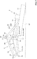
- the top linkage 6 is extended and the detachable frame 30 is tilted backward, as shown in FIG. 6 .
- the detachable frame 30 is held in a posterior tilt by the first portion 38a touching the first regulator portion 41d, as shown in FIG. 4 .
- the working machine 3 is placed on a ground or other ground surface G1 in the working posture, which is a posture for working.
- the tractor 2 is moved backward with the detachable frame 30 tilted backward against the working machine 3 in this working posture, and the second upper coupler portion 33 is positioned below the first upper coupler portion 26, as shown in FIG. 6 .
- the lower linkage 7 is pivoted upward to lift the detachable frame 30, and the second upper coupler portion 33 is engaged with the first upper coupler portion 26.
- the front portion of the working machine 3 is lifted up and the front portion of the working machine 3 moves upward, as shown in FIG. 7 .
- the working machine 3 pivots around the first upper coupling 26 in a direction (forward) approaching close to the detachable frame 30, and the first lower coupling 27 is automatically engaged with the second lower coupler portion 34 in close proximity.
- the PIC shaft 16 is also automatically coupled to the second universal joint 17B. This causes the working machine 3 to be automatically coupled to the tractor 2.
- the locking mechanism provided in the second lower coupler portion 34 is automatically activated, and the locking mechanism regulates the detachment of the first lower coupling 27 from the second lower coupler portion 34.
- the movable member 44 is placed at the third position P3. That is, the movable member 44 is placed at a position where the third portion 38c can be inserted into the engagement groove 41 (lock portion 41c). However, in the state shown in FIG. 7 , the first portion 38a is inserted in the first groove 41a and the upper surface 38e of the second portion 38b is in contact with the lower surface of the plate member 37 (see FIG. 4 ). In other words, the engagement member 38 does not move when the movable member 44 is placed at the third position P3. Thus, when the movable member 44 is positioned at the third position P3, the movable member 44 moves upward relative to the support member 46 and the engagement member 38, and the support member 46 becomes detached from the upper portion 44b of the movable member 44.
- the direct-mounted working machine 3 is coupled to the tractor 2 in the first coupling configuration by the working machine coupler device 1.
- the working machine 3 When turning or moving to a neighboring or remote location, the working machine 3 can be lifted by the hydraulic system 12 and the three-point linkage mechanism 5, and the like, as shown in FIG. 9 .
- the engagement member 38 relatively moves in the engagement groove 41 to allow the top linkage 6 to shorten. That is, the engagement member 38 allows shortening of the top linkage 6 when the engagement member 38 relatively moves in the engagement groove 41 as the working machine 3 lowers to take the working posture from the front lifted position.
- the restriction by the locking mechanism that restricts the first lower coupler portion 27 from being detached from the second lower connecting section 34 is released, and the switching mechanism 39 is placed at the first position P1.
- the release of the locking mechanism can be operated by the operator seat 11 side by, for example, lifting the detachable frame 30.
- the three-point linkage mechanism 5 is moved up and down. That is, when a load is applied to the top linkage 6, the third portion 38c does not come out of the lock portion 41c, so the three-point linkage mechanism 5 is raised and lowered, and when the load on the top linkage 6 becomes zero, the lock on the top linkage 6 is released and the third portion 38c can be removed from the lock portion 41c. When the third portion 38c is removed from the lock portion 41c, the top linkage 6 is free to expand and contract.
- the working machine 3 can be detached from the detachable frame 30 by moving the tractor 2 forward or by moving the tractor 2 forward while gradually lowering after raising the three-point linkage mechanism 5.
- the coupling configuration (second coupling configuration) for coupling the towing working machine 3 (working machine 3 operated in a floating state) to the tractor 2 will be described below.
- the towing working machine 3 includes a grounding wheel (gauge wheel) 48 at the rear portion.
- the grounding wheel 48 is attached to the cover case 21 by a bracket member 49.
- the working machine 3 is also placed on the ground plane G1 in the working posture, which is the working posture.
- the working machine 3 pivots around the first upper coupler portion 26 in a direction approaching close to the detachable frame 30 so that the first lower coupler portion 27 engages with the second lower coupler portion 34 and the PIC shaft 16 is automatically coupled to the second universal coupler portion 17B. This causes the working machine 3 to be automatically coupled to the tractor 2.
- the movable member 44 is placed at the second position P2. That is, the movable member 44 is placed at a position where the second portion 38b can be inserted into the engagement groove 41.
- the first portion 38a is inserted into the first groove 41a and the upper surface 38e of the second portion 38b is in contact with the lower surface of the plate member 37 (see FIG. 4 ).
- the engagement member 38 does not move when the movable member 44 is placed at the third position P3.
- the movable member 44 moves upward relative to the support member 46 and the engagement member 38, and the support member 46 is detached from the upper portion 44b of the movable member 44.
- the towing working machine 3 is connected to the tractor 2 by the working machine coupler device 1.
- the top linkage 6 is not locked to extend and retract, but the top linkage 6 is regulated to extend and retract within a range (a predetermined range) where the second portion 38b moves in the engagement groove 41 relative to the second range E2.
- the working machine 3 is in the floating state that follows the ground plane G1 in the second range E2, where the second portion 38b moves in the engagement groove 41 relative to the ground plane G1.
- the expansion and retraction of the top linkage 6 is regulated within a predetermined range where the second section 38b moves relative to the floating portion 41g (the second groove portion 41b and the lock portion 41c), which allows the working machine 3 to follow the ground plane G1.
- the engagement groove 41 includes the floating portion 41g that regulates the expansion and retraction of the top linkage 6 to a predetermined range (second range E2) when the working machine 3 takes the working posture, allowing the working machine 3 to follow the ground plane G1.
- either the first coupling configuration or the second coupling configuration can be selected by the switching mechanism 39 by selecting the second position P2 or the third position P3.
- the second upper coupler portion 33 when coupling the working machine 3 to the tractor 2, the second upper coupler portion 33 can be positioned below the first upper coupler portion 26 without putting the working machine 3 in a forward inclining posture by tilting the detachable frame 30 backward. This eliminates the need for a stand to hold the working machine 3 in a forward inclining position and allows the working machine 3 to be easily connected.
- a single top linkage controller mechanism 36 can be used to connect both the direct-mounted working machine 3 and the towing working machine 3.
- the working machine coupler device 1 of this embodiment provides the following effects.
- the working machine coupler device includes the top linkage 6 pivotally supported on a traveling vehicle 2 upward and downward, the top linkage 6 being configured to stretch and shorten, the lower linkage 7 pivotally supported on the traveling vehicle 2 upward and downward, the detachable frame 30 connecting the top linkage 6 and the lower linkage 7, the detachable frame 30 including: the second upper coupler 3 to be coupled to a first upper coupler 26 provided to the working machine 3, and the second lower coupler 34 to be coupled to the first lower coupler 27 provided to the working machine 3, and the top linkage controller mechanism 36 to control stretching and shortening of the top linkage 6.
- the second upper coupler 33 of the detachable frame 30 inclining backward is coupled to the first upper coupler 26 when the lower linkage 7 is pivoted upward, and the first lower coupler 27 is configured to move toward and be coupled to the second lower coupler 34 when a front portion of the working machine 3 is moved upward, and the top linkage controller mechanism 36 is configured to regulate the stretching and shortening of the top linkage 6 to hold the detachable frame 30 inclining backward, and allows the top linkage 6 to be shortened until the working machine 3 takes the working posture after the lower linkage 7 is pivoted downward from a state where the front portion of the working machine 3 is lifted.
- the working machine 3 can be connected to the traveling vehicle 2 without having to tilt the working machine 3.
- the top linkage controller mechanism 36 includes the engagement groove 41 and the engagement member 38 that engages with the engagement groove 41, the engagement groove 41 includes the first regulator portion 41d that holds the detachable frame 30 in a backwardly inclining state when the engagement member 38 contacts the engagement groove 41, and the engagement member 38 allows the top linkage 6 to be shortened by moving relative to the engagement groove 41 when the working machine 3 lowers from the front lifting position to the working posture.
- the top linkage controller mechanism 36 can be easily configured.
- the engagement groove 41 includes the lock portion 41c that locks the expansion and retraction of the top linkage 6 by fitting the engagement member 38 when the working machine 3 takes the working posture.
- a direct-mounted work machine 3 can be connected.
- the engagement groove 41 includes the floating portion 41g that regulates the expansion and retraction of the top linkage 6 by fitting the engagement member 38 when the working machine 3 takes the working posture, within a range that allows the working machine 3 to follow the ground plane G1.
- the working machine 3 operated in the floating state can be connected.
- the floating portion 41g includes the second regulator portion 41e that regulates the extension of the top linkage 6 by retracting the engagement member 38 when the lower linkage 7 is pivoted upward to lift the working machine 3 from the working posture.
- the working machine 3 can be lifted when the working machine 3 operated in the floating state is coupled.
- the top linkage controller mechanism 36 includes the switching mechanism 39 that allows selection of one of the first coupling configuration that locks the expansion and retraction of the top linkage 6 when the working machine 3 takes the working posture, and the second coupling configuration that regulates the expansion and retraction of the top linkage 6 to a predetermined range E2 and allows the working machine 3 to follow the ground plane G1 when the working machine 3 takes the working posture.
- the top linkage controller mechanism 36 includes the engagement groove 41 and the engagement member 38 to be engaged with the engagement groove 41
- the engagement groove 41 includes: the first regulator 41d to hold the detachable frame 30 inclining backward with the engagement member 38 contacting to the first regulator 41d, the lock portion to be engaged with the engaged member 38 to lock stretch of the top linkage 6 when the working machine 3 takes the working posture in the first coupling configuration
- the engagement member 38 moves relatively to the engagement groove 41 while the working machine 3 gradually takes the working posture from a posture where the front portion of the working machine 3 is lifted and allows the top linkage 6 to be shortened
- the floating portion 41g includes the second regulator 41e to contact to the engagement member 38 to regulate the stretch of the top linkage 6 when the lower linkage 7 is moved upward to lift the working machine 3 from the working posture.
- the top linkage controller mechanism 36 which can be switched between the first and second coupling configurations, can be easily configured.
- a working machine coupling method which couples the working machine 3 to the traveling vehicle 2 with the working machine coupler device 1 including: the top linkage 6 pivotally supported on the traveling vehicle 2 upward and downward, the top linkage 6 being configured to stretch and shorten; the lower linkage 7 pivotally supported on the traveling vehicle 2 upward and downward; and the detachable frame 30 connecting the top linkage 6 and the lower linkage 7, the detachable frame 30 including: the second upper coupler 33 to be coupled to the first upper coupler 26 provided to the working machine 3; and the second lower coupler 34 to be coupled to the first lower coupler 27 provided to the working machine 3, includes: stretching the top linkage 6 to incline the detachable frame 30 backward; moving the lower linkage 7 upward with respect to the working machine 3 to engage the second upper coupler 33 with the first upper coupler 26 in a state where the detachable frame 30 inclines backward; moving the lower linkage 7 upward to lift a front portion of the working machine 3 after engaging the second upper coupler 33 with the first upper coupler 26, thereby engaging
- the working machine 3 can be connected to the traveling vehicle 2 without having to tilt the working machine 3.
- the direct-mounted working machine 3 can be connected to the traveling vehicle 2.
- the top linkage 6 extends and retracts within a range that allows the working machine 3 to follow the ground plane G1.
Landscapes
- Life Sciences & Earth Sciences (AREA)
- Zoology (AREA)
- Engineering & Computer Science (AREA)
- Mechanical Engineering (AREA)
- Soil Sciences (AREA)
- Environmental Sciences (AREA)
- Agricultural Machines (AREA)
Abstract
Description
- The present invention relates to a working machine coupler device for coupling a working machine to a traveling vehicle and to a working machine coupling method.
- The device disclosed in Patent Document 1 is known as a working machine coupler device for coupling a working machine to a traveling vehicle (tractor).
- The working machine coupler device disclosed in Patent Document 1 includes a three-point linkage mechanism. The three-point linkage mechanism includes a top linkage and a lower linkage pivotally connected to the rear portion of the tractor. The rear portion of the top linkage and the lower linkage are connected by a detachable frame. The working machine includes a first upper coupler portion and a first lower coupler portion. The detachable frame is provided with a second upper coupler portion that engages the first upper coupler portion and a second lower coupler portion that engages the first lower coupler portion.
- To couple the working machine to the tractor, the second upper coupler portion is positioned below the first upper coupler portion, and the second upper coupler portion is engaged with the first upper coupler portion by lifting the lower linkage from this state. Then, when the lower linkage is lifted further, the working machine is lifted up and pivoted forward around the first upper coupler portion. When the working machine pivots forward, the first lower linkage is automatically coupled close to the second lower linkage. In this manner, the working machine is coupled to the tractor.
- [Patent Document 1]
Japanese Unexamined Patent Publication No. H11-243711 - In the working machine coupler device, it is necessary for coupling the working machine to position the second upper coupler portion below the first upper coupler portion. For this reason, the working machine can be tilted forward with respect to a working posture, and thereby the second upper coupler portion can be positioned below the first upper coupler portion. However, depending on a type of the working machine, a stand may be necessary to maintain the forward tilting posture. When a stand is required to maintain the posture during attachment and detachment, the stand requires a large size deteriorating workability, which is impractical, when the working machine is a large implement such as a rear-mounted mower.
- In view of the problems mentioned above, the present invention is intended to provide a working machine coupler device and a working machine coupling method that enables a working machine to be coupled to a traveling vehicle without having to tilt the working machine.
- A working machine coupler device according to one aspect of the present invention, includes: a top linkage pivotally supported on a traveling vehicle upward and downward, the top linkage being configured to stretch and shorten; a lower linkage pivotally supported on the traveling vehicle upward and downward; a detachable frame connecting the top linkage and the lower linkage, the detachable frame including: a second upper coupler to be coupled to a first upper coupler provided to a working machine; and a second lower coupler to be coupled to a first lower coupler provided to the working machine; and a top linkage controller mechanism to control stretching and shortening of the top linkage. The second upper coupler of the detachable frame inclining backward is coupled to the first upper coupler when the lower linkage is pivoted upward, and the first lower coupler is configured to move toward and be coupled to the second lower coupler when a front portion of the working machine is moved upward, and the top linkage controller mechanism is configured to regulate the stretching and shortening of the top linkage to hold the detachable frame inclining backward, and allows the top linkage to be shortened until the working machine takes a working posture after the lower linkage is pivoted downward from a state where the front portion of the working machine is lifted.
- In addition, the top linkage control mechanism includes: an engagement groove; and an engagement member to be engaged with the engagement groove, the engagement groove includes a first regulator to hold the detachable frame inclining backward with the engagement member contacting to the first regulator, and the engagement member moves relatively to the engagement groove while the working machine gradually takes a working posture from a posture where a front portion of the working machine is lifted and allows the top linkage to be shortened.
- In addition, the engagement groove includes a lock portion to be engaged with the engaged member to lock stretch of the top linkage when the working machine takes the working posture.
- In addition, the engagement groove includes a floating portion to be engaged with the engagement member to regulate stretch of the top linkage within a range allowing the working machine to follow a ground surface when the working machine takes the working posture.
- In addition, the floating portion includes a second regulator to contact to the engagement member to regulate the stretch of the top linkage when the lower linkage is moved upward to lift the working machine from the working posture.
- In addition, the top linkage controller mechanism includes a switching mechanism to selectively take either a first coupling configuration to lock the stretch of the top linkage when the working machine takes the working posture or a second coupling configuration to regulate the stretch of the top linkage within the range allowing the working machine to follow a ground surface when the working machine takes the working posture.
- In addition, the top linkage controller mechanism includes an engagement groove and an engagement member to be engaged with the engagement groove, the engagement groove includes: a first regulator to hold the detachable frame inclining backward with the engagement member contacting to the first regulator, a lock portion to be engaged with the engaged member to lock stretch of the top linkage when the working machine takes the working posture in the first coupling configuration, a floating portion to be engaged with the engagement member to regulate stretch of the top linkage within a range allowing the working machine to follow a ground surface when the working machine takes the working posture in the second coupling configuration, the engagement member moves relatively to the engagement groove while the working machine gradually takes a working posture from a posture where a front portion of the working machine is lifted and allows the top linkage to be shortened, and the floating portion includes a second regulator to contact to the engagement member to regulate the stretch of the top linkage when the lower linkage is moved upward to lift the working machine from the working posture.
- In addition, a working machine coupling method according to one aspect of the present invention, which couples a working machine to a traveling vehicle with a working machine coupler device including: a top linkage pivotally supported on a traveling vehicle upward and downward, the top linkage being configured to stretch and shorten; a lower linkage pivotally supported on the traveling vehicle upward and downward; and a detachable frame connecting the top linkage and the lower linkage, the detachable frame including: a second upper coupler to be coupled to a first upper coupler provided to a working machine; and a second lower coupler to be coupled to a first lower coupler provided to the working machine, includes: stretching the top linkage to incline the detachable frame backward; moving the lower linkage upward with respect to the working machine to engage the second upper coupler with the first upper coupler in a state where the detachable frame inclines backward; moving the lower linkage upward to lift a front portion of the working machine after engaging the second upper coupler with the first upper coupler, thereby engaging the second lower coupler with the first lower coupler; and moving the lower linkage downward until the working machine takes a working posture from a state where the front portion of the working machine is lifted.
- In addition, the working machine coupling method mentioned above, includes locking stretch of the top linkage when the working machine takes the working posture.
- In addition, the working machine coupling method mentioned above, includes regulating stretch of the top linkage within a range allowing the working machine to follow a ground surface when the working machine takes the working posture.
- According to the present invention, it is possible to couple a working machine to a raveling device without inclining the working machine.
-
-
FIG. 1 is a schematic side view illustrating a state where a working machine is coupled to a traveling vehicle with a working machine coupler device. -
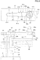
FIG. 2 is a view illustrating a top linkage controller mechanism that locks stretch of a top linkage, including a plan view on the upper side and a side view on the lower side. -
FIG. 3 is an enlarged view of a main portion of a top linkage mechanism, including a plan view on the upper side and a side view on the lower side. -
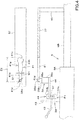
FIG. 4 is a view of a top linkage mechanism, including a plan view on the upper side and a side view on the lower side. -
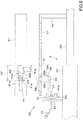
FIG. 5 is a view of a top linkage mechanism, including a plan view on the upper side and a side view on the lower side. -
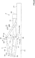
FIG. 6 is a side view illustrating a state before coupling of a direct-mounting working machine. -
FIG. 7 is a side view illustrating a state where a direct-mounting working machine is coupled to a detachable frame. -
FIG. 8 is a side view illustrating a state where a direct-mounting working machine takes a working machine. -
FIG. 9 is a side view illustrating a state where a direct-mounting working machine is lifted. -
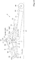
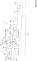
FIG. 10 is a side view illustrating a state before coupling of a towing working machine. -
FIG. 11 is a side view illustrating a state where a towing working machine is coupled to a detachable frame. -
FIG. 12 is a side view illustrating a state where a towing working machine takes a working posture. -
FIG. 13 is a side view illustrating a state where a towing working machine is lifted. - Hereinafter, an embodiment of the present invention will be described with appropriate reference to the drawings.
-
FIG. 1 is a schematic side view of a working machine coupler device 1 according to this embodiment. The working machine coupler device 1 is a device for connecting a workingmachine 3 to a travelingvehicle 2. In this embodiment, a tractor is illustrated as thetraveling vehicle 2. The traveling vehicle is hereafter referred to as thetractor 2. A rear-mounted mower (rear cutter) or other ground working machine is exemplified as theworking machine 3. - In this embodiment, a direction of an arrowed line A1 direction in
FIG. 1 (a forward direction of the tractor 2) is referred to as the front, and a direction of an arrowed line A2 inFIG. 1 (a backward direction of the tractor 1) is referred to as the rear. Thus, the front surface side ofFIG. 1 is referred to the left, and the back surface side ofFIG. 1 is referred to the right. The horizontal direction orthogonal to the front-to-rear direction A3 is explained as a vehicle width direction. The direction from the center to the right or left portion of the vehicle width direction intractor 2 is explained as the outside of the vehicle (also referred to as a vehicle outward direction). In other words, the vehicle outward direction is the direction in the vehicle width direction separating away from the center of thetractor 2. A direction opposite to the vehicle outward direction is explained as a vehicle inward direction (also referred to as a vehicle inward direction). In other words, the vehicle inward direction is the direction in the vehicle width direction approaching closer to the center of thetractor 2. - As shown in
FIG. 1 , thetractor 2 includes avehicle body 4. Thevehicle body 4 includes, for example, a prime mover as a power source, a flywheel housing that houses a flywheel, a clutch housing that houses a clutch for intermittently transmitting the power of the prime mover transmitted through the flywheel, and a transmission case that houses a transmission for shifting the power transmitted through the clutch, which are arranged and directly connected in a front-to-rear direction of the vehicle body. The prime mover is, for example, a diesel engine. - The
tractor 2 includes anoperator seat 11 and ahydraulic system 12 mounted on the rear portion of thevehicle body 4. Thehydraulic system 12 includes aleft lift arm 13L arranged on the left side of thebody 12A and aright lift arm 13R arranged on the right side of thebody 12A. Thelift arms rotation shaft 14 whose front portion includes a horizontal axial center (axial center extending in the vehicle width direction) and can be pivoted up and down by rotating therotation shaft 14 around the axial center in the hydraulic driving. The upper portion of theleft lift rod 22L is rotatably connected to the rear portion of thelift arm 13L, and the upper portion of theright lift rod 22R is rotatably connected to the rear portion of thelift arm 13R, which is rotatably connected to the rear portion of thelift arm 13R. - On the back of the
vehicle body 4, aPTO shaft 15 is provided; thePTO shaft 15 is a power take-out shaft that takes power from the prime mover externally; thePTO shaft 15 is interlocked with thePIC shaft 18 of the workingmachine 3 via adrive shaft 17. Thedrive shaft 17, for example, consists of a universal joint and includes a firstuniversal joint 17A, a second universal joint 17B, and ajoint shaft 17C. The first universaljoint portion 17A is connected to thePTO shaft 15. The second universal joint 17B is connected to thePIC axis 18. Thejoint shaft 17C connects and interlock the first universaljoint portion 17A and the second universaljoint portion 17B. Thejoint shaft 17C is freely telescopic in length. The term "telescoping" means that it is free to stretch and shorten in length. The term "stretching" means that the length is increased, and the term "shortening" means that the length is reduced. - The rear portion of
tractor 2 is provided with atop linkage bracket 23, a leftlower linkage bracket 24L and a rightlower linkage bracket 24R. Thetop linkage bracket 23 is fixed to the upper rear portion of thevehicle body 4. Thelower linkage bracket 24L is fixed to the left rear bottom of thevehicle body 4. The lower linkage bracket R is fixed to the right rear bottom of thevehicle body 4. - The
PIC shaft 18 is an input shaft for inputting power transmitted from thetractor 2 through thedrive shaft 17 to the workingmachine 3. The power transmitted to thePIC shaft 18 is input to the transmission mechanism in thetransmission case 20 through thetransmission shaft 19. The power transmitted to the transmission mechanism in thetransmission case 20 is transmitted to a ground working device provided in thecover case 21. The ground working device is, for example, a mower device including a mower blade (mowing blade) that mows the grass, a drive mechanism to drive the mower blade, and the like, as a rear-mounted mower. - As shown in
FIG. 1 , the workingmachine 3 includes anattachment frame 25. Theattachment frame 25 includes afirst frame member 25A and asecond frame member 25B. Thefirst frame member 25A is provided in an inclined manner that transitions upward from thecover case 21 toward the front. A firstupper coupler portion 26 is provided in the front upper portion of thefirst frame member 25A. The firstupper coupler portion 26 consists, for example, of a pin having a transverse axis center. Asecond frame member 25B is provided extending forward on thecover case 21. A firstlower coupler portion 27L and a firstlower coupler portion 27R are provided at the front portion of thesecond frame member 25B. The firstlower coupler portion 27L is located on the left side of the workingmachine 3, and the firstlower coupler portion 27R is located on the right side of the workingmachine 3. The firstlower coupler portion 27L and the firstlower coupler portion 27R are formed of a pin with a transverse axis center, for example. - As shown in
FIG. 1 , the working machine coupler device 1 includes a three-point linkage mechanism 5 attached to the rear portion of thetractor 2. The three-point linkage mechanism 5 includes onetop linkage 6 and two lower linkages 7 (lower linkage 7L andlower linkage 7R). Thetop linkage 6 is located in the center of the vehicle width direction of thevehicle body 4 and above thelower linkage 7L and thelower linkage 7R. Thetop linkage 6 includes a cylinder (first member) 6A and a rod member (second member) 6B. The front portion of the top linkage 6 (cylinder 6A) is rotatably connected to thetop linkage bracket 23 via apivot axis 28 to rotate freely around the horizontal axis center. Therod member 6B is inserted into thecylinder 6A freely in and out of the rear portion. Therod member 6B is movable in the longitudinal direction of thetop linkage 6. That is, thetop linkage 6 is stretchable in length. - The
top linkage 6 may be configured such that therod member 6B is located to the front and thecylinder 6A is located to the rear. In this case, therod member 6B is pivoted to thetop linkage bracket 23 and thecylinder 6A is pivoted to thedetachable frame 30 described below. - The
lower linkage 7L is rotatably connected at the front to the leftlower linkage bracket 24L via apivot axis 29 around the transverse axis center. The lower portion of theleft lift arm 13L is pivotally connected to the middle portion of thelower linkage 7L in the longitudinal direction. The front portion of thelower linkage 7R is rotatably connected to the rightlower linkage bracket 24R via apivot axis 29 to the rightlower linkage bracket 24R, which is rotatably connected around the horizontal axis center. The lower portion of theright lift arm 13R is pivotally connected to the middle of thelower linkage 7R in the longitudinal direction. Thus, thelower linkage 7L and thelower linkage 7R can be raised and lowered (pivoted up and down) by pivoting thelift arm 13L and thelift arm 13R up and down by the pivotingaxis 14. - The rear portion of the
top linkage 6 and the rear portion of thelower linkages detachable frame 30. The rear portion of the top linkage 6 (rod member 6B) is rotatably connected to the upper portion of thedetachable frame 30 via apivot axis 31, which is rotatable around the horizontal axis center. The rear portion of thelower linkage 7L is rotatably connected to the lower and left side of thedetachable frame 30 via thepivot axis 32 in the transverse axis. The rear portion of thelower linkage 7R is rotatably coupled at the bottom and on the right side of thedetachable frame 30 via thepivot axis 32 in the lower portion of thedetachable frame 30 and rotatably around the transverse axis. - In the following description, the
lower linkage 7L and thelower linkage 7R may be collectively referred to as thelower linkage 7. - On the upper portion of the
detachable frame 30, a secondupper coupler portion 33 is provided which engages the firstupper coupler portion 26. The secondupper coupler portion 33 includes a groove which opens upwardly and allows the firstupper coupler portion 26 to be inserted, and is formed in the form of a hook. Thus, the secondupper coupler portion 33 can be engaged with the firstupper coupler portion 26 from below. The workingmachine 3 can be rotated around the firstupper coupler portion 26 with the secondupper coupler portion 33 engaged with the firstupper coupler portion 26. In other words, the workingmachine 3 is pivotable in the direction of proximity and detachment with respect to thedetachable frame 30 with the secondupper coupler portion 33 engaged with the firstupper coupler portion 26. - The lower portion of the
detachable frame 30 is provided with a secondlower coupler portion 34L that engages the firstlower coupler portion 27L and the secondlower coupler portion 34R that engages the firstlower coupler portion 27R. The secondlower coupler portion 34L includes a groove that is open toward the rear and into which the firstlower coupler portion 27L can be inserted. The firstlower coupler portion 27L can engage with the secondlower coupler portion 34L when the workingmachine 3 is pivoted around the firstupper coupler portion 26 in a direction approaching close to thedetachable frame 30. The secondlower coupler portion 34R includes a groove that opens backward and allows the firstlower coupler portion 27R to be inserted thereto. The firstlower coupler portion 27R can engage with the secondlower coupler portion 34R when the workingmachine 3 pivots around the firstupper coupler portion 26 in a direction approaching close to thedetachable frame 30. The secondlower coupler portion 34L is provided with a locking mechanism (not shown in the drawings) that regulates the firstlower coupler portion 27L to be detached from the secondlower coupler portion 34L. The secondlower coupler portion 34R is also provided with a locking mechanism (figure omitted) that regulates detachment of the firstlower coupler portion 27R from the secondlower coupler portion 34R. - In the following description, the first
lower coupler portion 27L and the firstlower coupler portion 27R are collectively referred to as the firstlower coupler portion 27, and the secondlower coupler portion 34L and the secondlower coupler portion 34R may be collectively referred to as the secondlower coupler portion 34. - At the middle portion of the
detachable frame 30 in the vertical direction, the second universaljoint portion 17B of thedrive shaft 17 is pivotally supported up and down (pivotable). This allows the PIC shaft 16 to automatically couple to the second universal joint 17B when the workingmachine 3 is pivoted in a direction proximate to thedetachable frame 30 around the firstupper coupler portion 26. - As shown in
FIG. 1 , the workingmachine 3 includes a toplinkage controller mechanism 36 that controls the stretching and shortening of thetop linkage 6. - As shown in
FIG. 2 , the toplinkage controller mechanism 36 includes aplate member 37, an engagement member (engagement pin) 38, and aswitching mechanism 39. - As shown in
FIG. 2 , theplate member 37 is formed of a plate material long in the length direction of thetop linkage 6 and is arranged above thetop linkage 6. Theplate member 37 is arranged over thecylinder 6A from therod member 6B, and one end side (rear) is attached to therod member 6B by thesupport member 40. Thus, theplate member 37 moves in synchronization with therod member 6B. Theplate member 37 includes anengagement groove 41 with which theengagement member 38 engages. Theengagement groove 41 is formed in the front portion of theplate member 37. Theengagement groove 41 is a groove formed through theplate member 37 and is formed in a long groove elongated in the length direction of thetop linkage 6. - As shown in
FIG. 3 , theengagement groove 41 includes afirst groove portion 41a, asecond groove portion 41b, and a lock portion (locking hole) 41c. Thefirst groove portion 41a includes the front portion of theengagement groove 41 and is formed into a long groove in the longitudinal direction of theplate member 37. Thesecond groove 41b includes the middle portion of theengagement groove 41 and is formed in a long groove in the longitudinal direction of theplate member 37. Thesecond groove portion 41b is formed continuously with thefirst groove portion 41a. Thelock portion 41c includes a rear portion of theengagement groove 41 and is formed to be a circular hole. Thelock portion 41c is formed in continuity with thesecond groove portion 41b. Thesecond groove portion 41b and thelock portion 41c include a floatingportion 41g. - As shown in
FIG. 3 , thesecond groove portion 41b has a wider groove width than thefirst groove portion 41a. In other words, the groove width W1 of thefirst groove portion 41a is narrower than the groove width W2 of thesecond groove portion 41b. Thelock portion 41c is formed to be a hole of diameter W3, which is larger than the groove width W2 of thesecond groove portion 41b. - As shown in
FIG. 3 , theengagement member 38 is formed of a stepped pin having a plurality of sites of different diameters. In detail, theengagement member 38 includes afirst portion 38a in the upper portion, a second portion (semi-locking engagement portion) 38b in the middle of the vertical direction, and a third portion (locking engagement portion) 38c in the lower portion. Thefirst portions 38a,second portions 38b andthird portions 38c are formed in a cylindrical and concentric shape. Thesecond portion 38b is formed to have a larger diameter than thefirst portion 38a, and thethird portion 38c is formed to have a larger diameter than thesecond portion 38b. - As shown in
FIG. 3 , theengagement member 38 is located on the lower side of theengagement groove 41 and is supported by theswitching mechanism 39 such that a vertical position is changeable (changeable in the direction of proximity and separation from the engagement groove 41). In detail, theswitching mechanism 39 supports theengagement member 38 to be movable between a position where thefirst portion 38a can be inserted into the engagement groove 41 (first groove 41a) (seeFIG. 4 ), a position where thesecond portion 38b can be inserted into the engagement groove 41 (second groove 41b) (seeFIG. 5 ), and a position where thefirst portion 38c can be inserted into the engagement groove 41 (lockportion 41c) (seeFIG. 2 ). - As shown in
FIG. 4 , the diameter D1 of thefirst portion 38a is formed in a dimension roughly equal to the groove width W1 of thefirst groove 41a. Thefirst portion 38a is insertable into thefirst groove 41a and can move along the longitudinal direction in thefirst groove 41a, relative to thefirst groove 41a. Thus, thefirst portion 38a is able to move between the front end and the rear end of theengagement groove 41 relative to theengagement groove 41. In detail, thefirst portion 38a is movable relative to theengagement groove 41 in an area (first range) E1 between thefirst regulator portion 41d that is the end (front end) of thefirst groove 41a and the rear end of thelock portion 41c. In other words, thetop linkage 6 is extendable and retractable to the extent that thefirst region 38a moves relative to the first range E1 in a state where thefirst region 38a is located in theengagement groove 41. - As shown in
FIG. 5 , the diameter D2 of thesecond portion 38b is formed to have a dimension roughly equal to the groove width W2 of thesecond groove 41b. Thesecond portion 38b can be inserted into thesecond groove 41b and can move along the longitudinal direction in thesecond groove 41b relative to thesecond groove 41b. Thus, thesecond portion 38b is able to move relative to theengagement groove 41 in the rang e(second range) E2 between thesecond regulator portion 41e that is the end (front end) of thesecond groove 41b and the rear end of thelock portion 41c. In other words, thetop linkage 6 is extendable and retractable to the extent that thesecond portion 38b moves relative to the second range E2 in the state where thesecond portion 38b is located in theengagement groove 41. The second range E2 in which thesecond site 38b moves relative to theengagement groove 41 is narrower than the first range E1 in which thefirst portion 38a moves relative to theengagement groove 41. - As shown in
FIG. 2 andFIG. 3 , the diameter D3 of thethird portion 38c is formed to have the same diameter as the diameter W3 of thelock portion 41c. Thethird portion 38c can be inserted into thelock portion 41c. Thus, when thethird portion 38c is fitted into thelock portion 41c, thetop linkage 6 is unable to extend and retract. That is, the extension and retraction of thetop linkage 6 is locked. - As shown in
FIG. 3 , theswitching mechanism 39 includes an operation lever (operating member) 42, a fixedmember 43, amovable member 44, asupport member 46, and a biasingspring 47. - The
operation lever 42 is a member that operates the switching mechanism 39 (movable member 44) and extends to the vicinity of theoperator seat 11, as shown inFIG. 1 , and can be operated by an operator seated on theoperator seat 11. - As shown in
FIG. 3 , the fixedmember 43 is fixed to thecylinder 6A, and the base of theoperation lever 42 is engaged so as to be adjustable in the vertical position. Themovable member 44 is fixed to the base of theoperation lever 42. Thesupport member 46 is supported by themovable member 44 at one end (front portion) 46a, which can be moved up and down. Thesupport member 46 protrudes rearwardly from themovable member 44, and theengagement member 38 is fixed to the other end (rear portion) 46b of thesupport member 46. The biasingspring 47 includes a compression spring and is interposed in a compressed manner between oneend side 46a of thesupport member 46 and thelower portion 44a of themovable member 44. Thus, the biasingspring 47 displaces thesupport member 46 upwardly. Thesupport member 46 includes oneend side 46a in contact with theupper portion 44b of themovable member 44, thereby regulating its upward movement. Thesupport member 46 is capable of moving downward against the force of the biasing spring 47 (spring force). - As shown in
FIG. 3 , themovable member 44 can be repositioned to a first position PI, a second position P2, and a third position P3. The first position P1 is a position where thefirst portion 38a can be inserted into theengagement groove 41, as shown inFIG. 4 . The second position P2 is a position where thesecond portion 38b can be inserted into theengagement groove 41, as shown inFIG. 5 . The third position P3 is a position where thethird portion 38c can be inserted into theengagement groove 41, as shown inFIG. 2 andFIG. 3 . - The
movable member 44 is operable by an operator seated on theoperator seat 11 by means of theoperation lever 42 to change the position between the first position PI, the second position P2 and the third position P3. In detail, theoperation lever 42 is detachably engaged and disengaged to the fixedmember 43 with themovable member 44 in the first position PI, the second position P2 and the third position P3. In other words, theoperation lever 42 is engaged with the fixedmember 43 to hold themovable member 44 at the first position PI, the second position P2 or the third position P3. By releasing the engagement of theoperation lever 42 to the fixedmember 43, themovable member 44 can be repositioned. - The top
linkage controller mechanism 36 described in this embodiment is an example and is not limited to the aforementioned configuration. For example, theengagement member 38 and theswitching mechanism 39 may be provided on therod member 6B and theplate member 37 may be provided on thecylinder 6A. Therod member 6B may be pivoted to thetop linkage bracket 23 and thecylinder 6A may be pivoted to thedetachable frame 30. - Next, referring to
FIG. 6 to FIG. 9 , the coupling configuration (first coupling configuration) of coupling the direct-mountedworking machine 3 to thetractor 2 will be described. - In the first coupling configuration, the
movable member 44 is first placed at the first position P1, as shown inFIG. 4 . That is, thefirst portion 38a is positioned in theengagement groove 41 and is capable of relatively moving relative in the first range E1. Before coupling the workingmachine 3, thetop linkage 6 is extended and thedetachable frame 30 is tilted backward, as shown inFIG. 6 . At this time, as shown inFIG. 4 , thedetachable frame 30 is held in a posterior tilt by thefirst portion 38a touching thefirst regulator portion 41d, as shown inFIG. 4 . Meanwhile, the workingmachine 3 is placed on a ground or other ground surface G1 in the working posture, which is a posture for working. Thetractor 2 is moved backward with thedetachable frame 30 tilted backward against the workingmachine 3 in this working posture, and the secondupper coupler portion 33 is positioned below the firstupper coupler portion 26, as shown inFIG. 6 . - Next, the
lower linkage 7 is pivoted upward to lift thedetachable frame 30, and the secondupper coupler portion 33 is engaged with the firstupper coupler portion 26. Then, when thedetachable frame 30 is lifted further, the front portion of the workingmachine 3 is lifted up and the front portion of the workingmachine 3 moves upward, as shown inFIG. 7 . As the front portion of the workingmachine 3 moves upward, the workingmachine 3 pivots around the firstupper coupling 26 in a direction (forward) approaching close to thedetachable frame 30, and the firstlower coupling 27 is automatically engaged with the secondlower coupler portion 34 in close proximity. At this time, the PIC shaft 16 is also automatically coupled to the seconduniversal joint 17B. This causes the workingmachine 3 to be automatically coupled to thetractor 2. When the firstlower coupling 27 is engaged with the secondlower coupler portion 34, the locking mechanism provided in the secondlower coupler portion 34 is automatically activated, and the locking mechanism regulates the detachment of the firstlower coupling 27 from the secondlower coupler portion 34. - Next, the
movable member 44 is placed at the third position P3. That is, themovable member 44 is placed at a position where thethird portion 38c can be inserted into the engagement groove 41 (lockportion 41c). However, in the state shown inFIG. 7 , thefirst portion 38a is inserted in thefirst groove 41a and theupper surface 38e of thesecond portion 38b is in contact with the lower surface of the plate member 37 (seeFIG. 4 ). In other words, theengagement member 38 does not move when themovable member 44 is placed at the third position P3. Thus, when themovable member 44 is positioned at the third position P3, themovable member 44 moves upward relative to thesupport member 46 and theengagement member 38, and thesupport member 46 becomes detached from theupper portion 44b of themovable member 44. - Next, from the state in which the front portion of the working
machine 3 is moved upward (forward inclining state), as shown inFIG. 7 , thelower linkage 7 is pivoted downward to lower thedetachable frame 30. Then, the front portion of the workingmachine 3 is lowered and the front portion of the workingmachine 3 is lowered to take the working posture shown inFIG. 8 . As the front portion of the workingmachine 3 lowers, thetop linkage 6 shortens and theplate member 37 moves forward with respect to theengagement member 38. In other words, theengagement member 38 moves backward relative to theengagement groove 41. When theengagement member 38 moves to a position corresponding to thesecond groove 41b as thetop linkage 6 shortens, thesupport member 40 and theengagement member 38 are lifted by the force the biasingspring 47, so that thesecond portion 38b fits into thesecond groove 41b and theupper surface 38d of thethird portion 38c touches the lower surface of the plate member 37 (seeFIG. 5 ). - Then, as shown in
FIG. 8 , when the workingmachine 3 touches the ground plane G1 and takes the working posture, the position of theengagement member 38 coincides with thelock portion 41c, and thesupport member 46 moves upward by the force of the biasingspring 47, causing thethird portion 38c to insert into thelock portion 41c (seeFIG. 2 andFIG.3 ). The expansion and retraction of thetop linkage 6 is locked when thethird portion 38c fits into thelock portion 41c. - In this manner, the direct-mounted
working machine 3 is coupled to thetractor 2 in the first coupling configuration by the working machine coupler device 1. - When turning or moving to a neighboring or remote location, the working
machine 3 can be lifted by thehydraulic system 12 and the three-point linkage mechanism 5, and the like, as shown inFIG. 9 . - As mentioned above, when the working
machine 3 takes the working posture from the front lifted state, theengagement member 38 relatively moves in theengagement groove 41 to allow thetop linkage 6 to shorten. That is, theengagement member 38 allows shortening of thetop linkage 6 when theengagement member 38 relatively moves in theengagement groove 41 as the workingmachine 3 lowers to take the working posture from the front lifted position. - In detaching the working
machine 3, the restriction by the locking mechanism that restricts the firstlower coupler portion 27 from being detached from the second lower connectingsection 34 is released, and theswitching mechanism 39 is placed at the first position P1. The release of the locking mechanism can be operated by theoperator seat 11 side by, for example, lifting thedetachable frame 30. - To bring the
switching mechanism 39 to the first position P1, the three-point linkage mechanism 5 is moved up and down. That is, when a load is applied to thetop linkage 6, thethird portion 38c does not come out of thelock portion 41c, so the three-point linkage mechanism 5 is raised and lowered, and when the load on thetop linkage 6 becomes zero, the lock on thetop linkage 6 is released and thethird portion 38c can be removed from thelock portion 41c. When thethird portion 38c is removed from thelock portion 41c, thetop linkage 6 is free to expand and contract. - In this state, the working
machine 3 can be detached from thedetachable frame 30 by moving thetractor 2 forward or by moving thetractor 2 forward while gradually lowering after raising the three-point linkage mechanism 5. - Next, referring to
FIG. 10 to FIG. 13 , the coupling configuration (second coupling configuration) for coupling the towing working machine 3 (workingmachine 3 operated in a floating state) to thetractor 2 will be described below. - As shown in
FIG. 10 , thetowing working machine 3 includes a grounding wheel (gauge wheel) 48 at the rear portion. Thegrounding wheel 48 is attached to thecover case 21 by abracket member 49. When thistowing working machine 3 is connected, the workingmachine 3 is also placed on the ground plane G1 in the working posture, which is the working posture. - In the case of coupling the towing
type working machine 3, the workingmachine 3 is lifted up and the PIC shaft 16 is automatically connected to the seconduniversal coupler portion 17B as well as the firstlower coupler portion 27 to the secondlower coupler portion 34 until the PIC shaft 16 is automatically connected to the seconduniversal coupler portion 17B, in the same manner as in the case of coupling the direct-mountedworking machine 3 described above. - That is, with the
movable member 44 at the first position PI, and with thetop linkage 6 extended and thedetachable frame 30 tilted backward, as shown inFIG. 10 , thetractor 2 is moved backward to position the secondupper coupler portion 33 below the firstupper coupler portion 26. Then, from this state, thelower linkage 7 is pivoted upward to raise thedetachable frame 30, and the secondupper coupler portion 33 is engaged with the firstupper coupler portion 26. Then, when thedetachable frame 30 is raised further, the workingmachine 3 is lifted and the front portion of the workingmachine 3 moves upward, as shown inFIG. 11 . As the front portion of the workingmachine 3 moves upward, the workingmachine 3 pivots around the firstupper coupler portion 26 in a direction approaching close to thedetachable frame 30 so that the firstlower coupler portion 27 engages with the secondlower coupler portion 34 and the PIC shaft 16 is automatically coupled to the seconduniversal coupler portion 17B. This causes the workingmachine 3 to be automatically coupled to thetractor 2. - Next, in this second coupling configuration, the
movable member 44 is placed at the second position P2. That is, themovable member 44 is placed at a position where thesecond portion 38b can be inserted into theengagement groove 41. However, in the state shown inFIG. 11 , thefirst portion 38a is inserted into thefirst groove 41a and theupper surface 38e of thesecond portion 38b is in contact with the lower surface of the plate member 37 (seeFIG. 4 ). In other words, theengagement member 38 does not move when themovable member 44 is placed at the third position P3. Thus, when themovable member 44 is positioned at the second position P2, themovable member 44 moves upward relative to thesupport member 46 and theengagement member 38, and thesupport member 46 is detached from theupper portion 44b of themovable member 44. - Next, from the forward inclining state in which the front portion of the working
machine 3 is moved upward, as shown inFIG. 11 , thelower linkage 7 is pivoted downward to lower thedetachable frame 30. Then the front portion of the workingmachine 3 is lowered and the working posture of the workingmachine 3 is shown inFIG. 12 . As the front portion of the workingmachine 3 lowers, thetop linkage 6 shortens and theplate member 37 moves forward with respect to theengagement member 38. In other words, theengagement member 38 moves backward relative to theengagement groove 41. When theengagement member 38 moves to a position corresponding to thesecond groove 41b as thetop linkage 6 shortens, thesupport member 40 and theengagement member 38 are raised by the force of the biasingspring 47, so that thesecond portion 38b fits into thesecond groove 41b and theupper surface 38d of thethird portion 38c touches the lower surface of the plate member 37 (seeFIG. 5 ). - In this manner, the
towing working machine 3 is connected to thetractor 2 by the working machine coupler device 1. - In the coupling configuration of the
towing working machine 3, when the workingmachine 3 takes the working posture shown inFIG. 12 , thetop linkage 6 is not locked to extend and retract, but thetop linkage 6 is regulated to extend and retract within a range (a predetermined range) where thesecond portion 38b moves in theengagement groove 41 relative to the second range E2. In other words, the workingmachine 3 is in the floating state that follows the ground plane G1 in the second range E2, where thesecond portion 38b moves in theengagement groove 41 relative to the ground plane G1. In other words, the expansion and retraction of thetop linkage 6 is regulated within a predetermined range where thesecond section 38b moves relative to the floatingportion 41g (thesecond groove portion 41b and thelock portion 41c), which allows the workingmachine 3 to follow the ground plane G1. Thus, theengagement groove 41 includes the floatingportion 41g that regulates the expansion and retraction of thetop linkage 6 to a predetermined range (second range E2) when the workingmachine 3 takes the working posture, allowing the workingmachine 3 to follow the ground plane G1. - In this second coupling configuration of coupling the
towing working machine 3, when the workingmachine 3 is turned or moved to a neighboring or remote location, thesecond portion 38b moves forward relative to the floatingportion 41g when the workingmachine 3 is lifted by thehydraulic system 12, the three-point linkage mechanism 5, and the like. When thesecond portion 38b moves to the front end of the floatingportion 41g and touches thesecond regulation portion 41e, the extension of thetop linkage 6 is regulated. This allows the workingmachine 3 to be regulated to lower and lift the workingmachine 3, as shown inFIG. 13 . - As described above, when the front portion of the working
machine 3 is moved downward from the upwardly lifted position to the working posture, either the first coupling configuration or the second coupling configuration can be selected by theswitching mechanism 39 by selecting the second position P2 or the third position P3. - In the second coupling configuration, in which the
towing working machine 3 is connected to the travelingvehicle 2, the detachment of the workingmachine 3 is performed in much the same way as the direct-mountedworking machine 3 described above. - As described in detail above, in the working machine coupler device 1 of the present embodiment, when coupling the working
machine 3 to thetractor 2, the secondupper coupler portion 33 can be positioned below the firstupper coupler portion 26 without putting the workingmachine 3 in a forward inclining posture by tilting thedetachable frame 30 backward. This eliminates the need for a stand to hold the workingmachine 3 in a forward inclining position and allows the workingmachine 3 to be easily connected. - A single top
linkage controller mechanism 36 can be used to connect both the direct-mountedworking machine 3 and thetowing working machine 3. - In addition, the working machine coupler device 1 of this embodiment provides the following effects.
- The working machine coupler device includes the
top linkage 6 pivotally supported on a travelingvehicle 2 upward and downward, thetop linkage 6 being configured to stretch and shorten, thelower linkage 7 pivotally supported on the travelingvehicle 2 upward and downward, thedetachable frame 30 connecting thetop linkage 6 and thelower linkage 7, thedetachable frame 30 including: the secondupper coupler 3 to be coupled to a firstupper coupler 26 provided to the workingmachine 3, and the secondlower coupler 34 to be coupled to the firstlower coupler 27 provided to the workingmachine 3, and the toplinkage controller mechanism 36 to control stretching and shortening of thetop linkage 6. The secondupper coupler 33 of thedetachable frame 30 inclining backward is coupled to the firstupper coupler 26 when thelower linkage 7 is pivoted upward, and the firstlower coupler 27 is configured to move toward and be coupled to the secondlower coupler 34 when a front portion of the workingmachine 3 is moved upward, and the toplinkage controller mechanism 36 is configured to regulate the stretching and shortening of thetop linkage 6 to hold thedetachable frame 30 inclining backward, and allows thetop linkage 6 to be shortened until the workingmachine 3 takes the working posture after thelower linkage 7 is pivoted downward from a state where the front portion of the workingmachine 3 is lifted. - According to this configuration, the working
machine 3 can be connected to the travelingvehicle 2 without having to tilt the workingmachine 3. - The top
linkage controller mechanism 36 includes theengagement groove 41 and theengagement member 38 that engages with theengagement groove 41, theengagement groove 41 includes thefirst regulator portion 41d that holds thedetachable frame 30 in a backwardly inclining state when theengagement member 38 contacts theengagement groove 41, and theengagement member 38 allows thetop linkage 6 to be shortened by moving relative to theengagement groove 41 when the workingmachine 3 lowers from the front lifting position to the working posture. - According to this configuration, the top
linkage controller mechanism 36 can be easily configured. - The
engagement groove 41 includes thelock portion 41c that locks the expansion and retraction of thetop linkage 6 by fitting theengagement member 38 when the workingmachine 3 takes the working posture. - According to this configuration, for example, a direct-mounted
work machine 3 can be connected. - The
engagement groove 41 includes the floatingportion 41g that regulates the expansion and retraction of thetop linkage 6 by fitting theengagement member 38 when the workingmachine 3 takes the working posture, within a range that allows the workingmachine 3 to follow the ground plane G1. - According to this configuration, for example, the working
machine 3 operated in the floating state can be connected. - The floating
portion 41g includes thesecond regulator portion 41e that regulates the extension of thetop linkage 6 by retracting theengagement member 38 when thelower linkage 7 is pivoted upward to lift the workingmachine 3 from the working posture. - According to this configuration, the working
machine 3 can be lifted when the workingmachine 3 operated in the floating state is coupled. - The top
linkage controller mechanism 36 includes theswitching mechanism 39 that allows selection of one of the first coupling configuration that locks the expansion and retraction of thetop linkage 6 when the workingmachine 3 takes the working posture, and the second coupling configuration that regulates the expansion and retraction of thetop linkage 6 to a predetermined range E2 and allows the workingmachine 3 to follow the ground plane G1 when the workingmachine 3 takes the working posture. - According to this configuration, it is convenient to select the coupling configuration of the working
machine 3. - The top
linkage controller mechanism 36 includes theengagement groove 41 and theengagement member 38 to be engaged with theengagement groove 41, theengagement groove 41 includes: thefirst regulator 41d to hold thedetachable frame 30 inclining backward with theengagement member 38 contacting to thefirst regulator 41d, the lock portion to be engaged with the engagedmember 38 to lock stretch of thetop linkage 6 when the workingmachine 3 takes the working posture in the first coupling configuration, the floatingportion 41g to be engaged with theengagement member 38 to regulate stretch of thetop linkage 6 within a range allowing the workingmachine 3 to follow a ground surface when the workingmachine 3 takes the working posture in the second coupling configuration, theengagement member 38 moves relatively to theengagement groove 41 while the workingmachine 3 gradually takes the working posture from a posture where the front portion of the workingmachine 3 is lifted and allows thetop linkage 6 to be shortened, and the floatingportion 41g includes thesecond regulator 41e to contact to theengagement member 38 to regulate the stretch of thetop linkage 6 when thelower linkage 7 is moved upward to lift the workingmachine 3 from the working posture. - According to this configuration, the top
linkage controller mechanism 36, which can be switched between the first and second coupling configurations, can be easily configured. - A working machine coupling method, which couples the working machine 3 to the traveling vehicle 2 with the working machine coupler device 1 including: the top linkage 6 pivotally supported on the traveling vehicle 2 upward and downward, the top linkage 6 being configured to stretch and shorten; the lower linkage 7 pivotally supported on the traveling vehicle 2 upward and downward; and the detachable frame 30 connecting the top linkage 6 and the lower linkage 7, the detachable frame 30 including: the second upper coupler 33 to be coupled to the first upper coupler 26 provided to the working machine 3; and the second lower coupler 34 to be coupled to the first lower coupler 27 provided to the working machine 3, includes: stretching the top linkage 6 to incline the detachable frame 30 backward; moving the lower linkage 7 upward with respect to the working machine 3 to engage the second upper coupler 33 with the first upper coupler 26 in a state where the detachable frame 30 inclines backward; moving the lower linkage 7 upward to lift a front portion of the working machine 3 after engaging the second upper coupler 33 with the first upper coupler 26, thereby engaging the second lower coupler 34 with the first lower coupler 27; and moving the lower linkage 7 downward until the working machine 3 takes the working posture from a state where the front portion of the working machine 3 is lifted.
- According to this configuration, the working
machine 3 can be connected to the travelingvehicle 2 without having to tilt the workingmachine 3. - In addition, when the working
machine 3 takes the working posture, the expansion and retraction of thetop linkage 6 is locked. - According to this configuration, for example, the direct-mounted
working machine 3 can be connected to the travelingvehicle 2. - When the working
machine 3 takes the working posture, thetop linkage 6 extends and retracts within a range that allows the workingmachine 3 to follow the ground plane G1. - According to this configuration, for example, it is possible to articulate the working
machine 3 operated in the floating state. - However, all the features of the embodiment disclosed in this application should be considered just as examples, and the embodiment does not restrict the present invention accordingly. A scope of the present invention is shown not in the above-described embodiment but in claims, and is intended to include all modifications within and equivalent to a scope of the claims.
-
- 2
- Traveling vehicle
- 3
- Working machine
- 6
- Top linkage
- 7
- Lower linkage
- 26
- First upper coupler portion
- 27
- First lower coupler portion
- 30
- Detachable frame
- 33
- Second upper coupler portion
- 34
- Second lower coupler portion
- 36
- Top linkage controller mechanism
- 38
- Engagement member
- 39
- Switching mechanism
- 41
- Engagement groove
- 41c
- Lock portion
- 41d
- First regulator portion
- 41e
- Second regulator portion
- 41g
- Floating portion
Claims (10)
- A working machine coupler device comprising:a top linkage pivotally supported on a traveling vehicle upward and downward, the top linkage being configured to stretch and shorten;a lower linkage pivotally supported on the traveling vehicle upward and downward;a detachable frame connecting the top linkage and the lower linkage, the detachable frame including:a second upper coupler to be coupled to a first upper coupler provided to a working machine; anda second lower coupler to be coupled to a first lower coupler provided to the working machine; anda top linkage controller mechanism to control stretching and shortening of the top linkage, whereinthe second upper coupler of the detachable frame inclining backward is coupled to the first upper coupler when the lower linkage is pivoted upward, and the first lower coupler is configured to move toward and be coupled to the second lower coupler when a front portion of the working machine is moved upward, andthe top linkage controller mechanism is configured to regulate the stretching and shortening of the top linkage to hold the detachable frame inclining backward, and allows the top linkage to be shortened until the working machine takes a working posture after the lower linkage is pivoted downward from a state where the front portion of the working machine is lifted.
- The working machine coupler device according to claim 1, wherein
the top linkage control mechanism includes:an engagement groove; andan engagement member to be engaged with the engagement groove,the engagement groove includes
a first regulator to hold the detachable frame inclining backward with the engagement member contacting to the first regulator, and
the engagement member moves relatively to the engagement groove while the working machine gradually takes a working posture from a posture where a front portion of the working machine is lifted and allows the top linkage to be shortened. - The working machine coupler device according to claim 2, wherein
the engagement groove includes
a lock portion to be engaged with the engaged member to lock stretch of the top linkage when the working machine takes the working posture. - The working machine coupler device according to claim 1, wherein
the engagement groove includes
a floating portion to be engaged with the engagement member to regulate stretch of the top linkage within a range allowing the working machine to follow a ground surface when the working machine takes the working posture. - The working machine coupler device according to claim 4, wherein
the floating portion includes
a second regulator to contact to the engagement member to regulate the stretch of the top linkage when the lower linkage is moved upward to lift the working machine from the working posture. - The working machine coupler device according to claim 1, wherein
the top linkage controller mechanism includes
a switching mechanism to selectively take either a first coupling configuration to lock the stretch of the top linkage when the working machine takes the working posture or a second coupling configuration to regulate the stretch of the top linkage within the range allowing the working machine to follow a ground surface when the working machine takes the working posture. - The working machine coupler device according to claim 5, wherein
the top linkage controller mechanism includes an engagement groove and an engagement member to be engaged with the engagement groove,
the engagement groove includes:a first regulator to hold the detachable frame inclining backward with the engagement member contacting to the first regulator,a lock portion to be engaged with the engaged member to lock stretch of the top linkage when the working machine takes the working posture in the first coupling configuration,a floating portion to be engaged with the engagement member to regulate stretch of the top linkage within a range allowing the working machine to follow a ground surface when the working machine takes the working posture in the second coupling configuration,the engagement member moves relatively to the engagement groove while the working machine gradually takes a working posture from a posture where a front portion of the working machine is lifted and allows the top linkage to be shortened, and
the floating portion includes a second regulator to contact to the engagement member to regulate the stretch of the top linkage when the lower linkage is moved upward to lift the working machine from the working posture. - A working machine coupling method, which couples a working machine to a traveling vehicle with a working machine coupler device including: a top linkage pivotally supported on a traveling vehicle upward and downward, the top linkage being configured to stretch and shorten; a lower linkage pivotally supported on the traveling vehicle upward and downward; and a detachable frame connecting the top linkage and the lower linkage, the detachable frame including: a second upper coupler to be coupled to a first upper coupler provided to a working machine; and a second lower coupler to be coupled to a first lower coupler provided to the working machine, comprising:stretching the top linkage to incline the detachable frame backward;moving the lower linkage upward with respect to the working machine to engage the second upper coupler with the first upper coupler in a state where the detachable frame inclines backward;moving the lower linkage upward to lift a front portion of the working machine after engaging the second upper coupler with the first upper coupler, thereby engaging the second lower coupler with the first lower coupler; andmoving the lower linkage downward until the working machine takes a working posture from a state where the front portion of the working machine is lifted.
- The working machine coupling method according to claim 8, comprising
locking stretch of the top linkage when the working machine takes the working posture. - The working machine coupling method according to claim 8, comprising
regulating stretch of the top linkage within a range allowing the working machine to follow a ground surface when the working machine takes the working posture.
Applications Claiming Priority (2)
| Application Number | Priority Date | Filing Date | Title |
|---|---|---|---|
| JP2018163389A JP7102294B2 (en) | 2018-08-31 | 2018-08-31 | Working machine connecting device and working machine connecting method |
| PCT/JP2019/033420 WO2020045382A1 (en) | 2018-08-31 | 2019-08-27 | Work machine coupling device and work machine coupling method |
Publications (3)
| Publication Number | Publication Date |
|---|---|
| EP3845047A1 true EP3845047A1 (en) | 2021-07-07 |
| EP3845047A4 EP3845047A4 (en) | 2022-05-11 |
| EP3845047B1 EP3845047B1 (en) | 2025-01-22 |
Family
ID=69643020
Family Applications (1)
| Application Number | Title | Priority Date | Filing Date |
|---|---|---|---|
| EP19854718.4A Active EP3845047B1 (en) | 2018-08-31 | 2019-08-27 | Work machine coupling device and work machine coupling method |
Country Status (5)
| Country | Link |
|---|---|
| US (1) | US11839170B2 (en) |
| EP (1) | EP3845047B1 (en) |
| JP (1) | JP7102294B2 (en) |
| CN (1) | CN112638146B (en) |
| WO (1) | WO2020045382A1 (en) |
Family Cites Families (32)
| Publication number | Priority date | Publication date | Assignee | Title |
|---|---|---|---|---|
| US2844083A (en) * | 1953-04-07 | 1958-07-22 | Deere Mfg Co | Hitch device |
| US2887167A (en) * | 1956-06-06 | 1959-05-19 | Deere & Co | Hitch device |
| US3140103A (en) * | 1960-10-28 | 1964-07-07 | Int Harvester Co | Three-point implement attaching hitch mechanism |
| DE1457683A1 (en) * | 1965-12-04 | 1969-05-08 | Deere & Co | Coupling device for quick connection of add-on devices |
| GB1256875A (en) * | 1968-03-20 | 1971-12-15 | ||
| US3561789A (en) * | 1968-11-22 | 1971-02-09 | Allis Chalmers Mfg Co | Tractor hitch |
| US3572763A (en) * | 1968-11-22 | 1971-03-30 | Allis Chalmers Mfg Co | Three-point hitch |
| US3572759A (en) * | 1968-12-23 | 1971-03-30 | Allis Chalmers Mfg Co | Latch control means |
| US3731951A (en) * | 1970-12-16 | 1973-05-08 | Allis Chalmers Mfg Co | Adjustable link thread cleaner |
| US3731746A (en) * | 1971-11-18 | 1973-05-08 | Allis Chalmers | Weight transfer hitch |
| US3829128A (en) * | 1972-12-22 | 1974-08-13 | Allis Chalmers | Quick hitch adapter |
| US4074639A (en) * | 1977-02-10 | 1978-02-21 | Chromalloy American Corporation | Trailer for farm tractors with driven member powered by p.t.o. |
| JPS54123407A (en) * | 1978-03-17 | 1979-09-25 | Yanmar Agricult Equip | Connecting device for rotary tiller on farm tractor |
| US4340240A (en) * | 1980-02-04 | 1982-07-20 | Anderson Ernest L | Three point hitch adaptor for a tractor |
| US4418935A (en) * | 1981-12-14 | 1983-12-06 | Allis-Chalmers Corporation | Pin lock for adjustable link of a three-point hitch |
| CA1279500C (en) * | 1986-11-06 | 1991-01-29 | Roger Dale Stephenson | Implement hitch adaptor and transmission assembly for allowing towing tractor to turn sharply |
| US4930801A (en) * | 1987-09-18 | 1990-06-05 | Mathews Company | Front mounted implement |
| US4805927A (en) * | 1987-11-20 | 1989-02-21 | Deere & Company | Hitch adapter for use in connecting semi-integral, PTO-driven implements to tractor three-point hitch |
| JPH01141503A (en) * | 1987-11-25 | 1989-06-02 | Kubota Ltd | How to attach work equipment to a tractor |
| JPH0740805B2 (en) * | 1988-06-25 | 1995-05-10 | 松山株式会社 | Agricultural work machine connection device |
| US5029650A (en) * | 1989-10-20 | 1991-07-09 | Sukup Manufacturing Company | Adjustable quick attaching hitch coupler |
| US5303790A (en) * | 1992-06-02 | 1994-04-19 | Coleman Lyle W | Quick attaching power take off |
| US5697454A (en) * | 1995-07-18 | 1997-12-16 | Wilcox Brothers Incorporated | Three-point hitch assembly |
| JP3586368B2 (en) | 1998-03-05 | 2004-11-10 | 株式会社クボタ | Connection structure between tractor and work equipment |
| US5997024A (en) * | 1998-04-07 | 1999-12-07 | Deere & Company | Hitch mechanism |
| WO2004098263A2 (en) * | 2003-05-02 | 2004-11-18 | Fischer Rex A | An agricultural implement hitch |
| JP4099111B2 (en) | 2003-06-17 | 2008-06-11 | 松山株式会社 | Auto hitch device |
| US7044689B1 (en) * | 2004-01-13 | 2006-05-16 | Mccormick Christopher D | Silt fence installation apparatus |
| DE102014006274B4 (en) * | 2014-05-02 | 2016-05-25 | Küper Gmbh & Co. Kg | Curb deflector for the plow blade of a snow plow |
| US9775276B2 (en) * | 2016-02-26 | 2017-10-03 | Yanmar Co., Ltd. | Working vehicle |
| DE102017210532A1 (en) * | 2017-06-22 | 2018-12-27 | Deere & Company | Method for determining a physical size of a top link |
| CN108207152B (en) * | 2018-02-06 | 2023-11-21 | 南京农业大学 | A tractor quick coupling device with power output |
-
2018
- 2018-08-31 JP JP2018163389A patent/JP7102294B2/en active Active
-
2019
- 2019-08-27 CN CN201980056135.0A patent/CN112638146B/en active Active
- 2019-08-27 WO PCT/JP2019/033420 patent/WO2020045382A1/en not_active Ceased
- 2019-08-27 EP EP19854718.4A patent/EP3845047B1/en active Active
-
2020
- 2020-12-23 US US17/131,882 patent/US11839170B2/en active Active
Also Published As
| Publication number | Publication date |
|---|---|
| JP2020031611A (en) | 2020-03-05 |
| EP3845047B1 (en) | 2025-01-22 |
| US11839170B2 (en) | 2023-12-12 |
| US20210105926A1 (en) | 2021-04-15 |
| JP7102294B2 (en) | 2022-07-19 |
| EP3845047A4 (en) | 2022-05-11 |
| CN112638146B (en) | 2022-12-20 |
| WO2020045382A1 (en) | 2020-03-05 |
| CN112638146A (en) | 2021-04-09 |
Similar Documents
| Publication | Publication Date | Title |
|---|---|---|
| US3561789A (en) | Tractor hitch | |
| US7992373B2 (en) | Lawn mower with grass collecting unit support | |
| CA3062915A1 (en) | Header positioning assembly for agricultural work vehicle | |
| EP3845047B1 (en) | Work machine coupling device and work machine coupling method | |
| JP2017006080A (en) | Mower | |
| JP6598292B2 (en) | Mower | |
| EP0308271B1 (en) | Drawbar assembly | |
| CN110552390A (en) | A tool changer for a construction machine | |
| KR102496021B1 (en) | Working machinery attachment for Multi-purpose Utility vehicle | |
| JP4099111B2 (en) | Auto hitch device | |
| JPH11155338A (en) | Mowing equipment for riding rice transplanters | |
| JP4264586B2 (en) | Koji forming machine connected to tractor | |
| JP5228632B2 (en) | Tractor | |
| JP6000145B2 (en) | Working device connection structure for passenger work vehicles | |
| JP2026080248A (en) | Work vehicles | |
| JP5503475B2 (en) | Operation device of auger for grain discharge in combine | |
| JP3907831B2 (en) | Agricultural vehicle working machine lifting device | |
| JP3435107B2 (en) | Riding rice transplanter | |
| JP3434842B2 (en) | Riding rice transplanter | |
| JP2004215638A (en) | Furrow-forming machine | |
| JPH10304702A (en) | Land leveling and ridging chance-over device of soil pudding work machine | |
| JP2855144B2 (en) | Small excavator | |
| CA2848268A1 (en) | Header transport for a crop harvesting machine | |
| JPH11318108A (en) | Ground work machine coupling device for agricultural tractors, etc. | |
| JP2012070696A (en) | Lawn mower for tractor |
Legal Events
| Date | Code | Title | Description |
|---|---|---|---|
| STAA | Information on the status of an ep patent application or granted ep patent |
Free format text: STATUS: THE INTERNATIONAL PUBLICATION HAS BEEN MADE |
|
| STAA | Information on the status of an ep patent application or granted ep patent |
Free format text: STATUS: REQUEST FOR EXAMINATION WAS MADE |
|
| PUAI | Public reference made under article 153(3) epc to a published international application that has entered the european phase |
Free format text: ORIGINAL CODE: 0009012 |
|
| 17P | Request for examination filed |
Effective date: 20201223 |
|
| AK | Designated contracting states |
Kind code of ref document: A1 Designated state(s): AL AT BE BG CH CY CZ DE DK EE ES FI FR GB GR HR HU IE IS IT LI LT LU LV MC MK MT NL NO PL PT RO RS SE SI SK SM TR |
|
| DAV | Request for validation of the european patent (deleted) | ||
| DAX | Request for extension of the european patent (deleted) | ||
| A4 | Supplementary search report drawn up and despatched |
Effective date: 20220408 |
|
| RIC1 | Information provided on ipc code assigned before grant |
Ipc: A01B 59/06 20060101ALI20220404BHEP Ipc: A01B 59/043 20060101AFI20220404BHEP |
|
| STAA | Information on the status of an ep patent application or granted ep patent |
Free format text: STATUS: EXAMINATION IS IN PROGRESS |
|
| 17Q | First examination report despatched |
Effective date: 20240228 |
|
| GRAP | Despatch of communication of intention to grant a patent |
Free format text: ORIGINAL CODE: EPIDOSNIGR1 |
|
| STAA | Information on the status of an ep patent application or granted ep patent |
Free format text: STATUS: GRANT OF PATENT IS INTENDED |
|
| INTG | Intention to grant announced |
Effective date: 20241015 |
|
| RIN1 | Information on inventor provided before grant (corrected) |
Inventor name: AOYAMA, KENICHI |
|
| GRAS | Grant fee paid |
Free format text: ORIGINAL CODE: EPIDOSNIGR3 |
|
| GRAA | (expected) grant |
Free format text: ORIGINAL CODE: 0009210 |
|
| STAA | Information on the status of an ep patent application or granted ep patent |
Free format text: STATUS: THE PATENT HAS BEEN GRANTED |
|
| AK | Designated contracting states |
Kind code of ref document: B1 Designated state(s): AL AT BE BG CH CY CZ DE DK EE ES FI FR GB GR HR HU IE IS IT LI LT LU LV MC MK MT NL NO PL PT RO RS SE SI SK SM TR |
|
| REG | Reference to a national code |
Ref country code: GB Ref legal event code: FG4D |
|
| REG | Reference to a national code |
Ref country code: CH Ref legal event code: EP |
|
| REG | Reference to a national code |
Ref country code: IE Ref legal event code: FG4D |
|
| REG | Reference to a national code |
Ref country code: DE Ref legal event code: R096 Ref document number: 602019065212 Country of ref document: DE |
|
| REG | Reference to a national code |
Ref country code: NL Ref legal event code: MP Effective date: 20250122 |
|
| PG25 | Lapsed in a contracting state [announced via postgrant information from national office to epo] |
Ref country code: NL Free format text: LAPSE BECAUSE OF FAILURE TO SUBMIT A TRANSLATION OF THE DESCRIPTION OR TO PAY THE FEE WITHIN THE PRESCRIBED TIME-LIMIT Effective date: 20250122 |
|
| PG25 | Lapsed in a contracting state [announced via postgrant information from national office to epo] |
Ref country code: RS Free format text: LAPSE BECAUSE OF FAILURE TO SUBMIT A TRANSLATION OF THE DESCRIPTION OR TO PAY THE FEE WITHIN THE PRESCRIBED TIME-LIMIT Effective date: 20250422 |
|
| PG25 | Lapsed in a contracting state [announced via postgrant information from national office to epo] |
Ref country code: FI Free format text: LAPSE BECAUSE OF FAILURE TO SUBMIT A TRANSLATION OF THE DESCRIPTION OR TO PAY THE FEE WITHIN THE PRESCRIBED TIME-LIMIT Effective date: 20250122 |
|
| PG25 | Lapsed in a contracting state [announced via postgrant information from national office to epo] |
Ref country code: PL Free format text: LAPSE BECAUSE OF FAILURE TO SUBMIT A TRANSLATION OF THE DESCRIPTION OR TO PAY THE FEE WITHIN THE PRESCRIBED TIME-LIMIT Effective date: 20250122 |
|
| PG25 | Lapsed in a contracting state [announced via postgrant information from national office to epo] |
Ref country code: ES Free format text: LAPSE BECAUSE OF FAILURE TO SUBMIT A TRANSLATION OF THE DESCRIPTION OR TO PAY THE FEE WITHIN THE PRESCRIBED TIME-LIMIT Effective date: 20250122 |
|
| REG | Reference to a national code |
Ref country code: LT Ref legal event code: MG9D |
|
| PG25 | Lapsed in a contracting state [announced via postgrant information from national office to epo] |
Ref country code: IS Free format text: LAPSE BECAUSE OF FAILURE TO SUBMIT A TRANSLATION OF THE DESCRIPTION OR TO PAY THE FEE WITHIN THE PRESCRIBED TIME-LIMIT Effective date: 20250522 Ref country code: NO Free format text: LAPSE BECAUSE OF FAILURE TO SUBMIT A TRANSLATION OF THE DESCRIPTION OR TO PAY THE FEE WITHIN THE PRESCRIBED TIME-LIMIT Effective date: 20250422 |
|
| REG | Reference to a national code |
Ref country code: AT Ref legal event code: MK05 Ref document number: 1760679 Country of ref document: AT Kind code of ref document: T Effective date: 20250122 |
|
| PG25 | Lapsed in a contracting state [announced via postgrant information from national office to epo] |
Ref country code: HR Free format text: LAPSE BECAUSE OF FAILURE TO SUBMIT A TRANSLATION OF THE DESCRIPTION OR TO PAY THE FEE WITHIN THE PRESCRIBED TIME-LIMIT Effective date: 20250122 |
|
| PG25 | Lapsed in a contracting state [announced via postgrant information from national office to epo] |
Ref country code: PT Free format text: LAPSE BECAUSE OF FAILURE TO SUBMIT A TRANSLATION OF THE DESCRIPTION OR TO PAY THE FEE WITHIN THE PRESCRIBED TIME-LIMIT Effective date: 20250522 Ref country code: LV Free format text: LAPSE BECAUSE OF FAILURE TO SUBMIT A TRANSLATION OF THE DESCRIPTION OR TO PAY THE FEE WITHIN THE PRESCRIBED TIME-LIMIT Effective date: 20250122 |
|
| PG25 | Lapsed in a contracting state [announced via postgrant information from national office to epo] |
Ref country code: GR Free format text: LAPSE BECAUSE OF FAILURE TO SUBMIT A TRANSLATION OF THE DESCRIPTION OR TO PAY THE FEE WITHIN THE PRESCRIBED TIME-LIMIT Effective date: 20250423 Ref country code: BG Free format text: LAPSE BECAUSE OF FAILURE TO SUBMIT A TRANSLATION OF THE DESCRIPTION OR TO PAY THE FEE WITHIN THE PRESCRIBED TIME-LIMIT Effective date: 20250122 |
|
| PG25 | Lapsed in a contracting state [announced via postgrant information from national office to epo] |
Ref country code: AT Free format text: LAPSE BECAUSE OF FAILURE TO SUBMIT A TRANSLATION OF THE DESCRIPTION OR TO PAY THE FEE WITHIN THE PRESCRIBED TIME-LIMIT Effective date: 20250122 |
|
| PG25 | Lapsed in a contracting state [announced via postgrant information from national office to epo] |
Ref country code: SE Free format text: LAPSE BECAUSE OF FAILURE TO SUBMIT A TRANSLATION OF THE DESCRIPTION OR TO PAY THE FEE WITHIN THE PRESCRIBED TIME-LIMIT Effective date: 20250122 |
|
| PG25 | Lapsed in a contracting state [announced via postgrant information from national office to epo] |
Ref country code: SM Free format text: LAPSE BECAUSE OF FAILURE TO SUBMIT A TRANSLATION OF THE DESCRIPTION OR TO PAY THE FEE WITHIN THE PRESCRIBED TIME-LIMIT Effective date: 20250122 |
|
| PG25 | Lapsed in a contracting state [announced via postgrant information from national office to epo] |
Ref country code: DK Free format text: LAPSE BECAUSE OF FAILURE TO SUBMIT A TRANSLATION OF THE DESCRIPTION OR TO PAY THE FEE WITHIN THE PRESCRIBED TIME-LIMIT Effective date: 20250122 |
|
| PGFP | Annual fee paid to national office [announced via postgrant information from national office to epo] |
Ref country code: DE Payment date: 20250702 Year of fee payment: 7 |
|
| PG25 | Lapsed in a contracting state [announced via postgrant information from national office to epo] |
Ref country code: IT Free format text: LAPSE BECAUSE OF FAILURE TO SUBMIT A TRANSLATION OF THE DESCRIPTION OR TO PAY THE FEE WITHIN THE PRESCRIBED TIME-LIMIT Effective date: 20250122 |
|
| PGFP | Annual fee paid to national office [announced via postgrant information from national office to epo] |
Ref country code: FR Payment date: 20250703 Year of fee payment: 7 |
|
| PG25 | Lapsed in a contracting state [announced via postgrant information from national office to epo] |
Ref country code: CZ Free format text: LAPSE BECAUSE OF FAILURE TO SUBMIT A TRANSLATION OF THE DESCRIPTION OR TO PAY THE FEE WITHIN THE PRESCRIBED TIME-LIMIT Effective date: 20250122 Ref country code: EE Free format text: LAPSE BECAUSE OF FAILURE TO SUBMIT A TRANSLATION OF THE DESCRIPTION OR TO PAY THE FEE WITHIN THE PRESCRIBED TIME-LIMIT Effective date: 20250122 |
|
| REG | Reference to a national code |
Ref country code: DE Ref legal event code: R097 Ref document number: 602019065212 Country of ref document: DE |
|
| PG25 | Lapsed in a contracting state [announced via postgrant information from national office to epo] |
Ref country code: RO Free format text: LAPSE BECAUSE OF FAILURE TO SUBMIT A TRANSLATION OF THE DESCRIPTION OR TO PAY THE FEE WITHIN THE PRESCRIBED TIME-LIMIT Effective date: 20250122 |
|
| PG25 | Lapsed in a contracting state [announced via postgrant information from national office to epo] |
Ref country code: SK Free format text: LAPSE BECAUSE OF FAILURE TO SUBMIT A TRANSLATION OF THE DESCRIPTION OR TO PAY THE FEE WITHIN THE PRESCRIBED TIME-LIMIT Effective date: 20250122 |
|
| PLBE | No opposition filed within time limit |
Free format text: ORIGINAL CODE: 0009261 |
|
| STAA | Information on the status of an ep patent application or granted ep patent |
Free format text: STATUS: NO OPPOSITION FILED WITHIN TIME LIMIT |
|
| REG | Reference to a national code |
Ref country code: CH Ref legal event code: L10 Free format text: ST27 STATUS EVENT CODE: U-0-0-L10-L00 (AS PROVIDED BY THE NATIONAL OFFICE) Effective date: 20251203 |
|
| 26N | No opposition filed |
Effective date: 20251023 |
|
| REG | Reference to a national code |
Ref country code: CH Ref legal event code: H13 Free format text: ST27 STATUS EVENT CODE: U-0-0-H10-H13 (AS PROVIDED BY THE NATIONAL OFFICE) Effective date: 20260324 |
|
| PG25 | Lapsed in a contracting state [announced via postgrant information from national office to epo] |
Ref country code: MC Free format text: LAPSE BECAUSE OF FAILURE TO SUBMIT A TRANSLATION OF THE DESCRIPTION OR TO PAY THE FEE WITHIN THE PRESCRIBED TIME-LIMIT Effective date: 20250122 |
|
| PG25 | Lapsed in a contracting state [announced via postgrant information from national office to epo] |
Ref country code: LU Free format text: LAPSE BECAUSE OF NON-PAYMENT OF DUE FEES Effective date: 20250827 |
|
| PG25 | Lapsed in a contracting state [announced via postgrant information from national office to epo] |
Ref country code: CH Free format text: LAPSE BECAUSE OF NON-PAYMENT OF DUE FEES Effective date: 20250831 |
|
| GBPC | Gb: european patent ceased through non-payment of renewal fee |
Effective date: 20250827 |