EP3844550B1 - Beleuchtungsanzeige als beleuchtungsquelle für mikroskopie - Google Patents
Beleuchtungsanzeige als beleuchtungsquelle für mikroskopie Download PDFInfo
- Publication number
- EP3844550B1 EP3844550B1 EP19854771.3A EP19854771A EP3844550B1 EP 3844550 B1 EP3844550 B1 EP 3844550B1 EP 19854771 A EP19854771 A EP 19854771A EP 3844550 B1 EP3844550 B1 EP 3844550B1
- Authority
- EP
- European Patent Office
- Prior art keywords
- illumination
- specimen
- objective
- plane
- screen
- Prior art date
- Legal status (The legal status is an assumption and is not a legal conclusion. Google has not performed a legal analysis and makes no representation as to the accuracy of the status listed.)
- Active
Links
Images


Classifications
-
- G—PHYSICS
- G02—OPTICS
- G02B—OPTICAL ELEMENTS, SYSTEMS OR APPARATUS
- G02B21/00—Microscopes
- G02B21/06—Means for illuminating specimens
- G02B21/08—Condensers
- G02B21/14—Condensers affording illumination for phase-contrast observation
-
- G—PHYSICS
- G02—OPTICS
- G02B—OPTICAL ELEMENTS, SYSTEMS OR APPARATUS
- G02B21/00—Microscopes
- G02B21/18—Arrangements with more than one light path, e.g. for comparing two specimens
-
- G—PHYSICS
- G02—OPTICS
- G02B—OPTICAL ELEMENTS, SYSTEMS OR APPARATUS
- G02B21/00—Microscopes
- G02B21/24—Base structure
- G02B21/26—Stages; Adjusting means therefor
-
- G—PHYSICS
- G02—OPTICS
- G02B—OPTICAL ELEMENTS, SYSTEMS OR APPARATUS
- G02B21/00—Microscopes
- G02B21/36—Microscopes arranged for photographic purposes or projection purposes or digital imaging or video purposes including associated control and data processing arrangements
- G02B21/361—Optical details, e.g. image relay to the camera or image sensor
-
- G—PHYSICS
- G02—OPTICS
- G02B—OPTICAL ELEMENTS, SYSTEMS OR APPARATUS
- G02B21/00—Microscopes
- G02B21/36—Microscopes arranged for photographic purposes or projection purposes or digital imaging or video purposes including associated control and data processing arrangements
- G02B21/365—Control or image processing arrangements for digital or video microscopes
- G02B21/367—Control or image processing arrangements for digital or video microscopes providing an output produced by processing a plurality of individual source images, e.g. image tiling, montage, composite images, depth sectioning, image comparison
Definitions
- Contrast enhancing techniques in microscopy sometimes require illumination with specified properties.
- Microscope sample illumination in transmitted light which has been manipulated to enhance contrast with phase contrast techniques is a prominent example of such special illumination properties.
- Specimens of low contrast such as certain biological specimens, may be analyzed using contrast enhancing techniques that cause light intensity to vary in accord with spatial variation of optical path length of rays traversing adjacent parts of the specimen.
- contrast enhancing techniques that cause light intensity to vary in accord with spatial variation of optical path length of rays traversing adjacent parts of the specimen.
- phase contrast illumination devices typically include a light source, condenser lens, phase mask, and projection lens. The output light of such an apparatus should be aligned with the objective lens in many cases.
- CN 105 158 887 A refers to a multi-mode microimaging method based on programmable LED array illumination.
- An LED array used as an illumination light source of a microimaging system is directly installed below a sample carrying bench of the microimaging system and the center of the LED array is located at an optical axis of the microimaging system, thereby realizing phase contrast, optical field imaging, and optical dyeing imaging modes.
- US 2004/0253742 A1 refers to an imaging system for automation of sample monitoring includes an image capture device that cooperates with a lens assembly for imaging the samples.
- DE 42 31 406 A1 refers to a brightfield transmitted light illumination device for microscopes.
- US 9,494,783 B2 refers to a compact, inexpensive fluorescence microscope capable of high-resolution imaging with high light throughput suitable for use in both laboratory and field environments, and methods of use.
- imaging systems and methods that may be used to implement such enhanced contrast techniques as well as other microscopy techniques while allowing for transverse movement of the objective lens relative to a specimen location.
- a microscope imaging system including a specimen fixture comprising an illumination side, an imaging side and at least one specimen receptacle which is disposed in a specimen plane of the specimen fixture;
- Some embodiments of a method of microscopic imaging may include aligning an image input axis of an objective at a first position in a specimen plane of a specimen fixture, transmitting a first illumination signal to an illumination screen having a flat illumination surface that faces an illumination side of the specimen fixture, and emitting illumination light from a light pattern on the flat illumination surface of the illumination screen which has a light pattern axis that is aligned with the image input axis of an objective.
- the method may further include imaging the specimen plane at the first position with the objective. Thereafter, the objective may be translated in an x-y plane which is parallel with the flat illumination surface without moving the illumination screen relative to the specimen fixture.
- the image input axis of the objective is thereby translated from alignment with the first position in the specimen plane to alignment with a second position in the specimen plane.
- a second illumination signal may then be transmitted to the illumination screen and illumination light thereby emitted from the light pattern on the flat illumination surface of the illumination screen which has the light pattern axis thereof aligned with the image input axis of the objective at the second position.
- the method may also include imaging the specimen plane and any specimen or portion thereof at the second position with the objective.
- a microscope imaging system may include a specimen fixture comprising an illumination side, an imaging side and specimen receptacle which is disposed in a specimen plane of the specimen fixture.
- An illumination screen may be disposed in fixed relation to the specimen fixture facing the illumination side of the specimen fixture, and include a flat illumination surface that is configured to emit an annular light pattern having a light pattern axis.
- the microscope imaging system may also include a phase contrast objective which faces the imaging side of the specimen fixture, which includes an image input axis that is aligned with the light pattern axis, and which is configured to form an image of the annular light pattern of the illumination screen onto a phase ring of the phase contrast objective without the use of a condenser lens disposed between the illumination screen and the specimen plane and with the annular light pattern of the illumination screen not being effectively disposed at infinity with respect to the phase contrast objective.
- a phase contrast objective which faces the imaging side of the specimen fixture, which includes an image input axis that is aligned with the light pattern axis, and which is configured to form an image of the annular light pattern of the illumination screen onto a phase ring of the phase contrast objective without the use of a condenser lens disposed between the illumination screen and the specimen plane and with the annular light pattern of the illumination screen not being effectively disposed at infinity with respect to the phase contrast objective.
- phase contrast illumination In the case of phase contrast illumination, a condenser lens may not be necessary for a phase contrast illumination device if the light source is an annulus of sufficient brightness and of the correct angular shape.
- Embodiments discussed herein may be used, in some cases, to replace a phase contrast illumination device or components thereof with an illumination display screen that may be configured to automatically align a light pattern axis of an output light pattern with an image input axis of an objective lens.
- a large format of such an illumination screen display may allow multiple specimen positions to be illuminated by multiple light patterns on the illumination screen without physical movement or replication of an overhead light.
- the illumination screen may be configured to adjust a graphical output of light patterns to align the position of emitted illumination corresponding to the graphical output with the position of the moveable imaging head or the active head(s) in an array of imaging heads such as objectives, including microscope objectives.
- the use of such enhanced techniques without the need of a condenser lens or the like may be desirable in some cases because this may be useful for eliminating moving parts (such as the condenser lens) disposed between the light source such as the illumination screen and the specimen being imaged.
- Such an arrangement may allow for more robust and reliable movement of the objective relative to the specimen as well as allowing for a simpler imaging system generally.
- the ability to control and optimize dynamically the shape, color, position, brightness, time delay, trajectory, frequency and duration of the illumination pattern (or patterns) emitted from an illumination screen or the like may allow for enhanced image contrast during microscopy in many cases.
- portions of such an illumination screen that are not emitting a significant amount of illumination i.e., those portions of the display that are disposed adjacent to a graphical output or between a plurality of graphical outputs of the display, may be left dark or otherwise in a state that does not emit a significant amount of illumination for purposes of microscopy.
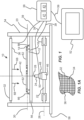
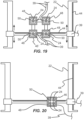
- FIGS. 1-9 show an exemplary embodiment of a microscope imaging system 10 that may include a specimen fixture 12 having an illumination side 14, an imaging side 16 and at least one specimen receptacle 18 as shown in FIG. 5 .
- the specimen receptacle 18 may be disposed in a specimen plane 20 of the specimen fixture 12.
- the microscope imaging system 10 may also include a translation stage 22 which is disposed in fixed relation to the specimen fixture 12 and which faces the imaging side 16 of the specimen fixture 12.
- An objective 24 may be operatively coupled to the translation stage 22, laterally translatable in an x-y plane 26 that is substantially parallel to the specimen plane 20, and include an image input axis 28 disposed towards the imaging side 16 of the specimen fixture 12.
- the objective 24 may also include a object plane 30 which is substantially perpendicular to the image input axis 28 and adjustable to be coplanar with the specimen plane 20.
- embodiments of the objective 24 may include a microscope objective lens with a magnification power of about 10x to about 120x and a working distance of about 0.1 mm to about 10 mm.
- the objective 24 may also include specialized contrast objectives such as a phase contrast microscope objective lens.
- the microscope imaging system embodiment 10 is shown as an "inverted" type system with the objective 24 facing an upward direction, the same or similar arrangement of components of the microscope imaging system 10 could also be used in a non-inverted configuration.
- the microscope imaging system 10 is configured to have the specimens 70, specimen receptacles 18 and specimen fixture 12 disposed in fixed relation to the frame 54 with the objective 24 configured to translate relative thereto, the inverse arrangement could also be used whereby the objective 24 is fixed relative to the frame 54.
- the fixed specimen configuration shown also tends to be more compact.
- An illumination screen 32 may be disposed in fixed relation to the specimen fixture 12.
- the illumination screen 32 may further include an array of light emitting pixels 34 and a flat illumination surface 36 which is substantially parallel to the specimen plane 20.
- the flat illumination surface 36 may be disposed facing the illumination side 14 of the specimen fixture 12.
- a controller 38 may be operatively coupled to the illumination screen 32 and the translation stage 22 with conduits 39 and be configured to coordinate the transmission of an illumination signal to the illumination screen 32 which may be configured to produce emission of a light pattern 40 from the flat illumination surface 36.
- the controller 38 may be configured to coordinate the transmission of a dynamic illumination signal to the illumination screen 32 which produces emission of a light pattern 40 which has a light pattern axis 42 that tracks across the flat illumination surface 36 and remains aligned with the image input axis 28 of the objective 24 as the objective 24 is translated in the x-y plane 26 from a first position to a second position in the x-y plane 26.
- the light pattern axis 42 may be configured as an axis of symmetry of the light pattern 40.
- the light pattern axis 42 may be disposed in the center of the light emitting annular pattern.
- the illumination light 68 that is emitted from the light pattern 40 of the flat illumination surface 36 of the illumination screen 32 propagates at a variety of angles towards the illumination side 14 of the specimen fixture 12.
- the illumination light 68 illuminates the specimen 70 and the specimen plane 20 disposed adjacent the light pattern axis 42 and specimen 70.
- the illumination light, or scattered derivatives thereof, then propagates to the objective 24 and then into the image sensor 50 which may be configured to generate an image signal for display on the display screen 52.
- the conduits 39 that interconnect the controller 38 with the illumination screen 32, translation stage 22, image sensor 50 and display screen 52 discussed below may include any suitable type of conduit configured to transmit energy, information or the like.
- the conduits 39 may include conductive wires, including coaxial cables, fiber optic cables, wireless links or the like.
- Embodiments of the controller 38 may include one or more processors, including microprocessors 41, memory including digital memory 43 and any circuitry or other components such as video cards or the like which may be desirable in order to interconnect and use these or other elements of the controller 38 and microscope imaging system embodiments 10 generally.
- the specimen fixture 12 may include a plurality of specimen receptacles 18.
- the specimen receptacles 18 may be disposed on specimen tray embodiments 62 which are, in turn, disposed on the specimen fixture 12.
- the controller 38 may be configured to coordinate the transmission of an illumination signal to the illumination screen 32 which produces emission of the light pattern 40 from the flat illumination surface 36 which has a light pattern axis 42 that remains aligned with the image input axis 28 of the objective 24 as the objective 24 is translated in the x-y plane 26.
- such tracking of the light pattern axis 42 and image input axis 28 may occur as the objective 24 is being translated from a first position with the image input axis 28 aligned with a first specimen receptacle 18' to a second position with the image input axis 28 aligned with a second specimen receptacle 18" as shown in FIG. 5 .
- the emission of illuminating light 68 may be reduced or eliminated during translation of the objective 24 from the first position 18' to the second position 18" and only activated when the objective 24 is disposed at either the first position 18' or the second position 18".
- the controller 38 may be configured to align the image input axis 28 of the objective 24 with the light pattern axis 42 of the light pattern 40 by mapping positions of the image input axis 28 to corresponding positions on the flat illumination surface 36 of the illumination screen 32.
- the controller 38 may be configured to generate the illumination signal and coordinate the transmission of the illumination signal to the illumination screen.
- the microscope imaging system 10 may further include one or more position sensors 44 operatively coupled to the translation stage 22 and controller 38.
- the position sensors 44 may include optical encoder strips and corresponding readers as shown or any other suitable type of position sensor 44.
- the controller 38 may be configured to receive position information from the position sensor 44 regarding the position of the image input axis 28 of the objective 24 prior to coordinating transmission of the illumination signal to the illumination screen 32.
- the translation stage 22 may be translated by a plurality of servo motors (not shown), stepper motors (not shown) or any other suitable type of motor and the controller 38 may be configured to determine the position of the objective 24 and image input axis 28 by determining the position of each of the motors and optionally accessing a lookup table.
- the translation stage 22 may further include a carrier 46 which is configured to translate in the x-y plane 26 of the translation stage 22 with the objective 24 being secured in fixed relation to the carrier 46 of the translation stage 22.
- a focus mechanism may be configured to adjust the position of the object plane 30 of the objective 24 along the image input axis 28 relative to the specimen plane 20.
- such a focus mechanism may include a z-axis actuator 48 which is operatively coupled between the carrier 46 and the objective 24 and may be configured to adjust the position of the object plane 30 of the objective 24 along the image input axis 28 relative to the specimen plane 20.
- Such z-axis adjustment may also be useful in some instances for keeping illumination light 68 emitted from a light pattern 40 imaged onto a phase contrast ring 78 of a phase contrast objective 24 as discussed in more detail below.
- z-axis translation of the objective 24 relative to the specimen fixture 12 or specimen 70 disposed thereon may be useful in order to focus the objective onto the specimen 70 or portion of interest of the specimen 70.
- z-axis translation of the objective 24 relative to the specimen fixture 12 may also result in relative z-axis translation between the objective 24 and the illumination screen 32.
- phase contrast ring 78 of the phase contrast embodiment of the objective 24 may be made wider in order to accommodate for movement or widening of the image of the light pattern 40 being imaged thereon. This approach, while useful, may also hinder the transmission of illumination light 68 through the objective 24 generally and reduce the brightness of the image.
- Another useful approach to accommodate what would otherwise be relative displacement between the objective 24 and the illumination screen 32 during focusing or any other z-axis translation of the objective 24, may include translating the illumination screen 32 in the z-axis in concert with the z-axis translation of the objective 24.
- one or more motors could be operatively coupled between the frame 54 and the illumination screen 32 and configured to translate the illumination screen 32 by a z-axis displacement that matches z-axis displacement of the objective 24 by virtue of the z-axis actuator 48.
- the illumination screen 32 and objective 24 may be configured to remain stationary relative to each other, and the specimen fixture 12 may be operatively coupled to the frame 54 with one or more motors (not shown) which may serve to translate the specimen fixture 12 in the z-axis along the image input axis 28 of the objective 24.
- the z-axis actuator 48 may include a translation range of up to about 10 mm or more.
- the microscope imaging system 10 may also include an image sensor 50 operatively coupled to the objective 24 and with the controller 38 operatively coupled to the image sensor 50 by conduits 39.
- the image sensor 50 may include a camera, such as a complementary metal-oxide semiconductor (CMOS) camera or a charge-coupled device (CCD) camera.
- CMOS complementary metal-oxide semiconductor
- CCD charge-coupled device
- an optional display screen 52 may be operatively coupled to the controller 38 and be configured to display an image captured by the image sensor 50.
- the display screen 52 may be coupled to the controller 38 by one or more conduits 39.
- the image sensor 50 may be operatively coupled directly to the display screen 52 by one or more conduits 39 (not shown).
- the microscope imaging system 10 may include a rigid frame 54 which is rigidly coupled to a specimen fixture support 56, the illumination screen 32 and translation stage 22.
- the rigid frame 54 may also include a rigid base 58 which has a flat bottom surface and which is disposed at the bottom of the rigid frame 54.
- the rigid frame 54 may be made from any suitable high strength material such as steel, aluminum, composite materials such as carbon fiber or the like.
- the rigid frame 54 may serve as a rigid scaffold in order to prevent relative movement between the specimen fixture 12, the illumination screen 32, and the translation stage 22 as the objective 24 is translated in the x-y plane 26 on a carrier 46 of the translation stage 22.
- the rigid frame 54 is shown having a fairly open configuration, the rigid frame 54 could also be enclosed with adjoining removable flat thin panels covering the front, back and top of the outer perimeter of the rigid frame 54.
- the illumination screen 32 is nominally secured in fixed relation to the specimen fixture 12, in some cases it may be desirable for the illumination screen 32 to be releasably secured to the frame 54 in order to provide access to the specimen fixture in order to place or exchange specimens 70, specimen trays 62 or the like during use. As such, in some cases it may be useful for the illumination screen 32 to be hinged relative to the frame 54 such that one or more sides of the illumination screen 32 can be pivoted clear of the specimen fixture 12 and then easily be returned to its original position parallel to the specimen plane 20 by setting it back down.
- Embodiments of the specimen fixture 12 may include one or more central apertures 60 configured to permit unobstructed imaging of one or more specimen trays 62 disposed thereon while still providing stable support for the specimen trays 62.
- the apertures 60 may be described as central apertures 60, such apertures may be disposed at any suitable location on embodiments of the specimen fixture 12 in order to facilitate imaging of specimens 70 disposed thereon.
- the specimen tray embodiments 62 may each include one or more specimen receptacles 18 which may be configured to hold specimen 70 in a position suitable for microscopic imaging thereof.
- embodiments of the specimen fixture 12 may be configured to position a microscope slide and optional accompanying cover (not shown).
- some specimen tray embodiments 62 include a plurality of specimen receptacles 18 that may be arranged in rows and columns of an array of specimen receptacles 18. In some cases, the specimen tray embodiments 62 may include about 4 specimen receptacles 18 to about 1600 specimen receptacles 18. Common configurations of specimen trays 62 including microtiter trays or plates and the like may include 6, 12, 24, 48, 96, 384 or 1536 specimen receptacles 18 in the form of specimen wells.
- the specimen fixture support 56 which is secured in fixed relation to the frame 54 and which provides mechanical support for the specimen fixture 12 may also include a central aperture 64 to allow unobstructed imaging of the specimen trays 62 disposed on the specimen fixture 12.
- Both the specimen fixture support 56 and specimen fixture 12 may include positioning pins 66 that may be secured to respective illumination surfaces of the specimen fixture support 56 and specimen fixture 12.
- the positioning pins may be configured to laterally secure the specimen trays 62 to the specimen fixture 12 and to laterally secure the specimen fixture 12 to the specimen fixture support 56.
- the positioning pins 66 or any other suitable structure may be configured to define a perimeter that closely fits to an outer lateral surface of the specimen trays 62 or specimen fixture 12.
- the illumination screen 32 may include a pixelated display screen such as a liquid crystal display (LCD) screen, a plasma display screen or the like.
- the flat illumination surface 36 may be configured to emit illumination light 68 from a pixelated structure including about 10 to about 500 pixels per inch.
- the illumination screen 32 may have a brightness of about 100 candelas per square meter to about 800 candelas per square meter.
- the illumination screen 32 may be configured to generate a light pattern 40 with illumination light 68 having an adjustable wavelength of about 400 nm to about 700 nm. Any of the illumination screen embodiments 32 discussed herein may also use any suitable array of alternative light sources such as light emitting diodes (LEDs), vertical cavity surface emitting lasers (VCSELs) or the like.
- LEDs light emitting diodes
- VCSELs vertical cavity surface emitting lasers
- the illumination light 68 emitted therefrom may be polarized or partially polarized.
- the emission of polarized or partially polarized illumination light 68 may have certain benefits, but in other applications, such polarized illumination light 68 may be detrimental to the process.
- Embodiments of such optical layers 67 may include a waveplate or retarder type optical layer 67 that serves to reduce or eliminate the polarization of illumination light embodiments 68 emitted from the flat illumination surface 36 of the illumination screen 32.
- a waveplate or retarder layer may be used to modify the polarization state of the illumination light 68 without reducing the intensity or direction of the illumination light 68.
- Some such optical layer embodiments 67 may serve to rotate linear polarization or transform linear polarization into circular polarization and may include birefringent, crystalline or polymer materials that create a phase shift between polarization components.
- Some specific examples of such optical layers may include 1/4-waveplates, 1/2 waveplates as well as zero order and achromatic waveplates or retarders.
- such an optical layer may be disposed at any position between the sample 70 and the illumination screen 32. For the embodiment shown in FIG. 7A , the optical layer is disposed on the outer surface of the flat illumination surface 36 of the illumination screen 32.
- Some embodiments of a method of microscopic imaging while using microscope imaging system embodiments such as those discussed herein may include aligning the image input axis 28 of the objective 24 at a first position in the specimen plane 20 of the specimen fixture 12 and transmitting a first illumination signal to the illumination screen 32.
- the illumination screen 32 may include the flat illumination surface 36 that faces the illumination side 14 of the specimen fixture 12.
- Illumination light 68 is then emitted from the light pattern 40 of the flat illumination surface 36 of the illumination screen 32 which corresponds to the illumination signal transmitted.
- the light pattern 40 generated by the first illumination signal may be positioned to have a light pattern axis 42 that is aligned with the image input axis 28 of an objective 24.
- the method may further include imaging the specimen plane 20 at the first position 18' (see FIG.
- the objective 24 may be translated in the x-y plane 26 which is parallel with the flat illumination surface 36.
- the objective 24 may be so translated without moving the illumination screen 32 relative to the specimen fixture 12 such that the image input axis 28 of the objective 24 is translated from alignment with the first position 18' in the specimen plane 20 to alignment with a second position 18" in the specimen plane 20.
- a second illumination signal may then be transmitted to the illumination screen 32 and corresponding illumination light 68 emitted from the light pattern 40 of the flat illumination surface 36 of the illumination screen 32 which has a light pattern axis 42 that is aligned with the image input axis 28 of the objective 24 at the second position 18".
- the method may also include imaging the specimen plane 20 at the second position with the objective 24.
- such a method may further include emitting illumination light 68 from the light pattern 40 and maintaining the alignment of the light pattern axis 42 with the image input axis 28 of the objective 24 as the objective 24 is being translated in the x-y plane 26 from the first position 18' to the second position 18" without moving the illumination screen 32 relative to the specimen fixture 12 such that translation of the light pattern axis 42 tracks the translation of the image input axis 28 of the objective 24 by virtue of a dynamic illumination signal that adjusts a position of the light pattern 40 to correspond to an x-y position of the objective 24.
- such a method may further include imaging the specimen 70 or specimen receptacle 18 at the first position 18' in the specimen plane 20 and imaging the specimen 70 or specimen receptacle 18 at the second position 18" in the specimen plane 20.
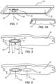
- the objective lens 24 of a microscope imaging system 10 is shown beneath and pointed towards a specimen plane or stage 20 where the object to be imaged or specimen 70 is located.
- Illumination screen 32 is shown with emitted illumination 68 from an annular illumination pattern 40 facing the specimen 70 and microscope objective lens 24.
- Specimen 70 is an object of interest to be imaged.
- a light pattern or shape 40 of an illumination object or zone is being emitted from a flat illumination surface 36 of the illumination screen 32 upon the specimen 70.
- the inverted microscope objective 24 may be translated in the x-y plane 26 and in along a z-axis beneath the specimen plane 20 which is trans-illuminated from above by the illumination light pattern 40.
- Embodiments discussed herein may include the use of a flat illumination surface 36 of a standard computer monitor or TV display such as the illumination screen 32 as a method of displaying illumination patterns 40 and emitting corresponding illumination light patterns 40 for increased contrast used for microscopy and the like.
- FIG. 11 the objective 24 is shown moving relative to the specimen plane 20 by the arrow 74 in FIG. 11 .
- the illumination light pattern 40 is also shown moving across the flat illumination surface 36 of the illumination screen 32 in corresponding displacement to remain in alignment with the objective 24.
- FIG. 12 shows a specimen 70 being tracked by keeping it in the center of the field of view of the objective 24 automatically, and the illumination light pattern 40 may be maintained in alignment with the corresponding objective 24 as indicated by arrows 76.
- FIG. 13 illustrates an illumination light pattern 40 that may change position over time while the objective 24 images the specimen plane 20. In some instances, this technique may yield information on a 3-dimensional shape of the specimen 70.
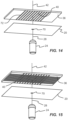
- the illumination light pattern 40 may include a regularly repeating intensity variation 72 of a light pattern 40 in one dimension both stationary and sweeping across the specimen plane 20 as shown in FIG. 14 . In some cases, the illumination light pattern 40 may include a regularly repeating intensity variation in multiple dimensions both stationary and sweeping across the specimen plane 20 as shown in FIG. 15 .
- microscope imaging system embodiments 10, 10' may be directed generally to transmitted and oblique-illumination sources for microscope imaging or any other suitable form of imaging.
- the quality of images generated from the objective 24 and image sensor 50 may vary depending upon changes in the direction from which illumination 68 arrives, and from changes in the pattern of the illumination light 68.
- a display screen 32 it may be possible to emit illuminating light 68 from a range of directions and in a variety of patterns. This makes possible manual or automated searches for optimal images by altering the direction and pattern of the illuminating light 68 and analyzing the images using software running on a computer such as processor 41.
- Some microscope imaging system embodiments 10, 10' discussed herein may be directed to methods and devices for the use of a TV or monitor and its graphical display as a flexible illumination screen 32 with positional, multicolored, patterned, and dynamic display as bright field or transmitted illumination for enhanced contrast.
- the large format of display screen embodiment 32 including projector embodiments may allow the positions of multiple specimens 70 to be illuminated by emitting illuminating light 68 from certain portions of a flat illumination screen 36 of a display screen 32 without physical movement or replication of an overhead light fixture.
- the use of a planar illumination screen 32 for an illumination source allows a variety of shapes and patterns on such a screen to be optimized for the transmitted light pattern 40.
- the addition of an optional lens array or shade array (not shown) to manipulate the displayed light patterns 40 and illumination source into desired optical properties is contemplated herein as well.
- microscope imaging system and method embodiments 10, 10' discussed herein may also be directed to methods and devices for the use of a projector and its associated projected graphics and light patterns 40 as a flexible illumination source with positional, multicolored, patterned, and dynamic display as bright field or transmitted illumination for enhanced contrast.
- Embodiments discussed herein are also directed to methods and devices for the automatic optimization of image quality based on feedback from a live image, such as may be generated by the image sensor 50.
- phase contrast microscopy By using a sufficiently large display screen 32 positioned so its output light 68 reaches a specimen 70 and then enters the objective lens 24 of a microscope, it is possible to cause an image to appear on the flat illumination surface 36 of the illumination screen 32 such that if the displayed light pattern 40 is of appropriate shape, color, and intensity, that image can serve as a light source for the microscope.
- phase contrast microscopy it is possible to cause to appear on the display screen 32 an annulus of particular angular shape with reference to the center of the object field or image input axis 28 of a phase contrast objective lens, such that a phase contrast image is generated.
- a light pattern 40 having an annular configuration displayed may be manually or automatically aligned with a corresponding image input axis 28 of the objective lens 24.
- software running on a computer that receives images from the image sensor 50 in the microscope imaging system 10, 10' may execute an algorithm that calculates the optimum position and shape of the light pattern annulus 40 displayed by analyzing the images and altering the annulus configuration.
- Some microscope imaging system embodiments 10, 10' discussed here may greatly simplify a hardware configuration as a single illumination screen 32 may be used as the light source hardware. No lenses or masks need to be used in many cases. Embodiments may also include the use of a sufficiently large illumination screen 32 such that it may be possible to position the output light 68 as needed for imaging a large area. This may make it possible to use a simpler design of an imaging system 10, 10' wherein the specimen(s) 70 remain stationary and the imaging optics such as the objective 24 move to scan an area. Using software control, only the patterns of illuminating light 68 emitted from the illumination screen 32 need to be moved or otherwise translated. The illumination screen 32 itself may be stationary, so there are no physical parts that need be moved to maintain illumination alignment with the imaging optics 24.
- the display may include a low profile, i.e., small height, making this highly advantageous in live cell imaging in incubators. Because the illumination screen 32 may be homogenous in light produced, variability across labware may be less in some cases. In some instances, for the microscope imaging system embodiments 10, 10' discussed herein, a vertical separation distance between the flat illumination surface 36 of the illumination screen 32 and the specimen plane 20 of the specimen fixture 12 may be about 5 cm to about 35 cm.
- Some microscope imaging system embodiments 10, 10' discussed herein may include automation of alignment of the light pattern axis 42 of the output light pattern(s) with the image input axis 28 of the objective lens(es) 24.
- the output light 68 may also be optimized in some cases to provide a means of discovering new light patterns 40 which produce contrast.
- Arbitrary and variable shapes and colors of light may be used in a manual or automated search for the illumination condition that provides valuable images.
- Light patterns 40 may include bullseyes, checkerboards, half-moons, pinpoints, boxes, crosshairs, circles, squares, polygons, freehand lasso, pie chart rays and the like.
- Some embodiments 10, 10' discussed herein may also include the display of a phase annulus 40 and its size, position and thickness may be adjusted and optimized, including dynamically.
- microscope imaging system embodiments 10, 10' discussed herein may also include single or multiple images acquired with structured light patterns 40 that may be used in combination with mathematical image analysis techniques to extract information about specimens 70. This may include the ability to orbit, raster, or spiral a small symmetrical spot of light around the field of view (FOV) while sequential images may be taken for enhanced 3-D imaging, DOF imaging, ptychography imaging and the like.
- Embodiments 10, 10' discussed herein may also include using the color of the display to optimize an imaging experiment. Using green to maximize detection by image sensor 50 and red to reduce the energy of the illumination, for example.
- embodiments 10, 10' discussed herein may also include the ability to reduce the energy of the illumination light 68 by pulsing the illumination light 68 at the frame rate or some offset. Sample lensing or general matrix effects may also be compensated for in some cases in order to flatten the image brightness by displaying or projecting a compensatory image light pattern 40. In some instances, illumination conditions may be stored in memory 43 and retrieved by the processor 41 to reduce the effort needed to acquire new images. Embodiments 10, 10' discussed herein may also include the ability to function over a range of distances from the objective lens 24 because the light patterns 40 may be scaled to control their angular size. This makes some embodiments useful for both robotic applications that require large operating clearance and incubator applications that require a compact system 10, 10'.
- the illumination screen 32 may also be used in some instances to provide an overhead shroud for fluorescence microscopy; shielding room light, protecting people's eyes from UV, etc.
- Embodiments discussed herein may also include shade arrays with and without lenses- honeycomb dimensional grid for limiting projection angles used in conjunction with a lens.
- Embodiments discussed herein may also include a variety of lenses, including ball lenses, concave lenses, convex lenses, Fresnel lenses, polarized lenses, reducing lenses, expanding lenses, directional lenses, and the like.
- an illumination light pattern 40 from an illumination screen may be used to effect biological and chemical mechanisms- photocaged compounds, photolysis, optogenetics, and optical chemical synthesis.
- Embodiments discussed herein may also include using the illumination light pattern 40 as an attractant or deterrent to a biological response.
- the illumination screen 32 may include an LCD, CRT, TFT, retinal display, DLP, LED, OLED type illumination screen 32 or the like.
- the illumination screen 32 may be of sufficient dimensions such that it emits light of one or more colors positioned so that the emitted light enters the objective lens 24.
- the displayed illumination light 68 may be adjusted, including adjustment of the color of the illumination light 68, adjustment of the position of the light pattern 40 on the flat illumination screen 36, and adjustment of the time dependence of the illumination light 68.
- 10' a light pattern image 40 may be used in feedback to optimize the illumination including automatically.
- One exemplary light pattern 40 may include a single circle of light centered above the objective 24 for "aperture illumination" with the center of the circle of light pattern 40 or light pattern axis 42 being aligned with the image input axis 28 of the objective 24.
- a plurality of microscope objectives 24 may be illuminated sequentially or simultaneously.
- many positions of a single microscope objective 24 may be illuminated sequentially or simultaneously.
- a plurality of microscope objectives 24 which are too close together may have individual illumination sources that include respective overlapping illumination light patterns 40 projected sequentially.
- Embodiments of the electronic image sensor 50 may be used for forming a system of sufficient sensitivity that permits transmission of the images to a computer including the controller 38 or components of a computer such a the microprocessor 41.
- Software running on the computer or microprocessor 41 of the controller 38 may be configured to control the illumination screen 32 and access the images from the same image sensor 50.
- Embodiments of the microscope imaging system 10, 10' may include an objective lens 24 of a type designed to generate any of bright field images, dark field images, phase contrast images, or other enhanced images.
- phase contrast system In a phase contrast system generally, the image of an annulus of light is projected at optical infinity by passing the light 68 through a condenser lens (not shown). This light illuminates the specimen 70. The fraction of this light 68 that passes through the specimen 70 without deviation enters a phase contrast type objective 24. Such objectives are designed to focus this light 68 onto an internal phase ring. This may be useful in order to achieve the phase contrast effect. If an annular light source is used to illuminate a specimen 70 without a special phase contrast objective lens then its image may not projected at infinity and the undeviated light will not be focused on the phase ring inside the objective. In some cases, this may degrade the phase contrast effect.
- phase contrast effect may generally be improved or restored by designing a special phase contrast objective lens 24 which is configured to focus an image of the annulus of light onto the internal phase ring of a phase contrast objective for the case of an annular light source that is positioned at some known distance from the objective, without an interposed lens as in the standard phase contrast system.
- FIG. 16 is a schematic representation of an objective 24 that is configured as a typical phase contrast type objective including a phase ring 78 disposed within the objective optical train.
- the phase ring 78 is represented by two schematic cross section segments.
- the objective is disposed below a specimen 70 which is being illuminated by an annular light pattern 40 represented by two schematic cross section segments of the annular light pattern 40.
- a phase contrast microscopy configuration would include a condenser lens (not shown) aligned with the optical axis of the system and disposed between the annular light pattern 40 and the specimen 70.
- Such a condenser lens would typically be configured to correct the angle of the illumination light 68 emitted from the light pattern 40 so as to effectively present the light pattern 40 at a distance of infinity from the objective 24 and specimen 70.
- the light pattern 40 would be imaged by the objective lens 79 onto the phase ring 78 disposed within the objective so as to yield a high degree of phase contrast for the image generated by the phase contrast objective 24.
- such a condenser lens may be inconvenient to include and position in such a system, particularly such a system wherein it may be desirable to translate the objective 24 relative to the specimen 70.
- the light pattern 40 is not properly imaged onto the phase ring 78 as indicated by the displacement of the point of intersection 80 of the rays of illumination light 68 being positioned below the phase ring 78 within the objective 24.
- Such an arrangement may not be effective to produce a useful amount of phase contrast during use.
- a special phase contrast objective 24 may be used that includes an objective lens 79' (and any other associated optics required to achieve the desired result) that is configured to image the light pattern 40 onto the phase ring 78 without the use of a condenser lens and with a light pattern 40 that is not effectively positioned at a distance of infinity from the objective 24 and specimen 70.
- FIG. 17 shows a schematic representation of an objective 24 disposed below a specimen 70 which is being illuminated by an annular light pattern 40 similar to the arrangement of FIG. 16 .
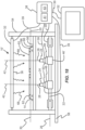
- a microscope imaging system 10 may include the specimen fixture 12 having the illumination side 14, the imaging side 16 and specimen receptacle 18 which is disposed in the specimen plane 20 of the specimen fixture 12.
- the illumination screen 32 may be disposed in fixed relation to the specimen fixture 12 facing the illumination side 14 of the specimen fixture 12, and include a flat illumination surface 36 that is configured to emit an annular light pattern 40 having a light pattern axis 42.
- the microscope imaging system 10 may also include a phase contrast objective 24 which faces the imaging side 16 of the specimen fixture 12, which includes the image input axis 28 that is aligned with the light pattern axis 42, and which is configured to form an image of an annular light pattern 42 of the illumination screen onto a phase ring 78 of the phase contrast objective 24 without the use of a condenser lens (not shown) disposed between the illumination screen 32 and the specimen plane 20 and with the annular light pattern 40 of the illumination screen 32 not being effectively disposed at infinity with respect to the phase contrast objective 24.
- a phase contrast objective 24 which faces the imaging side 16 of the specimen fixture 12, which includes the image input axis 28 that is aligned with the light pattern axis 42, and which is configured to form an image of an annular light pattern 42 of the illumination screen onto a phase ring 78 of the phase contrast objective 24 without the use of a condenser lens (not shown) disposed between the illumination screen 32 and the specimen plane 20 and with the annular light pattern 40 of the illumination screen 32 not
- the microscope imaging system 10 may further include the translation stage 22 which is disposed in fixed relation to the specimen fixture 12 and which faces the imaging side 16 of the specimen fixture 12.
- the phase contrast objective 24 may be operatively coupled to the translation stage 22 and be laterally translatable in the x-y plane 26, the x-y plane 26 being substantially parallel to the specimen plane 20 in some cases.
- Such a microscope imaging system embodiment 10 may further include the controller 38 which is operatively coupled to the illumination screen 32 and the translation stage 22 and be configured to coordinate the transmission of an illumination signal to the illumination screen 32 which produces emission of the annular light pattern 40 from the flat illumination surface 36.
- the annular light pattern 40 may include a light pattern axis 42 that remains aligned with the specimen receptacle 18 and the image input axis 28 of the phase contrast objective 24 as the phase contrast objective 24 is translated in the x-y plane 26 from a first position to a second position.
- the controller 38 may be configured to align the image input axis 28 of the phase contrast objective 24 with the light pattern axis 42 by mapping positions of the image input axis 28 to corresponding positions on the flat illumination surface 36 of the illumination screen 32.
- the translation stage 22 further includes a carrier 46 which may be configured to translate in the x-y plane 26 and the phase contrast objective 24 may be secured in fixed relation to the carrier 46 of the translation stage 22.
- a focus mechanism may be configured to adjust the position of an object plane of the phase contrast objective 24 along the image input axis 28 relative to the specimen plane 20.
- the focus mechanism may include the z-axis actuator 48 which may be operatively coupled between the carrier 46 and the phase contrast objective 24 and may be configured to adjust the position of the object plane of the phase contrast objective 24 along the image input axis 28 relative to the specimen plane 20.
- such a system may include a plurality of phase contrast objectives 24.
- any of the microscope imaging system and method embodiments discussed herein may include a plurality of objectives 24 in order to provide alternative contrast enhancement capabilities or for any other suitable purpose.
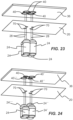
- some microscope imaging system embodiments 10' may include a plurality of objectives 24 which are operatively coupled to the translation stage 22 on the imaging side 16 of the specimen fixture 12, which are laterally translatable in the x-y plane 26 that is substantially parallel to the specimen plane 20, which each include an image input axis 28 disposed towards the imaging side 16 of the specimen fixture 12 and which each include an imaging plane or object plane 30 which is substantially perpendicular to the image input axis 28 and that may be adjusted along a z-axis of the objective 24 to be coplanar with the specimen plane 20.
- An image sensor 50 operatively coupled to each of the respective objectives 24 with the plurality of objectives 24.
- the plurality of objectives 24 may be secured in fixed relation relative to each other in the x-y plane 26.
- the plurality of objectives 24 may be each translatable in the x-y plane 26 independent of each other.
- a plurality of objectives 24 may be used to image a plurality of corresponding specimens 70 using a plurality of illumination light patterns 40 aligned with each respective microscope objective 24.
- sequential illumination may be included in order to avoid interference from adjacent patterns of illumination 40.
- the microscope objectives 24 may be of different types, and the illumination light patterns 40, 40', 40" and 40′′′ shown in FIG. 24 may be different and appropriate for each respective objective 24.
- Illumination light patterns 40, 40', 40" and 40′′′ may be any shape from a pinpoint to an infinite plane which may include the entire flat illumination surface 36 of the illumination screen 32.
- a plurality of objectives 24 may be moved relative to the specimen plane 20 and the corresponding illumination light patterns 40 remain aligned with the image input axes 28 of the respective objectives 24 as shown in FIG. 25 .
- Embodiments illustratively described herein suitably may be practiced in the absence of any element(s) not specifically disclosed herein.
- any of the terms “comprising,” “consisting essentially of,” and “consisting of' may be replaced with either of the other two terms.
- the terms and expressions which have been employed are used as terms of description and not of limitation and use of such terms and expressions do not exclude any equivalents of the features shown and described or portions thereof, and various modifications are possible.
- a or “an” can refer to one of or a plurality of the elements it modifies (e.g., "a reagent” can mean one or more reagents) unless it is contextually clear either one of the elements or more than one of the elements is described.
Landscapes
- Physics & Mathematics (AREA)
- Chemical & Material Sciences (AREA)
- Analytical Chemistry (AREA)
- General Physics & Mathematics (AREA)
- Optics & Photonics (AREA)
- Engineering & Computer Science (AREA)
- Multimedia (AREA)
- Computer Vision & Pattern Recognition (AREA)
- Microscoopes, Condenser (AREA)
Claims (14)
- Mikroskopbildgebungssystem (10), umfassend:eine Probenhalterung (12), umfassend eine Beleuchtungsseite (14), eine Bildgebungsseite (16) und mindestens eine Probenaufnahme (18), die in einer Probenebene (20) der Probenhalterung (12) angeordnet ist;eine Verschiebungseinrichtung (22), die in fester Beziehung zu der Probenhalterung (12) angeordnet ist und die der Bildgebungsseite (16) der Probenhalterung (12) zugewandt ist;ein Objektiv (24), das betriebsfähig mit der Verschiebungseinrichtung (22) gekoppelt ist, das lateral in einer x-y-Ebene (26) verschiebbar ist, die im Wesentlichen parallel zu der Probenebene (20) ist, das eine Bildeingangsachse (28), angeordnet zu der Bildgebungsseite (16) der Probenhalterung (12), beinhaltet und das eine Objektebene (30) beinhaltet, die im Wesentlichen senkrecht zu der Bildeingangsachse (28) ist und dafür einstellbar ist, mit der Probenebene (20) komplanar zu sein;einen Beleuchtungsbildschirm (32), angeordnet in fester Beziehung zu der Probenhalterung (12), wobei der Beleuchtungsbildschirm (32) ein Array von lichtemittierenden Pixeln (34) und eine flache Beleuchtungsfläche (36) beinhaltet, die im Wesentlichen parallel zu der Probenebene (20) angeordnet ist und die der Beleuchtungsseite (14) der Probenhalterung (12) zugewandt ist; undeinen Controller (38), der betriebsfähig mit dem Beleuchtungsbildschirm (32) und der Verschiebungseinrichtung (22) gekoppelt ist und der dafür ausgelegt ist, Transmission eines Beleuchtungssignals mit dem Beleuchtungsbildschirm (32) zu koordinieren, der Emission eines Lichtmusters (40) von der flachen Beleuchtungsfläche (36), das eine Lichtmusterachse (42) aufweist, produziert, wobei die Lichtmusterachse (42) eine Symmetrieachse des Lichtmusters (40) umfasst, die mit der Bildeingangsachse (28) des Objektivs (24) ausgerichtet bleibt, wenn das Objektiv (24) in der x-y-Ebene (26) aus einer ersten Position in eine zweite Position verschoben wird.
- Mikroskopbildgebungssystem (10) nach Anspruch 1, wobei die Probenhalterung (12) eine Vielzahl von Probenaufnahmen (18) umfasst und der Controller (38) dafür ausgelegt ist, Transmission des Beleuchtungssignals mit dem Beleuchtungsbildschirm (32) zu koordinieren, der Emission des Lichtmusters (40) von der flachen Beleuchtungsfläche (36) produziert, die die Lichtmusterachse (42) aufweist, die mit der Bildeingangsachse (28) des Objektivs (24) ausgerichtet bleibt, wenn das Objektiv (24) in der x-y-Ebene (26) verschoben wird aus einer ersten Position, mit der Bildeingangsachse (28) mit einer ersten Probenaufnahme (18) ausgerichtet, in eine zweite Position, mit der Bildeingangsachse (28) mit einer zweiten Probenaufnahme (18) ausgerichtet.
- Mikroskopbildgebungssystem (10) nach Anspruch 1, wobei der Controller (38) ausgelegt ist zum Ausrichten der Bildeingangsachse (28) des Objektivs (24) mit der Lichtmusterachse (42) des Lichtmusters (40), indem Positionen der Bildeingangsachse (28) korrespondierenden Positionen auf der flachen Beleuchtungsfläche (36) des Beleuchtungsbildschirms (32) zugeordnet werden.
- Mikroskopbildgebungssystem (10) nach Anspruch 1, wobei der Controller (38) ausgelegt ist zum Erzeugen des Beleuchtungssignals und zum Koordinieren von Transmission des Beleuchtungssignals mit dem Beleuchtungsbildschirm (32).
- Mikroskopbildgebungssystem (10) nach Anspruch 1, ferner umfassend einen Positionssensor (44), betriebsfähig mit der Verschiebungseinrichtung (22) und dem Controller (38) gekoppelt, und wobei der Controller (38) ausgelegt ist zum Empfangen von Positionsinformationen von dem Positionssensor (44) hinsichtlich einer Position der Bildeingangsachse (28) des Objektivs (24) vor Koordinieren der Transmission des Beleuchtungssignals mit dem Beleuchtungsbildschirm (32).
- Mikroskopbildgebungssystem (10) nach Anspruch 1, wobei die Verschiebungseinrichtung (22) ferner einen Träger (46) beinhaltet, der ausgelegt ist zum Verschieben in der x-y-Ebene (26), und wobei das Objektiv (24) in einer festen Beziehung mit dem Träger (46) der Verschiebungseinrichtung (22) gesichert ist.
- Mikroskopbildgebungssystem (10) nach Anspruch 1, ferner umfassend einen Bildsensor (50), betriebsfähig mit dem Objektiv (24) gekoppelt.
- Mikroskopbildgebungssystem (10) nach Anspruch 7, wobei der Controller (38) betriebsfähig mit dem Bildsensor (50) gekoppelt ist.
- Mikroskopbildgebungssystem (10) nach Anspruch 1, wobei das Objektiv (24) eine Phasenkontrastmikroskop-Objektivlinse (24) umfasst.
- Mikroskopbildgebungssystem (10) nach Anspruch 1, ferner umfassend eine Vielzahl von Objektiven (24), die betriebsfähig mit der Verschiebungseinrichtung (22) auf der Bildgebungsseite (16) der Probenhalterung (12) gekoppelt sind, die lateral in der x-y-Ebene (26) verschiebbar sind, die im Wesentlichen parallel zu der Probenebene (20) ist, die jeweils eine Bildeingangsachse (28), angeordnet zu der Bildgebungsseite (16) der Probenhalterung (12), beinhalten und die jeweils eine Objektebene (30) beinhalten, die im Wesentlichen senkrecht zu der Bildeingangsachse (28) ist und die entlang einer z-Achse eingestellt werden kann, um mit der Probenebene (20) komplanar zu sein; und
einen Bildsensor (50), jeweils betriebsfähig mit jedem Objektiv (24) aus der Vielzahl von Objektiven (24) gekoppelt. - Mikroskopbildgebungssystem (10) nach Anspruch 10, wobei die Vielzahl von Objektiven (24) in der x-y-Ebene (26) relativ zueinander in fester Beziehung gesichert sind.
- Mikroskopbildgebungssystem (10) nach Anspruch 11, wobei die Vielzahl von Objektiven (24) jeweils in der x-y-Ebene (26) unabhängig voneinander verschiebbar sind.
- Mikroskopbildgebungssystem (10) nach Anspruch 1, wobei der Beleuchtungsbildschirm (32) einen Flüssigkristall-Anzeigebildschirm (52) umfasst.
- Mikroskopbildgebungssystem (10) nach Anspruch 1, wobei der Beleuchtungsbildschirm (32) einen Plasma-Anzeigebildschirm (52) umfasst.
Applications Claiming Priority (2)
| Application Number | Priority Date | Filing Date | Title |
|---|---|---|---|
| US201862724579P | 2018-08-29 | 2018-08-29 | |
| PCT/US2019/048582 WO2020047105A1 (en) | 2018-08-29 | 2019-08-28 | Illumination display as illumination source for microscopy |
Publications (3)
| Publication Number | Publication Date |
|---|---|
| EP3844550A1 EP3844550A1 (de) | 2021-07-07 |
| EP3844550A4 EP3844550A4 (de) | 2022-06-22 |
| EP3844550B1 true EP3844550B1 (de) | 2024-10-30 |
Family
ID=69645359
Family Applications (1)
| Application Number | Title | Priority Date | Filing Date |
|---|---|---|---|
| EP19854771.3A Active EP3844550B1 (de) | 2018-08-29 | 2019-08-28 | Beleuchtungsanzeige als beleuchtungsquelle für mikroskopie |
Country Status (4)
| Country | Link |
|---|---|
| US (2) | US11740447B2 (de) |
| EP (1) | EP3844550B1 (de) |
| CN (1) | CN112912781B (de) |
| WO (1) | WO2020047105A1 (de) |
Families Citing this family (6)
| Publication number | Priority date | Publication date | Assignee | Title |
|---|---|---|---|---|
| CN112912781B (zh) * | 2018-08-29 | 2022-11-29 | 艾塔鲁玛公司 | 作为用于显微术的照明源的照明显示器 |
| CN111812833A (zh) * | 2020-08-04 | 2020-10-23 | 东南大学江北新区创新研究院 | 一种用于器官芯片成像的低扰动显微镜及其成像方法 |
| US12184037B2 (en) * | 2020-08-19 | 2024-12-31 | Li-Cor Biotech, Llc | Multi-modal imaging systems and methods |
| KR102596730B1 (ko) * | 2022-02-16 | 2023-11-02 | 주식회사 팍스웰 | 렌즈없는 광학 시스템 |
| JP2024008247A (ja) * | 2022-07-07 | 2024-01-19 | 株式会社エビデント | 観察システム、観察装置 |
| CN115222817B (zh) * | 2022-08-31 | 2022-11-29 | 成都千嘉科技股份有限公司 | 一种指针式压力表的指针定位方法 |
Family Cites Families (28)
| Publication number | Priority date | Publication date | Assignee | Title |
|---|---|---|---|---|
| JPH07122694B2 (ja) * | 1986-10-16 | 1995-12-25 | オリンパス光学工業株式会社 | 顕微鏡用照明装置 |
| US4948258A (en) | 1988-06-27 | 1990-08-14 | Harbor Branch Oceanographic Institute, Inc. | Structured illumination surface profiling and ranging systems and methods |
| US5239178A (en) * | 1990-11-10 | 1993-08-24 | Carl Zeiss | Optical device with an illuminating grid and detector grid arranged confocally to an object |
| DE4231406A1 (de) | 1992-09-19 | 1994-03-24 | Leica Mikroskopie & Syst | Hellfeld-Durchlicht-Beleuchtungseinrichtung für Mikroskope |
| ATE481637T1 (de) * | 1998-08-28 | 2010-10-15 | Febit Holding Gmbh | Verfahren zur herstellung von biochemischen reaktionsträgern |
| US6704447B2 (en) | 2001-02-21 | 2004-03-09 | Justsystem Corporation | Method and apparatus for using illumination from a display for computer vision based user interfaces and biometric authentication |
| DE10119615A1 (de) * | 2001-04-21 | 2002-10-24 | Techno Trans Ges Zur Foerderun | Verfahren und Einrichtung zur medizinischen Befundung der Mikrozirkulation mit Hilfe eines Video-Kapillar-Mikroskops |
| WO2004070653A2 (en) * | 2003-01-31 | 2004-08-19 | Discovery Partners International | Image analysis system and method |
| US7663691B2 (en) | 2005-10-11 | 2010-02-16 | Apple Inc. | Image capture using display device as light source |
| WO2007109678A2 (en) | 2006-03-20 | 2007-09-27 | Baylor College Of Medicine | Method and system for non-contact fluorescence optical tomography with patterned illumination |
| US8279329B2 (en) | 2007-04-10 | 2012-10-02 | University Of Rochester | Structured illumination for imaging of stationary and non-stationary, fluorescent and non-fluorescent, objects |
| US8089691B2 (en) | 2007-12-10 | 2012-01-03 | Quorum Technologies Inc. | Projection device for patterned illumination and microscopy |
| JP5200642B2 (ja) * | 2008-04-15 | 2013-06-05 | ソニー株式会社 | 画像表示装置及び画像表示方法 |
| WO2010105015A2 (en) * | 2009-03-11 | 2010-09-16 | The University Of North Carolina At Chapel Hill | Methods, systems, and computer readable media for microscopy tracking |
| CN102116927B (zh) * | 2009-12-31 | 2013-04-24 | 麦克奥迪实业集团有限公司 | 显微镜总放大倍数的显示装置 |
| US9494783B2 (en) | 2010-11-30 | 2016-11-15 | Etaluma Inc. | Compact, high-resolution fluorescence and brightfield microscope and methods of use |
| US9069175B2 (en) | 2011-04-08 | 2015-06-30 | Kairos Instruments, Llc | Adaptive phase contrast microscope |
| JP5690359B2 (ja) * | 2012-03-30 | 2015-03-25 | 株式会社Screenホールディングス | 撮像装置および撮像方法 |
| US9443310B2 (en) | 2013-10-09 | 2016-09-13 | Microsoft Technology Licensing, Llc | Illumination modules that emit structured light |
| US9453995B2 (en) * | 2013-12-03 | 2016-09-27 | Lloyd Douglas Clark | Electronically variable illumination filter for microscopy |
| CN103852878B (zh) * | 2014-01-08 | 2016-05-25 | 麦克奥迪实业集团有限公司 | 一种具有实时聚焦的显微切片快速数字扫描装置及其方法 |
| US20160202460A1 (en) | 2015-01-13 | 2016-07-14 | University Of Connecticut | 3D Microscopy With Illumination Engineering |
| US10502942B2 (en) * | 2015-06-12 | 2019-12-10 | Techshot, Inc. | Integrated illuminator and condenser for microscopes |
| CN105158888B (zh) | 2015-09-29 | 2020-09-11 | 南京理工大学 | 基于lcd液晶面板的可编程显微镜聚光镜装置及其成像方法 |
| CN105158894A (zh) * | 2015-09-29 | 2015-12-16 | 南京理工大学 | 基于彩色led阵列照明的无透镜相位显微层析装置及图像重构方法 |
| CN105158887B (zh) * | 2015-09-29 | 2017-09-22 | 南京理工大学 | 基于可编程led阵列照明的多模式显微成像方法 |
| DE102016117675B4 (de) * | 2016-09-20 | 2018-07-05 | Leica Microsystems Cms Gmbh | Mikroskop mit einem Beleuchtungsmodul |
| CN112912781B (zh) * | 2018-08-29 | 2022-11-29 | 艾塔鲁玛公司 | 作为用于显微术的照明源的照明显示器 |
-
2019
- 2019-08-28 CN CN201980055777.9A patent/CN112912781B/zh active Active
- 2019-08-28 US US16/976,331 patent/US11740447B2/en active Active
- 2019-08-28 WO PCT/US2019/048582 patent/WO2020047105A1/en not_active Ceased
- 2019-08-28 EP EP19854771.3A patent/EP3844550B1/de active Active
-
2023
- 2023-07-10 US US18/220,184 patent/US20230350182A1/en active Pending
Also Published As
| Publication number | Publication date |
|---|---|
| US20230350182A1 (en) | 2023-11-02 |
| US11740447B2 (en) | 2023-08-29 |
| WO2020047105A1 (en) | 2020-03-05 |
| EP3844550A1 (de) | 2021-07-07 |
| CN112912781A (zh) | 2021-06-04 |
| EP3844550A4 (de) | 2022-06-22 |
| US20210141203A1 (en) | 2021-05-13 |
| CN112912781B (zh) | 2022-11-29 |
Similar Documents
| Publication | Publication Date | Title |
|---|---|---|
| EP3844550B1 (de) | Beleuchtungsanzeige als beleuchtungsquelle für mikroskopie | |
| AU2003238484B2 (en) | Microscope with a viewing direction perpendicular to the illumination direction | |
| CN107526156B (zh) | 光片显微镜以及用于运行光片显微镜的方法 | |
| US7312432B2 (en) | Single axis illumination for multi-axis imaging system | |
| JP7167276B2 (ja) | 二重光学経路および単一撮像センサを使用した低解像度スライド撮像、スライドラベル撮像および高解像度スライド撮像 | |
| JP6798990B2 (ja) | 線走査、標本走査、多モード共焦点顕微鏡 | |
| JP6972188B2 (ja) | 異なるサイズのスライド用の調整可能なスライドステージ | |
| JP6940696B2 (ja) | 二次元および三次元の固定式z走査 | |
| JP7021348B2 (ja) | カルーセルの回転を不能にするセーフティライトカーテン | |
| KR20200041983A (ko) | 실시간 오토포커스 포커싱 알고리즘 | |
| JP7004808B2 (ja) | スライドガラスの走査および処理のための対向縁部システム | |
| JP6869435B2 (ja) | スライドラックカルーセル | |
| KR101650138B1 (ko) | 다중 표면 검사 시스템 및 방법 | |
| JP6952891B2 (ja) | 2×3および1×3スライド用のカルーセル | |
| CN111812833A (zh) | 一种用于器官芯片成像的低扰动显微镜及其成像方法 | |
| JP2020046670A (ja) | 調整可能な角度付照明を備えたハイスループット光シート顕微鏡 | |
| AU2023377810A1 (en) | Non-invasive imaging system for imaging biological materials | |
| HK1237043B (zh) | 线扫描、样品扫描、多模式共聚焦显微镜 |
Legal Events
| Date | Code | Title | Description |
|---|---|---|---|
| STAA | Information on the status of an ep patent application or granted ep patent |
Free format text: STATUS: THE INTERNATIONAL PUBLICATION HAS BEEN MADE |
|
| STAA | Information on the status of an ep patent application or granted ep patent |
Free format text: STATUS: REQUEST FOR EXAMINATION WAS MADE |
|
| PUAI | Public reference made under article 153(3) epc to a published international application that has entered the european phase |
Free format text: ORIGINAL CODE: 0009012 |
|
| 17P | Request for examination filed |
Effective date: 20210326 |
|
| AK | Designated contracting states |
Kind code of ref document: A1 Designated state(s): AL AT BE BG CH CY CZ DE DK EE ES FI FR GB GR HR HU IE IS IT LI LT LU LV MC MK MT NL NO PL PT RO RS SE SI SK SM TR |
|
| DAV | Request for validation of the european patent (deleted) | ||
| DAX | Request for extension of the european patent (deleted) | ||
| A4 | Supplementary search report drawn up and despatched |
Effective date: 20220524 |
|
| RIC1 | Information provided on ipc code assigned before grant |
Ipc: G02B 21/26 20060101ALI20220518BHEP Ipc: G02B 21/18 20060101ALI20220518BHEP Ipc: G02B 21/14 20060101ALI20220518BHEP Ipc: G01N 21/63 20060101ALI20220518BHEP Ipc: G01N 21/62 20060101ALI20220518BHEP Ipc: G01N 21/00 20060101ALI20220518BHEP Ipc: G02B 21/36 20060101ALI20220518BHEP Ipc: G02B 21/00 20060101AFI20220518BHEP |
|
| GRAP | Despatch of communication of intention to grant a patent |
Free format text: ORIGINAL CODE: EPIDOSNIGR1 |
|
| STAA | Information on the status of an ep patent application or granted ep patent |
Free format text: STATUS: GRANT OF PATENT IS INTENDED |
|
| INTG | Intention to grant announced |
Effective date: 20240620 |
|
| GRAS | Grant fee paid |
Free format text: ORIGINAL CODE: EPIDOSNIGR3 |
|
| P01 | Opt-out of the competence of the unified patent court (upc) registered |
Free format text: CASE NUMBER: APP_47217/2024 Effective date: 20240815 |
|
| GRAA | (expected) grant |
Free format text: ORIGINAL CODE: 0009210 |
|
| STAA | Information on the status of an ep patent application or granted ep patent |
Free format text: STATUS: THE PATENT HAS BEEN GRANTED |
|
| AK | Designated contracting states |
Kind code of ref document: B1 Designated state(s): AL AT BE BG CH CY CZ DE DK EE ES FI FR GB GR HR HU IE IS IT LI LT LU LV MC MK MT NL NO PL PT RO RS SE SI SK SM TR |
|
| REG | Reference to a national code |
Ref country code: GB Ref legal event code: FG4D |
|
| REG | Reference to a national code |
Ref country code: CH Ref legal event code: EP |
|
| REG | Reference to a national code |
Ref country code: IE Ref legal event code: FG4D |
|
| REG | Reference to a national code |
Ref country code: DE Ref legal event code: R096 Ref document number: 602019061262 Country of ref document: DE |
|
| REG | Reference to a national code |
Ref country code: LT Ref legal event code: MG9D |
|
| REG | Reference to a national code |
Ref country code: NL Ref legal event code: MP Effective date: 20241030 |
|
| PG25 | Lapsed in a contracting state [announced via postgrant information from national office to epo] |
Ref country code: HR Free format text: LAPSE BECAUSE OF FAILURE TO SUBMIT A TRANSLATION OF THE DESCRIPTION OR TO PAY THE FEE WITHIN THE PRESCRIBED TIME-LIMIT Effective date: 20241030 Ref country code: PT Free format text: LAPSE BECAUSE OF FAILURE TO SUBMIT A TRANSLATION OF THE DESCRIPTION OR TO PAY THE FEE WITHIN THE PRESCRIBED TIME-LIMIT Effective date: 20250228 Ref country code: IS Free format text: LAPSE BECAUSE OF FAILURE TO SUBMIT A TRANSLATION OF THE DESCRIPTION OR TO PAY THE FEE WITHIN THE PRESCRIBED TIME-LIMIT Effective date: 20250228 |
|
| PG25 | Lapsed in a contracting state [announced via postgrant information from national office to epo] |
Ref country code: FI Free format text: LAPSE BECAUSE OF FAILURE TO SUBMIT A TRANSLATION OF THE DESCRIPTION OR TO PAY THE FEE WITHIN THE PRESCRIBED TIME-LIMIT Effective date: 20241030 Ref country code: NL Free format text: LAPSE BECAUSE OF FAILURE TO SUBMIT A TRANSLATION OF THE DESCRIPTION OR TO PAY THE FEE WITHIN THE PRESCRIBED TIME-LIMIT Effective date: 20241030 |
|
| REG | Reference to a national code |
Ref country code: AT Ref legal event code: MK05 Ref document number: 1737441 Country of ref document: AT Kind code of ref document: T Effective date: 20241030 |
|
| PG25 | Lapsed in a contracting state [announced via postgrant information from national office to epo] |
Ref country code: BG Free format text: LAPSE BECAUSE OF FAILURE TO SUBMIT A TRANSLATION OF THE DESCRIPTION OR TO PAY THE FEE WITHIN THE PRESCRIBED TIME-LIMIT Effective date: 20241030 |
|
| PG25 | Lapsed in a contracting state [announced via postgrant information from national office to epo] |
Ref country code: ES Free format text: LAPSE BECAUSE OF FAILURE TO SUBMIT A TRANSLATION OF THE DESCRIPTION OR TO PAY THE FEE WITHIN THE PRESCRIBED TIME-LIMIT Effective date: 20241030 |
|
| PG25 | Lapsed in a contracting state [announced via postgrant information from national office to epo] |
Ref country code: NO Free format text: LAPSE BECAUSE OF FAILURE TO SUBMIT A TRANSLATION OF THE DESCRIPTION OR TO PAY THE FEE WITHIN THE PRESCRIBED TIME-LIMIT Effective date: 20250130 |
|
| PG25 | Lapsed in a contracting state [announced via postgrant information from national office to epo] |
Ref country code: LV Free format text: LAPSE BECAUSE OF FAILURE TO SUBMIT A TRANSLATION OF THE DESCRIPTION OR TO PAY THE FEE WITHIN THE PRESCRIBED TIME-LIMIT Effective date: 20241030 Ref country code: GR Free format text: LAPSE BECAUSE OF FAILURE TO SUBMIT A TRANSLATION OF THE DESCRIPTION OR TO PAY THE FEE WITHIN THE PRESCRIBED TIME-LIMIT Effective date: 20250131 Ref country code: AT Free format text: LAPSE BECAUSE OF FAILURE TO SUBMIT A TRANSLATION OF THE DESCRIPTION OR TO PAY THE FEE WITHIN THE PRESCRIBED TIME-LIMIT Effective date: 20241030 |
|
| PG25 | Lapsed in a contracting state [announced via postgrant information from national office to epo] |
Ref country code: PL Free format text: LAPSE BECAUSE OF FAILURE TO SUBMIT A TRANSLATION OF THE DESCRIPTION OR TO PAY THE FEE WITHIN THE PRESCRIBED TIME-LIMIT Effective date: 20241030 |
|
| PG25 | Lapsed in a contracting state [announced via postgrant information from national office to epo] |
Ref country code: RS Free format text: LAPSE BECAUSE OF FAILURE TO SUBMIT A TRANSLATION OF THE DESCRIPTION OR TO PAY THE FEE WITHIN THE PRESCRIBED TIME-LIMIT Effective date: 20250130 |
|
| PG25 | Lapsed in a contracting state [announced via postgrant information from national office to epo] |
Ref country code: SM Free format text: LAPSE BECAUSE OF FAILURE TO SUBMIT A TRANSLATION OF THE DESCRIPTION OR TO PAY THE FEE WITHIN THE PRESCRIBED TIME-LIMIT Effective date: 20241030 |
|
| PG25 | Lapsed in a contracting state [announced via postgrant information from national office to epo] |
Ref country code: DK Free format text: LAPSE BECAUSE OF FAILURE TO SUBMIT A TRANSLATION OF THE DESCRIPTION OR TO PAY THE FEE WITHIN THE PRESCRIBED TIME-LIMIT Effective date: 20241030 |
|
| PG25 | Lapsed in a contracting state [announced via postgrant information from national office to epo] |
Ref country code: EE Free format text: LAPSE BECAUSE OF FAILURE TO SUBMIT A TRANSLATION OF THE DESCRIPTION OR TO PAY THE FEE WITHIN THE PRESCRIBED TIME-LIMIT Effective date: 20241030 |
|
| PG25 | Lapsed in a contracting state [announced via postgrant information from national office to epo] |
Ref country code: RO Free format text: LAPSE BECAUSE OF FAILURE TO SUBMIT A TRANSLATION OF THE DESCRIPTION OR TO PAY THE FEE WITHIN THE PRESCRIBED TIME-LIMIT Effective date: 20241030 |
|
| PG25 | Lapsed in a contracting state [announced via postgrant information from national office to epo] |
Ref country code: SK Free format text: LAPSE BECAUSE OF FAILURE TO SUBMIT A TRANSLATION OF THE DESCRIPTION OR TO PAY THE FEE WITHIN THE PRESCRIBED TIME-LIMIT Effective date: 20241030 |
|
| PG25 | Lapsed in a contracting state [announced via postgrant information from national office to epo] |
Ref country code: CZ Free format text: LAPSE BECAUSE OF FAILURE TO SUBMIT A TRANSLATION OF THE DESCRIPTION OR TO PAY THE FEE WITHIN THE PRESCRIBED TIME-LIMIT Effective date: 20241030 |
|
| PG25 | Lapsed in a contracting state [announced via postgrant information from national office to epo] |
Ref country code: IT Free format text: LAPSE BECAUSE OF FAILURE TO SUBMIT A TRANSLATION OF THE DESCRIPTION OR TO PAY THE FEE WITHIN THE PRESCRIBED TIME-LIMIT Effective date: 20241030 |
|
| REG | Reference to a national code |
Ref country code: DE Ref legal event code: R097 Ref document number: 602019061262 Country of ref document: DE |
|
| PLBE | No opposition filed within time limit |
Free format text: ORIGINAL CODE: 0009261 |
|
| STAA | Information on the status of an ep patent application or granted ep patent |
Free format text: STATUS: NO OPPOSITION FILED WITHIN TIME LIMIT |
|
| PG25 | Lapsed in a contracting state [announced via postgrant information from national office to epo] |
Ref country code: SE Free format text: LAPSE BECAUSE OF FAILURE TO SUBMIT A TRANSLATION OF THE DESCRIPTION OR TO PAY THE FEE WITHIN THE PRESCRIBED TIME-LIMIT Effective date: 20241030 |
|
| 26N | No opposition filed |
Effective date: 20250731 |
|
| PGFP | Annual fee paid to national office [announced via postgrant information from national office to epo] |
Ref country code: DE Payment date: 20250827 Year of fee payment: 7 |
|
| PGFP | Annual fee paid to national office [announced via postgrant information from national office to epo] |
Ref country code: GB Payment date: 20250827 Year of fee payment: 7 |
|
| PGFP | Annual fee paid to national office [announced via postgrant information from national office to epo] |
Ref country code: FR Payment date: 20250825 Year of fee payment: 7 |