EP3844377B1 - Procede de calcul d'une position de consigne d'un turbocompresseur de moteur thermique - Google Patents
Procede de calcul d'une position de consigne d'un turbocompresseur de moteur thermique Download PDFInfo
- Publication number
- EP3844377B1 EP3844377B1 EP19753147.8A EP19753147A EP3844377B1 EP 3844377 B1 EP3844377 B1 EP 3844377B1 EP 19753147 A EP19753147 A EP 19753147A EP 3844377 B1 EP3844377 B1 EP 3844377B1
- Authority
- EP
- European Patent Office
- Prior art keywords
- turbocharger
- turbine
- adapt
- turb
- set position
- Prior art date
- Legal status (The legal status is an assumption and is not a legal conclusion. Google has not performed a legal analysis and makes no representation as to the accuracy of the status listed.)
- Active
Links
Images



Classifications
-
- F—MECHANICAL ENGINEERING; LIGHTING; HEATING; WEAPONS; BLASTING
- F02—COMBUSTION ENGINES; HOT-GAS OR COMBUSTION-PRODUCT ENGINE PLANTS
- F02D—CONTROLLING COMBUSTION ENGINES
- F02D41/00—Electrical control of supply of combustible mixture or its constituents
- F02D41/0002—Controlling intake air
- F02D41/0007—Controlling intake air for control of turbo-charged or super-charged engines
-
- F—MECHANICAL ENGINEERING; LIGHTING; HEATING; WEAPONS; BLASTING
- F02—COMBUSTION ENGINES; HOT-GAS OR COMBUSTION-PRODUCT ENGINE PLANTS
- F02D—CONTROLLING COMBUSTION ENGINES
- F02D41/00—Electrical control of supply of combustible mixture or its constituents
- F02D41/02—Circuit arrangements for generating control signals
- F02D41/14—Introducing closed-loop corrections
- F02D41/1401—Introducing closed-loop corrections characterised by the control or regulation method
-
- F—MECHANICAL ENGINEERING; LIGHTING; HEATING; WEAPONS; BLASTING
- F02—COMBUSTION ENGINES; HOT-GAS OR COMBUSTION-PRODUCT ENGINE PLANTS
- F02D—CONTROLLING COMBUSTION ENGINES
- F02D41/00—Electrical control of supply of combustible mixture or its constituents
- F02D41/02—Circuit arrangements for generating control signals
- F02D41/14—Introducing closed-loop corrections
- F02D41/1438—Introducing closed-loop corrections using means for determining characteristics of the combustion gases; Sensors therefor
- F02D41/1444—Introducing closed-loop corrections using means for determining characteristics of the combustion gases; Sensors therefor characterised by the characteristics of the combustion gases
- F02D41/1446—Introducing closed-loop corrections using means for determining characteristics of the combustion gases; Sensors therefor characterised by the characteristics of the combustion gases the characteristics being exhaust temperatures
-
- F—MECHANICAL ENGINEERING; LIGHTING; HEATING; WEAPONS; BLASTING
- F02—COMBUSTION ENGINES; HOT-GAS OR COMBUSTION-PRODUCT ENGINE PLANTS
- F02D—CONTROLLING COMBUSTION ENGINES
- F02D41/00—Electrical control of supply of combustible mixture or its constituents
- F02D41/02—Circuit arrangements for generating control signals
- F02D41/14—Introducing closed-loop corrections
- F02D41/1438—Introducing closed-loop corrections using means for determining characteristics of the combustion gases; Sensors therefor
- F02D41/1444—Introducing closed-loop corrections using means for determining characteristics of the combustion gases; Sensors therefor characterised by the characteristics of the combustion gases
- F02D41/1448—Introducing closed-loop corrections using means for determining characteristics of the combustion gases; Sensors therefor characterised by the characteristics of the combustion gases the characteristics being an exhaust gas pressure
-
- F—MECHANICAL ENGINEERING; LIGHTING; HEATING; WEAPONS; BLASTING
- F02—COMBUSTION ENGINES; HOT-GAS OR COMBUSTION-PRODUCT ENGINE PLANTS
- F02B—INTERNAL-COMBUSTION PISTON ENGINES; COMBUSTION ENGINES IN GENERAL
- F02B37/00—Engines characterised by provision of pumps driven at least for part of the time by exhaust
- F02B37/12—Control of the pumps
- F02B37/18—Control of the pumps by bypassing exhaust from the inlet to the outlet of turbine or to the atmosphere
-
- F—MECHANICAL ENGINEERING; LIGHTING; HEATING; WEAPONS; BLASTING
- F02—COMBUSTION ENGINES; HOT-GAS OR COMBUSTION-PRODUCT ENGINE PLANTS
- F02B—INTERNAL-COMBUSTION PISTON ENGINES; COMBUSTION ENGINES IN GENERAL
- F02B37/00—Engines characterised by provision of pumps driven at least for part of the time by exhaust
- F02B37/12—Control of the pumps
- F02B37/24—Control of the pumps by using pumps or turbines with adjustable guide vanes
-
- F—MECHANICAL ENGINEERING; LIGHTING; HEATING; WEAPONS; BLASTING
- F02—COMBUSTION ENGINES; HOT-GAS OR COMBUSTION-PRODUCT ENGINE PLANTS
- F02D—CONTROLLING COMBUSTION ENGINES
- F02D41/00—Electrical control of supply of combustible mixture or its constituents
- F02D41/02—Circuit arrangements for generating control signals
- F02D41/14—Introducing closed-loop corrections
- F02D41/1401—Introducing closed-loop corrections characterised by the control or regulation method
- F02D2041/1409—Introducing closed-loop corrections characterised by the control or regulation method using at least a proportional, integral or derivative controller
-
- F—MECHANICAL ENGINEERING; LIGHTING; HEATING; WEAPONS; BLASTING
- F02—COMBUSTION ENGINES; HOT-GAS OR COMBUSTION-PRODUCT ENGINE PLANTS
- F02D—CONTROLLING COMBUSTION ENGINES
- F02D41/00—Electrical control of supply of combustible mixture or its constituents
- F02D41/02—Circuit arrangements for generating control signals
- F02D41/14—Introducing closed-loop corrections
- F02D41/1401—Introducing closed-loop corrections characterised by the control or regulation method
- F02D2041/1433—Introducing closed-loop corrections characterised by the control or regulation method using a model or simulation of the system
-
- F—MECHANICAL ENGINEERING; LIGHTING; HEATING; WEAPONS; BLASTING
- F02—COMBUSTION ENGINES; HOT-GAS OR COMBUSTION-PRODUCT ENGINE PLANTS
- F02D—CONTROLLING COMBUSTION ENGINES
- F02D2200/00—Input parameters for engine control
- F02D2200/02—Input parameters for engine control the parameters being related to the engine
- F02D2200/04—Engine intake system parameters
- F02D2200/0402—Engine intake system parameters the parameter being determined by using a model of the engine intake or its components
-
- Y—GENERAL TAGGING OF NEW TECHNOLOGICAL DEVELOPMENTS; GENERAL TAGGING OF CROSS-SECTIONAL TECHNOLOGIES SPANNING OVER SEVERAL SECTIONS OF THE IPC; TECHNICAL SUBJECTS COVERED BY FORMER USPC CROSS-REFERENCE ART COLLECTIONS [XRACs] AND DIGESTS
- Y02—TECHNOLOGIES OR APPLICATIONS FOR MITIGATION OR ADAPTATION AGAINST CLIMATE CHANGE
- Y02T—CLIMATE CHANGE MITIGATION TECHNOLOGIES RELATED TO TRANSPORTATION
- Y02T10/00—Road transport of goods or passengers
- Y02T10/10—Internal combustion engine [ICE] based vehicles
- Y02T10/12—Improving ICE efficiencies
Definitions
- the present invention relates to a method for calculating a set position of a heat engine turbocharger.
- the invention finds a particularly advantageous, but not exclusive, application in the field of thermal engines for motor vehicles.
- a turbocharger comprises a compressor and a turbine mechanically connected to the compressor.
- the compressor compresses the intake air to optimize filling of the combustion chambers.
- the compressor is placed on the air intake duct, that is to say before the engine.
- the flow of exhaust gases rotates the turbine which then rotates the compressor via a coupling shaft connecting the elements together.
- a turbocharger comprises a turbine of the fixed geometry (TGF) or variable geometry (TGV) type.
- a fixed geometry turbocharger has a wastegate allowing some of the exhaust gases to avoid passing through the turbine.
- a variable geometry turbocharger has fins allowing the exhaust gas passage section to be varied.
- a turbocharger position setpoint (the position of the wastegate for the fixed geometry turbocharger or the position of the fins for the variable geometry turbocharger) makes it possible to reach the boost pressure setpoint.
- This position instruction is generally developed from the basic equations governing the operation of the turbine. This way of proceeding implicitly generates a loop with the position of the current turbine. This involves several disadvantages, notably the lack of precision, homogeneity, as well as calibration difficulties. Indeed, the complexity of this calculation and the presence of this looping do not make it possible to achieve or improve the precision by judiciously targeting the parameters involved such as the turbine fields, the turbine efficiency, or the effective passage section. gases in the case of a relief valve. Consequently, the error committed by this method is inhomogeneous depending on the conditions of use of the turbine.
- the invention thus makes it possible, by using an outlet pressure from the turbine, to eliminate the looping with the current position of the turbocharger which is a source of calculation error. Furthermore, thanks to the invention, the new desired turbine position setpoint is obtained simply from a single field depending on only two input variables. This reduction of input variables facilitates the calibration of the process.
- the invention is based on a generic principle adapted to a turbocharger with fixed (TGF) or variable (TGV) geometry.
- a relationship between the set position of the turbocharger and an adapted power pair P adapt -adapted flow rate Q adapt is obtained from engine tests.
- a relationship between the set position of the turbocharger and an adapted power pair P adapt -adapted flow rate Q adapt is obtained from functional data of the turbocharger turbine.
- the turbocharger comprises a turbine with variable geometry.
- the set position is the set position of the turbine blades.
- the turbocharger comprises a turbine with fixed geometry.
- the set position is the set position of a wastegate valve of the turbocharger.
- the invention also relates to an engine computer comprising a memory storing software instructions for implementing the method for calculating a set position of a heat engine turbocharger as previously defined.
- the invention also relates to a motor vehicle characterized in that it comprises an engine computer as previously defined.
- FIG. 1 shows an example of architecture of a motor vehicle 1 comprising a thermal engine 5 supercharged by a turbocharger 2 comprising a compressor 3 and a turbine 4.
- the compressor 3 makes it possible to compress the intake air so as to optimize the filling of the cylinders of the engine 5.
- the compressor 3 is arranged on an intake pipe 8 upstream of the engine 5.
- the flow of exhaust gases rotates the turbine 4 arranged on an exhaust pipe 9, which drives then the compressor 3 rotates via a coupling shaft.
- a discharge valve 15 makes it possible to manage the quantity of exhaust gas circulating through the turbine 4 and the quantity of gas passing through a discharge pipe 16.
- the turbocharger 2 provided with a turbine 4 with variable geometry includes fins making it possible to vary the passage section of the exhaust gases.
- a heat exchanger 10 called RAS (for “Supercharged Air Cooler”) is used capable of cooling the air circulating in the intake pipe. 8.
- the exchanger 10 is mounted downstream of the compressor 3 and upstream of an air metering device 18.
- an exhaust gas recirculation system 23 (called “EGR” for “Exhaust Gas Recirculation” in English) comprises an exhaust gas redirection pipe 27 capable of redirecting part of the exhaust gases coming from 'an exhaust manifold 20 towards the intake distributor 28 of the engine 5 after passing through a exchanger 14.
- EGR exhaust Gas Recirculation
- the quantity of gas to be recirculated is controlled by the EGR valve 25 mounted upstream of the intake distributor 28.
- An engine computer 26 is able to control the various components of the vehicle, in particular the injection of the thermal engine 5, the turbine 4 of the turbocharger 2, the air meter 18, and the EGR valve 25.
- This computer 26 includes a memory storing software instructions for implementing the method according to the invention for calculating a set position of the turbocharger 2.
- FIG. 2 shows a diagram for controlling the boost pressure of a heat engine 5. It integrates two PID type regulation loops (for "Proportional, Integral, Derivative").
- the first loop B1 (internal) regulates the position of the turbocharger 2 with fixed or variable geometry.
- the second (external) loop B2 regulates the boost pressure.
- This control system assumes the measurement of the boost pressure P_sur_mes of the thermal engine 5 as well as the position of the turbocharger Pos_turb (x). The latter makes it possible to measure the lift of the rod of the actuator controlling either the discharge valve 15 or the fins of the turbocharger 2 with variable geometry.
- a Comp comparator makes it possible to calculate an error between the boost pressure setpoint Cons_P_sural and the measured boost pressure P_sur_mes.
- a PID regulation block corrects this error and the result is added to the boost pressure setpoint Cons_P_sural via the summation Som.
- the supercharging system is non-linear. This non-linearity is notably intrinsic to the turbocharger 2. In order to linearize this system with respect to the regulator, an inverse model of the latter is integrated into the control law.
- the P_Comp module thus determines from the corrected boost pressure setpoint Cons_P_sural_corr the required compressor power Cons_puiss_comp. Then, the latter is translated into the permeability setpoint of the discharge valve via the inverse model of the Mod_inv_turb turbine. Finally, this permeability is in turn converted into turbocharger position setpoint via the Cons_pos_turb model.
- the invention modifies the position reference structure Cons_pos_turb of the turbocharger 2 and the inverse model of the power of the turbine Mod_inv_turb of the module M.
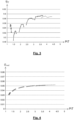
- THE figures 3 and 4 show functional characteristics of the efficiency ⁇ T and the permeability Q red of the turbine 4 for a given turbocharger position. Each curve represents a reduced turbine iso-speed N red .
- Q W.G. S eff x P 3 t R . T 3 1 ⁇ T 1 ⁇ ⁇ ⁇ ⁇ 1 1 ⁇ 1 ⁇ T ⁇ ⁇ 1 ⁇ 1 2
- Equation (23) is a function of the position of the discharge valve as well as the expansion of turbine 4:
- Q W.G. T 3 P 3 t S eff x . h 12 ⁇ T
- the system of equations (28) is a system of nonlinear equations with two unknowns. It admits a unique solution if and only if the functions g and h are strictly monotonic.
- FIG. 6 shows the different software modules that can be implemented in the engine computer 26 to calculate the set position of the turbocharger x.
- the module M1 makes it possible to determine the adapted power P adapt which is a function of the power P comp sent to the compressor 3, the pressure P 4 downstream of the turbine 4, and the temperature T 3 upstream of the turbine 4.
- the module M2 allows you to calculate the square root of the temperature T 3 .
- the module M3 makes it possible to determine the adapted flow rate Q adapt which is a function of the exhaust gas flow rate Q ech , the pressure P 4 downstream of the turbine 4, and the temperature T 3 upstream of the turbine 4.
- the M4 module determines the set position of the turbocharger Cons_pos_turb from the adapted power P adapt and the adapted flow rate Q adapt previously determined.
- the relationship between the turbocharger set position and the adapted power torque P adapt - adapted flow rate Q adapt is obtained from engine tests or from from functional data of the turbine 4 provided in particular by the supplier of turbocharger 2.
- the turbocharger 2 is controlled according to the previously determined setpoint position.
- THE figures 7 and 8 show curves with iso-expansion rate of turbine 4 (dotted curves) and iso-position of turbocharger 2 in an adapted power field P adapt -adapted flow rate Q adapt for a turbocharger 2 respectively with fixed geometry and variable geometry.
- turbocharger 2 is unique for a given P adapt / Q adapt couple, which is consistent with the calculations detailed in expressions (28) to (32).
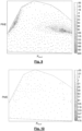
- THE figures 9 and 10 are graphical representations of the boost pressure error (PME) as a function of the speed-power operating point N word obtained respectively with a method according to the state of the art and a method according to the invention.
- PME boost pressure error
- boost pressure error varies from -50 to 200 mbar with the process according to the state of the art, and varies from -35 to 35 mbar with the process according to the invention.
- the boost pressure error is thus more reduced and centered with the method according to the invention compared to the method according to the state of the art which generates a greater heterogeneous error.
Landscapes
- Engineering & Computer Science (AREA)
- Chemical & Material Sciences (AREA)
- Combustion & Propulsion (AREA)
- Mechanical Engineering (AREA)
- General Engineering & Computer Science (AREA)
- Supercharger (AREA)
Description
- La présente invention porte sur un procédé de calcul d'une position de consigne d'un turbocompresseur de moteur thermique. L'invention trouve une application particulièrement avantageuse, mais non exclusive, dans le domaine des moteurs thermiques de véhicules automobiles.
- De façon connue en soi, un turbocompresseur comporte un compresseur et une turbine reliée mécaniquement au compresseur. Le compresseur comprime l'air d'admission afin d'optimiser le remplissage des chambres de combustion. A cet effet, le compresseur est placé sur le conduit d'admission de l'air, c'est-à-dire avant le moteur. L'écoulement des gaz d'échappement entraîne en rotation la turbine qui entraîne alors en rotation le compresseur par l'intermédiaire d'un arbre d'accouplement reliant les éléments entre eux.
- Un turbocompresseur comporte une turbine du type à géométrie fixe (TGF) ou à géométrie variable (TGV). Un turbocompresseur à géométrie fixe comporte une soupape de décharge permettant à une partie des gaz d'échappement de ne pas passer par la turbine. Un turbocompresseur à géométrie variable présente des ailettes permettant de faire varier la section de passage des gaz d'échappement. Une consigne de position du turbocompresseur (la position de la soupape de décharge pour le turbocompresseur à géométrie fixe ou la position des ailettes pour le turbocompresseur à géométrie variable) permet d'atteindre la consigne de pression de suralimentation.
- Ccette consigne de position est généralement élaborée à partir des équations de base régissant le fonctionnement de la turbine. Cette façon de procéder engendre implicitement un bouclage avec la position de la turbine courante. Cela implique plusieurs inconvénients, notamment le manque de précision, d'homogénéité, ainsi que des difficultés de calibration. En effet, la complexité de ce calcul et la présence de ce bouclage ne permettent pas d'atteindre ou d'améliorer la précision en ciblant judicieusement les paramètres mis en jeux tels que les champs turbine, le rendement turbine, ou la section efficace de passage des gaz dans le cas d'une soupape de décharge. Par conséquent, l'erreur commise par cette méthode est inhomogène en fonction des conditions d'utilisation de la turbine.
- On connait encore du document
DE102004051837A1 une méthode de contrôle d'un turbocompresseur. - L'invention vise à remédier efficacement à ces inconvénients en proposant un procédé de calcul d'une position de consigne d'un turbocompresseur de moteur thermique muni d'un compresseur et d'une turbine destinée à être entraînée par des gaz d'échappement, caractérisé en ce que le procédé comporte:
- une étape de détermination d'une puissance adaptée Padapt déterminée à partir de la formule suivante:

- une étape de détermination d'un débit adapté Qadapt déterminé à partir de la formule suivante:

- une étape de détermination de la position de consigne du turbocompresseur à partir de la puissance adaptée Padapt et du débit adapté Qadapt , et
- une étape de pilotage du turbocompresseur en fonction de la position de consigne précédemment déterminée.
- L'invention permet ainsi, en utilisant une pression de sortie de la turbine, de supprimer le bouclage avec la position courante du turbocompresseur qui est source d'erreur de calcul. En outre, grâce à l'invention, la nouvelle consigne de position de la turbine recherchée est obtenue simplement à partir d'un champ unique dépendant de deux variables d'entrée uniquement. Cette réduction de variables d'entrée facilite la calibration du procédé. L'invention est basée sur un principe générique adapté à un turbocompresseur à géométrie fixe (TGF) ou variable (TGV).
- Selon une mise en oeuvre, une relation entre la position de consigne du turbocompresseur et un couple puissance adaptée Padapt -débit adapté Qadapt est obtenue à partir d'essais moteur.
- Selon une mise en oeuvre, une relation entre la position de consigne du turbocompresseur et un couple puissance adaptée Padapt -débit adapté Qadapt est obtenue à partir de données fonctionnelles de la turbine du turbocompresseur.
- Selon une mise en oeuvre, le turbocompresseur comporte une turbine à géométrie variable.
- Selon une mise en oeuvre avec une turbine à géométrie variable, la position de consigne est la position de consigne des ailettes de la turbine.
- Selon une mise en oeuvre, le turbocompresseur comporte une turbine à géométrie fixe.
- Selon une mise en oeuvre avec une turbine à géométrie fixe, la position de consigne est la position de consigne d'une soupape de décharge du turbocompresseur.
- L'invention a également pour objet un calculateur moteur comportant une mémoire stockant des instructions logicielles pour la mise en oeuvre du procédé de calcul d'une position de consigne d'un turbocompresseur de moteur thermique tel que précédemment défini.
- L'invention a également pour objet un véhicule automobile caractérisé en ce qu'il comporte un calculateur moteur tel que précédemment défini.
- L'invention sera mieux comprise à la lecture de la description qui suit et à l'examen des figures qui l'accompagnent. Ces figures ne sont données qu'à titre illustratif mais nullement limitatif de l'invention.
- La
figure 1 est une représentation schématique d'une architecture de véhicule automobile avec laquelle est mis en oeuvre un procédé selon l'invention de calcul d'une position de consigne d'un turbocompresseur de moteur thermique; - La
figure 2 est un diagramme d'une loi de commande de suralimentation avec bouclage sur l'estimation de la pression en entrée de la turbine; - Les
figures 3 et 4 sont des représentations graphiques de caractéristiques fonctionnelles de rendement et de perméabilité de la turbine pour une position donnée du turbocompresseur; - La
figure 5 est une représentation graphique de la perméabilité de la turbine en fonction d'un taux de détente; - La
figure 6 est un diagramme de la loi de commande du calcul de la position du turbocompresseur selon l'invention; - Les
figures 7 et 8 montrent des courbes à iso-taux de détente de la turbine et iso-position du turbocompresseur dans un champ puissance adaptée/débit adapté pour un turbocompresseur respectivement à géométrie fixe et à géométrie variable; - Les
figures 9 et 10 sont des représentations graphiques de l'erreur de pression de suralimentation en fonction du point de fonctionnement régime-puissance obtenue respectivement avec un procédé selon l'état de la technique et un procédé selon l'invention. - La
figure 1 montre un exemple d'architecture de véhicule automobile 1 comportant un moteur thermique 5 suralimenté par un turbocompresseur 2 comprenant un compresseur 3 et une turbine 4. Le compresseur 3 permet de comprimer l'air d'admission de manière à optimiser le remplissage des cylindres du moteur 5. A cet effet, le compresseur 3 est disposé sur une conduite d'admission 8 en amont du moteur 5. L'écoulement des gaz d'échappement entraîne en rotation la turbine 4 disposée sur une conduite d'échappement 9, laquelle entraîne alors en rotation le compresseur 3 par l'intermédiaire d'un arbre d'accouplement. - Dans le cas d'un turbocompresseur 2 ayant une turbine 4 à géométrie fixe, une vanne de décharge 15 permet de gérer la quantité de gaz d'échappement circulant à travers la turbine 4 et la quantité de gaz passant par une conduite de décharge 16. Alternativement, le turbocompresseur 2 muni d'une turbine 4 à géométrie variable comporte des ailettes permettant de faire varier la section de passage des gaz d'échappement.
- De manière à maintenir la densité de l'air acquise en sortie du compresseur 3, on utilise un échangeur de chaleur 10 dit RAS (pour "Refroidisseur d'Air de Suralimentation") apte à refroidir l'air circulant dans la conduite d'admission 8. L'échangeur 10 est monté en aval du compresseur 3 et en amont d'un doseur d'air 18.
- Par ailleurs, un système 23 de recirculation des gaz d'échappement (dit "EGR" pour "Exhaust Gaz Recirculation" en anglais) comporte une conduite de redirection 27 des gaz d'échappement apte à rediriger une partie des gaz d'échappement issus d'un collecteur d'échappement 20 vers le répartiteur d'admission 28 du moteur 5 après passage dans un échangeur 14. Ainsi, une partie des gaz d'échappement du moteur 5 est rejetée vers l'extérieur du véhicule automobile à travers la conduite d'échappement 9 et une autre partie des gaz est recyclée. La quantité de gaz devant être remise en circulation est contrôlée par la vanne EGR 25 montée en amont du répartiteur d'admission 28.
- Un calculateur moteur 26 est apte à piloter les différents organes du véhicule, en particulier l'injection du moteur thermique 5, la turbine 4 du turbocompresseur 2, le doseur d'air 18, et la vanne EGR 25. Ce calculateur 26 comporte une mémoire stockant des instructions logicielles pour la mise en oeuvre du procédé selon l'invention de calcul d'une position de consigne du turbocompresseur 2.
- La
figure 2 montre un schéma de commande de la pression de suralimentation d'un moteur thermique 5. Il intègre deux boucles de régulation de type PID (Pour "Proportionnel, Intégral, Dérivé"). La première boucle B1 (interne) régule la position du turbocompresseur 2 à géométrie fixe ou variable. La deuxième boucle (externe) B2 régule la pression de suralimentation. Ce système de commande suppose la mesure de la pression de suralimentation P_sur_mes du moteur thermique 5 ainsi que la position du turbocompresseur Pos_turb (x). Cette dernière permet de mesurer la levée de la tige de l'actionneur pilotant soit la vanne de décharge 15 ou les ailettes du turbocompresseur 2 à géométrie variable. - Plus précisément, un comparateur Comp permet de calculer une erreur entre la consigne de pression de suralimentation Cons_P_sural et la pression de suralimentation mesurée P_sur_mes. Un bloc de régulation PID corrige cette erreur et le résultat est ajouté à la consigne de pression de suralimentation Cons_P_sural via le sommateur Som.
- Le système de suralimentation est non-linéaire. Cette non-linéarité est notamment intrinsèque au turbocompresseur 2. Afin de linéariser ce système vis-à-vis du régulateur, un modèle inverse de ce dernier est intégré dans la loi de commande.
- Le module P_Comp détermine ainsi à partir de la consigne de pression de suralimentation corrigée Cons_P_sural_corr la puissance de compresseur requise Cons_puiss_comp. Ensuite, cette dernière est traduite en consigne de perméabilité de la soupape de décharge via le modèle inverse de la turbine Mod_inv_turb. Enfin, cette perméabilité est convertie à son tour en consigne de position de turbocompresseur via le modèle Cons_pos_turb.
- Cette inversion nécessite de connaitre la pression en amont de la turbine Est_P_E_turb. Or pour la connaitre, il faut connaitre la position réelle du turbocompresseur Pos_turb, elle-même déterminée par la consigne de la position Cons_pos_turb. Il y a donc un bouclage, via un bloc de régulation Reg_pos, de type PID, au niveau de la consigne de position Cons_pos_turb du turbocompresseur 2.
- Afin de supprimer ce bouclage, l'invention modifie la structure de consigne de position Cons_pos_turb du turbocompresseur 2 et le modèle inverse de la puissance de la turbine Mod_inv_turb du module M.
- On détaille ci-après la nouvelle structure d'inversion de la puissance de la turbine et de calcul de la consigne de position du turbocompresseur 2.
- Les différentes variables utilisées dans les différents calculs sont définies dans le tableau ci-dessous :
Notation Définition Pturb Puissance récupérée par la turbine Pcomp Puissance envoyée au compresseur N Régime du turbocompresseur Nmot Régime moteur Nred Régime réduit turbine Qcomp Débit compresseur Qremp Débit moteur Qred Débit réduit turbine Qturb Débit turbine Qech Débit échappement QWG Débit de la vanne de décharge Qcarb Débit carburant R Constante des gaz parfait T3 Température amont turbine T 3t Température amont turbine (totale) P 4 Pression aval turbine P 3 Pression amont turbine P3t Pression amont turbine (totale) ηT Rendement turbine cp Capacité calorifique des gaz échappement πT Taux de détente turbine γ Coefficient adiabatique des gaz échappement Seff Section efficace de la vanne de décharge x Position du turbocompresseur - Dans la suite de la description, les hypothèses suivantes sont faites :
- la température d'échappement totale est considérée connue et est égale à la température d'échappement statique :

- la puissance du compresseur est connue. Cette dernière est obtenue via l'équation suivante :

- la turbine 4 se caractérise complètement par les données fonctionnelles suivantes :
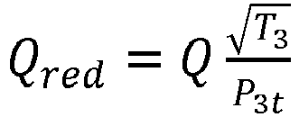
- la perméabilité :

- le rendement :


- Les
figures 3 et 4 montrent des caractéristiques fonctionnelles du rendement ηT et de la perméabilité Qred de la turbine 4 pour une position de turbocompresseur donnée. Chaque courbe représente un iso-régime réduit de turbine Nred. - Afin d'introduire la nouvelle approche de calcul de la consigne de position Cons_pos_turb du turbocompresseur 2, on exploite la donnée suivante : à une position de turbocompresseur 2 donnée (TGV ou TGF), et pour un iso-régime du turbocompresseur 2 donné, l'équilibrage des puissances du compresseur 3 et de la turbine 4 impose l'unicité du point d'équilibre entre le compresseur 3 et la turbine 4. Par conséquent, on ne retient qu'une seule valeur de rendement par iso-régime du turbocompresseur 2.
- Les caractéristiques fonctionnelles de la turbine (3) et (4) deviennent donc :
- la perméabilité :

- le rendement :

- Les propriétés des gaz sont constantes et considérées indépendantes de la température :


- On définit les variables suivantes :
- Puissance adaptée :

- Avec Pturb :

- En régime stabilisé (c'est-à-dire à vitesse de turbocompresseur 2 constante), comme Pturb = Pcomp , on a donc :

- Le débit adapté s'exprime de la façon suivante :


- Pour le calcul de la puissance adaptée Padapt, en remplaçant (8) dans (7) et en multipliant et en divisant par P 3t pour faire apparaître le taux de détente de la turbine 4 (πT = P 3t/P 4), on obtient :

- En réorganisant les différents termes de l'équation (12), on fait apparaitre également la perméabilité de la turbine


- Selon les équations (5) et (6), on en déduit finalement la relation :

- On constate donc que la puissance de la turbine adaptée Padapt dépend uniquement de la détente et de la position de la turbine 4.
- Pour le calcul du débit de la turbine adapté Qadapt, à partir des équations (10) et (11) et en multipliant et en divisant à nouveau par P3t pour faire apparaitre le taux de détente de la turbine (πT = P 3t/P 4) , on obtient :

- Afin d'expliciter le débit d'échappement Qech, on distingue deux cas. Dans le cas d'une turbine à géométrie variable (TGV), en remplaçant l'équation (11) dans (16), on fait apparaitre la perméabilité de la turbine


- Selon l'équation (5), on obtient finalement :

- On constate également que le débit de la turbine adapté Qadapt dépend uniquement de la détente et de la position de la turbine 4.
- Dans le cas d'une turbine 4 à géométrie fixe (TGF), à partir des équations (10), (11) et en multipliant et en divisant à nouveau par P3t pour faire apparaitre le taux de détente de la turbine (πT = P 3t/P 4) , on obtient :

- Selon l'équation de Barré Saint Venant, le débit de la vanne de décharge QWG s'écrit :

- D'où en multipliant par


- On constate donc que le terme de gauche de l'équation (23) est fonction de la position de la vanne de décharge ainsi que de la détente de la turbine 4 :

- Par ailleurs, selon les équations (18), (19) et (20), nous avons :

- En remplaçant (24) et (25) dans (21), on obtient :

- On constate alors que :

- Finalement on montre que, quelle que soit la technologie de turbocompresseur 2 (TGV ou TGF), on a :

- Le système d'équations (28) est un système d'équations non linéaires à deux inconnues. Il admet une solution unique si et seulement si les fonctions g et h sont strictement monotones.
- Pour une position du turbocompresseur donnée x 0, on peut montrer que la fonction Padapt = g(πT, x0 ) est strictement croissante :

- En effet, Qred (πT ,x 0) et

- On peut donc inverser la fonction g selon :

- On réinjecte ensuite cette expression dans la fonction g :

- De la même façon, on montre que pour une position du turbocompresseur donnée x0, la fonction Qadapt = h(πT ,x 0) qui s'apparente à la perméabilité de la turbine 4 est strictement croissante.
- La
figure 5 montre ainsi que la perméabilité de la turbine est une fonction croissante en fonction du taux de détente πT. - Finalement, les fonctions g et h étant inversibles, on peut exprimer la position du turbocompresseur x 0 en fonction de la puissance et débit adaptés :

- Donc connaissant la puissance adaptée Padapt et le débit adapté Qadapt, on peut en déduire la position du turbocompresseur Cons_pos_turb.
- La
figure 6 montre les différents modules logiciels pouvant être implémentés dans le calculateur moteur 26 pour effectuer le calcul de la position de consigne du turbocompresseur x. - Le module M1 permet de déterminer la puissance adaptée Padapt qui est fonction de la puissance Pcomp envoyée au compresseur 3, de la pression P4 en aval de la turbine 4, et de la température T3 en amont de la turbine 4. Le module M2 permet de calculer la racine carrée de la température T3.
- Le module M3 permet de déterminer le débit adapté Qadapt qui est fonction du débit de gaz d'échappement Qech, de la pression P4 en aval de la turbine 4, et de la température T3 en amont de la turbine 4.
- Le module M4 détermine la position de consigne du turbocompresseur Cons_pos_turb à partir de la puissance adaptée Padapt et du débit adapté Qadapt précédemment déterminés.
- La relation entre la position de consigne du turbocompresseur et le couple puissance adaptée Padapt-débit adapté Qadapt est obtenue à partir d'essais moteur ou à partir de données fonctionnelles de la turbine 4 fournies notamment par le fournisseur de turbocompresseur 2. Le turbocompresseur 2 est piloté en fonction de la position de consigne précédemment déterminée.
- On fournit ci-après des exemples de caractérisation de turbine 4 à géométrie fixe (TGF) et à géométrie variable (TGV) issus de données fournisseur.
- Les
figures 7 et 8 montrent des courbes à iso-taux de détente de la turbine 4 (courbes en pointillés) et iso-position du turbocompresseur 2 dans un champ puissance adaptée Padapt-débit adapté Qadapt pour un turbocompresseur 2 respectivement à géométrie fixe et à géométrie variable. - On observe que la position du turbocompresseur 2 est unique pour un couple Padapt / Qadapt donné, ce qui est cohérent avec les calculs détaillés dans les expressions (28) à (32).
- Les
figures 9 et 10 sont des représentations graphiques de l'erreur de pression de suralimentation (PME) en fonction du point de fonctionnement régime-puissance Nmot obtenue respectivement avec un procédé selon l'état de la technique et un procédé selon l'invention. - Il en ressort que l'erreur de pression de suralimentation varie de -50 à 200 mbar avec le procédé selon l'état de la technique, et varie de -35 à 35 mbar avec le procédé selon l'invention.
- L'erreur de pression de suralimentation est ainsi plus réduite et centrée avec le procédé selon l'invention comparé au procédé selon l'état de la technique qui engendre une erreur hétérogène plus importante.
Claims (9)
- Procédé de calcul d'une position de consigne (Cons_pos_turb) d'un turbocompresseur (2) de moteur thermique (5) muni d'un compresseur (3) et d'une turbine (4) destinée à être entraînée par des gaz d'échappement, caractérisé en ce que ledit procédé comporte:- une étape de détermination d'une puissance adaptée Padapt déterminée à partir de la formule suivante:
 - une étape de détermination d'un débit adapté Qadapt déterminé à partir de la formule suivante:
 - une étape de détermination de la position de consigne (Cons_pos_turb) du turbocompresseur (2) à partir de la puissance adaptée Padapt et du débit adapté Qadapt, et- une étape de pilotage du turbocompresseur (2) en fonction de la position de consigne (Cons_pos_turb) précédemment déterminée.
 - Procédé selon la revendication 1, caractérisé en ce qu'une relation entre la position de consigne (Cons_pos_turb) du turbocompresseur (2) et un couple puissance adaptée Padapt-débit adapté Qadapt est obtenue à partir d'essais moteur.
- Procédé selon la revendication 1, caractérisé en ce qu'une relation entre la position de consigne (Cons_pos_turb) du turbocompresseur (2) et un couple puissance adaptée P adapt-débit adapté Qadapt est obtenue à partir de données fonctionnelles de la turbine (4) du turbocompresseur (2).
- Procédé selon l'une quelconque des revendications 1 à 3, caractérisé en ce que le turbocompresseur (2) comporte une turbine (4) à géométrie variable.
- Procédé selon la revendication 4, caractérisé en ce que la position de consigne est la position de consigne des ailettes de la turbine (4).
- Procédé selon l'une quelconque des revendications 1 à 3, caractérisé en ce que le turbocompresseur (2) comporte une turbine (4) à géométrie fixe.
- Procédé selon la revendication 6, caractérisé en ce que la position de consigne est la position de consigne d'une soupape de décharge du turbocompresseur.
- Calculateur moteur (26) comportant une mémoire stockant des instructions logicielles pour la mise en oeuvre du procédé de calcul d'une position de consigne (Cons_pos_turb) d'un turbocompresseur (2) de moteur thermique (5) tel que défini selon l'une quelconque des revendications précédentes.
- Véhicule automobile caractérisé en ce qu'il comporte un calculateur moteur (26) tel que défini selon la revendication 8.
Applications Claiming Priority (2)
| Application Number | Priority Date | Filing Date | Title |
|---|---|---|---|
| FR1857767A FR3085430B1 (fr) | 2018-08-29 | 2018-08-29 | Procede de calcul d'une position de consigne d'un turbocompresseur de moteur thermique |
| PCT/FR2019/051706 WO2020043964A1 (fr) | 2018-08-29 | 2019-07-09 | Procede de calcul d'une position de consigne d'un turbocompresseur de moteur thermique |
Publications (2)
| Publication Number | Publication Date |
|---|---|
| EP3844377A1 EP3844377A1 (fr) | 2021-07-07 |
| EP3844377B1 true EP3844377B1 (fr) | 2024-03-20 |
Family
ID=63722650
Family Applications (1)
| Application Number | Title | Priority Date | Filing Date |
|---|---|---|---|
| EP19753147.8A Active EP3844377B1 (fr) | 2018-08-29 | 2019-07-09 | Procede de calcul d'une position de consigne d'un turbocompresseur de moteur thermique |
Country Status (4)
| Country | Link |
|---|---|
| EP (1) | EP3844377B1 (fr) |
| CN (1) | CN112639271A (fr) |
| FR (1) | FR3085430B1 (fr) |
| WO (1) | WO2020043964A1 (fr) |
Families Citing this family (2)
| Publication number | Priority date | Publication date | Assignee | Title |
|---|---|---|---|---|
| FR3115329B1 (fr) * | 2020-10-19 | 2024-04-12 | Psa Automobiles Sa | Procede de determination d’une consigne de position maximale de turbine de turbocompresseur |
| CN120351071B (zh) * | 2025-06-24 | 2025-08-29 | 凤城市东宁动力有限公司 | 涡轮增压器温度pid协同控制方法及参数优化系统 |
Family Cites Families (7)
| Publication number | Priority date | Publication date | Assignee | Title |
|---|---|---|---|---|
| DE102004051837B4 (de) * | 2004-10-25 | 2006-11-09 | Siemens Ag | Verfahren und Vorrichtungen zum Steuern und zum Diagnostizieren eines Abgasturboladers |
| FR2910055B1 (fr) * | 2006-12-15 | 2010-09-24 | Peugeot Citroen Automobiles Sa | Methode de determination d'une pression en entree d'une turbine de turbocompresseur equipant un moteur thermique |
| FR2921114B1 (fr) * | 2007-09-13 | 2018-01-12 | Peugeot Citroen Automobiles Sa | Methode de determination d'une pression en entree d'une turbine de turbocompresseur equipant un moteur thermique |
| US20140363278A1 (en) * | 2013-06-11 | 2014-12-11 | Deere & Company | Variable geometry turbocharger control system |
| DE102014217456B3 (de) * | 2014-09-02 | 2015-08-06 | Continental Automotive Gmbh | Verfahren zur Ermittlung eines Ansteuersignals für den Aktuator des Wastegates eines Abgasturboladers eines Kraftfahrzeugs |
| US9879593B2 (en) * | 2015-12-03 | 2018-01-30 | GM Global Technology Operations LLC | System and method for adaptively learning values and controlling a turbocharger of an engine based on the values |
| US10584630B2 (en) * | 2016-06-06 | 2020-03-10 | Fca Us Llc | Power-based turbocharger boost control techniques |
-
2018
- 2018-08-29 FR FR1857767A patent/FR3085430B1/fr not_active Expired - Fee Related
-
2019
- 2019-07-09 EP EP19753147.8A patent/EP3844377B1/fr active Active
- 2019-07-09 CN CN201980057103.2A patent/CN112639271A/zh active Pending
- 2019-07-09 WO PCT/FR2019/051706 patent/WO2020043964A1/fr not_active Ceased
Also Published As
| Publication number | Publication date |
|---|---|
| CN112639271A (zh) | 2021-04-09 |
| EP3844377A1 (fr) | 2021-07-07 |
| WO2020043964A1 (fr) | 2020-03-05 |
| FR3085430A1 (fr) | 2020-03-06 |
| FR3085430B1 (fr) | 2021-05-21 |
Similar Documents
| Publication | Publication Date | Title |
|---|---|---|
| US20130042609A1 (en) | Unit for estimating the rotational speed of a turbocharger and system and method for controlling an internal combustion engine with a turbocharger | |
| FR3065990A1 (fr) | Procede de reactualisation d’une dynamique d’adaptation d’une valeur de richesse a une consigne dans un moteur | |
| EP3844377B1 (fr) | Procede de calcul d'une position de consigne d'un turbocompresseur de moteur thermique | |
| EP2956651B1 (fr) | Procede de determination de la pression de gaz d'echappement en amont du turbocompresseur et du debit traversant sa turbine | |
| FR2915237A1 (fr) | Systeme et procede de commande d'un turbocompresseur de suralimentation pour moteur a combustion interne | |
| EP2061961B1 (fr) | Systeme de commande pour l'estimation du debit d'air frais entrant dans un moteur a combustion interne et procede associe | |
| EP2699778B1 (fr) | Procede de diagnostic de defaillance d'un moteur suralimente et moteur suralimente | |
| JP5664774B2 (ja) | 内燃機関の制御装置 | |
| FR2849112A1 (fr) | Procede de commande d'elements d'execution de fonctions elementaires de moteur a combustion interne | |
| FR3132546A1 (fr) | Procédé de contrôle du débit dans un conduit de recirculation partielle de gaz d’échappement à l’admission d’un moteur et dispositif associé | |
| WO2008084169A2 (fr) | Procede d'estimation de la pression des gaz d'echappement en amont d'une turbine de turbocompresseur | |
| FR2923538A3 (fr) | Systeme et procede d'estimation de la pression en amont d'une turbine de turbocompresseur et moteur thermique associ associe | |
| FR3119867A1 (fr) | Procede de compensation de dispersions et de derives d'un systeme de suralimentation muni d'un turbocompresseur a geometrie variable | |
| FR3085432A1 (fr) | Procede d'estimation d'une temperature d'un melange air-gaz d'echappement recircules d'un moteur thermique | |
| EP3067539B1 (fr) | Procédé de détermination de la vitesse de rotation du turbocompresseur d'un moteur à combustion interne de véhicule automobile | |
| EP2751416B1 (fr) | Système et procédé de commande d'un moteur a combustion interne d'un véhicule automobile avec des circuits de recirculation de gaz d'échappement haute et basse pression en fonctionnement transitoire | |
| FR3088370A1 (fr) | Procede de calcul d'une position de consigne d'un turbocompresseur de moteur thermique | |
| FR3115565A1 (fr) | Procédé et système de correction d’une mesure de débit d’air admis dans un moteur à combustion interne | |
| EP4015808B1 (fr) | Système et procédé de commande d'un moteur à combustion interne basée sur le rendement de remplissage | |
| FR3033641B1 (fr) | Procede de determination de la pression en amont de la turbine d'un turbocompresseur d'un moteur a combustion interne de vehicule automobile. | |
| EP4222363B1 (fr) | Procédé de détermination de la masse de gaz aspiré dans un cylindre avec prise en compte des conditions réelles d'utilisation | |
| FR3082887A1 (fr) | Procede de determination d’une consigne de puissance d’un compresseur de moteur a combustion interne | |
| FR3146496A1 (fr) | Procede de determination d'une pression de suralimentation naturelle pour un moteur thermique suralimente | |
| FR3126450A1 (fr) | Procédé et système de commande d’un actionneur d’un moteur à combustion interne. | |
| EP3147491A1 (fr) | Procédé de commande d'un moteur à combustion interne de véhicule automobile |
Legal Events
| Date | Code | Title | Description |
|---|---|---|---|
| STAA | Information on the status of an ep patent application or granted ep patent |
Free format text: STATUS: UNKNOWN |
|
| STAA | Information on the status of an ep patent application or granted ep patent |
Free format text: STATUS: THE INTERNATIONAL PUBLICATION HAS BEEN MADE |
|
| STAA | Information on the status of an ep patent application or granted ep patent |
Free format text: STATUS: REQUEST FOR EXAMINATION WAS MADE |
|
| PUAI | Public reference made under article 153(3) epc to a published international application that has entered the european phase |
Free format text: ORIGINAL CODE: 0009012 |
|
| 17P | Request for examination filed |
Effective date: 20210125 |
|
| AK | Designated contracting states |
Kind code of ref document: A1 Designated state(s): AL AT BE BG CH CY CZ DE DK EE ES FI FR GB GR HR HU IE IS IT LI LT LU LV MC MK MT NL NO PL PT RO RS SE SI SK SM TR |
|
| DAV | Request for validation of the european patent (deleted) | ||
| DAX | Request for extension of the european patent (deleted) | ||
| GRAP | Despatch of communication of intention to grant a patent |
Free format text: ORIGINAL CODE: EPIDOSNIGR1 |
|
| STAA | Information on the status of an ep patent application or granted ep patent |
Free format text: STATUS: GRANT OF PATENT IS INTENDED |
|
| INTG | Intention to grant announced |
Effective date: 20231110 |
|
| RAP3 | Party data changed (applicant data changed or rights of an application transferred) |
Owner name: STELLANTIS AUTO SAS |
|
| GRAS | Grant fee paid |
Free format text: ORIGINAL CODE: EPIDOSNIGR3 |
|
| GRAA | (expected) grant |
Free format text: ORIGINAL CODE: 0009210 |
|
| STAA | Information on the status of an ep patent application or granted ep patent |
Free format text: STATUS: THE PATENT HAS BEEN GRANTED |
|
| REG | Reference to a national code |
Ref country code: DE Ref legal event code: R084 Ref document number: 602019048622 Country of ref document: DE |
|
| AK | Designated contracting states |
Kind code of ref document: B1 Designated state(s): AL AT BE BG CH CY CZ DE DK EE ES FI FR GB GR HR HU IE IS IT LI LT LU LV MC MK MT NL NO PL PT RO RS SE SI SK SM TR |
|
| REG | Reference to a national code |
Ref country code: GB Ref legal event code: FG4D Free format text: NOT ENGLISH |
|
| REG | Reference to a national code |
Ref country code: CH Ref legal event code: EP |
|
| REG | Reference to a national code |
Ref country code: DE Ref legal event code: R096 Ref document number: 602019048622 Country of ref document: DE |
|
| REG | Reference to a national code |
Ref country code: IE Ref legal event code: FG4D Free format text: LANGUAGE OF EP DOCUMENT: FRENCH |
|
| REG | Reference to a national code |
Ref country code: GB Ref legal event code: 746 Effective date: 20240410 |
|
| PG25 | Lapsed in a contracting state [announced via postgrant information from national office to epo] |
Ref country code: LT Free format text: LAPSE BECAUSE OF FAILURE TO SUBMIT A TRANSLATION OF THE DESCRIPTION OR TO PAY THE FEE WITHIN THE PRESCRIBED TIME-LIMIT Effective date: 20240320 |
|
| REG | Reference to a national code |
Ref country code: LT Ref legal event code: MG9D |
|
| PG25 | Lapsed in a contracting state [announced via postgrant information from national office to epo] |
Ref country code: GR Free format text: LAPSE BECAUSE OF FAILURE TO SUBMIT A TRANSLATION OF THE DESCRIPTION OR TO PAY THE FEE WITHIN THE PRESCRIBED TIME-LIMIT Effective date: 20240621 |
|
| PG25 | Lapsed in a contracting state [announced via postgrant information from national office to epo] |
Ref country code: HR Free format text: LAPSE BECAUSE OF FAILURE TO SUBMIT A TRANSLATION OF THE DESCRIPTION OR TO PAY THE FEE WITHIN THE PRESCRIBED TIME-LIMIT Effective date: 20240320 Ref country code: RS Free format text: LAPSE BECAUSE OF FAILURE TO SUBMIT A TRANSLATION OF THE DESCRIPTION OR TO PAY THE FEE WITHIN THE PRESCRIBED TIME-LIMIT Effective date: 20240620 |
|
| REG | Reference to a national code |
Ref country code: NL Ref legal event code: MP Effective date: 20240320 |
|
| PG25 | Lapsed in a contracting state [announced via postgrant information from national office to epo] |
Ref country code: RS Free format text: LAPSE BECAUSE OF FAILURE TO SUBMIT A TRANSLATION OF THE DESCRIPTION OR TO PAY THE FEE WITHIN THE PRESCRIBED TIME-LIMIT Effective date: 20240620 Ref country code: NO Free format text: LAPSE BECAUSE OF FAILURE TO SUBMIT A TRANSLATION OF THE DESCRIPTION OR TO PAY THE FEE WITHIN THE PRESCRIBED TIME-LIMIT Effective date: 20240620 Ref country code: LT Free format text: LAPSE BECAUSE OF FAILURE TO SUBMIT A TRANSLATION OF THE DESCRIPTION OR TO PAY THE FEE WITHIN THE PRESCRIBED TIME-LIMIT Effective date: 20240320 Ref country code: HR Free format text: LAPSE BECAUSE OF FAILURE TO SUBMIT A TRANSLATION OF THE DESCRIPTION OR TO PAY THE FEE WITHIN THE PRESCRIBED TIME-LIMIT Effective date: 20240320 Ref country code: GR Free format text: LAPSE BECAUSE OF FAILURE TO SUBMIT A TRANSLATION OF THE DESCRIPTION OR TO PAY THE FEE WITHIN THE PRESCRIBED TIME-LIMIT Effective date: 20240621 Ref country code: FI Free format text: LAPSE BECAUSE OF FAILURE TO SUBMIT A TRANSLATION OF THE DESCRIPTION OR TO PAY THE FEE WITHIN THE PRESCRIBED TIME-LIMIT Effective date: 20240320 Ref country code: BG Free format text: LAPSE BECAUSE OF FAILURE TO SUBMIT A TRANSLATION OF THE DESCRIPTION OR TO PAY THE FEE WITHIN THE PRESCRIBED TIME-LIMIT Effective date: 20240320 |
|
| REG | Reference to a national code |
Ref country code: AT Ref legal event code: MK05 Ref document number: 1668012 Country of ref document: AT Kind code of ref document: T Effective date: 20240320 |
|
| PG25 | Lapsed in a contracting state [announced via postgrant information from national office to epo] |
Ref country code: SE Free format text: LAPSE BECAUSE OF FAILURE TO SUBMIT A TRANSLATION OF THE DESCRIPTION OR TO PAY THE FEE WITHIN THE PRESCRIBED TIME-LIMIT Effective date: 20240320 Ref country code: LV Free format text: LAPSE BECAUSE OF FAILURE TO SUBMIT A TRANSLATION OF THE DESCRIPTION OR TO PAY THE FEE WITHIN THE PRESCRIBED TIME-LIMIT Effective date: 20240320 |
|
| PG25 | Lapsed in a contracting state [announced via postgrant information from national office to epo] |
Ref country code: NL Free format text: LAPSE BECAUSE OF FAILURE TO SUBMIT A TRANSLATION OF THE DESCRIPTION OR TO PAY THE FEE WITHIN THE PRESCRIBED TIME-LIMIT Effective date: 20240320 |
|
| PG25 | Lapsed in a contracting state [announced via postgrant information from national office to epo] |
Ref country code: NL Free format text: LAPSE BECAUSE OF FAILURE TO SUBMIT A TRANSLATION OF THE DESCRIPTION OR TO PAY THE FEE WITHIN THE PRESCRIBED TIME-LIMIT Effective date: 20240320 |
|
| PG25 | Lapsed in a contracting state [announced via postgrant information from national office to epo] |
Ref country code: IS Free format text: LAPSE BECAUSE OF FAILURE TO SUBMIT A TRANSLATION OF THE DESCRIPTION OR TO PAY THE FEE WITHIN THE PRESCRIBED TIME-LIMIT Effective date: 20240720 |
|
| PG25 | Lapsed in a contracting state [announced via postgrant information from national office to epo] |
Ref country code: PT Free format text: LAPSE BECAUSE OF FAILURE TO SUBMIT A TRANSLATION OF THE DESCRIPTION OR TO PAY THE FEE WITHIN THE PRESCRIBED TIME-LIMIT Effective date: 20240722 Ref country code: SM Free format text: LAPSE BECAUSE OF FAILURE TO SUBMIT A TRANSLATION OF THE DESCRIPTION OR TO PAY THE FEE WITHIN THE PRESCRIBED TIME-LIMIT Effective date: 20240320 |
|
| PG25 | Lapsed in a contracting state [announced via postgrant information from national office to epo] |
Ref country code: ES Free format text: LAPSE BECAUSE OF FAILURE TO SUBMIT A TRANSLATION OF THE DESCRIPTION OR TO PAY THE FEE WITHIN THE PRESCRIBED TIME-LIMIT Effective date: 20240320 |
|
| PG25 | Lapsed in a contracting state [announced via postgrant information from national office to epo] |
Ref country code: CZ Free format text: LAPSE BECAUSE OF FAILURE TO SUBMIT A TRANSLATION OF THE DESCRIPTION OR TO PAY THE FEE WITHIN THE PRESCRIBED TIME-LIMIT Effective date: 20240320 Ref country code: EE Free format text: LAPSE BECAUSE OF FAILURE TO SUBMIT A TRANSLATION OF THE DESCRIPTION OR TO PAY THE FEE WITHIN THE PRESCRIBED TIME-LIMIT Effective date: 20240320 |
|
| PG25 | Lapsed in a contracting state [announced via postgrant information from national office to epo] |
Ref country code: AT Free format text: LAPSE BECAUSE OF FAILURE TO SUBMIT A TRANSLATION OF THE DESCRIPTION OR TO PAY THE FEE WITHIN THE PRESCRIBED TIME-LIMIT Effective date: 20240320 |
|
| PG25 | Lapsed in a contracting state [announced via postgrant information from national office to epo] |
Ref country code: PL Free format text: LAPSE BECAUSE OF FAILURE TO SUBMIT A TRANSLATION OF THE DESCRIPTION OR TO PAY THE FEE WITHIN THE PRESCRIBED TIME-LIMIT Effective date: 20240320 |
|
| PG25 | Lapsed in a contracting state [announced via postgrant information from national office to epo] |
Ref country code: SK Free format text: LAPSE BECAUSE OF FAILURE TO SUBMIT A TRANSLATION OF THE DESCRIPTION OR TO PAY THE FEE WITHIN THE PRESCRIBED TIME-LIMIT Effective date: 20240320 |
|
| PG25 | Lapsed in a contracting state [announced via postgrant information from national office to epo] |
Ref country code: SM Free format text: LAPSE BECAUSE OF FAILURE TO SUBMIT A TRANSLATION OF THE DESCRIPTION OR TO PAY THE FEE WITHIN THE PRESCRIBED TIME-LIMIT Effective date: 20240320 Ref country code: SK Free format text: LAPSE BECAUSE OF FAILURE TO SUBMIT A TRANSLATION OF THE DESCRIPTION OR TO PAY THE FEE WITHIN THE PRESCRIBED TIME-LIMIT Effective date: 20240320 Ref country code: RO Free format text: LAPSE BECAUSE OF FAILURE TO SUBMIT A TRANSLATION OF THE DESCRIPTION OR TO PAY THE FEE WITHIN THE PRESCRIBED TIME-LIMIT Effective date: 20240320 Ref country code: PT Free format text: LAPSE BECAUSE OF FAILURE TO SUBMIT A TRANSLATION OF THE DESCRIPTION OR TO PAY THE FEE WITHIN THE PRESCRIBED TIME-LIMIT Effective date: 20240722 Ref country code: PL Free format text: LAPSE BECAUSE OF FAILURE TO SUBMIT A TRANSLATION OF THE DESCRIPTION OR TO PAY THE FEE WITHIN THE PRESCRIBED TIME-LIMIT Effective date: 20240320 Ref country code: IS Free format text: LAPSE BECAUSE OF FAILURE TO SUBMIT A TRANSLATION OF THE DESCRIPTION OR TO PAY THE FEE WITHIN THE PRESCRIBED TIME-LIMIT Effective date: 20240720 Ref country code: ES Free format text: LAPSE BECAUSE OF FAILURE TO SUBMIT A TRANSLATION OF THE DESCRIPTION OR TO PAY THE FEE WITHIN THE PRESCRIBED TIME-LIMIT Effective date: 20240320 Ref country code: EE Free format text: LAPSE BECAUSE OF FAILURE TO SUBMIT A TRANSLATION OF THE DESCRIPTION OR TO PAY THE FEE WITHIN THE PRESCRIBED TIME-LIMIT Effective date: 20240320 Ref country code: CZ Free format text: LAPSE BECAUSE OF FAILURE TO SUBMIT A TRANSLATION OF THE DESCRIPTION OR TO PAY THE FEE WITHIN THE PRESCRIBED TIME-LIMIT Effective date: 20240320 Ref country code: AT Free format text: LAPSE BECAUSE OF FAILURE TO SUBMIT A TRANSLATION OF THE DESCRIPTION OR TO PAY THE FEE WITHIN THE PRESCRIBED TIME-LIMIT Effective date: 20240320 |
|
| PG25 | Lapsed in a contracting state [announced via postgrant information from national office to epo] |
Ref country code: IT Free format text: LAPSE BECAUSE OF FAILURE TO SUBMIT A TRANSLATION OF THE DESCRIPTION OR TO PAY THE FEE WITHIN THE PRESCRIBED TIME-LIMIT Effective date: 20240320 |
|
| REG | Reference to a national code |
Ref country code: DE Ref legal event code: R097 Ref document number: 602019048622 Country of ref document: DE |
|
| PG25 | Lapsed in a contracting state [announced via postgrant information from national office to epo] |
Ref country code: IT Free format text: LAPSE BECAUSE OF FAILURE TO SUBMIT A TRANSLATION OF THE DESCRIPTION OR TO PAY THE FEE WITHIN THE PRESCRIBED TIME-LIMIT Effective date: 20240320 |
|
| PG25 | Lapsed in a contracting state [announced via postgrant information from national office to epo] |
Ref country code: DK Free format text: LAPSE BECAUSE OF FAILURE TO SUBMIT A TRANSLATION OF THE DESCRIPTION OR TO PAY THE FEE WITHIN THE PRESCRIBED TIME-LIMIT Effective date: 20240320 |
|
| PLBE | No opposition filed within time limit |
Free format text: ORIGINAL CODE: 0009261 |
|
| STAA | Information on the status of an ep patent application or granted ep patent |
Free format text: STATUS: NO OPPOSITION FILED WITHIN TIME LIMIT |
|
| PG25 | Lapsed in a contracting state [announced via postgrant information from national office to epo] |
Ref country code: DK Free format text: LAPSE BECAUSE OF FAILURE TO SUBMIT A TRANSLATION OF THE DESCRIPTION OR TO PAY THE FEE WITHIN THE PRESCRIBED TIME-LIMIT Effective date: 20240320 |
|
| PG25 | Lapsed in a contracting state [announced via postgrant information from national office to epo] |
Ref country code: MC Free format text: LAPSE BECAUSE OF FAILURE TO SUBMIT A TRANSLATION OF THE DESCRIPTION OR TO PAY THE FEE WITHIN THE PRESCRIBED TIME-LIMIT Effective date: 20240320 |
|
| 26N | No opposition filed |
Effective date: 20241223 |
|
| REG | Reference to a national code |
Ref country code: CH Ref legal event code: PL |
|
| PG25 | Lapsed in a contracting state [announced via postgrant information from national office to epo] |
Ref country code: LU Free format text: LAPSE BECAUSE OF NON-PAYMENT OF DUE FEES Effective date: 20240709 |
|
| PG25 | Lapsed in a contracting state [announced via postgrant information from national office to epo] |
Ref country code: LU Free format text: LAPSE BECAUSE OF NON-PAYMENT OF DUE FEES Effective date: 20240709 |
|
| PG25 | Lapsed in a contracting state [announced via postgrant information from national office to epo] |
Ref country code: BE Free format text: LAPSE BECAUSE OF NON-PAYMENT OF DUE FEES Effective date: 20240731 Ref country code: CH Free format text: LAPSE BECAUSE OF NON-PAYMENT OF DUE FEES Effective date: 20240731 Ref country code: SI Free format text: LAPSE BECAUSE OF FAILURE TO SUBMIT A TRANSLATION OF THE DESCRIPTION OR TO PAY THE FEE WITHIN THE PRESCRIBED TIME-LIMIT Effective date: 20240320 |
|
| REG | Reference to a national code |
Ref country code: BE Ref legal event code: MM Effective date: 20240731 |
|
| PGFP | Annual fee paid to national office [announced via postgrant information from national office to epo] |
Ref country code: GB Payment date: 20250619 Year of fee payment: 7 |
|
| PGFP | Annual fee paid to national office [announced via postgrant information from national office to epo] |
Ref country code: FR Payment date: 20250620 Year of fee payment: 7 |
|
| PG25 | Lapsed in a contracting state [announced via postgrant information from national office to epo] |
Ref country code: IE Free format text: LAPSE BECAUSE OF NON-PAYMENT OF DUE FEES Effective date: 20240709 |
|
| PGFP | Annual fee paid to national office [announced via postgrant information from national office to epo] |
Ref country code: DE Payment date: 20250620 Year of fee payment: 7 |
|
| PG25 | Lapsed in a contracting state [announced via postgrant information from national office to epo] |
Ref country code: CY Free format text: LAPSE BECAUSE OF FAILURE TO SUBMIT A TRANSLATION OF THE DESCRIPTION OR TO PAY THE FEE WITHIN THE PRESCRIBED TIME-LIMIT; INVALID AB INITIO Effective date: 20190709 |
|
| PG25 | Lapsed in a contracting state [announced via postgrant information from national office to epo] |
Ref country code: HU Free format text: LAPSE BECAUSE OF FAILURE TO SUBMIT A TRANSLATION OF THE DESCRIPTION OR TO PAY THE FEE WITHIN THE PRESCRIBED TIME-LIMIT; INVALID AB INITIO Effective date: 20190709 |