EP3843872B1 - Filteranordnung mit authentifizierender filterelementkopplung - Google Patents
Filteranordnung mit authentifizierender filterelementkopplung Download PDFInfo
- Publication number
- EP3843872B1 EP3843872B1 EP19874876.6A EP19874876A EP3843872B1 EP 3843872 B1 EP3843872 B1 EP 3843872B1 EP 19874876 A EP19874876 A EP 19874876A EP 3843872 B1 EP3843872 B1 EP 3843872B1
- Authority
- EP
- European Patent Office
- Prior art keywords
- filter element
- filter
- authenticating
- filter assembly
- bushing
- Prior art date
- Legal status (The legal status is an assumption and is not a legal conclusion. Google has not performed a legal analysis and makes no representation as to the accuracy of the status listed.)
- Active
Links
Images

Classifications
-
- B—PERFORMING OPERATIONS; TRANSPORTING
- B01—PHYSICAL OR CHEMICAL PROCESSES OR APPARATUS IN GENERAL
- B01D—SEPARATION
- B01D29/00—Filters with filtering elements stationary during filtration, e.g. pressure or suction filters, not covered by groups B01D24/00 - B01D27/00; Filtering elements therefor
- B01D29/96—Filters with filtering elements stationary during filtration, e.g. pressure or suction filters, not covered by groups B01D24/00 - B01D27/00; Filtering elements therefor in which the filtering elements are moved between filtering operations; Particular measures for removing or replacing the filtering elements; Transport systems for filters
-
- B—PERFORMING OPERATIONS; TRANSPORTING
- B01—PHYSICAL OR CHEMICAL PROCESSES OR APPARATUS IN GENERAL
- B01D—SEPARATION
- B01D35/00—Filtering devices having features not specifically covered by groups B01D24/00 - B01D33/00, or for applications not specifically covered by groups B01D24/00 - B01D33/00; Auxiliary devices for filtration; Filter housing constructions
- B01D35/14—Safety devices specially adapted for filtration; Devices for indicating clogging
- B01D35/147—Bypass or safety valves
-
- B—PERFORMING OPERATIONS; TRANSPORTING
- B01—PHYSICAL OR CHEMICAL PROCESSES OR APPARATUS IN GENERAL
- B01D—SEPARATION
- B01D29/00—Filters with filtering elements stationary during filtration, e.g. pressure or suction filters, not covered by groups B01D24/00 - B01D27/00; Filtering elements therefor
- B01D29/11—Filters with filtering elements stationary during filtration, e.g. pressure or suction filters, not covered by groups B01D24/00 - B01D27/00; Filtering elements therefor with bag, cage, hose, tube, sleeve or like filtering elements
- B01D29/13—Supported filter elements
- B01D29/15—Supported filter elements arranged for inward flow filtration
- B01D29/21—Supported filter elements arranged for inward flow filtration with corrugated, folded or wound sheets
-
- B—PERFORMING OPERATIONS; TRANSPORTING
- B01—PHYSICAL OR CHEMICAL PROCESSES OR APPARATUS IN GENERAL
- B01D—SEPARATION
- B01D29/00—Filters with filtering elements stationary during filtration, e.g. pressure or suction filters, not covered by groups B01D24/00 - B01D27/00; Filtering elements therefor
- B01D29/11—Filters with filtering elements stationary during filtration, e.g. pressure or suction filters, not covered by groups B01D24/00 - B01D27/00; Filtering elements therefor with bag, cage, hose, tube, sleeve or like filtering elements
- B01D29/13—Supported filter elements
- B01D29/23—Supported filter elements arranged for outward flow filtration
- B01D29/232—Supported filter elements arranged for outward flow filtration with corrugated, folded or wound sheets
-
- B—PERFORMING OPERATIONS; TRANSPORTING
- B01—PHYSICAL OR CHEMICAL PROCESSES OR APPARATUS IN GENERAL
- B01D—SEPARATION
- B01D35/00—Filtering devices having features not specifically covered by groups B01D24/00 - B01D33/00, or for applications not specifically covered by groups B01D24/00 - B01D33/00; Auxiliary devices for filtration; Filter housing constructions
- B01D35/30—Filter housing constructions
- B01D35/306—Filter mounting adapter
-
- B—PERFORMING OPERATIONS; TRANSPORTING
- B01—PHYSICAL OR CHEMICAL PROCESSES OR APPARATUS IN GENERAL
- B01D—SEPARATION
- B01D2201/00—Details relating to filtering apparatus
- B01D2201/04—Supports for the filtering elements
- B01D2201/0415—Details of supporting structures
-
- B—PERFORMING OPERATIONS; TRANSPORTING
- B01—PHYSICAL OR CHEMICAL PROCESSES OR APPARATUS IN GENERAL
- B01D—SEPARATION
- B01D2201/00—Details relating to filtering apparatus
- B01D2201/29—Filter cartridge constructions
- B01D2201/291—End caps
-
- B—PERFORMING OPERATIONS; TRANSPORTING
- B01—PHYSICAL OR CHEMICAL PROCESSES OR APPARATUS IN GENERAL
- B01D—SEPARATION
- B01D2201/00—Details relating to filtering apparatus
- B01D2201/30—Filter housing constructions
- B01D2201/301—Details of removable closures, lids, caps, filter heads
- B01D2201/305—Snap, latch or clip connecting means
-
- B—PERFORMING OPERATIONS; TRANSPORTING
- B01—PHYSICAL OR CHEMICAL PROCESSES OR APPARATUS IN GENERAL
- B01D—SEPARATION
- B01D2201/00—Details relating to filtering apparatus
- B01D2201/40—Special measures for connecting different parts of the filter
- B01D2201/4007—Use of cam or ramp systems
-
- B—PERFORMING OPERATIONS; TRANSPORTING
- B01—PHYSICAL OR CHEMICAL PROCESSES OR APPARATUS IN GENERAL
- B01D—SEPARATION
- B01D2201/00—Details relating to filtering apparatus
- B01D2201/40—Special measures for connecting different parts of the filter
- B01D2201/4046—Means for avoiding false mounting of different parts
- B01D2201/4053—Means for avoiding false mounting of different parts using keys
-
- B—PERFORMING OPERATIONS; TRANSPORTING
- B01—PHYSICAL OR CHEMICAL PROCESSES OR APPARATUS IN GENERAL
- B01D—SEPARATION
- B01D2201/00—Details relating to filtering apparatus
- B01D2201/40—Special measures for connecting different parts of the filter
- B01D2201/4076—Anti-rotational means
-
- B—PERFORMING OPERATIONS; TRANSPORTING
- B01—PHYSICAL OR CHEMICAL PROCESSES OR APPARATUS IN GENERAL
- B01D—SEPARATION
- B01D2201/00—Details relating to filtering apparatus
- B01D2201/52—Filter identification means
Definitions
- the present invention relates to filter assemblies according to the preambles of claims 1 and 7.
- Filtration systems are traditionally considered a fluid treatment and can also be considered as a part of contamination management.
- Contamination management is defined herein as relating to the analysis and optimization of processes with regard to the cleanliness of components, systems and the purity of the fluids used.
- contamination management is defined herein as relating to the analysis and optimization of processes with regard to the cleanliness of components, systems and the purity of the fluids used.
- smaller, lighter, and more powerful components are currently being used compared to only a decade ago.
- the use of these components also means that the demand of system cleanliness is now much higher, as has been shown by various studies. As much as 90% of all hydraulic system outages are due to increased contamination. This failure rate applies to more than classic hydraulics industry.
- Contamination management such as through the design and implementation of appropriate filter assemblies, is a key issue in the design and maintenance of hydraulic or fluid power systems used in a general sense for all industries.
- filtration systems include i) disposable units in which the filtration media and housing are integrated into a single use unit, often called “spin-ons" due to a commonly implemented threaded attachment technique; ii) filter assemblies having replaceable units in which the filtration media is formed in a filter element (AKA a filter cartridge) that can be removed from a unit housing forming a filter assembly; and iii) filtration units with cleanable media, which are cleaned by a process such as back-flushing.
- AKA filter cartridge
- a filter element also called a filter cartridge, within the meaning of this application, is a unit including filter media that is configured to be received in a filter assembly housing and is sometimes referenced as a drop in element.
- the filter assembly is one, or more, filter housings and associated filter elements together with other components of the unit such as a control, test points, particle counters, bypass valves, etc.
- the maintenance of a filter assembly having replaceable filter elements obviously requires the periodic replacement of the filter elements.
- One difficulty is that the replacement filter element must be suitable for the application in which it is being placed.
- the system can easily breakdown if a replaceable filter element is replaced with a filter element not rated for the particular application.
- WO 2018/162835 A1 discloses a filter assembly according to the preamble of claim 1, comprising: a filter element housing; an authenticating filter element coupling; and a replaceable drop-in twist locking filter element, wherein the housing includes a keyed bushing coupled thereto that provides an authenticating mechanism for a replaceable filter element suited for the specific housing wherein the keyed bushing forms one half of the authenticating coupling for the filter assembly.
- Additional filter assemblies are disclosed in WO 2013/106185 A1 , RU 56978 U1 , US 2006/0219621 A1 , US 2013/0228504 A1 , DE 10 2012 000 876 B3 , US 10 406 457 B2 , EP 1 731 210 A1 and DE 20 2006 011 990 U1 .
- a filter assembly comprising:
- a filter assembly comprising:
- a filter assembly includes an authenticating filter element coupling, formed of the combination of a keyed bushing and locking guide, and replaceable drop-in twist locking filter element therefor.
- the keyed bushing is coupled a housing of the filter assembly and provides an authenticating mechanism for a replaceable filter element suited for the specific housing wherein the keyed bushing forms one half of the authenticating filter element coupling for the filter assembly.
- the locking guide is coupled to an endcap of a filter element and the locking guide has a sleeve with slots in an end thereof that match keys of the associated keyed bushing on a filter housing. The locking guide forms one half of the authenticating coupling for the filter assembly.
- One aspect of the invention provides a filter assembly including a filter element housing an authenticating filter element coupling; and a replaceable drop-in twist locking filter element.
- the housing includes a keyed bushing coupled thereto that provides an authenticating mechanism for a replaceable filter element suited for the specific housing wherein the keyed bushing forms one half of the authenticating filter element coupling for the filter assembly.
- the filter assembly may provide wherein the keyed bushing includes a set of uniquely arranged keys on the radial periphery of the bushing.
- the filter assembly may provide wherein the keyed bushing includes a flange configured to rest on the housing and a sealing surface above the specific keys.
- the filter assembly may provide wherein the filter element includes an endcap with a sealing O-ring wherein the sealing surface is to be engaged with a sealing O-ring of the end cap of the filter element.
- the filter assembly may provide wherein the authenticating filter element coupling for the filter assembly includes a locking guide having a sleeve with slots in an end thereof that match the keys of the associated keyed bushing.
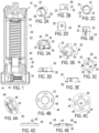
- This invention is directed to a cost effective, efficient, filter assembly 10 shown in Fig. 1 with a filter element housing 12 having an inlet/outlet 14, outlet/inlet 16 and bypass valve 18.
- Component 14 is an inlet and 16 an outlet when designed for outside-in flow and vice versa for inside-out flow.
- the bypass valve 18 is orientated to allow for bypass from the inlet (14 or 16) to the outlet (16 or 14) during blinding or clogging of the filter element, and obviously as shown will operate in only one direction. The configuration of the bypass valve 18 from that shown would change with a change in operational flow direction of the assembly 10.
- the invention is directed to a filter assembly 10 with an authenticating filter element coupling, formed of the combination of a keyed bushing 20 and locking guide 30, and replaceable drop-in twist locking filter element 50 therefor.
- the housing 12 includes a keyed bushing 20 coupled thereto that provides an authenticating mechanism for a replaceable filter element suited for the specific housing 12.
- the bushing 20 is press fit or threaded onto the housing 12.
- the keyed bushing 20 forms one half of the authenticating coupling for the filter assembly 10.
- the keyed bushing 20 is shown individually in Figs. 2A-E and includes a set of uniquely arranged keys 22 on the periphery of the bushing that are associated with, or in other words that define, a specific filter element rating/configuration for the assembly 10.
- the specific radial positioning of three keys 22 are believed to be sufficient to yield an extremely large number of unique key arrangements. Given that the specific keys 22 may have varied widths the possible unique position and size arrangements of three keys is effectively limitless.
- the keys 22 are orientated parallel to each other as opposed to radially extending so as to improve molding and allow simple two-piece mold construction.
- the keyed bushing includes a flange 24 to rest on the housing 12 and a sealing surface 26 above the specific keys 22.
- the sealing surface 26 is to be engaged with a sealing O-ring of the end cap 40 of the filter element 50.
- the inner diameter of the bushing 20 includes a notch 27 that assures the proper sealing occurs on the sealing surface 26 rather than on the inside surface.
- the authenticating coupling for the filter assembly 10 includes a locking guide 30 shown in Figs. 4A-D .
- the locking guide 30 forms one half of the authenticating coupling for the filter assembly 10 and includes a sleeve 32 with slots 34 in an end thereof that match the keys 22 of the associated keyed bushing 20.
- the sleeve 32 includes a detent member 36 or simply a detent 36 in the form of a ramp and perimeter stop that will engage with and secure one key 22 upon insertion and rotation of the filter element 50 and guide 30 relative to the keyed bushing 20.
- the leading key 22 will engage the ramp of the detent 36 and create a tight function lock with the stop of the detent 36 preventing further rotation.
- the locking guide 30 includes interconnect tab structures 38 for coupling a specific locking guide 30 to a given end cap 40 of a filter element 50.
- the locking guide 30 together with the keyed bushing 20 form an authenticating coupling and are unique to a given filter assembly rating or classification. Thus, only a filter element 50 with a matching locking guide 30 can be used with a given assembly 10 having the bushing 20.
- the locking guide 30 is secured to an endcap 40 of a filter element 50.
- the guide 30 may effectively be epoxied onto the endcap 40 and be integral therewith after coupling.
- the endcap 40 is shown in Figs. 4A-E and includes a sleeve 42 with radial sealing O-ring 44.
- the sleeve 42 of the endcap 40 receives the sealing face 26 of the keyed bushing 20 and the O-ring 44 seals against the sealing face 26.
- the slots 46 receive tabs 38 that engage detents 48 to secure the locking guide to the end cap 40.
- the construction and operation of slots 46 detents 48 and associated tab structure 38 is well known in the art and can take many forms for interconnecting these components.
- the filter element 50 includes filter media 52 extending between the endcap 40 and an upper endcap 54.
- the filter media 52 can be pleated media or composite media structures or any desired configuration.
- a unique keyed bushing 20 is developed and coupled to the assembly 10.
- the unique keyed bushing 20 matches with an associated locking guide 30 that is coupled to replaceable filter elements 50 having the designated rating for the assembly 10.
- Fig. 7 is a perspective view of a modified keyed bushing 120 of a modified authenticating filter element coupling of a filter assembly 10 of the present invention.
- the sealing face 126 is a radial flange 126 rather than a circumferential face, but still provides unique radial keys 122 (four in this embodiment).
- Fig. 8 is a perspective view of a modified integrated endcap and locking guide 140 of the modified authenticating filter element coupling of Fig. 7 .
- the sealing O-ring 144 is radially outside of the slots 134 that are sized to receive and match the keys 122.
- a detent 136 receives the keys 122 when twisted into position after insertion.
- the portion of the endcap and integrated locking guide 140 radially within the O-ring 144 could easily be formed by a grommet that is popped into a more generic outer portion.
- the position of the keyed bushing 20 on the housing 12 and the locking guide 30 may be reversed with the bushing 20 on the endcap 40 and the locking guide 30 on the housing 12.
- Fig. 9 illustrates a modified integrated endcap and key-shaped bushing 240 of a modified authenticating filter element coupling of the present invention.
- the endcap and key-shaped bushing 240 forms an endcap for a filter element 50 and includes an inner sleeve 242 and an outer sealing O-ring 244 sealing against a sealing face of a sleeve of a locking guide (not shown).
- the outer perimeter 246 is formed of a unique profile (here a rounded square) that matches with a unique profile of the locking guide (not shown) to form the authenticating coupling. Without the complementary shaped components, the O-ring seal 244 will not forma seal even if the bushing 240 were to fit.
- the embodiment of Fig. 9 is not a twist to lock arrangement, but is merely linearly advanced into position. The embodiment still provides the authentication desired.
Landscapes
- Chemical & Material Sciences (AREA)
- Chemical Kinetics & Catalysis (AREA)
- Filtration Of Liquid (AREA)
- Lubrication Details And Ventilation Of Internal Combustion Engines (AREA)
Claims (11)
- Filteranordnung (10) umfassend:- ein Filterelementgehäuse (12);- eine authentifizierende Filterelementkupplung (20, 30); und- ein austauschbares Drop-in-Drehverschluss-Filterelement (50),wobei das Gehäuse (12) eine damit gekoppelte Passfederbuchse (20) einschließt, die einen Authentifizierungsmechanismus für das austauschbare Filterelement (50) bereitstellt, das für das spezifische Gehäuse (12) geeignet ist, wobei die Passfederbuchse (20) eine Hälfte der authentifizierenden Filterelementkupplung (20, 30) für die Filteranordnung (10) bildet,dadurch gekennzeichnetdass die Passfederbuchse (20) einen Satz einzigartig angeordneter Passfedern (22) am radialen Umfang der Buchse (20) einschließt; unddass die Passfederbuchse (20) einen Flansch (24), der so konfiguriert ist, dass er auf dem Gehäuse (12) aufliegt, und eine Dichtungsfläche (26) oberhalb der Passfedern (22) einschließt.
- Filteranordnung nach Anspruch 1, wobei das Filterelement eine Endkappe (40) mit einem Dichtungs-O-Ring (44) einschließt, wobei die Dichtungsfläche (26) mit dem Dichtungs-O-Ring (44) der Endkappe (40) des Filterelements (50) in Eingriff zu bringen ist.
- Filteranordnung nach Anspruch 1, wobei die authentifizierende Filterelementkupplung (20, 30) für die Filteranordnung (10) eine Verriegelungsführung (30) einschließt, die eine Hülse (32) mit Schlitzen (34) an einem Ende davon aufweist, die mit den Passfedern (22) der zugeordneten Passfederbuchse (20) übereinstimmen.
- Filteranordnung nach Anspruch 3, wobei die Hülse (32) eine Raste (36) einschließt, die beim Einsetzen und Drehen des Filterelements (50) relativ zur Passfederbuchse (20) mit einer Passfeder (22) in Eingriff geht und diese sichert.
- Filteranordnung nach Anspruch 3, wobei die Verriegelungsführung Verbindungslaschenstrukturen (38) zum Koppeln einer spezifischen Verriegelungsführung (30) mit der gegebenen Endkappe (40) des Filterelements (50) einschließt.
- Filteranordnung nach Anspruch 3, wobei das austauschbare Drop-in-Drehverschluss-Filterelement (50) ein Filtermedium (52) einschließt, das sich zwischen einer unteren Endkappe (40) mit dem Dichtungs-O-Ring (44) und einer oberen Endkappe (54) erstreckt.
- Filteranordnung (10) umfassend:- ein Filterelementgehäuse (12);- eine authentifizierende Filterelementkupplung (20, 30); und- ein austauschbares Filterelement (50), das eine obere und untere Endkappe (54; 40) und ein Filtermedium (52) einschließt, das sich von der oberen Endkappe (54) zur unteren Endkappe (40) erstreckt, wobei die untere Endkappe (40) einen Dichtungs-O-Ring (44) einschließt,wobei das Gehäuse (12) eine damit gekoppelte Passfederbuchse (20) einschließt, die einen Authentifizierungsmechanismus für das austauschbare Filterelement (50) bereitstellt, das für das spezifische Gehäuse (12) geeignet ist, wobei die Passfederbuchse (20) eine Hälfte der authentifizierenden Filterelementkupplung (20, 30) für die Filteranordnung (10) bildet,dadurch gekennzeichnetdass die Passfederbuchse (20) einen Satz einzigartig angeordneter Passfedern (22) am radialen Umfang der Buchse (20) einschließt; unddass die Passfederbuchse (20) einen Flansch (24), der so konfiguriert ist, dass er auf dem Gehäuse (12) aufliegt, und eine Dichtungsfläche (26) oberhalb der Passfedern (22) einschließt.
- Filteranordnung nach Anspruch 7, wobei die untere Endkappe (40) mit dem Dichtungs-O-Ring (44) einen radialen O-Ring (44) bildet.
- Filteranordnung nach Anspruch 7, wobei die authentifizierende Filterelementkupplung (20, 30) für die Filteranordnung (10) eine Verriegelungsführung (30) einschließt, die eine Hülse (32) mit Schlitzen (34) an einem Ende davon aufweist, die mit den Passfedern (22) der zugeordneten Passfederbuchse (20) übereinstimmen.
- Filteranordnung nach Anspruch 9, wobei die Hülse (32) eine Raste (36) einschließt, die beim Einsetzen und Drehen des Filterelements (50) relativ zur Passfederbuchse (20) mit einer Passfeder (22) in Eingriff geht und diese sichert.
- Filteranordnung nach Anspruch 9, wobei die Verriegelungsführung (30) Verbindungslaschenstrukturen (38) zum Koppeln einer spezifischen Verriegelungsführung (30) mit der gegebenen Endkappe (40) des Filterelements (50) einschließt.
Applications Claiming Priority (2)
| Application Number | Priority Date | Filing Date | Title |
|---|---|---|---|
| US201862743676P | 2018-10-10 | 2018-10-10 | |
| PCT/US2019/065168 WO2020087093A1 (en) | 2018-10-10 | 2019-12-09 | Filter assembly with authenticating filter element coupling and replaceable drop-in twist locking filter element therefor |
Publications (4)
| Publication Number | Publication Date |
|---|---|
| EP3843872A1 EP3843872A1 (de) | 2021-07-07 |
| EP3843872A4 EP3843872A4 (de) | 2022-08-03 |
| EP3843872C0 EP3843872C0 (de) | 2025-06-11 |
| EP3843872B1 true EP3843872B1 (de) | 2025-06-11 |
Family
ID=70160889
Family Applications (1)
| Application Number | Title | Priority Date | Filing Date |
|---|---|---|---|
| EP19874876.6A Active EP3843872B1 (de) | 2018-10-10 | 2019-12-09 | Filteranordnung mit authentifizierender filterelementkopplung |
Country Status (3)
| Country | Link |
|---|---|
| US (1) | US20200114288A1 (de) |
| EP (1) | EP3843872B1 (de) |
| WO (1) | WO2020087093A1 (de) |
Families Citing this family (1)
| Publication number | Priority date | Publication date | Assignee | Title |
|---|---|---|---|---|
| USD1103334S1 (en) | 2024-02-16 | 2025-11-25 | Emc Water Llc | Filter cartridge |
Family Cites Families (10)
| Publication number | Priority date | Publication date | Assignee | Title |
|---|---|---|---|---|
| US7481926B2 (en) * | 2005-02-15 | 2009-01-27 | Mann & Hummel Gmbh | Filter device |
| DE102005026292A1 (de) | 2005-06-08 | 2006-12-14 | Robert Bosch Gmbh | Filtereinrichtung mit einem Filterelement |
| RU56978U1 (ru) | 2006-02-07 | 2006-09-27 | Открытое акционерное общество "ГАЗ" (ОАО "ГАЗ") | Быстроразъемное соединение |
| DE202006011990U1 (de) | 2006-08-03 | 2007-12-20 | Mann + Hummel Gmbh | Filtereinheit mit einem radial geteilten Gehäuse |
| DE102009049868A1 (de) * | 2009-10-20 | 2011-04-21 | Mahle International Gmbh | Filtereinrichtung |
| US11975279B2 (en) | 2012-01-12 | 2024-05-07 | Davco Technology, Llc | Fluid filter assembly with a filter cartridge and housing interface |
| DE102012000876C5 (de) | 2012-01-19 | 2014-10-02 | Mann+Hummel Gmbh | Flüssigkeitsfilter und Filterelement eines Flüssigkeitsfilters |
| US9764263B2 (en) | 2012-03-01 | 2017-09-19 | Caterpillar Inc. | Filter element |
| DE102015007691A1 (de) * | 2015-06-09 | 2016-12-15 | Rt-Filtertechnik Gmbh | Filtervorrichtung |
| FR3063768B1 (fr) | 2017-03-09 | 2021-11-19 | Sogefi Filtration Spa | Filtre et cartouche amovible incluant une vanne de derivation |
-
2019
- 2019-10-10 US US16/598,434 patent/US20200114288A1/en active Pending
- 2019-12-09 EP EP19874876.6A patent/EP3843872B1/de active Active
- 2019-12-09 WO PCT/US2019/065168 patent/WO2020087093A1/en not_active Ceased
Also Published As
| Publication number | Publication date |
|---|---|
| EP3843872A1 (de) | 2021-07-07 |
| EP3843872C0 (de) | 2025-06-11 |
| US20200114288A1 (en) | 2020-04-16 |
| EP3843872A4 (de) | 2022-08-03 |
| WO2020087093A1 (en) | 2020-04-30 |
Similar Documents
| Publication | Publication Date | Title |
|---|---|---|
| CN108915918B (zh) | 用于对特别是液体流体的流体进行处理的处理装置及处理装置的处理元件 | |
| US20220258082A1 (en) | Torsional No Filter No Run System and Method | |
| EP2720773B1 (de) | Luftfiltersystem, luftfilterelement und verfahren zum austausch eines luftfilterelements | |
| US6436162B1 (en) | Twist and lock filter housing with anti-rotation stop | |
| DE112009005573B3 (de) | Filter mit elliptischer dichtungsgrenzfläche für filteraufbau | |
| CN102264446B (zh) | 过滤器组件和过滤器元件 | |
| EP2703059B1 (de) | Filteranordnung und Verfahren zum Herstellen einer Filteraufnahme | |
| EP1191994A1 (de) | Filtereinsatz | |
| EP2704813B1 (de) | Endscheibe für ein filterelement, entsprechendes filterelement und entsprechender filter | |
| CN115209974B (zh) | 用于液体的过滤器布置和使用方法 | |
| EP1879678B1 (de) | Filtereinrichtung, insbesondere zur flüssigkeitsfilterung in brennkraftmaschinen | |
| EP3935282B1 (de) | Ölgeschmierte drehschieber-vakuumpumpe | |
| EP2104545B1 (de) | Flüssigkeitsfilter | |
| EP3843872B1 (de) | Filteranordnung mit authentifizierender filterelementkopplung | |
| CN105771353B (zh) | 用于流体的过滤器装置的可换式过滤器、过滤器装置和过滤器装置的过滤器头 | |
| US20200139271A1 (en) | Two Stage Elements | |
| EP2016287B1 (de) | Drehkolbenmaschine | |
| EP3126032A1 (de) | Filteranordnung | |
| CN210410231U (zh) | 超滤膜过滤器和净水系统 | |
| US10737205B2 (en) | Liquid filter arrangement and methods | |
| CN119300899A (zh) | 过滤器系统和过滤器元件 | |
| EP3160614B1 (de) | Filtersystem und flüssigkeitsfilter | |
| EP3641906B1 (de) | Wartbare ölfilteranordnung | |
| EP2952791A1 (de) | Absperrventil | |
| EP3570955B1 (de) | Filteranordnung |
Legal Events
| Date | Code | Title | Description |
|---|---|---|---|
| STAA | Information on the status of an ep patent application or granted ep patent |
Free format text: STATUS: THE INTERNATIONAL PUBLICATION HAS BEEN MADE |
|
| STAA | Information on the status of an ep patent application or granted ep patent |
Free format text: STATUS: REQUEST FOR EXAMINATION WAS MADE |
|
| PUAI | Public reference made under article 153(3) epc to a published international application that has entered the european phase |
Free format text: ORIGINAL CODE: 0009012 |
|
| 17P | Request for examination filed |
Effective date: 20210330 |
|
| AK | Designated contracting states |
Kind code of ref document: A1 Designated state(s): AL AT BE BG CH CY CZ DE DK EE ES FI FR GB GR HR HU IE IS IT LI LT LU LV MC MK MT NL NO PL PT RO RS SE SI SK SM TR |
|
| RAP3 | Party data changed (applicant data changed or rights of an application transferred) |
Owner name: HYDAC FILTERTECHNIK GMBH Owner name: SCHROEDER INDUSTRIES LLC |
|
| RIC1 | Information provided on ipc code assigned before grant |
Ipc: B01D 35/30 20060101ALI20220216BHEP Ipc: B01D 29/11 20060101ALI20220216BHEP Ipc: B01D 27/08 20060101ALI20220216BHEP Ipc: B01D 27/00 20060101AFI20220216BHEP |
|
| A4 | Supplementary search report drawn up and despatched |
Effective date: 20220630 |
|
| RIC1 | Information provided on ipc code assigned before grant |
Ipc: B01D 35/30 20060101ALI20220624BHEP Ipc: B01D 29/11 20060101ALI20220624BHEP Ipc: B01D 27/08 20060101ALI20220624BHEP Ipc: B01D 27/00 20060101AFI20220624BHEP |
|
| DAV | Request for validation of the european patent (deleted) | ||
| DAX | Request for extension of the european patent (deleted) | ||
| STAA | Information on the status of an ep patent application or granted ep patent |
Free format text: STATUS: EXAMINATION IS IN PROGRESS |
|
| 17Q | First examination report despatched |
Effective date: 20230412 |
|
| GRAP | Despatch of communication of intention to grant a patent |
Free format text: ORIGINAL CODE: EPIDOSNIGR1 |
|
| STAA | Information on the status of an ep patent application or granted ep patent |
Free format text: STATUS: GRANT OF PATENT IS INTENDED |
|
| GRAS | Grant fee paid |
Free format text: ORIGINAL CODE: EPIDOSNIGR3 |
|
| INTG | Intention to grant announced |
Effective date: 20250404 |
|
| GRAA | (expected) grant |
Free format text: ORIGINAL CODE: 0009210 |
|
| STAA | Information on the status of an ep patent application or granted ep patent |
Free format text: STATUS: THE PATENT HAS BEEN GRANTED |
|
| AK | Designated contracting states |
Kind code of ref document: B1 Designated state(s): AL AT BE BG CH CY CZ DE DK EE ES FI FR GB GR HR HU IE IS IT LI LT LU LV MC MK MT NL NO PL PT RO RS SE SI SK SM TR |
|
| REG | Reference to a national code |
Ref country code: GB Ref legal event code: FG4D |
|
| REG | Reference to a national code |
Ref country code: CH Ref legal event code: EP |
|
| REG | Reference to a national code |
Ref country code: IE Ref legal event code: FG4D |
|
| REG | Reference to a national code |
Ref country code: DE Ref legal event code: R096 Ref document number: 602019071122 Country of ref document: DE |
|
| U01 | Request for unitary effect filed |
Effective date: 20250611 |
|
| U07 | Unitary effect registered |
Designated state(s): AT BE BG DE DK EE FI FR IT LT LU LV MT NL PT RO SE SI Effective date: 20250618 |
|
| PG25 | Lapsed in a contracting state [announced via postgrant information from national office to epo] |
Ref country code: ES Free format text: LAPSE BECAUSE OF FAILURE TO SUBMIT A TRANSLATION OF THE DESCRIPTION OR TO PAY THE FEE WITHIN THE PRESCRIBED TIME-LIMIT Effective date: 20250611 |
|
| PG25 | Lapsed in a contracting state [announced via postgrant information from national office to epo] |
Ref country code: GR Free format text: LAPSE BECAUSE OF FAILURE TO SUBMIT A TRANSLATION OF THE DESCRIPTION OR TO PAY THE FEE WITHIN THE PRESCRIBED TIME-LIMIT Effective date: 20250912 Ref country code: NO Free format text: LAPSE BECAUSE OF FAILURE TO SUBMIT A TRANSLATION OF THE DESCRIPTION OR TO PAY THE FEE WITHIN THE PRESCRIBED TIME-LIMIT Effective date: 20250911 |
|
| PG25 | Lapsed in a contracting state [announced via postgrant information from national office to epo] |
Ref country code: HR Free format text: LAPSE BECAUSE OF FAILURE TO SUBMIT A TRANSLATION OF THE DESCRIPTION OR TO PAY THE FEE WITHIN THE PRESCRIBED TIME-LIMIT Effective date: 20250611 |
|
| PG25 | Lapsed in a contracting state [announced via postgrant information from national office to epo] |
Ref country code: RS Free format text: LAPSE BECAUSE OF FAILURE TO SUBMIT A TRANSLATION OF THE DESCRIPTION OR TO PAY THE FEE WITHIN THE PRESCRIBED TIME-LIMIT Effective date: 20250911 |
|
| PG25 | Lapsed in a contracting state [announced via postgrant information from national office to epo] |
Ref country code: IS Free format text: LAPSE BECAUSE OF FAILURE TO SUBMIT A TRANSLATION OF THE DESCRIPTION OR TO PAY THE FEE WITHIN THE PRESCRIBED TIME-LIMIT Effective date: 20251011 |
|
| PGFP | Annual fee paid to national office [announced via postgrant information from national office to epo] |
Ref country code: GB Payment date: 20251001 Year of fee payment: 7 |
|
| PG25 | Lapsed in a contracting state [announced via postgrant information from national office to epo] |
Ref country code: SM Free format text: LAPSE BECAUSE OF FAILURE TO SUBMIT A TRANSLATION OF THE DESCRIPTION OR TO PAY THE FEE WITHIN THE PRESCRIBED TIME-LIMIT Effective date: 20250611 |
|
| PG25 | Lapsed in a contracting state [announced via postgrant information from national office to epo] |
Ref country code: CZ Free format text: LAPSE BECAUSE OF FAILURE TO SUBMIT A TRANSLATION OF THE DESCRIPTION OR TO PAY THE FEE WITHIN THE PRESCRIBED TIME-LIMIT Effective date: 20250611 |
|
| PG25 | Lapsed in a contracting state [announced via postgrant information from national office to epo] |
Ref country code: PL Free format text: LAPSE BECAUSE OF FAILURE TO SUBMIT A TRANSLATION OF THE DESCRIPTION OR TO PAY THE FEE WITHIN THE PRESCRIBED TIME-LIMIT Effective date: 20250611 |
|
| PG25 | Lapsed in a contracting state [announced via postgrant information from national office to epo] |
Ref country code: SK Free format text: LAPSE BECAUSE OF FAILURE TO SUBMIT A TRANSLATION OF THE DESCRIPTION OR TO PAY THE FEE WITHIN THE PRESCRIBED TIME-LIMIT Effective date: 20250611 |
|
| U20 | Renewal fee for the european patent with unitary effect paid |
Year of fee payment: 7 Effective date: 20260102 |