EP3843606B1 - A washing agent dispenser for a washing machine, particularly for a dishwasher - Google Patents
A washing agent dispenser for a washing machine, particularly for a dishwasher Download PDFInfo
- Publication number
- EP3843606B1 EP3843606B1 EP19783655.4A EP19783655A EP3843606B1 EP 3843606 B1 EP3843606 B1 EP 3843606B1 EP 19783655 A EP19783655 A EP 19783655A EP 3843606 B1 EP3843606 B1 EP 3843606B1
- Authority
- EP
- European Patent Office
- Prior art keywords
- cover
- frame
- shell
- dispenser
- closed position
- Prior art date
- Legal status (The legal status is an assumption and is not a legal conclusion. Google has not performed a legal analysis and makes no representation as to the accuracy of the status listed.)
- Active
Links
Images






Classifications
-
- A—HUMAN NECESSITIES
- A47—FURNITURE; DOMESTIC ARTICLES OR APPLIANCES; COFFEE MILLS; SPICE MILLS; SUCTION CLEANERS IN GENERAL
- A47L—DOMESTIC WASHING OR CLEANING; SUCTION CLEANERS IN GENERAL
- A47L15/00—Washing or rinsing machines for crockery or tableware
- A47L15/42—Details
- A47L15/44—Devices for adding cleaning agents; Devices for dispensing cleaning agents, rinsing aids or deodorants
- A47L15/4409—Devices for adding cleaning agents; Devices for dispensing cleaning agents, rinsing aids or deodorants by tipping containers or opening their lids, e.g. with the help of a programmer
Definitions
- the present invention relates to a washing agent dispenser for a washing machine, in particular a dishwasher.
- the invention relates to a dispenser having the features of the preamble of claim 1.
- Dispensers having these features are disclosed in CN 204744063 U and WO 2016/203420 A2 .
- Further dispensers are disclosed in CN 204690389 U , US 2009/288687 A1 and US 2018/153371 .
- the dispensers of washing agents comprise a coupling system interposed between the cover and the dispenser body and configured to hold the cover in the closed position.
- This coupling system can be activated to release the cover allowing the movement thereof from the closed position to the open position.
- the coupling systems used in the dispensers generally comprise a latching member elastically stressed and arranged on the cover and a release member controlled in an automated manner and arranged on the dispenser body.
- the release member is configured to be engaged by the coupling member when the cover is in the closed position, and is operable to release the coupling member and allow the cover to pass from the closed position to the open position.
- the arrangement of the frame and the shell of the cover is such that, when the cover is released, the shell starts to move before the frame.
- this arrangement is such that, when the cover is brought to the closed position, the frame stops before the shell due to the fact that the gasket integral with the frame abuts on the edge of the receptacle and the shell moves further to engage the release member, further compressing the gasket.
- the present invention allows preventing the drawback described above and linked to the adhesion of the gasket to the edge of the receptacle for washing agents, thanks to the fact that, when the release member is operated to release the latching member of the cover, the cover shell is able to perform a limited movement, even if the frame remains stationary on the receptacle due to the sticking of the detergent. This prevents the release member from engaging again on the cover when it returns to its original position when it is de-energized, and therefore prevents an undesired locking of the cover, since the cover in any case moves from the engagement position of the release member.
- Another advantage is linked to the fact that it is possible to have a reduction in the operating noise without compromising the positioning accuracy of the cover when it reaches one of its extreme operating positions.
- To determine the opening position it is possible to use stops of the same rigid material as the dispenser body.
- the impact noise can however be damped thanks to the fact that the impact occurs directly between the dispenser body and the frame only, which has a lower mass than the entire cover, while the deformable connection element between the frame and the shell of the cover acts as a damper for the shell.
- the deformable connection element may be formed as a sleeve fixed to the frame, and in which there is fitted a rod or projection formed in the shell and projecting from the shell in a direction substantially orthogonal sliding direction of the cover.
- the deformable connection element may be formed as a single piece with a gasket arranged on the frame and adapted to engage an edge of the receptacle of the dispenser body.
- the deformable connection element may be made as a rod or projection integral with the frame which is inserted into a seat formed in the shell and protruding from the shell in a direction substantially orthogonal to the direction of sliding of the cover.
- the frame and the shell may be made of different plastic material.
- the frame may be made of plastic material having a friction coefficient with the material of the dispenser body lower than the friction coefficient of the plastic material of the shell with the material of the dispenser body. This allows the operation of the device to be optimized by reducing the friction between the frame (which carries the second guide elements) and the dispenser body (which carries the first guide elements engaged by the second guide elements) during the movement of the cover.
- FIGs la and 1b show a dispenser of washing agents, indicated as a whole with reference numeral 1.
- a dispenser 1 is adapted to be mounted to a wall F, schematically shown in figures 7a-7b and 8a-8b , which delimits a washing chamber of a washing machine, in particular a dishwasher, in further detail to the movable door of the dishwasher that allows access to the washing chamber (as known in the art).
- the example shows a combined dispenser configured to supply two different washing agents, for example a detergent and a rinse aid agent.
- This configuration is in no way essential for the purposes of the invention, it being sufficient for the dispenser to comprise at least one receptacle for washing agents configured to be closed by a sliding cover. The following description will therefore refer to a single receptacle and to the associated cover.
- the dispenser 1 comprises a dispenser body 2 of molded plastic material.
- a receptacle 3 is formed for a washing agent essentially in the form of a tray, to which a cover 10 of the sliding type is associated, mounted to the dispenser body 2, which will be described in more detail below.
- the cover 10 is movable in a guided manner with respect to the dispenser body 2 between a closed position (shown in figure 7a ) and an open position (shown in figures 1 and 9c ), in which the cover 10 closes and opens the receptacle 3.
- the cover 10 is slidable in the direction of the arrows A1 and A2 represented in particular in figures 7a-7b , 8a-8b and 9a-9c .
- sliding guides interposed between the cover 10 and the dispenser body 2 are associated to the lateral sides of the cover 10, which will be described in more detail below.
- An elastic return member such as for example a spring 4, is associated with the cover 10.
- This elastic return member 4 is arranged so as to urge the cover 10 towards the open position.
- the elastic return member 4, which for convenience is shown only in figure 1b is a torsion spring.
- the latching system comprises an engagement member 5 elastically stressed and arranged on the cover 10, and a release member 6 arranged on the dispenser body 2.
- the release member 6 is designed as an oscillating lever associated with a shaft 6a mounted rotatably to the dispenser body 2.
- the axis of rotation of the lever 6 is indicated with z in the figures, and extends in a direction substantially orthogonal to the direction of sliding of the cover 10.
- the release member 6 is operatively connected to an electrically actuated actuator (not shown), such as a solenoid actuator or the like. Thanks to this connection, the release member 6 is able to move between a deactivated or de-energized configuration (shown in the figures), in which a free end 6b is configured to be engaged by the latching member 5 when the cover is in the closed position, and a temporary activated or excited configuration (not visible in the figures), in which the free end 6b of the release member 6 releases the latching member 11 allowing the cover to pass from the closed position to the open position, due to the associated return spring 4.
- an electrically actuated actuator such as a solenoid actuator or the like.
- the latching member 5 is made in one piece with an opening member 5a manually operated disposed on the cover 10, such as a push-button operated with a lifting thereof (pull button).
- an opening member 5a manually operated disposed on the cover 10, such as a push-button operated with a lifting thereof (pull button).
- the latching member 5 and the relative opening member are urged towards a rest position (represented in general in the figures) by an elastic return member (not shown) interposed between the latching member 5 and the cover 10. Therefore, the opening member 5a is operable manually, against the action of this elastic return element, to disengage the latching member 5 from the free end 6b of the release member 6 when the release member 6 is in the deactivated condition, allowing the cover 5 to pass from the closed position to the open position under the effect of the elastic return member 4.
- the arrangement described above with respect to the latching member 5 and the release member 6 may be different from the one described above, according to the multiple configurations of the latching systems known to the man skilled in the art.
- the cover 10 comprises a frame 11 and a shell 13 assembled to the frame 11 and covering the frame 11.
- the cover 10 is configured in such a way that the shell 13 is movable in a limited manner with respect to the frame 11 along the sliding direction, and preferably also along a direction orthogonal to the sliding direction.
- movable "in a limited manner” it is meant that the shell is able to move with respect to the frame by an extent, for example around one mm, much smaller than that of the stroke between the open position and the closed position of the cover, which is generally a few centimeters.
- the frame 11 and the shell 13 may be made of different plastic material.
- the frame 11 may be made of plastic material having a friction coefficient with the material of the dispenser body 2 lower than the friction coefficient of the plastic material of the shell 13 with the material of the dispenser body 2.
- the dispenser body and the shell may be made of polypropylene (PP), and the frame of polyoxymethylene (POM).
- the frame 11 comprises a pair of lateral elements 11a along which guide elements for the sliding guides are formed (which will be described in more detail below), and a central part 11b which interconnects the lateral elements 11a of the frame 11.
- a gasket 12 is mounted, which is configured to be engaged by a protruding edge 3a of the receptacle 3 of the dispenser body 2 when the cover is in the closed position.
- the central part 1 lb of the frame 11 has an extension in the sliding direction smaller than that of the lateral elements 11a of the frame 11.
- the lateral elements 11a extend beyond the central part 11b of the frame 11 towards the open position of the cover 10.
- the shell 13 of the cover 10 has an extension in the sliding direction approximately equal to that of the lateral elements of the frame 11.
- the frame 11 essentially performs the functions of sealing and guiding the cover 10, cooperating with the dispenser body 2.
- the shell 13 performs, in addition to a function of aesthetic coverage, also that of supporting the latching member 5 and the relative manually operated opening member 5a, as shown in figures 7a-7b and 8a-8b .
- the latching of the cover 10 to the dispenser body 2 therefore takes place through the shell 13.
- the elastic return element 4 which urges the cover 10 is arranged so as to act between the dispenser body 1b and the shell 13.
- the elastic return element 4 has an end fixed to a seat 4a formed on the dispenser body 2, and an opposite end fixed to a seat 4b formed on the shell (visible for example in the figure 2 ).
- the possibility of relative movement between the shell 13 and the frame 11 is obtained thanks to the fact that at the opposite ends of each of the lateral elements 11 there are formed coupling projections 11c inserted in relative seats or coupling slits 13a formed on the shell.
- the arrangement of the projections and the relative slits is such as to allow the frame 11 and the shell 13 to remain joined, while leaving the possibility of having a relative motion between the two components.
- the frame 11 is connected to the shell through at least one deformable connection element 11d of material having a lower stiffness than the material(s) of the shell 13 and of the frame 11.
- the deformable connection element 11d is made as a pair of sleeves integral with the frame 11, and in which respective rods 13a formed in the shell 13 and projecting from the shell 13 in a direction substantially orthogonal to the sliding direction of the cover 10 are inserted.
- the deformable sleeves 11d are made in one piece with the gasket 12 arranged on the frame 11, being connected thereto it by bridges 1 le which pass through slits formed in a wall of the seat of the gasket 12.
- the deformable sleeves may be made as elements separated from the gasket 12.
- the deformable sleeves 11d are arranged on one side of the central part 11b of the frame 11 facing the open position of the cover 10.
- the cover 10 when the cover 10 is brought back to the closed position ( figures 8a and 8b ) manually by a user, the final position which is reached by the frame 11 ( figure 8a ), and therefore the position of the gasket 12 with respect to the receptacle 3, is determined by a stop (23a, 33; shown in figure 14 and discussed below) provided on the sliding guides. Beyond this position, the shell 13 continues to move (arrow X2 in figure 8b ) towards the closed position until engagement between the latching member 5 arranged on the shell 13 and the release member 6 arranged on the dispenser body 2 is achieved.
- the sleeve 11d is compressed radially (as indicated in figure 8b ) and realizes a further preloading of the shell with respect to the frame which helps to generate the relative motion between these two elements in addition to the spring 4 in the moment of release by the release member 6.
- this step of relative closing movement along the sliding direction it may be provided that there is also a relative movement of lowering of the frame 11 towards the dispenser body 2 (arrow Z1 in figure 8b ), with the consequent achievement of an increase in the tightening on the gasket 12.
- This further movement can be obtained for example by coupling the shell with the frame by means of an inclined plane.
- Figures 10 and 11 show a side of the cover 10 and a corresponding wall 2b of the dispenser body 2 facing towards that side of the cover 10.
- the sliding guide comprises first guide elements 21, 22 arranged on the wall 2b of the dispenser body 2, and second guide elements 31, 32 arranged on the corresponding side of the cover 10, in particular on the corresponding lateral element 11a of the frame 11.
- the first guide elements comprise, according to the direction that goes from the open position to the closed position of the cover 10, a guiding pin 21 and a guiding groove 22 having an end 22a facing the closed position of the cover 10 which is inclined towards the dispenser body 2.
- the second guide elements comprise, according to the direction from the open position to the closed position of the cover 10, a guided groove 31 and a guided pin 32.
- the guiding pin 21 is engaged in the guided groove 31 and the guided pin 32 is engaged in the guiding groove 22.
- Figures 12 and 13 show the side of the cover 10 and a corresponding wall 2c of the dispenser body 2 facing towards that side of the cover 10.
- the sliding guide comprises first guide elements 23, 24, 25 arranged on the wall 2c of the dispenser body 2, and second guide elements 33, 34 arranged on the corresponding side of the cover 10, in particular on the corresponding lateral element 11a of the frame 11.
- the first guide elements comprise, according to the direction that goes from the open position to the closed position of the cover 10, a guiding projection 23, an interruption gap 24 and a guiding rib 25 having an end 25a facing the closed position of the cover 10 which is inclined towards the dispenser body 2.
- the second guide elements comprise, according to the direction from the open position to the closed position of the cover 10, a stop projection 33, a guided groove 34 and a guided projection 35.
- a stop projection 33 During the movement of the cover 10 between the open position and the closed position, one or the other of said guiding projections 23 and guiding rib 25 is engaged between the guided rib 34 and the guided projection 35, as shown in figure 14 .
- the stop projection 33 is adapted to cooperate with a stop surface 23a of the guiding projection 23 at the closing position of the cover 10.
- the invention also contemplates a cover in which the frame and the shell are more generally joined to one another by shape, strength or material coupling, or a cover in which the frame and shell are integral, i.e. rigidly constrained to one another.
- the cover 10 can also be made in a single component in which the frame 11 and the shell 13 are made of two different materials co-molded or made of plastic of two different types and bi-injected in the same mold.
- the frame 11 and the shell 13 are made of two different materials co-molded or made of plastic of two different types and bi-injected in the same mold.
- the cover 10 can be made with frame 11 and shell 13 produced separately in two different materials and then fixed with a fixed connection to each other, for example by welding or gluing, so that the cover 10 is a single monolithic element made of 2 components. Also in this case, even if the problem of failure to open due to adhesion of the detergent to the gasket is not solved, a cover is made with sliding guides made on the frame which can be of a material with a friction coefficient lower than the friction coefficient of the shell.
- Figures 15 and 16 show an embodiment of the alternative sliding guide with respect to that illustrated in figures 10 and 11 .
- the same reference numbers have been assigned to elements corresponding to the above embodiment.
- the sliding guide comprises first guide elements 21', 22', 23' arranged on the wall 2b of the dispenser body 2, and second guide elements 31', 32' arranged on the corresponding side of the cover 10, in particular on the corresponding lateral element 11a of the frame 11.
- the first guide elements comprise, according to the direction that goes from the open position to the closed position of the cover 10, a pair of guiding projections 21', 22' arranged at different distances from a bottom surface of the dispenser body 2 and a guiding groove 23' having an end 23a' facing the closed position of the cover 10 which is inclined towards the dispenser body 2.
- the second guide elements comprise, according to the direction from the open position to the closed position of the cover 10, a guided rib 31' and a guided pin 32'.
- the guided rib 31' is engaged between the pair of guiding projections 21', 22' and the guided pin 32' is engaged in the guiding groove 23'.
Landscapes
- Closures For Containers (AREA)
- Detergent Compositions (AREA)
Description
- The present invention relates to a washing agent dispenser for a washing machine, in particular a dishwasher.
- More specifically, the invention relates to a dispenser having the features of the preamble of
claim 1. Dispensers having these features are disclosed inCN 204744063 U andWO 2016/203420 A2 . Further dispensers are disclosed inCN 204690389 U ,US 2009/288687 A1 andUS 2018/153371 . - It is known that the dispensers of washing agents comprise a coupling system interposed between the cover and the dispenser body and configured to hold the cover in the closed position. This coupling system can be activated to release the cover allowing the movement thereof from the closed position to the open position. The coupling systems used in the dispensers generally comprise a latching member elastically stressed and arranged on the cover and a release member controlled in an automated manner and arranged on the dispenser body. The release member is configured to be engaged by the coupling member when the cover is in the closed position, and is operable to release the coupling member and allow the cover to pass from the closed position to the open position.
- In conventional dispensers with sliding covers it has been observed that the cover gasket can stick to the edge of the receptacle of the washing agent on the dispenser body due to a partial reaction of the washing agent (detergent) with water, whereby the washing agent sticks the gasket and thus the cover against the edge of the receptacle. When the release member is operated to release the cover latching member, it may therefore happen that the cover does not move from the closed position. Once it is de-energized, the release member can return to its original position, thus locking again and for the remainder of the wash cycle the cover, which has remained in the closed position. An undesired situation occurs in which the cover has not opened, although the release member has been operated.
- Other drawbacks may be related to manufacturing tolerances which must necessarily be taken into account if an effective tightening of the cover gasket on the receptacle is to be carried out when the cover is brought to the closed position.
- Another problem linked to conventional dispensers is that related to the noise caused by the impact of the cover against the body of the dispenser when the cover reaches one of its extreme operating positions. In some known solutions it has been proposed to overcome this noise by providing elements of deformable material interposed between the cover and the dispenser body and provided to cushion the impact. These solutions are affected by the drawback that it is not possible to obtain a precise positioning of the cover (and of the gasket) with respect to the receptacle in one of the extreme operating positions.
- Another drawback encountered in the art consists in the fact that, due to an excessively high friction value between the cover and the dispenser body, it may happen that the cover is not fully opened following the opening command.
- These and other drawbacks can be at least partially overcome with a dispenser having the features of
claim 1. - Preferably, the arrangement of the frame and the shell of the cover is such that, when the cover is released, the shell starts to move before the frame. Moreover, this arrangement is such that, when the cover is brought to the closed position, the frame stops before the shell due to the fact that the gasket integral with the frame abuts on the edge of the receptacle and the shell moves further to engage the release member, further compressing the gasket.
- The possibility of having a relative movement between the shell and the frame thanks to a deformable connection element allows achieving several advantages.
- First of all, the present invention allows preventing the drawback described above and linked to the adhesion of the gasket to the edge of the receptacle for washing agents, thanks to the fact that, when the release member is operated to release the latching member of the cover, the cover shell is able to perform a limited movement, even if the frame remains stationary on the receptacle due to the sticking of the detergent. This prevents the release member from engaging again on the cover when it returns to its original position when it is de-energized, and therefore prevents an undesired locking of the cover, since the cover in any case moves from the engagement position of the release member.
- Moreover, it is possible to achieve an effective and precise tightening of the gasket on the edge of the receptacle for washing agents when the cover is brought to the closed position, thanks to the fact that the possibility of movement of the shell with respect to the frame of the cover allows compensating for any constructive tolerances. In fact, the frame stops when the gasket abuts against the edge of the detergent receptacle, while the shell still has a limited possibility of movement to carry out the coupling with the latching system. It is further possible to provide the cover also with the possibility of a limited relative movement of the shell with respect to the frame in a direction orthogonal to the sliding direction. In this case it is possible to ensure that, during the closing of the cover, during the movement of the shell with respect to the frame along the sliding direction, a movement of lowering the frame towards the dispenser body is also obtained, thus increasing the compression of the gasket on the edge of the receptacle for washing agents.
- Another advantage is linked to the fact that it is possible to have a reduction in the operating noise without compromising the positioning accuracy of the cover when it reaches one of its extreme operating positions. To determine the opening position it is possible to use stops of the same rigid material as the dispenser body. The impact noise can however be damped thanks to the fact that the impact occurs directly between the dispenser body and the frame only, which has a lower mass than the entire cover, while the deformable connection element between the frame and the shell of the cover acts as a damper for the shell.
- According to a non-limiting embodiment, the deformable connection element may be formed as a sleeve fixed to the frame, and in which there is fitted a rod or projection formed in the shell and projecting from the shell in a direction substantially orthogonal sliding direction of the cover.
- In particular, the deformable connection element may be formed as a single piece with a gasket arranged on the frame and adapted to engage an edge of the receptacle of the dispenser body.
- Alternatively, the deformable connection element may be made as a rod or projection integral with the frame which is inserted into a seat formed in the shell and protruding from the shell in a direction substantially orthogonal to the direction of sliding of the cover.
- According to a preferred embodiment, the frame and the shell may be made of different plastic material. In particular, the frame may be made of plastic material having a friction coefficient with the material of the dispenser body lower than the friction coefficient of the plastic material of the shell with the material of the dispenser body. This allows the operation of the device to be optimized by reducing the friction between the frame (which carries the second guide elements) and the dispenser body (which carries the first guide elements engaged by the second guide elements) during the movement of the cover.
- Further features and advantages of the invention will become apparent from the detailed description that follows, provided purely by way of non-limiting example with reference to the accompanying drawings, in which:
-
figures 1a and1b are a perspective view and an exploded view, respectively, of a dispenser for washing agents according to the present invention; -
figure 2 is a perspective view of a cover of the dispenser infigure 1 ; -
figure 3 is a perspective view of a dispenser body of the dispenser infigure 1 ; -
figure 4 is a plan view of a frame of the cover infigure 3 ; -
figure 5 is a plan view of a shell of the cover infigure 3 ; -
figure 6 is an exploded view of the cover infigure 3 ; -
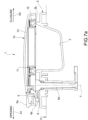
figures 7a and7b are sectional views of the dispenser infigure 1 , which illustrate two different movement steps when the cover is released from the closed position; -
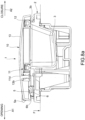
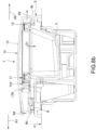
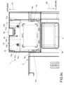
figures 8a and8b are sectional views of the dispenser infigure 1 , which illustrate two different movement steps when the cover is brought to the closed position; -
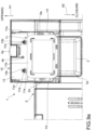
figures 9a-9c are plan views of the dispenser infigure 1 , with the shell of the cover shown in transparency, which illustrate three different movement steps when the cover reaches the open position; -
figures 10 and 11 are, respectively, an exploded view of the cover and a perspective view of the dispenser body showing a sliding guide associated with one side of the cover; -
figures 12 and 13 are an exploded view of the cover and a perspective view of the dispenser body showing a sliding guide associated with a second side of the cover; and -
figure 14 is a sectional view showing the operation of the sliding guide infigures 12 and 13 , and -
figures 15 and 16 are respectively a perspective view of the cover and a perspective view of the dispenser body showing a sliding guide according to an alternative embodiment. - Figures la and 1b show a dispenser of washing agents, indicated as a whole with
reference numeral 1. Such adispenser 1 is adapted to be mounted to a wall F, schematically shown infigures 7a-7b and8a-8b , which delimits a washing chamber of a washing machine, in particular a dishwasher, in further detail to the movable door of the dishwasher that allows access to the washing chamber (as known in the art). - The example shows a combined dispenser configured to supply two different washing agents, for example a detergent and a rinse aid agent. This configuration is in no way essential for the purposes of the invention, it being sufficient for the dispenser to comprise at least one receptacle for washing agents configured to be closed by a sliding cover. The following description will therefore refer to a single receptacle and to the associated cover.
- In the embodiment shown, the
dispenser 1 comprises adispenser body 2 of molded plastic material. - In the
dispenser body 2 areceptacle 3 is formed for a washing agent essentially in the form of a tray, to which acover 10 of the sliding type is associated, mounted to thedispenser body 2, which will be described in more detail below. - The
cover 10 is movable in a guided manner with respect to thedispenser body 2 between a closed position (shown infigure 7a ) and an open position (shown infigures 1 and9c ), in which thecover 10 closes and opens thereceptacle 3. In particular, thecover 10 is slidable in the direction of the arrows A1 and A2 represented in particular infigures 7a-7b ,8a-8b and9a-9c . To this end, sliding guides interposed between thecover 10 and thedispenser body 2 are associated to the lateral sides of thecover 10, which will be described in more detail below. - An elastic return member, such as for example a spring 4, is associated with the
cover 10. This elastic return member 4 is arranged so as to urge thecover 10 towards the open position. In the illustrated example, the elastic return member 4, which for convenience is shown only infigure 1b , is a torsion spring. - When the
cover 10 is in the closed position (figure 7a ), a latching system holds thecover 10 in this position against the action of the elastic return element 4 which would tend to bring thecover 10 to the open position. - With reference to
figures 7a-7b and8a-8b , the latching system comprises anengagement member 5 elastically stressed and arranged on thecover 10, and arelease member 6 arranged on thedispenser body 2. - In the example shown in the drawings, the
release member 6 is designed as an oscillating lever associated with ashaft 6a mounted rotatably to thedispenser body 2. The axis of rotation of thelever 6 is indicated with z in the figures, and extends in a direction substantially orthogonal to the direction of sliding of thecover 10. - In a per se known manner, the
release member 6 is operatively connected to an electrically actuated actuator (not shown), such as a solenoid actuator or the like. Thanks to this connection, therelease member 6 is able to move between a deactivated or de-energized configuration (shown in the figures), in which afree end 6b is configured to be engaged by the latchingmember 5 when the cover is in the closed position, and a temporary activated or excited configuration (not visible in the figures), in which thefree end 6b of therelease member 6 releases the latchingmember 11 allowing the cover to pass from the closed position to the open position, due to the associated return spring 4. - In the example shown, the latching
member 5 is made in one piece with an openingmember 5a manually operated disposed on thecover 10, such as a push-button operated with a lifting thereof (pull button). In a manner known per se, the latchingmember 5 and the relative opening member are urged towards a rest position (represented in general in the figures) by an elastic return member (not shown) interposed between the latchingmember 5 and thecover 10. Therefore, the openingmember 5a is operable manually, against the action of this elastic return element, to disengage the latchingmember 5 from thefree end 6b of therelease member 6 when therelease member 6 is in the deactivated condition, allowing thecover 5 to pass from the closed position to the open position under the effect of the elastic return member 4. The arrangement described above with respect to the latchingmember 5 and therelease member 6 may be different from the one described above, according to the multiple configurations of the latching systems known to the man skilled in the art. - With reference to
figures 2 and4-6 , thecover 10 comprises aframe 11 and ashell 13 assembled to theframe 11 and covering theframe 11. As will be clarified below, thecover 10 is configured in such a way that theshell 13 is movable in a limited manner with respect to theframe 11 along the sliding direction, and preferably also along a direction orthogonal to the sliding direction. For the purposes of the present invention, by movable "in a limited manner" it is meant that the shell is able to move with respect to the frame by an extent, for example around one mm, much smaller than that of the stroke between the open position and the closed position of the cover, which is generally a few centimeters. - The
frame 11 and theshell 13 may be made of different plastic material. In particular, theframe 11 may be made of plastic material having a friction coefficient with the material of thedispenser body 2 lower than the friction coefficient of the plastic material of theshell 13 with the material of thedispenser body 2. For example, the dispenser body and the shell may be made of polypropylene (PP), and the frame of polyoxymethylene (POM). - In the illustrated example, the
frame 11 comprises a pair oflateral elements 11a along which guide elements for the sliding guides are formed (which will be described in more detail below), and acentral part 11b which interconnects thelateral elements 11a of theframe 11. In a seat formed in thecentral part 1 1b of theframe 11 agasket 12 is mounted, which is configured to be engaged by a protrudingedge 3a of thereceptacle 3 of thedispenser body 2 when the cover is in the closed position. - The
central part 1 lb of theframe 11 has an extension in the sliding direction smaller than that of thelateral elements 11a of theframe 11. In particular, thelateral elements 11a extend beyond thecentral part 11b of theframe 11 towards the open position of thecover 10. - The
shell 13 of thecover 10 has an extension in the sliding direction approximately equal to that of the lateral elements of theframe 11. Theframe 11 essentially performs the functions of sealing and guiding thecover 10, cooperating with thedispenser body 2. On the other hand, theshell 13 performs, in addition to a function of aesthetic coverage, also that of supporting the latchingmember 5 and the relative manually operated openingmember 5a, as shown infigures 7a-7b and8a-8b . The latching of thecover 10 to thedispenser body 2 therefore takes place through theshell 13. Moreover, the elastic return element 4 which urges thecover 10 is arranged so as to act between the dispenser body 1b and theshell 13. For example, as shown infigure 1b , the elastic return element 4 has an end fixed to aseat 4a formed on thedispenser body 2, and an opposite end fixed to aseat 4b formed on the shell (visible for example in thefigure 2 ). - In the illustrated example, the possibility of relative movement between the
shell 13 and theframe 11 is obtained thanks to the fact that at the opposite ends of each of thelateral elements 11 there are formedcoupling projections 11c inserted in relative seats orcoupling slits 13a formed on the shell. The arrangement of the projections and the relative slits is such as to allow theframe 11 and theshell 13 to remain joined, while leaving the possibility of having a relative motion between the two components. - Moreover, the
frame 11 is connected to the shell through at least onedeformable connection element 11d of material having a lower stiffness than the material(s) of theshell 13 and of theframe 11. In the example shown, thedeformable connection element 11d is made as a pair of sleeves integral with theframe 11, and in whichrespective rods 13a formed in theshell 13 and projecting from theshell 13 in a direction substantially orthogonal to the sliding direction of thecover 10 are inserted. Thedeformable sleeves 11d are made in one piece with thegasket 12 arranged on theframe 11, being connected thereto it bybridges 1 le which pass through slits formed in a wall of the seat of thegasket 12. According to an alternative embodiment, the deformable sleeves may be made as elements separated from thegasket 12. Thedeformable sleeves 11d are arranged on one side of thecentral part 11b of theframe 11 facing the open position of thecover 10. - By virtue of the arrangement described above, when the
release member 6 is operated with thecover 10 in the closed position (figure 7a ) to free thecover 10, theshell 13 starts to move before theframe 11 , that is when theframe 11 is still stationary (the relative motion of theshell 13 with respect to theframe 11 is highlighted by the arrow X1 infigure 7b ). This means that, if thegasket 12 has remained attached to the edge of thereceptacle 3 of thedispenser body 2, for example due to the presence of dirt or detergent placed inside thereceptacle 3 which has reacted at least partially with water, forming an adhesive substance between theseal 12 and the edge of thereceptacle 3a, there is still a displacement of the receptacle and therefore of therelative latching member 5. This prevents therelease member 6 from engaging again with the latchingmember 5, when the actuator which actuates the release member is de-energized. In this way it is possible that the cover becomes free some time later when the undesired adhesion between the gasket and the edge of the receptacle ends its effect, for example due to the washing water which washes away the dirt or detergent present between the gasket and the edges of the receptacle, or simply because at a certain moment the force of adhesion is no longer able to overcome the continuous action of the elastic force of the return member 4. - Moreover, when the
cover 10 is brought back to the closed position (figures 8a and8b ) manually by a user, the final position which is reached by the frame 11 (figure 8a ), and therefore the position of thegasket 12 with respect to thereceptacle 3, is determined by a stop (23a, 33; shown infigure 14 and discussed below) provided on the sliding guides. Beyond this position, theshell 13 continues to move (arrow X2 infigure 8b ) towards the closed position until engagement between the latchingmember 5 arranged on theshell 13 and therelease member 6 arranged on thedispenser body 2 is achieved. Moreover, in this closed condition thesleeve 11d is compressed radially (as indicated infigure 8b ) and realizes a further preloading of the shell with respect to the frame which helps to generate the relative motion between these two elements in addition to the spring 4 in the moment of release by therelease member 6. During this step of relative closing movement along the sliding direction it may be provided that there is also a relative movement of lowering of theframe 11 towards the dispenser body 2 (arrow Z1 infigure 8b ), with the consequent achievement of an increase in the tightening on thegasket 12. This further movement can be obtained for example by coupling the shell with the frame by means of an inclined plane. - When the
cover 10 is brought from the closed position to the open position due to the elastic force of the return spring 4 (figures 9a-9c ), initially theframe 11 and theshell 13 of the cover move together (figure 9a ). On thedispenser body 2 there is astop 2a (in the illustrated example, two stops) adapted to be engaged by acorresponding engagement surface 11f (in the example, two engagement surfaces) formed on theframe 11, which determines the opening position of thecover 10. As a matter of graphic simplicity, thestop 2a is not shown in all figures. When theengagement surface 11f strikes thecorresponding stop 2a, theframe 11 stops (figure 9b ), while the shell continues by inertia by its own forward movement causing a radial crushing at the front and at the rear an elongation of thedeformable sleeves 11d, as well as an elongation of thebridges 11e which connect them to the gasket 12 (figure 9c ). The combined effect of the fact that only a part of the cover (the frame) "rigidly" impacts the stop and that the deformable connection between the shell and the frame acts as a damper, allows obtaining a damping of the noise linked to the impact between stop and frame without compromising the precise positioning of the cover with respect to the dispenser body. - With reference to
figures 10-14 , the dispenser sliding guides described above are now described. As will be appreciated below, the conformation of the sliding guides does not depend on the two-part structure of the cover described above. Such sliding guides could therefore also be applied in a dispenser comprising a conventional one-piece cover or other types of cover. -
Figures 10 and 11 show a side of thecover 10 and acorresponding wall 2b of thedispenser body 2 facing towards that side of thecover 10. On this side, the sliding guide comprisesfirst guide elements wall 2b of thedispenser body 2, andsecond guide elements cover 10, in particular on the correspondinglateral element 11a of theframe 11. The first guide elements comprise, according to the direction that goes from the open position to the closed position of thecover 10, a guidingpin 21 and a guidinggroove 22 having anend 22a facing the closed position of thecover 10 which is inclined towards thedispenser body 2. The second guide elements comprise, according to the direction from the open position to the closed position of thecover 10, a guidedgroove 31 and a guidedpin 32. During the movement of thecover 10 between the open position and the closed position, the guidingpin 21 is engaged in the guidedgroove 31 and the guidedpin 32 is engaged in the guidinggroove 22. -
Figures 12 and 13 show the side of thecover 10 and acorresponding wall 2c of thedispenser body 2 facing towards that side of thecover 10. On this side, the sliding guide comprisesfirst guide elements wall 2c of thedispenser body 2, andsecond guide elements cover 10, in particular on the correspondinglateral element 11a of theframe 11. The first guide elements comprise, according to the direction that goes from the open position to the closed position of thecover 10, a guidingprojection 23, aninterruption gap 24 and a guidingrib 25 having anend 25a facing the closed position of thecover 10 which is inclined towards thedispenser body 2. The second guide elements comprise, according to the direction from the open position to the closed position of thecover 10, astop projection 33, a guidedgroove 34 and a guidedprojection 35. During the movement of thecover 10 between the open position and the closed position, one or the other of said guidingprojections 23 and guidingrib 25 is engaged between the guidedrib 34 and the guidedprojection 35, as shown infigure 14 . Thestop projection 33 is adapted to cooperate with astop surface 23a of the guidingprojection 23 at the closing position of thecover 10. - Although the example described above concerns a cover with a frame assembled together and provided with movement relative to one another, the invention also contemplates a cover in which the frame and the shell are more generally joined to one another by shape, strength or material coupling, or a cover in which the frame and shell are integral, i.e. rigidly constrained to one another.
- For example, in an alternative embodiment the
cover 10 can also be made in a single component in which theframe 11 and theshell 13 are made of two different materials co-molded or made of plastic of two different types and bi-injected in the same mold. In this way, although it does not solve the drawback of facilitating the opening of the cover, it is possible to vary the coefficient of friction of the frame 11 (or of the guides made thereon) with respect to the friction coefficient of theshell 13, so as to obtain a reduction of the friction for the guides. - In a further alternative embodiment the
cover 10 can be made withframe 11 andshell 13 produced separately in two different materials and then fixed with a fixed connection to each other, for example by welding or gluing, so that thecover 10 is a single monolithic element made of 2 components. Also in this case, even if the problem of failure to open due to adhesion of the detergent to the gasket is not solved, a cover is made with sliding guides made on the frame which can be of a material with a friction coefficient lower than the friction coefficient of the shell. -
Figures 15 and 16 show an embodiment of the alternative sliding guide with respect to that illustrated infigures 10 and 11 . The same reference numbers have been assigned to elements corresponding to the above embodiment. In this embodiment, the sliding guide comprises first guide elements 21', 22', 23' arranged on thewall 2b of thedispenser body 2, and second guide elements 31', 32' arranged on the corresponding side of thecover 10, in particular on the correspondinglateral element 11a of theframe 11. The first guide elements comprise, according to the direction that goes from the open position to the closed position of thecover 10, a pair of guiding projections 21', 22' arranged at different distances from a bottom surface of thedispenser body 2 and a guiding groove 23' having anend 23a' facing the closed position of thecover 10 which is inclined towards thedispenser body 2. The second guide elements comprise, according to the direction from the open position to the closed position of thecover 10, a guided rib 31' and a guided pin 32'. During the movement of thecover 10 between the open position and the closed position, the guided rib 31' is engaged between the pair of guiding projections 21', 22' and the guided pin 32' is engaged in the guiding groove 23'. - Of course, without altering the principle of the invention, the embodiments and the construction details may vary widely with respect to those described and illustrated purely by way of non-limiting example, without thereby departing from the scope of the invention as defined in the appended claims.
Claims (11)
- A washing agent dispenser for a washing machine, in particular a dishwasher, includinga dispenser body (2) configured to be mounted to a wall (F) delimiting a washing chamber of the washing machine, said dispenser body having a receptacle (3) adapted to contain a washing agent,a cover (10) mounted in a guided manner to the dispenser body (2) in such a way to be movable relative to the dispenser body along a sliding direction, between a closed position in which the receptacle (3) is closed by the cover (10) and an open position in which the receptacle (3) is open, andsliding guides interposed between the cover (10) and the dispenser body (2), and comprising first guide elements (21, 22, 23, 25; 21', 22', 23') arranged on the dispenser body (2) and second guide elements (31, 32, 33, 34, 35; 31', 32') arranged on the cover (10) and coupled to the first guide elements (21, 22, 23, 25; 21', 22', 23'),wherein the cover (10) comprises a frame (11) carrying the second guide elements (31, 32, 33, 34, 35; 31', 32') and a shell (13) assembled or joined to the frame (11),wherein a gasket (12) adapted to engage an edge (3a) of the receptacle (3) of the dispenser body (2) is arranged on the frame (11),wherein the dispenser further comprises a latching system interposed between the shell (13) and the dispenser body (2) and configured to hold the cover (10) in the closed position, said latching system being operable to release the cover (10) allowing the cover to move from the closed position to the open position,the dispenser being characterized in that the frame (11) is connected to the shell (13) by means of at least one deformable connection element (11d) of material having lower stiffness than the material(s) of the shell (13) and the frame (11), said deformable connection element being arranged in such a way that the shell (13) is movable in a limited manner relative to the frame (11) along the sliding direction, the shell (13) being movable with respect to the frame (11) by an extent much smaller than that of the stroke between the open position and the closed position of the cover.
- A dispenser according to claim 1, wherein the cover (10) is configured in such a way that the shell (13) is movable in a limited manner relative to the frame (11) along a direction orthogonal to the sliding direction.
- A dispenser according to any of the preceding claims, wherein when the cover (10) is brought into the closed position the frame (11) stops before the shell (13) does.
- A dispenser according to any of the preceding claims, wherein the frame (11) and the shell (13) are made of different plastic materials.
- A dispenser according to claim 4, wherein the frame (11) is made of plastic material having a friction coefficient lower than the friction coefficient of the plastic material of the shell (13).
- A dispenser according to any of the preceding claims, wherein the frame (11) comprises a pair of lateral elements (11a) along which the second guide elements (31, 32, 33, 34, 35; 31', 32') are formed, and a central part (11b) that interconnects the lateral elements (11a) of the frame (11) and carries the gasket (12).
- A dispenser according to any of the preceding claims, wherein the deformable connection element (11d) is formed as a sleeve fixed to the frame (11), and in which there is fitted a rod (13b) formed in the shell (13) and projecting from the shell in a direction substantially orthogonal to the sliding direction of the cover (10).
- A dispenser according to any of the preceding claims, wherein the deformable connection element (11d) is formed as a single piece with a gasket (12) arranged on the frame (11) and adapted to engage an edge (3a) of the receptacle (3) of the dispenser body (2).
- A dispenser according to any of the preceding claims, wherein the frame (11) comprises a pair of lateral elements (11a) along which the second guide elements (31, 32, 33, 34, 35; 31', 32') are formed, and a central part (11b) that interconnects the lateral elements (11a) of the frame (11) and carries a gasket (12) adapted to engage an edge (3a) of the receptacle (3) of the dispenser body (2), and wherein the deformable connection element (11d) is arranged on a side of the central part (11b) of the frame (11) facing in a direction from the closed position towards the open position of the cover (10).
- A dispenser according to any of the preceding claims, wherein on at least one wall (2c) of the dispenser body (2) facing towards one side of the cover (10), the first guide elements comprise, according to a direction running from the open position to the closed position of the cover (10), a guiding projection (23), an interruption gap (24) and a guiding rib (25) having an end (25a) facing in a direction from the open position towards the closed position of the cover (10) which is inclined towards the dispenser body (2), and wherein on at least one side of the cover (10) the second guide elements comprise, according to a direction running from the open position to the closed position of the cover (10), a stop projection (33), a guided rib (34) and a guided projection (35), and wherein during motion of the cover (10) between the open position and the closed position one or the other of said guiding projection and guiding rib is engaged between the guided rib (34) and the guided projection (35).
- A dispenser according to any of the preceding claims, wherein on at least one wall (2b) of the dispenser body (2) facing towards one side of the cover (10) a first guide elements comprise, according to a direction running from the open position to the closed position of the cover (10), a pair of guiding projections (21', 22') and a guiding groove (23'), and wherein on at least one side of the cover (10) the second guide elements comprise, according to a direction running from the open position to the closed position of the cover (10), a guided rib (31') and a guided pin (32'), and wherein during motion of the cover (10) between the open position and the closed position the guided rib (31') is engaged between the pair of guiding projections (21', 22') and the guided pin (32') is engaged in the guiding groove (23').
Applications Claiming Priority (2)
| Application Number | Priority Date | Filing Date | Title |
|---|---|---|---|
| IT102018000008272A IT201800008272A1 (en) | 2018-08-31 | 2018-08-31 | Washing agent dispenser for a washing machine, in particular a dishwashing machine. |
| PCT/IB2019/057309 WO2020044292A1 (en) | 2018-08-31 | 2019-08-30 | A washing agent dispenser for a washing machine, particularly for a dishwasher |
Publications (2)
| Publication Number | Publication Date |
|---|---|
| EP3843606A1 EP3843606A1 (en) | 2021-07-07 |
| EP3843606B1 true EP3843606B1 (en) | 2024-10-16 |
Family
ID=64316791
Family Applications (1)
| Application Number | Title | Priority Date | Filing Date |
|---|---|---|---|
| EP19783655.4A Active EP3843606B1 (en) | 2018-08-31 | 2019-08-30 | A washing agent dispenser for a washing machine, particularly for a dishwasher |
Country Status (4)
| Country | Link |
|---|---|
| EP (1) | EP3843606B1 (en) |
| IT (1) | IT201800008272A1 (en) |
| PL (1) | PL3843606T3 (en) |
| WO (1) | WO2020044292A1 (en) |
Citations (1)
| Publication number | Priority date | Publication date | Assignee | Title |
|---|---|---|---|---|
| US20180360294A1 (en) * | 2015-06-18 | 2018-12-20 | Eltek S.P.A. | Washing agent dispenser for household washing machines, in particular dishwashers |
Family Cites Families (4)
| Publication number | Priority date | Publication date | Assignee | Title |
|---|---|---|---|---|
| ITTO20060259A1 (en) * | 2006-04-07 | 2007-10-08 | Elbi Int Spa | DEVICE FOR DISTRIBUTING A WASHING AGENT IN A WASHING MACHINE, IN PARTICULAR A DISHWASHER MACHINE. |
| CN204690389U (en) * | 2015-05-08 | 2015-10-07 | Tcl智能科技(合肥)有限公司 | Detergent box and washing machine |
| CN204744063U (en) * | 2015-05-12 | 2015-11-11 | 俞云良 | Detergent storehouse lid slider of dish washer distributor |
| IT201600121779A1 (en) * | 2016-12-01 | 2018-06-01 | Elbi Int Spa | Washing agent dispenser for a washing machine, in particular a dishwasher. |
-
2018
- 2018-08-31 IT IT102018000008272A patent/IT201800008272A1/en unknown
-
2019
- 2019-08-30 PL PL19783655.4T patent/PL3843606T3/en unknown
- 2019-08-30 EP EP19783655.4A patent/EP3843606B1/en active Active
- 2019-08-30 WO PCT/IB2019/057309 patent/WO2020044292A1/en not_active Ceased
Patent Citations (1)
| Publication number | Priority date | Publication date | Assignee | Title |
|---|---|---|---|---|
| US20180360294A1 (en) * | 2015-06-18 | 2018-12-20 | Eltek S.P.A. | Washing agent dispenser for household washing machines, in particular dishwashers |
Also Published As
| Publication number | Publication date |
|---|---|
| WO2020044292A1 (en) | 2020-03-05 |
| EP3843606A1 (en) | 2021-07-07 |
| PL3843606T3 (en) | 2025-02-10 |
| IT201800008272A1 (en) | 2018-12-01 |
Similar Documents
| Publication | Publication Date | Title |
|---|---|---|
| KR101762933B1 (en) | Dispenser for dispensing a washing agent in a washing machine, particularly a dishwasher | |
| US20080185849A1 (en) | Closing mechanism for a household appliance | |
| US7690700B2 (en) | Door latch device for a domestic appliance, in particular for a dish washer | |
| EP1972715B1 (en) | Locking device for the closing lid of washing and drying machines | |
| EP1450661B1 (en) | Dispenser device particularly for dishwashing machines | |
| KR101555478B1 (en) | washing machine door assembling structure and assembling method of the same | |
| EP1379156A1 (en) | Washing agents dispenser device for a dishwashing machine | |
| US10213089B2 (en) | Washing agent dispenser for a washing machine, in particular a dishwasher | |
| EP2007268B1 (en) | Device for dispensing a washing agent in a washing machine, particularly a dishwasher | |
| CN113038861B (en) | Door locking device for household appliances, especially dishwashers, and household appliances provided with the door locking device | |
| EP2680736B1 (en) | An integrated device for dispensing washing agents for a washing machine, in particular for a dishwashing machine | |
| EP3843606A1 (en) | A washing agent dispenser for a washing machine, particularly for a dishwasher | |
| EP2798117B1 (en) | A laundry washing and/or drying machine | |
| JP4660347B2 (en) | Drum washing machine | |
| KR20010039835A (en) | Switch device | |
| CZ159096A3 (en) | Connecting device arranged between a suction hose and a suction unit | |
| JP6309106B2 (en) | Belt buckle for seat belt system | |
| JP2007196005A (en) | dishwasher | |
| JP2734999B2 (en) | Suspension rail mechanism | |
| JP2005095669A (en) | dishwasher | |
| KR20230171221A (en) | Armrest for an automobile having friction hinge | |
| US20190335975A1 (en) | Device for dispensing cleaning agents | |
| KR20110045742A (en) | Multi-stage hinge structure of dishwasher door and opening method of dishwasher door | |
| EP2458057B1 (en) | Appliance handle assembly and method for mounting such assembly to an appliance | |
| US20260125931A1 (en) | Home appliance door lock device |
Legal Events
| Date | Code | Title | Description |
|---|---|---|---|
| STAA | Information on the status of an ep patent application or granted ep patent |
Free format text: STATUS: UNKNOWN |
|
| STAA | Information on the status of an ep patent application or granted ep patent |
Free format text: STATUS: THE INTERNATIONAL PUBLICATION HAS BEEN MADE |
|
| STAA | Information on the status of an ep patent application or granted ep patent |
Free format text: STATUS: REQUEST FOR EXAMINATION WAS MADE |
|
| PUAI | Public reference made under article 153(3) epc to a published international application that has entered the european phase |
Free format text: ORIGINAL CODE: 0009012 |
|
| 17P | Request for examination filed |
Effective date: 20210323 |
|
| AK | Designated contracting states |
Kind code of ref document: A1 Designated state(s): AL AT BE BG CH CY CZ DE DK EE ES FI FR GB GR HR HU IE IS IT LI LT LU LV MC MK MT NL NO PL PT RO RS SE SI SK SM TR |
|
| DAV | Request for validation of the european patent (deleted) | ||
| DAX | Request for extension of the european patent (deleted) | ||
| STAA | Information on the status of an ep patent application or granted ep patent |
Free format text: STATUS: EXAMINATION IS IN PROGRESS |
|
| 17Q | First examination report despatched |
Effective date: 20230717 |
|
| GRAP | Despatch of communication of intention to grant a patent |
Free format text: ORIGINAL CODE: EPIDOSNIGR1 |
|
| STAA | Information on the status of an ep patent application or granted ep patent |
Free format text: STATUS: GRANT OF PATENT IS INTENDED |
|
| INTG | Intention to grant announced |
Effective date: 20240516 |
|
| RAP3 | Party data changed (applicant data changed or rights of an application transferred) |
Owner name: BITRON POLAND SP. Z O.O. |
|
| GRAS | Grant fee paid |
Free format text: ORIGINAL CODE: EPIDOSNIGR3 |
|
| GRAA | (expected) grant |
Free format text: ORIGINAL CODE: 0009210 |
|
| STAA | Information on the status of an ep patent application or granted ep patent |
Free format text: STATUS: THE PATENT HAS BEEN GRANTED |
|
| AK | Designated contracting states |
Kind code of ref document: B1 Designated state(s): AL AT BE BG CH CY CZ DE DK EE ES FI FR GB GR HR HU IE IS IT LI LT LU LV MC MK MT NL NO PL PT RO RS SE SI SK SM TR |
|
| REG | Reference to a national code |
Ref country code: GB Ref legal event code: FG4D |
|
| REG | Reference to a national code |
Ref country code: CH Ref legal event code: EP Ref country code: DE Ref legal event code: R096 Ref document number: 602019060536 Country of ref document: DE |
|
| REG | Reference to a national code |
Ref country code: IE Ref legal event code: FG4D |
|
| REG | Reference to a national code |
Ref country code: LT Ref legal event code: MG9D |
|
| REG | Reference to a national code |
Ref country code: NL Ref legal event code: MP Effective date: 20241016 |
|
| REG | Reference to a national code |
Ref country code: AT Ref legal event code: MK05 Ref document number: 1732217 Country of ref document: AT Kind code of ref document: T Effective date: 20241016 |
|
| PG25 | Lapsed in a contracting state [announced via postgrant information from national office to epo] |
Ref country code: NL Free format text: LAPSE BECAUSE OF FAILURE TO SUBMIT A TRANSLATION OF THE DESCRIPTION OR TO PAY THE FEE WITHIN THE PRESCRIBED TIME-LIMIT Effective date: 20241016 |
|
| PG25 | Lapsed in a contracting state [announced via postgrant information from national office to epo] |
Ref country code: NL Free format text: LAPSE BECAUSE OF FAILURE TO SUBMIT A TRANSLATION OF THE DESCRIPTION OR TO PAY THE FEE WITHIN THE PRESCRIBED TIME-LIMIT Effective date: 20241016 |
|
| PG25 | Lapsed in a contracting state [announced via postgrant information from national office to epo] |
Ref country code: HR Free format text: LAPSE BECAUSE OF FAILURE TO SUBMIT A TRANSLATION OF THE DESCRIPTION OR TO PAY THE FEE WITHIN THE PRESCRIBED TIME-LIMIT Effective date: 20241016 Ref country code: IS Free format text: LAPSE BECAUSE OF FAILURE TO SUBMIT A TRANSLATION OF THE DESCRIPTION OR TO PAY THE FEE WITHIN THE PRESCRIBED TIME-LIMIT Effective date: 20250216 Ref country code: PT Free format text: LAPSE BECAUSE OF FAILURE TO SUBMIT A TRANSLATION OF THE DESCRIPTION OR TO PAY THE FEE WITHIN THE PRESCRIBED TIME-LIMIT Effective date: 20250217 |
|
| PG25 | Lapsed in a contracting state [announced via postgrant information from national office to epo] |
Ref country code: FI Free format text: LAPSE BECAUSE OF FAILURE TO SUBMIT A TRANSLATION OF THE DESCRIPTION OR TO PAY THE FEE WITHIN THE PRESCRIBED TIME-LIMIT Effective date: 20241016 |
|
| PG25 | Lapsed in a contracting state [announced via postgrant information from national office to epo] |
Ref country code: BG Free format text: LAPSE BECAUSE OF FAILURE TO SUBMIT A TRANSLATION OF THE DESCRIPTION OR TO PAY THE FEE WITHIN THE PRESCRIBED TIME-LIMIT Effective date: 20241016 |
|
| PG25 | Lapsed in a contracting state [announced via postgrant information from national office to epo] |
Ref country code: ES Free format text: LAPSE BECAUSE OF FAILURE TO SUBMIT A TRANSLATION OF THE DESCRIPTION OR TO PAY THE FEE WITHIN THE PRESCRIBED TIME-LIMIT Effective date: 20241016 |
|
| PG25 | Lapsed in a contracting state [announced via postgrant information from national office to epo] |
Ref country code: NO Free format text: LAPSE BECAUSE OF FAILURE TO SUBMIT A TRANSLATION OF THE DESCRIPTION OR TO PAY THE FEE WITHIN THE PRESCRIBED TIME-LIMIT Effective date: 20250116 |
|
| PG25 | Lapsed in a contracting state [announced via postgrant information from national office to epo] |
Ref country code: GR Free format text: LAPSE BECAUSE OF FAILURE TO SUBMIT A TRANSLATION OF THE DESCRIPTION OR TO PAY THE FEE WITHIN THE PRESCRIBED TIME-LIMIT Effective date: 20250117 Ref country code: AT Free format text: LAPSE BECAUSE OF FAILURE TO SUBMIT A TRANSLATION OF THE DESCRIPTION OR TO PAY THE FEE WITHIN THE PRESCRIBED TIME-LIMIT Effective date: 20241016 Ref country code: LV Free format text: LAPSE BECAUSE OF FAILURE TO SUBMIT A TRANSLATION OF THE DESCRIPTION OR TO PAY THE FEE WITHIN THE PRESCRIBED TIME-LIMIT Effective date: 20241016 |
|
| PG25 | Lapsed in a contracting state [announced via postgrant information from national office to epo] |
Ref country code: RS Free format text: LAPSE BECAUSE OF FAILURE TO SUBMIT A TRANSLATION OF THE DESCRIPTION OR TO PAY THE FEE WITHIN THE PRESCRIBED TIME-LIMIT Effective date: 20250116 |
|
| PG25 | Lapsed in a contracting state [announced via postgrant information from national office to epo] |
Ref country code: SM Free format text: LAPSE BECAUSE OF FAILURE TO SUBMIT A TRANSLATION OF THE DESCRIPTION OR TO PAY THE FEE WITHIN THE PRESCRIBED TIME-LIMIT Effective date: 20241016 |
|
| PG25 | Lapsed in a contracting state [announced via postgrant information from national office to epo] |
Ref country code: DK Free format text: LAPSE BECAUSE OF FAILURE TO SUBMIT A TRANSLATION OF THE DESCRIPTION OR TO PAY THE FEE WITHIN THE PRESCRIBED TIME-LIMIT Effective date: 20241016 |
|
| REG | Reference to a national code |
Ref country code: DE Ref legal event code: R097 Ref document number: 602019060536 Country of ref document: DE |
|
| PG25 | Lapsed in a contracting state [announced via postgrant information from national office to epo] |
Ref country code: EE Free format text: LAPSE BECAUSE OF FAILURE TO SUBMIT A TRANSLATION OF THE DESCRIPTION OR TO PAY THE FEE WITHIN THE PRESCRIBED TIME-LIMIT Effective date: 20241016 |
|
| PG25 | Lapsed in a contracting state [announced via postgrant information from national office to epo] |
Ref country code: RO Free format text: LAPSE BECAUSE OF FAILURE TO SUBMIT A TRANSLATION OF THE DESCRIPTION OR TO PAY THE FEE WITHIN THE PRESCRIBED TIME-LIMIT Effective date: 20241016 |
|
| PG25 | Lapsed in a contracting state [announced via postgrant information from national office to epo] |
Ref country code: SK Free format text: LAPSE BECAUSE OF FAILURE TO SUBMIT A TRANSLATION OF THE DESCRIPTION OR TO PAY THE FEE WITHIN THE PRESCRIBED TIME-LIMIT Effective date: 20241016 |
|
| PG25 | Lapsed in a contracting state [announced via postgrant information from national office to epo] |
Ref country code: IT Free format text: LAPSE BECAUSE OF FAILURE TO SUBMIT A TRANSLATION OF THE DESCRIPTION OR TO PAY THE FEE WITHIN THE PRESCRIBED TIME-LIMIT Effective date: 20241016 |
|
| PLBE | No opposition filed within time limit |
Free format text: ORIGINAL CODE: 0009261 |
|
| STAA | Information on the status of an ep patent application or granted ep patent |
Free format text: STATUS: NO OPPOSITION FILED WITHIN TIME LIMIT |
|
| PG25 | Lapsed in a contracting state [announced via postgrant information from national office to epo] |
Ref country code: SE Free format text: LAPSE BECAUSE OF FAILURE TO SUBMIT A TRANSLATION OF THE DESCRIPTION OR TO PAY THE FEE WITHIN THE PRESCRIBED TIME-LIMIT Effective date: 20241016 |
|
| 26N | No opposition filed |
Effective date: 20250717 |
|
| PGFP | Annual fee paid to national office [announced via postgrant information from national office to epo] |
Ref country code: DE Payment date: 20250822 Year of fee payment: 7 |
|
| PGFP | Annual fee paid to national office [announced via postgrant information from national office to epo] |
Ref country code: PL Payment date: 20250812 Year of fee payment: 7 |
|
| PGFP | Annual fee paid to national office [announced via postgrant information from national office to epo] |
Ref country code: CZ Payment date: 20250715 Year of fee payment: 7 |
|
| REG | Reference to a national code |
Ref country code: CH Ref legal event code: H13 Free format text: ST27 STATUS EVENT CODE: U-0-0-H10-H13 (AS PROVIDED BY THE NATIONAL OFFICE) Effective date: 20260324 |
|
| PG25 | Lapsed in a contracting state [announced via postgrant information from national office to epo] |
Ref country code: MC Free format text: LAPSE BECAUSE OF FAILURE TO SUBMIT A TRANSLATION OF THE DESCRIPTION OR TO PAY THE FEE WITHIN THE PRESCRIBED TIME-LIMIT Effective date: 20241016 |
|
| PG25 | Lapsed in a contracting state [announced via postgrant information from national office to epo] |
Ref country code: LU Free format text: LAPSE BECAUSE OF NON-PAYMENT OF DUE FEES Effective date: 20250830 |
|
| PG25 | Lapsed in a contracting state [announced via postgrant information from national office to epo] |
Ref country code: CH Free format text: LAPSE BECAUSE OF NON-PAYMENT OF DUE FEES Effective date: 20250831 |
|
| GBPC | Gb: european patent ceased through non-payment of renewal fee |
Effective date: 20250830 |