EP3843344A1 - Multi-stage switching topology - Google Patents
Multi-stage switching topology Download PDFInfo
- Publication number
- EP3843344A1 EP3843344A1 EP20210994.8A EP20210994A EP3843344A1 EP 3843344 A1 EP3843344 A1 EP 3843344A1 EP 20210994 A EP20210994 A EP 20210994A EP 3843344 A1 EP3843344 A1 EP 3843344A1
- Authority
- EP
- European Patent Office
- Prior art keywords
- stage
- ports
- switch
- port
- network
- Prior art date
- Legal status (The legal status is an assumption and is not a legal conclusion. Google has not performed a legal analysis and makes no representation as to the accuracy of the status listed.)
- Granted
Links
Images




Classifications
-
- H—ELECTRICITY
- H04—ELECTRIC COMMUNICATION TECHNIQUE
- H04L—TRANSMISSION OF DIGITAL INFORMATION, e.g. TELEGRAPHIC COMMUNICATION
- H04L49/00—Packet switching elements
- H04L49/15—Interconnection of switching modules
- H04L49/1515—Non-blocking multistage, e.g. Clos
-
- H—ELECTRICITY
- H04—ELECTRIC COMMUNICATION TECHNIQUE
- H04L—TRANSMISSION OF DIGITAL INFORMATION, e.g. TELEGRAPHIC COMMUNICATION
- H04L49/00—Packet switching elements
- H04L49/10—Packet switching elements characterised by the switching fabric construction
- H04L49/111—Switch interfaces, e.g. port details
-
- H—ELECTRICITY
- H04—ELECTRIC COMMUNICATION TECHNIQUE
- H04L—TRANSMISSION OF DIGITAL INFORMATION, e.g. TELEGRAPHIC COMMUNICATION
- H04L49/00—Packet switching elements
- H04L49/30—Peripheral units, e.g. input or output ports
- H04L49/3072—Packet splitting
-
- H—ELECTRICITY
- H04—ELECTRIC COMMUNICATION TECHNIQUE
- H04L—TRANSMISSION OF DIGITAL INFORMATION, e.g. TELEGRAPHIC COMMUNICATION
- H04L49/00—Packet switching elements
- H04L49/35—Switches specially adapted for specific applications
- H04L49/356—Switches specially adapted for specific applications for storage area networks
-
- H—ELECTRICITY
- H04—ELECTRIC COMMUNICATION TECHNIQUE
- H04L—TRANSMISSION OF DIGITAL INFORMATION, e.g. TELEGRAPHIC COMMUNICATION
- H04L49/00—Packet switching elements
- H04L49/70—Virtual switches
Definitions
- a folded Clos topology combines a large number of small switches to create a much larger virtual switch.
- a Clos topology consists of two stages. An upper stage (aka spine), and a lower stage. Every switch in the lower stage is connected to every switch in the upper stage. The upper stage allows for information to be transported between switches of the lower stage.
- Folded Clos topology are one way to create large virtual switches from small switches, but there are also other ways, such as a butterfly network or a dragonfly network.
- the upper and/or lower stages of the network can be built from Clos topologies themselves, and can thus consist of several sub-stages.
- the Clos topology can also be said to be made of three stages when an access stage, which connects to a lower stage, is considered.
- a Clos topology includes multiple stages of switches.
- a switch is a hardware device, which includes a number of ports, and interconnects stages of the Clos topology through the ports. The number of ports on the switch is also referred to as the switch radix.
- a spine switch such as a switch in the upper stage, receives information from a switch in the lower stage and sends this information back to the appropriate switch in the lower stage. In this manner, the spine switch allows for the flow of information between switches of the lower stage.
- a typical 4-port switch in the lower stage two ports are used to connect to the upper stage, while the other two ports are free, and can be connected to any network device, such as a host, in the access stage.
- One aspect of the technology provides a system including an upper stage consisting of a plurality of traditional switches, a lower stage consisting of one or more linecards, each of the linecards comprising a plurality of upper ports and a plurality of lower ports, a bottom-up switch, and a top-down switch, wherein all traffic moving from the lower stage to the upper stage is received by a bottom up switch and sent via the bottom up switch to the upper stage, and all traffic moving from the upper stage to the lower stage is received by a top-down switch and sent via the top-down switch to the lower stage.
- a linecard including a plurality of upper ports, a plurality of lower ports, a bottom-up switch, a top-down switch, first connections between the plurality of the lower ports, the bottom up switch, and the upper ports, second connections between the plurality of lower ports, the top-down switch, and the upper ports, and wherein all traffic received at a lower port is sent to the upper port via first connections, and all traffic received at an upper port is sent to a lower port via second connections.
- a linecard including a plurality of upper ports, a plurality of lower ports, a bottom-up switch, a top-down switch, first connections between the plurality of the lower ports, the bottom up switch, and the upper ports, second connections between the plurality of lower ports, the top-down switch, and the upper ports, wherein all traffic received at a lower port is sent to the upper port via first connections, and all traffic received at an upper port is sent to a lower port via second connections, configuring the line card to have an equal number of upper ports and lower ports, configuring the ports to be connected to the bottom-up switch and top-down switch of the linecard, configuring the ports of the bottom-up switch and the top-down switch to have separate connections or interfaces for incoming traffic and outgoing traffic, and using printed circuit boards, metallic wires, or optical wires to create the first connections and/or second connections.
- Another aspect of the technology provides a method to create a folded Clos network, the method including providing an upper stage consisting of traditional switches, providing a lower stage consisting of one or more linecards, providing an access stage consisting of one or more access points, connecting the ports of the traditional switches with the ports of the linecards, connecting the ports of the access points with the ports of the linecards, wherein each of the one or more linecards comprises a plurality of upper ports and a plurality of lower ports, a bottom-up switch, and a top-down switch, measuring the network for network parameters, and optimizing the network for at least one metric based upon the measured network parameters.
- the technology generally relates to a system that provides the ability to double the non-blocking throughput of a folded Clos topology. This is achieved by replacing a conventional switch used in a Clos topology with a new linecard which consists of two switch chips that each forward information uni-directionally.
- the present technology provides a method, system, and apparatus to create a topology including a multi-stage arrangement of independent switches. This topology may be used in various networks, such as data centers, wide area networks (WANs), or local area networks (LANs).
- WANs wide area networks
- LANs local area networks
- the topology addresses an arrangement of switches and linecards in a network, as well as an arrangement of the switches with respect to one another and other network components.
- a novel multi-stage folded Clos network and a linecard for use in a network is disclosed.
- the Clos network can consist of three stages, an access stage, a lower stage, and an upper stage.
- the access stage and the upper stage can include a plurality of switches or conventional access points.
- the lower stage can include a plurality of linecards.
- Each linecard can be made of two switch chips, each of which are connected to the ports of the linecard, and contain the same number of ports.
- Each switch chip can forward information in only one direction and one is used to send direction from the access stage to the upper stage, and the other from the upper stage to the access stage.
- the lower stage can consist of a number of sub-stages, each sub-stage can be entirely of either conventional switches or linecards. Accordingly, compared to a conventional Clos network, the provided network can increase the throughput by any power of 2 by replacing the conventional switches used in the lower stage or sub-stages with linecards.
- a folded Clos network or folded Clos topology combines a number of small switches to create a much larger virtual switch.
- a virtual switch is one that is equivalent to a physical switch with a given number of input and output ports. Every stage of a Clos topology is made of switches.
- a switch is a hardware device - which consists of a number of ports - and interconnects stages of the Clos topology through the ports. The number of ports on the switch is also referred to as the switch radix.
- a switch in the upper stage or spine receives information from a switch in the lower stage and sends this information back to the appropriate switch in the lower stage. In this manner, a switch in the upper stage allows for the flow of information between switches of the lower stage.
- a typical 4-port switch in the lower stage two ports are used to connect to the upper stage, while the other two ports are free, and can be connected to any network device, such as a host. While these principles are discussed on a 4-port switch, the same principle apply when the switches have a larger number of switches, such as for example, an 8-port, 16-port, or 32 port switch.
- the technology provides a technique and a device which can accomplish doubling the throughput of the Clos topology by replacing existing switches in the lower stage with 4-port linecards.
- the new linecard or chassis switch can be made of two two-port switch chips, one of which can be used to forward information from free ports to the upper stage while the other can be used to forward information from the upper stage to free ports. If all conventional switches in the lower stage are replaced with such new linecards, the maximum amount of information which can be sent through the Clos topology can be doubled.
- a key feature of the technology is that other than replacement of conventional switches to linecards, other aspects of the network do not need to be modified to achieve this increased throughput.
- the technology also provides techniques and devices to replace existing switches with any number of ports, such as a k-port switch, with a linecard with the same number of ports, such as a k-port linecard.
- a non-blocking network is one in which the input nodes and output nodes of the network are connected in such a manner that any combination of input and output nodes can communicate with one another at their respective port speeds, when particular conditions are met.
- Port speed is a measure of how fast information can be transmitted or received by a port interface.
- a folded Clos topology can always be configured to be non-blocking when particular conditions are met, making it a suitable topology for network applications involving multiple devices which request and/or send information from one another.
- the throughput of the non-blocking Clos topology is limited by the number of switches comprising the network.
- Fig. 1A illustrates an example of a three stage folded Clos network, such as Clos network 100.
- Fig. 1A illustrates a Clos network with three stages: an upper stage 170, a lower stage 180, and an access stage 190.
- the upper stage 170 can have connections (which are illustrated but not numbered in Fig. 1A ) with lower stage 180 and similarly, the lower stage 180 can have connections with the access stage 190.
- An upper stage, such as the upper stage 170 can include one or more switches, such as switch 110 and switch 120. Although only two switches are depicted in Fig. 1A , the upper stage 170 can be made of any finite number of switches.
- First switch 110 can further contain a number of first ports, such as port 111, and port 112.
- second switch 120 can contain a number of second ports, such as port 121.
- the switches making up the upper stage 170 can contain as many ports as needed to connect with the switches of the lower stage 180.
- Lower stage 180 can include a number of switches, such as switch 130 and switch 140.
- Lower stage 180 can be made from any multitude of switches.
- Switch 130 can further include several ports, some interfacing with upper stage 170, and others interfacing with lower stage 180.
- port 131 can interface with upper stage 170 by connecting with switch 110.
- Other ports can interface with other switches of upper stage 170, allowing for every switch of the middle stage to interface with the upper stage 170.
- port 132 can interface with access stage 190 by connecting with access point 191.
- any access point can connect with any other access point through the Clos network.
- access point 191 can connect with access point 192 through a path routed through access point 191 to switch 130, switch 130 to switch 110, switch 110 to switch 140, and switch 140 to access point 192.
- Links between stages 170, 180, and 190 can be made one or combination of multiple suitable technologies. For example, printed circuit boards, metallic wires, or optical wires can be used to interlink the various stages.
- the switches are depicted with 2 upper ports and 2 lower ports, the switches can contain any number of ports. The switches also allow for information received by any port of the switch to be sent to any other port of the switch, but switches in the lower stage only need to forward to a subset of their ports.
- Fig. 1B is another illustration of a folded Clos topology which illustrates a subset of the set of paths that data flowing through the topology can take. Illustrated in Fig. 1B is Clos network 100. In Fig. 1B upper stage 170, the lower stage 180, and the access stage 190 are connected as illustrated in Fig. 1A , but these intra-connections have been omitted in the figure for clarity.
- One path that data can take is the path illustrated with a loop, such as a path originating in switch 110 of the upper stage 170, through port 111 of switch 110, into port 131 of switch 130, through port 133 of switch 130, and into port 121 of switch 120 of the upper stage 170.
- another path can originate at access point 191 of access stage 190, move to the middle stage 180 through port 132 of switch 130, through port 134 of switch 130, and back to access point 191 of access stage 190.
- Fig. 2 illustrates a device, particularly a linecard 200, according to one aspect of the current technology.
- Linecard 200 can contain for example, four ports, such as port 201, port 202, port 203, and port 204.
- Ports 201-204 can in a manner similar to the ports 131-134 discussed above, be connected to various stages of a network, such as a Clos network, with for example some of the ports being connected to an upper stage of a network while other ports are connected to an access stage.
- port 201 and port 202 can be connected to the upper stage of a network while port 203 and port 204 are connected to an access stage of a network.
- Ports 201-204 can for example be bidirectional ports, that is, the ports 201-204 can both receive and send information to the respective stages to which they are connected.
- port 201 can both receive information from and send information to an upper stage.
- Ports 201-204, and in turn the linecard 200 can further be configured to be connected with one another to only allow information received by a port connected to one stage to send information to ports connected to another stage.
- port 203 which can be connected to an access stage can only send information it receives from the access stage to port 201 and port 202, which are connected to an upper stage.
- each port can be configured to forward information only to the ports which are not connected to the same stage as the port itself.
- Switch chip 210 can contain, for example, two ports, port 211 and port 212.
- switch chip 220 can contain, for example two ports, port 221 and port 222.
- switch chip 210 can be configured to receive information flowing upwards through a network (that is, information flowing from an access stage to an upper stage received by either port connected to an access stage, such as port 203 and port 204) and send this received information upwards (that is, send the information received to a port connected to the upper stage such as port 201 and port 202).
- switch chip 210 can receive this upwards flowing information from port 203 or port 204 at port 211 and port 212 respectively.
- Switch chip 210 can for example, after receiving this information at either port 211 or port 212 forward this information to port 201 or port 202 respectively. Once received at port 201 or port 202, the information can then be forward onwards to the upper stage.
- switch chip 220 can be configured to receive information flowing downwards through a network (that is, information flowing from an upper stage to an access stage received by either port connected to the upper stage, such as port 203 and port 204) and send this received information downwards (that is, send the information received to a port connected to the access stage, such as port 203 and port 204).
- switch chip 220 can receive information flowing downwards from port 201 and port 202 at port 221 and port 222 respectively.
- Switch chip 220 can for example, after receiving this information at either port 221 or port 222, forward this downwards flowing information to port 203 or port 204 respectively.
- Switch chips 210 and 220 can also be described as unidirectional forwarding switches, that is, they only receive and forward information in one direction.
- Switch 210 and switch 220 can also thus be described as "bottom-up” and “top-down” switches, respectively as they receive information from a bottom/lower stage or upper stage respectively, and forward the information up or down through the stages of the network.
- linecard 200 allows for information to be received and sent without information being looped back to the same stage from which the information was received as was the case illustrated in Fig. 1B .
- Linecard 200 does not allow for connections between ports connecting to the same stage of the Clos topology, such as between port 201 and port 202, and between port 203 and port 204. As further explained below, this configuration allows for the radix of linecard 200 to be double that of switch 130.
- the configuration above can be achieved, for example, by physically connecting wires from the port of the linecard, such as linecard 200, to the ports of the switch chips, such as switch chip 210 or switch chip 220.
- Incoming traffic wires can be connected to different linecard ports than the outgoing traffic wires. This can be achieved, for example, if a switch chip has in its ports different electrical wires, socket connections, for traffic that is incoming to the switch chip and traffic that is outgoing from the switch chip.
- the same result can be achieved by configuring the switch chip to either receive or send traffic using software.
- the switch chip and its wires can be patterned onto a printed circuit board in a manner that differentiates the incoming and outgoing traffic.
- Fig. 3 illustrates a representation of some of the data connections within a network according to one aspect of the current technology, network 300.
- Fig. 3 illustrates the equivalent network achieved by replacing a prior art switch, such as switch 130, with a linecard of the present disclosure, such as linecard 200.
- Network 300 can be made of an upper stage 370, lower stage 380, and an access stage 390. Similar to the stages in network 100, the upper stage 370 can consist of a number of switches, and the access stage 390 can be made of a number of access points, such as access point 391.
- the lower stage 380 can be made of a number of line switches, such as line switch 381.
- Components of stages 370, 380, and 390 contain ports to receive and send information which are not illustrated in Fig.
- linecard 381 is depicted as two separate components, linecard 381 is one component which can be, for example, similar to linecard 200 illustrated in Fig. 2 , and is illustrated as a bifurcated switch to show the equivalent number of non-blocking connections.
- network 300 illustrates twice the number of data connections which can simultaneously be utilized in the network.
- linecard 381 has 8 connections to the upper stage as compared to switch 130 of network 100, which only has 4 connections.
- Each linecard in lower stage 380 similarly has double the number of connections when compared to a switch in lower stage 180.
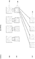
- Fig. 4 illustrates an example of information flowing through a network of the present technology, network 400.
- Network 400 contains an upper stage, such as upper stage 470, made of upper switches, such as such as switch 410 and switch 420, which can be for example 4 port switches; a lower stage, such as lower stage 480, made only of linecards, such as linecards 430 and 440; and an access stage, such as access stage 490 made of access points, such as access point 491 and 492.
- a plurality of bidirectional ports are illustrated in Fig. 4 , such as ports 431-434, ports 441-442, and ports 411, 412, 421, and 422.
- Illustrated in a dotted line with an 'x' is a path that information traveling from upper switch 410 to access point 491 cannot take through linecard 430. Similarly illustrated in a dotted line with an 'x' is a path that information travelling from an access point 492 to switch 420 cannot take through linecard 440. Replacing conventional switches with linecards of the present technology prevents these paths from ever being taken, and allows for the throughput of information through the network to be doubled.
- Fig. 5 illustrates an example of a linecard of the current technology.
- the linecard can consist of a plurality of ports (not labeled), which can to other stages in a network, such as an access stage and an upper stage. All ports receiving information from a first stage, such as an access stage and sending it to a second stage, such as an upper stage, can be connected to a switch chip, such as switch chip 501 (labeled SI). Similarly, all ports receiving information from a second stage, such as an upper stage and sending it to a first stage, such as an access stage, can be connected to a second switch chip, such as switch chip 502 (labeled S2). Switch chips 501 and 502 can contain, for example, the number of ports to which they are connected. Also illustrated in Fig. 5 are exemplary flows of information through switch chips 501 and 502.
- Fig. 5 illustrates an 8 port linecard, with 4 ports connecting to a first stage of a network, and 4 ports connecting to a second stage of a network, and switch chips with 4 ports each
- the configuration of the linecard can be modified to accommodate any number of ports.
- the results above can be generalized.
- n-port switches in the lower stage can be replaced with 2n-port linecards.
- the 2n-port linecard can be made of a set of switch chips, S1 and S2, wherein each switch chip is an n-port switch.
- the throughput of each Clos-topology can be improved by up to a factor of 2 by replacing all n-port switches in the lower stage with 2n-port linecards.
- the lower stage of the Clos network can include additional sub-stages. For example, multiple additional stages can be connected with one another, in pairs, to create the lower stage of the Clos network.
- the conventional switches in the sub-stages can be replaced entirely with linecards.
- the throughput of the network can be increased by a factor of 2 R , where R is the number of sub-stages wherein a conventional switch is replaced with a linecard.
- the throughput of the network will also be increased by a factor of 2 R , where R is the number of sub-stages wherein a conventional switch is replaced with a linecard.
- n-port switches in the lower stage can be replaced with n-port linecards, where the n-port refers to the number of ports of the linecard or switch.
- the n-port linecard can be made of a set of switch chips, such as switch chips S1 and S2, wherein each switch chip has n/2 ports. In this manner, the throughput of each Clos-topology can be improved by a factor of 2 by replacing all n-port switches in a lower stage with n-port linecards.
- the sub-stages can be made of line cards while other stages can be made of conventional switches.
- the throughput of the network can be increased by a factor of 2R, where R is the number of sub-stages made of line cards.
- Fig. 6 illustrates a method 600 according to aspects of the technology.
- a non-blocking Clos topology network can be created which can increase the non-blocking throughput of the network as compared to a network created from conventional switches.
- the network may be any type of network, such as a data center, a LAN, or a WAN, or even a multi-stage processing chip. While various operations of the method are illustrated and described in a particular order, it should be understood that they do not have to be performed in this order. Rather, various operations may be handled in a different order or simultaneously, and operations may also be added or omitted unless otherwise stated.
- Method 600 begins at block 605.
- an access stage can be provided.
- the access stage can consist of access points. Access points can be any suitable device.
- an upper stage can be provided.
- the upper stage such as upper stage 470, can be made of conventional switches.
- a lower stage can be provided, which is made of linecards, such as linecard 200.
- the linecards in this stage can have as many ports as necessary based on the overall configuration of the network. This can be repeated as needed to create a lower stage that consists of multiple sub-stages.
- the various stages of the network can be linked by connecting the ports making up the various stages with any suitable technology.
- Ethernet wires or other optical wires can be used to connect the ports of the switches, devices, and linecards comprising the network.
- the network can be further optimized based on any given parameter. Any suitable parameter can be chosen, such as the latency of the network.
- information can be obtained concerning the network, and based on the obtained information, aspects of the network can be optimized. For example, a particular path can be identified within the network. Optimization can be based on, for example, linear or non-linear optimization methods, including but not limited to Dijkstra's algorithm, machine algorithms, gradient methods, dynamic programming, integer programming, or generalized iterative scaling.
- Information used to optimize a parameter of the system can constitute for example, historic data about the system, or simulated demands on the system. For example, the throughput, latency, or number of connections available to a particular path within the topology may be optimized. For example, only some conventional switches may be replaced with linecards based on the historic data about the system to increase the throughput between start and end points within a network.
- the above-described aspects of the technology may be advantageous in increasing the bandwidth and throughput within a network.
- the throughput of the network can be increased by any power of 2.
- Another key feature of the technology is that other than replacement of conventional switches to linecards, other aspects of the network do not need to be modified to achieve this increased throughput.
- upgrades within existing networks can be made without modifying the manner in which a user of the network interacts or interfaces with the network.
- the examples herein are merely illustrative.
- the described system and method may be implemented over any network, such as the Internet, or any private network connected through a router.
- the network may be a virtual private network operating over the Internet, a local area network, or a wide area network.
- numerous other modifications may be made to the illustrative examples.
Landscapes
- Engineering & Computer Science (AREA)
- Computer Networks & Wireless Communication (AREA)
- Signal Processing (AREA)
- Small-Scale Networks (AREA)
- Data Exchanges In Wide-Area Networks (AREA)
Abstract
Description
- A folded Clos topology combines a large number of small switches to create a much larger virtual switch. A Clos topology consists of two stages. An upper stage (aka spine), and a lower stage. Every switch in the lower stage is connected to every switch in the upper stage. The upper stage allows for information to be transported between switches of the lower stage. Folded Clos topology are one way to create large virtual switches from small switches, but there are also other ways, such as a butterfly network or a dragonfly network. The upper and/or lower stages of the network can be built from Clos topologies themselves, and can thus consist of several sub-stages. The Clos topology can also be said to be made of three stages when an access stage, which connects to a lower stage, is considered.
- A Clos topology includes multiple stages of switches. A switch is a hardware device, which includes a number of ports, and interconnects stages of the Clos topology through the ports. The number of ports on the switch is also referred to as the switch radix. A spine switch, such as a switch in the upper stage, receives information from a switch in the lower stage and sends this information back to the appropriate switch in the lower stage. In this manner, the spine switch allows for the flow of information between switches of the lower stage. In a typical 4-port switch in the lower stage, two ports are used to connect to the upper stage, while the other two ports are free, and can be connected to any network device, such as a host, in the access stage.
- However, existing Clos topologies do not exploit the full radix of the switches in the lower stage. Existing switches allow for information received by any port on the switch to be sent to any other port on the switch, but switches in the lower stage only need to forward to a subset of their ports. More recent architectures such as flattened butterfly and dragonfly have emerged as alternative lower-cost architectures but suffer from performance issues and complexity in other areas such as oversubscription and manageability.
- One aspect of the technology provides a system including an upper stage consisting of a plurality of traditional switches, a lower stage consisting of one or more linecards, each of the linecards comprising a plurality of upper ports and a plurality of lower ports, a bottom-up switch, and a top-down switch, wherein all traffic moving from the lower stage to the upper stage is received by a bottom up switch and sent via the bottom up switch to the upper stage, and all traffic moving from the upper stage to the lower stage is received by a top-down switch and sent via the top-down switch to the lower stage.
- Another aspect of the technology provides a linecard including a plurality of upper ports, a plurality of lower ports, a bottom-up switch, a top-down switch, first connections between the plurality of the lower ports, the bottom up switch, and the upper ports, second connections between the plurality of lower ports, the top-down switch, and the upper ports, and wherein all traffic received at a lower port is sent to the upper port via first connections, and all traffic received at an upper port is sent to a lower port via second connections.
- Another aspect of the technology provides a linecard including a plurality of upper ports, a plurality of lower ports, a bottom-up switch, a top-down switch, first connections between the plurality of the lower ports, the bottom up switch, and the upper ports, second connections between the plurality of lower ports, the top-down switch, and the upper ports, wherein all traffic received at a lower port is sent to the upper port via first connections, and all traffic received at an upper port is sent to a lower port via second connections, configuring the line card to have an equal number of upper ports and lower ports, configuring the ports to be connected to the bottom-up switch and top-down switch of the linecard, configuring the ports of the bottom-up switch and the top-down switch to have separate connections or interfaces for incoming traffic and outgoing traffic, and using printed circuit boards, metallic wires, or optical wires to create the first connections and/or second connections.
- Another aspect of the technology provides a method to create a folded Clos network, the method including providing an upper stage consisting of traditional switches, providing a lower stage consisting of one or more linecards, providing an access stage consisting of one or more access points, connecting the ports of the traditional switches with the ports of the linecards, connecting the ports of the access points with the ports of the linecards, wherein each of the one or more linecards comprises a plurality of upper ports and a plurality of lower ports, a bottom-up switch, and a top-down switch, measuring the network for network parameters, and optimizing the network for at least one metric based upon the measured network parameters.
-
-
Fig. 1A illustrates a three stage folded Clos network. -
Fig. 1B illustrates example paths taken in a three-stage folded Clos network. -
Fig. 2 illustrates a linecard according to an aspect of the technology. -
Fig. 3 illustrates example connections within a network according to an aspect of the technology. -
Fig. 4 illustrates example connections within a network according to an aspect of the technology. -
Fig. 5 illustrates a generalized linecard according to an aspect of the technology. -
Fig. 6 illustrates a method according to aspects of the technology. - The technology generally relates to a system that provides the ability to double the non-blocking throughput of a folded Clos topology. This is achieved by replacing a conventional switch used in a Clos topology with a new linecard which consists of two switch chips that each forward information uni-directionally. The present technology provides a method, system, and apparatus to create a topology including a multi-stage arrangement of independent switches. This topology may be used in various networks, such as data centers, wide area networks (WANs), or local area networks (LANs). The topology addresses an arrangement of switches and linecards in a network, as well as an arrangement of the switches with respect to one another and other network components.
- According to an example, a novel multi-stage folded Clos network and a linecard for use in a network is disclosed. The Clos network can consist of three stages, an access stage, a lower stage, and an upper stage. The access stage and the upper stage can include a plurality of switches or conventional access points. The lower stage can include a plurality of linecards. Each linecard can be made of two switch chips, each of which are connected to the ports of the linecard, and contain the same number of ports. Each switch chip can forward information in only one direction and one is used to send direction from the access stage to the upper stage, and the other from the upper stage to the access stage. The lower stage can consist of a number of sub-stages, each sub-stage can be entirely of either conventional switches or linecards. Accordingly, compared to a conventional Clos network, the provided network can increase the throughput by any power of 2 by replacing the conventional switches used in the lower stage or sub-stages with linecards.
- According to an example, a folded Clos network or folded Clos topology combines a number of small switches to create a much larger virtual switch. A virtual switch is one that is equivalent to a physical switch with a given number of input and output ports. Every stage of a Clos topology is made of switches. A switch is a hardware device - which consists of a number of ports - and interconnects stages of the Clos topology through the ports. The number of ports on the switch is also referred to as the switch radix. A switch in the upper stage or spine receives information from a switch in the lower stage and sends this information back to the appropriate switch in the lower stage. In this manner, a switch in the upper stage allows for the flow of information between switches of the lower stage. In a typical 4-port switch in the lower stage, two ports are used to connect to the upper stage, while the other two ports are free, and can be connected to any network device, such as a host. While these principles are discussed on a 4-port switch, the same principle apply when the switches have a larger number of switches, such as for example, an 8-port, 16-port, or 32 port switch.
- However, existing Clos topologies do not exploit the full radix of the switches in the lower stage. Existing switches allow for information received by any port on the switch to be sent to any other port on the switch, but switches in the lower stage only need to forward to a subset of their ports.
- The technology provides a technique and a device which can accomplish doubling the throughput of the Clos topology by replacing existing switches in the lower stage with 4-port linecards. The new linecard or chassis switch can be made of two two-port switch chips, one of which can be used to forward information from free ports to the upper stage while the other can be used to forward information from the upper stage to free ports. If all conventional switches in the lower stage are replaced with such new linecards, the maximum amount of information which can be sent through the Clos topology can be doubled. A key feature of the technology is that other than replacement of conventional switches to linecards, other aspects of the network do not need to be modified to achieve this increased throughput. The technology also provides techniques and devices to replace existing switches with any number of ports, such as a k-port switch, with a linecard with the same number of ports, such as a k-port linecard.
- A non-blocking network is one in which the input nodes and output nodes of the network are connected in such a manner that any combination of input and output nodes can communicate with one another at their respective port speeds, when particular conditions are met. Port speed is a measure of how fast information can be transmitted or received by a port interface. A folded Clos topology can always be configured to be non-blocking when particular conditions are met, making it a suitable topology for network applications involving multiple devices which request and/or send information from one another. However, the throughput of the non-blocking Clos topology is limited by the number of switches comprising the network.
-
Fig. 1A illustrates an example of a three stage folded Clos network, such asClos network 100.Fig. 1A illustrates a Clos network with three stages: anupper stage 170, alower stage 180, and anaccess stage 190. Theupper stage 170 can have connections (which are illustrated but not numbered inFig. 1A ) withlower stage 180 and similarly, thelower stage 180 can have connections with theaccess stage 190. An upper stage, such as theupper stage 170, can include one or more switches, such asswitch 110 andswitch 120. Although only two switches are depicted inFig. 1A , theupper stage 170 can be made of any finite number of switches.First switch 110 can further contain a number of first ports, such asport 111, andport 112. Similarly,second switch 120 can contain a number of second ports, such asport 121. The switches making up theupper stage 170 can contain as many ports as needed to connect with the switches of thelower stage 180.Lower stage 180 can include a number of switches, such asswitch 130 andswitch 140.Lower stage 180 can be made from any multitude of switches. Switch 130 can further include several ports, some interfacing withupper stage 170, and others interfacing withlower stage 180. For example,port 131 can interface withupper stage 170 by connecting withswitch 110. Other ports can interface with other switches ofupper stage 170, allowing for every switch of the middle stage to interface with theupper stage 170. Similarly,port 132 can interface withaccess stage 190 by connecting withaccess point 191. Thus, any access point can connect with any other access point through the Clos network. For example,access point 191 can connect withaccess point 192 through a path routed throughaccess point 191 to switch 130, switch 130 to switch 110, switch 110 to switch 140, and switch 140 to accesspoint 192. Links betweenstages -
Fig. 1B is another illustration of a folded Clos topology which illustrates a subset of the set of paths that data flowing through the topology can take. Illustrated inFig. 1B isClos network 100. InFig. 1B upper stage 170, thelower stage 180, and theaccess stage 190 are connected as illustrated inFig. 1A , but these intra-connections have been omitted in the figure for clarity. - One path that data can take is the path illustrated with a loop, such as a path originating in
switch 110 of theupper stage 170, throughport 111 ofswitch 110, intoport 131 ofswitch 130, throughport 133 ofswitch 130, and intoport 121 ofswitch 120 of theupper stage 170. Similarly, another path can originate ataccess point 191 ofaccess stage 190, move to themiddle stage 180 throughport 132 ofswitch 130, throughport 134 ofswitch 130, and back toaccess point 191 ofaccess stage 190. Other similar paths can exist - between switches of the upper stage, such asswitch 120 ofupper stage 170, and switches of the middle stage, such asswitch 140 of middle stage 180 - and between access points in the access stage, such asaccess point 192 and switches of the middle stage, such asswitch 140 of themiddle stage 180. These paths can occur because of the structure of theswitch 130. However, in practical applications, these paths are not needed as data coming from one point does not need to go back to the same point. By removing the possibility of these paths, the non-blocking throughput, that is the amount of information that can simultaneously be sent through the folded Clos topology, can be increased. -
Fig. 2 illustrates a device, particularly alinecard 200, according to one aspect of the current technology.Linecard 200 can contain for example, four ports, such asport 201,port 202,port 203, andport 204. Ports 201-204, can in a manner similar to the ports 131-134 discussed above, be connected to various stages of a network, such as a Clos network, with for example some of the ports being connected to an upper stage of a network while other ports are connected to an access stage. For example,port 201 andport 202 can be connected to the upper stage of a network whileport 203 andport 204 are connected to an access stage of a network. Ports 201-204 can for example be bidirectional ports, that is, the ports 201-204 can both receive and send information to the respective stages to which they are connected. For example,port 201 can both receive information from and send information to an upper stage. Ports 201-204, and in turn thelinecard 200, can further be configured to be connected with one another to only allow information received by a port connected to one stage to send information to ports connected to another stage. For example,port 203, which can be connected to an access stage can only send information it receives from the access stage to port 201 andport 202, which are connected to an upper stage. Similarly, each port can be configured to forward information only to the ports which are not connected to the same stage as the port itself. - The configuration discussed in the paragraph above can be created, for example, through the use of two-port switch chips, such as
switch chip 210 andswitch chip 220.Switch chip 210 can contain, for example, two ports,port 211 andport 212. Similarly,switch chip 220 can contain, for example two ports,port 221 andport 222. In an example,switch chip 210 can be configured to receive information flowing upwards through a network (that is, information flowing from an access stage to an upper stage received by either port connected to an access stage, such asport 203 and port 204) and send this received information upwards (that is, send the information received to a port connected to the upper stage such asport 201 and port 202). For example,switch chip 210 can receive this upwards flowing information fromport 203 orport 204 atport 211 andport 212 respectively.Switch chip 210 can for example, after receiving this information at eitherport 211 orport 212 forward this information to port 201 orport 202 respectively. Once received atport 201 orport 202, the information can then be forward onwards to the upper stage. - Similarly,
switch chip 220 can be configured to receive information flowing downwards through a network (that is, information flowing from an upper stage to an access stage received by either port connected to the upper stage, such asport 203 and port 204) and send this received information downwards (that is, send the information received to a port connected to the access stage, such asport 203 and port 204). For example,switch chip 220 can receive information flowing downwards fromport 201 andport 202 atport 221 andport 222 respectively.Switch chip 220 can for example, after receiving this information at eitherport 221 orport 222, forward this downwards flowing information to port 203 orport 204 respectively. -
Switch chips Switch 210 and switch 220 can also thus be described as "bottom-up" and "top-down" switches, respectively as they receive information from a bottom/lower stage or upper stage respectively, and forward the information up or down through the stages of the network. Thus,linecard 200 allows for information to be received and sent without information being looped back to the same stage from which the information was received as was the case illustrated inFig. 1B .Linecard 200 does not allow for connections between ports connecting to the same stage of the Clos topology, such as betweenport 201 andport 202, and betweenport 203 andport 204. As further explained below, this configuration allows for the radix oflinecard 200 to be double that ofswitch 130. - As illustrated in
Fig. 2 , the configuration above can be achieved, for example, by physically connecting wires from the port of the linecard, such aslinecard 200, to the ports of the switch chips, such asswitch chip 210 orswitch chip 220. Incoming traffic wires can be connected to different linecard ports than the outgoing traffic wires. This can be achieved, for example, if a switch chip has in its ports different electrical wires, socket connections, for traffic that is incoming to the switch chip and traffic that is outgoing from the switch chip. In another example, the same result can be achieved by configuring the switch chip to either receive or send traffic using software. In yet another example, the switch chip and its wires can be patterned onto a printed circuit board in a manner that differentiates the incoming and outgoing traffic. -
Fig. 3 illustrates a representation of some of the data connections within a network according to one aspect of the current technology,network 300.Fig. 3 illustrates the equivalent network achieved by replacing a prior art switch, such asswitch 130, with a linecard of the present disclosure, such aslinecard 200.Network 300 can be made of anupper stage 370,lower stage 380, and anaccess stage 390. Similar to the stages innetwork 100, theupper stage 370 can consist of a number of switches, and theaccess stage 390 can be made of a number of access points, such asaccess point 391. Thelower stage 380 can be made of a number of line switches, such asline switch 381. Components ofstages Fig. 3 . Although not illustrated inFig. 3 links exist between every switch of theupper stage 390 and the linecards of thelower stage 380. Althoughlinecard 381 is depicted as two separate components,linecard 381 is one component which can be, for example, similar tolinecard 200 illustrated inFig. 2 , and is illustrated as a bifurcated switch to show the equivalent number of non-blocking connections. Compared to a Clos network known in the prior art, such asnetwork 100,network 300 illustrates twice the number of data connections which can simultaneously be utilized in the network. For example,linecard 381 has 8 connections to the upper stage as compared to switch 130 ofnetwork 100, which only has 4 connections. Each linecard inlower stage 380 similarly has double the number of connections when compared to a switch inlower stage 180. -
Fig. 4 illustrates an example of information flowing through a network of the present technology,network 400.Network 400 contains an upper stage, such asupper stage 470, made of upper switches, such as such asswitch 410 and switch 420, which can be for example 4 port switches; a lower stage, such aslower stage 480, made only of linecards, such aslinecards access stage 490 made of access points, such asaccess point Fig. 4 , such as ports 431-434, ports 441-442, andports upper switch 410 to accesspoint 491 cannot take throughlinecard 430. Similarly illustrated in a dotted line with an 'x' is a path that information travelling from anaccess point 492 to switch 420 cannot take throughlinecard 440. Replacing conventional switches with linecards of the present technology prevents these paths from ever being taken, and allows for the throughput of information through the network to be doubled. -
Fig. 5 illustrates an example of a linecard of the current technology. As illustrated inFig. 5 , the linecard can consist of a plurality of ports (not labeled), which can to other stages in a network, such as an access stage and an upper stage. All ports receiving information from a first stage, such as an access stage and sending it to a second stage, such as an upper stage, can be connected to a switch chip, such as switch chip 501 (labeled SI). Similarly, all ports receiving information from a second stage, such as an upper stage and sending it to a first stage, such as an access stage, can be connected to a second switch chip, such as switch chip 502 (labeled S2).Switch chips Fig. 5 are exemplary flows of information throughswitch chips - Although
Fig. 5 illustrates an 8 port linecard, with 4 ports connecting to a first stage of a network, and 4 ports connecting to a second stage of a network, and switch chips with 4 ports each, the configuration of the linecard can be modified to accommodate any number of ports. The results above can be generalized. In a general case, n-port switches in the lower stage can be replaced with 2n-port linecards. The 2n-port linecard can be made of a set of switch chips, S1 and S2, wherein each switch chip is an n-port switch. In this manner, the throughput of each Clos-topology can be improved by up to a factor of 2 by replacing all n-port switches in the lower stage with 2n-port linecards. - The lower stage of the Clos network can include additional sub-stages. For example, multiple additional stages can be connected with one another, in pairs, to create the lower stage of the Clos network. When the lower stage consists of additional sub-stages, the conventional switches in the sub-stages can be replaced entirely with linecards. In the case where each sub-stage has the same number of switches, by replacing the switches with linecards in, for example, the above-described manner, the throughput of the network can be increased by a factor of 2R, where R is the number of sub-stages wherein a conventional switch is replaced with a linecard. In the case where each sub-stage has a different number of switches, the throughput of the network will also be increased by a factor of 2R, where R is the number of sub-stages wherein a conventional switch is replaced with a linecard.
- In another example, n-port switches in the lower stage can be replaced with n-port linecards, where the n-port refers to the number of ports of the linecard or switch. The n-port linecard can be made of a set of switch chips, such as switch chips S1 and S2, wherein each switch chip has n/2 ports. In this manner, the throughput of each Clos-topology can be improved by a factor of 2 by replacing all n-port switches in a lower stage with n-port linecards.
- In another example, only some of the sub-stages can be made of line cards while other stages can be made of conventional switches. By replacing the switches with linecards in the above-described manner, the throughput of the network can be increased by a factor of 2R, where R is the number of sub-stages made of line cards.
-
Fig. 6 illustrates amethod 600 according to aspects of the technology. According to this method, a non-blocking Clos topology network can be created which can increase the non-blocking throughput of the network as compared to a network created from conventional switches. The network may be any type of network, such as a data center, a LAN, or a WAN, or even a multi-stage processing chip. While various operations of the method are illustrated and described in a particular order, it should be understood that they do not have to be performed in this order. Rather, various operations may be handled in a different order or simultaneously, and operations may also be added or omitted unless otherwise stated. -
Method 600 begins atblock 605. Inblock 605, an access stage can be provided. The access stage can consist of access points. Access points can be any suitable device. Inblock 610, an upper stage can be provided. The upper stage, such asupper stage 470, can be made of conventional switches. Inblock 615, a lower stage can be provided, which is made of linecards, such aslinecard 200. The linecards in this stage can have as many ports as necessary based on the overall configuration of the network. This can be repeated as needed to create a lower stage that consists of multiple sub-stages. Inblock 620, the various stages of the network can be linked by connecting the ports making up the various stages with any suitable technology. For example, Ethernet wires or other optical wires can be used to connect the ports of the switches, devices, and linecards comprising the network. Inblock 625, the network can be further optimized based on any given parameter. Any suitable parameter can be chosen, such as the latency of the network. - In other examples, information can be obtained concerning the network, and based on the obtained information, aspects of the network can be optimized. For example, a particular path can be identified within the network. Optimization can be based on, for example, linear or non-linear optimization methods, including but not limited to Dijkstra's algorithm, machine algorithms, gradient methods, dynamic programming, integer programming, or generalized iterative scaling. Information used to optimize a parameter of the system can constitute for example, historic data about the system, or simulated demands on the system. For example, the throughput, latency, or number of connections available to a particular path within the topology may be optimized. For example, only some conventional switches may be replaced with linecards based on the historic data about the system to increase the throughput between start and end points within a network.
- The above-described aspects of the technology may be advantageous in increasing the bandwidth and throughput within a network. For example, the throughput of the network can be increased by any power of 2. Another key feature of the technology is that other than replacement of conventional switches to linecards, other aspects of the network do not need to be modified to achieve this increased throughput. Thus, upgrades within existing networks can be made without modifying the manner in which a user of the network interacts or interfaces with the network.
- It should be understood that the examples herein are merely illustrative. For example, it should be understood that the described system and method may be implemented over any network, such as the Internet, or any private network connected through a router. For example, the network may be a virtual private network operating over the Internet, a local area network, or a wide area network. Additionally, it should be understood that numerous other modifications may be made to the illustrative examples.
- The foregoing examples are not mutually exclusive, but may be implemented in various combinations to achieve unique advantages. These and other variations and combinations of the features discussed above may be utilized without departing from the subject matter defined by the claims. In addition, the provision of the examples described herein, as well as clauses phrased as "such as," "including" and the like, should not be interpreted as limiting the subject matter of the claims to the specific examples; rather, the examples are intended to illustrate only one of many possible examples. Further, the same reference numbers in different drawings may identify the same or similar elements.
- Although the present disclosure herein has been described with reference to particular examples, it is to be understood that these are merely illustrative of the principles and applications of the present disclosure. It is therefore to be understood that numerous modifications may be made and that other arrangements may be devised without departing from the spirit and scope of the present disclosure as defined by the appended claims.
Claims (15)
- A system comprising:an upper stage, the upper stage comprising one or more upper stage switches;a lower stage comprising one or more linecards, each of the one or more linecards comprising:a plurality of upper ports;a plurality of lower ports;a bottom-up switch; anda top-down switch;wherein traffic moving from the lower stage to the upper stage is received by a bottom up switch and sent via the bottom up switch to the upper stage, and traffic moving from the upper stage to the lower stage is received by a top-down switch and sent via the top-down switch to the lower stage.
- The system of claim 1 wherein each of the one or more linecards comprises an equal number of upper ports and lower ports.
- The system of claim 1 or 2 wherein the lower stage further comprises at least two sub-stages.
- The system of claim 3 wherein the sub-stages are entirely comprised of linecards; and/or
wherein each sub-stage within the lower stage comprises either traditional switches or linecards; and/or
wherein each of the at least two sub-stages comprises both switches and linecards. - The system of one of claims 1 to 4 further comprising an access stage, wherein the access stage comprises a plurality of access points.
- The system of claim 5 wherein the access points are computing devices, or
wherein the access points are storage devices. - A linecard comprising:a plurality of upper ports;a plurality of lower ports;a bottom-up switch;a top-down switch;first connections between the plurality of the lower ports, the bottom-up switch, and the upper ports;second connections between the plurality of lower ports, the top-down switch, and the upper ports;wherein traffic received at a lower port is sent to the upper port via the first connections, and traffic received at an upper port is sent to a lower port via the second connections.
- The linecard of claim 7 wherein the plurality of upper ports and lower ports are equal in number; and/or
wherein there are two upper ports and two lower ports. - The linecard of claim 7 or 8 wherein ports of the bottom-up switch and ports of the top-down switch are connected to the ports of the linecard.
- The linecard of claim 9 wherein each port of the bottom-up switch and the top-down switch has a separate connection for incoming traffic and a separate connection for outgoing traffic.
- The linecard of claim 10 wherein the first connections and the second connections comprise optical wires; or
wherein the first connections and the second connections are made on printed circuit boards. - The linecard of claim 10 or 11 wherein the first connections and the second connections are made from metallic wire.
- A method to create a folded Clos network comprising:providing an upper stage comprising one or more upper stage switches;providing a lower stage comprising one or more linecards, wherein each of the one or more linecards comprises:a plurality of upper ports;a plurality of lower ports,a bottom-up switch, anda top-down switch;providing an access stage comprising one or more access points;connecting ports of the one or more upper stage switches with the upper ports of the linecards; andconnecting the lower ports of the linecards with ports of the one or more access points.
- The method of claim 13 further comprising optimizing the network for at least one parameter.
- The method of claim 14 wherein optimizing the network for the at least one network parameter comprises adding linecards to the lower stage.
Applications Claiming Priority (1)
| Application Number | Priority Date | Filing Date | Title |
|---|---|---|---|
| US16/728,717 US11223574B2 (en) | 2019-12-27 | 2019-12-27 | Multi-stage switching topology |
Publications (2)
| Publication Number | Publication Date |
|---|---|
| EP3843344A1 true EP3843344A1 (en) | 2021-06-30 |
| EP3843344B1 EP3843344B1 (en) | 2025-08-27 |
Family
ID=73654728
Family Applications (1)
| Application Number | Title | Priority Date | Filing Date |
|---|---|---|---|
| EP20210994.8A Active EP3843344B1 (en) | 2019-12-27 | 2020-12-01 | Multi-stage switching topology |
Country Status (3)
| Country | Link |
|---|---|
| US (1) | US11223574B2 (en) |
| EP (1) | EP3843344B1 (en) |
| CN (1) | CN113055316B (en) |
Citations (2)
| Publication number | Priority date | Publication date | Assignee | Title |
|---|---|---|---|---|
| US20080315985A1 (en) * | 2007-06-22 | 2008-12-25 | Sun Microsystems, Inc. | Multi-switch chassis |
| US9692716B2 (en) * | 2013-07-03 | 2017-06-27 | Hewlett Packard Enterprise Development Lp | Interoperation of switch line card and programmable line card |
Family Cites Families (18)
| Publication number | Priority date | Publication date | Assignee | Title |
|---|---|---|---|---|
| JP2571655B2 (en) | 1991-11-27 | 1997-01-16 | インターナショナル・ビジネス・マシーンズ・コーポレイション | Protocol conversion mechanism, switching network and computer system |
| ITMI20031309A1 (en) * | 2003-06-26 | 2004-12-27 | Marconi Comm Spa | SWITCHING NETWORK. |
| US20050047405A1 (en) * | 2003-08-25 | 2005-03-03 | International Business Machines Corporation | Switching device for controlling data packet flow |
| EP1668927A1 (en) * | 2003-09-29 | 2006-06-14 | British Telecommunications Public Limited Company | Channel assignment process |
| US8340088B2 (en) | 2008-09-11 | 2012-12-25 | Juniper Networks, Inc. | Methods and apparatus related to a low cost data center architecture |
| US8121478B2 (en) | 2009-03-20 | 2012-02-21 | International Business Machines Corporation | Method and apparatus for implementing non-blocking computer interconnection network using bidirectional optical switch |
| US8369321B2 (en) * | 2010-04-01 | 2013-02-05 | Juniper Networks, Inc. | Apparatus and methods related to the packaging and cabling infrastructure of a distributed switch fabric |
| JP5043157B2 (en) * | 2010-06-18 | 2012-10-10 | 株式会社エヌ・ティ・ティ・ドコモ | Mobile communication system, radio network control station and method |
| CN102694720B (en) * | 2011-03-24 | 2015-07-29 | 日电(中国)有限公司 | Addressing method, addressing device, architecture management device, switch and data routing method |
| WO2013165390A1 (en) * | 2012-05-01 | 2013-11-07 | Hewlett-Packard Development Company | Configurable clos network |
| US9215517B2 (en) * | 2012-11-15 | 2015-12-15 | Compass Electro Optical Systems Ltd. | Switching Clos network universal element |
| CN103179037B (en) * | 2012-12-13 | 2015-12-09 | 清华大学 | The data transmission method of content-based data center network |
| US9755924B2 (en) * | 2014-04-02 | 2017-09-05 | The Boeing Company | Network resource requirements of traffic through a multiple stage switch network |
| CN104202230B (en) * | 2014-09-26 | 2017-12-05 | 深圳中兴网信科技有限公司 | Data interaction device and method for multilevel hierarchy |
| CN105099560B (en) * | 2015-07-28 | 2018-03-23 | 上海交通大学 | Non-blocking expansion system and method based on multiple non-intersecting one-way optical fiber ring networks |
| CN105959216B (en) * | 2016-06-22 | 2019-02-26 | 重庆世纪之光科技实业有限公司 | A kind of communication means, the apparatus and system of unidirectional serial bus network |
| FR3063589B1 (en) * | 2017-03-02 | 2021-07-23 | Thales Sa | HYBRID DATA TRANSPORT SOLUTION ESPECIALLY FOR SATELLITE LINKS |
| US10938724B2 (en) * | 2018-07-23 | 2021-03-02 | Cisco Technology, Inc. | Flow rate based network load balancing |
-
2019
- 2019-12-27 US US16/728,717 patent/US11223574B2/en active Active
-
2020
- 2020-12-01 EP EP20210994.8A patent/EP3843344B1/en active Active
- 2020-12-01 CN CN202011381936.5A patent/CN113055316B/en active Active
Patent Citations (2)
| Publication number | Priority date | Publication date | Assignee | Title |
|---|---|---|---|---|
| US20080315985A1 (en) * | 2007-06-22 | 2008-12-25 | Sun Microsystems, Inc. | Multi-switch chassis |
| US9692716B2 (en) * | 2013-07-03 | 2017-06-27 | Hewlett Packard Enterprise Development Lp | Interoperation of switch line card and programmable line card |
Non-Patent Citations (1)
| Title |
|---|
| OLA TORUDBAKKEN ET AL: "A 50Tbps optically-cabled Infiniband datacenter switch", OPTICAL FIBER COMMUNICATION CONFERENCE AND EXPOSITION AND THE NATIONAL FIBER OPTIC ENGINEERS CONFERENCE (OFC/NFOEC), 2013, IEEE, 17 March 2013 (2013-03-17), pages 1 - 3, XP032427232, ISBN: 978-1-4799-0457-0, DOI: 10.1364/OFC.2013.OTU3H.1 * |
Also Published As
| Publication number | Publication date |
|---|---|
| CN113055316B (en) | 2023-05-26 |
| CN113055316A (en) | 2021-06-29 |
| EP3843344B1 (en) | 2025-08-27 |
| US11223574B2 (en) | 2022-01-11 |
| US20210203618A1 (en) | 2021-07-01 |
Similar Documents
| Publication | Publication Date | Title |
|---|---|---|
| US12143296B2 (en) | Data center network with packet spraying | |
| US11632606B2 (en) | Data center network having optical permutors | |
| US11469922B2 (en) | Data center network with multiplexed communication of data packets across servers | |
| CN100375450C (en) | Method for verifying functionality of redundant backup packet forwarders | |
| JP2003508967A (en) | Network switch using network processor and method | |
| US9054983B2 (en) | Centralized control and management planes for different independent switching domains | |
| JP2003508951A (en) | VLSI network processor and method | |
| US9565096B1 (en) | Traffic distribution over multiple paths in a network | |
| US8284771B1 (en) | Run-time scalable switch fabric | |
| KR20150110483A (en) | Switching clos network universal element | |
| US11223574B2 (en) | Multi-stage switching topology | |
| US20240154906A1 (en) | Creation of cyclic dragonfly and megafly cable patterns | |
| CN115225589A (en) | A CrossPoint Switching Method Based on Virtual Packet Switching | |
| Reinemo et al. | Multi-homed fat-tree routing with InfiniBand | |
| US12572496B2 (en) | Host fabric adapter with fabric switch | |
| Huang et al. | SCautz: a high performance and fault-tolerant datacenter network for modular datacenters | |
| US20250247324A1 (en) | Global first non-minimal routing in dragonfly toplogies | |
| US20240154903A1 (en) | Cyclic dragonfly and megafly | |
| Villar et al. | C-switches: increasing switch radix with current integration scale | |
| CN111131018A (en) | Multicast routing method based on RapidIO switching network and electronic equipment | |
| Bonomi | On the Evolution of Internet Routers | |
| Chan et al. | Design of wide-sense nonblocking multicast ATM switches | |
| Lai et al. | A 5.8 Gbps uniform mapping data center switch | |
| Lai et al. | Data Center Switch for Load Balanced Fat-Trees |
Legal Events
| Date | Code | Title | Description |
|---|---|---|---|
| PUAI | Public reference made under article 153(3) epc to a published international application that has entered the european phase |
Free format text: ORIGINAL CODE: 0009012 |
|
| STAA | Information on the status of an ep patent application or granted ep patent |
Free format text: STATUS: THE APPLICATION HAS BEEN PUBLISHED |
|
| AK | Designated contracting states |
Kind code of ref document: A1 Designated state(s): AL AT BE BG CH CY CZ DE DK EE ES FI FR GB GR HR HU IE IS IT LI LT LU LV MC MK MT NL NO PL PT RO RS SE SI SK SM TR |
|
| STAA | Information on the status of an ep patent application or granted ep patent |
Free format text: STATUS: REQUEST FOR EXAMINATION WAS MADE |
|
| 17P | Request for examination filed |
Effective date: 20211208 |
|
| RBV | Designated contracting states (corrected) |
Designated state(s): AL AT BE BG CH CY CZ DE DK EE ES FI FR GB GR HR HU IE IS IT LI LT LU LV MC MK MT NL NO PL PT RO RS SE SI SK SM TR |
|
| STAA | Information on the status of an ep patent application or granted ep patent |
Free format text: STATUS: EXAMINATION IS IN PROGRESS |
|
| 17Q | First examination report despatched |
Effective date: 20220701 |
|
| REG | Reference to a national code |
Ref country code: DE Ref legal event code: R079 Free format text: PREVIOUS MAIN CLASS: H04L0012933000 Ipc: H04L0049111000 Ref document number: 602020057311 Country of ref document: DE |
|
| GRAP | Despatch of communication of intention to grant a patent |
Free format text: ORIGINAL CODE: EPIDOSNIGR1 |
|
| STAA | Information on the status of an ep patent application or granted ep patent |
Free format text: STATUS: GRANT OF PATENT IS INTENDED |
|
| INTG | Intention to grant announced |
Effective date: 20250317 |
|
| RIC1 | Information provided on ipc code assigned before grant |
Ipc: H04L 49/1515 20220101ALI20250307BHEP Ipc: H04L 49/111 20220101AFI20250307BHEP |
|
| GRAS | Grant fee paid |
Free format text: ORIGINAL CODE: EPIDOSNIGR3 |
|
| GRAA | (expected) grant |
Free format text: ORIGINAL CODE: 0009210 |
|
| STAA | Information on the status of an ep patent application or granted ep patent |
Free format text: STATUS: THE PATENT HAS BEEN GRANTED |
|
| AK | Designated contracting states |
Kind code of ref document: B1 Designated state(s): AL AT BE BG CH CY CZ DE DK EE ES FI FR GB GR HR HU IE IS IT LI LT LU LV MC MK MT NL NO PL PT RO RS SE SI SK SM TR |
|
| REG | Reference to a national code |
Ref country code: GB Ref legal event code: FG4D |
|
| REG | Reference to a national code |
Ref country code: CH Ref legal event code: EP |
|
| REG | Reference to a national code |
Ref country code: DE Ref legal event code: R096 Ref document number: 602020057311 Country of ref document: DE |
|
| P01 | Opt-out of the competence of the unified patent court (upc) registered |
Free format text: CASE NUMBER: UPC_APP_3123_3843344/2025 Effective date: 20250812 |
|
| REG | Reference to a national code |
Ref country code: IE Ref legal event code: FG4D |
|
| REG | Reference to a national code |
Ref country code: NL Ref legal event code: FP |
|
| PG25 | Lapsed in a contracting state [announced via postgrant information from national office to epo] |
Ref country code: IS Free format text: LAPSE BECAUSE OF FAILURE TO SUBMIT A TRANSLATION OF THE DESCRIPTION OR TO PAY THE FEE WITHIN THE PRESCRIBED TIME-LIMIT Effective date: 20251227 |
|
| PGFP | Annual fee paid to national office [announced via postgrant information from national office to epo] |
Ref country code: GB Payment date: 20251229 Year of fee payment: 6 |
|
| PG25 | Lapsed in a contracting state [announced via postgrant information from national office to epo] |
Ref country code: NO Free format text: LAPSE BECAUSE OF FAILURE TO SUBMIT A TRANSLATION OF THE DESCRIPTION OR TO PAY THE FEE WITHIN THE PRESCRIBED TIME-LIMIT Effective date: 20251127 |
|
| REG | Reference to a national code |
Ref country code: LT Ref legal event code: MG9D |
|
| PG25 | Lapsed in a contracting state [announced via postgrant information from national office to epo] |
Ref country code: PT Free format text: LAPSE BECAUSE OF FAILURE TO SUBMIT A TRANSLATION OF THE DESCRIPTION OR TO PAY THE FEE WITHIN THE PRESCRIBED TIME-LIMIT Effective date: 20251229 |
|
| PG25 | Lapsed in a contracting state [announced via postgrant information from national office to epo] |
Ref country code: FI Free format text: LAPSE BECAUSE OF FAILURE TO SUBMIT A TRANSLATION OF THE DESCRIPTION OR TO PAY THE FEE WITHIN THE PRESCRIBED TIME-LIMIT Effective date: 20250827 |
|
| PG25 | Lapsed in a contracting state [announced via postgrant information from national office to epo] |
Ref country code: HR Free format text: LAPSE BECAUSE OF FAILURE TO SUBMIT A TRANSLATION OF THE DESCRIPTION OR TO PAY THE FEE WITHIN THE PRESCRIBED TIME-LIMIT Effective date: 20250827 |
|
| PGFP | Annual fee paid to national office [announced via postgrant information from national office to epo] |
Ref country code: FR Payment date: 20251226 Year of fee payment: 6 Ref country code: NL Payment date: 20251226 Year of fee payment: 6 |
|
| PG25 | Lapsed in a contracting state [announced via postgrant information from national office to epo] |
Ref country code: GR Free format text: LAPSE BECAUSE OF FAILURE TO SUBMIT A TRANSLATION OF THE DESCRIPTION OR TO PAY THE FEE WITHIN THE PRESCRIBED TIME-LIMIT Effective date: 20251128 |
|
| PG25 | Lapsed in a contracting state [announced via postgrant information from national office to epo] |
Ref country code: SE Free format text: LAPSE BECAUSE OF FAILURE TO SUBMIT A TRANSLATION OF THE DESCRIPTION OR TO PAY THE FEE WITHIN THE PRESCRIBED TIME-LIMIT Effective date: 20250827 |
|
| PG25 | Lapsed in a contracting state [announced via postgrant information from national office to epo] |
Ref country code: LV Free format text: LAPSE BECAUSE OF FAILURE TO SUBMIT A TRANSLATION OF THE DESCRIPTION OR TO PAY THE FEE WITHIN THE PRESCRIBED TIME-LIMIT Effective date: 20250827 |
|
| PG25 | Lapsed in a contracting state [announced via postgrant information from national office to epo] |
Ref country code: PL Free format text: LAPSE BECAUSE OF FAILURE TO SUBMIT A TRANSLATION OF THE DESCRIPTION OR TO PAY THE FEE WITHIN THE PRESCRIBED TIME-LIMIT Effective date: 20250827 Ref country code: BG Free format text: LAPSE BECAUSE OF FAILURE TO SUBMIT A TRANSLATION OF THE DESCRIPTION OR TO PAY THE FEE WITHIN THE PRESCRIBED TIME-LIMIT Effective date: 20250827 |
|
| PG25 | Lapsed in a contracting state [announced via postgrant information from national office to epo] |
Ref country code: RS Free format text: LAPSE BECAUSE OF FAILURE TO SUBMIT A TRANSLATION OF THE DESCRIPTION OR TO PAY THE FEE WITHIN THE PRESCRIBED TIME-LIMIT Effective date: 20251127 |
|
| PG25 | Lapsed in a contracting state [announced via postgrant information from national office to epo] |
Ref country code: ES Free format text: LAPSE BECAUSE OF FAILURE TO SUBMIT A TRANSLATION OF THE DESCRIPTION OR TO PAY THE FEE WITHIN THE PRESCRIBED TIME-LIMIT Effective date: 20250827 |
|
| REG | Reference to a national code |
Ref country code: AT Ref legal event code: MK05 Ref document number: 1831419 Country of ref document: AT Kind code of ref document: T Effective date: 20250827 |
|
| PG25 | Lapsed in a contracting state [announced via postgrant information from national office to epo] |
Ref country code: RO Free format text: LAPSE BECAUSE OF FAILURE TO SUBMIT A TRANSLATION OF THE DESCRIPTION OR TO PAY THE FEE WITHIN THE PRESCRIBED TIME-LIMIT Effective date: 20250827 |
|
| PG25 | Lapsed in a contracting state [announced via postgrant information from national office to epo] |
Ref country code: SM Free format text: LAPSE BECAUSE OF FAILURE TO SUBMIT A TRANSLATION OF THE DESCRIPTION OR TO PAY THE FEE WITHIN THE PRESCRIBED TIME-LIMIT Effective date: 20250827 |
|
| PG25 | Lapsed in a contracting state [announced via postgrant information from national office to epo] |
Ref country code: DK Free format text: LAPSE BECAUSE OF FAILURE TO SUBMIT A TRANSLATION OF THE DESCRIPTION OR TO PAY THE FEE WITHIN THE PRESCRIBED TIME-LIMIT Effective date: 20250827 |
|
| PGFP | Annual fee paid to national office [announced via postgrant information from national office to epo] |
Ref country code: DE Payment date: 20251229 Year of fee payment: 6 |
|
| PG25 | Lapsed in a contracting state [announced via postgrant information from national office to epo] |
Ref country code: AT Free format text: LAPSE BECAUSE OF FAILURE TO SUBMIT A TRANSLATION OF THE DESCRIPTION OR TO PAY THE FEE WITHIN THE PRESCRIBED TIME-LIMIT Effective date: 20250827 |
|
| PG25 | Lapsed in a contracting state [announced via postgrant information from national office to epo] |
Ref country code: IT Free format text: LAPSE BECAUSE OF FAILURE TO SUBMIT A TRANSLATION OF THE DESCRIPTION OR TO PAY THE FEE WITHIN THE PRESCRIBED TIME-LIMIT Effective date: 20250827 |
|
| PG25 | Lapsed in a contracting state [announced via postgrant information from national office to epo] |
Ref country code: CZ Free format text: LAPSE BECAUSE OF FAILURE TO SUBMIT A TRANSLATION OF THE DESCRIPTION OR TO PAY THE FEE WITHIN THE PRESCRIBED TIME-LIMIT Effective date: 20250827 |
|
| PG25 | Lapsed in a contracting state [announced via postgrant information from national office to epo] |
Ref country code: EE Free format text: LAPSE BECAUSE OF FAILURE TO SUBMIT A TRANSLATION OF THE DESCRIPTION OR TO PAY THE FEE WITHIN THE PRESCRIBED TIME-LIMIT Effective date: 20250827 Ref country code: SK Free format text: LAPSE BECAUSE OF FAILURE TO SUBMIT A TRANSLATION OF THE DESCRIPTION OR TO PAY THE FEE WITHIN THE PRESCRIBED TIME-LIMIT Effective date: 20250827 |