EP3843243A1 - Stator and motor comprising same - Google Patents
Stator and motor comprising same Download PDFInfo
- Publication number
- EP3843243A1 EP3843243A1 EP19852601.4A EP19852601A EP3843243A1 EP 3843243 A1 EP3843243 A1 EP 3843243A1 EP 19852601 A EP19852601 A EP 19852601A EP 3843243 A1 EP3843243 A1 EP 3843243A1
- Authority
- EP
- European Patent Office
- Prior art keywords
- insulator
- outer guide
- coil
- disposed
- stator
- Prior art date
- Legal status (The legal status is an assumption and is not a legal conclusion. Google has not performed a legal analysis and makes no representation as to the accuracy of the status listed.)
- Pending
Links
Images





Classifications
-
- H—ELECTRICITY
- H02—GENERATION; CONVERSION OR DISTRIBUTION OF ELECTRIC POWER
- H02K—DYNAMO-ELECTRIC MACHINES
- H02K3/00—Details of windings
- H02K3/32—Windings characterised by the shape, form or construction of the insulation
- H02K3/325—Windings characterised by the shape, form or construction of the insulation for windings on salient poles, such as claw-shaped poles
-
- H—ELECTRICITY
- H02—GENERATION; CONVERSION OR DISTRIBUTION OF ELECTRIC POWER
- H02K—DYNAMO-ELECTRIC MACHINES
- H02K1/00—Details of the magnetic circuit
- H02K1/04—Details of the magnetic circuit characterised by the material used for insulating the magnetic circuit or parts thereof
-
- H—ELECTRICITY
- H02—GENERATION; CONVERSION OR DISTRIBUTION OF ELECTRIC POWER
- H02K—DYNAMO-ELECTRIC MACHINES
- H02K1/00—Details of the magnetic circuit
- H02K1/06—Details of the magnetic circuit characterised by the shape, form or construction
- H02K1/12—Stationary parts of the magnetic circuit
- H02K1/14—Stator cores with salient poles
- H02K1/146—Stator cores with salient poles consisting of a generally annular yoke with salient poles
-
- H—ELECTRICITY
- H02—GENERATION; CONVERSION OR DISTRIBUTION OF ELECTRIC POWER
- H02K—DYNAMO-ELECTRIC MACHINES
- H02K1/00—Details of the magnetic circuit
- H02K1/06—Details of the magnetic circuit characterised by the shape, form or construction
- H02K1/12—Stationary parts of the magnetic circuit
- H02K1/16—Stator cores with slots for windings
- H02K1/165—Shape, form or location of the slots
-
- H—ELECTRICITY
- H02—GENERATION; CONVERSION OR DISTRIBUTION OF ELECTRIC POWER
- H02K—DYNAMO-ELECTRIC MACHINES
- H02K15/00—Processes or apparatus specially adapted for manufacturing, assembling, maintaining or repairing of dynamo-electric machines
- H02K15/02—Processes or apparatus specially adapted for manufacturing, assembling, maintaining or repairing of dynamo-electric machines of stator or rotor bodies
- H02K15/021—Magnetic cores
-
- H—ELECTRICITY
- H02—GENERATION; CONVERSION OR DISTRIBUTION OF ELECTRIC POWER
- H02K—DYNAMO-ELECTRIC MACHINES
- H02K15/00—Processes or apparatus specially adapted for manufacturing, assembling, maintaining or repairing of dynamo-electric machines
- H02K15/08—Forming windings by laying conductors into or around core parts
- H02K15/09—Forming windings by laying conductors into or around core parts by laying conductors into slotted rotors
-
- H—ELECTRICITY
- H02—GENERATION; CONVERSION OR DISTRIBUTION OF ELECTRIC POWER
- H02K—DYNAMO-ELECTRIC MACHINES
- H02K15/00—Processes or apparatus specially adapted for manufacturing, assembling, maintaining or repairing of dynamo-electric machines
- H02K15/12—Impregnating, moulding insulation, heating or drying of windings, stators, rotors or machines
-
- H—ELECTRICITY
- H02—GENERATION; CONVERSION OR DISTRIBUTION OF ELECTRIC POWER
- H02K—DYNAMO-ELECTRIC MACHINES
- H02K21/00—Synchronous motors having permanent magnets; Synchronous generators having permanent magnets
- H02K21/12—Synchronous motors having permanent magnets; Synchronous generators having permanent magnets with stationary armatures and rotating magnets
- H02K21/14—Synchronous motors having permanent magnets; Synchronous generators having permanent magnets with stationary armatures and rotating magnets with magnets rotating within the armatures
- H02K21/16—Synchronous motors having permanent magnets; Synchronous generators having permanent magnets with stationary armatures and rotating magnets with magnets rotating within the armatures having annular armature cores with salient poles
-
- H—ELECTRICITY
- H02—GENERATION; CONVERSION OR DISTRIBUTION OF ELECTRIC POWER
- H02K—DYNAMO-ELECTRIC MACHINES
- H02K3/00—Details of windings
- H02K3/32—Windings characterised by the shape, form or construction of the insulation
- H02K3/34—Windings characterised by the shape, form or construction of the insulation between conductors or between conductor and core, e.g. slot insulation
- H02K3/345—Windings characterised by the shape, form or construction of the insulation between conductors or between conductor and core, e.g. slot insulation between conductor and core, e.g. slot insulation
-
- H—ELECTRICITY
- H02—GENERATION; CONVERSION OR DISTRIBUTION OF ELECTRIC POWER
- H02K—DYNAMO-ELECTRIC MACHINES
- H02K3/00—Details of windings
- H02K3/32—Windings characterised by the shape, form or construction of the insulation
- H02K3/38—Windings characterised by the shape, form or construction of the insulation around winding heads, equalising connectors, or connections thereto
-
- H—ELECTRICITY
- H02—GENERATION; CONVERSION OR DISTRIBUTION OF ELECTRIC POWER
- H02K—DYNAMO-ELECTRIC MACHINES
- H02K3/00—Details of windings
- H02K3/46—Fastening of windings on the stator or rotor structure
- H02K3/50—Fastening of winding heads, equalising connectors, or connections thereto
-
- H—ELECTRICITY
- H02—GENERATION; CONVERSION OR DISTRIBUTION OF ELECTRIC POWER
- H02K—DYNAMO-ELECTRIC MACHINES
- H02K3/00—Details of windings
- H02K3/46—Fastening of windings on the stator or rotor structure
- H02K3/52—Fastening salient pole windings or connections thereto
- H02K3/521—Fastening salient pole windings or connections thereto applicable to stators only
- H02K3/522—Fastening salient pole windings or connections thereto applicable to stators only for generally annular cores with salient poles
-
- H—ELECTRICITY
- H02—GENERATION; CONVERSION OR DISTRIBUTION OF ELECTRIC POWER
- H02K—DYNAMO-ELECTRIC MACHINES
- H02K5/00—Casings; Enclosures; Supports
- H02K5/04—Casings or enclosures characterised by the shape, form or construction thereof
- H02K5/22—Auxiliary parts of casings not covered by groups H02K5/06-H02K5/20, e.g. shaped to form connection boxes or terminal boxes
-
- H—ELECTRICITY
- H02—GENERATION; CONVERSION OR DISTRIBUTION OF ELECTRIC POWER
- H02K—DYNAMO-ELECTRIC MACHINES
- H02K2203/00—Specific aspects not provided for in the other groups of this subclass relating to the windings
- H02K2203/06—Machines characterised by the wiring leads, i.e. conducting wires for connecting the winding terminations
-
- H—ELECTRICITY
- H02—GENERATION; CONVERSION OR DISTRIBUTION OF ELECTRIC POWER
- H02K—DYNAMO-ELECTRIC MACHINES
- H02K2203/00—Specific aspects not provided for in the other groups of this subclass relating to the windings
- H02K2203/12—Machines characterised by the bobbins for supporting the windings
-
- H—ELECTRICITY
- H02—GENERATION; CONVERSION OR DISTRIBUTION OF ELECTRIC POWER
- H02K—DYNAMO-ELECTRIC MACHINES
- H02K2213/00—Specific aspects, not otherwise provided for and not covered by codes H02K2201/00 - H02K2211/00
- H02K2213/03—Machines characterised by numerical values, ranges, mathematical expressions or similar information
Definitions
- the present invention relates to a stator and a motor including the same.
- a motor is a device that converts electrical energy into mechanical energy to obtain rotational force and is widely used in vehicles, home electronics, and industrial equipment.
- the motor may include a housing, a shaft, a stator disposed inside the housing, a rotor installed on an outer peripheral surface of the shaft, and the like.
- the stator of the motor induces an electrical interaction with the rotor to induce the rotation of the rotor.
- the shaft also rotates according to the rotation of the rotor.
- the motor can be used in a device for ensuring the stability of steering of a vehicle.
- the motor may be used in a vehicle motor such as an electronic power steering system (EPS).
- EPS electronic power steering system
- the motor can be used in a clutch actuator.
- a transmission of the vehicle is a transmission that is manually operated according to a user's clutch operation or automatically operated according to a speed by the transmission and includes a motor.
- Such motors can be disposed in environments exposed to fluids such as oil.
- the stator of the motor may be manufactured by an injection method using a material such as a mold for insulation of the coil.
- the stator may be formed by primary injection, by which an insulator is formed on a stator core, and by secondary injection by which a coil is wound around the insulator and then over-molding is performed.
- the coil wound around the insulator may be exposed by injection molding pressure.
- the exposed coil may be in contact with the housing, there is a possibility of a short circuit.
- the present invention is directed to providing a stator that is capable of preventing exposure of a coil due to over-molding and a motor including the same.
- a stator including: a stator core including a yoke and a plurality of teeth protruding from an inner surface of the yoke; an insulator surrounding a part of the stator core; a coil wound around the insulator; and a molding portion disposed to cover the stator core, the insulator, and the coil, wherein the insulator includes a first insulator and a second insulator, the first insulator includes a body portion around which the coil is wound, an inner guide extending from an inside of the body portion in a direction perpendicular thereto, a first outer guide extending from an outside of the body portion in a direction perpendicular thereto, a second outer guide disposed to be spaced apart from the first outer guide in an outward direction, and a protrusion protruding inward from the second outer guide, an end portion of the protrusion is disposed such that a predetermined gap (G) is formed between the end portion and the first outer guide, and
- a width (W1) of the protrusion in a radial direction may be 0.6 times or more of an outer diameter of the coil.
- a width (W2) of the protrusion in a circumferential direction may be twice or more of the outer diameter of the coil.
- the insulator may include a connection portion disposed between the first outer guide and the second outer guide, the connection portion may be disposed on the yoke, and a height (H) from the connection portion to the protrusion may be three times or more of the outer diameter of the coil.
- the stator may further include a terminal connected to an end portion of the coil, wherein the second insulator includes a body portion around which the coil is wound, a first outer guide extending from an outside of the body portion in a direction perpendicular thereto, a second outer guide disposed to be spaced apart from the first outer guide in an outward direction, and an inner guide extending from an inside of the body portion in a direction perpendicular thereto, and a groove to which one side of the terminal is coupled is formed in an upper end of the inner guide.
- the second insulator includes a body portion around which the coil is wound, a first outer guide extending from an outside of the body portion in a direction perpendicular thereto, a second outer guide disposed to be spaced apart from the first outer guide in an outward direction, and an inner guide extending from an inside of the body portion in a direction perpendicular thereto, and a groove to which one side of the terminal is coupled is formed in an upper end of the inner guide.
- the terminal may include a terminal body, a pin portion protruding from a top surface of the terminal body, a projection portion protruding from a bottom surface of the terminal body, and a bent portion formed by bending each of both sides of the terminal body, and the protrusion is coupled to the groove.
- the second insulator may be disposed between three first insulators based on a circumferential direction.
- the insulator may be disposed on the stator core by an injection method.
- the molding portion may be formed by an injection method in a state in which the coil is wound around the insulator.
- the molding portion may be secondarily formed by an injection method in a state in which the coil is wound around the insulator.
- a region of the coil may be between the first outer guide and the second outer guide.
- a coil can be prevented from being exposed to the outside of a molding portion by injection molding pressure during over-molding.
- the singular form may include the plural form unless specifically stated in the phrase, and when described as "at least one (or one or more) of A, B, and C", it may include one or more of all possible combinations with A, B, and C.
- first, second, A, B, (a), and (b) may be used in describing the components of the embodiment of the present invention.
- ком ⁇ онент when a component is described as being “connected,” “coupled,” or “linked” to another component, the component is not only directly connected, coupled or linked to another component, but also the component may also include the case of being “connected,” “coupled,” or “linked” to another component with still another component disposed therebetween.
- top (upper) or bottom (lower) when a component is described as being formed or disposed on the "top (upper) or bottom (lower)" of each component, the top (upper) or bottom (lower) includes the case where one or more other components are formed or disposed with still another component disposed therebetween as well as the case where two components are in direct contact with each other.
- top (upper) or bottom (lower) when expressed as "top (upper) or bottom (lower)", the meaning of not only an upward direction but also a downward direction based on one component may be included.
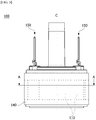
- FIG. 1 is a view illustrating a motor according to an embodiment.
- an x-direction represents an axial direction
- a y-direction represents a radial direction.
- the axial direction and the radial direction may be perpendicular to each other.
- the axial direction may be a longitudinal direction of a shaft 300.
- a motor 1 may include a stator 100 according to an embodiment, a rotor 200 disposed inside the stator 100, the shaft 300, and a housing 400.
- the inside may refer to a direction toward the center C based on the radial direction, and an outside may refer to a direction opposite to the inside.
- the motor 1 may include a bearing 10 rotatably supporting the shaft 300.
- the stator 100 and the rotor 200 induce an electrical interaction.
- the rotor 200 rotates, and the shaft 300 rotates in connection therewith.
- the shaft 300 may be connected to a clutch transmission to provide power.
- the shaft 300 may be connected to a dual-clutch transmission (DCT) to provide power.
- the dual-clutch transmission (DCT) may be provided with two sets of clutches, unlike a single-plate clutch transmission mounted on a manual transmission vehicle according to the related art.
- the dual-clutch transmission (DCT) is a system that implements first, third, and fifth gears with power transmitted through one clutch, and second, fourth, and sixth gears with power transmitted through the other one clutch.
- the dual-clutch transmission (DCT) may selectively receive the power of the shaft 300.
- the stator 100 may be disposed outside the rotor 200.
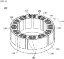
- FIG. 2 is a perspective view illustrating a stator according to an embodiment
- FIG. 3 is a side view illustrating a stator according to an embodiment
- FIG. 4 is a cross-sectional perspective view of the stator taken along line A-A of FIG. 3
- FIG. 5 is a perspective view illustrating a stator from which a molding portion is removed in the stator disposed in a motor according to an embodiment
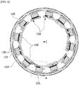
- FIG. 6 is a plan view illustrating a stator from which a molding portion is removed in the stator disposed in a motor according to an embodiment
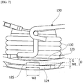
- FIG. 7 is an enlarged view of region A of FIG. 6 .
- the stator 100 may include a stator core 110, an insulator 120 disposed on the stator core 110, a coil 130 wound around the insulator 120, a molding portion 140 disposed to cover the stator core 110, the insulator 120, and the coil 130, and a terminal 150 electrically connected to an end portion of the coil 130.
- the insulator 120 may be primarily injection-molded on the stator core 110 by an injection method.
- the insulator 120 may surround a part of the stator core 110.
- the molding portion 140 may be secondarily injection-molded by an injection method.
- An insert injection method may be used as the injection method.
- the stator core 110 may include a yoke 111 having a cylindrical shape and a plurality of teeth 112 that are formed to protrude in the radial direction along the circumferential direction of the yoke 111 based on an imaginary line (axial direction) passing through the center C of the yoke 111.
- the plurality of teeth 112 may be disposed to face a magnet of the rotor 200.
- each of the teeth 112 may be disposed on the inner circumferential surface of the yoke 111 toward the center C.
- the teeth 112 may be formed in a T-shaped cross section when viewed from the axial direction, as shown in FIG. 4 .
- the teeth 112 may include an L-shaped tooth body and a shoe disposed at an end portion of the tooth body.
- the shoe may be formed to protrude from the end portion of the tooth body in the circumferential direction with respect to the center C, as shown in FIG. 4 .
- the stator core 110 may be formed by stacking a plurality of thin plate-shaped stator plates so that the plurality of teeth 112 may protrude in the radial direction.
- the stator plates may be formed of a plurality of silicon steel sheets having a thickness of 0.35 to 0.5 mm and formed into a predetermined shape.
- the stator core 110 may be formed by stacking the plurality of stator plates.
- the insulator 120 may be disposed to surround a region of the stator core 110 by an insert injection method.
- the insulator 120 allows the stator core 110 to be insulated from the coil 130. Specifically, the insulator 120 insulates each of the teeth 112 of the stator core 110 from the coil 130.
- the insulator 120 may be formed of a synthetic resin material.
- FIG. 8 is a view illustrating an insulator of a stator disposed in a motor according to an embodiment.
- the insulator 120 may include a first insulator 120a, a second insulator 120b, and a third insulator 120c. As shown in FIG. 8 , the second insulator 120b may be disposed between the first insulators 120a based on the circumferential direction. In addition, three first insulators 120a may be provided.
- the first insulator 120a, the second insulator 120b, and the third insulator 120c may be classified by whether a groove is formed in the upper side of an inner guide and by whether a protrusion is formed on a second outer guide.
- Each of the first insulator 120a, the second insulator 120b, and the third insulator 120c includes a body portion 121 around which the coil 130 is wound, an inner guide 122 protruding from the inside of the body portion 121, a first outer guide 123 protruding from the outside of the body portion 121, and a second outer guide 124 disposed to be spaced outward from the first outer guide 123 protruding from the outside of the body portion 121.
- the first outer guide 123 and the second outer guide 124 may be disposed to be spaced apart from each other by a predetermined separation distance D.
- the separation distance D may be 1.6 to 2.0 times an outer diameter of the coil 130.
- the outer diameter of the coil 130 may be referred to as a wire diameter or diameter of the coil 130.
- each of the first insulator 120a, the second insulator 120b, and the third insulator 120c may include a connection portion 126 that is disposed between the first outer guide 123 and the second outer guide 124 to connect the first outer guide 123 to the second outer guide 124.
- FIG. 9 is a side view showing a first insulator of a stator disposed in a motor according to an embodiment.
- the first insulator 120a may include a body portion 121, an inner guide 122 protruding from the inside of the body portion 121, a first outer guide 123 protruding from the outside of the body portion 121, a second outer guide 124 disposed to be spaced outward from the first outer guide 123 protruding from the outside of the body portion 121, a protrusion 125 protruding inward from the second outer guide, and a connection portion 126 connecting the first outer guide 123 and the second outer guide 124 to each other.
- the body portion 121 may be disposed to surround the teeth body of the teeth 112.
- the coil 130 may be wound around the body portion 121.
- a guide groove 121a for guiding the winding of the coil 130 may be formed at one side of the body portion 121.
- the inner guide 122 may be formed to extend from the inside of the body portion 121 in a direction perpendicular thereto. In this case, the inner guide 122 may be formed to protrude from the inside of the body portion 121 in the axial direction and the circumferential direction.
- the inner guide 122 may support the coil 130 wound around the body portion 121 to prevent the coil 130 from being separated in an inward direction.
- the first outer guide 123 may be formed to extend from the outside of the body portion 121 in a direction perpendicular thereto. In this case, the first outer guide 123 may be formed to protrude from the outside of the body portion 121 in the axial direction and the circumferential direction.
- the first outer guide 123 may support the coil 130 wound around the body portion 121 to prevent the coil 130 from being separated in an outward direction.
- the first outer guide 123 may be disposed on the top or bottom surface of the yoke 111. Thus, the first outer guide 123 may be disposed to overlap the yoke 311 in the axial direction.
- the second outer guide 124 may be disposed to be spaced apart from the first outer guide 123 by a predetermined separation distance D.
- the second outer guide 124 may be formed to extend from one side of the connection portion 126 in the radial direction in a direction perpendicular thereto.
- the second outer guide 124 may be formed to protrude from the outside of the connection portion 126 in the axial direction.
- a region of the coil 130 wound in the circumferential direction may be disposed between the first outer guide 123 and the second outer guide 124.
- the second outer guide 124 prevents the coil 130 from being exposed in the radial direction by the injection pressure generated when secondary injection for forming the molding portion 140 using a mold material is performed.
- the second outer guide 124 may be disposed on the top or bottom surface of the yoke 111.
- the second outer guide 124 may be disposed to overlap the yoke 311 in the axial direction.
- the protrusion 125 may prevent a part of the coil 130 disposed between the first outer guide 123 and the second outer guide 124 from being separated in the axial direction by the injection pressure.
- the protrusion 125 may be formed to protrude inward from the top of the second outer guide 124.
- the end portion of the protrusion 125 may be disposed such that a predetermined gap G may be formed between the end portion and the outer surface 123a of the first outer guide 123 based on the radial direction.
- the coil 130 may be inserted into the gap G between the first outer guide 123 and the second outer guide 124.
- the gap G may be slightly greater than or equal to the outer diameter of the coil 130.
- the outer surface 123a of the first outer guide 123 may be formed to have an inclined surface having a predetermined inclination angle with respect to the connection portion 126.
- the end portion of the protrusion 125 may be rounded.
- the top surface of the end portion of the protrusion 125 may be formed as a curved surface so that the coil 130 may be inserted between the first outer guide 123 and the second outer guide 124.
- the coil 130 may be easily inserted between the first outer guide 123 and the second outer guide 124 through the outer surface 123a of the first outer guide 123 formed to be inclined with the curved surface.
- a width W1 of the protrusion 125 in the radial direction may be 0.6 times or more of the outer diameter of the coil 130. Even in this case, the width W1 is formed in consideration of the gap G.
- a width W2 of the protrusion 125 in the circumferential direction may be twice or more of the outer diameter of the coil 130.
- the width W2 of the protrusion 125 in the circumferential direction is less than the width of the second outer guide 124 in the circumferential direction.
- the protrusion 125 may be formed to have a predetermined height H based on a top surface 126a of the connection portion 126.
- the height H may be three times or more of the outer diameter of the coil 130.
- the height H is less than the height of the second outer guide 124 in the axial direction.
- connection portion 126 may be disposed on the first outer guide 123 and the second outer guide 124 to connect the first outer guide 123 and the second outer guide 124.
- connection portion 126 may be disposed on the yoke 111.
- the coil 130 may be disposed on the connection portion 126.
- connection portion 126 allows the yoke 111 to be insulated from the coil 130.
- the second insulator 120b includes a body portion 121, an inner guide 122a protruding from the inside of the body portion 121, and a first outer guide 123 protruding from the outside of the body portion 121, a second outer guide 124 disposed to be spaced apart from the first outer guide 123 in the outward direction, and a connection portion 126 connecting the first outer guide 123 and the second outer guide 124.
- the same component as the first insulator 120a is denoted by the same reference numeral, and a detailed description thereof will be omitted.
- the inner guide 122a of the second insulator 120b may include a groove 122b formed for coupling with the terminal 150.
- the groove 122b may be formed in an end portion of the inner guide 122a. As shown in FIG. 8 , the groove 122b may be formed in an upper end of the inner guide 122a. Thus, one side of the terminal 150 may be coupled to the groove 122b.
- the third insulator 120c includes a body portion 121, an inner guide 122 protruding from the inside of the body portion 121, a first outer guide 123 protruding from the outside of the body portion 121, a second outer guide 124 disposed to be spaced outward from the first outer guide 123 protruding from the outside of the body portion 121, and a connection portion 126 connecting the first outer guide 123 and the second outer guide 124.
- the insulator 120 of the motor 1 may be formed by arranging the first insulator 120a, the second insulator 120b, and the third insulator 120c in the circumferential direction.
- the second insulator 120b is disposed between the first insulators 120a based on the circumferential direction in consideration of electrical connection between the end portion of the coil 130 and the terminal 150.
- the coil 130 may be wound around the body portion 121.
- the arrangement of the coil 130 may be guided by the guide groove 121a of the body portion 121.
- the end portion of the coil 130 disposed on the body portion 121 may be electrically connected to the terminal 150.
- the coil 130 may be wound and disposed between the first outer guide 123 and the second outer guide 124.
- the molding portion 140 may be disposed to cover the stator core 110, the insulator 120, and the coil 130.
- the molding portion 140 may be disposed between the coil 130 and the coil 130 wound around each of the body portions 121.
- the two coils 130 disposed to be spaced apart from each other may be insulated by the molding portion 140.
- the stator core 110 having a plurality of teeth 112 formed thereon may be disposed in a mold (not shown), and the insulator 120 may be formed through an insert injection method.
- the insulator 120 may be formed of any one of a resin, synthetic resin, rubber, and urethane.
- the coil 130 may be wound after the insulator 120 is formed in a state in which the stator core 110 is deployed.
- the coil 130 may be wound around the stator core 110 in which the insulator 120 is injection-molded.
- the coil 130 may be wound after the insulator 120 is formed in a state in which the stator core 110 is deployed. Then, one side and the other side of the deployable stator core 110 may be brought into contact with each other through a rolling process and then welded to form a cylindrical shape.
- a molding portion 140 may be injection-molded on the stator core 110 around which the coil 130 is wound after the rolling process is completed.
- the stator core 110 around which the coil 130 is wound may be disposed in a mold (not shown), and the molding portion 140 may be formed through an insert injection method.
- the molding portion 140 may be formed of any one of a resin, synthetic resin, rubber, and urethane.
- the insulator 120 may be primarily formed by injection, then, the coil 130 may be wound, and the molding portion 140 may be secondarily formed by an injection method.
- the coil 130 may be prevented from being exposed to the outside by the second outer guide 124 and the protrusion 125.
- the terminal 150 may be disposed to be electrically connected to one end of the coil 130. Thus, a current may be applied to the coil 130 through the terminal 150 partially exposed to the outside. Thus, as a current flows through the coil 130, a rotating magnetic field is formed between the stator 100 and the rotor 200, and thus, the rotor 200 rotates.
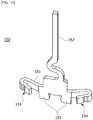
- FIG. 10 is a view illustrating a terminal of a stator disposed in a motor according to an embodiment.
- the terminal 150 includes a terminal body 151, a pin portion 152 protruding from the top surface of the terminal body 151 in the axial direction, and a projection portion 153 protruding from the bottom surface of the terminal body 151 in the axial direction, and a bent portion 154 formed by bending each of both sides of the terminal body 151.
- the projection portion 153 may be coupled to the groove 122b.
- the terminal 150 since the end portion of the coil 130 is disposed in the bent portion 154, the terminal 150 may be electrically connected to the coil 130.
- a part of the pin portion 152 may be exposed to the outside and electrically connected to an external power supply (not shown) that applies an external current.
- the rotor 200 may be disposed inside the stator 100.
- the rotor 200 may be configured by coupling a magnet (not shown) to a rotor core (not shown).
- the magnet may be inserted into a pocket provided in the rotor core.
- the rotor 200 may be formed by attaching the magnet to the outer peripheral surface of the rotor core.
- the rotor 200 may rotate in combination with the shaft 300.
- the shaft 300 may be coupled to the central portion of the rotor 200.
- a bearing 10 may be disposed on an outer peripheral surface of the shaft 300.
- the bearing 10 may be rotatably supported by the shaft 300.
- the housing 400 may form the outer shape of the motor 1 and determine the size of the motor 1.
- the housing 400 may accommodate the stator 100 and the rotor 200. That is, as shown in FIG. 1 , the stator 100 and the rotor 200 may be disposed inside the housing 400.
Landscapes
- Engineering & Computer Science (AREA)
- Power Engineering (AREA)
- Manufacturing & Machinery (AREA)
- Insulation, Fastening Of Motor, Generator Windings (AREA)
Abstract
Description
- The present invention relates to a stator and a motor including the same.
- A motor is a device that converts electrical energy into mechanical energy to obtain rotational force and is widely used in vehicles, home electronics, and industrial equipment.
- The motor may include a housing, a shaft, a stator disposed inside the housing, a rotor installed on an outer peripheral surface of the shaft, and the like. Here, the stator of the motor induces an electrical interaction with the rotor to induce the rotation of the rotor. The shaft also rotates according to the rotation of the rotor.
- In particular, the motor can be used in a device for ensuring the stability of steering of a vehicle. For example, the motor may be used in a vehicle motor such as an electronic power steering system (EPS).
- In addition, the motor can be used in a clutch actuator.
- A transmission of the vehicle is a transmission that is manually operated according to a user's clutch operation or automatically operated according to a speed by the transmission and includes a motor.
- Such motors can be disposed in environments exposed to fluids such as oil.
- Thus, in the case of the stator of the motor, the stator of the motor may be manufactured by an injection method using a material such as a mold for insulation of the coil.
- The stator may be formed by primary injection, by which an insulator is formed on a stator core, and by secondary injection by which a coil is wound around the insulator and then over-molding is performed.
- However, when the secondary injection is performed, the coil wound around the insulator may be exposed by injection molding pressure. Thus, since the exposed coil may be in contact with the housing, there is a possibility of a short circuit.
- Therefore, when the secondary injection is performed, a forming process is additionally performed to prevent exposure of the coil, but, in the case of the forming process, a production cost may increase.
- The present invention is directed to providing a stator that is capable of preventing exposure of a coil due to over-molding and a motor including the same.
- The technical problem to be achieved by the present invention is not limited to the technical problems as described above, and other technical problems not described herein will be clearly understood by those skilled in the art from the following description.
- One aspect of the present invention provides a stator including: a stator core including a yoke and a plurality of teeth protruding from an inner surface of the yoke; an insulator surrounding a part of the stator core; a coil wound around the insulator; and a molding portion disposed to cover the stator core, the insulator, and the coil, wherein the insulator includes a first insulator and a second insulator, the first insulator includes a body portion around which the coil is wound, an inner guide extending from an inside of the body portion in a direction perpendicular thereto, a first outer guide extending from an outside of the body portion in a direction perpendicular thereto, a second outer guide disposed to be spaced apart from the first outer guide in an outward direction, and a protrusion protruding inward from the second outer guide, an end portion of the protrusion is disposed such that a predetermined gap (G) is formed between the end portion and the first outer guide, and a part of the coil is disposed between the first outer guide and the second outer guide through the gap (G).
- A width (W1) of the protrusion in a radial direction may be 0.6 times or more of an outer diameter of the coil.
- A width (W2) of the protrusion in a circumferential direction may be twice or more of the outer diameter of the coil.
- The insulator may include a connection portion disposed between the first outer guide and the second outer guide, the connection portion may be disposed on the yoke, and a height (H) from the connection portion to the protrusion may be three times or more of the outer diameter of the coil.
- The stator may further include a terminal connected to an end portion of the coil, wherein the second insulator includes a body portion around which the coil is wound, a first outer guide extending from an outside of the body portion in a direction perpendicular thereto, a second outer guide disposed to be spaced apart from the first outer guide in an outward direction, and an inner guide extending from an inside of the body portion in a direction perpendicular thereto, and a groove to which one side of the terminal is coupled is formed in an upper end of the inner guide.
- The terminal may include a terminal body, a pin portion protruding from a top surface of the terminal body, a projection portion protruding from a bottom surface of the terminal body, and a bent portion formed by bending each of both sides of the terminal body, and the protrusion is coupled to the groove.
- The second insulator may be disposed between three first insulators based on a circumferential direction.
- The insulator may be disposed on the stator core by an injection method. The molding portion may be formed by an injection method in a state in which the coil is wound around the insulator.
- Another aspect of the present invention provides a motor including: a shaft; a rotor that rotates in combination with the shaft; and a stator disposed outside the rotor, wherein the stator includes a stator core, an insulator surrounding a part of the stator core, a coil wound around the insulator, and a molding portion disposed to cover the stator core, the insulator, and the coil, and the insulator includes a first insulator and a second insulator, and the first insulator includes a body portion around which the coil is wound, an inner guide extending from an inside of the body portion in a direction perpendicular thereto, a first outer guide extending from an outside of the body portion in a direction perpendicular thereto, a second outer guide disposed to be spaced apart from the first outer guide in an outward direction, and a protrusion protruding inward from the second outer guide, and an end portion of the protrusion is disposed such that a predetermined gap (G) is formed between the end portion and the first outer guide, and a part of the coil is disposed between the first outer guide and the second outer guide through the gap (G).
- After the insulator is primarily formed on the stator core by an injection method, the molding portion may be secondarily formed by an injection method in a state in which the coil is wound around the insulator.
- A region of the coil may be between the first outer guide and the second outer guide.
- In a stator and a motor including the same according to embodiments having the above-described configuration, since a second outer guide and a protrusion protruding inward from the second outer guide are used, a coil can be prevented from being exposed to the outside of a molding portion by injection molding pressure during over-molding.
- Various and beneficial advantages and effects of the embodiments are not limited to the above description and may be more easily understood in the process of describing specific examples of the embodiments.
-
-
FIG. 1 is a view illustrating a motor according to an embodiment. -
FIG. 2 is a perspective view illustrating a stator according to an embodiment. -
FIG. 3 is a side view illustrating a stator according to an embodiment. -
FIG. 4 is a cross-sectional perspective view of the stator taken along line A-A ofFIG. 3 . -
FIG. 5 is a perspective view illustrating a stator from which a molding portion is removed in the stator disposed in a motor according to an embodiment. -
FIG. 6 is a plan view illustrating a stator from which a molding portion is removed in the stator disposed in a motor according to an embodiment. -
FIG. 7 is an enlarged view of region A ofFIG. 6 . -
FIG. 8 is a view illustrating an insulator of a stator disposed in a motor according to an embodiment. -
FIG. 9 is a side view illustrating a first insulator of a stator disposed in a motor according to an embodiment. -
FIG. 10 is a view illustrating a terminal of a stator disposed in a motor according to an embodiment. - Hereinafter, exemplary embodiments of the present invention will be described in detail with reference to the accompanying drawings.
- However, the technical idea of the present invention is not limited to some embodiments described herein but can be implemented in various forms, and when the embodiments are within the scope of the technical idea of the present invention, one or more of components between the embodiments may be selectively combined and substituted.
- In addition, terms (including technical and scientific terms) used in the embodiments of the present invention may be interpreted in a sense that can be generally understood by those of ordinary skill in the art to which the present invention belongs, unless explicitly defined and described. The meaning of generally used terms, such as terms defined in a dictionary, may be interpreted in consideration of the meaning in the context of the related technology.
- In addition, terms used in the embodiments of the present invention are for describing the embodiments and are not intended to limit the present invention.
- In the present specification, the singular form may include the plural form unless specifically stated in the phrase, and when described as "at least one (or one or more) of A, B, and C", it may include one or more of all possible combinations with A, B, and C.
- In addition, terms such as first, second, A, B, (a), and (b) may be used in describing the components of the embodiment of the present invention.
- These terms are only for distinguishing the component from other components and are not limited to the nature, order, or order of the components by the term.
- Further, when a component is described as being "connected," "coupled," or "linked" to another component, the component is not only directly connected, coupled or linked to another component, but also the component may also include the case of being "connected," "coupled," or "linked" to another component with still another component disposed therebetween.
- In addition, when a component is described as being formed or disposed on the "top (upper) or bottom (lower)" of each component, the top (upper) or bottom (lower) includes the case where one or more other components are formed or disposed with still another component disposed therebetween as well as the case where two components are in direct contact with each other. In addition, when expressed as "top (upper) or bottom (lower)", the meaning of not only an upward direction but also a downward direction based on one component may be included.
- Hereinafter, embodiments will be described in detail with reference to the accompanying drawings, but the same reference numerals are assigned to identical or corresponding components regardless of the reference numerals, and redundant descriptions thereof will be omitted.
-
FIG. 1 is a view illustrating a motor according to an embodiment. InFIG. 1 , an x-direction represents an axial direction, and a y-direction represents a radial direction. The axial direction and the radial direction may be perpendicular to each other. Here, the axial direction may be a longitudinal direction of ashaft 300. - Referring to
FIG. 1 , amotor 1 according to the embodiment may include astator 100 according to an embodiment, arotor 200 disposed inside thestator 100, theshaft 300, and ahousing 400. Here, the inside may refer to a direction toward the center C based on the radial direction, and an outside may refer to a direction opposite to the inside. - Also, the
motor 1 may include abearing 10 rotatably supporting theshaft 300. - The
stator 100 and therotor 200 induce an electrical interaction. When an electrical interaction is induced, therotor 200 rotates, and theshaft 300 rotates in connection therewith. Theshaft 300 may be connected to a clutch transmission to provide power. Furthermore, theshaft 300 may be connected to a dual-clutch transmission (DCT) to provide power. Here, the dual-clutch transmission (DCT) may be provided with two sets of clutches, unlike a single-plate clutch transmission mounted on a manual transmission vehicle according to the related art. Thus, the dual-clutch transmission (DCT) is a system that implements first, third, and fifth gears with power transmitted through one clutch, and second, fourth, and sixth gears with power transmitted through the other one clutch. The dual-clutch transmission (DCT) may selectively receive the power of theshaft 300. - As illustrated in
FIG. 1 , thestator 100 may be disposed outside therotor 200. -
FIG. 2 is a perspective view illustrating a stator according to an embodiment,FIG. 3 is a side view illustrating a stator according to an embodiment,FIG. 4 is a cross-sectional perspective view of the stator taken along line A-A ofFIG. 3 ,FIG. 5 is a perspective view illustrating a stator from which a molding portion is removed in the stator disposed in a motor according to an embodiment,FIG. 6 is a plan view illustrating a stator from which a molding portion is removed in the stator disposed in a motor according to an embodiment, andFIG. 7 is an enlarged view of region A ofFIG. 6 . - Referring to
FIGS. 2 through 7 , thestator 100 may include astator core 110, aninsulator 120 disposed on thestator core 110, acoil 130 wound around theinsulator 120, amolding portion 140 disposed to cover thestator core 110, theinsulator 120, and thecoil 130, and a terminal 150 electrically connected to an end portion of thecoil 130. - Here, the
insulator 120 may be primarily injection-molded on thestator core 110 by an injection method. Thus, theinsulator 120 may surround a part of thestator core 110. In addition, in a state in which thecoil 130 is wound around theinsulator 120, themolding portion 140 may be secondarily injection-molded by an injection method. An insert injection method may be used as the injection method. - The
stator core 110 may include ayoke 111 having a cylindrical shape and a plurality ofteeth 112 that are formed to protrude in the radial direction along the circumferential direction of theyoke 111 based on an imaginary line (axial direction) passing through the center C of theyoke 111. The plurality ofteeth 112 may be disposed to face a magnet of therotor 200. - As shown in
FIG. 4 , each of theteeth 112 may be disposed on the inner circumferential surface of theyoke 111 toward the center C. - In addition, the
teeth 112 may be formed in a T-shaped cross section when viewed from the axial direction, as shown inFIG. 4 . - Thus, the
teeth 112 may include an L-shaped tooth body and a shoe disposed at an end portion of the tooth body. Here, the shoe may be formed to protrude from the end portion of the tooth body in the circumferential direction with respect to the center C, as shown inFIG. 4 . - Meanwhile, the
stator core 110 may be formed by stacking a plurality of thin plate-shaped stator plates so that the plurality ofteeth 112 may protrude in the radial direction. For example, the stator plates may be formed of a plurality of silicon steel sheets having a thickness of 0.35 to 0.5 mm and formed into a predetermined shape. In addition, thestator core 110 may be formed by stacking the plurality of stator plates. - The
insulator 120 may be disposed to surround a region of thestator core 110 by an insert injection method. - The
insulator 120 allows thestator core 110 to be insulated from thecoil 130. Specifically, theinsulator 120 insulates each of theteeth 112 of thestator core 110 from thecoil 130. Here, theinsulator 120 may be formed of a synthetic resin material. -
FIG. 8 is a view illustrating an insulator of a stator disposed in a motor according to an embodiment. - Referring to
FIG. 8 , theinsulator 120 may include afirst insulator 120a, asecond insulator 120b, and athird insulator 120c. As shown inFIG. 8 , thesecond insulator 120b may be disposed between thefirst insulators 120a based on the circumferential direction. In addition, threefirst insulators 120a may be provided. - Here, the
first insulator 120a, thesecond insulator 120b, and thethird insulator 120c may be classified by whether a groove is formed in the upper side of an inner guide and by whether a protrusion is formed on a second outer guide. - Each of the
first insulator 120a, thesecond insulator 120b, and thethird insulator 120c includes abody portion 121 around which thecoil 130 is wound, aninner guide 122 protruding from the inside of thebody portion 121, a firstouter guide 123 protruding from the outside of thebody portion 121, and a secondouter guide 124 disposed to be spaced outward from the firstouter guide 123 protruding from the outside of thebody portion 121. In this case, the firstouter guide 123 and the secondouter guide 124 may be disposed to be spaced apart from each other by a predetermined separation distance D. In addition, the separation distance D may be 1.6 to 2.0 times an outer diameter of thecoil 130. Here, the outer diameter of thecoil 130 may be referred to as a wire diameter or diameter of thecoil 130. - In addition, each of the
first insulator 120a, thesecond insulator 120b, and thethird insulator 120c may include aconnection portion 126 that is disposed between the firstouter guide 123 and the secondouter guide 124 to connect the firstouter guide 123 to the secondouter guide 124. -
FIG. 9 is a side view showing a first insulator of a stator disposed in a motor according to an embodiment. - Referring to
FIGS. 8 and9 , thefirst insulator 120a may include abody portion 121, aninner guide 122 protruding from the inside of thebody portion 121, a firstouter guide 123 protruding from the outside of thebody portion 121, a secondouter guide 124 disposed to be spaced outward from the firstouter guide 123 protruding from the outside of thebody portion 121, aprotrusion 125 protruding inward from the second outer guide, and aconnection portion 126 connecting the firstouter guide 123 and the secondouter guide 124 to each other. - The
body portion 121 may be disposed to surround the teeth body of theteeth 112. In addition, thecoil 130 may be wound around thebody portion 121. In this case, aguide groove 121a for guiding the winding of thecoil 130 may be formed at one side of thebody portion 121. - The
inner guide 122 may be formed to extend from the inside of thebody portion 121 in a direction perpendicular thereto. In this case, theinner guide 122 may be formed to protrude from the inside of thebody portion 121 in the axial direction and the circumferential direction. - The
inner guide 122 may support thecoil 130 wound around thebody portion 121 to prevent thecoil 130 from being separated in an inward direction. - The first
outer guide 123 may be formed to extend from the outside of thebody portion 121 in a direction perpendicular thereto. In this case, the firstouter guide 123 may be formed to protrude from the outside of thebody portion 121 in the axial direction and the circumferential direction. - The first
outer guide 123 may support thecoil 130 wound around thebody portion 121 to prevent thecoil 130 from being separated in an outward direction. - The first
outer guide 123 may be disposed on the top or bottom surface of theyoke 111. Thus, the firstouter guide 123 may be disposed to overlap the yoke 311 in the axial direction. - The second
outer guide 124 may be disposed to be spaced apart from the firstouter guide 123 by a predetermined separation distance D. Here, the secondouter guide 124 may be formed to extend from one side of theconnection portion 126 in the radial direction in a direction perpendicular thereto. For example, the secondouter guide 124 may be formed to protrude from the outside of theconnection portion 126 in the axial direction. - As shown in
FIGS. 6 and7 , a region of thecoil 130 wound in the circumferential direction may be disposed between the firstouter guide 123 and the secondouter guide 124. In addition, the secondouter guide 124 prevents thecoil 130 from being exposed in the radial direction by the injection pressure generated when secondary injection for forming themolding portion 140 using a mold material is performed. - Meanwhile, the second
outer guide 124 may be disposed on the top or bottom surface of theyoke 111. Thus, the secondouter guide 124 may be disposed to overlap the yoke 311 in the axial direction. - The
protrusion 125 may prevent a part of thecoil 130 disposed between the firstouter guide 123 and the secondouter guide 124 from being separated in the axial direction by the injection pressure. - Referring to
FIGS. 6 ,7 and9 , theprotrusion 125 may be formed to protrude inward from the top of the secondouter guide 124. In this case, the end portion of theprotrusion 125 may be disposed such that a predetermined gap G may be formed between the end portion and theouter surface 123a of the firstouter guide 123 based on the radial direction. Thus, thecoil 130 may be inserted into the gap G between the firstouter guide 123 and the secondouter guide 124. In this case, the gap G may be slightly greater than or equal to the outer diameter of thecoil 130. Here, theouter surface 123a of the firstouter guide 123 may be formed to have an inclined surface having a predetermined inclination angle with respect to theconnection portion 126. - Furthermore, the end portion of the
protrusion 125 may be rounded. For example, the top surface of the end portion of theprotrusion 125 may be formed as a curved surface so that thecoil 130 may be inserted between the firstouter guide 123 and the secondouter guide 124. Thus, thecoil 130 may be easily inserted between the firstouter guide 123 and the secondouter guide 124 through theouter surface 123a of the firstouter guide 123 formed to be inclined with the curved surface. - Referring to
FIGS. 7 and9 , a width W1 of theprotrusion 125 in the radial direction may be 0.6 times or more of the outer diameter of thecoil 130. Even in this case, the width W1 is formed in consideration of the gap G. - Referring to
FIG. 7 , a width W2 of theprotrusion 125 in the circumferential direction may be twice or more of the outer diameter of thecoil 130. In this case, the width W2 of theprotrusion 125 in the circumferential direction is less than the width of the secondouter guide 124 in the circumferential direction. Thus, cracks do not occur due to the force by which thecoil 130 is pushed in the axial direction by the injection pressure. - Referring to
FIGS. 7 and9 , theprotrusion 125 may be formed to have a predetermined height H based on atop surface 126a of theconnection portion 126. In this case, the height H may be three times or more of the outer diameter of thecoil 130. However, the height H is less than the height of the secondouter guide 124 in the axial direction. - The
connection portion 126 may be disposed on the firstouter guide 123 and the secondouter guide 124 to connect the firstouter guide 123 and the secondouter guide 124. - The
connection portion 126 may be disposed on theyoke 111. In addition, thecoil 130 may be disposed on theconnection portion 126. Thus, theconnection portion 126 allows theyoke 111 to be insulated from thecoil 130. - Referring to
FIG. 8 , thesecond insulator 120b includes abody portion 121, aninner guide 122a protruding from the inside of thebody portion 121, and a firstouter guide 123 protruding from the outside of thebody portion 121, a secondouter guide 124 disposed to be spaced apart from the firstouter guide 123 in the outward direction, and aconnection portion 126 connecting the firstouter guide 123 and the secondouter guide 124. - When comparing the
second insulator 120b with thefirst insulator 120a, in the case of thesecond insulator 120b, there is a difference in that theprotrusion 125 is removed and in the shape of theinner guide 122a. - In describing the
second insulator 120b and thefirst insulator 120a, the same component as thefirst insulator 120a is denoted by the same reference numeral, and a detailed description thereof will be omitted. - The
inner guide 122a of thesecond insulator 120b may include agroove 122b formed for coupling with the terminal 150. Thegroove 122b may be formed in an end portion of theinner guide 122a. As shown inFIG. 8 , thegroove 122b may be formed in an upper end of theinner guide 122a. Thus, one side of the terminal 150 may be coupled to thegroove 122b. - Referring to
FIG. 8 , thethird insulator 120c includes abody portion 121, aninner guide 122 protruding from the inside of thebody portion 121, a firstouter guide 123 protruding from the outside of thebody portion 121, a secondouter guide 124 disposed to be spaced outward from the firstouter guide 123 protruding from the outside of thebody portion 121, and aconnection portion 126 connecting the firstouter guide 123 and the secondouter guide 124. - When comparing the
third insulator 120c with thefirst insulator 120a, there is a difference in that thethird insulator 120c is formed by removing theprotrusion 125 of thefirst insulator 120a. - Thus, the
insulator 120 of themotor 1 may be formed by arranging thefirst insulator 120a, thesecond insulator 120b, and thethird insulator 120c in the circumferential direction. In this case, thesecond insulator 120b is disposed between thefirst insulators 120a based on the circumferential direction in consideration of electrical connection between the end portion of thecoil 130 and the terminal 150. - The
coil 130 may be wound around thebody portion 121. In this case, the arrangement of thecoil 130 may be guided by theguide groove 121a of thebody portion 121. In addition, the end portion of thecoil 130 disposed on thebody portion 121 may be electrically connected to the terminal 150. - Furthermore, the
coil 130 may be wound and disposed between the firstouter guide 123 and the secondouter guide 124. - The
molding portion 140 may be disposed to cover thestator core 110, theinsulator 120, and thecoil 130. In particular, themolding portion 140 may be disposed between thecoil 130 and thecoil 130 wound around each of thebody portions 121. Thus, the twocoils 130 disposed to be spaced apart from each other may be insulated by themolding portion 140. - In the injection process of the stator, the
stator core 110 having a plurality ofteeth 112 formed thereon may be disposed in a mold (not shown), and theinsulator 120 may be formed through an insert injection method. Here, theinsulator 120 may be formed of any one of a resin, synthetic resin, rubber, and urethane. - In particular, in the case of the
deployable stator core 110, thecoil 130 may be wound after theinsulator 120 is formed in a state in which thestator core 110 is deployed. - Also, the
coil 130 may be wound around thestator core 110 in which theinsulator 120 is injection-molded. - In particular, in the case of a
deployable stator core 110, thecoil 130 may be wound after theinsulator 120 is formed in a state in which thestator core 110 is deployed. Then, one side and the other side of thedeployable stator core 110 may be brought into contact with each other through a rolling process and then welded to form a cylindrical shape. - In addition, a
molding portion 140 may be injection-molded on thestator core 110 around which thecoil 130 is wound after the rolling process is completed. For example, thestator core 110 around which thecoil 130 is wound may be disposed in a mold (not shown), and themolding portion 140 may be formed through an insert injection method. Here, themolding portion 140 may be formed of any one of a resin, synthetic resin, rubber, and urethane. - That is, in the
stator 100, theinsulator 120 may be primarily formed by injection, then, thecoil 130 may be wound, and themolding portion 140 may be secondarily formed by an injection method. - In this case, during injection molding of the
molding portion 140, even when an injection pressure is applied to thecoil 130, thecoil 130 may be prevented from being exposed to the outside by the secondouter guide 124 and theprotrusion 125. - The terminal 150 may be disposed to be electrically connected to one end of the
coil 130. Thus, a current may be applied to thecoil 130 through the terminal 150 partially exposed to the outside. Thus, as a current flows through thecoil 130, a rotating magnetic field is formed between thestator 100 and therotor 200, and thus, therotor 200 rotates. -
FIG. 10 is a view illustrating a terminal of a stator disposed in a motor according to an embodiment. - Referring to
FIG. 10 , the terminal 150 includes aterminal body 151, apin portion 152 protruding from the top surface of theterminal body 151 in the axial direction, and aprojection portion 153 protruding from the bottom surface of theterminal body 151 in the axial direction, and abent portion 154 formed by bending each of both sides of theterminal body 151. In addition, theprojection portion 153 may be coupled to thegroove 122b. Also, since the end portion of thecoil 130 is disposed in thebent portion 154, the terminal 150 may be electrically connected to thecoil 130. In addition, a part of thepin portion 152 may be exposed to the outside and electrically connected to an external power supply (not shown) that applies an external current. - The
rotor 200 may be disposed inside thestator 100. - The
rotor 200 may be configured by coupling a magnet (not shown) to a rotor core (not shown). For example, the magnet may be inserted into a pocket provided in the rotor core. - Alternatively, the
rotor 200 may be formed by attaching the magnet to the outer peripheral surface of the rotor core. - The
rotor 200 may rotate in combination with theshaft 300. For example, theshaft 300 may be coupled to the central portion of therotor 200. - In addition, a
bearing 10 may be disposed on an outer peripheral surface of theshaft 300. Thus, the bearing 10 may be rotatably supported by theshaft 300. - The
housing 400 may form the outer shape of themotor 1 and determine the size of themotor 1. - In addition, the
housing 400 may accommodate thestator 100 and therotor 200. That is, as shown inFIG. 1 , thestator 100 and therotor 200 may be disposed inside thehousing 400. - While the present invention has been shown and described with reference to the exemplary embodiments thereof, it will be understood by those skilled in the art that various changes in form and details may be made therein without departing from the spirit and scope of the invention as defined by the scope of the appended claims.
- 1: motor, 100: stator, 110: stator core, 111: yoke, 112: tooth, 120: insulator, 121: body portion, 122: inner guide, 122b: groove, 123: first outer guide, 124: second outer guide, 125: protrusion, 130: coil, 140: molding portion, 150: terminal, 200: rotor, 300: shaft, 400: housing
Claims (11)
- A stator comprising:a stator core comprising a yoke and a plurality of teeth protruding from an inner surface of the yoke;an insulator surrounding a part of the stator core;a coil wound around the insulator; anda molding portion disposed to cover the stator core, the insulator, and the coil,wherein the insulator comprises a first insulator and a second insulator,the first insulator comprises:a body portion around which the coil is wound;an inner guide extending from an inside of the body portion in a direction perpendicular thereto;a first outer guide extending from an outside of the body portion in a direction perpendicular thereto;a second outer guide disposed to be spaced apart from the first outer guide in an outward direction; anda protrusion protruding inward from the second outer guide,an end portion of the protrusion is disposed such that a predetermined gap (G) is formed between the end portion and the first outer guide, anda part of the coil is disposed between the first outer guide and the second outer guide through the gap (G).
- The stator of claim 1, wherein a width (W1) of the protrusion in a radial direction is 0.6 times or more of an outer diameter of the coil.
- The stator of claim 2, wherein a width (W2) of the protrusion in a circumferential direction is twice or more of the outer diameter of the coil.
- The stator of claim 3, wherein the insulator comprises a connection portion disposed between the first outer guide and the second outer guide,
wherein the connection portion is disposed on the yoke, and
a height (H) from the connection portion to the protrusion is three times or more of the outer diameter of the coil. - The stator of claim 1, further comprising a terminal connected to an end portion of the coil,
wherein the second insulator comprises:a body portion around which the coil is wound;a first outer guide extending from an outside of the body portion in a direction perpendicular thereto;a second outer guide disposed to be spaced apart from the first outer guide in an outward direction; andan inner guide extending from an inside of the body portion in a direction perpendicular thereto, anda groove to which one side of the terminal is coupled is formed in an upper end of the inner guide. - The stator of claim 5, wherein the terminal comprises:a terminal body;a pin portion protruding from a top surface of the terminal body;a projection portion protruding from a bottom surface of the terminal body; anda bent portion formed by bending each of both sides of the terminal body, andthe protrusion is coupled to the groove.
- The stator of claim 1, wherein the second insulator is disposed between three first insulators based on a circumferential direction.
- The stator of claim 1, wherein the insulator is disposed on the stator core by an injection method.
- The stator of claim 8, wherein the molding portion is formed by an injection method in a state in which the coil is wound around the insulator.
- A motor comprising:a shaft;a rotor that rotates in combination with the shaft; anda stator disposed outside the rotor,wherein the stator comprises:a stator core;an insulator surrounding a part of the stator core;a coil wound around the insulator; anda molding portion disposed to cover the stator core, the insulator, and the coil, andthe insulator comprises a first insulator and a second insulator, andthe first insulator comprises:a body portion around which the coil is wound;an inner guide extending from an inside of the body portion in a direction perpendicular thereto;a first outer guide extending from an outside of the body portion in a direction perpendicular thereto;a second outer guide disposed to be spaced apart from the first outer guide in an outward direction; anda protrusion protruding inward from the second outer guide, andan end portion of the protrusion is disposed such that a predetermined gap (G) is formed between the end portion and the first outer guide, anda part of the coil is disposed between the first outer guide and the second outer guide through the gap (G).
- The motor of claim 10, wherein, after the insulator is primarily formed on the stator core by an injection method, the molding portion is secondarily formed by an injection method in a state in which the coil is wound around the insulator.
Applications Claiming Priority (2)
| Application Number | Priority Date | Filing Date | Title |
|---|---|---|---|
| KR1020180097600A KR102608163B1 (en) | 2018-08-21 | 2018-08-21 | Stator and Motor having the same |
| PCT/KR2019/008337 WO2020040424A1 (en) | 2018-08-21 | 2019-07-08 | Stator and motor comprising same |
Publications (2)
| Publication Number | Publication Date |
|---|---|
| EP3843243A1 true EP3843243A1 (en) | 2021-06-30 |
| EP3843243A4 EP3843243A4 (en) | 2021-10-20 |
Family
ID=69593298
Family Applications (1)
| Application Number | Title | Priority Date | Filing Date |
|---|---|---|---|
| EP19852601.4A Pending EP3843243A4 (en) | 2018-08-21 | 2019-07-08 | STATOR AND MOTOR INCLUDING THIS |
Country Status (6)
| Country | Link |
|---|---|
| US (2) | US11955840B2 (en) |
| EP (1) | EP3843243A4 (en) |
| JP (2) | JP7374989B2 (en) |
| KR (2) | KR102608163B1 (en) |
| CN (3) | CN112585841B (en) |
| WO (1) | WO2020040424A1 (en) |
Families Citing this family (5)
| Publication number | Priority date | Publication date | Assignee | Title |
|---|---|---|---|---|
| JP7268508B2 (en) * | 2019-07-09 | 2023-05-08 | 株式会社デンソー | Coil module and power converter |
| CN113572279A (en) * | 2020-04-29 | 2021-10-29 | 博世电动工具(中国)有限公司 | Motor stator module, motor and electric tool |
| KR102883727B1 (en) * | 2020-06-11 | 2025-11-11 | 엘지이노텍 주식회사 | Motor and a coil winding apparatus for preparing it |
| JP7562404B2 (en) * | 2020-12-25 | 2024-10-07 | ニデックインスツルメンツ株式会社 | Motors and pumps |
| FR3155379A1 (en) * | 2023-11-10 | 2025-05-16 | Safran Electronics & Defense | Annular stator of an electric machine and associated electric machine |
Family Cites Families (31)
| Publication number | Priority date | Publication date | Assignee | Title |
|---|---|---|---|---|
| JPS58201565A (en) * | 1982-05-18 | 1983-11-24 | Matsushita Electric Ind Co Ltd | Stator for rotary electric machine |
| JP3980402B2 (en) * | 2002-05-13 | 2007-09-26 | 本田技研工業株式会社 | Rotating electric machine |
| JP4619098B2 (en) * | 2004-11-17 | 2011-01-26 | トヨタ自動車株式会社 | Insulating member for stator and rotating machine having the same |
| JP2008167604A (en) * | 2006-12-28 | 2008-07-17 | Ichinomiya Denki:Kk | Stator of inner rotor type molded brushless motor |
| KR100883599B1 (en) * | 2007-02-26 | 2009-02-13 | 엘지전자 주식회사 | motor |
| JP5148260B2 (en) * | 2007-12-21 | 2013-02-20 | 三菱電機株式会社 | Stator for rotating electrical machine |
| JP5453881B2 (en) * | 2009-03-31 | 2014-03-26 | 日本電産株式会社 | motor |
| JP5389559B2 (en) * | 2009-07-23 | 2014-01-15 | 愛三工業株式会社 | Rotating motor stator and fuel pump |
| KR20110077819A (en) * | 2009-12-30 | 2011-07-07 | 계양전기 주식회사 | Stator insulator of brushless motor |
| JP5740930B2 (en) | 2010-03-03 | 2015-07-01 | 日本電産株式会社 | Stator and motor |
| JP2012075213A (en) * | 2010-09-28 | 2012-04-12 | Nidec Sankyo Corp | Stator |
| KR101848922B1 (en) * | 2011-09-21 | 2018-04-13 | 엘지이노텍 주식회사 | Terminal connection structure for Motor |
| JP5627819B2 (en) * | 2012-04-18 | 2014-11-19 | 三菱電機株式会社 | Stator, motor, blower, and stator manufacturing method |
| DE102012020329A1 (en) * | 2012-10-17 | 2014-04-17 | Sew-Eurodrive Gmbh & Co Kg | Electromotor has winding wire portion that is clipped into holding portion, in positively locking manner, for receiving winding wire whose end portions are connected together in accordance with connections of windings of stator |
| JP6175708B2 (en) * | 2013-02-18 | 2017-08-09 | 日本電産テクノモータ株式会社 | motor |
| JP6221034B2 (en) * | 2013-03-29 | 2017-11-01 | 日本電産株式会社 | Motor and motor manufacturing method |
| JP5738385B2 (en) * | 2013-11-18 | 2015-06-24 | 三菱電機株式会社 | Stator and rotating electric machine equipped with the stator |
| JP2015133808A (en) * | 2014-01-10 | 2015-07-23 | アスモ株式会社 | Insulator and stator |
| CN204216691U (en) | 2014-10-29 | 2015-03-18 | 日本电产高科电机株式会社 | Motor and comprise the electric equipment of this motor |
| JP6462468B2 (en) * | 2015-04-15 | 2019-01-30 | 株式会社ミツバ | Electric motor and method for manufacturing electric motor |
| KR102345928B1 (en) * | 2015-05-27 | 2022-01-03 | 엘지이노텍 주식회사 | Connector assembly and Motor using the same |
| JP6301899B2 (en) * | 2015-12-02 | 2018-03-28 | ミネベアミツミ株式会社 | Motor stator and inner rotor type motor provided with the stator |
| KR102516497B1 (en) * | 2016-02-03 | 2023-04-03 | 삼성전자주식회사 | Motor |
| JP6647908B2 (en) * | 2016-02-18 | 2020-02-14 | 日本航空電子工業株式会社 | Resolver stator |
| US10644561B2 (en) * | 2016-09-30 | 2020-05-05 | Minebea Mitsumi, Inc. | Stator structure and resolver |
| JP6597571B2 (en) * | 2016-11-28 | 2019-10-30 | トヨタ自動車株式会社 | Stator |
| KR102633270B1 (en) * | 2016-12-27 | 2024-02-05 | 엘지이노텍 주식회사 | Stator and Motor having the same |
| US11095171B2 (en) * | 2017-02-13 | 2021-08-17 | Lg Innotek Co., Ltd. | Stator and motor comprising same |
| CN110462986B (en) * | 2017-03-31 | 2021-08-31 | 日本电产株式会社 | motor |
| CN110521090B (en) * | 2017-03-31 | 2021-08-31 | 日本电产株式会社 | motor |
| DE102017209931A1 (en) * | 2017-06-13 | 2018-12-13 | Robert Bosch Gmbh | Electric machine, stator for an electric machine, and method of making such an electric machine |
-
2018
- 2018-08-21 KR KR1020180097600A patent/KR102608163B1/en active Active
-
2019
- 2019-07-08 EP EP19852601.4A patent/EP3843243A4/en active Pending
- 2019-07-08 CN CN201980054779.6A patent/CN112585841B/en active Active
- 2019-07-08 CN CN202310715039.0A patent/CN116914970A/en active Pending
- 2019-07-08 CN CN202310713287.1A patent/CN116914969A/en active Pending
- 2019-07-08 JP JP2021505988A patent/JP7374989B2/en active Active
- 2019-07-08 US US17/264,155 patent/US11955840B2/en active Active
- 2019-07-08 WO PCT/KR2019/008337 patent/WO2020040424A1/en not_active Ceased
-
2023
- 2023-10-20 KR KR1020230141291A patent/KR102696360B1/en active Active
- 2023-10-25 JP JP2023183373A patent/JP7648709B2/en active Active
-
2024
- 2024-03-06 US US18/596,781 patent/US20240213822A1/en active Pending
Also Published As
| Publication number | Publication date |
|---|---|
| CN112585841B (en) | 2023-06-23 |
| WO2020040424A1 (en) | 2020-02-27 |
| JP2021534709A (en) | 2021-12-09 |
| KR20230149798A (en) | 2023-10-27 |
| US11955840B2 (en) | 2024-04-09 |
| JP7648709B2 (en) | 2025-03-18 |
| CN116914969A (en) | 2023-10-20 |
| KR102608163B1 (en) | 2023-11-30 |
| JP2023182841A (en) | 2023-12-26 |
| JP7374989B2 (en) | 2023-11-07 |
| US20240213822A1 (en) | 2024-06-27 |
| CN116914970A (en) | 2023-10-20 |
| KR102696360B1 (en) | 2024-08-19 |
| EP3843243A4 (en) | 2021-10-20 |
| US20210234413A1 (en) | 2021-07-29 |
| CN112585841A (en) | 2021-03-30 |
| KR20200021799A (en) | 2020-03-02 |
Similar Documents
| Publication | Publication Date | Title |
|---|---|---|
| US20240213822A1 (en) | Stator and motor comprising same | |
| JP6935412B2 (en) | Busbar assembly, motor including this | |
| US11496012B2 (en) | Stator and motor including same | |
| US20090152975A1 (en) | Central electricity distribution member for rotary electric machine | |
| JP2007325482A (en) | Brushless motor | |
| US20110241474A1 (en) | Armature and motor | |
| US11942849B2 (en) | Motor | |
| US11909287B2 (en) | Insulator and motor comprising same | |
| US12101006B2 (en) | Motor, and method for manufacturing stator provided in motor | |
| KR20190013045A (en) | Motor | |
| CN112236925B (en) | Stator of rotating electrical machine and rotating electrical machine | |
| JP2010141965A (en) | Stator, rotary electric machine, method of manufacturing the stator, and method of manufacturing the rotary electric machine | |
| CN112673547A (en) | Motor | |
| CN114930692B (en) | motor | |
| CN104518577A (en) | Electric motor with a segmented stator | |
| CN112689943B (en) | Motor | |
| US20220376579A1 (en) | Motor | |
| KR20230083621A (en) | Motor | |
| KR20210042781A (en) | Motor | |
| JP2009240000A (en) | Insulator for electric motor | |
| KR20200021371A (en) | Motor | |
| KR20220082317A (en) | Motor | |
| JP2009065800A (en) | Stator midpoint connection structure |
Legal Events
| Date | Code | Title | Description |
|---|---|---|---|
| STAA | Information on the status of an ep patent application or granted ep patent |
Free format text: STATUS: THE INTERNATIONAL PUBLICATION HAS BEEN MADE |
|
| PUAI | Public reference made under article 153(3) epc to a published international application that has entered the european phase |
Free format text: ORIGINAL CODE: 0009012 |
|
| STAA | Information on the status of an ep patent application or granted ep patent |
Free format text: STATUS: REQUEST FOR EXAMINATION WAS MADE |
|
| 17P | Request for examination filed |
Effective date: 20210318 |
|
| AK | Designated contracting states |
Kind code of ref document: A1 Designated state(s): AL AT BE BG CH CY CZ DE DK EE ES FI FR GB GR HR HU IE IS IT LI LT LU LV MC MK MT NL NO PL PT RO RS SE SI SK SM TR |
|
| REG | Reference to a national code |
Ref country code: DE Ref legal event code: R079 Free format text: PREVIOUS MAIN CLASS: H02K0001040000 Ipc: H02K0003520000 |
|
| A4 | Supplementary search report drawn up and despatched |
Effective date: 20210921 |
|
| RIC1 | Information provided on ipc code assigned before grant |
Ipc: H02K 3/32 20060101ALI20210915BHEP Ipc: H02K 15/12 20060101ALI20210915BHEP Ipc: H02K 3/52 20060101AFI20210915BHEP |
|
| DAV | Request for validation of the european patent (deleted) | ||
| DAX | Request for extension of the european patent (deleted) | ||
| STAA | Information on the status of an ep patent application or granted ep patent |
Free format text: STATUS: EXAMINATION IS IN PROGRESS |
|
| 17Q | First examination report despatched |
Effective date: 20231116 |