EP3843078A1 - Method of controlling display device, and display device - Google Patents
Method of controlling display device, and display device Download PDFInfo
- Publication number
- EP3843078A1 EP3843078A1 EP20216912.4A EP20216912A EP3843078A1 EP 3843078 A1 EP3843078 A1 EP 3843078A1 EP 20216912 A EP20216912 A EP 20216912A EP 3843078 A1 EP3843078 A1 EP 3843078A1
- Authority
- EP
- European Patent Office
- Prior art keywords
- image
- luminance value
- section
- luminance
- pixels
- Prior art date
- Legal status (The legal status is an assumption and is not a legal conclusion. Google has not performed a legal analysis and makes no representation as to the accuracy of the status listed.)
- Pending
Links
Images






Classifications
-
- H—ELECTRICITY
- H04—ELECTRIC COMMUNICATION TECHNIQUE
- H04N—PICTORIAL COMMUNICATION, e.g. TELEVISION
- H04N9/00—Details of colour television systems
- H04N9/12—Picture reproducers
- H04N9/31—Projection devices for colour picture display, e.g. using electronic spatial light modulators [ESLM]
- H04N9/3179—Video signal processing therefor
-
- G—PHYSICS
- G09—EDUCATION; CRYPTOGRAPHY; DISPLAY; ADVERTISING; SEALS
- G09G—ARRANGEMENTS OR CIRCUITS FOR CONTROL OF INDICATING DEVICES USING STATIC MEANS TO PRESENT VARIABLE INFORMATION
- G09G5/00—Control arrangements or circuits for visual indicators common to cathode-ray tube indicators and other visual indicators
-
- G—PHYSICS
- G09—EDUCATION; CRYPTOGRAPHY; DISPLAY; ADVERTISING; SEALS
- G09G—ARRANGEMENTS OR CIRCUITS FOR CONTROL OF INDICATING DEVICES USING STATIC MEANS TO PRESENT VARIABLE INFORMATION
- G09G3/00—Control arrangements or circuits, of interest only in connection with visual indicators other than cathode-ray tubes
- G09G3/20—Control arrangements or circuits, of interest only in connection with visual indicators other than cathode-ray tubes for presentation of an assembly of a number of characters, e.g. a page, by composing the assembly by combination of individual elements arranged in a matrix no fixed position being assigned to or needed to be assigned to the individual characters or partial characters
- G09G3/34—Control arrangements or circuits, of interest only in connection with visual indicators other than cathode-ray tubes for presentation of an assembly of a number of characters, e.g. a page, by composing the assembly by combination of individual elements arranged in a matrix no fixed position being assigned to or needed to be assigned to the individual characters or partial characters by control of light from an independent source
- G09G3/36—Control arrangements or circuits, of interest only in connection with visual indicators other than cathode-ray tubes for presentation of an assembly of a number of characters, e.g. a page, by composing the assembly by combination of individual elements arranged in a matrix no fixed position being assigned to or needed to be assigned to the individual characters or partial characters by control of light from an independent source using liquid crystals
-
- G—PHYSICS
- G09—EDUCATION; CRYPTOGRAPHY; DISPLAY; ADVERTISING; SEALS
- G09G—ARRANGEMENTS OR CIRCUITS FOR CONTROL OF INDICATING DEVICES USING STATIC MEANS TO PRESENT VARIABLE INFORMATION
- G09G5/00—Control arrangements or circuits for visual indicators common to cathode-ray tube indicators and other visual indicators
- G09G5/02—Control arrangements or circuits for visual indicators common to cathode-ray tube indicators and other visual indicators characterised by the way in which colour is displayed
- G09G5/026—Control of mixing and/or overlay of colours in general
-
- G—PHYSICS
- G09—EDUCATION; CRYPTOGRAPHY; DISPLAY; ADVERTISING; SEALS
- G09G—ARRANGEMENTS OR CIRCUITS FOR CONTROL OF INDICATING DEVICES USING STATIC MEANS TO PRESENT VARIABLE INFORMATION
- G09G5/00—Control arrangements or circuits for visual indicators common to cathode-ray tube indicators and other visual indicators
- G09G5/36—Control arrangements or circuits for visual indicators common to cathode-ray tube indicators and other visual indicators characterised by the display of a graphic pattern, e.g. using an all-points-addressable [APA] memory
- G09G5/37—Details of the operation on graphic patterns
- G09G5/377—Details of the operation on graphic patterns for mixing or overlaying two or more graphic patterns
-
- H—ELECTRICITY
- H04—ELECTRIC COMMUNICATION TECHNIQUE
- H04N—PICTORIAL COMMUNICATION, e.g. TELEVISION
- H04N5/00—Details of television systems
- H04N5/222—Studio circuitry; Studio devices; Studio equipment
- H04N5/262—Studio circuits, e.g. for mixing, switching-over, change of character of image, other special effects ; Cameras specially adapted for the electronic generation of special effects
- H04N5/265—Mixing
-
- G—PHYSICS
- G09—EDUCATION; CRYPTOGRAPHY; DISPLAY; ADVERTISING; SEALS
- G09G—ARRANGEMENTS OR CIRCUITS FOR CONTROL OF INDICATING DEVICES USING STATIC MEANS TO PRESENT VARIABLE INFORMATION
- G09G2340/00—Aspects of display data processing
- G09G2340/12—Overlay of images, i.e. displayed pixel being the result of switching between the corresponding input pixels
-
- H—ELECTRICITY
- H04—ELECTRIC COMMUNICATION TECHNIQUE
- H04N—PICTORIAL COMMUNICATION, e.g. TELEVISION
- H04N9/00—Details of colour television systems
- H04N9/12—Picture reproducers
- H04N9/31—Projection devices for colour picture display, e.g. using electronic spatial light modulators [ESLM]
- H04N9/3102—Projection devices for colour picture display, e.g. using electronic spatial light modulators [ESLM] using two-dimensional electronic spatial light modulators
- H04N9/3105—Projection devices for colour picture display, e.g. using electronic spatial light modulators [ESLM] using two-dimensional electronic spatial light modulators for displaying all colours simultaneously, e.g. by using two or more electronic spatial light modulators
-
- H—ELECTRICITY
- H04—ELECTRIC COMMUNICATION TECHNIQUE
- H04N—PICTORIAL COMMUNICATION, e.g. TELEVISION
- H04N9/00—Details of colour television systems
- H04N9/12—Picture reproducers
- H04N9/31—Projection devices for colour picture display, e.g. using electronic spatial light modulators [ESLM]
- H04N9/3102—Projection devices for colour picture display, e.g. using electronic spatial light modulators [ESLM] using two-dimensional electronic spatial light modulators
- H04N9/312—Driving therefor
Definitions
- the present disclosure relates to a method of controlling a display device and a display device.
- the projector described in Document 1 has an image processing section for combining a first image based on first image information and a second image generated by converting luminance information of second image information having the luminance information into transmittance with each other based on the transmittance to thereby generate a third image, and an image forming section for displaying the third image.
- the luminance values of the pixels constituting an original image of the mask image include an intermediate gray level
- the luminance value of the intermediate gray level is converted into the transmittance of the intermediate gray level, and therefore, there is a possibility that the mask image desired by the user fails to be generated.
- An aspect for solving the problem described above is directed to a method of controlling a display device including a distributing step of distributing each of luminance values of a plurality of pixels constituting an original image into a first luminance value, a second luminance value lower than the first luminance value, and a third luminance value lower than the second luminance value, a first replacing step of replacing the luminance values of the pixels corresponding to the second luminance value with the third luminance value in the original image to generate a first image, a second replacing step of replacing the luminance values of the pixels corresponding to the second luminance value with the first luminance value in the original image to generate a second image, and a generating step of converting the luminance values of the pixels into transmittances in each of the first image and the second image to generate mask images.
- the method of controlling a display device described above may further include a third replacing step of replacing the luminance values of the pixels corresponding to the second luminance value with the third luminance value, and replacing the luminance values of the pixels corresponding to the third luminance value with the second luminance value in the original image to generate a third image, and a fourth replacing step of replacing the luminance values of the pixels corresponding to the second luminance value with the first luminance value, and replacing the luminance values of the pixels corresponding to the first luminance value with the second luminance value in the original image to generate a fourth image, wherein in the generating step, the luminance values of the pixels may be converted into transmittances in each of the third image and the fourth image to generate mask images.
- the method of controlling a display device described above may further include a fifth replacing step of replacing the luminance values of the pixels corresponding to the third luminance value with the first luminance value, and replacing the luminance values of the pixels corresponding to the first luminance value with the third luminance value in the first image to generate a fifth image, and a sixth replacing step of replacing the luminance values of the pixels corresponding to the third luminance value with the first luminance value, and replacing the luminance values of the pixels corresponding to the first luminance value with the third luminance value in the second image to generate a sixth image, wherein in the generating step, the luminance values of the pixels may be converted into transmittances in each of the fifth image and the sixth image to generate mask images.
- the method of controlling a display device described above may further include a seventh replacing step of replacing the luminance values of the pixels corresponding to the third luminance value with the first luminance value, and replacing the luminance values of the pixels corresponding to the first luminance value with the third luminance value in the third image to generate a seventh image, and an eighth replacing step of replacing the luminance values of the pixels corresponding to the third luminance value with the first luminance value, and replacing the luminance values of the pixels corresponding to the first luminance value with the third luminance value in the fourth image to generate an eighth image, wherein in the generating step, the luminance values of the pixels may be converted into transmittances in each of the seventh image and the eighth image to generate mask images.
- the first luminance value may represent a maximum luminance value
- the third luminance value may represent a minimum luminance value
- a display device including a distribution section configured to distribute each of luminance values of a plurality of pixels constituting an original image into a first luminance value, a second luminance value lower than the first luminance value, and a third luminance value lower than the second luminance value, a first replacement section configured to replace the luminance values of the pixels corresponding to the second luminance value with the third luminance value in the original image to generate a first image, a second replacement section configured to replace the luminance values of the pixels corresponding to the second luminance value with the first luminance value in the original image to generate a second image, and a generation section configured to convert the luminance values of the pixels into transmittances in each of the first image and the second image to generate mask images.
- FIG. 1 is a diagram showing an example of a configuration of a projector 1.
- the projector 1 is a display device which projects image light to a screen SC to thereby display a projection image PP on the screen SC by means of projection. It is also possible for the projector 1 to project either of a still image and a video picture, namely a moving image, as the projection image PP, and in the following description, there is used the description of "video" or "image.” Since the projector 1 updates the projection image PP at a preset frame rate with an image forming section 20 even when projecting a still image, there is no difference in the actual action between a still image and a video picture.
- the screen SC can be a curtain-like screen to be installed on a wall surface, a ceiling surface, or a floor surface in a room of a building, but it is possible to use the wall surface as the screen SC. Further, it is also possible to utilize a plane of an installation such as a whiteboard or furniture as the screen SC. Further, the screen SC is not limited to a plane, but can also be a curved surface or a surface having asperity.
- the projector 1 can use video data stored in a memory 10B described later as a video source of the projection image PP. Further, the video source of the projector 1 can be selected from a video signal input to the projector 1 from the video supply device 2, video data input to the projector 1 from a data output device 3, video data stored in a storage medium 4, and so on.
- the video supply device 2 is coupled to the projector 1 via a cable or a wireless communication line, and outputs an analog video signal or a digital video signal to the projector 1.
- the analog video signal is, for example, an analog video signal transmitted via a D-Sub connector or a D-terminal, or a composite video signal.
- the digital video signal is, for example, a signal transmitted via a variety of digital interfaces.
- HDMI registered trademark
- DVI DisplayPort
- WirelessHD registered trademark
- the video supply device 2 is formed of, for example, a video reproduction device such as a DVD (Digital Versatile Disc) player, a broadcast reception device such as a digital television tuner, a video game machine, or a personal computer. Further, the video supply device 2 can be formed of a communication device or the like for communicating with a personal computer and so on to receive the video data.
- a video reproduction device such as a DVD (Digital Versatile Disc) player
- a broadcast reception device such as a digital television tuner, a video game machine, or a personal computer.
- the video supply device 2 can be formed of a communication device or the like for communicating with a personal computer and so on to receive the video data.
- the data output device 3 is a device for outputting digital data of a video picture to the projector 1, and outputs a file encoded in, for example, the MPEG format to the projector 1. It is sufficient for the data output device 3 to be a device capable of inputting/outputting the digital data of the video picture in the form of a file, and the data output device 3 is specifically formed of a personal computer, a DVD player, an HDD (Hard Disk Drive) recorder, or the like.
- HDD Hard Disk Drive
- the storage medium 4 is formed of a semiconductor storage device, a magnetic storage device, an optical storage medium, or the like, and stores data in a nonvolatile manner.
- the storage medium 4 can also be an optical storage medium such as DVD, a memory device such as a USB memory, or a card-type storage medium such as an SD (registered trademark) card.
- the projector 1 is provided with a control section 10, an image forming section 20, an operation section 31, a medium reading section 32, an I/F section 33, a video I/F section 34, and a video processing section 40.
- the control section 10 is provided with a processor 10A such as a CPU (Central Processing Unit), and is provided with a memory 10B such as a ROM (Read Only Memory) for storing a control program and so on to be executed by the processor 10A in a nonvolatile manner and a RAM (Random Access Memory) forming a work area to be used by the processor 10A.
- the processor 10A executes the control program stored by the memory 10B to thereby control each section of the projector 1 to execute a variety of operations related to the projection of the projection image PP.
- the control section 10 can also be provided with a plurality of processors.
- the memory 10B is provided with a semiconductor storage device and a magnetic storage device to store the control program to be executed by the processor of the control section 10 and the data to be processed by the processor 10A in a nonvolatile manner.
- the memory 10B stores configuration data and video data.
- the configuration data includes information to be set in relation to an operation of the projector 1.
- the video data is the video data available as the video source of the projection image PP, and is, for example, data in the form of a file similarly to the video data to be input to the projector 1 from the data output device 3.
- the video data can also be the data which is the video data to be input to the projector 1 from the data output device 3, and is obtained by the control section 10, and is then stored in the memory 10B.
- the operation section 31 receives an input operation by the user related to the function of the projector 1.
- the operation section 31 is formed of, for example, an operation panel provided to a main body of the projector 1, detects an operation to a variety of switches disposed in the operation panel, and then outputs an operation signal to the control section 10.
- the operation section 31 can also be a configuration provided with a light receiving section for receiving an infrared signal transmitted by a remote control device of the projector 1. In this case, the operation section 31 decodes the infrared signal received from the remote control device, and then outputs the operation signal corresponding to the operation of the remote control device to the control section 10.
- the medium reading section 32 is an interface circuit for retrieving the data stored in the storage medium 4.
- the medium reading section 32 can be a configuration capable of writing the data to and erasing the data from the storage medium 4.
- the medium reading section 32 retrieves the video data stored in the storage medium 4 as the video source, and then outputs the video data to the control section 10 in accordance with the control by the control section 10.
- the medium reading section 32 can be provided with, for example, a USB (Universal Serial Bus) connector to be coupled to the storage medium 4 as the USB memory, a card slot to which the card-type storage medium 4 is mounted, and a drive for reproducing an optical recording medium such as a DVD.
- a USB Universal Serial Bus
- the I/F section 33 is an interface circuit to be coupled to the data output device 3, and is configured using, for example, a known data communication interface.
- the I/F section 33 can be a USB interface, a LAN (Local Area Network; including Ethernet (registered trademark)) interface, an IEEE 1394 interface, or the like which can be coupled to the data output device 3 with a communication cable.
- the I/F section 33 can also be a wireless communication interface circuit using a wireless communication line.
- the I/F section 33 can be configured including a communication interface for performing communication in compliance with wireless LAN including Wi-Fi (registered trademark), Bluetooth (registered trademark), ZigBee (registered trademark), or the like.
- the I/F section 33 can be provided with an interface circuit for executing, when being coupled to the data output device 3, a function of detecting the coupling of the data output device 3, a function of establishing communication with the data output device 3, a power supply function to the data output device 3, and so on.
- the control section 10 is capable of performing the data communication with the data output device 3 using the I/F section 33 to obtain the video data output by the data output device 3.
- the video I/F section 34 is an interface circuit to be coupled to the video supply device 2, and is configured using, for example, a known video input interface circuit. Specifically, the video I/F section 34 is provided with the D-sub connector, the D-terminal, the composite video terminal, and the interface circuit compliant with HDMI, DVI, DisplayPort, or the like described above. Further, the video I/F section 34 can be a wireless interface circuit compliant with Miracast, WirelessHD, or the like.
- the video I/F section 34 outputs the video signal input from the video supply device 2 to the video processing section 40. Further, it is possible for the video I/F section 34 to execute the data communication with the video supply device 2 to perform acquisition of information related to discrimination of the model of the video supply device 2 and the name of the vender, the video signal input from the video supply device 2, and so on in accordance with the control by the control section 10.
- the image forming section 20 for forming the projection image PP is provided with a projection section 25, a light source control section 27, and a light modulation device drive section 28, and the projection section 25 includes a light source 21, a light modulation device 22, and the projection optical system 23.
- the light source 21 is formed of a lamp such as a xenon lamp or a super-high pressure mercury lamp, or a solid-state light source such as an LED or a laser source.
- the light source 21 is put on by the electrical power supplied from the light source control section 27, and emits light toward the light modulation device 22.
- the light source control section 27 can control the emission luminance of the light source 21 in accordance with the control by the control section 10.
- the light modulation device 22 modulates the light emitted by the light source 21 to generate the image light, and then irradiates the projection optical system 23 with the image light.
- the light modulation device 22 is provided with three liquid crystal panels corresponding respectively to the colors of red (R), green (G), and blue (B), and makes the liquid crystal panels transmit the light emitted by the light source 21.
- the light modulation device drive section 28 drives each of the pixels of the liquid crystal panels based on the video signal output by the video processing section 40 to draw an image on the liquid crystal panels frame by frame (screen by screen).
- the light modulation device 22 can be provided with a configuration using reflective liquid crystal panels.
- the light modulation device 22 makes the liquid crystal panels reflect the light emitted by the light source 21 to guide the reflected light to the projection optical system 23.
- the light modulation device 22 can have a configuration provided with reflective liquid crystal panels.
- the projection optical system 23 projects the image light having been modulated by the light modulation device 22 toward the screen SC to form the projection image PP on the screen SC.
- the projection optical system 23 can be provided with a configuration having optical elements such as a prism for combining light beams having passed through the respective three liquid crystal panels, a lens group or a mirror for guiding the image light. Further, it is also possible for the projection optical system 23 to be provided with a zoom mechanism or a mechanism for a focus adjustment.
- the video processing section 40 generates the video signal from the video source to output the result to the light modulation device drive section 28 in accordance with the control by the control section 10.
- the video signal is input to the video processing section 40 from the video I/F section 34.
- the video source selected by the control section 10 is the video data stored in the storage medium 4 or the storage section 11, or the video data input from the data output device 3, the video data is input to the video processing section 40 from the control section 10.
- the control section 10 executes the control program stored by the memory 10B, selects the video source of the projector 1 in accordance with the operation by the user received by the operation section 31, and then projects the video picture based on the video source thus selected with the image forming section 20 to thereby display the video picture on the screen SC.
- control section 10 When the control section 10 has selected the video supply device 2 as the video source, the control section 10 controls the video I/F section 34 and the video processing section 40 to execute the processing of the video signal input to the video I/F section 34 from the video supply device 2.
- the video signal is output from the video processing section 40 to the light modulation device drive section 28, and the video picture corresponding to the video signal is projected by the image forming section 20.
- control section 10 when the control section 10 has selected the video data output by the data output device 3 as the video source, the control section 10 obtains the video data, and then outputs the video data to the video processing section 40.
- the control section 10 When the control section 10 has selected the video data stored in the storage medium 4 or the video data stored in the storage section 11 as the video source, the control section 10 performs reading of the video data, and then outputs the video data to the video processing section 40. In these cases, the control section 10 controls the video processing section 40 to process the video data to make the image forming section 20 project the video picture based on the video data.
- control section 10 retrieves mask images MP to be combined with the video source from a mask storage section 151 described later, and then outputs the mask images MP to the video processing section 40.
- the mask image MP represents an image in which the transmittance T is set for each of the pixels.
- the mask image MP can be reworded as a filter image for executing a filter process.
- the control section 10 is provided with a luminance adjustment section 111, a determination section 112, a distribution section 113, a first replacement section 121, a second replacement section 122, a third replacement section 123, a fourth replacement section 124, a fifth replacement section 125, a sixth replacement section 126, a seventh replacement section 127, an eighth replacement section 128, a generation section 131, a selection section 132, and the mask storage section 151.
- the processor 10A of the control section 10 executes the control program stored by the memory 10B to thereby function as the luminance adjustment section 111, the determination section 112, the distribution section 113, the first replacement section 121, the second replacement section 122, the third replacement section 123, the fourth replacement section 124, the fifth replacement section 125, the sixth replacement section 126, the seventh replacement section 127, the eighth replacement section 128, the generation section 131, and the selection section 132. Further, the processor 10A of the control section 10 executes the control program stored by the memory 10B to thereby make the memory 10B function as the mask storage section 151.
- the mask storage section 151 stores the mask images MP generated by the generation section 131.
- the mask images MP stored in the mask storage section 151 are retrieved by the selection section 132.
- the luminance adjustment section 111 adjusts the luminance values BA of the pixels of the original image PA so that a first luminance value BA1 of the pixel of the original image PA becomes a maximum luminance value BX, and a third luminance value BA3 of the pixel of the original image PA becomes a minimum luminance value BN.
- the first luminance value BA1 represents the highest one of the luminance values BA of the pixels constituting the original image PA.
- the third luminance value BA3 represents the lowest one of the luminance values BA of the pixels constituting the original image PA.
- the luminance adjustment section 111 adjusts the range of the luminance values BA from the range from the first luminance value BA1 to the third luminance value BA3 into the range from the minimum luminance value BN to the maximum luminance value BX.
- the luminance value BA is represented at 256 gray levels
- the luminance value BA shows "255" in the maximum luminance value BX
- the luminance value BA shows "0" in the minimum luminance value BN.
- the luminance adjustment section 111 adjusts the luminance values BA of the pixels of the original image PA with, for example, the formula (1) described below to calculate the luminance values B having been adjusted.
- B BX ⁇ BN ⁇ BA / BA 1 ⁇ BA 3 + ⁇
- the determination section 112 determines whether or not the luminance value B of the pixel constituting an outer edge of the original image PA is a second luminance value B2 in the original image PA in which the luminance value BA is adjusted into the luminance value B by the luminance adjustment section 111.
- the original image PA in which the luminance value BA is adjusted into the luminance value B by the luminance adjustment section 111 is simply described as the original image PA in some cases.
- the second luminance value B2 is the luminance value B lower than the first luminance value B1, and is, at the same time, the luminance value B higher than the third luminance value B3.
- the first luminance value B1 represents the highest one of the luminance values B of the pixels constituting the original image PA.
- the first luminance value B1 is the maximum luminance value BX.
- the third luminance value B3 represents the lowest one of the luminance values B of the pixels constituting the original image PA.
- the third luminance value B3 is the minimum luminance value BN.
- the distribution section 113 distributes the luminance values B of the respective pixels of the original image PA into the first luminance value B1, the second luminance value B2, and the third luminance value B3 in the original image PA in which the luminance values BA are adjusted by the luminance adjustment section 111 into the luminance values B.
- the second luminance value B2 is lower than the first luminance value B1
- the third luminance value B3 is lower than the second luminance value B2.
- the first luminance value B1 is the maximum luminance value BX
- the third luminance value B3 is the minimum luminance value BN
- the second luminance value B2 represents the luminance value B at an intermediate gray level.
- the luminance value B at the intermediate gray level is no lower than 1 and no higher than 254.
- the first replacement section 121 replaces the luminance values B of the pixels corresponding to the second luminance value B2 with the third luminance value B3 in the original image PA to generate a first image P1.
- the pixel corresponding to the second luminance value B2 in the original image PA represents the pixel the luminance value B of which is the second luminance value B2 in the original image PA.
- the first replacement section 121 replaces the second luminance value B2 as the luminance value B with the third luminance value B3 with respect to the pixels the luminance values B of which are the second luminance value B2 in the original image PA, to thereby generate the first image P1.
- the processing of the first replacement section 121 will be described later in detail with reference to FIG. 5 .
- the second replacement section 122 replaces the luminance values B of the pixels corresponding to the second luminance value B2 with the first luminance value B1 in the original image PA to generate a second image P2.
- the second replacement section 122 replaces the second luminance value B2 as the luminance value B with the first luminance value B1 with respect to the pixels the luminance values B of which are the second luminance value B2 in the original image PA, to thereby generate the second image P2.
- the third replacement section 123 replaces the luminance values B of the pixels corresponding to the second luminance value B2 with the third luminance value B3, and at the same time, replaces the luminance values B of the pixels corresponding to the third luminance value B3 with the second luminance value B2 in the original image PA to generate a third image P3.
- the pixel corresponding to the third luminance value B3 in the original image PA represents the pixel the luminance value B of which is the third luminance value B3 in the original image PA.
- the third replacement section 123 replaces the second luminance value B2 as the luminance value B with the third luminance value B3 with respect to the pixels the luminance values B of which are the second luminance value B2 in the original image PA, and at the same time, replaces the third luminance value as the luminance value B with the second luminance value B2 with respect to the pixels the luminance values B of which are the third luminance value B3 in the original image PA to thereby generate the third image P3.
- the fourth replacement section 124 replaces the luminance values B of the pixels corresponding to the second luminance value B2 with the first luminance value B1, and at the same time, replaces the luminance values B of the pixels corresponding to the first luminance value B1 with the second luminance value B2 in the original image PA to generate a fourth image P4.
- the pixel corresponding to the first luminance value B1 represents the pixel the luminance value B of which is the first luminance value B1 in the original image PA.
- the fourth replacement section 124 replaces the second luminance value B2 as the luminance value B with the first luminance value B1 with respect to the pixels the luminance values B of which are the second luminance value B2 in the original image PA, and at the same time, replaces the first luminance value B1 as the luminance value B with the second luminance value B2 with respect to the pixels the luminance values B of which are the first luminance value B1 in the original image PA to thereby generate the fourth image P4.
- the fifth replacement section 125 replaces the luminance values B of the pixels corresponding to the third luminance value B3 with the first luminance value B1, and at the same time, replaces the luminance values B of the pixels corresponding to the first luminance value B1 with the third luminance value B3 in the first image P1 to generate a fifth image P5.
- the pixel corresponding to the third luminance value B3 in the first image P1 represents the pixel the luminance value B of which is the third luminance value B3 in the first image P1.
- the pixel corresponding to the first luminance value B1 in the first image P1 represents the pixel the luminance value B of which is the first luminance value B1 in the first image P1.
- the fifth replacement section 125 replaces the third luminance value B3 as the luminance value B with the first luminance value B1 with respect to the pixels the luminance values B of which are the third luminance value B3 in the first image P1, and at the same time, replaces the first luminance value B1 as the luminance value B with the third luminance value B3 with respect to the pixels the luminance values B of which are the first luminance value B1 in the first image P1 to thereby generate the fifth image P5.
- the sixth replacement section 126 replaces the luminance values B of the pixels corresponding to the third luminance value B3 with the first luminance value B1, and at the same time, replaces the luminance values B of the pixels corresponding to the first luminance value B1 with the third luminance value B3 in the second image P2 to generate a sixth image P6.
- the pixel corresponding to the third luminance value B3 in the second image P2 represents the pixel the luminance value B of which is the third luminance value B3 in the second image P2.
- the pixel corresponding to the first luminance value B1 in the second image P2 represents the pixel the luminance value B of which is the first luminance value B1 in the second image P2.
- the sixth replacement section 126 replaces the third luminance value B3 as the luminance value B with the first luminance value B1 with respect to the pixels the luminance values B of which are the third luminance value B3 in the second image P2, and at the same time, replaces the first luminance value B1 as the luminance value B with the third luminance value B3 with respect to the pixels the luminance values B of which are the first luminance value B1 in the second image P2 to thereby generate the sixth image P6.
- the seventh replacement section 127 replaces the luminance values B of the pixels corresponding to the third luminance value B3 with the first luminance value B1, and at the same time, replaces the luminance values B of the pixels corresponding to the first luminance value B1 with the third luminance value B3 in the third image P3 to generate a seventh image P7.
- the pixel corresponding to the third luminance value B3 in the third image P3 represents the pixel the luminance value B of which is the third luminance value B3 in the third image P3.
- the pixel corresponding to the first luminance value B1 in the third image P3 represents the pixel the luminance value B of which is the first luminance value B1 in the third image P3.
- the seventh replacement section 127 replaces the third luminance value B3 as the luminance value B with the first luminance value B1 with respect to the pixels the luminance values B of which are the third luminance value B3 in the third image P3, and at the same time, replaces the first luminance value B1 as the luminance value B with the third luminance value B3 with respect to the pixels the luminance values B of which are the first luminance value B1 in the third image P3 to thereby generate the seventh image P7.
- the eighth replacement section 128 replaces the luminance values B of the pixels corresponding to the third luminance value B3 with the first luminance value B1, and at the same time, replaces the luminance values B of the pixels corresponding to the first luminance value B1 with the third luminance value B3 in the fourth image P4 to generate an eighth image P8.
- the pixel corresponding to the third luminance value B3 in the fourth image P4 represents the pixel the luminance value B of which is the third luminance value B3 in the fourth image P4.
- the pixel corresponding to the first luminance value B1 in the fourth image P4 represents the pixel the luminance value B of which is the first luminance value B1 in the fourth image P4.
- the eighth replacement section 128 replaces the third luminance value B3 as the luminance value B with the first luminance value B1 with respect to the pixels the luminance values B of which are the third luminance value B3 in the fourth image P4, and at the same time, replaces the first luminance value B1 as the luminance value B with the third luminance value B3 with respect to the pixels the luminance values B of which are the first luminance value B1 in the fourth image P4 to thereby generate the eighth image P8.
- the generation section 131 converts the luminance value B of each of the pixels into the transmittance T in the original image PA to generate the mask image MPA.
- the generation section 131 converts the luminance value B of each of the pixels into the transmittance T in each of the first image P1 and the second image P2 to generate the mask image MPA. Specifically, the generation section 131 converts the luminance value B of each of the pixels of the first image P1 into the transmittance T to generate a first mask image MP1. Further, the generation section 131 converts the luminance value B of each of the pixels of the second image P2 into the transmittance T to generate a second mask image MP2.
- the generation section 131 converts the luminance value B of each of the pixels into the transmittance T in each of the third image P3 and the fourth image P4 to generate the mask image MP. Specifically, the generation section 131 converts the luminance value B of each of the pixels of the third image P3 into the transmittance T to generate a third mask image MP3. Further, the generation section 131 converts the luminance value B of each of the pixels of the fourth image P4 into the transmittance T to generate a fourth mask image MP4.
- the generation section 131 converts the luminance value B of each of the pixels into the transmittance T in each of the fifth image P5, the sixth image P6, the seventh image P7, and the eighth image P8 to generate the mask images MP. Specifically, the generation section 131 converts the luminance value B of each of the pixels of the fifth image P5 into the transmittance T to generate a fifth mask image MP5. Further, the generation section 131 converts the luminance value B of each of the pixels of the sixth image P6 into the transmittance T to generate a sixth mask image MP6. Further, the generation section 131 converts the luminance value B of each of the pixels of the seventh image P7 into the transmittance T to generate a seventh mask image MP7. Further, the generation section 131 converts the luminance value B of each of the pixels of the eighth image P8 into the transmittance T to generate an eighth mask image MP8.
- the generation section 131 records the mask image MPA and the first mask image MP1 through the eighth mask image MP8 thus generated on the mask storage section 151.
- the luminance value B is converted into the transmittance T so that the higher the luminance value B is, the higher the transmittance T is.
- the luminance value B is converted into the transmittance T so that the higher the luminance value B is, the lower the transmittance T is.
- the selection section 132 selects a mask image MPS from the first mask image MP1 through the eighth mask image MP8 based on the operation from the user.
- the mask image MPS thus selected is combined with the input image PB by the video processing section 40, and thus a composite image PC is generated, and the composite image PC is projected to the screen SC.
- the video processing section 40 will be described later in detail with reference to FIG. 2 .
- the generation section 131 generates the first mask image MP1 through the eighth mask image MP8, the embodiment of the present disclosure is not limited thereto. It is sufficient for the generation section 131 to generate at least the first mask image MP1 and the second mask image MP2. It is also possible for the generation section 131 to generate, for example, the first mask image MP1 through the fourth mask image MP4.
- the generation section 131 converts the luminance value B into the transmittance T so that the higher the luminance value B is, the higher the transmittance T is
- the embodiment of the present disclosure is not limited thereto. It is sufficient for the generation section 131 to convert the luminance value B into the transmittance T. It is possible for the generation section 131 to convert the luminance value B into the transmittance T so that, for example, the higher the luminance value B is, the lower the transmittance T is.
- FIG. 2 is a diagram showing an example of a configuration of the video processing section 40.
- the solid arrows in FIG. 2 represent the flow of the video signal, the dotted arrows represent the flow of the video data, and the dashed-dotted arrows represent the flow of mask image data described later.
- the input image PB, the mask image MPS, and the composite image PC shown in FIG. 2 will further be described with reference to FIG. 3 .
- the mask image data represents the mask image MPS.
- the video processing section 40 is provided with a video signal input section 41, a signal processing section 42, an OSD generation section 43, a video correction section 44, a data input section 45, a video decode section 46, an image input section 47, and an image memory 48.
- the video processing section 40 can be the circuits provided with hardware corresponding to the functional sections shown in FIG. 2 , or can also be an IC (Integrated Circuit) having these circuits integrated or a programmable device such as an FPGA (Field-Programmable Gate Array). Further, the video processing section 40 can be provided with a configuration which is provided with a processor for executing a program, and in which the processor executes the program to realize the functional sections shown in FIG. 2 due to the cooperation between the software and the hardware.
- IC Integrated Circuit
- FPGA Field-Programmable Gate Array
- the processing sections namely the video signal input section 41, the signal processing section 42, the OSD generation section 43, and the video correction section 44 provided to the video processing section 40 can be coupled to a frame memory.
- the sections of the video processing section 40 develop the image constituting one frame of the video picture in the frame memory based on the video signal, and then execute the variety of types of processing.
- the frame memory can be one having a capacity enough for storing an image corresponding to a plurality of frames. Further, the frame memory can be configured, for example, using a part of the storage area of the RAM provided to the control section 10, or it is possible to couple a DRAM (Dynamic Random Access Memory) to the video processing section 40 via a memory bus or a DRAM controller not shown to make the DRAM function as the frame memory.
- a DRAM Dynamic Random Access Memory
- the video signal input section 41 executes processing such as conversion into a signal format suitable for the signal processing in the projector 1 with respect to the video signal input from the video I/F section 34, and then outputs the result to the signal processing section 42.
- the signal processing section 42 executes a brightness conversion process of performing conversion into the state in which the brightness of the video picture is set and a color conversion process with respect to the video signal input from the video signal input section 41 in accordance with the control by the control section 10. Further, the signal processing section 42 can also execute a noise rejection process on the video signal. The signal processing section 42 outputs the video signal on which the processing has been executed to the OSD generation section 43.
- the data input section 45 obtains the video data input from the control section 10, and then outputs the video data to the video decode section 46.
- the video data to be input to the data input section 45 is the video data which the control section 10 input to the video processing section 40 based on the video data in the form of a file.
- the video decode section 46 decodes the video data input from the data input section 45, then converts the result into a video signal suitable for the signal processing in the signal processing section 42, and then outputs the video signal thus converted to the signal processing section 42.
- To the video decode section 46 there is input, for example, a video stream generated from the video data in the form of a file.
- the processing for generating the video stream from the video data in the form of a file can be executed by the control section 10, or can also be executed by the data input section 45.
- control section 10 outputs the mask image data to the video processing section 40.
- the mask image data is input to the image input section 47, and the image input section 47 writes the mask image MPS in the image memory 48 based on the mask image data.
- the mask image MPS corresponds to the mask image MP selected by the selection section 132 shown in FIG. 1 .
- the image memory 48 is a temporary storage area for temporarily storing the mask image MPS, and is formed of a volatile memory incorporated in the video processing section 40, a DRAM coupled to the video processing section 40, or the like.
- the image memory 48 can be a part of the frame memory described above, or can also be configured using a storage area of the same memory as the frame memory.
- the OSD generation section 43 executes processing of combining images with each other.
- the OSD generation section 43 extracts an image corresponding to one frame from the video signal input from the signal processing section 42 to form a target image of the combining process, namely the input image PB.
- the OSD generation section 43 superimposes an OSD image on the input image PB.
- the OSD generation section 43 outputs the video signal of the composite image PC to the video correction section 44.
- the video correction section 44 executes a variety of correction processes such as a geometric correction process in accordance with the control by the control section 10 with respect to a composite image PC output by the OSD generation section 43, and then outputs the result to the image forming section 20.
- a geometric correction process in accordance with the control by the control section 10 with respect to a composite image PC output by the OSD generation section 43, and then outputs the result to the image forming section 20.
- the correction processes to be executed by the video correction section 44 there can be cited, for example, a keystone distortion correction and a barrel distortion correction.
- the OSD image is an image which forms, for example, a menu screen for setting the functions of the projector 1, and a message screen for announcing the operation state of the projector 1.
- the image data of the OSD image can be stored in the storage section 11 in advance, and it is possible for the control section 10 to retrieve the OSD image stored in the storage section 11 and then output the OSD image to the video processing section 40. Further, it is possible for the control section 10 to generate the data of the OSD image in accordance with the state of the input source or the error state of the projector 1, or the operation or the like of the operation section 31, and then output the data to the video processing section 40.
- the data of the OSD image is input to, for example, the image input section 47, and is then written to the image memory 48 by the image input section 47.
- the control section 10 controls the OSD generation section 43 to execute the processing of superimposing the OSD image.
- the OSD generation section 43 superimposes the OSD image on each of the frames constituting the video picture input from the signal processing section 42.
- the OSD generation section 43 it is possible for the OSD generation section 43 to superimpose the image on all of the frames of the video picture input, or superimpose the image on some of the frames.
- the OSD generation section 43 may superimpose the mask image MPS written in the image memory 48 on the frames of the video picture input from the signal processing section 42 in accordance with the control by the control section 10 to generate the composite image PC.
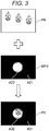
- FIG. 3 is a diagram showing an example of the processing of the projector 1 combining images with each other.
- the processing of combining the images with each other is executed by the OSD generation section 43.
- the input image PB is an example of an image generated based on the video signal input to the OSD generation section 43.
- the composite image PC is obtained by superimposing the mask image MPS on the input image PB.
- the input image PB, the mask image MPS, and the composite image PC are each an image having a plurality of pixels.
- the input image PB is, for example, an RGB 24-bit full-color image, and the data of the input image PB includes grayscale data of R, G, and B for each of the pixels.
- the mask image MPS includes a plurality of areas having respective transmittances T different from each other.
- One area can be constituted by a single pixel, or can also be constituted by a plurality of pixels.
- the positions, the sizes, the shapes of the areas are arbitrary.
- the data of the mask image MPS includes the transmittances T in the respective areas.
- the transmittance T means the extent to which the input image PB is seen through the mask image MPS when the mask image MPS is superimposed as an upper layer of the input image PB, and can also be called transparency.
- the mask image MPS shown in FIG. 3 includes an area A221 and an area A22 in which the respective transmittances T different from each other are set.
- the area A21 is an area in which the transmittance T is set to 0 %.
- the area A22 is an area in which the transmittance T is set to 100 %.
- the mask image MPS can be an image in which the transmittance T changes from 0 % to 100 % between the pixels located on the boundary between the area A21 and the area A22.
- the mask image MPS can be an image forming gradations of the transmittance T gradually varying from 100 % to 0 % in the plurality of pixels located on the boundary portion between the area A21 and the area A22 as illustrated in FIG. 3 . In this case, the transmittances T are set to the respective pixels located on the boundary between the area A21 and the area A22 so that the gradations are formed.
- the mask image MPS is transparent in the area where the transmittance T is 100 %, namely the area A22, and is colored in the area where the transmittance T is lower than 100 %.
- the color is arbitrary, and can be set to, for example, black as shown in FIG. 3 , or can also be other colors. Further, in one mask image MPS, it is possible to dispose a plurality of colors in the area where the transmittance T is lower than 100 %.
- the composite image PC is an image obtained by superimposing the mask image MPS as an upper layer of the input image PB.
- An area A31 of the composite image PC is an area corresponding to the area A21 of the mask image MPS. Since the transmittance T in the area A21 is 0%, the area A31 of the composite image PC is constituted by pixels the same in color as the pixels in the area A21. In contrast, in the composite image PC, in the area where the transmittance T in the mask image MPS is 100 %, the input image PB is transmitted. Therefore, in the area A32, a part of the input image PB appears transmitted through the area A22.
- a part of the input image PB is visually recognized with high brightness, another part is visually recognized with low brightness, and another part is in an invisible state, which has a visual effect as if putting a spotlight on the input image PB.
- This visual effect is called an illumination effect. It is possible for the projector 1 to project the input image PB to the screen SC providing the input image PB with the illumination effect by superimposing the mask image MPS in which the transmittance T is set on the input image PB.
- the OSD generation section 43 is provided with a shape adjustment section 43a and a combining section 43c.
- FIG. 2 is a functional block diagram, and it is possible for the OSD generation section 43 to be provided with hardware functioning as each of the shape adjustment section 43a and the combining section 43c.
- the OSD generation section 43 executes the processing corresponding to the respective functions of the shape adjustment section 43a and the combining section 43c in the order shown in the drawing.
- the shape adjustment section 43a and the combining section 43c can be those schematically showing the functions and the processing to be executed by the OSD generation section 43.
- it is sufficient for the OSD generation section 43 to be what executes the shape adjustment process and the combining process in sequence.
- the shape adjustment section 43a obtains the mask image MPS from the image memory 48, and then executes the processing of adjusting the shape and the size on the mask image MPS. In this processing, the shape and the size of the mask image MPS are made to fit the shape and the size or the resolution of the light modulation device 22.
- the video signal output by the signal processing section 42 to the OSD generation section 43 is adjusted in the shape, the size, and the resolution by the signal processing section 42.
- the shape adjustment section 43a makes the shape, the size, and the resolution of the mask image MPS fit the video signal input from the signal processing section 42. Specifically, the shape, the size, and the resolution of the mask image MPS are made to fit the shape, the size, and the resolution of the input image PB, respectively.
- the combining section 43c combines the mask image MPS adjusted by the shape adjustment section 43a so as to be superimposed as the upper layer of the input image PB input from the signal processing section 42 to thereby generate the composite image PC, and then output the composite image PC to the video correction section 44.
- the OSD generation section 43 provides the input image PB with the illumination effect using the mask image MPS.
- the OSD generation section 43 In order to realize the general OSD display function, it is possible for the OSD generation section 43 to display the OSD image such as the menu screen described above so as to be superimposed on the input image PB.
- the control section 10 outputs the image data of the OSD image to the image input section 47, and the image input section 47 draws the OSD image in the image memory 48.
- the shape adjustment section 43a obtains the OSD image from the image memory 48, and then adjusts the size of the OSD image in accordance with the size and the resolution of the input image PB. The shape and the size of the OSD image are not required to coincide with those of the input image PB.
- the video processing section 40 executes the signal processing on the video signal using the signal processing section 42, and executes the video processing for providing the illumination effect using the OSD generation section 43.
- the video processing related to the input image PB is executed by a different processing section from the OSD generation section 43, namely the signal processing section 42, there is an advantage that the video signal can be processed without being affected by the illumination effect.
- the control section 10 is provided with the luminance adjustment section 111, the determination section 112, the distribution section 113, the first replacement section 121, the second replacement section 122, the third replacement section 123, the fourth replacement section 124, the fifth replacement section 125, the sixth replacement section 126, the seventh replacement section 127, the eighth replacement section 128, the generation section 131, the selection section 132, and the mask storage section 151, but the embodiment of the present disclosure is not limited thereto. It is sufficient for one of the control section 10 shown in FIG.
- the video processing section 40 to be provided with the luminance adjustment section 111, the determination section 112, the distribution section 113, the first replacement section 121, the second replacement section 122, the third replacement section 123, the fourth replacement section 124, the fifth replacement section 125, the sixth replacement section 126, the seventh replacement section 127, the eighth replacement section 128, the generation section 131, the selection section 132, and the mask storage section 151.
- control section 40 it is possible for the control section 40 to be provided with the luminance adjustment section 111, the determination section 112, the distribution section 113, the first replacement section 121, the second replacement section 122, the third replacement section 123, the fourth replacement section 124, the fifth replacement section 125, the sixth replacement section 126, the seventh replacement section 127, the eighth replacement section 128, the generation section 131, the selection section 132, and the mask storage section 151.
- the luminance adjustment section 111, the determination section 112, the distribution section 113, the first replacement section 121, the second replacement section 122, the third replacement section 123, the fourth replacement section 124, the fifth replacement section 125, the sixth replacement section 126, the seventh replacement section 127, the eighth replacement section 128, and the generation section 131 are disposed between, for example, the image input section 47 and the image memory 48 shown in FIG. 2 .
- FIG. 4 is a diagram showing an example of the original image PA. A specific example of the processing of the determination section 112 shown in FIG. 1 will be described with reference to FIG. 4 .
- the original image PA shown in FIG. 4 represents the original image PA adjusted in luminance by the luminance adjustment section 111 shown in FIG. 1 .
- a maximum value of the luminance value B of the original image PA is the maximum luminance value BX
- a minimum value of the luminance value B of the original image PA is the minimum luminance value BN.
- the original image PA includes a first area AR1, a second area AR2, and a third area AR3.
- the third area AR3 is disposed at an outermost side in the original image PA, and includes an outer edge of the original image PA.
- the second area AR2 is disposed inside the third area AR3, and the first area AR1 is disposed inside the second area AR2.
- the luminance value B in the first area AR1 is the first luminance value B1
- the luminance value B in the second area AR2 is the third luminance value B3
- the luminance value B in the third area AR3 is the second luminance value B2.
- the first luminance value B1 is the maximum luminance value BX
- the third luminance value B3 is the minimum luminance value BN
- the second luminance value B2 represents the luminance value B at an intermediate gray level.
- the second luminance value B2 is a constant luminance value B.
- the second luminance value B2 is defined by, for example, the following formula (3).
- B 2 BX + BN / N
- the coefficient N is an integer greater than 1 and no greater than 255.
- the coefficient N is, for example, 2.
- first pixel SP1 On the outer edge of the original image PA, there are disposed a first pixel SP1, a second pixel SP2, a third pixel SP3, a fourth pixel SP4, a fifth pixel SP5, a sixth pixel SP6, a seventh pixel SP7, and an eighth pixel SP8.
- the first pixel SP1, the third pixel SP3, the sixth pixel SP6, and the eighth pixel SP8 are respectively disposed on the four corners of the original image PA having a rectangular shaped.
- the second pixel SP2 is disposed at the middle between the first pixel SP1 and the third pixel SP3.
- the fourth pixel SP4 is disposed at the middle between the first pixel SP1 and the sixth pixel SP6.
- the fifth pixel SP5 is disposed at the middle between the third pixel SP3 and the eighth pixel SP8.
- the seventh pixel SP7 is disposed at the middle between the sixth pixel SP6 and the eighth pixel SP8.
- the determination section 112 determines whether or not at least one of the respective luminance values B of the first pixel SP1 through the eighth pixel SP8 is the second luminance value B2.
- the determination section 112 determines that at least one of the respective luminance values B of the first pixel SP1 through the eighth pixel SP8 is the second luminance value B2.
- the determination section 112 determines whether or not at least one of the respective luminance values B of the first pixel SP1 through the eighth pixel SP8 is the second luminance value B2, but the embodiment of the present disclosure is not limited thereto. It is sufficient for the determination section 112 to determine whether or not the luminance value B of the pixel SP constituting the outer edge of the original image PA is the second luminance value B2.
- the number of the pixels SP used by the determination section 112 for the determination can be one, or can also be two or more.
- FIG. 5 is a diagram showing an example of the processing of the first replacement section 121 and the second replacement section 122.
- the upper drawing in FIG. 5 shows an example of the original image PA.
- the original image PA is the same image as the original image PA shown in FIG. 4 .
- the lower right drawing in FIG. 5 shows an example of the first image P1 to be generated by the first replacement section 121.
- the first replacement section 121 replaces the luminance values B of the pixels corresponding to the second luminance value B2 with the third luminance value B3 in the original image PA to generate the first image P1.
- the pixels corresponding to the second luminance value B2 represent the pixels included in the third area AR3. Therefore, the first replacement section 121 replaces the second luminance value B2 as the luminance values B of the pixels included in the third area AR3 with the third luminance value B3 to generate the first image P1. As a result, the first image P1 shown in the lower right drawing in FIG. 5 is generated.
- the first image P1 includes the first area AR1, the second area AR2, and the third area AR3.
- the luminance value B in the first area AR1 is the first luminance value B1
- the luminance value B in the second area AR2 is the third luminance value B3
- the luminance value B in the third area AR3 is the third luminance value B3.
- the lower left drawing in FIG. 5 shows an example of the second image P2 to be generated by the second replacement section 122.
- the second replacement section 122 replaces the luminance values B of the pixels corresponding to the second luminance value B2 with the first luminance value B1 in the original image PA to generate the second image P2.
- the second replacement section 122 replaces the second luminance value B2 as the luminance values B of the pixels included in the third area AR3 with the first luminance value B1 to generate the second image P2.
- the second image P2 shown in the lower left drawing in FIG. 5 is generated.
- the second image P2 includes the first area AR1, the second area AR2, and the third area AR3.
- the luminance value B in the first area AR1 is the first luminance value B1
- the luminance value B in the second area AR2 is the third luminance value B3
- the luminance value B in the third area AR3 is the first luminance value B1.
- FIG. 6 is a diagram showing an example of the processing of the third replacement section 123 and the fourth replacement section 124.
- the upper drawing in FIG. 6 shows an example of the original image PA.
- the original image PA is the same image as the original image PA shown in FIG. 4 .
- the lower right drawing in FIG. 6 shows an example of the third image P3 to be generated by the third replacement section 123.
- the third replacement section 123 replaces the luminance values B of the pixels corresponding to the second luminance value B2 with the third luminance value B3, and at the same time, replaces the luminance values B of the pixels corresponding to the third luminance value B3 with the second luminance value B2 in the original image PA to generate the third image P3.
- the pixels corresponding to the second luminance value B2 represent the pixels included in the third area AR3. Further, in the original image PA, the pixels corresponding to the third luminance value B3 represent the pixels included in the second area AR2. Therefore, the third replacement section 123 replaces the second luminance value B2 as the luminance values B of the pixels included in the third area AR3 with the third luminance value B3, and at the same time, replaces the third luminance value B3 as the luminance values B of the pixels included in the second area AR2 with the second luminance value B2 to generate the third image P3. As a result, the third image P3 shown in the lower right drawing in FIG. 6 is generated.
- the third image P3 includes the first area AR1, the second area AR2, and the third area AR3.
- the luminance value B in the first area AR1 is the first luminance value B1
- the luminance value B in the second area AR2 is the second luminance value B2
- the luminance value B in the third area AR3 is the third luminance value B3.
- the lower left drawing in FIG. 6 shows an example of the fourth image P4 to be generated by the fourth replacement section 124.
- the fourth replacement section 124 replaces the luminance values B of the pixels corresponding to the second luminance value B2 with the first luminance value B1, and at the same time, replaces the luminance values B of the pixels corresponding to the first luminance value B1 with the second luminance value B2 in the original image PA to generate the fourth image P4.
- the pixels corresponding to the second luminance value B2 represent the pixels included in the third area AR3. Further, in the original image PA, the pixels corresponding to the first luminance value B1 represent the pixels included in the first area AR1. Therefore, the fourth replacement section 124 replaces the second luminance value B2 as the luminance values B of the pixels included in the third area AR3 with the first luminance value B1, and at the same time, replaces the first luminance value B1 as the luminance values B of the pixels included in the first area AR1 with the second luminance value B2 to generate the fourth image P4. As a result, the fourth image P4 shown in the lower left drawing in FIG. 6 is generated.
- the fourth image P4 includes the first area AR1, the second area AR2, and the third area AR3.
- the luminance value B in the first area AR1 is the second luminance value B2
- the luminance value B in the second area AR2 is the third luminance value B3
- the luminance value B in the third area AR3 is the first luminance value B1.
- FIG. 7 is a diagram showing an example of the processing of the fifth replacement section 125 and the sixth replacement section 126.
- the upper right drawing in FIG. 7 shows an example of the first image P1.
- the first image P1 is the same image as the first image P1 shown in FIG. 5 .
- the lower right drawing in FIG. 7 shows an example of the fifth image P5 to be generated by the fifth replacement section 125.
- the fifth replacement section 125 replaces the luminance values B of the pixels corresponding to the third luminance value B3 with the first luminance value B1, and at the same time, replaces the luminance values B of the pixels corresponding to the first luminance value B1 with the third luminance value B3 in the first image P1 to generate the fifth image P5.
- the fifth replacement section 125 reverses the luminance values B in the first image P1 to thereby generate the fifth image P5.
- the pixels corresponding to the third luminance value B3 represent the pixels included in the second area AR2, and the pixels included in the third area AR3.
- the pixels corresponding to the first luminance value B1 represent the pixels included in the first area AR1. Therefore, the fifth replacement section 125 replaces the third luminance value B3 as the luminance values B of the pixels included in the second area AR2 and the pixels included in the third area AR3 with the first luminance value B1, and at the same time, replaces the first luminance value B1 as the luminance values B of the pixels included in the first area AR1 with the third luminance value B3 to generate the fifth image P5. As a result, the fifth image P5 shown in the lower right drawing in FIG. 7 is generated.
- the fifth image P5 includes the first area AR1, the second area AR2, and the third area AR3.
- the luminance value B in the first area AR1 is the third luminance value B3
- the luminance value B in the second area AR2 is the first luminance value B1
- the luminance value B in the third area AR3 is the first luminance value B1.
- the upper left drawing in FIG. 7 shows an example of the second image P2.
- the second image P2 is the same image as the second image P2 shown in FIG. 5 .
- the lower left drawing in FIG. 7 shows an example of the sixth image P6 to be generated by the sixth replacement section 126.
- the sixth replacement section 126 replaces the luminance values B of the pixels corresponding to the third luminance value B3 with the first luminance value B1, and at the same time, replaces the luminance values B of the pixels corresponding to the first luminance value B1 with the third luminance value B3 in the second image P2 to generate the sixth image P6.
- the sixth replacement section 126 reverses the luminance values B in the second image P2 to thereby generate the sixth image P6.
- the pixels corresponding to the third luminance value B3 represent the pixels included in the second area AR2.
- the pixels corresponding to the first luminance value B1 represent the pixels included in the first area AR1, and the pixels included in the third area AR3. Therefore, the sixth replacement section 126 replaces the third luminance value B3 as the luminance values B of the pixels included in the second area AR2 with the first luminance value B1, and at the same time, replaces the first luminance value B1 as the luminance values B of the pixels included in the first area AR1 and the pixels included in the third area AR3 with the third luminance value B3 to generate the sixth image P6. As a result, the sixth image P6 shown in the lower left drawing in FIG. 7 is generated.
- the sixth image P6 includes the first area AR1, the second area AR2, and the third area AR3.
- the luminance value B in the first area AR1 is the third luminance value B3
- the luminance value B in the second area AR2 is the first luminance value B1
- the luminance value B in the third area AR3 is the third luminance value B3.
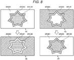
- FIG. 8 is a diagram showing an example of the processing of the seventh replacement section 127 and the eighth replacement section 128.
- the upper right drawing in FIG. 8 shows an example of the third image P3.
- the third image P3 is the same image as the third image P3 shown in FIG. 6 .
- the lower right drawing in FIG. 8 shows an example of the seventh image P7 to be generated by the seventh replacement section 127.
- the seventh replacement section 127 replaces the luminance values B of the pixels corresponding to the third luminance value B3 with the first luminance value B1, and at the same time, replaces the luminance values B of the pixels corresponding to the first luminance value B1 with the third luminance value B3 in the third image P3 to generate the seventh image P7.
- the seventh replacement section 127 reverses the luminance values B in the third image P3 to thereby generate the seventh image P7.
- the pixels corresponding to the third luminance value B3 represent the pixels included in the third area AR3.
- the pixels corresponding to the first luminance value B1 represent the pixels included in the first area AR1. Therefore, the seventh replacement section 127 replaces the third luminance value B3 as the luminance values B of the pixels included in the third area AR3 with the first luminance value B1, and at the same time, replaces the first luminance value B1 as the luminance values B of the pixels included in the third area AR3 with the third luminance value B3 to generate the seventh image P7.
- the seventh image P7 shown in the lower right drawing in FIG. 8 is generated.
- the seventh image P7 includes the first area AR1, the second area AR2, and the third area AR3.
- the luminance value B in the first area AR1 is the third luminance value B3
- the luminance value B in the second area AR2 is the second luminance value B2
- the luminance value B in the third area AR3 is the first luminance value B1.
- the upper left drawing in FIG. 8 shows an example of the fourth image P4.
- the fourth image P4 is the same image as the fourth image P4 shown in FIG. 6 .
- the lower left drawing in FIG. 8 shows an example of the eighth image P8 to be generated by the eighth replacement section 128.
- the eighth replacement section 128 replaces the luminance values B of the pixels corresponding to the third luminance value B3 with the first luminance value B1, and at the same time, replaces the luminance values B of the pixels corresponding to the first luminance value B1 with the third luminance value B3 in the fourth image P4 to generate the eighth image P8.
- the eighth replacement section 128 reverses the luminance values B in the fourth image P4 to thereby generate the eighth image P8.
- the pixels corresponding to the third luminance value B3 represent the pixels included in the second area AR2.
- the pixels corresponding to the first luminance value B1 represent the pixels included in the third area AR3. Therefore, the eighth replacement section 128 replaces the third luminance value B3 as the luminance values B of the pixels included in the second area AR2 with the first luminance value B1, and at the same time, replaces the first luminance value B1 as the luminance values B of the pixels included in the third area AR3 with the third luminance value B3 to generate the eighth image P8.
- the eighth image P8 shown in the lower left drawing in FIG. 8 is generated.
- the eighth image P8 includes the first area AR1, the second area AR2, and the third area AR3.
- the luminance value B in the first area AR1 is the second luminance value B2
- the luminance value B in the second area AR2 is the first luminance value B1
- the luminance value B in the third area AR3 is the third luminance value B3.
- FIG. 9 is a diagram showing an example of the processing of the generation section 131 and the combining section 43c.
- the upper left drawing in FIG. 9 shows an example of the input image PB to be input from the signal processing section 42 shown in FIG. 2 .
- the input image PB includes a first penguin image PG1, a second penguin image PG2, and a third penguin image PG3.
- the lower left drawing in FIG. 9 shows the second mask image MP2 as an example of the mask image MPS.
- the generation section 131 converts the luminance value B of each of the pixels of the second image P2 shown in FIG. 5 into the transmittance T to generate the second mask image MP2.
- the generation section 131 converts the luminance value B into the transmittance T so that the higher the luminance value B is, the higher the transmittance T is.
- the generation section 131 converts the first luminance value B1 into a first transmittance T1, converts the second luminance value B2 into a second transmittance T2, and converts the third luminance value B3 into a third transmittance T3.
- the first transmittance T1 is higher than the second transmittance T2, and the second transmittance T2 is higher than the third transmittance T3.
- the first transmittance T1 represents the fact that, for example, the transmittance T is 100 %
- the second transmittance T2 represents the fact that, for example, the transmittance T is 50 %
- the third transmittance T3 represents the fact that, for example, the transmittance T is 0 %.
- the second mask image MP2 shown in the lower left drawing in FIG. 9 includes the first area AR1, the second area AR2, and the third area AR3.
- the transmittance T in the first area AR1 is the first transmittance T1
- the transmittance T in the second area AR2 is the third transmittance T3
- the transmittance T in the third area AR3 is the first transmittance T1.
- the combining section 43c combines the input image PB and the second mask image MP2 so as to be superimposed on each other to generate the composite image PC.
- the right drawing in FIG. 9 shows an example of the composite image PC. Since the transmittance T in the first area AR1 and the third area AR3 is the first transmittance T1 in the second mask image MP2, the input image PB is visually recognized in the first area AR1 and the third area AR3. In contrast, since the transmittance T in the second area AR2 is the third transmittance T3 in the second mask image MP2, the input image PB cannot visually be recognized. As a result, the third penguin image PG3 included in the input image PB can visually be recognized, but a part of the first penguin image PG1 and a part of the second penguin image PG2 included in the input image PB cannot visually be recognized.
- FIG. 10 is a diagram showing another example of the processing of the generation section 131 and the combining section 43c.
- FIG. 10 is different in that the selection section 132 selects the eighth mask image MP8 from FIG. 9 in which the selection section 132 selects the second mask image MP2.
- the difference from FIG. 9 will mainly be described.
- the lower left drawing in FIG. 10 shows the eighth mask image MP8 as an example of the mask image MPS.
- the generation section 131 converts the luminance value B of each of the pixels of the eighth image P8 into the transmittance T to generate the eighth mask image MP8.
- the eighth mask image MP8 shown in the lower left drawing in FIG. 10 includes the first area AR1, the second area AR2, and the third area AR3.
- the transmittance T in the first area AR1 is the second transmittance T2
- the transmittance T in the second area AR2 is the first transmittance T1
- the transmittance T in the third area AR3 is the third transmittance T3.
- the combining section 43c combines the input image PB and the eighth mask image MP8 so as to be superimposed on each other to generate the composite image PC.
- the right drawing in FIG. 10 shows an example of the composite image PC. Since the transmittance T in the second area AR2 is the first transmittance T1 in the eighth mask image MP8, the input image PB is visually recognized in the second area AR2. Further, since the transmittance T in the first area AR1 is the second transmittance T2, the input image PB is visually recognized more darkly than in the second area AR2. In contrast, since the transmittance T in the third area AR3 is the third transmittance T3 in the eighth mask image MP8, the input image PB cannot visually be recognized. As a result, the first penguin image PG1 and the second penguin image PG2 included in the input image PB cannot be recognized, and the third penguin image PG3 can visually be recognized darkly.
- FIG. 11 and FIG. 12 are a flowchart showing an example of the processing of the control section 10 and the video processing section 40.
- the luminance adjustment section 111 obtains the luminance distribution of the original image PA. Specifically, the luminance adjustment section 111 obtains the first luminance value BA1 and the third luminance value BA3.
- the first luminance value BA1 represents the highest one of the luminance values BA of the pixels constituting the original image PA.
- the third luminance value BA3 represents the lowest one of the luminance values BA of the pixels constituting the original image PA.
- the luminance adjustment section 111 adjusts the luminance value BA of the pixels constituting the original image PA into the luminance value B so that the first luminance value BA1 of the pixel of the original image PA becomes the maximum luminance value BX, and the third luminance value BA3 of the pixel of the original image PA becomes the minimum luminance value BN.
- the determination section 112 obtains the luminance values B of the pixels constituting the outer edge of the original image PA.
- the determination section 112 determines whether or not the luminance values B of the pixels constituting the outer edge of the original image PA are the maximum luminance value BX.
- the process proceeds to the step S111.
- the determination section 112 has determined that the luminance values B of the pixels constituting the outer edge of the original image PA are not the maximum luminance value BX (NO in the step S107)
- the process proceeds to the step S109.
- the determination section 112 determines whether or not the luminance values B of the pixels constituting the outer edge of the original image PA are the minimum luminance value BN.
- the process proceeds to the step S111.
- the generation section 131 converts the luminance value B of each of the pixels in the original image PA into the transmittance T to generate the mask image MPA, and then records the mask image MPA thus generated on the mask storage section 151. Subsequently, the process proceeds to the step S135 shown in FIG. 12 .
- the process proceeds to the step S113.
- the distribution section 113 distributes the luminance values B of the pixels of the original image PA into the first luminance value B1, the second luminance value B2, and the third luminance value B3.
- the first luminance value B1 is the maximum luminance value BX
- the third luminance value B3 is the minimum luminance value BN
- the second luminance value B2 represents the luminance value B at an intermediate gray level.
- the first replacement section 121 executes a first replacement process to generate the first image P1.
- the first replacement process represents the processing of replacing the luminance values B of the pixels corresponding to the second luminance value B2 in the original image PA with the third luminance value B3.
- the second replacement section 122 executes a second replacement process to generate the second image P2.
- the second replacement process represents the processing of replacing the luminance values B of the pixels corresponding to the second luminance value B2 in the original image PA with the first luminance value B1.
- the third replacement section 123 executes a third replacement process to generate the third image P3.
- the third replacement process represents the processing of replacing the luminance values B of the pixels corresponding to the second luminance value B2 in the original image PA with the third luminance value B3, and at the same time, replacing the luminance values B of the pixels corresponding to the third luminance value B3 with the second luminance value B2.
- the fourth replacement section 124 executes a fourth replacement process to generate the fourth image P4.
- the fourth replacement process represents the processing of replacing the luminance values B of the pixels corresponding to the second luminance value B2 in the original image PA with the first luminance value B1, and at the same time, replacing the luminance values B of the pixels corresponding to the first luminance value B1 with the second luminance value B2.
- the fifth replacement section 125 executes a fifth replacement process to generate the fifth image P5.
- the fifth replacement process represents the processing of replacing the luminance values B of the pixels corresponding to the third luminance value B3 in the first image P1 with the first luminance value B1, and at the same time, replacing the luminance values B of the pixels corresponding to the first luminance value B1 with the third luminance value B3.
- the sixth replacement section 126 executes a sixth replacement process to generate the sixth image P6.
- the sixth replacement process represents the processing of replacing the luminance values B of the pixels corresponding to the third luminance value B3 in the second image P2 with the first luminance value B1, and at the same time, replacing the luminance values B of the pixels corresponding to the first luminance value B1 with the third luminance value B3.
- the seventh replacement section 127 executes a seventh replacement process to generate the seventh image P7.
- the seventh replacement process represents the processing of replacing the luminance values B of the pixels corresponding to the third luminance value B3 in the third image P3 with the first luminance value B1, and at the same time, replacing the luminance values B of the pixels corresponding to the first luminance value B1 with the third luminance value B3.
- the eighth replacement section 128 executes an eighth replacement process to generate the eighth image P8.
- the eighth replacement process represents the processing of replacing the luminance values B of the pixels corresponding to the third luminance value B3 in the fourth image P4 with the first luminance value B1, and at the same time, replacing the luminance values B of the pixels corresponding to the first luminance value B1 with the third luminance value B3.
- the generation section 131 converts the luminance values B of the pixels into the transmittances T with respect to the first image P1 through the eighth image P8 to generate the first mask image MP1 through the eighth mask image MP8, and then records the first mask image MP1 through the eighth mask image MP8 on the mask storage section 151.
- the selection section 132 selects a mask image MPS from the first mask image MP1 through the eighth mask image MP8 based on the operation from the user.
- the combining section 43c superimposes the mask image MPS on the input image PB input from the signal processing section 42 to thereby combine the input image PB and the mask image MPS with each other to generate the composite image PC.
- control section 10 projects the composite image PC to the screen SC via the image forming section 20.
- control section 10 determines whether or not the display of the composite image PC to the screen SC is to be terminated.
- control section 10 When the control section 10 has determined that the display of the composite image PC to the screen SC is not terminated (NO in the step S139), the process returns to the step S135. When the control section 10 has determined that the display of the composite image PC to the screen SC is to be terminated (YES in the step S139), the process terminates.
- the step S107 and the step S109 correspond to an example of a "determining step.”
- the step S113 corresponds to an example of a "distributing step.”
- the step S115 corresponds to an example of a "first replacing step.”
- the step S117 corresponds to an example of a "second replacing step.”
- the step S119 corresponds to an example of a "third replacing step.”
- the step S121 corresponds to an example of a "fourth replacing step.”
- the step S123 corresponds to an example of a "fifth replacing step.”
- the step S125 corresponds to an example of a "sixth replacing step.”
- the step S127 corresponds to an example of a "seventh replacing step.”
- the step S129 corresponds to an example of an "eighth replacing step.”
- the step S111 and the step S131 each correspond to an example of a "generating step.”
- the method of controlling the projector 1 includes the distributing step of distributing each of the luminance values B of the plurality of pixels constituting the original image PA into the first luminance value B1, the second luminance value B2 lower than the first luminance value B1, and the third luminance value B3 lower than the second luminance value B2, the first replacing step of replacing the luminance values B of the pixels corresponding to the second luminance value B2 with the third luminance value B3 in the original image PA to generate the first image P1, the second replacing step of replacing the luminance values B of the pixels corresponding to the second luminance value B2 with the first luminance value B1 in the original image PA to generate the second image P2, and the generating step of converting the luminance values B of the pixels into the transmittances T in each of the first image P1 and the second image P2 to generate the mask images MP.
- the luminance values B of the pixels corresponding to the second luminance value B2 are replaced with the third luminance value B3 in the original image PA to generate the first image P1
- the luminance values B of the pixels corresponding to the second luminance value B2 are replaced with the first luminance value B1 in the original image PA to generate the second image P2
- the mask image MP is generated by converting the luminance values B of the pixels into the transmittances T in each of the first image P1 and the second image P2, it is possible to generate the mask images MP each consisting of the pixels the transmittances T of which are the first transmittance T1 corresponding to the first luminance value B1 and the pixels the transmittances T of which are the third transmittance T3 corresponding to the third luminance value B3. Therefore, it is possible to increase the possibility of generating the mask image MP desired by the user.
- the luminance values B of the pixels corresponding to the second luminance value B2 are replaced with the third luminance value B3, and at the same time, the luminance values B of the pixels corresponding to the third luminance value B3 are replaced with the second luminance value B2 in the original image PA to generate the third image P3, it is possible to generate the third image P3 in which the luminance values B in an area including the outer edge are the third luminance value B3 when, for example, the luminance values B in an area including the outer edge of the original image PA are the second luminance value B2.
- the luminance values B of the pixels corresponding to the second luminance value B2 are replaced with the first luminance value B1
- the luminance values B of the pixels corresponding to the first luminance value B1 are replaced with the second luminance value B2 in the original image PA to generate the fourth image P4
- the mask image MP is generated by converting the luminance values B of the pixels into the transmittances T in each of the third image P3 and the fourth image P4, it is possible to generate the mask images MP in which the transmittances T in the area including the outer edge are the first transmittance T1 corresponding to the first luminance value B1 or the third transmittance T3 corresponding to the third luminance value B3. Therefore, it is possible to further increase the possibility of generating the mask image MP desired by the user.
- the luminance values B of the pixels corresponding to the third luminance value B3 are replaced with the first luminance value B1, and at the same time, the luminance values B of the pixels corresponding to the first luminance value B1 are replaced with the third luminance value B3 in the first image P1 to generate the fifth image P5, and the luminance values B of the pixels corresponding to the third luminance value B3 are replaced with the first luminance value B1, and at the same time, the luminance values B of the pixels corresponding to the first luminance value B1 are replaced with the third luminance value B3 in the second image P2 to generate the sixth image P6, it is possible to generate the fifth image P5 and the sixth image P6 each consisting of the pixels the luminance values B of which are the first luminance value B1 and the pixels the luminance values B of which are the third luminance value B3.
- the mask image MP is generated by converting the luminance values B of the pixels into the transmittances T in each of the fifth image P5 and the sixth image P6, it is possible to generate the mask images MP each consisting of the pixels the transmittances T of which are the first transmittance T1 corresponding to the first luminance value B1 and the pixels the transmittances T of which are the third transmittance T3 corresponding to the third luminance value B3. Therefore, it is possible to increase the possibility of generating the mask image MP desired by the user.
- the luminance values B of the pixels corresponding to the third luminance value B3 are replaced with the first luminance value B1
- the luminance values B of the pixels corresponding to the first luminance value B1 are replaced with the third luminance value B3 in the third image P3 to generate the seventh image P7
- the luminance values B of the pixels corresponding to the third luminance value B3 are replaced with the first luminance value B1
- the luminance values B of the pixels corresponding to the first luminance value B1 are replaced with the third luminance value B3 in the fourth image P4 to generate the eighth image P8
- the mask image MP is generated by converting the luminance values B of the pixels into the transmittances T in each of the seventh image P7 and the eighth image P8, it is possible to generate the mask images MP in which the transmittances T in the area including the outer edge are the first transmittance T1 corresponding to the first luminance value B1 or the third transmittance T3 corresponding to the third luminance value B3. Therefore, it is possible to further increase the possibility of generating the mask image MP desired by the user.
- the first luminance value B1 represents the maximum luminance value BX
- the third luminance value B3 represents the minimum luminance value BN.
- the luminance values B of the pixels are converted into the transmittances T in each of the first image P1 and the second image P2 to generate the mask images MP. Therefore, it is possible to generate the mask images MP each consisting of the pixels the transmittances T of which correspond to the maximum luminance value BX and the pixels the transmittance T of which correspond to the minimum luminance value BN. Therefore, it is possible to increase the possibility of generating the mask image desired by the user.
- the luminance values B of the pixels constituting the outer edge of the original image PA are not the second luminance value B2, namely when the luminance values B of the pixels constituting the outer edge of the original image PA are the first luminance value B1 or the third luminance value B3, the luminance values B of the pixels are converted into the transmittances T in the original image PA to generate the mask image MP. Therefore, it is possible to generate the mask image MP in which the transmittance T in the area including the outer edge is the first transmittance T1 corresponding to the first luminance value B1 or the third transmittance T3 corresponding to the third luminance value B3. As a result, it is possible to increase the possibility of generating the mask image MP desired by the user.
- the projector 1 is provided with the distribution section 113 for distributing each of the luminance values B of the plurality of pixels constituting the original image PA into the first luminance value B1, the second luminance value B2 lower than the first luminance value B1, and the third luminance value B3 lower than the second luminance value B2, the first replacement section 121 for replacing the luminance values B of the pixels corresponding to the second luminance value B2 with the third luminance value B3 in the original image PA to generate the first image P1, the second replacement section 122 for replacing the luminance values B of the pixels corresponding to the second luminance value B2 with the first luminance value B1 in the original image PA to generate the second image P2, and the generation section 131 for converting the luminance values B of the pixels into the transmittances T in each of the first image P1 and the second image P2 to generate the mask images MP.
- the luminance values B of the pixels corresponding to the second luminance value B2 are replaced with the third luminance value B3 in the original image PA to generate the first image P1
- the luminance values B of the pixels corresponding to the second luminance value B2 are replaced with the first luminance value B1 in the original image PA to generate the second image P2
- the mask image MP is generated by converting the luminance values B of the pixels into the transmittances T in each of the first image P1 and the second image P2, it is possible to generate the mask images MP each consisting of the pixels the transmittances T of which are the first transmittance T1 corresponding to the first luminance value B1 and the pixels the transmittances T of which are the third transmittance T3 corresponding to the third luminance value B3. Therefore, it is possible to increase the possibility of generating the mask image MP desired by the user.
- the "display device” is the projector 1, but the embodiment of the present disclosure is not limited thereto. It is sufficient for the “display device” to generate the composite image PC obtained by combining the mask image MP and the input image PB with each other, and then display the composite image PC. It is possible for the “display device” to be formed of, for example, an LCD (Liquid Crystal Display).
- LCD Liquid Crystal Display
- the luminance adjustment section 111 adjusts the luminance values BA of the pixels of the original image PA so that the first luminance value BA1 of the pixel of the original image PA becomes the maximum luminance value BX, and the third luminance value BA3 of the pixel of the original image PA becomes the minimum luminance value BN, and then generates each of the first image P1 through the eighth image P8, but the embodiment of the present disclosure is not limited thereto. It is possible for the luminance adjustment section 111 to generate each of the first image P1 through the eighth image P8 without adjusting the luminance values BA of the pixels of the original image PA. In this case, the processing can be simplified.
- each of the first image P1 through the eighth image P8 is generated based on the original image PA
- the embodiment of the present disclosure is not limited thereto. It is sufficient to generate at least the first image P1 and the second image P2 based on the original image PA. It is also possible to generate, for example, each of the first image P1 through the fourth image P4 based on the original image PA. Further, it is possible to generate each of the first image P1, the second image P2, the fifth image P5, and the sixth image P6 based on the original image PA.
- the generation section 131 converts the luminance value B into the transmittance T so that the higher the luminance value B is, the higher the transmittance T is
- the embodiment of the present disclosure is not limited thereto. It is sufficient for the generation section 131 to convert the luminance value B into the transmittance T. It is possible for the generation section 131 to convert the luminance value B into the transmittance T so that, for example, the higher the luminance value B is, the lower the transmittance T is.
- each of the functional sections shown in FIG. 1 and FIG. 2 represents the functional configuration, and the specific implementation configuration is not particularly limited. In other words, it is not necessarily required to install the hardware individually corresponding to each of the functional sections, but it is obviously possible to adopt a configuration of realizing the functions of the plurality of functional sections by a single processor executing a program. Further, a part of the function realized by software in the embodiment described above can also be realized by hardware, or a part of the function realized by hardware can also be realized by software. Besides the above, the specific detailed configuration of each of other sections of the projector 1 can arbitrarily be modified within the scope or the spirit.
- the processing units of the flowcharts shown in FIG. 11 and FIG. 12 are obtained by dividing the process of the projector 200 in accordance with major processing contents in order to make the process of the projector 1 easy to understand.
- the way of division or the names of the processing units shown in the flowchart in FIG. 11 and FIG. 12 are not a limitation, and it is also possible to divide the processing into a larger number of processing units, or it is also possible to divide the processing so that one processing unit includes a larger amount of processing in accordance with the processing contents.
- the processing sequence of the flowchart described above is not limited to the illustrated example.
- the method of controlling the projector 1 can be realized by making the processor 10A provided to the projector 1 execute the program corresponding to the method of controlling the projector 1. Further, it is also possible to record the program on a recording medium storing the program in a computer readable manner.
- a recording medium there can be used a magnetic or optical recording medium, or a semiconductor memory device.
- a portable or rigid recording medium such as a flexible disk, an HDD (Hard Disk Drive), a CD-ROM (Compact Disc Read Only Memory), a DVD (Digital Versatile Disc), a Blu-ray (registered trademark) disc, a magnetooptic disc, a flash memory, or a card-type recording medium.
- the recording medium can also be a RAM (Random Access Memory) as an internal storage device provided to the image processing device, or a nonvolatile storage device such as a ROM (Read Only Memory) or the HDD. Further, it is also possible to realize the method of controlling the projector 1 by storing the program corresponding to the method of controlling the projector 1 in a server device or the like in advance, and then downloading the program from the server device to the projector 1.
- RAM Random Access Memory
- ROM Read Only Memory
Landscapes
- Engineering & Computer Science (AREA)
- Physics & Mathematics (AREA)
- Computer Hardware Design (AREA)
- General Physics & Mathematics (AREA)
- Theoretical Computer Science (AREA)
- Multimedia (AREA)
- Signal Processing (AREA)
- Chemical & Material Sciences (AREA)
- Crystallography & Structural Chemistry (AREA)
- Controls And Circuits For Display Device (AREA)
- Control Of Indicators Other Than Cathode Ray Tubes (AREA)
- Transforming Electric Information Into Light Information (AREA)
Abstract
Description
- The present disclosure relates to a method of controlling a display device and a display device.
- There has been known a display device, which combines a composite target image and a mask image with each other to generate a composite image, and then displays the composite image thus generated (see, e.g.,
JP-A-2019-32395 - The projector described in
Document 1 has an image processing section for combining a first image based on first image information and a second image generated by converting luminance information of second image information having the luminance information into transmittance with each other based on the transmittance to thereby generate a third image, and an image forming section for displaying the third image. - In the display device described in
Document 1, when the luminance values of the pixels constituting an original image of the mask image include an intermediate gray level, the luminance value of the intermediate gray level is converted into the transmittance of the intermediate gray level, and therefore, there is a possibility that the mask image desired by the user fails to be generated. - An aspect for solving the problem described above is directed to a method of controlling a display device including a distributing step of distributing each of luminance values of a plurality of pixels constituting an original image into a first luminance value, a second luminance value lower than the first luminance value, and a third luminance value lower than the second luminance value, a first replacing step of replacing the luminance values of the pixels corresponding to the second luminance value with the third luminance value in the original image to generate a first image, a second replacing step of replacing the luminance values of the pixels corresponding to the second luminance value with the first luminance value in the original image to generate a second image, and a generating step of converting the luminance values of the pixels into transmittances in each of the first image and the second image to generate mask images.
- The method of controlling a display device described above may further include a third replacing step of replacing the luminance values of the pixels corresponding to the second luminance value with the third luminance value, and replacing the luminance values of the pixels corresponding to the third luminance value with the second luminance value in the original image to generate a third image, and a fourth replacing step of replacing the luminance values of the pixels corresponding to the second luminance value with the first luminance value, and replacing the luminance values of the pixels corresponding to the first luminance value with the second luminance value in the original image to generate a fourth image, wherein in the generating step, the luminance values of the pixels may be converted into transmittances in each of the third image and the fourth image to generate mask images.
- The method of controlling a display device described above may further include a fifth replacing step of replacing the luminance values of the pixels corresponding to the third luminance value with the first luminance value, and replacing the luminance values of the pixels corresponding to the first luminance value with the third luminance value in the first image to generate a fifth image, and a sixth replacing step of replacing the luminance values of the pixels corresponding to the third luminance value with the first luminance value, and replacing the luminance values of the pixels corresponding to the first luminance value with the third luminance value in the second image to generate a sixth image, wherein in the generating step, the luminance values of the pixels may be converted into transmittances in each of the fifth image and the sixth image to generate mask images.
- The method of controlling a display device described above may further include a seventh replacing step of replacing the luminance values of the pixels corresponding to the third luminance value with the first luminance value, and replacing the luminance values of the pixels corresponding to the first luminance value with the third luminance value in the third image to generate a seventh image, and an eighth replacing step of replacing the luminance values of the pixels corresponding to the third luminance value with the first luminance value, and replacing the luminance values of the pixels corresponding to the first luminance value with the third luminance value in the fourth image to generate an eighth image, wherein in the generating step, the luminance values of the pixels may be converted into transmittances in each of the seventh image and the eighth image to generate mask images.
- In the method of controlling a display device described above, the first luminance value may represent a maximum luminance value, and the third luminance value may represent a minimum luminance value.
- In the method of controlling a display device described above, there may further be included a determining step of determining whether or not the luminance values of the pixels constituting an outer edge of the original image are the second luminance value, wherein when it was determined in the determining step that the luminance values of the pixels constituting the outer edge of the original image were not the second luminance value, the luminance values of the pixels may be converted, in the generating step, into the transmittances in the original image to generate the mask image.
- Another aspect for solving the problem described above is directed to a display device including a distribution section configured to distribute each of luminance values of a plurality of pixels constituting an original image into a first luminance value, a second luminance value lower than the first luminance value, and a third luminance value lower than the second luminance value, a first replacement section configured to replace the luminance values of the pixels corresponding to the second luminance value with the third luminance value in the original image to generate a first image, a second replacement section configured to replace the luminance values of the pixels corresponding to the second luminance value with the first luminance value in the original image to generate a second image, and a generation section configured to convert the luminance values of the pixels into transmittances in each of the first image and the second image to generate mask images.
-
-
FIG. 1 is a diagram showing an example of a configuration of a projector. -
FIG. 2 is a diagram showing an example of a configuration of an image processing section. -
FIG. 3 is a diagram showing an example of processing of the projector combining images with each other. -
FIG. 4 is a diagram showing an example of an original image. -
FIG. 5 is a diagram showing an example of processing of a first replacement section and a second replacement section. -
FIG. 6 is a diagram showing an example of processing of a third replacement section and a fourth replacement section. -
FIG. 7 is a diagram showing an example of processing of a fifth replacement section and a sixth replacement section. -
FIG. 8 is a diagram showing an example of processing of a seventh replacement section and an eighth replacement section. -
FIG. 9 is a diagram showing an example of processing of a generation section and a combining section. -
FIG. 10 is a diagram showing another example of the processing of the generation section and the combining section. -
FIG. 11 is a flowchart showing an example of processing of a control section and an image processing section. -
FIG. 12 is a flowchart showing an example of the processing of the control section and the image processing section. - An embodiment will hereinafter be described with reference to the drawings.
-
FIG. 1 is a diagram showing an example of a configuration of aprojector 1. - The
projector 1 is a display device which projects image light to a screen SC to thereby display a projection image PP on the screen SC by means of projection. It is also possible for theprojector 1 to project either of a still image and a video picture, namely a moving image, as the projection image PP, and in the following description, there is used the description of "video" or "image." Since theprojector 1 updates the projection image PP at a preset frame rate with animage forming section 20 even when projecting a still image, there is no difference in the actual action between a still image and a video picture. - The screen SC can be a curtain-like screen to be installed on a wall surface, a ceiling surface, or a floor surface in a room of a building, but it is possible to use the wall surface as the screen SC. Further, it is also possible to utilize a plane of an installation such as a whiteboard or furniture as the screen SC. Further, the screen SC is not limited to a plane, but can also be a curved surface or a surface having asperity.
- The
projector 1 can use video data stored in a memory 10B described later as a video source of the projection image PP. Further, the video source of theprojector 1 can be selected from a video signal input to theprojector 1 from thevideo supply device 2, video data input to theprojector 1 from adata output device 3, video data stored in astorage medium 4, and so on. - The
video supply device 2 is coupled to theprojector 1 via a cable or a wireless communication line, and outputs an analog video signal or a digital video signal to theprojector 1. Here, the analog video signal is, for example, an analog video signal transmitted via a D-Sub connector or a D-terminal, or a composite video signal. The digital video signal is, for example, a signal transmitted via a variety of digital interfaces. - Specifically, there can be cited signals transmitted in compliance with HDMI (registered trademark), DVI, DisplayPort (registered trademark). Further, it is possible to adopt a configuration in which the digital video signal is input to the
projector 1 from thevideo supply device 2 via a wireless interface such as Miracast (registered trademark) or WirelessHD (registered trademark). - In the following description, the analog video signal and the digital video signal are collectively referred to as a video signal. The
video supply device 2 is formed of, for example, a video reproduction device such as a DVD (Digital Versatile Disc) player, a broadcast reception device such as a digital television tuner, a video game machine, or a personal computer. Further, thevideo supply device 2 can be formed of a communication device or the like for communicating with a personal computer and so on to receive the video data. - The
data output device 3 is a device for outputting digital data of a video picture to theprojector 1, and outputs a file encoded in, for example, the MPEG format to theprojector 1. It is sufficient for thedata output device 3 to be a device capable of inputting/outputting the digital data of the video picture in the form of a file, and thedata output device 3 is specifically formed of a personal computer, a DVD player, an HDD (Hard Disk Drive) recorder, or the like. - The
storage medium 4 is formed of a semiconductor storage device, a magnetic storage device, an optical storage medium, or the like, and stores data in a nonvolatile manner. For example, thestorage medium 4 can also be an optical storage medium such as DVD, a memory device such as a USB memory, or a card-type storage medium such as an SD (registered trademark) card. - The
projector 1 is provided with acontrol section 10, animage forming section 20, anoperation section 31, amedium reading section 32, an I/F section 33, a video I/F section 34, and avideo processing section 40. - The
control section 10 is provided with a processor 10A such as a CPU (Central Processing Unit), and is provided with a memory 10B such as a ROM (Read Only Memory) for storing a control program and so on to be executed by the processor 10A in a nonvolatile manner and a RAM (Random Access Memory) forming a work area to be used by the processor 10A. In thecontrol section 10, the processor 10A executes the control program stored by the memory 10B to thereby control each section of theprojector 1 to execute a variety of operations related to the projection of the projection image PP. It should be noted that thecontrol section 10 can also be provided with a plurality of processors. - The memory 10B is provided with a semiconductor storage device and a magnetic storage device to store the control program to be executed by the processor of the
control section 10 and the data to be processed by the processor 10A in a nonvolatile manner. The memory 10B stores configuration data and video data. The configuration data includes information to be set in relation to an operation of theprojector 1. - The video data is the video data available as the video source of the projection image PP, and is, for example, data in the form of a file similarly to the video data to be input to the
projector 1 from thedata output device 3. The video data can also be the data which is the video data to be input to theprojector 1 from thedata output device 3, and is obtained by thecontrol section 10, and is then stored in the memory 10B. - The
operation section 31 receives an input operation by the user related to the function of theprojector 1. Theoperation section 31 is formed of, for example, an operation panel provided to a main body of theprojector 1, detects an operation to a variety of switches disposed in the operation panel, and then outputs an operation signal to thecontrol section 10. - Further, the
operation section 31 can also be a configuration provided with a light receiving section for receiving an infrared signal transmitted by a remote control device of theprojector 1. In this case, theoperation section 31 decodes the infrared signal received from the remote control device, and then outputs the operation signal corresponding to the operation of the remote control device to thecontrol section 10. - The
medium reading section 32 is an interface circuit for retrieving the data stored in thestorage medium 4. Themedium reading section 32 can be a configuration capable of writing the data to and erasing the data from thestorage medium 4. Themedium reading section 32 retrieves the video data stored in thestorage medium 4 as the video source, and then outputs the video data to thecontrol section 10 in accordance with the control by thecontrol section 10. - The
medium reading section 32 can be provided with, for example, a USB (Universal Serial Bus) connector to be coupled to thestorage medium 4 as the USB memory, a card slot to which the card-type storage medium 4 is mounted, and a drive for reproducing an optical recording medium such as a DVD. - The I/
F section 33 is an interface circuit to be coupled to thedata output device 3, and is configured using, for example, a known data communication interface. Specifically, the I/F section 33 can be a USB interface, a LAN (Local Area Network; including Ethernet (registered trademark)) interface, an IEEE 1394 interface, or the like which can be coupled to thedata output device 3 with a communication cable. - Further, the I/
F section 33 can also be a wireless communication interface circuit using a wireless communication line. Specifically, the I/F section 33 can be configured including a communication interface for performing communication in compliance with wireless LAN including Wi-Fi (registered trademark), Bluetooth (registered trademark), ZigBee (registered trademark), or the like. - The I/
F section 33 can be provided with an interface circuit for executing, when being coupled to thedata output device 3, a function of detecting the coupling of thedata output device 3, a function of establishing communication with thedata output device 3, a power supply function to thedata output device 3, and so on. - The
control section 10 is capable of performing the data communication with thedata output device 3 using the I/F section 33 to obtain the video data output by thedata output device 3. - The video I/
F section 34 is an interface circuit to be coupled to thevideo supply device 2, and is configured using, for example, a known video input interface circuit. Specifically, the video I/F section 34 is provided with the D-sub connector, the D-terminal, the composite video terminal, and the interface circuit compliant with HDMI, DVI, DisplayPort, or the like described above. Further, the video I/F section 34 can be a wireless interface circuit compliant with Miracast, WirelessHD, or the like. - The video I/
F section 34 outputs the video signal input from thevideo supply device 2 to thevideo processing section 40. Further, it is possible for the video I/F section 34 to execute the data communication with thevideo supply device 2 to perform acquisition of information related to discrimination of the model of thevideo supply device 2 and the name of the vender, the video signal input from thevideo supply device 2, and so on in accordance with the control by thecontrol section 10. - The
image forming section 20 for forming the projection image PP is provided with aprojection section 25, a lightsource control section 27, and a light modulationdevice drive section 28, and theprojection section 25 includes alight source 21, alight modulation device 22, and the projectionoptical system 23. - The
light source 21 is formed of a lamp such as a xenon lamp or a super-high pressure mercury lamp, or a solid-state light source such as an LED or a laser source. Thelight source 21 is put on by the electrical power supplied from the lightsource control section 27, and emits light toward thelight modulation device 22. The lightsource control section 27 can control the emission luminance of thelight source 21 in accordance with the control by thecontrol section 10. - The
light modulation device 22 modulates the light emitted by thelight source 21 to generate the image light, and then irradiates the projectionoptical system 23 with the image light. In the present embodiment, there is illustrated a configuration in which thelight modulation device 22 is provided with three liquid crystal panels corresponding respectively to the colors of red (R), green (G), and blue (B), and makes the liquid crystal panels transmit the light emitted by thelight source 21. - To the three liquid crystal panels of the
light modulation device 22, there is coupled the light modulationdevice drive section 28. The light modulationdevice drive section 28 drives each of the pixels of the liquid crystal panels based on the video signal output by thevideo processing section 40 to draw an image on the liquid crystal panels frame by frame (screen by screen). - It is also possible to provide a reflector, a lens group, a polarization plate, a dimming element, and so on to the light path between the
light source 21 and thelight modulation device 22, or to thelight modulation device 22. Further, thelight modulation device 22 can be provided with a configuration using reflective liquid crystal panels. In this case, thelight modulation device 22 makes the liquid crystal panels reflect the light emitted by thelight source 21 to guide the reflected light to the projectionoptical system 23. Further, it is also possible to provide thelight modulation device 22 with a configuration using digital mirror devices (DMD), or with a configuration provided with a single DMD and a color wheel. Further, thelight modulation device 22 can have a configuration provided with reflective liquid crystal panels. - The projection
optical system 23 projects the image light having been modulated by thelight modulation device 22 toward the screen SC to form the projection image PP on the screen SC. The projectionoptical system 23 can be provided with a configuration having optical elements such as a prism for combining light beams having passed through the respective three liquid crystal panels, a lens group or a mirror for guiding the image light. Further, it is also possible for the projectionoptical system 23 to be provided with a zoom mechanism or a mechanism for a focus adjustment. - The
video processing section 40 generates the video signal from the video source to output the result to the light modulationdevice drive section 28 in accordance with the control by thecontrol section 10. - When the video source selected by the
control section 10 is the video signal input to the video I/F section 34, the video signal is input to thevideo processing section 40 from the video I/F section 34. Further, when the video source selected by thecontrol section 10 is the video data stored in thestorage medium 4 or the storage section 11, or the video data input from thedata output device 3, the video data is input to thevideo processing section 40 from thecontrol section 10. - The
control section 10 executes the control program stored by the memory 10B, selects the video source of theprojector 1 in accordance with the operation by the user received by theoperation section 31, and then projects the video picture based on the video source thus selected with theimage forming section 20 to thereby display the video picture on the screen SC. - When the
control section 10 has selected thevideo supply device 2 as the video source, thecontrol section 10 controls the video I/F section 34 and thevideo processing section 40 to execute the processing of the video signal input to the video I/F section 34 from thevideo supply device 2. Thus, the video signal is output from thevideo processing section 40 to the light modulationdevice drive section 28, and the video picture corresponding to the video signal is projected by theimage forming section 20. - Further, when the
control section 10 has selected the video data output by thedata output device 3 as the video source, thecontrol section 10 obtains the video data, and then outputs the video data to thevideo processing section 40. When thecontrol section 10 has selected the video data stored in thestorage medium 4 or the video data stored in the storage section 11 as the video source, thecontrol section 10 performs reading of the video data, and then outputs the video data to thevideo processing section 40. In these cases, thecontrol section 10 controls thevideo processing section 40 to process the video data to make theimage forming section 20 project the video picture based on the video data. - Further, the
control section 10 retrieves mask images MP to be combined with the video source from amask storage section 151 described later, and then outputs the mask images MP to thevideo processing section 40. The mask image MP represents an image in which the transmittance T is set for each of the pixels. The mask image MP can be reworded as a filter image for executing a filter process. - The
control section 10 is provided with aluminance adjustment section 111, adetermination section 112, adistribution section 113, afirst replacement section 121, asecond replacement section 122, athird replacement section 123, afourth replacement section 124, afifth replacement section 125, asixth replacement section 126, aseventh replacement section 127, aneighth replacement section 128, ageneration section 131, aselection section 132, and themask storage section 151. Specifically, the processor 10A of thecontrol section 10 executes the control program stored by the memory 10B to thereby function as theluminance adjustment section 111, thedetermination section 112, thedistribution section 113, thefirst replacement section 121, thesecond replacement section 122, thethird replacement section 123, thefourth replacement section 124, thefifth replacement section 125, thesixth replacement section 126, theseventh replacement section 127, theeighth replacement section 128, thegeneration section 131, and theselection section 132. Further, the processor 10A of thecontrol section 10 executes the control program stored by the memory 10B to thereby make the memory 10B function as themask storage section 151. - The
mask storage section 151 stores the mask images MP generated by thegeneration section 131. The mask images MP stored in themask storage section 151 are retrieved by theselection section 132. - The
luminance adjustment section 111 adjusts the luminance values BA of the pixels of the original image PA so that a first luminance value BA1 of the pixel of the original image PA becomes a maximum luminance value BX, and a third luminance value BA3 of the pixel of the original image PA becomes a minimum luminance value BN. - The first luminance value BA1 represents the highest one of the luminance values BA of the pixels constituting the original image PA. The third luminance value BA3 represents the lowest one of the luminance values BA of the pixels constituting the original image PA.
- In other words, the
luminance adjustment section 111 adjusts the range of the luminance values BA from the range from the first luminance value BA1 to the third luminance value BA3 into the range from the minimum luminance value BN to the maximum luminance value BX. When the luminance value BA is represented at 256 gray levels, the luminance value BA shows "255" in the maximum luminance value BX, and the luminance value BA shows "0" in the minimum luminance value BN. - The
luminance adjustment section 111 adjusts the luminance values BA of the pixels of the original image PA with, for example, the formula (1) described below to calculate the luminance values B having been adjusted.
- It should be noted that the coefficient α is expressed as the formula (2) described below.

- The
determination section 112 determines whether or not the luminance value B of the pixel constituting an outer edge of the original image PA is a second luminance value B2 in the original image PA in which the luminance value BA is adjusted into the luminance value B by theluminance adjustment section 111. - It should be noted that in the following description, the original image PA in which the luminance value BA is adjusted into the luminance value B by the
luminance adjustment section 111 is simply described as the original image PA in some cases. - The second luminance value B2 is the luminance value B lower than the first luminance value B1, and is, at the same time, the luminance value B higher than the third luminance value B3. The first luminance value B1 represents the highest one of the luminance values B of the pixels constituting the original image PA. The first luminance value B1 is the maximum luminance value BX. The third luminance value B3 represents the lowest one of the luminance values B of the pixels constituting the original image PA. The third luminance value B3 is the minimum luminance value BN.
- The processing of the
determination section 112 will be described later in detail with reference toFIG. 4 . - The
distribution section 113 distributes the luminance values B of the respective pixels of the original image PA into the first luminance value B1, the second luminance value B2, and the third luminance value B3 in the original image PA in which the luminance values BA are adjusted by theluminance adjustment section 111 into the luminance values B. The second luminance value B2 is lower than the first luminance value B1, and the third luminance value B3 is lower than the second luminance value B2. - The first luminance value B1 is the maximum luminance value BX, the third luminance value B3 is the minimum luminance value BN, and the second luminance value B2 represents the luminance value B at an intermediate gray level. When the luminance value B is represented by the 256 gray levels, the luminance value B at the intermediate gray level is no lower than 1 and no higher than 254.
- The
first replacement section 121 replaces the luminance values B of the pixels corresponding to the second luminance value B2 with the third luminance value B3 in the original image PA to generate a first image P1. The pixel corresponding to the second luminance value B2 in the original image PA represents the pixel the luminance value B of which is the second luminance value B2 in the original image PA. - In other words, the
first replacement section 121 replaces the second luminance value B2 as the luminance value B with the third luminance value B3 with respect to the pixels the luminance values B of which are the second luminance value B2 in the original image PA, to thereby generate the first image P1. - The processing of the
first replacement section 121 will be described later in detail with reference toFIG. 5 . - The
second replacement section 122 replaces the luminance values B of the pixels corresponding to the second luminance value B2 with the first luminance value B1 in the original image PA to generate a second image P2. - In other words, the
second replacement section 122 replaces the second luminance value B2 as the luminance value B with the first luminance value B1 with respect to the pixels the luminance values B of which are the second luminance value B2 in the original image PA, to thereby generate the second image P2. - The processing of the
second replacement section 122 will be described later in detail with reference toFIG. 5 . - The
third replacement section 123 replaces the luminance values B of the pixels corresponding to the second luminance value B2 with the third luminance value B3, and at the same time, replaces the luminance values B of the pixels corresponding to the third luminance value B3 with the second luminance value B2 in the original image PA to generate a third image P3. The pixel corresponding to the third luminance value B3 in the original image PA represents the pixel the luminance value B of which is the third luminance value B3 in the original image PA. - In other words, the
third replacement section 123 replaces the second luminance value B2 as the luminance value B with the third luminance value B3 with respect to the pixels the luminance values B of which are the second luminance value B2 in the original image PA, and at the same time, replaces the third luminance value as the luminance value B with the second luminance value B2 with respect to the pixels the luminance values B of which are the third luminance value B3 in the original image PA to thereby generate the third image P3. - The processing of the
third replacement section 123 will be described later in detail with reference toFIG. 6 . - The
fourth replacement section 124 replaces the luminance values B of the pixels corresponding to the second luminance value B2 with the first luminance value B1, and at the same time, replaces the luminance values B of the pixels corresponding to the first luminance value B1 with the second luminance value B2 in the original image PA to generate a fourth image P4. The pixel corresponding to the first luminance value B1 represents the pixel the luminance value B of which is the first luminance value B1 in the original image PA. - In other words, the
fourth replacement section 124 replaces the second luminance value B2 as the luminance value B with the first luminance value B1 with respect to the pixels the luminance values B of which are the second luminance value B2 in the original image PA, and at the same time, replaces the first luminance value B1 as the luminance value B with the second luminance value B2 with respect to the pixels the luminance values B of which are the first luminance value B1 in the original image PA to thereby generate the fourth image P4. - The processing of the
fourth replacement section 124 will be described later in detail with reference toFIG. 6 . - The
fifth replacement section 125 replaces the luminance values B of the pixels corresponding to the third luminance value B3 with the first luminance value B1, and at the same time, replaces the luminance values B of the pixels corresponding to the first luminance value B1 with the third luminance value B3 in the first image P1 to generate a fifth image P5. The pixel corresponding to the third luminance value B3 in the first image P1 represents the pixel the luminance value B of which is the third luminance value B3 in the first image P1. Further, the pixel corresponding to the first luminance value B1 in the first image P1 represents the pixel the luminance value B of which is the first luminance value B1 in the first image P1. - In other words, the
fifth replacement section 125 replaces the third luminance value B3 as the luminance value B with the first luminance value B1 with respect to the pixels the luminance values B of which are the third luminance value B3 in the first image P1, and at the same time, replaces the first luminance value B1 as the luminance value B with the third luminance value B3 with respect to the pixels the luminance values B of which are the first luminance value B1 in the first image P1 to thereby generate the fifth image P5. - The processing of the
fifth replacement section 125 will be described later in detail with reference toFIG. 7 . - The
sixth replacement section 126 replaces the luminance values B of the pixels corresponding to the third luminance value B3 with the first luminance value B1, and at the same time, replaces the luminance values B of the pixels corresponding to the first luminance value B1 with the third luminance value B3 in the second image P2 to generate a sixth image P6. The pixel corresponding to the third luminance value B3 in the second image P2 represents the pixel the luminance value B of which is the third luminance value B3 in the second image P2. Further, the pixel corresponding to the first luminance value B1 in the second image P2 represents the pixel the luminance value B of which is the first luminance value B1 in the second image P2. - In other words, the
sixth replacement section 126 replaces the third luminance value B3 as the luminance value B with the first luminance value B1 with respect to the pixels the luminance values B of which are the third luminance value B3 in the second image P2, and at the same time, replaces the first luminance value B1 as the luminance value B with the third luminance value B3 with respect to the pixels the luminance values B of which are the first luminance value B1 in the second image P2 to thereby generate the sixth image P6. - The processing of the
sixth replacement section 126 will be described later in detail with reference toFIG. 7 . - The
seventh replacement section 127 replaces the luminance values B of the pixels corresponding to the third luminance value B3 with the first luminance value B1, and at the same time, replaces the luminance values B of the pixels corresponding to the first luminance value B1 with the third luminance value B3 in the third image P3 to generate a seventh image P7. The pixel corresponding to the third luminance value B3 in the third image P3 represents the pixel the luminance value B of which is the third luminance value B3 in the third image P3. Further, the pixel corresponding to the first luminance value B1 in the third image P3 represents the pixel the luminance value B of which is the first luminance value B1 in the third image P3. - In other words, the
seventh replacement section 127 replaces the third luminance value B3 as the luminance value B with the first luminance value B1 with respect to the pixels the luminance values B of which are the third luminance value B3 in the third image P3, and at the same time, replaces the first luminance value B1 as the luminance value B with the third luminance value B3 with respect to the pixels the luminance values B of which are the first luminance value B1 in the third image P3 to thereby generate the seventh image P7. - The processing of the
seventh replacement section 127 will be described later in detail with reference toFIG. 8 . - The
eighth replacement section 128 replaces the luminance values B of the pixels corresponding to the third luminance value B3 with the first luminance value B1, and at the same time, replaces the luminance values B of the pixels corresponding to the first luminance value B1 with the third luminance value B3 in the fourth image P4 to generate an eighth image P8. The pixel corresponding to the third luminance value B3 in the fourth image P4 represents the pixel the luminance value B of which is the third luminance value B3 in the fourth image P4. Further, the pixel corresponding to the first luminance value B1 in the fourth image P4 represents the pixel the luminance value B of which is the first luminance value B1 in the fourth image P4. - In other words, the
eighth replacement section 128 replaces the third luminance value B3 as the luminance value B with the first luminance value B1 with respect to the pixels the luminance values B of which are the third luminance value B3 in the fourth image P4, and at the same time, replaces the first luminance value B1 as the luminance value B with the third luminance value B3 with respect to the pixels the luminance values B of which are the first luminance value B1 in the fourth image P4 to thereby generate the eighth image P8. - The processing of the
eighth replacement section 128 will be described later in detail with reference toFIG. 8 . - When the
determination section 112 has determined that the luminance value B of each of the pixels constituting the outer edge of the original image PA is not the second luminance value B2, thegeneration section 131 converts the luminance value B of each of the pixels into the transmittance T in the original image PA to generate the mask image MPA. - Further, when the
determination section 112 has determined that the luminance value B of each of the pixels constituting the outer edge of the original image PA is the second luminance value B2, thegeneration section 131 converts the luminance value B of each of the pixels into the transmittance T in each of the first image P1 and the second image P2 to generate the mask image MPA. Specifically, thegeneration section 131 converts the luminance value B of each of the pixels of the first image P1 into the transmittance T to generate a first mask image MP1. Further, thegeneration section 131 converts the luminance value B of each of the pixels of the second image P2 into the transmittance T to generate a second mask image MP2. - Further, the
generation section 131 converts the luminance value B of each of the pixels into the transmittance T in each of the third image P3 and the fourth image P4 to generate the mask image MP. Specifically, thegeneration section 131 converts the luminance value B of each of the pixels of the third image P3 into the transmittance T to generate a third mask image MP3. Further, thegeneration section 131 converts the luminance value B of each of the pixels of the fourth image P4 into the transmittance T to generate a fourth mask image MP4. - Further, the
generation section 131 converts the luminance value B of each of the pixels into the transmittance T in each of the fifth image P5, the sixth image P6, the seventh image P7, and the eighth image P8 to generate the mask images MP. Specifically, thegeneration section 131 converts the luminance value B of each of the pixels of the fifth image P5 into the transmittance T to generate a fifth mask image MP5. Further, thegeneration section 131 converts the luminance value B of each of the pixels of the sixth image P6 into the transmittance T to generate a sixth mask image MP6. Further, thegeneration section 131 converts the luminance value B of each of the pixels of the seventh image P7 into the transmittance T to generate a seventh mask image MP7. Further, thegeneration section 131 converts the luminance value B of each of the pixels of the eighth image P8 into the transmittance T to generate an eighth mask image MP8. - Further, the
generation section 131 records the mask image MPA and the first mask image MP1 through the eighth mask image MP8 thus generated on themask storage section 151. - It should be noted that as a method of converting the luminance value B into the transmittance T, there can be cited the two methods described below. In the first method, the luminance value B is converted into the transmittance T so that the higher the luminance value B is, the higher the transmittance T is. In the second method, the luminance value B is converted into the transmittance T so that the higher the luminance value B is, the lower the transmittance T is. In the present embodiment, there is described when converting the luminance value B into the transmittance T using the first method.
- The
selection section 132 selects a mask image MPS from the first mask image MP1 through the eighth mask image MP8 based on the operation from the user. The mask image MPS thus selected is combined with the input image PB by thevideo processing section 40, and thus a composite image PC is generated, and the composite image PC is projected to the screen SC. - The
video processing section 40 will be described later in detail with reference toFIG. 2 . - Although in the present embodiment, the
generation section 131 generates the first mask image MP1 through the eighth mask image MP8, the embodiment of the present disclosure is not limited thereto. It is sufficient for thegeneration section 131 to generate at least the first mask image MP1 and the second mask image MP2. It is also possible for thegeneration section 131 to generate, for example, the first mask image MP1 through the fourth mask image MP4. - Further, although in the present embodiment, the
generation section 131 converts the luminance value B into the transmittance T so that the higher the luminance value B is, the higher the transmittance T is, the embodiment of the present disclosure is not limited thereto. It is sufficient for thegeneration section 131 to convert the luminance value B into the transmittance T. It is possible for thegeneration section 131 to convert the luminance value B into the transmittance T so that, for example, the higher the luminance value B is, the lower the transmittance T is. -
FIG. 2 is a diagram showing an example of a configuration of thevideo processing section 40. The solid arrows inFIG. 2 represent the flow of the video signal, the dotted arrows represent the flow of the video data, and the dashed-dotted arrows represent the flow of mask image data described later. Further, the input image PB, the mask image MPS, and the composite image PC shown inFIG. 2 will further be described with reference toFIG. 3 . The mask image data represents the mask image MPS. - As shown in
FIG. 2 , thevideo processing section 40 is provided with a videosignal input section 41, asignal processing section 42, anOSD generation section 43, avideo correction section 44, adata input section 45, avideo decode section 46, animage input section 47, and animage memory 48. - The
video processing section 40 can be the circuits provided with hardware corresponding to the functional sections shown inFIG. 2 , or can also be an IC (Integrated Circuit) having these circuits integrated or a programmable device such as an FPGA (Field-Programmable Gate Array). Further, thevideo processing section 40 can be provided with a configuration which is provided with a processor for executing a program, and in which the processor executes the program to realize the functional sections shown inFIG. 2 due to the cooperation between the software and the hardware. - The processing sections, namely the video
signal input section 41, thesignal processing section 42, theOSD generation section 43, and thevideo correction section 44 provided to thevideo processing section 40 can be coupled to a frame memory. In this case, the sections of thevideo processing section 40 develop the image constituting one frame of the video picture in the frame memory based on the video signal, and then execute the variety of types of processing. - The frame memory can be one having a capacity enough for storing an image corresponding to a plurality of frames. Further, the frame memory can be configured, for example, using a part of the storage area of the RAM provided to the
control section 10, or it is possible to couple a DRAM (Dynamic Random Access Memory) to thevideo processing section 40 via a memory bus or a DRAM controller not shown to make the DRAM function as the frame memory. - The video
signal input section 41 executes processing such as conversion into a signal format suitable for the signal processing in theprojector 1 with respect to the video signal input from the video I/F section 34, and then outputs the result to thesignal processing section 42. - The
signal processing section 42 executes a brightness conversion process of performing conversion into the state in which the brightness of the video picture is set and a color conversion process with respect to the video signal input from the videosignal input section 41 in accordance with the control by thecontrol section 10. Further, thesignal processing section 42 can also execute a noise rejection process on the video signal. Thesignal processing section 42 outputs the video signal on which the processing has been executed to theOSD generation section 43. - The
data input section 45 obtains the video data input from thecontrol section 10, and then outputs the video data to thevideo decode section 46. The video data to be input to thedata input section 45 is the video data which thecontrol section 10 input to thevideo processing section 40 based on the video data in the form of a file. Thevideo decode section 46 decodes the video data input from thedata input section 45, then converts the result into a video signal suitable for the signal processing in thesignal processing section 42, and then outputs the video signal thus converted to thesignal processing section 42. To thevideo decode section 46, there is input, for example, a video stream generated from the video data in the form of a file. The processing for generating the video stream from the video data in the form of a file can be executed by thecontrol section 10, or can also be executed by thedata input section 45. - Further, the
control section 10 outputs the mask image data to thevideo processing section 40. The mask image data is input to theimage input section 47, and theimage input section 47 writes the mask image MPS in theimage memory 48 based on the mask image data. The mask image MPS corresponds to the mask image MP selected by theselection section 132 shown inFIG. 1 . - The
image memory 48 is a temporary storage area for temporarily storing the mask image MPS, and is formed of a volatile memory incorporated in thevideo processing section 40, a DRAM coupled to thevideo processing section 40, or the like. Theimage memory 48 can be a part of the frame memory described above, or can also be configured using a storage area of the same memory as the frame memory. - The
OSD generation section 43 executes processing of combining images with each other. TheOSD generation section 43 extracts an image corresponding to one frame from the video signal input from thesignal processing section 42 to form a target image of the combining process, namely the input image PB. TheOSD generation section 43 superimposes an OSD image on the input image PB. TheOSD generation section 43 outputs the video signal of the composite image PC to thevideo correction section 44. - The
video correction section 44 executes a variety of correction processes such as a geometric correction process in accordance with the control by thecontrol section 10 with respect to a composite image PC output by theOSD generation section 43, and then outputs the result to theimage forming section 20. As the correction processes to be executed by thevideo correction section 44, there can be cited, for example, a keystone distortion correction and a barrel distortion correction. - The OSD image is an image which forms, for example, a menu screen for setting the functions of the
projector 1, and a message screen for announcing the operation state of theprojector 1. The image data of the OSD image can be stored in the storage section 11 in advance, and it is possible for thecontrol section 10 to retrieve the OSD image stored in the storage section 11 and then output the OSD image to thevideo processing section 40. Further, it is possible for thecontrol section 10 to generate the data of the OSD image in accordance with the state of the input source or the error state of theprojector 1, or the operation or the like of theoperation section 31, and then output the data to thevideo processing section 40. The data of the OSD image is input to, for example, theimage input section 47, and is then written to theimage memory 48 by theimage input section 47. Thecontrol section 10 controls theOSD generation section 43 to execute the processing of superimposing the OSD image. - The
OSD generation section 43 superimposes the OSD image on each of the frames constituting the video picture input from thesignal processing section 42. Here, it is possible for theOSD generation section 43 to superimpose the image on all of the frames of the video picture input, or superimpose the image on some of the frames. - Further, it is also possible for the
OSD generation section 43 to superimpose the mask image MPS written in theimage memory 48 on the frames of the video picture input from thesignal processing section 42 in accordance with the control by thecontrol section 10 to generate the composite image PC. -
FIG. 3 is a diagram showing an example of the processing of theprojector 1 combining images with each other. The processing of combining the images with each other is executed by theOSD generation section 43. - The input image PB is an example of an image generated based on the video signal input to the
OSD generation section 43. The composite image PC is obtained by superimposing the mask image MPS on the input image PB. - The input image PB, the mask image MPS, and the composite image PC are each an image having a plurality of pixels. The input image PB is, for example, an RGB 24-bit full-color image, and the data of the input image PB includes grayscale data of R, G, and B for each of the pixels.
- The mask image MPS includes a plurality of areas having respective transmittances T different from each other. One area can be constituted by a single pixel, or can also be constituted by a plurality of pixels. The positions, the sizes, the shapes of the areas are arbitrary. The data of the mask image MPS includes the transmittances T in the respective areas. The transmittance T means the extent to which the input image PB is seen through the mask image MPS when the mask image MPS is superimposed as an upper layer of the input image PB, and can also be called transparency.
- The mask image MPS shown in
FIG. 3 includes an area A221 and an area A22 in which the respective transmittances T different from each other are set. The area A21 is an area in which the transmittance T is set to 0 %. The area A22 is an area in which the transmittance T is set to 100 %. The mask image MPS can be an image in which the transmittance T changes from 0 % to 100 % between the pixels located on the boundary between the area A21 and the area A22. Further, the mask image MPS can be an image forming gradations of the transmittance T gradually varying from 100 % to 0 % in the plurality of pixels located on the boundary portion between the area A21 and the area A22 as illustrated inFIG. 3 . In this case, the transmittances T are set to the respective pixels located on the boundary between the area A21 and the area A22 so that the gradations are formed. - The mask image MPS is transparent in the area where the transmittance T is 100 %, namely the area A22, and is colored in the area where the transmittance T is lower than 100 %. The color is arbitrary, and can be set to, for example, black as shown in
FIG. 3 , or can also be other colors. Further, in one mask image MPS, it is possible to dispose a plurality of colors in the area where the transmittance T is lower than 100 %. - In the present embodiment, there will be described when the mask image MPS is colored in black.
- The composite image PC is an image obtained by superimposing the mask image MPS as an upper layer of the input image PB. An area A31 of the composite image PC is an area corresponding to the area A21 of the mask image MPS. Since the transmittance T in the area A21 is 0%, the area A31 of the composite image PC is constituted by pixels the same in color as the pixels in the area A21. In contrast, in the composite image PC, in the area where the transmittance T in the mask image MPS is 100 %, the input image PB is transmitted. Therefore, in the area A32, a part of the input image PB appears transmitted through the area A22.
- In the composite image PC shown in
FIG. 3 , a part of the input image PB is visually recognized with high brightness, another part is visually recognized with low brightness, and another part is in an invisible state, which has a visual effect as if putting a spotlight on the input image PB. This visual effect is called an illumination effect. It is possible for theprojector 1 to project the input image PB to the screen SC providing the input image PB with the illumination effect by superimposing the mask image MPS in which the transmittance T is set on the input image PB. - Going back to
FIG. 2 , the configuration of theOSD generation section 43 will be described. As shown inFIG. 2 , theOSD generation section 43 is provided with ashape adjustment section 43a and a combiningsection 43c.FIG. 2 is a functional block diagram, and it is possible for theOSD generation section 43 to be provided with hardware functioning as each of theshape adjustment section 43a and the combiningsection 43c. Alternatively, it is also possible to adopt a configuration in which theOSD generation section 43 executes the processing corresponding to the respective functions of theshape adjustment section 43a and the combiningsection 43c in the order shown in the drawing. In other words, theshape adjustment section 43a and the combiningsection 43c can be those schematically showing the functions and the processing to be executed by theOSD generation section 43. In other words, it is sufficient for theOSD generation section 43 to be what executes the shape adjustment process and the combining process in sequence. - The
shape adjustment section 43a obtains the mask image MPS from theimage memory 48, and then executes the processing of adjusting the shape and the size on the mask image MPS. In this processing, the shape and the size of the mask image MPS are made to fit the shape and the size or the resolution of thelight modulation device 22. The video signal output by thesignal processing section 42 to theOSD generation section 43 is adjusted in the shape, the size, and the resolution by thesignal processing section 42. Theshape adjustment section 43a makes the shape, the size, and the resolution of the mask image MPS fit the video signal input from thesignal processing section 42. Specifically, the shape, the size, and the resolution of the mask image MPS are made to fit the shape, the size, and the resolution of the input image PB, respectively. - The combining
section 43c combines the mask image MPS adjusted by theshape adjustment section 43a so as to be superimposed as the upper layer of the input image PB input from thesignal processing section 42 to thereby generate the composite image PC, and then output the composite image PC to thevideo correction section 44. As described above, in theprojector 1, theOSD generation section 43 provides the input image PB with the illumination effect using the mask image MPS. - In order to realize the general OSD display function, it is possible for the
OSD generation section 43 to display the OSD image such as the menu screen described above so as to be superimposed on the input image PB. In this case, thecontrol section 10 outputs the image data of the OSD image to theimage input section 47, and theimage input section 47 draws the OSD image in theimage memory 48. When processing the OSD image such as the menu screen, theshape adjustment section 43a obtains the OSD image from theimage memory 48, and then adjusts the size of the OSD image in accordance with the size and the resolution of the input image PB. The shape and the size of the OSD image are not required to coincide with those of the input image PB. - The
video processing section 40 executes the signal processing on the video signal using thesignal processing section 42, and executes the video processing for providing the illumination effect using theOSD generation section 43. As described above, since the video processing related to the input image PB is executed by a different processing section from theOSD generation section 43, namely thesignal processing section 42, there is an advantage that the video signal can be processed without being affected by the illumination effect. - In the present embodiment, as described with reference to
FIG. 1 , thecontrol section 10 is provided with theluminance adjustment section 111, thedetermination section 112, thedistribution section 113, thefirst replacement section 121, thesecond replacement section 122, thethird replacement section 123, thefourth replacement section 124, thefifth replacement section 125, thesixth replacement section 126, theseventh replacement section 127, theeighth replacement section 128, thegeneration section 131, theselection section 132, and themask storage section 151, but the embodiment of the present disclosure is not limited thereto. It is sufficient for one of thecontrol section 10 shown inFIG. 1 and thevideo processing section 40 to be provided with theluminance adjustment section 111, thedetermination section 112, thedistribution section 113, thefirst replacement section 121, thesecond replacement section 122, thethird replacement section 123, thefourth replacement section 124, thefifth replacement section 125, thesixth replacement section 126, theseventh replacement section 127, theeighth replacement section 128, thegeneration section 131, theselection section 132, and themask storage section 151. For example, it is possible for thecontrol section 40 to be provided with theluminance adjustment section 111, thedetermination section 112, thedistribution section 113, thefirst replacement section 121, thesecond replacement section 122, thethird replacement section 123, thefourth replacement section 124, thefifth replacement section 125, thesixth replacement section 126, theseventh replacement section 127, theeighth replacement section 128, thegeneration section 131, theselection section 132, and themask storage section 151. In this case, theluminance adjustment section 111, thedetermination section 112, thedistribution section 113, thefirst replacement section 121, thesecond replacement section 122, thethird replacement section 123, thefourth replacement section 124, thefifth replacement section 125, thesixth replacement section 126, theseventh replacement section 127, theeighth replacement section 128, and thegeneration section 131 are disposed between, for example, theimage input section 47 and theimage memory 48 shown inFIG. 2 . - Then, a specific example of the processing of the
control section 10 and thevideo processing section 40 will be described with reference toFIG. 4 through FIG. 10 . -
FIG. 4 is a diagram showing an example of the original image PA. A specific example of the processing of thedetermination section 112 shown inFIG. 1 will be described with reference toFIG. 4 . It should be noted that the original image PA shown inFIG. 4 represents the original image PA adjusted in luminance by theluminance adjustment section 111 shown inFIG. 1 . In other words, a maximum value of the luminance value B of the original image PA is the maximum luminance value BX, and a minimum value of the luminance value B of the original image PA is the minimum luminance value BN. - As shown in
FIG. 4 , the original image PA includes a first area AR1, a second area AR2, and a third area AR3. The third area AR3 is disposed at an outermost side in the original image PA, and includes an outer edge of the original image PA. The second area AR2 is disposed inside the third area AR3, and the first area AR1 is disposed inside the second area AR2. - The luminance value B in the first area AR1 is the first luminance value B1, the luminance value B in the second area AR2 is the third luminance value B3, and the luminance value B in the third area AR3 is the second luminance value B2. The first luminance value B1 is the maximum luminance value BX, the third luminance value B3 is the minimum luminance value BN, and the second luminance value B2 represents the luminance value B at an intermediate gray level. In the present embodiment, there will be described when the second luminance value B2 is a constant luminance value B. The second luminance value B2 is defined by, for example, the following formula (3).

- Here, when the luminance value B is expressed in 256 gray levels, the coefficient N is an integer greater than 1 and no greater than 255. The coefficient N is, for example, 2.
- On the outer edge of the original image PA, there are disposed a first pixel SP1, a second pixel SP2, a third pixel SP3, a fourth pixel SP4, a fifth pixel SP5, a sixth pixel SP6, a seventh pixel SP7, and an eighth pixel SP8.
- Specifically, the first pixel SP1, the third pixel SP3, the sixth pixel SP6, and the eighth pixel SP8 are respectively disposed on the four corners of the original image PA having a rectangular shaped. The second pixel SP2 is disposed at the middle between the first pixel SP1 and the third pixel SP3. The fourth pixel SP4 is disposed at the middle between the first pixel SP1 and the sixth pixel SP6. The fifth pixel SP5 is disposed at the middle between the third pixel SP3 and the eighth pixel SP8. The seventh pixel SP7 is disposed at the middle between the sixth pixel SP6 and the eighth pixel SP8.
- The
determination section 112 determines whether or not at least one of the respective luminance values B of the first pixel SP1 through the eighth pixel SP8 is the second luminance value B2. - In the present embodiment, since the respective luminance values B of the first pixel SP1 through the eighth pixel SP8 are the second luminance value B2, the
determination section 112 determines that at least one of the respective luminance values B of the first pixel SP1 through the eighth pixel SP8 is the second luminance value B2. - In the present embodiment, the
determination section 112 determines whether or not at least one of the respective luminance values B of the first pixel SP1 through the eighth pixel SP8 is the second luminance value B2, but the embodiment of the present disclosure is not limited thereto. It is sufficient for thedetermination section 112 to determine whether or not the luminance value B of the pixel SP constituting the outer edge of the original image PA is the second luminance value B2. The number of the pixels SP used by thedetermination section 112 for the determination can be one, or can also be two or more. -
FIG. 5 is a diagram showing an example of the processing of thefirst replacement section 121 and thesecond replacement section 122. - The upper drawing in
FIG. 5 shows an example of the original image PA. The original image PA is the same image as the original image PA shown inFIG. 4 . The lower right drawing inFIG. 5 shows an example of the first image P1 to be generated by thefirst replacement section 121. - The
first replacement section 121 replaces the luminance values B of the pixels corresponding to the second luminance value B2 with the third luminance value B3 in the original image PA to generate the first image P1. - In the original image PA, the pixels corresponding to the second luminance value B2 represent the pixels included in the third area AR3. Therefore, the
first replacement section 121 replaces the second luminance value B2 as the luminance values B of the pixels included in the third area AR3 with the third luminance value B3 to generate the first image P1. As a result, the first image P1 shown in the lower right drawing inFIG. 5 is generated. - Specifically, the first image P1 includes the first area AR1, the second area AR2, and the third area AR3. In the first image P1, the luminance value B in the first area AR1 is the first luminance value B1, the luminance value B in the second area AR2 is the third luminance value B3, and the luminance value B in the third area AR3 is the third luminance value B3.
- The lower left drawing in
FIG. 5 shows an example of the second image P2 to be generated by thesecond replacement section 122. - The
second replacement section 122 replaces the luminance values B of the pixels corresponding to the second luminance value B2 with the first luminance value B1 in the original image PA to generate the second image P2. - In the original image PA, the pixels corresponding to the second luminance value B2 represent the pixels included in the third area AR3. Therefore, the
second replacement section 122 replaces the second luminance value B2 as the luminance values B of the pixels included in the third area AR3 with the first luminance value B1 to generate the second image P2. As a result, the second image P2 shown in the lower left drawing inFIG. 5 is generated. - Specifically, the second image P2 includes the first area AR1, the second area AR2, and the third area AR3. In the second image P2, the luminance value B in the first area AR1 is the first luminance value B1, the luminance value B in the second area AR2 is the third luminance value B3, and the luminance value B in the third area AR3 is the first luminance value B1.
-
FIG. 6 is a diagram showing an example of the processing of thethird replacement section 123 and thefourth replacement section 124. - The upper drawing in
FIG. 6 shows an example of the original image PA. The original image PA is the same image as the original image PA shown inFIG. 4 . The lower right drawing inFIG. 6 shows an example of the third image P3 to be generated by thethird replacement section 123. - The
third replacement section 123 replaces the luminance values B of the pixels corresponding to the second luminance value B2 with the third luminance value B3, and at the same time, replaces the luminance values B of the pixels corresponding to the third luminance value B3 with the second luminance value B2 in the original image PA to generate the third image P3. - In the original image PA, the pixels corresponding to the second luminance value B2 represent the pixels included in the third area AR3. Further, in the original image PA, the pixels corresponding to the third luminance value B3 represent the pixels included in the second area AR2. Therefore, the
third replacement section 123 replaces the second luminance value B2 as the luminance values B of the pixels included in the third area AR3 with the third luminance value B3, and at the same time, replaces the third luminance value B3 as the luminance values B of the pixels included in the second area AR2 with the second luminance value B2 to generate the third image P3. As a result, the third image P3 shown in the lower right drawing inFIG. 6 is generated. - Specifically, the third image P3 includes the first area AR1, the second area AR2, and the third area AR3. In the third image P3, the luminance value B in the first area AR1 is the first luminance value B1, the luminance value B in the second area AR2 is the second luminance value B2, and the luminance value B in the third area AR3 is the third luminance value B3.
- The lower left drawing in
FIG. 6 shows an example of the fourth image P4 to be generated by thefourth replacement section 124. - The
fourth replacement section 124 replaces the luminance values B of the pixels corresponding to the second luminance value B2 with the first luminance value B1, and at the same time, replaces the luminance values B of the pixels corresponding to the first luminance value B1 with the second luminance value B2 in the original image PA to generate the fourth image P4. - In the original image PA, the pixels corresponding to the second luminance value B2 represent the pixels included in the third area AR3. Further, in the original image PA, the pixels corresponding to the first luminance value B1 represent the pixels included in the first area AR1. Therefore, the
fourth replacement section 124 replaces the second luminance value B2 as the luminance values B of the pixels included in the third area AR3 with the first luminance value B1, and at the same time, replaces the first luminance value B1 as the luminance values B of the pixels included in the first area AR1 with the second luminance value B2 to generate the fourth image P4. As a result, the fourth image P4 shown in the lower left drawing inFIG. 6 is generated. - Specifically, the fourth image P4 includes the first area AR1, the second area AR2, and the third area AR3. In the fourth image P4, the luminance value B in the first area AR1 is the second luminance value B2, the luminance value B in the second area AR2 is the third luminance value B3, and the luminance value B in the third area AR3 is the first luminance value B1.
-
FIG. 7 is a diagram showing an example of the processing of thefifth replacement section 125 and thesixth replacement section 126. - The upper right drawing in
FIG. 7 shows an example of the first image P1. The first image P1 is the same image as the first image P1 shown inFIG. 5 . The lower right drawing inFIG. 7 shows an example of the fifth image P5 to be generated by thefifth replacement section 125. - The
fifth replacement section 125 replaces the luminance values B of the pixels corresponding to the third luminance value B3 with the first luminance value B1, and at the same time, replaces the luminance values B of the pixels corresponding to the first luminance value B1 with the third luminance value B3 in the first image P1 to generate the fifth image P5. In other words, thefifth replacement section 125 reverses the luminance values B in the first image P1 to thereby generate the fifth image P5. - In the first image P1, the pixels corresponding to the third luminance value B3 represent the pixels included in the second area AR2, and the pixels included in the third area AR3. The pixels corresponding to the first luminance value B1 represent the pixels included in the first area AR1. Therefore, the
fifth replacement section 125 replaces the third luminance value B3 as the luminance values B of the pixels included in the second area AR2 and the pixels included in the third area AR3 with the first luminance value B1, and at the same time, replaces the first luminance value B1 as the luminance values B of the pixels included in the first area AR1 with the third luminance value B3 to generate the fifth image P5. As a result, the fifth image P5 shown in the lower right drawing inFIG. 7 is generated. - Specifically, the fifth image P5 includes the first area AR1, the second area AR2, and the third area AR3. In the fifth image P5, the luminance value B in the first area AR1 is the third luminance value B3, the luminance value B in the second area AR2 is the first luminance value B1, and the luminance value B in the third area AR3 is the first luminance value B1.
- The upper left drawing in
FIG. 7 shows an example of the second image P2. The second image P2 is the same image as the second image P2 shown inFIG. 5 . The lower left drawing inFIG. 7 shows an example of the sixth image P6 to be generated by thesixth replacement section 126. - The
sixth replacement section 126 replaces the luminance values B of the pixels corresponding to the third luminance value B3 with the first luminance value B1, and at the same time, replaces the luminance values B of the pixels corresponding to the first luminance value B1 with the third luminance value B3 in the second image P2 to generate the sixth image P6. In other words, thesixth replacement section 126 reverses the luminance values B in the second image P2 to thereby generate the sixth image P6. - In the second image P2, the pixels corresponding to the third luminance value B3 represent the pixels included in the second area AR2. The pixels corresponding to the first luminance value B1 represent the pixels included in the first area AR1, and the pixels included in the third area AR3. Therefore, the
sixth replacement section 126 replaces the third luminance value B3 as the luminance values B of the pixels included in the second area AR2 with the first luminance value B1, and at the same time, replaces the first luminance value B1 as the luminance values B of the pixels included in the first area AR1 and the pixels included in the third area AR3 with the third luminance value B3 to generate the sixth image P6. As a result, the sixth image P6 shown in the lower left drawing inFIG. 7 is generated. - Specifically, the sixth image P6 includes the first area AR1, the second area AR2, and the third area AR3. In the sixth image P6, the luminance value B in the first area AR1 is the third luminance value B3, the luminance value B in the second area AR2 is the first luminance value B1, and the luminance value B in the third area AR3 is the third luminance value B3.
-
FIG. 8 is a diagram showing an example of the processing of theseventh replacement section 127 and theeighth replacement section 128. - The upper right drawing in
FIG. 8 shows an example of the third image P3. The third image P3 is the same image as the third image P3 shown inFIG. 6 . The lower right drawing inFIG. 8 shows an example of the seventh image P7 to be generated by theseventh replacement section 127. - The
seventh replacement section 127 replaces the luminance values B of the pixels corresponding to the third luminance value B3 with the first luminance value B1, and at the same time, replaces the luminance values B of the pixels corresponding to the first luminance value B1 with the third luminance value B3 in the third image P3 to generate the seventh image P7. In other words, theseventh replacement section 127 reverses the luminance values B in the third image P3 to thereby generate the seventh image P7. - In the third image P3, the pixels corresponding to the third luminance value B3 represent the pixels included in the third area AR3. The pixels corresponding to the first luminance value B1 represent the pixels included in the first area AR1. Therefore, the
seventh replacement section 127 replaces the third luminance value B3 as the luminance values B of the pixels included in the third area AR3 with the first luminance value B1, and at the same time, replaces the first luminance value B1 as the luminance values B of the pixels included in the third area AR3 with the third luminance value B3 to generate the seventh image P7. As a result, the seventh image P7 shown in the lower right drawing inFIG. 8 is generated. - Specifically, the seventh image P7 includes the first area AR1, the second area AR2, and the third area AR3. In the seventh image P7, the luminance value B in the first area AR1 is the third luminance value B3, the luminance value B in the second area AR2 is the second luminance value B2, and the luminance value B in the third area AR3 is the first luminance value B1.
- The upper left drawing in
FIG. 8 shows an example of the fourth image P4. The fourth image P4 is the same image as the fourth image P4 shown inFIG. 6 . The lower left drawing inFIG. 8 shows an example of the eighth image P8 to be generated by theeighth replacement section 128. - The
eighth replacement section 128 replaces the luminance values B of the pixels corresponding to the third luminance value B3 with the first luminance value B1, and at the same time, replaces the luminance values B of the pixels corresponding to the first luminance value B1 with the third luminance value B3 in the fourth image P4 to generate the eighth image P8. In other words, theeighth replacement section 128 reverses the luminance values B in the fourth image P4 to thereby generate the eighth image P8. - In the fourth image P4, the pixels corresponding to the third luminance value B3 represent the pixels included in the second area AR2. The pixels corresponding to the first luminance value B1 represent the pixels included in the third area AR3. Therefore, the
eighth replacement section 128 replaces the third luminance value B3 as the luminance values B of the pixels included in the second area AR2 with the first luminance value B1, and at the same time, replaces the first luminance value B1 as the luminance values B of the pixels included in the third area AR3 with the third luminance value B3 to generate the eighth image P8. As a result, the eighth image P8 shown in the lower left drawing inFIG. 8 is generated. - Specifically, the eighth image P8 includes the first area AR1, the second area AR2, and the third area AR3. In the eighth image P8, the luminance value B in the first area AR1 is the second luminance value B2, the luminance value B in the second area AR2 is the first luminance value B1, and the luminance value B in the third area AR3 is the third luminance value B3.
-
FIG. 9 is a diagram showing an example of the processing of thegeneration section 131 and the combiningsection 43c. - The upper left drawing in
FIG. 9 shows an example of the input image PB to be input from thesignal processing section 42 shown inFIG. 2 . The input image PB includes a first penguin image PG1, a second penguin image PG2, and a third penguin image PG3. - The lower left drawing in
FIG. 9 shows the second mask image MP2 as an example of the mask image MPS. Thegeneration section 131 converts the luminance value B of each of the pixels of the second image P2 shown inFIG. 5 into the transmittance T to generate the second mask image MP2. In the present embodiment, thegeneration section 131 converts the luminance value B into the transmittance T so that the higher the luminance value B is, the higher the transmittance T is. - Specifically, the
generation section 131 converts the first luminance value B1 into a first transmittance T1, converts the second luminance value B2 into a second transmittance T2, and converts the third luminance value B3 into a third transmittance T3. The first transmittance T1 is higher than the second transmittance T2, and the second transmittance T2 is higher than the third transmittance T3. The first transmittance T1 represents the fact that, for example, the transmittance T is 100 %, the second transmittance T2 represents the fact that, for example, the transmittance T is 50 %, and the third transmittance T3 represents the fact that, for example, the transmittance T is 0 %. - The second mask image MP2 shown in the lower left drawing in
FIG. 9 includes the first area AR1, the second area AR2, and the third area AR3. In the second mask image MP2, the transmittance T in the first area AR1 is the first transmittance T1, the transmittance T in the second area AR2 is the third transmittance T3, and the transmittance T in the third area AR3 is the first transmittance T1. - In
FIG. 9 , there is described when theselection section 132 selects the second mask image MP2. - In this case, the combining
section 43c combines the input image PB and the second mask image MP2 so as to be superimposed on each other to generate the composite image PC. - The right drawing in
FIG. 9 shows an example of the composite image PC. Since the transmittance T in the first area AR1 and the third area AR3 is the first transmittance T1 in the second mask image MP2, the input image PB is visually recognized in the first area AR1 and the third area AR3. In contrast, since the transmittance T in the second area AR2 is the third transmittance T3 in the second mask image MP2, the input image PB cannot visually be recognized. As a result, the third penguin image PG3 included in the input image PB can visually be recognized, but a part of the first penguin image PG1 and a part of the second penguin image PG2 included in the input image PB cannot visually be recognized. -
FIG. 10 is a diagram showing another example of the processing of thegeneration section 131 and the combiningsection 43c. -
FIG. 10 is different in that theselection section 132 selects the eighth mask image MP8 fromFIG. 9 in which theselection section 132 selects the second mask image MP2. In the following description, the difference fromFIG. 9 will mainly be described. - The lower left drawing in
FIG. 10 shows the eighth mask image MP8 as an example of the mask image MPS. Thegeneration section 131 converts the luminance value B of each of the pixels of the eighth image P8 into the transmittance T to generate the eighth mask image MP8. - The eighth mask image MP8 shown in the lower left drawing in
FIG. 10 includes the first area AR1, the second area AR2, and the third area AR3. In the eighth mask image MP8, the transmittance T in the first area AR1 is the second transmittance T2, the transmittance T in the second area AR2 is the first transmittance T1, and the transmittance T in the third area AR3 is the third transmittance T3. - The combining
section 43c combines the input image PB and the eighth mask image MP8 so as to be superimposed on each other to generate the composite image PC. - The right drawing in
FIG. 10 shows an example of the composite image PC. Since the transmittance T in the second area AR2 is the first transmittance T1 in the eighth mask image MP8, the input image PB is visually recognized in the second area AR2. Further, since the transmittance T in the first area AR1 is the second transmittance T2, the input image PB is visually recognized more darkly than in the second area AR2. In contrast, since the transmittance T in the third area AR3 is the third transmittance T3 in the eighth mask image MP8, the input image PB cannot visually be recognized. As a result, the first penguin image PG1 and the second penguin image PG2 included in the input image PB cannot be recognized, and the third penguin image PG3 can visually be recognized darkly. -
FIG. 11 andFIG. 12 are a flowchart showing an example of the processing of thecontrol section 10 and thevideo processing section 40. - As shown in
FIG. 11 , first, in the step S101, theluminance adjustment section 111 obtains the luminance distribution of the original image PA. Specifically, theluminance adjustment section 111 obtains the first luminance value BA1 and the third luminance value BA3. The first luminance value BA1 represents the highest one of the luminance values BA of the pixels constituting the original image PA. The third luminance value BA3 represents the lowest one of the luminance values BA of the pixels constituting the original image PA. - Then, in the step S103, the
luminance adjustment section 111 adjusts the luminance value BA of the pixels constituting the original image PA into the luminance value B so that the first luminance value BA1 of the pixel of the original image PA becomes the maximum luminance value BX, and the third luminance value BA3 of the pixel of the original image PA becomes the minimum luminance value BN. - Then, in the step S105, the
determination section 112 obtains the luminance values B of the pixels constituting the outer edge of the original image PA. - Then, in the step S107, the
determination section 112 determines whether or not the luminance values B of the pixels constituting the outer edge of the original image PA are the maximum luminance value BX. - When the
determination section 112 has determined that the luminance values B of the pixels constituting the outer edge of the original image PA are the maximum luminance value BX (YES in the step S107), the process proceeds to the step S111. When thedetermination section 112 has determined that the luminance values B of the pixels constituting the outer edge of the original image PA are not the maximum luminance value BX (NO in the step S107), the process proceeds to the step S109. - Then, in the step S109, the
determination section 112 determines whether or not the luminance values B of the pixels constituting the outer edge of the original image PA are the minimum luminance value BN. - When the
determination section 112 has determined that the luminance values B of the pixels constituting the outer edge of the original image PA are the minimum luminance value BN (YES in the step S109), the process proceeds to the step S111. - Then, in the step S111, the
generation section 131 converts the luminance value B of each of the pixels in the original image PA into the transmittance T to generate the mask image MPA, and then records the mask image MPA thus generated on themask storage section 151. Subsequently, the process proceeds to the step S135 shown inFIG. 12 . - When the
determination section 112 has determined that the luminance values B of the pixels constituting the outer edge of the original image PA are not the minimum luminance value BN (NO in the step S109), the process proceeds to the step S113. - Then, in the step S113, the
distribution section 113 distributes the luminance values B of the pixels of the original image PA into the first luminance value B1, the second luminance value B2, and the third luminance value B3. The first luminance value B1 is the maximum luminance value BX, the third luminance value B3 is the minimum luminance value BN, and the second luminance value B2 represents the luminance value B at an intermediate gray level. - Then, in the step S115, the
first replacement section 121 executes a first replacement process to generate the first image P1. The first replacement process represents the processing of replacing the luminance values B of the pixels corresponding to the second luminance value B2 in the original image PA with the third luminance value B3. - Then, in the step S117, the
second replacement section 122 executes a second replacement process to generate the second image P2. The second replacement process represents the processing of replacing the luminance values B of the pixels corresponding to the second luminance value B2 in the original image PA with the first luminance value B1. - Then, in the step S119, the
third replacement section 123 executes a third replacement process to generate the third image P3. The third replacement process represents the processing of replacing the luminance values B of the pixels corresponding to the second luminance value B2 in the original image PA with the third luminance value B3, and at the same time, replacing the luminance values B of the pixels corresponding to the third luminance value B3 with the second luminance value B2. - Then, in the step S121, the
fourth replacement section 124 executes a fourth replacement process to generate the fourth image P4. The fourth replacement process represents the processing of replacing the luminance values B of the pixels corresponding to the second luminance value B2 in the original image PA with the first luminance value B1, and at the same time, replacing the luminance values B of the pixels corresponding to the first luminance value B1 with the second luminance value B2. - Then, as shown in
FIG. 12 , in the step S123, thefifth replacement section 125 executes a fifth replacement process to generate the fifth image P5. The fifth replacement process represents the processing of replacing the luminance values B of the pixels corresponding to the third luminance value B3 in the first image P1 with the first luminance value B1, and at the same time, replacing the luminance values B of the pixels corresponding to the first luminance value B1 with the third luminance value B3. - Then, in the step S125, the
sixth replacement section 126 executes a sixth replacement process to generate the sixth image P6. The sixth replacement process represents the processing of replacing the luminance values B of the pixels corresponding to the third luminance value B3 in the second image P2 with the first luminance value B1, and at the same time, replacing the luminance values B of the pixels corresponding to the first luminance value B1 with the third luminance value B3. - Then, in the step S127, the
seventh replacement section 127 executes a seventh replacement process to generate the seventh image P7. - The seventh replacement process represents the processing of replacing the luminance values B of the pixels corresponding to the third luminance value B3 in the third image P3 with the first luminance value B1, and at the same time, replacing the luminance values B of the pixels corresponding to the first luminance value B1 with the third luminance value B3.
- Then, in the step S129, the
eighth replacement section 128 executes an eighth replacement process to generate the eighth image P8. The eighth replacement process represents the processing of replacing the luminance values B of the pixels corresponding to the third luminance value B3 in the fourth image P4 with the first luminance value B1, and at the same time, replacing the luminance values B of the pixels corresponding to the first luminance value B1 with the third luminance value B3. - Then, in the step S131, the
generation section 131 converts the luminance values B of the pixels into the transmittances T with respect to the first image P1 through the eighth image P8 to generate the first mask image MP1 through the eighth mask image MP8, and then records the first mask image MP1 through the eighth mask image MP8 on themask storage section 151. - Then, in the step S133, the
selection section 132 selects a mask image MPS from the first mask image MP1 through the eighth mask image MP8 based on the operation from the user. - Then, in the step S135, the combining
section 43c superimposes the mask image MPS on the input image PB input from thesignal processing section 42 to thereby combine the input image PB and the mask image MPS with each other to generate the composite image PC. - Then, in the step S137, the
control section 10 projects the composite image PC to the screen SC via theimage forming section 20. - Then, in the step S139, the
control section 10 determines whether or not the display of the composite image PC to the screen SC is to be terminated. - When the
control section 10 has determined that the display of the composite image PC to the screen SC is not terminated (NO in the step S139), the process returns to the step S135. When thecontrol section 10 has determined that the display of the composite image PC to the screen SC is to be terminated (YES in the step S139), the process terminates. - The step S107 and the step S109 correspond to an example of a "determining step." The step S113 corresponds to an example of a "distributing step." The step S115 corresponds to an example of a "first replacing step." The step S117 corresponds to an example of a "second replacing step." The step S119 corresponds to an example of a "third replacing step." The step S121 corresponds to an example of a "fourth replacing step." The step S123 corresponds to an example of a "fifth replacing step." The step S125 corresponds to an example of a "sixth replacing step." The step S127 corresponds to an example of a "seventh replacing step." The step S129 corresponds to an example of an "eighth replacing step." The step S111 and the step S131 each correspond to an example of a "generating step."
- As described hereinabove with reference to
FIG. 1 through FIG. 12 , the method of controlling theprojector 1 according to the present embodiment includes the distributing step of distributing each of the luminance values B of the plurality of pixels constituting the original image PA into the first luminance value B1, the second luminance value B2 lower than the first luminance value B1, and the third luminance value B3 lower than the second luminance value B2, the first replacing step of replacing the luminance values B of the pixels corresponding to the second luminance value B2 with the third luminance value B3 in the original image PA to generate the first image P1, the second replacing step of replacing the luminance values B of the pixels corresponding to the second luminance value B2 with the first luminance value B1 in the original image PA to generate the second image P2, and the generating step of converting the luminance values B of the pixels into the transmittances T in each of the first image P1 and the second image P2 to generate the mask images MP. - Therefore, since the luminance values B of the pixels corresponding to the second luminance value B2 are replaced with the third luminance value B3 in the original image PA to generate the first image P1, and the luminance values B of the pixels corresponding to the second luminance value B2 are replaced with the first luminance value B1 in the original image PA to generate the second image P2, it is possible to generate the first image P1 and the second image P2 each consisting of the pixels the luminance values B of which are the first luminance value B1 and the pixels the luminance values B of which are the third luminance value B3. Further, since the mask image MP is generated by converting the luminance values B of the pixels into the transmittances T in each of the first image P1 and the second image P2, it is possible to generate the mask images MP each consisting of the pixels the transmittances T of which are the first transmittance T1 corresponding to the first luminance value B1 and the pixels the transmittances T of which are the third transmittance T3 corresponding to the third luminance value B3. Therefore, it is possible to increase the possibility of generating the mask image MP desired by the user.
- Further, there are included the third replacing step of replacing the luminance values B of the pixels corresponding to the second luminance value B2 with the third luminance value B3, and at the same time, replacing the luminance values B of the pixels corresponding to the third luminance value B3 with the second luminance value B2 in the original image PA to generate the third image P3, and the fourth replacing step of replacing the luminance values B of the pixels corresponding to the second luminance value B2 with the first luminance value B1, and at the same time, replacing the luminance values B of the pixels corresponding to the first luminance value B1 with the second luminance value B2 in the original image PA to generate the fourth image P4, and in the generating step, the luminance value B of each of the pixels is converted into the transmittance T in each of the third image P3 and the fourth image P4 to generate the mask images MP.
- Therefore, since the luminance values B of the pixels corresponding to the second luminance value B2 are replaced with the third luminance value B3, and at the same time, the luminance values B of the pixels corresponding to the third luminance value B3 are replaced with the second luminance value B2 in the original image PA to generate the third image P3, it is possible to generate the third image P3 in which the luminance values B in an area including the outer edge are the third luminance value B3 when, for example, the luminance values B in an area including the outer edge of the original image PA are the second luminance value B2. Further, since the luminance values B of the pixels corresponding to the second luminance value B2 are replaced with the first luminance value B1, and at the same time, the luminance values B of the pixels corresponding to the first luminance value B1 are replaced with the second luminance value B2 in the original image PA to generate the fourth image P4, it is possible to generate the fourth image P4 in which the luminance values B in an area including the outer edge are the first luminance value B1 when, for example, the luminance values B in an area including the outer edge of the original image PA are the second luminance value B2. Further, since the mask image MP is generated by converting the luminance values B of the pixels into the transmittances T in each of the third image P3 and the fourth image P4, it is possible to generate the mask images MP in which the transmittances T in the area including the outer edge are the first transmittance T1 corresponding to the first luminance value B1 or the third transmittance T3 corresponding to the third luminance value B3. Therefore, it is possible to further increase the possibility of generating the mask image MP desired by the user.
- Further, there are included the fifth replacing step of replacing the luminance values B of the pixels corresponding to the third luminance value B3 with the first luminance value B1, and at the same time, replacing the luminance values B of the pixels corresponding to the first luminance value B1 with the third luminance value B3 in the first image P1 to generate the fifth image P5, and the sixth replacing step of replacing the luminance values B of the pixels corresponding to the third luminance value B3 with the first luminance value B1, and at the same time, replacing the luminance values B of the pixels corresponding to the first luminance value B1 with the third luminance value B3 in the second image P2 to generate the sixth image P6, and in the generating step, the luminance value B of each of the pixels is converted into the transmittance T in each of the fifth image P5 and the sixth image P6 to generate the mask images MP.
- Therefore, since the luminance values B of the pixels corresponding to the third luminance value B3 are replaced with the first luminance value B1, and at the same time, the luminance values B of the pixels corresponding to the first luminance value B1 are replaced with the third luminance value B3 in the first image P1 to generate the fifth image P5, and the luminance values B of the pixels corresponding to the third luminance value B3 are replaced with the first luminance value B1, and at the same time, the luminance values B of the pixels corresponding to the first luminance value B1 are replaced with the third luminance value B3 in the second image P2 to generate the sixth image P6, it is possible to generate the fifth image P5 and the sixth image P6 each consisting of the pixels the luminance values B of which are the first luminance value B1 and the pixels the luminance values B of which are the third luminance value B3. Further, since the mask image MP is generated by converting the luminance values B of the pixels into the transmittances T in each of the fifth image P5 and the sixth image P6, it is possible to generate the mask images MP each consisting of the pixels the transmittances T of which are the first transmittance T1 corresponding to the first luminance value B1 and the pixels the transmittances T of which are the third transmittance T3 corresponding to the third luminance value B3. Therefore, it is possible to increase the possibility of generating the mask image MP desired by the user.
- Further, there are included the seventh replacing step of replacing the luminance values B of the pixels corresponding to the third luminance value B3 with the first luminance value B1, and at the same time, replacing the luminance values B of the pixels corresponding to the first luminance value B1 with the third luminance value B3 in the third image P3 to generate the seventh image P7, and the eighth replacing step of replacing the luminance values B of the pixels corresponding to the third luminance value B3 with the first luminance value B1, and at the same time, replacing the luminance values B of the pixels corresponding to the first luminance value B1 with the third luminance value B3 in the fourth image P4 to generate the eighth image P8, and in the generating step, the luminance value B of each of the pixels is converted into the transmittance T in each of the seventh image P7 and the eighth image P8 to generate the mask images MP.
- Therefore, since the luminance values B of the pixels corresponding to the third luminance value B3 are replaced with the first luminance value B1, and at the same time, the luminance values B of the pixels corresponding to the first luminance value B1 are replaced with the third luminance value B3 in the third image P3 to generate the seventh image P7, it is possible to generate the seventh image P7 in which the luminance values B in an area including the outer edge are the first luminance value B1 when, for example, the luminance values B in an area including the outer edge of the original image PA are the second luminance value B2. Further, since the luminance values B of the pixels corresponding to the third luminance value B3 are replaced with the first luminance value B1, and at the same time, the luminance values B of the pixels corresponding to the first luminance value B1 are replaced with the third luminance value B3 in the fourth image P4 to generate the eighth image P8, it is possible to generate the eighth image P8 in which the luminance values B in an area including the outer edge are the third luminance value B3 when, for example, the luminance values B in an area including the outer edge of the original image PA are the second luminance value B2. Further, since the mask image MP is generated by converting the luminance values B of the pixels into the transmittances T in each of the seventh image P7 and the eighth image P8, it is possible to generate the mask images MP in which the transmittances T in the area including the outer edge are the first transmittance T1 corresponding to the first luminance value B1 or the third transmittance T3 corresponding to the third luminance value B3. Therefore, it is possible to further increase the possibility of generating the mask image MP desired by the user.
- Further, the first luminance value B1 represents the maximum luminance value BX, and the third luminance value B3 represents the minimum luminance value BN.
- Further, for example, in each of the first image P1 and the second image P2, the luminance values B of the pixels are converted into the transmittances T in each of the first image P1 and the second image P2 to generate the mask images MP. Therefore, it is possible to generate the mask images MP each consisting of the pixels the transmittances T of which correspond to the maximum luminance value BX and the pixels the transmittance T of which correspond to the minimum luminance value BN. Therefore, it is possible to increase the possibility of generating the mask image desired by the user.
- Further, there is further included the determining step of determining whether or not the luminance values B of the pixels constituting the outer edge of the original image PA are the second luminance value B2, and when it has been determined in the determining step that the luminance values B of the pixels constituting the outer edge of the original image PA are not the second luminance value B2, the luminance values B of the pixels are converted, in the generating step, into the transmittances T in the original image PA to generate the mask image MP.
- Therefore, when it is determined that the luminance values B of the pixels constituting the outer edge of the original image PA are not the second luminance value B2, namely when the luminance values B of the pixels constituting the outer edge of the original image PA are the first luminance value B1 or the third luminance value B3, the luminance values B of the pixels are converted into the transmittances T in the original image PA to generate the mask image MP. Therefore, it is possible to generate the mask image MP in which the transmittance T in the area including the outer edge is the first transmittance T1 corresponding to the first luminance value B1 or the third transmittance T3 corresponding to the third luminance value B3. As a result, it is possible to increase the possibility of generating the mask image MP desired by the user.
- Further, the
projector 1 is provided with thedistribution section 113 for distributing each of the luminance values B of the plurality of pixels constituting the original image PA into the first luminance value B1, the second luminance value B2 lower than the first luminance value B1, and the third luminance value B3 lower than the second luminance value B2, thefirst replacement section 121 for replacing the luminance values B of the pixels corresponding to the second luminance value B2 with the third luminance value B3 in the original image PA to generate the first image P1, thesecond replacement section 122 for replacing the luminance values B of the pixels corresponding to the second luminance value B2 with the first luminance value B1 in the original image PA to generate the second image P2, and thegeneration section 131 for converting the luminance values B of the pixels into the transmittances T in each of the first image P1 and the second image P2 to generate the mask images MP. - Therefore, since the luminance values B of the pixels corresponding to the second luminance value B2 are replaced with the third luminance value B3 in the original image PA to generate the first image P1, and the luminance values B of the pixels corresponding to the second luminance value B2 are replaced with the first luminance value B1 in the original image PA to generate the second image P2, it is possible to generate the first image P1 and the second image P2 each consisting of the pixels the luminance values B of which are the first luminance value B1 and the pixels the luminance values B of which are the third luminance value B3. Further, since the mask image MP is generated by converting the luminance values B of the pixels into the transmittances T in each of the first image P1 and the second image P2, it is possible to generate the mask images MP each consisting of the pixels the transmittances T of which are the first transmittance T1 corresponding to the first luminance value B1 and the pixels the transmittances T of which are the third transmittance T3 corresponding to the third luminance value B3. Therefore, it is possible to increase the possibility of generating the mask image MP desired by the user.
- The present embodiment described above is a preferred embodiment. It should be noted that the embodiment described above is not a limitation, but a variety of modified implementation are possible within the scope or the spirit.
- In the present embodiment, the "display device" is the
projector 1, but the embodiment of the present disclosure is not limited thereto. It is sufficient for the "display device" to generate the composite image PC obtained by combining the mask image MP and the input image PB with each other, and then display the composite image PC. It is possible for the "display device" to be formed of, for example, an LCD (Liquid Crystal Display). - In the present embodiment, the
luminance adjustment section 111 adjusts the luminance values BA of the pixels of the original image PA so that the first luminance value BA1 of the pixel of the original image PA becomes the maximum luminance value BX, and the third luminance value BA3 of the pixel of the original image PA becomes the minimum luminance value BN, and then generates each of the first image P1 through the eighth image P8, but the embodiment of the present disclosure is not limited thereto. It is possible for theluminance adjustment section 111 to generate each of the first image P1 through the eighth image P8 without adjusting the luminance values BA of the pixels of the original image PA. In this case, the processing can be simplified. - Further, although in the present embodiment, each of the first image P1 through the eighth image P8 is generated based on the original image PA, the embodiment of the present disclosure is not limited thereto. It is sufficient to generate at least the first image P1 and the second image P2 based on the original image PA. It is also possible to generate, for example, each of the first image P1 through the fourth image P4 based on the original image PA. Further, it is possible to generate each of the first image P1, the second image P2, the fifth image P5, and the sixth image P6 based on the original image PA.
- Further, although in the present embodiment, the
generation section 131 converts the luminance value B into the transmittance T so that the higher the luminance value B is, the higher the transmittance T is, the embodiment of the present disclosure is not limited thereto. It is sufficient for thegeneration section 131 to convert the luminance value B into the transmittance T. It is possible for thegeneration section 131 to convert the luminance value B into the transmittance T so that, for example, the higher the luminance value B is, the lower the transmittance T is. - Further, each of the functional sections shown in
FIG. 1 andFIG. 2 represents the functional configuration, and the specific implementation configuration is not particularly limited. In other words, it is not necessarily required to install the hardware individually corresponding to each of the functional sections, but it is obviously possible to adopt a configuration of realizing the functions of the plurality of functional sections by a single processor executing a program. Further, a part of the function realized by software in the embodiment described above can also be realized by hardware, or a part of the function realized by hardware can also be realized by software. Besides the above, the specific detailed configuration of each of other sections of theprojector 1 can arbitrarily be modified within the scope or the spirit. - Further, the processing units of the flowcharts shown in
FIG. 11 andFIG. 12 are obtained by dividing the process of the projector 200 in accordance with major processing contents in order to make the process of theprojector 1 easy to understand. The way of division or the names of the processing units shown in the flowchart inFIG. 11 andFIG. 12 are not a limitation, and it is also possible to divide the processing into a larger number of processing units, or it is also possible to divide the processing so that one processing unit includes a larger amount of processing in accordance with the processing contents. Further, the processing sequence of the flowchart described above is not limited to the illustrated example. - Further, the method of controlling the
projector 1 can be realized by making the processor 10A provided to theprojector 1 execute the program corresponding to the method of controlling theprojector 1. Further, it is also possible to record the program on a recording medium storing the program in a computer readable manner. As the recording medium, there can be used a magnetic or optical recording medium, or a semiconductor memory device. Specifically, there can be cited a portable or rigid recording medium such as a flexible disk, an HDD (Hard Disk Drive), a CD-ROM (Compact Disc Read Only Memory), a DVD (Digital Versatile Disc), a Blu-ray (registered trademark) disc, a magnetooptic disc, a flash memory, or a card-type recording medium. Further, the recording medium can also be a RAM (Random Access Memory) as an internal storage device provided to the image processing device, or a nonvolatile storage device such as a ROM (Read Only Memory) or the HDD. Further, it is also possible to realize the method of controlling theprojector 1 by storing the program corresponding to the method of controlling theprojector 1 in a server device or the like in advance, and then downloading the program from the server device to theprojector 1.
Claims (7)
- A method of controlling a display device, comprising:a distributing step of distributing each of luminance values of a plurality of pixels constituting an original image into a first luminance value, a second luminance value lower than the first luminance value, and a third luminance value lower than the second luminance value;a first replacing step of replacing the luminance values of the pixels corresponding to the second luminance value with the third luminance value in the original image to generate a first image;a second replacing step of replacing the luminance values of the pixels corresponding to the second luminance value with the first luminance value in the original image to generate a second image; anda generating step of converting the luminance values of the pixels into transmittances in each of the first image and the second image to generate mask images.
- The method of controlling a display device according to Claim 1, further comprising:a third replacing step of replacing the luminance values of the pixels corresponding to the second luminance value with the third luminance value, and replacing the luminance values of the pixels corresponding to the third luminance value with the second luminance value in the original image to generate a third image; anda fourth replacing step of replacing the luminance values of the pixels corresponding to the second luminance value with the first luminance value, and replacing the luminance values of the pixels corresponding to the first luminance value with the second luminance value in the original image to generate a fourth image, whereinin the generating step, the luminance values of the pixels are converted into transmittances in each of the third image and the fourth image to generate mask images.
- The method of controlling a display device according to Claim 1 or 2, further comprising:a fifth replacing step of replacing the luminance values of the pixels corresponding to the third luminance value with the first luminance value, and replacing the luminance values of the pixels corresponding to the first luminance value with the third luminance value in the first image to generate a fifth image; anda sixth replacing step of replacing the luminance values of the pixels corresponding to the third luminance value with the first luminance value, and replacing the luminance values of the pixels corresponding to the first luminance value with the third luminance value in the second image to generate a sixth image, whereinin the generating step, the luminance values of the pixels are converted into transmittances in each of the fifth image and the sixth image to generate mask images.
- The method of controlling a display device according to Claim 2, further comprising:a seventh replacing step of replacing the luminance values of the pixels corresponding to the third luminance value with the first luminance value, and replacing the luminance values of the pixels corresponding to the first luminance value with the third luminance value in the third image to generate a seventh image; andan eighth replacing step of replacing the luminance values of the pixels corresponding to the third luminance value with the first luminance value, and replacing the luminance values of the pixels corresponding to the first luminance value with the third luminance value in the fourth image to generate an eighth image, whereinin the generating step, the luminance values of the pixels are converted into transmittances in each of the seventh image and the eighth image to generate mask images.
- The method of controlling a display device according to one of claims 1 to 3, wherein the first luminance value represents a maximum luminance value, and the third luminance value represents a minimum luminance value.
- The method of controlling a display device according to one of claims 1 to 5, further comprising:a determining step of determining whether or not the luminance values of the pixels constituting an outer edge of the original image are the second luminance value, whereinwhen it was determined in the determining step that the luminance values of the pixels constituting the outer edge of the original image were not the second luminance value, the luminance values of the pixels are converted, in the generating step, into the transmittances in the original image to generate the mask image.
- A display device comprising:a distribution section configured to distribute each of luminance values of a plurality of pixels constituting an original image into a first luminance value, a second luminance value lower than the first luminance value, and a third luminance value lower than the second luminance value;a first replacement section configured to replace the luminance values of the pixels corresponding to the second luminance value with the third luminance value in the original image to generate a first image;a second replacement section configured to replace the luminance values of the pixels corresponding to the second luminance value with the first luminance value in the original image to generate a second image; anda generation section configured to convert the luminance values of the pixels into transmittances in each of the first image and the second image to generate mask images.
Applications Claiming Priority (1)
| Application Number | Priority Date | Filing Date | Title |
|---|---|---|---|
| JP2019234454A JP7276120B2 (en) | 2019-12-25 | 2019-12-25 | Display device control method and display device |
Publications (1)
| Publication Number | Publication Date |
|---|---|
| EP3843078A1 true EP3843078A1 (en) | 2021-06-30 |
Family
ID=73857050
Family Applications (1)
| Application Number | Title | Priority Date | Filing Date |
|---|---|---|---|
| EP20216912.4A Pending EP3843078A1 (en) | 2019-12-25 | 2020-12-23 | Method of controlling display device, and display device |
Country Status (4)
| Country | Link |
|---|---|
| US (1) | US11064171B1 (en) |
| EP (1) | EP3843078A1 (en) |
| JP (1) | JP7276120B2 (en) |
| CN (1) | CN113035150B (en) |
Citations (3)
| Publication number | Priority date | Publication date | Assignee | Title |
|---|---|---|---|---|
| US5270688A (en) * | 1990-12-12 | 1993-12-14 | Apple Computer, Inc. | Apparatus for generating a cursor or other overlay which contrasts with the background on a computer output display |
| US20190012986A1 (en) * | 2017-07-07 | 2019-01-10 | Seiko Epson Corporation | Display apparatus and method for controlling display apparatus |
| US20190043444A1 (en) * | 2017-08-07 | 2019-02-07 | Seiko Epson Corporation | Display device and control method for display device |
Family Cites Families (13)
| Publication number | Priority date | Publication date | Assignee | Title |
|---|---|---|---|---|
| JPH06339150A (en) | 1993-05-31 | 1994-12-06 | Fuji Color Service:Kk | Compositing method of shade in electronic picture |
| JP2006071681A (en) | 2004-08-31 | 2006-03-16 | Seiko Epson Corp | Image display system, light projection display device, display data processing device, light projection display device control program, display data processing device control program, light projection display device control method, and display data processing device control method |
| JP4957128B2 (en) | 2006-09-04 | 2012-06-20 | セイコーエプソン株式会社 | Multi-projection system |
| US7936361B2 (en) | 2007-04-30 | 2011-05-03 | Hewlett-Packard Development Company, L.P. | System and method for masking and overlaying images in multiple projector system |
| JP5053215B2 (en) | 2008-09-17 | 2012-10-17 | 大日本スクリーン製造株式会社 | Image processing apparatus, image processing method, and program |
| EP2437244A4 (en) | 2009-05-26 | 2015-12-30 | Panasonic Ip Man Co Ltd | Information presentation device |
| JP5672168B2 (en) | 2011-06-21 | 2015-02-18 | カシオ計算機株式会社 | Image processing apparatus, image processing method, and program |
| JP5776471B2 (en) | 2011-09-27 | 2015-09-09 | 大日本印刷株式会社 | Image display system |
| JP6021512B2 (en) | 2012-08-10 | 2016-11-09 | オリンパス株式会社 | Imaging device |
| JP2015194747A (en) * | 2014-03-27 | 2015-11-05 | 株式会社ジャパンディスプレイ | Display device and driving method of display device |
| WO2016117036A1 (en) * | 2015-01-20 | 2016-07-28 | オリンパス株式会社 | Image processing device, image processing device operation method, image processing device operation program and endoscope device |
| JP6348883B2 (en) * | 2015-06-17 | 2018-06-27 | 日本電信電話株式会社 | Image capturing apparatus, image capturing method, and computer program |
| JP6084310B2 (en) | 2016-01-04 | 2017-02-22 | オリンパス株式会社 | Imaging apparatus and imaging method |
-
2019
- 2019-12-25 JP JP2019234454A patent/JP7276120B2/en active Active
-
2020
- 2020-12-23 US US17/132,035 patent/US11064171B1/en active Active
- 2020-12-23 CN CN202011534563.0A patent/CN113035150B/en active Active
- 2020-12-23 EP EP20216912.4A patent/EP3843078A1/en active Pending
Patent Citations (4)
| Publication number | Priority date | Publication date | Assignee | Title |
|---|---|---|---|---|
| US5270688A (en) * | 1990-12-12 | 1993-12-14 | Apple Computer, Inc. | Apparatus for generating a cursor or other overlay which contrasts with the background on a computer output display |
| US20190012986A1 (en) * | 2017-07-07 | 2019-01-10 | Seiko Epson Corporation | Display apparatus and method for controlling display apparatus |
| US20190043444A1 (en) * | 2017-08-07 | 2019-02-07 | Seiko Epson Corporation | Display device and control method for display device |
| JP2019032395A (en) | 2017-08-07 | 2019-02-28 | セイコーエプソン株式会社 | Display device and control method of display device |
Non-Patent Citations (1)
| Title |
|---|
| ANONYMOUS: "Use the Photoshop Levels adjustment", 17 May 2019 (2019-05-17), Adobe Photoshop online help, XP055794196, Retrieved from the Internet <URL:https://web.archive.org/web/20190517061014/https://helpx.adobe.com/photoshop/using/levels-adjustment.html> [retrieved on 20210412] * |
Also Published As
| Publication number | Publication date |
|---|---|
| US20210203896A1 (en) | 2021-07-01 |
| CN113035150A (en) | 2021-06-25 |
| JP7276120B2 (en) | 2023-05-18 |
| US11064171B1 (en) | 2021-07-13 |
| JP2021103848A (en) | 2021-07-15 |
| CN113035150B (en) | 2024-01-30 |
Similar Documents
| Publication | Publication Date | Title |
|---|---|---|
| US9792666B2 (en) | Image processing device, image display device, and method of controlling image processing device for reducing and enlarging an image size | |
| US11611731B2 (en) | Evaluation method for image projection system, image projection system, and image projection control apparatus | |
| US10657925B2 (en) | Display device and control method for conversion of luminance information | |
| US20160203770A1 (en) | Image display apparatus and method of controlling image display apparatus | |
| US10303419B2 (en) | Information processing system, display processing apparatus, display processing method, and recording medium | |
| CN110191325A (en) | Image display device and control method of image display device | |
| US10802383B2 (en) | Projector and method for controlling projector | |
| US20130113812A1 (en) | Projector | |
| CN100568080C (en) | Projection systems and projectors | |
| CN110177260B (en) | Multi-Halftone Imaging and Dual Modulation Projection/Dual Modulation Laser Projection | |
| US20200382750A1 (en) | Method of controlling display device, and display device | |
| US11064171B1 (en) | Method of controlling display device, and display device | |
| US10819942B2 (en) | Image display apparatus, control method of image display apparatus, and program | |
| US11350067B2 (en) | Evaluation method for image projection system, image projection system, and image projection control apparatus | |
| US11778150B2 (en) | Image supply device, display system, and method for direct display of second image | |
| US20220394220A1 (en) | Display control method, display device, and video output device | |
| US11048468B2 (en) | Sound output control method and display system | |
| US20250168302A1 (en) | Image output device and control method for same | |
| US20260032222A1 (en) | Image quality control method, non-transitory computer-readable storage medium storing image quality control program, and projector | |
| US20230274674A1 (en) | Control method for projector and projector | |
| US20250227211A1 (en) | Display control method, display device, and non-transitory computer-readable storage medium storing display control program | |
| CN112104849B (en) | Projector and method for projecting image beam | |
| JP2019101066A (en) | Multi-projection system, image processing device, and image display method | |
| JP2024082769A (en) | Image display system, image supply device, and display device | |
| JP2022113264A (en) | Display device control method, display device, and image processing device control method |
Legal Events
| Date | Code | Title | Description |
|---|---|---|---|
| PUAI | Public reference made under article 153(3) epc to a published international application that has entered the european phase |
Free format text: ORIGINAL CODE: 0009012 |
|
| STAA | Information on the status of an ep patent application or granted ep patent |
Free format text: STATUS: THE APPLICATION HAS BEEN PUBLISHED |
|
| AK | Designated contracting states |
Kind code of ref document: A1 Designated state(s): AL AT BE BG CH CY CZ DE DK EE ES FI FR GB GR HR HU IE IS IT LI LT LU LV MC MK MT NL NO PL PT RO RS SE SI SK SM TR |
|
| STAA | Information on the status of an ep patent application or granted ep patent |
Free format text: STATUS: REQUEST FOR EXAMINATION WAS MADE |
|
| 17P | Request for examination filed |
Effective date: 20211118 |
|
| RBV | Designated contracting states (corrected) |
Designated state(s): AL AT BE BG CH CY CZ DE DK EE ES FI FR GB GR HR HU IE IS IT LI LT LU LV MC MK MT NL NO PL PT RO RS SE SI SK SM TR |
|
| STAA | Information on the status of an ep patent application or granted ep patent |
Free format text: STATUS: EXAMINATION IS IN PROGRESS |
|
| 17Q | First examination report despatched |
Effective date: 20230330 |