EP3842865A1 - Systèmes et procédés de fabrication additive à base de lithographie de structures tridimensionnelles (3d) - Google Patents
Systèmes et procédés de fabrication additive à base de lithographie de structures tridimensionnelles (3d) Download PDFInfo
- Publication number
- EP3842865A1 EP3842865A1 EP19020726.6A EP19020726A EP3842865A1 EP 3842865 A1 EP3842865 A1 EP 3842865A1 EP 19020726 A EP19020726 A EP 19020726A EP 3842865 A1 EP3842865 A1 EP 3842865A1
- Authority
- EP
- European Patent Office
- Prior art keywords
- light engine
- building platform
- building
- light
- exposure field
- Prior art date
- Legal status (The legal status is an assumption and is not a legal conclusion. Google has not performed a legal analysis and makes no representation as to the accuracy of the status listed.)
- Pending
Links
Images


Classifications
-
- B—PERFORMING OPERATIONS; TRANSPORTING
- B29—WORKING OF PLASTICS; WORKING OF SUBSTANCES IN A PLASTIC STATE IN GENERAL
- B29C—SHAPING OR JOINING OF PLASTICS; SHAPING OF MATERIAL IN A PLASTIC STATE, NOT OTHERWISE PROVIDED FOR; AFTER-TREATMENT OF THE SHAPED PRODUCTS, e.g. REPAIRING
- B29C64/00—Additive manufacturing, i.e. manufacturing of three-dimensional [3D] objects by additive deposition, additive agglomeration or additive layering, e.g. by 3D printing, stereolithography or selective laser sintering
- B29C64/20—Apparatus for additive manufacturing; Details thereof or accessories therefor
- B29C64/264—Arrangements for irradiation
-
- B—PERFORMING OPERATIONS; TRANSPORTING
- B29—WORKING OF PLASTICS; WORKING OF SUBSTANCES IN A PLASTIC STATE IN GENERAL
- B29C—SHAPING OR JOINING OF PLASTICS; SHAPING OF MATERIAL IN A PLASTIC STATE, NOT OTHERWISE PROVIDED FOR; AFTER-TREATMENT OF THE SHAPED PRODUCTS, e.g. REPAIRING
- B29C64/00—Additive manufacturing, i.e. manufacturing of three-dimensional [3D] objects by additive deposition, additive agglomeration or additive layering, e.g. by 3D printing, stereolithography or selective laser sintering
- B29C64/20—Apparatus for additive manufacturing; Details thereof or accessories therefor
- B29C64/205—Means for applying layers
- B29C64/209—Heads; Nozzles
-
- B—PERFORMING OPERATIONS; TRANSPORTING
- B29—WORKING OF PLASTICS; WORKING OF SUBSTANCES IN A PLASTIC STATE IN GENERAL
- B29C—SHAPING OR JOINING OF PLASTICS; SHAPING OF MATERIAL IN A PLASTIC STATE, NOT OTHERWISE PROVIDED FOR; AFTER-TREATMENT OF THE SHAPED PRODUCTS, e.g. REPAIRING
- B29C64/00—Additive manufacturing, i.e. manufacturing of three-dimensional [3D] objects by additive deposition, additive agglomeration or additive layering, e.g. by 3D printing, stereolithography or selective laser sintering
- B29C64/20—Apparatus for additive manufacturing; Details thereof or accessories therefor
- B29C64/227—Driving means
-
- B—PERFORMING OPERATIONS; TRANSPORTING
- B29—WORKING OF PLASTICS; WORKING OF SUBSTANCES IN A PLASTIC STATE IN GENERAL
- B29C—SHAPING OR JOINING OF PLASTICS; SHAPING OF MATERIAL IN A PLASTIC STATE, NOT OTHERWISE PROVIDED FOR; AFTER-TREATMENT OF THE SHAPED PRODUCTS, e.g. REPAIRING
- B29C64/00—Additive manufacturing, i.e. manufacturing of three-dimensional [3D] objects by additive deposition, additive agglomeration or additive layering, e.g. by 3D printing, stereolithography or selective laser sintering
- B29C64/20—Apparatus for additive manufacturing; Details thereof or accessories therefor
- B29C64/245—Platforms or substrates
-
- B—PERFORMING OPERATIONS; TRANSPORTING
- B29—WORKING OF PLASTICS; WORKING OF SUBSTANCES IN A PLASTIC STATE IN GENERAL
- B29C—SHAPING OR JOINING OF PLASTICS; SHAPING OF MATERIAL IN A PLASTIC STATE, NOT OTHERWISE PROVIDED FOR; AFTER-TREATMENT OF THE SHAPED PRODUCTS, e.g. REPAIRING
- B29C64/00—Additive manufacturing, i.e. manufacturing of three-dimensional [3D] objects by additive deposition, additive agglomeration or additive layering, e.g. by 3D printing, stereolithography or selective laser sintering
- B29C64/30—Auxiliary operations or equipment
- B29C64/386—Data acquisition or data processing for additive manufacturing
- B29C64/393—Data acquisition or data processing for additive manufacturing for controlling or regulating additive manufacturing processes
-
- B—PERFORMING OPERATIONS; TRANSPORTING
- B33—ADDITIVE MANUFACTURING TECHNOLOGY
- B33Y—ADDITIVE MANUFACTURING, i.e. MANUFACTURING OF THREE-DIMENSIONAL [3-D] OBJECTS BY ADDITIVE DEPOSITION, ADDITIVE AGGLOMERATION OR ADDITIVE LAYERING, e.g. BY 3-D PRINTING, STEREOLITHOGRAPHY OR SELECTIVE LASER SINTERING
- B33Y10/00—Processes of additive manufacturing
-
- B—PERFORMING OPERATIONS; TRANSPORTING
- B33—ADDITIVE MANUFACTURING TECHNOLOGY
- B33Y—ADDITIVE MANUFACTURING, i.e. MANUFACTURING OF THREE-DIMENSIONAL [3-D] OBJECTS BY ADDITIVE DEPOSITION, ADDITIVE AGGLOMERATION OR ADDITIVE LAYERING, e.g. BY 3-D PRINTING, STEREOLITHOGRAPHY OR SELECTIVE LASER SINTERING
- B33Y30/00—Apparatus for additive manufacturing; Details thereof or accessories therefor
-
- B—PERFORMING OPERATIONS; TRANSPORTING
- B33—ADDITIVE MANUFACTURING TECHNOLOGY
- B33Y—ADDITIVE MANUFACTURING, i.e. MANUFACTURING OF THREE-DIMENSIONAL [3-D] OBJECTS BY ADDITIVE DEPOSITION, ADDITIVE AGGLOMERATION OR ADDITIVE LAYERING, e.g. BY 3-D PRINTING, STEREOLITHOGRAPHY OR SELECTIVE LASER SINTERING
- B33Y50/00—Data acquisition or data processing for additive manufacturing
- B33Y50/02—Data acquisition or data processing for additive manufacturing for controlling or regulating additive manufacturing processes
-
- B—PERFORMING OPERATIONS; TRANSPORTING
- B33—ADDITIVE MANUFACTURING TECHNOLOGY
- B33Y—ADDITIVE MANUFACTURING, i.e. MANUFACTURING OF THREE-DIMENSIONAL [3-D] OBJECTS BY ADDITIVE DEPOSITION, ADDITIVE AGGLOMERATION OR ADDITIVE LAYERING, e.g. BY 3-D PRINTING, STEREOLITHOGRAPHY OR SELECTIVE LASER SINTERING
- B33Y80/00—Products made by additive manufacturing
-
- G—PHYSICS
- G03—PHOTOGRAPHY; CINEMATOGRAPHY; ANALOGOUS TECHNIQUES USING WAVES OTHER THAN OPTICAL WAVES; ELECTROGRAPHY; HOLOGRAPHY
- G03F—PHOTOMECHANICAL PRODUCTION OF TEXTURED OR PATTERNED SURFACES, e.g. FOR PRINTING, FOR PROCESSING OF SEMICONDUCTOR DEVICES; MATERIALS THEREFOR; ORIGINALS THEREFOR; APPARATUS SPECIALLY ADAPTED THEREFOR
- G03F7/00—Photomechanical, e.g. photolithographic, production of textured or patterned surfaces, e.g. printing surfaces; Materials therefor, e.g. comprising photoresists; Apparatus specially adapted therefor
- G03F7/70—Microphotolithographic exposure; Apparatus therefor
- G03F7/70416—2.5D lithography
-
- B—PERFORMING OPERATIONS; TRANSPORTING
- B29—WORKING OF PLASTICS; WORKING OF SUBSTANCES IN A PLASTIC STATE IN GENERAL
- B29C—SHAPING OR JOINING OF PLASTICS; SHAPING OF MATERIAL IN A PLASTIC STATE, NOT OTHERWISE PROVIDED FOR; AFTER-TREATMENT OF THE SHAPED PRODUCTS, e.g. REPAIRING
- B29C64/00—Additive manufacturing, i.e. manufacturing of three-dimensional [3D] objects by additive deposition, additive agglomeration or additive layering, e.g. by 3D printing, stereolithography or selective laser sintering
- B29C64/10—Processes of additive manufacturing
- B29C64/106—Processes of additive manufacturing using only liquids or viscous materials, e.g. depositing a continuous bead of viscous material
- B29C64/112—Processes of additive manufacturing using only liquids or viscous materials, e.g. depositing a continuous bead of viscous material using individual droplets, e.g. from jetting heads
-
- B—PERFORMING OPERATIONS; TRANSPORTING
- B29—WORKING OF PLASTICS; WORKING OF SUBSTANCES IN A PLASTIC STATE IN GENERAL
- B29C—SHAPING OR JOINING OF PLASTICS; SHAPING OF MATERIAL IN A PLASTIC STATE, NOT OTHERWISE PROVIDED FOR; AFTER-TREATMENT OF THE SHAPED PRODUCTS, e.g. REPAIRING
- B29C64/00—Additive manufacturing, i.e. manufacturing of three-dimensional [3D] objects by additive deposition, additive agglomeration or additive layering, e.g. by 3D printing, stereolithography or selective laser sintering
- B29C64/10—Processes of additive manufacturing
- B29C64/106—Processes of additive manufacturing using only liquids or viscous materials, e.g. depositing a continuous bead of viscous material
- B29C64/124—Processes of additive manufacturing using only liquids or viscous materials, e.g. depositing a continuous bead of viscous material using layers of liquid which are selectively solidified
-
- B—PERFORMING OPERATIONS; TRANSPORTING
- B29—WORKING OF PLASTICS; WORKING OF SUBSTANCES IN A PLASTIC STATE IN GENERAL
- B29C—SHAPING OR JOINING OF PLASTICS; SHAPING OF MATERIAL IN A PLASTIC STATE, NOT OTHERWISE PROVIDED FOR; AFTER-TREATMENT OF THE SHAPED PRODUCTS, e.g. REPAIRING
- B29C64/00—Additive manufacturing, i.e. manufacturing of three-dimensional [3D] objects by additive deposition, additive agglomeration or additive layering, e.g. by 3D printing, stereolithography or selective laser sintering
- B29C64/20—Apparatus for additive manufacturing; Details thereof or accessories therefor
- B29C64/264—Arrangements for irradiation
- B29C64/268—Arrangements for irradiation using laser beams; using electron beams [EB]
Definitions
- the invention refers to systems and methods for lithography-based additive manufacturing three-dimensional (3D) structures.
- SLA Stereolithography
- Some SLA processes use large photopolymer resin vats, in which a building platform and the layers of the structure already printed on the building platform are submerged during the printing process. In these systems, new layers are added on top of each other at the surface of the liquid resin. Different light sources are typically used in order to induce photopolymerization of the liquid photopolymer resin layer.
- DLP Digital Light Processing
- other active mask projection systems and/or laser-scanner based systems may be used to selectively project light information on the surface of the photopolymer resin.
- These printing concept(s) advantageously allow use of large resin vats and often result in large building areas.
- Some stereolithographic approaches use vat-based concepts, where a liquid resin is filled into a transparent material vat. According to these approaches, a layer of the liquid resin is irradiated by selective light information from below, e.g., through the bottom of the material vat, so that the printed components are generated upside-down, sticking to a so-called building platform.
- These systems present some advantages, such as the possibility of mechanically adjusting the resin layer height by lowering the building platform into the resin vat. By doing so, layers of resin with desired thicknesses (e.g., thin layers of resin) and/or products with features of desired resolutions have become possible. However, many such systems are limited in their maximum printing area.
- European Patent Publication EP 3418033 A1 entitled “Method and Device for Lithography-Based Generative Production of Three-Dimensional Forms” to Gmeiner et al., describes a process, in which a transparent material supporting element is coated with a thin layer of photopolymer resin so that less material has to be pushed out of the layer gap as the building platform is lowered into the liquid material layer.
- a transparent material supporting element By precisely heating such a material supporting element, even photopolymer formulations of various viscosities (e.g., high viscous photopolymer formulations) can be processed.
- By using optimized surface materials or linings for such a material supporting element separation forces between the newly printed layer and the supporting element can be further reduced.
- Some concepts comprise an oxygen permeable membrane to generate a so-called 'dead zone' between a material supporting element and the resin, where photopolymerization is chemically prevented due to oxygen molecules.
- the chemical stability of such dead zones can be difficult to control, so that this technology is not suitable for many industrial production processes, in which it may be desirable for a composition to be stable in its quality over time.
- a carrier film is used to transport a layer of liquid resin into a process zone, wherein the carrier film is transparent to the radiation that is used for polymerizing the resin layer.
- the radiation source that is used for irradiating the resin layer is moved along the length of the building platform as the layer of liquid material carried by the carrier film gradually gets into contact with the building platform.
- the contacting zone together with the exposure zone of the radiation source moves along the length of the building platform so that a large area can be printed by means of a relatively small, movable print head.
- thermomechanical properties is related to the relatively low reactivity of such resins.
- Most SLA resin formulations contain a large fraction of di- or multifunctional monomers or oligomers.
- the high content of reactive groups e.g. double bonds in acrylate- or methacrylate groups
- the high content of reactive groups may lead to an early gel-point of the formulation. This means that even at a relatively low rate of double-bond-conversion (sometimes 15-30%), the liquid resin gels and becomes solid and strong enough so that a fresh layer can be recoated without undermining structural integrity of a prior layer (e.g., without destroying and/or deforming a previous layer).
- Such highly cross-linked polymers may exhibit a high glass transition temperature (Tg), but may suffer from low toughness due to the covalent network and are therefore only of limited use for industrial and/or mass production applications.
- resins with lower amount of multi-functional monomers yield polymer networks with fewer cross-links, improving the toughness of the polymer, but decreasing the glass-transition temperature to lower temperatures.
- photopolymer formulations with a low amount of multi-functional monomers in combination with monomers or oligomers with strong secondary bonds (e.g. hydrogen bonds, Van der Waals bonds) and large molecular weight can be used.
- the strong secondary bonds increase the glass-transition temperature and the stiffness of the final polymer network
- the oligomers with high molecular weight (long chains) increase the elongation at break and in further consequence the toughness of the material.
- Such a photopolymer network thus provides similar thermo-mechanical properties like thermoplastic materials that are currently processed by injection molding and used in a large variety of engineering applications.
- the challenge for processing such lowly cross-linked photopolymer networks with strong secondary bonds is twofold:
- the low content of reactive groups may lead to a delayed gel point, and the strong secondary bonds in combination with high molecular weight oligomers increase the viscosity of the formulation significantly, leading to formulations which cannot be processed with state-of-the art systems for lithography-based AM.
- the device(s) and/or method(s) described herein shall enable the precise manufacturing of 3D-structures on a large building platform, the printing area of which is a multiple of the exposure field of the light engine.
- the device(s) and/or methods described herein shall allow for precise control of exposure time(s) so as to provide enough exposure for obtaining solidification of the photopolymer resin material.
- the exposure time shall provide exposure until the material cures beyond a specified amount (e.g., exposure for a sufficient amount of solidification). This could be exposure to bring the material to a solid state, exposure to cause the material to fully and/or partially cure beyond a threshold, etc.
- the targeted photopolymers should provide excellent thermo-mechanical properties, supporting a printing process which is capable of processing resins with low reactivity, low crosslink-density, a delayed gel-point and high viscosity.
- the invention provides a device for the lithography-based additive manufacturing of three-dimensional structures, the device comprising:
- Pattern data may include data provided to a light source (e.g., a light engine) that causes the light engine to selectively cure material on a building platform according to a specified pattern.
- a light source e.g., a light engine
- the device is characterized by a relative movement of the light engine and the building platform in order to enable the manufacturing of 3D-structures on a large building platform, the printing area of which is a multiple of the exposure field of the light engine, in particular at least three times the exposure field of the light engine.
- "relative movement" of two devices may mean that either or both of the two devices move relative to the other one.
- “relative movement” of the light engine and the building platform may mean that the light engine and the building platform are moved relative to each other.
- the second drive means may cause the light engine to move along the displacement path.
- the light engine may be stationary and the building platform may be driven to move relative to the building platform along the displacement path.
- light may include any electromagnetic radiation that is able to induce polymerization of a photopolymer resin.
- the term “light” need not be restricted to visible light, e.g., the portion of the spectrum that can be perceived by the human eye.
- a light engine may be designed to pattern light in an exposure field of the light engine to selectively cure a photopolymer resin in accordance with the pattern. In particular, this may involve dynamic patterning of light in an exposure field of the light engine.
- the patterning of light may be accomplished by a Digital Light Processor (DLP) or other active mask projection systems as well as laser-scanner based systems to selectively project light information on the surface of a photopolymer resin.
- the dynamic light engine is able to generate dynamic light information, such as dynamic projected images, laser scanning or other zero-dimensional, one-dimensional or two-dimensional dynamic light information.
- the invention provides for pattern data feeding means for feeding a sequence of pattern section data to the light engine at an adjustable feeding rate.
- the light engine is provided with a sequence of sections of the entire pattern.
- the individual pattern section received by the light engine from the pattern data feeding means are projected without delay so as to safeguard a precise control of the pattern to be printed.
- the feeding rate, at which the pattern sections are fed to the light engine one controls the rate, at which the sequence of light pattern sections are emitted onto the material layer.
- Feeding a sequence of pattern section data to the light engine comprises feeding control data or pattern data to the light engine, the control or pattern data being adapted to cause the light engine to emit a respective light pattern that is represented by said control or pattern data.
- the light engine is caused to emit the sequence of light pattern sections onto the material during the relative movement of the light engine and the building platform along the displacement path. In this way, a continuous process is achieved, in which the light engine is continuously moved relative to the building platform, or vice versa, while the sequence of pattern sections are projected at a specific rate.
- each pattern section is timing-wise and position-wise accurately placed relative to the building platform and in that material layers are built exactly on top of each other in an aligned manner.
- said synchronization is achieved by providing a linear encoder for sensing a position and/or a velocity of the light engine relative to the building platform, wherein second control means are provided for adjusting the feeding rate of the pattern data feeding means based on the position or the velocity sensed by the linear encoder.
- the dynamic light information is projected onto the photopolymer resin so that the dynamic speed (i.e. the rate at which the sequence of pattern sections is projected, e.g. the "scrolling speed" of the pattern) of this light information matches the physical speed of the relative movement between the light engine and the building platform as best as possible.
- the linear encoder is configured for sensing a position and/or a velocity of the light engine relative to the building platform over the entire displacement path of the light engine relative to the building platform. Further, the linear encoder is preferably configured for sensing a position and/or a velocity in a continuous manner or at defined intervals. Accordingly, the second control means are preferably configured for adjusting the feeding rate continuously or at said defined intervals.
- the linear encoder is able to detect the actual relative position or velocity between the light engine and the building platform in an accurate way, preferably with an accuracy between 0.1 nanometers (nm) and 1.000 micrometers (pm). In various embodiments, the accuracy may be between 1nm and 10 ⁇ m and the linear encoder may at the same time be able to measure and feed this position or velocity information with high repetition rate to the second control means.
- the linear encoder is configured for detecting the relative position or velocity at a frequency of between 10Hz and 100MHz.
- such a linear encoder comprises an active encoder unit (logic unit), which may interpret discrete positioning signals and which is preferably mounted to the moving unit, and a physical measurements bar or encoder bar which features the position signal information in a physical way (e.g., optical marks, electromagnetic marks, magnetic marks, etc.) and which is preferably mounted on the non-moving unit.
- the linear encoder preferably senses position and/or velocity data in a non-contact manner, such as optically, electromagnetically or magnetically.
- the linear encoder is configured to feed its position and/or velocity data to the second control means with a maximum latency of 50 ps, preferably a maximum latency of 30ps.
- the second drive means may be controlled to ensure that the relative velocity between the light engine and the building platform is as constant as possible to provide stable and uniform printing conditions.
- the ability of physically scaling the additive manufacturing process is benefiting from this requirement of velocity consistency. Adding mass to the moving part is helpful in facilitating control algorithms and drive engine selection to achieve constant velocity.
- achieving a constant velocity need not be a precondition for accurate additive manufacturing, since the feeding rate of the pattern data feeding means can be adjusted to changes in the moving velocity of the light engine. Therefore, a sufficient dynamic light accuracy relative to the building area is also fully achieved during acceleration and deceleration phases in the movement between the light engine and the building platform, such as towards the end of the building platform.
- the light engine is designed for intermittently emitting light to said exposure field at an adjustable light pulse rate, wherein the light engine is preferably configured to synchronize the light pulse rate to the feeding rate of the pattern data feeding means.
- the material layer is irradiated only over a section of the available time slot, i.e. the time slot defined by the feeding rate of the pattern data feeding means.
- the light pulses are synchronized with the feeding rate of the pattern data feeding means so that a light pulse is generated each time the light engine switches (e.g., "scrolls") to a new pattern section.
- the position of the patterned light emitted onto the material layer changes during the time slot, which has a blurring effect. By emitting the light only over a section of the available time slot, such effect may be minimized.
- photopolymers and/or advanced photopolymer resins may be desirable for various photopolymers and/or advanced photopolymer resins to receive a threshold amount of radiation energy (e.g., beyond a minimum radiation energy) in order to induce polymerization.
- a threshold amount of radiation energy e.g., beyond a minimum radiation energy
- Non-limiting examples of photopolymers formulations that this may apply to include those described in WO 2019/213585 A1 , WO 2019/213588 A1 and EP 3319543 A1 . The contents of these applications are hereby incorporated by reference as if set forth fully herein.
- the light engine is configured to adjust a pulse-duty factor of the light pulses.
- the pulse duty factor is the ratio of pulse duration to the pulse period. For example, a higher pulse-duty factor may be selected with a photopolymer material that requires a higher amount of radiation energy and a lower pulse-duty factor may be selected with a photopolymer material that requires a lesser amount of radiation energy.
- the pulse-duty factor is set to a value between 0.1 and 0.8, preferably 0.2 and 0.7.
- the pattern data feeding means comprise a data storage that stores pattern data representative of a pattern of a material layer to be built on the building platform, said pattern data being associated with a length dimension of said pattern measured along the displacement path of the second drive means, wherein said pattern data comprises pattern section data representative of a plurality of pattern sections of said pattern along the length of said pattern.
- the pattern data is structured as a rectangular grid of pixels comprising a plurality of rows of pixels, wherein each pattern section comprises at least one row of pixels.
- each pattern section comprises exactly one row of pixels
- each row of pixels is projected onto the material layer one after the other with a frequency corresponding to the feeding rate of the pattern data feeding means.
- a preferred embodiment of the invention provides that said sequence of pattern section data fed to the light engine represents pattern sections that are offset from each other by one row of pixels. Therefore, the pattern sections sequentially arranged in the sequence of pattern sections overlap each other and the transition from one pattern section to the following pattern section is performed by adding a new row of pixels at the front end of the exposure field and removing a row of pixels at the trailing end of the exposure field, as the light engine has moved relative to the building platform by a distance that corresponds to the dimension of one row of pixels. In this way, the light engine scrolls through the pattern with a velocity that corresponds to the movement velocity of the light engine relative to the building platform.
- a material transport unit for transporting a material layer across the exposure field.
- the material transport unit comprises a flexible carrier film that is at least partially transparent to the light emitted by the light engine, and wherein coating means (e.g., coating blades) are arranged for coating a front side of the flexible carrier film with the material layer, the front side of the carrier film facing the building platform when moving across the exposure field.
- the carrier film preferably is designed as an endless carrier film, a continuous carrier film, a carrier film that rotates using a belt or other drive mechanism that is coated at a location upstream of the exposure field.
- a de-coating system may be provided downstream of the exposure field, which allows to remove eventual remainders of the photopolymer material from the carrier film before a new layer is applied.
- a de-coating system comprises a scraper blade, which is pressed against a support plate with the moving carrier film being in between. In some embodiments, such a system collects the scraped material and delivers it back towards a storage area or storage tank.
- the carrier film is not an endless film, the length thereof is adapted to the length of the building platform or the carrier film is significantly longer than the building platform.
- the light engine, the (endless) flexible carrier film and the coating means are arranged in or on a print head, which is movable by the second drive means for causing relative movement of the print head relative to the building platform.
- the print head incorporates all parts that are moved relative to the building platform.
- the building platform can be designed as a platform that is kept stationary in the length direction, while the print head is moved by the second drive means.
- the print head may comprise a carrier film tensioning mechanism (e.g., a mechanism that adds, removes, modifies, etc. tension to the carrier film), which is able to provide proper tensioning of the film.
- a carrier film tensioning mechanism e.g., a mechanism that adds, removes, modifies, etc. tension to the carrier film
- a sufficient tension of the carrier film is advantageous in order to obtain good resin coating and exposure results.
- said tensioning mechanism is directly mounted to a roller that guides the carrier film.
- rollers may be provided for guiding the carrier film during its duties in the said process.
- rollers are only arranged on one side of the carrier film, e.g. at the inside of an endless carrier film, to avoid direct contact with the material layer.
- the invention also encompasses embodiments, wherein rollers are mounted on the coated side of the carrier film, if necessary in an alternative embodiment of the device.
- the roller surface may be adapted for contacting the material layer, e.g., by selecting a specific roller surface or texture.
- such rollers may be individually heated in a controlled way.
- first control means are provided to control said first and/or second drive means so as to minimize the relative movement of the material layer and the building platform in said exposure field during said relative movement of the light engine relative to the building platform.
- said first control means are configured to control said first and/or second drive means so that there is essentially no relative movement between the material layer and the building platform.
- the first drive means for transporting the material layer preferably comprises a drive engine, for example controlled by said first control means, for moving the carrier film in a controlled way so as to synchronize the carrier film velocity to the relative movement induced by the second drive means.
- a drive engine for example controlled by said first control means, for moving the carrier film in a controlled way so as to synchronize the carrier film velocity to the relative movement induced by the second drive means.
- the first drive means may be coupled and/or directly mounted to one of the rollers of the carrier film system.
- more than one of the rollers are connected to the drive engine, wherein for example one driven roller may be near the coating zone and another driven roller may be the guiding roller.
- a guiding mechanism for guiding the carrier film is provided, such as a steerable guiding roller system, which is able to steer the carrier film in terms of drifting issues.
- a roller is directly connected to the carrier film motor drive.
- such a mechanism can be heated in a controlled way.
- a guiding plate is arranged in the exposure field between the light engine and the carrier film to define a gap between the carrier film and the building plane and wherein the guiding plate is at least partially transparent to the light emitted by the light engine.
- the guiding plate is arranged such that the carrier film is in contacting relationship with the guiding plate when the carrier film moves across the exposure field, thereby guiding the carrier film.
- the guiding plate is contacting the back side of the flexible carrier film, the back side of the carrier film facing away of the building platform when moving across the exposure field.
- the guiding plate may comprise a planar surface on its side facing the building platform so that a gap is formed between the two parallel planes, the planar surface of the guiding plate and the building plane of the building platform. The width of the gap defines the material layer thickness that is exposed to the radiation of the light engine in the exposure field.
- the guiding plate is adjustable in a direction perpendicular to the building plane, in order to adjust the width of the gap, if desired.
- the device of the invention may preferably comprise heating means for controlling the temperature of the material layer.
- the temperature of the material layer may be controlled in the exposure field, since the chemical reactivity of photosensitive polymers is directly influenced by their temperature. Controlling the temperature in the exposure field can be reached by heating the guiding plate which guides the carrier film in the exposure field.
- first heating means are provided for heating the guiding plate.
- the heating means are arranged for heating the guiding plate in the exposure field.
- heating means include hot air heating, such as heating means configured to heat the surrounding air or the process gasses, heating means configured to heat a transparent liquid that is pumped through the guiding plate or that surrounds the guiding plate on one side thereof, and heating means comprising heating elements for conductively heating the guiding plate in areas adjacent the exposure field.
- the heating means comprise infrared heating elements, such as infrared radiators, to heat the guiding plate from the side that faces away from the building platform. In this way, the infrared radiation is hitting the guiding plate first before hitting the photosensitive material.
- the guiding plate is made of a material, which is opaque or only partially transparent to infrared radiation and transparent or at least partially transparent to the radiation wavelength that is used for curing the photopolymer resin.
- the coating zone where the carrier film is coated with the photopolymer resin. Heating the coating zone to a specific temperature can be advantageous in order to reduce the viscosity of the photopolymer resin, wherein the viscosity of the resin is determined by its temperature.
- the coating means comprise a rakel mechanism, such as a doctor blade that is arranged on the front side of the carrier film, the carrier film being supported in the coating zone by a support plate that is arranged on the back side of the carrier film opposite the rakel mechanism.
- a heating element is provided for heating the rakel mechanism, such as the doctor blade.
- a heating element may preferably also be provided for heating the support plate. When heated, the support plate transfers the heat to the carrier film, which in turn heats the photopolymer resin that is coated onto the carrier film in the coating zone.
- a pre-heating and post-heating zone may be implemented around the exposure field to support the resin heating and in consequence to lower the resin viscosity before the resin is moved by the carrier film into the exposure field.
- the post-heating zone can help adjusting smooth temperature gradients and add additional process stability.
- a preferred embodiment of the invention provides that second heating means are arranged between the coating means and the exposure field for heating the material layer.
- additional heating means are provided for controlling the temperature of the building platform, since the resin temperature would drop significantly, if the resin were applied to a cold building platform. This is of significance for the first layers printed onto the building platform due to the direct contact of such layer(s) with the surface of the building platform. Later in the printing process, heating of the building platform is also preferable, since thermal expansion phenomena of the building plate would negatively influence the printing accuracy over time, if the building platform temperature were not controlled properly.
- the heating of the building platform may be achieved by using heating pads or other heating elements to heat the building platform or a carrier element for carrying the building platform.
- the building platform is arranged to be exchangeable.
- the building platform may be exchangeably arranged on or connected to a carrier element. This allows the building platform to be easily removed after the printing process has been concluded and a new building platform to be installed for the next printing process.
- the process of removing and installing a building platform may be conducted automatically, such as by a coupling unit configured to couple the building platform and the carrier element to one another and/or means for fixing the building platform onto the carrier element that can be activated and released by an electrical signal.
- the building platform is exchangeably fixed to the carrier element by a vacuum device or by an electro-magnetic device
- at least one channel is provided at the surface of the carrier element, which is connected to a vacuum source that is able to generate a negative pressure between the building platform carrier and the exchangeable building platform.
- the exchangeable building platform may be a simple sheet metal plate.
- such a carrier element could also comprise automatic building platform exchange means.
- the exchange means comprise holes or gaps in the carrier element that are aligned with protrusions that are arranged below the carrier element. Upon a downwards movement of the carrier element, the protrusions penetrate the holes or gaps from below and lift the building platform form the carrier element.
- such protrusion elements comprise wheels or carrier belt mechanisms, which are not only able to lift the building platform from the carrier element, but which are also able to move or haul the building platform out of the printing zone.
- a mechanism can be part of an automated building platform exchange mechanism, which is beneficial for autonomous printing procedures.
- the carrier element consists of a metal plate that has heating elements installed on it (e.g. on the bottom and/or on the side thereof).
- the building platform and the transport unit are configured for relative movement in a direction perpendicular to the building plane.
- drive means are preferably provided for causing relative movement of the transport unit and the building platform along a displacement path extending perpendicular to the building plane.
- the relative movability of the building platform and the transport unit allows to adjust the system to print additional layers one over the other after a first layer has been printed onto the building platform. For each additional layer, the distance between the building platform and the carrier film is increased by a dimension that corresponds to a layer thickness.
- the building platform and the print head are movable relative to each other in two directions, along a displacement path extending parallel to the building plane and along a displacement path extending perpendicular to the building plane.
- a preferred embodiment provides that the building platform is movable in a direction extending perpendicular to the building plane, while the print head is fixed in said direction, and the print head is movable in a direction extending parallel to the building plane, while the building platform is fixed in said direction.
- An alternative embodiment provides that the print head is movable in a direction extending perpendicular to the building plane and the building platform is movable in a direction extending parallel to the building plane.
- the device of the invention may show significant potential to combine the printing process with other manufacturing systems, in particular with non-lithographic additive manufacturing systems and/or with non-additive manufacturing systems. This may be due to the fact that during the lithographic additive manufacturing of parts, every volume point inside of such parts is easily addressable for other mechanical, chemical or physical fabrication steps.
- at least one secondary material structuring and/or material placing and/or material subtracting unit is arranged adjacent the print head, said material structuring and/or material placing and/or material subtracting unit preferably being guided for relative movement to the building platform along a displacement path extending parallel to the building plane.
- Examples of material structuring and/or material placing and/or material subtracting units include inkjet printing units, fused deposition modelling units, fiber placement or fiber coating units, drilling and boring units, soldering units, dye coating units, die bonding units, cold- and hot-plasma treatment units, such as plasma coating units, wire-bonding units, spray coating or micro-droplet units, casting units, such as a shell filling mechanism that is able to fill a printed shell with the same or another material, cutting units and multi-purpose pick-and-place units such as robotic arms or other physical object manipulators.
- Such process enhancement units could interact with the actual lithographic printing process in terms of being physically connected to the print head and thus using the same or an additional positioning control system, such as the linear encoder, or they could move individually along the building platform area by means of the same or different physical guiding systems as the print head or the building platform.
- Some of the fabrication and manipulation systems mentioned above could also be mounted on robotic arms or other object manipulation systems that can move in lateral directions or in three-dimensional manner or in combined ways using mechanical joints and/or fixed or moving mounting points or joints.
- a 3D printer system may include a build platform that defines a building plane.
- a material transport unit of the 3D printer system may include a carrier film.
- the carrier film may have one or more surfaces that receive and/or move photopolymer resins, as described herein.
- the carrier film may comprise a continuous/endless carrier system.
- the 3D printing system may include a nozzle or other device to eject photopolymer resin onto the carrier film.
- the nozzle/other device may create one or more material layer(s) of the photopolymer resin.
- the nozzle/other device is configured to eject enough resin to create a single material layer of photopolymer resin on the carrier film.
- a 3D printing system may include devices to maintain material layers of photopolymer resin at a specified thickness.
- a 3D printing system may include coating blades configured to maintain material layers that have been ejected from a nozzle onto a carrier film at a specified thickness.
- the coating blades may be adjustable in a direction orthogonal to the carrier film so that the thickness of material layers deposited on the carrier film can be adjusted.
- a 3D printing system includes devices to mix material layers of photopolymer resin in a coating zone on the carrier film. Examples of such devices include scrapers, mixers, etc.
- a 3D printing system may include material management units configured to perform structuring, placement, subtraction, or some combination thereof, to the one or more material layers.
- the material management units may include, e.g., robotic arms, sensors configured to sense the one or more material layers, etc.
- a 3D printing system includes a pattern data feeder configured to feed pattern section data to the light engine at a feeding rate in order to cure parts of material layers according to the pattern section data at a feeding rate (e.g., an adjustable feeding rate).
- the light engine may be configured to emit sequences of pattern sections at a feeding rate (e.g., an adjustable feeding rate) when the one or more of the light engine and the building platform move relative to each other along a displacement path.
- the pattern data feeder may receive instructions from one or more control units as discussed herein.
- a 3D printing system may include one or more drive mechanisms that are configured to move the components of the 3D printing system relative to one another.
- a "drive mechanism,” as used herein, may include a device configured to move an item and may include actuators, transducers, electrical components, etc.
- the drive mechanism(s) of a 3D printing system may be configured to transport material layers toward a build platform, an exposure field, and/or other areas of a 3D printing system.
- the drive mechanism(s) include a first drive mechanism that moves the material transport unit, the light engine, and/or the build platform relative to one another.
- the first drive mechanism may be configured to transport one or more material layers (e.g., those that have been formed from photopolymer resin ejected from the nozzle) toward the exposure field of the light engine and/or parts of the build platform.
- the first drive mechanism may be configured to rotate a conveyor or other structure on the carrier film toward the exposure field and/or build platform.
- the first drive mechanism may include rollers, such as tension rollers, adjustable rollers, and/or other devices configured to manage tension in the carrier film.
- the drive mechanism(s) of a 3D printing system may be configured to move the light engine and/or the build platform relative to one another.
- the drive mechanism(s) include a second drive mechanism configured to move the light engine and/or the build platform so that the light engine moves relative to the build platform. Such relative movement may (but need not) be accomplished along the building plane defined by the build platform.
- a 3D printing system may include one or more control units.
- Any of the control units may include memory and, one or more processors, volatile and/or non-volatile storage, data inputs and/or outputs, etc. Any of the control units can receive sensor data from sensor(s) that sense attributes of other components, such as the light engine.
- the one or more processors may execute computer-program instructions stored on the memory and/or storage.
- the control unit(s) comprise a first control unit that is configured to instruct the drive mechanism(s) to optimize (e.g., reduce, minimize, etc.) movement of the material transport unit and the light engine relative to the build platform.
- the instructions may include instructions to the first drive mechanism to change position and/or velocity of the carrier film of the material transport unit.
- the instructions from the first control unit may also include instructions to the second drive mechanism to move the light engine and/or the build platform so that the material transport unit and the light engine are synchronized (e.g., in time and/or space) with one another.
- the control unit(s) may provide instructions to only one or to two or more of the material transport unit, the light engine, and the build platform.
- One or more of the control units may adjust feeding rates of pattern data feeders in response to a sensor signal.
- a 3D printing system can include heating systems configured to heat material layers while the material layers are on at least part of a building plane within an exposure field associated with a light engine.
- the heating systems may be configured to decrease viscosity of the photopolymer resin so that the material layers can be 3D printed while on the building plane.
- Exposure to a light source may allow the material layers to be at least partially cured during the 3D printing process. Examples of heating systems include contactless heating lamps, infrared lamps, etc.
- a 3D printing system includes a pre-heating plate that is configured to maintain at least a portion of the material layers at a specified temperature before they are heated by, e.g., a heating system.
- the pre-heating plate may, but need not, be coupled to a part of the carrier film, such as a part of the carrier film that the material transport unit moves toward the building plane.
- a 3D printing system may include a post-heating plate configured to maintain material layers at a specified temperature after the material layers have been heated and/or printed on.
- a 3D printing system may include a guiding plate that is at least partially transparent to a wavelength of light from the light source.
- the guiding plate may allow light from the light source to pass through it and through the exposure field to the building plane.
- the guiding plate guides the carrier film to a specified position relative to the building platform. Such an arrangement may create a gap of a specified width between the carrier width and the building platform to allow a material layer that is to be 3D printed and/or cured between the guiding plate and the building platform.
- the invention provides a method as defined in claim 16 for the lithography-based additive manufacturing of three-dimensional structures, the method comprising:
- a building platform 1 is exchangeably arranged on a plate-like carrier element 2.
- a print head is denoted by reference numeral 3 and comprises a flexible carrier film 4 that is designed as a continuous belt (e.g., an endless belt).
- the carrier film 4 can be coated with a layer of a photopolymer resin.
- the carrier film 4 is driven for movement according to arrow 5 or 9 by a first drive mechanism in order to continuously transport a material layer across the exposure field 7 of a light engine (shown in Fig. 2 ).
- the light engine is designed for the dynamic patterning of light in the exposure field 7 and induces polymerization of the photopolymer resin layer that is arranged on the carrier film 4 between the carrier film 4 and the building platform 1.
- a second drive mechanism is provided for causing movement of the print head 3 relative to the building platform 1 along a displacement path 8 extending parallel to the building plane of the building platform 1.
- a first control unit is provided for controlling the circulating velocity of the carrier film 4 to be identical to the velocity of the print head 3 relative to the building platform 1 resulting in that there is no relative movement of the material layer and the building platform 1 in the exposure field 7 during the relative movement of the print head 3 relative to the building platform 1.
- the carrier film 4 feeds the material layer into the exposure field 7 at the same velocity as the print head moves along the building platform 1 in the direction of the arrow 8.
- the carrier film 4 circulates according to the arrow 5, if the print head 4 moves from the right to the left, and the carrier film 4 circulates according to the arrow 9, if the print head 4 moves from the left to the right.
- Each pass of the print head 3 over the building platform 1 creates a layer of solidified material on the building platform 1 or the semi-finished work piece, wherein after each pass the building platform 1 is lowered in the direction of the arrow 10, in order to allow the creation of solidified layers one over the other.
- the print head 3 may travel only in one direction along the arrow 8 for printing a new layer and use the reverse travel only for moving back to its initial position.
- the building platform 1 is temporarily lowered more than one layer thickness to enable the print head 3 to travel back to its initial position and subsequently, the building platform 1 is lifted back to the next layer printing position after the print head 3 has reached its initial position.
- the carrier film 4 circulates only according to one of the arrows 5 or 9 to perform the printing process.
- Each layer may be structured according to a defined pattern that is determined by the pattern data fed to the light engine.
- a pattern data feeder is provided for feeding a data sequence of pattern section data to the light engine for causing the light engine to emit a sequence of pattern sections during the movement of the print head 3 relative to the building platform 1.
- the feeding rate of the pattern data feeder is synchronized with the movement speed of the print head 3.
- a linear encoder 11 is provided on the print head 3 that is moved along a stationary linear encoder bar 12 so as to sense the position and/or the velocity of the print head 3 relative to the building platform 1.
- the feeding rate of the pattern data feeder is controlled based on the position and/or velocity signal obtained by the linear encoder 11. Said control process is carried out continuously or at a high frequency in order to achieve synchronization over the entire movement path of the print head 3.
- the device may comprise a calibrator 13 in order to enable optical measurements of the light engine. Such measurements could be realized in a manual or automatic way.
- the calibrator 13 may comprise various optical elements, such as camera systems (e.g. in the visible or UV range), photosensors (e.g. for signal timing or positioning control systems or for light or radiation intensity measurements). With such systems also focus plane measurements and potential stitching phenomena could be investigated, e.g., stitching zone phenomena when multiple dynamic light engines are combined to increase the physical extension of the building area of the process or to enable higher amounts of light energy in an exposure field to increase the process throughput.
- a resin overflow collector 40 may be arranged at both ends or all sides of the building platform 1 in order to collect superfluous resin.
- a vacuum device may be provided for releasably fixing the building platform 1 to the carrier element 2.
- a vacuum line 14 may be connected to the carrier element 2.
- magnetic means such as elector-magnetic elements may be provided to secure a building platform 1 on top of the carrier element 2.
- Heating pads 15 are arranged on the underside of the carrier element 2, in order to heat the carrier element 2 and thus the building platform 1.
- An exchange mechanism for exchanging the building platform 1 comprises wheels 41 or other conveying elements, the wheels 41 being support to rotate about rotation axis 42. Upon raising the exchange mechanism towards the building plate, the wheels 41 protrude through slots (not shown) provided in the carrier element 2 and upon contact with the underside of the building platform 1 lift the building platform from the carrier element. Rotation of the wheels 41 then causes the building platform to me conveyed out of the printing zone.
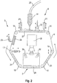
- the print head 3 is shown in greater detail in Fig. 2 .
- the print head 3 comprises an endless carrier film 4 that is guided to circulate along a closed path.
- the carrier film 4 is guided by a plurality of rollers, including deflection rollers 16, a tension roller 17 and an adjustable roller 18.
- a nozzle 19 is provided that is connected to a resin feeding hose 20. The nozzle 19 ejects a photopolymer resin onto the carrier film 4.
- the resin is ejected as a result of an overpressure (e.g., pressure beyond an acceptable threshold) in the hose 20 and the nozzle 19 when compared to the environment, wherein the overpressure may be created by mechanical or pneumatic systems to pump the viscous photopolymer resin from a storage tank towards the coating zone 6.
- an overpressure e.g., pressure beyond an acceptable threshold
- such coating mechanisms, including the storage tank, the hose 20 and the nozzle 19, may be heated in a controlled way.
- a coating blade 21 serves to define a material layer of a defined thickness on the carrier film 4.
- the coating blade 21 is adjustable in the height direction in order to adjust the desired layer thickness.
- a scraper 22 is provided to refresh or mix the material in the coating zone 6. In various embodiments, the scraper 22 may be heated in a controlled way.
- a support plate 27 is arranged at the back side of the carrier film 4 in the coating zone 6. The support plate 27 may function as a heating element, if needed.
- An optional de-coating system denoted by reference numeral 23 may operate to de-coat (e.g., remove material from) the carrier film 4 for various purposes during process cleaning or material exchange procedures.
- the de-coating system 23 may comprise a scraper blade, which is pressed against a support plate 26 with the moving carrier film 4 being in between.
- Heating elements may be provided for keeping or heating the material layer at an elevated temperature, including a pre-heating plate 24 and a post-heating plate 25.
- the function of said heating plates as being a pre- or post-heating plate may switch.
- the element 24 may operate as a pre-heating plate and the element 25 may operate as a post-heating plate; conversely, if the carrier film 4 were rotating in a clockwise motion, the element 25 may operate a pre-heating plate and the element 24 may operate a post-heating plate.
- the light engine 28 of the print head 3 is denoted by the reference numeral 28 and emits light into an exposure field 7.
- a guiding plate 29 is arranged that is at least partially transparent to the wavelength of the light emitted by the light engine 28.
- the guiding plate is arranged on the back side of the carrier film 4 and serves to guide the carrier film 4 so as to define a precise position of the carrier film 4 relative to the building platform 1 with a precisely defined gap being arranged between the carrier film 4 and the building platform 1.
- the transparent guiding plate 29 is heated by a contactless heating system comprising infrared lamps 30.
- the material management units may include a spray coating system 31, an inkjet system 32, a soldering system, a plasma coating system or a wiring system 33 and a multipurpose robotic arm 34. Each of these units may have its own linear encoder 11.
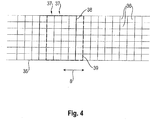
- Fig. 4 schematically illustrates the structuring of the pattern data in the form of a virtual grid 35 of pixels 36 that represent the pattern to be printed in a specific layer during the printing process.
- the length of the pattern along a direction 8 corresponds to the length of the component to be printed.
- the pattern may be divided into a plurality of pattern sections that may comprise one or more rows 37 of the pattern.
- a first pattern section is denoted by 38 and comprises five rows 37.
- a second pattern section is denoted by 39 and is offset by one row 37 relative to the first pattern section 38.
- further pattern sections that are each offset by one row of pixels.
- the feed rate of the sequence of pattern section is adapted to the velocity of the print head 3 as sensed by the linear encoder 11, in order to safeguard a precise printing process.
- the printing process can be physically scaled in terms of maximum building platform length extending along the displacement path 8. It can further be scaled in terms of building platform width by selecting a suitable width of the exposure field, e.g., the width of the light engine (such as the length of the laser scanning line or the length of the LED or micro LED array) or by using a plurality of light engines side by side.
- the process can also be scaled in terms of throughput or exposure speed, since the accuracy of the printing process is independent of the relative velocity of the print head and the building platform due to the position and/or velocity measuring system that controls the feeding rate of the pattern data feeder.
- Fig. 5 illustrates a flowchart 500 of an example method for 3D printing an object using a 3D printing system.
- the flowchart 500 is discussed in conjunction with the example structures described in the context of Figs. 1-4 . It is noted, however, that the operations of the flowchart 500 may be executed by structures and/or devices other than those shown in Figs. 1-4 .
- the operations of the flowchart 500 are by way of example only, and it is noted that various implementations may employ a greater or lesser number of operations than those shown in Fig. 5 .
- a photopolymer resin may be ejected onto a carrier film of a material transport unit to create one or more material layers of the photopolymer resin on the carrier film.
- the nozzle 19 may eject photopolymer resin onto the coating zone 6 on the carrier film 4. As noted herein, this may occur on a surface of the carrier film 4 adjacent to the support plate 27 and/or other convenient surfaces of the carrier film.
- the thickness of the one or more material layers may be maintained at a specified thickness.
- maintaining the thickness of the one or more material layers could involve removing at least a part of those material layers to level them.
- the coating blade 21, for instance may operate to maintain the material layers at a desired thickness, e.g., by removing and/or leveling the material layers.
- the one or more material layers may be mixed in a coating zone on the carrier film.
- the scraper 22 may operate to mix material layers on the coating zone 6 of the carrier film 4.
- the material transport unit may be driven to transport the one or more material layers toward an exposure field that is configured to expose light from a light source toward at least a portion of a building plane of a building platform.
- the carrier film 4 may be driven by a first drive mechanism, depending on embodiment, along the arrow 5 or the arrow 9 to transport the one or more material layers deposited on the coating zone 6 toward a building plane on the building platform 1 and/or toward the exposure field 7 associated with the light engine 28.
- other drive mechanisms may be used to drive the material layers toward an exposure field and/or a building plane as well.
- a position or velocity of the light engine may be sensed relative to the building platform.
- a sensor signal may be provided in response to the sensing of the position or velocity of the light engine.
- the linear encoder 11 may operate to sense position/velocity of the light engine 28 relative to the building platform 1.
- the linear encoder 11 may provide sensor signals to control units, which may reside internally and/or be coupled to the linear encoder 11.
- the linear encoder 11 may take optical measurements of the light engine 28 in order to derive position/velocity measurements.
- the linear encoder 11 may also be configured to sense optical marks, electromagnetic marks and/or magnetic marks.
- a control unit may adjust feeding rates of a pattern data feeder in response to the sensor signal.
- a control unit (possibly external to or residing within the linear encoder 11) may be configured to provide instructions to optimize movement of the carrier film 4, the light engine 28, the building platform 1, or some combination thereof to optimize their movement relative to one another. In some embodiments, this may involve minimizing relative movement and/or synchronizing their movement so that the carrier film 4, the light engine 28, and/or the building plane 1 are synchronized in position and/or velocity.
- the movement of the material transport unit, the light engine, and/or the building platform may be optimized in response to the instructions.
- the movement of the carrier film 4, the light engine 28, and/or the building platform 1 may be optimized (e.g., minimized, etc.) so that the carrier film 4, the light engine 28, and/or the building plane 1 are synchronized in position and/or velocity.
- the tension roller 17 and/or the adjustable roller 18 may operate, in response to the instructions, to modify positions/velocities of the carrier film.
- the print head 3 similarly may operate, in response to the instructions, to modify positions/velocities of the light engine 28.
- the motion of the tension roller 17 and/or the adjustable roller 18 is synchronized with the motion of the print head 3 to optimize movement between the carrier film 4 and the light engine 28 relative to the building platform 1.
- the carrier film may be guided to a specified position relative to the building platform to create a gap with a specified width between the carrier film and the building platform.
- the carrier film 4 may be guided to a specified position relative to the building platform to create a gap with a specified width between the carrier film 4 and the building platform 1. This gap may allow for 3D printing and/or selective curing (described in detail herein) between the carrier film 4 and the building platform 1.
- the one or material layers may be maintained at a specified temperature, e.g. by being heated within the exposure field.
- the pre-heating plate 24 if the carrier film 4 is moving along arrow 5 (or alternatively the element 25 if the carrier film is moving along arrow 9) may operate to heat the material layers before they are heated by the contactless heating system(s) 30 within the exposure field 7.
- At an operation 70 at least a portion of the material layers may be heated while on the building plane within the exposure field 7.
- the contactless heating system 30 may heat the material layers while they reside on the building plate 1 within the exposure field 7.
- pattern section data may be fed to the light engine at a feeding rate.
- a sequence of pattern sections may be emitted at the feeding rate during the relative movement of the light engine and the building platform along the displacement path.
- a pattern data feeder may feed pattern section data to the light engine 28 at a feeding rate.
- the feeding rate may be controlled by a control unit coupled to or internal to the linear encoder 11. This may occur along a displacement path (e.g., displacement path 8) or other path.
- light from the light engine may be exposed to at least a portion of the building plane of the building platform.
- the light engine 28 may operate to expose light (e.g., through the guiding plate 29) toward the building platform 1.
- light from the light engine 7 may operate to 3D print materials, even those with formulations with viscosities that were traditionally difficult to 3D print.
- the at least a portion of the material layers may be maintained at a specified temperature (possibly, but not necessarily the same as the specified temperature maintained before photo curing) after they are heated and/or cured. As noted herein, depending on direction the post-heating plate 25 or the element 24 may perform this operation.
Landscapes
- Engineering & Computer Science (AREA)
- Chemical & Material Sciences (AREA)
- Materials Engineering (AREA)
- Manufacturing & Machinery (AREA)
- Physics & Mathematics (AREA)
- Optics & Photonics (AREA)
- Mechanical Engineering (AREA)
- Health & Medical Sciences (AREA)
- Toxicology (AREA)
- General Physics & Mathematics (AREA)
- Plasma & Fusion (AREA)
Priority Applications (7)
| Application Number | Priority Date | Filing Date | Title |
|---|---|---|---|
| EP19020726.6A EP3842865A1 (fr) | 2019-12-23 | 2019-12-23 | Systèmes et procédés de fabrication additive à base de lithographie de structures tridimensionnelles (3d) |
| JP2022538780A JP2023508153A (ja) | 2019-12-23 | 2020-12-21 | リソグラフィに基づく3次元(3d)構造体の付加製造のためのシステム及び方法 |
| CA3162602A CA3162602A1 (fr) | 2019-12-23 | 2020-12-21 | Systemes et procedes pour des structures tridimensionnelles (3d) de fabrication additive basee sur la lithographie |
| AU2020414477A AU2020414477A1 (en) | 2019-12-23 | 2020-12-21 | Systems and methods for lithography-based additive manufacturing three-dimensional (3D) structures |
| KR1020227025417A KR20220119685A (ko) | 2019-12-23 | 2020-12-21 | 3차원(3d) 구조물들을 리소그래피-기반 적층 가공하기 위한 시스템들 및 방법들 |
| CN202080097375.8A CN115104065A (zh) | 2019-12-23 | 2020-12-21 | 用于基于光刻增材制造三维(3d)结构的系统和方法 |
| PCT/IB2020/062290 WO2021130657A1 (fr) | 2019-12-23 | 2020-12-21 | Systèmes et procédés pour des structures tridimensionnelles (3d) de fabrication additive basée sur la lithographie |
Applications Claiming Priority (1)
| Application Number | Priority Date | Filing Date | Title |
|---|---|---|---|
| EP19020726.6A EP3842865A1 (fr) | 2019-12-23 | 2019-12-23 | Systèmes et procédés de fabrication additive à base de lithographie de structures tridimensionnelles (3d) |
Publications (1)
| Publication Number | Publication Date |
|---|---|
| EP3842865A1 true EP3842865A1 (fr) | 2021-06-30 |
Family
ID=69063580
Family Applications (1)
| Application Number | Title | Priority Date | Filing Date |
|---|---|---|---|
| EP19020726.6A Pending EP3842865A1 (fr) | 2019-12-23 | 2019-12-23 | Systèmes et procédés de fabrication additive à base de lithographie de structures tridimensionnelles (3d) |
Country Status (7)
| Country | Link |
|---|---|
| EP (1) | EP3842865A1 (fr) |
| JP (1) | JP2023508153A (fr) |
| KR (1) | KR20220119685A (fr) |
| CN (1) | CN115104065A (fr) |
| AU (1) | AU2020414477A1 (fr) |
| CA (1) | CA3162602A1 (fr) |
| WO (1) | WO2021130657A1 (fr) |
Families Citing this family (10)
| Publication number | Priority date | Publication date | Assignee | Title |
|---|---|---|---|---|
| CN113681898B (zh) * | 2021-09-17 | 2023-03-21 | 珠海赛纳三维科技有限公司 | 三维物体打印方法、数据处理装置及计算机设备 |
| US11945166B2 (en) | 2021-10-28 | 2024-04-02 | Align Technology, Inc. | Methods for cleaning and post-curing additively manufactured objects |
| US20230264428A1 (en) | 2022-02-23 | 2023-08-24 | Align Technology, Inc. | Indirect temperature monitoring for additive manufacturing |
| US20240051246A1 (en) | 2022-08-15 | 2024-02-15 | Align Technology, Inc. | Methods for selective post-curing of additively manufactured objects |
| WO2024059749A2 (fr) | 2022-09-15 | 2024-03-21 | Align Technology, Inc. | Systèmes et procédés de modification de surfaces d'objets fabriqués de manière additive |
| WO2024064832A2 (fr) | 2022-09-22 | 2024-03-28 | Cubicure Gmbh | Plateformes de construction modulaires pour fabrication additive |
| US20240131795A1 (en) | 2022-10-20 | 2024-04-25 | Align Technology, Inc. | Systems and methods for generating directly manufacturable dental appliances |
| WO2024092007A1 (fr) | 2022-10-26 | 2024-05-02 | Align Technology, Inc. | Matériaux et objets fabriqués de manière additive avec des éléments à verrouillage mécanique |
| WO2024092097A1 (fr) | 2022-10-26 | 2024-05-02 | Align Technology, Inc. | Systèmes de fabrication additive à substrats fixes |
| US20240140043A1 (en) | 2022-11-01 | 2024-05-02 | Align Technology, Inc. | Prefabricated support structures and/or overlays for additive manufacturing |
Citations (12)
| Publication number | Priority date | Publication date | Assignee | Title |
|---|---|---|---|---|
| EP0557051A1 (fr) * | 1992-02-20 | 1993-08-25 | Teijin Seiki Company Limited | Procédé pour photomodelage |
| WO1998048997A1 (fr) * | 1997-04-28 | 1998-11-05 | 3D Systems, Inc. | Appareil et procede pour regler l'exposition d'un milieu solidifiable a une source de rayonnement pulse dans la construction d'un objet tridimensionnel |
| WO2010074566A1 (fr) * | 2008-12-22 | 2010-07-01 | Nederlandse Organisatie Voor Toegepast-Natuurwetenschappelijk Onderzoek Tno | Procédé et appareil pour la production par couches d'un objet en 3d |
| WO2012174332A1 (fr) * | 2011-06-15 | 2012-12-20 | Dsm Ip Assets Bv | Processus et appareil de fabrication d'additif à base de substrat |
| WO2016201309A1 (fr) * | 2015-06-10 | 2016-12-15 | Ipg Photonics Corporation | Fabrication additive à faisceaux multiples |
| US20170066185A1 (en) | 2015-09-09 | 2017-03-09 | Carbon3D, Inc. | Method and apparatus for three-dimensional fabrication |
| EP3319543A1 (fr) | 2015-07-07 | 2018-05-16 | Align Technology, Inc. | Matériaux dentaires utilisant des polymères thermodurcissables |
| WO2018109734A2 (fr) * | 2016-12-18 | 2018-06-21 | Csir | Appareil et procédé de fabrication additive |
| DE102018112381A1 (de) * | 2017-05-31 | 2018-12-06 | General Electric Company | Vorrichtung und Verfahren zur gleichzeitigen additiven und subtraktiven Echtzeitfertigung mit einem Mechanismus zur Wiedergewinnung ungenutzten Rohmaterials |
| EP3418033A1 (fr) | 2017-06-19 | 2018-12-26 | Cubicure GmbH | Procédé et dispositif de fabrication générative par lithographie de formes tridimensionnelles |
| WO2019213585A1 (fr) | 2018-05-04 | 2019-11-07 | Align Technology, Inc. | Composition durcissable destinée à être utilisée dans un procédé de photopolymérisation basé sur la lithographie à haute température et procédé de production de polymères réticulés à partir de celle-ci |
| WO2019213588A1 (fr) | 2018-05-04 | 2019-11-07 | Align Technology, Inc. | Monomères polymérisables et leur procédé de polymérisation |
-
2019
- 2019-12-23 EP EP19020726.6A patent/EP3842865A1/fr active Pending
-
2020
- 2020-12-21 JP JP2022538780A patent/JP2023508153A/ja active Pending
- 2020-12-21 WO PCT/IB2020/062290 patent/WO2021130657A1/fr active Application Filing
- 2020-12-21 AU AU2020414477A patent/AU2020414477A1/en active Pending
- 2020-12-21 KR KR1020227025417A patent/KR20220119685A/ko unknown
- 2020-12-21 CN CN202080097375.8A patent/CN115104065A/zh active Pending
- 2020-12-21 CA CA3162602A patent/CA3162602A1/fr active Pending
Patent Citations (12)
| Publication number | Priority date | Publication date | Assignee | Title |
|---|---|---|---|---|
| EP0557051A1 (fr) * | 1992-02-20 | 1993-08-25 | Teijin Seiki Company Limited | Procédé pour photomodelage |
| WO1998048997A1 (fr) * | 1997-04-28 | 1998-11-05 | 3D Systems, Inc. | Appareil et procede pour regler l'exposition d'un milieu solidifiable a une source de rayonnement pulse dans la construction d'un objet tridimensionnel |
| WO2010074566A1 (fr) * | 2008-12-22 | 2010-07-01 | Nederlandse Organisatie Voor Toegepast-Natuurwetenschappelijk Onderzoek Tno | Procédé et appareil pour la production par couches d'un objet en 3d |
| WO2012174332A1 (fr) * | 2011-06-15 | 2012-12-20 | Dsm Ip Assets Bv | Processus et appareil de fabrication d'additif à base de substrat |
| WO2016201309A1 (fr) * | 2015-06-10 | 2016-12-15 | Ipg Photonics Corporation | Fabrication additive à faisceaux multiples |
| EP3319543A1 (fr) | 2015-07-07 | 2018-05-16 | Align Technology, Inc. | Matériaux dentaires utilisant des polymères thermodurcissables |
| US20170066185A1 (en) | 2015-09-09 | 2017-03-09 | Carbon3D, Inc. | Method and apparatus for three-dimensional fabrication |
| WO2018109734A2 (fr) * | 2016-12-18 | 2018-06-21 | Csir | Appareil et procédé de fabrication additive |
| DE102018112381A1 (de) * | 2017-05-31 | 2018-12-06 | General Electric Company | Vorrichtung und Verfahren zur gleichzeitigen additiven und subtraktiven Echtzeitfertigung mit einem Mechanismus zur Wiedergewinnung ungenutzten Rohmaterials |
| EP3418033A1 (fr) | 2017-06-19 | 2018-12-26 | Cubicure GmbH | Procédé et dispositif de fabrication générative par lithographie de formes tridimensionnelles |
| WO2019213585A1 (fr) | 2018-05-04 | 2019-11-07 | Align Technology, Inc. | Composition durcissable destinée à être utilisée dans un procédé de photopolymérisation basé sur la lithographie à haute température et procédé de production de polymères réticulés à partir de celle-ci |
| WO2019213588A1 (fr) | 2018-05-04 | 2019-11-07 | Align Technology, Inc. | Monomères polymérisables et leur procédé de polymérisation |
Also Published As
| Publication number | Publication date |
|---|---|
| AU2020414477A1 (en) | 2022-06-30 |
| CA3162602A1 (fr) | 2021-07-01 |
| CN115104065A (zh) | 2022-09-23 |
| WO2021130657A1 (fr) | 2021-07-01 |
| JP2023508153A (ja) | 2023-03-01 |
| KR20220119685A (ko) | 2022-08-30 |
Similar Documents
| Publication | Publication Date | Title |
|---|---|---|
| US11904550B2 (en) | System for the lithography-based additive manufacturing of three-dimensional (3D) structures | |
| EP3842865A1 (fr) | Systèmes et procédés de fabrication additive à base de lithographie de structures tridimensionnelles (3d) | |
| US20230294354A1 (en) | Systems and methods for lithography-based additive manufacturing three-dimensional (3d) structures | |
| JP6640375B2 (ja) | 3d印刷デバイスを使用することにより物体を製造するための方法およびデバイス | |
| EP1946908B1 (fr) | Système d'imagerie solide avec suppression de l'excès de matériau de construction non durci | |
| EP1946910B1 (fr) | Assemblage d'imageur et procédé d'imagerie solide | |
| US7731887B2 (en) | Method for removing excess uncured build material in solid imaging | |
| CN110869189B (zh) | 用于基于光刻生成地制造三维成型体的方法和装置 | |
| US20240009932A1 (en) | Method and apparatus for layer thickness control in additive manufacturing | |
| EP3452266A2 (fr) | Systèmes d'exposition, systèmes d'impression, procédés de fabrication additive, compositions et leur utilisation | |
| US11845222B2 (en) | Increasing throughput in additive manufacturing using a rotating build platform | |
| US20210331413A1 (en) | Controlling energy source in three-dimensional printing | |
| JP7199456B2 (ja) | 3次元物体を製造するためのステレオリソグラフィ方法および機械 | |
| CN216506784U (zh) | 3d打印设备、系统及控制装置 | |
| CN110856978B (zh) | 3d打印系统及3d打印方法 | |
| CN114147965A (zh) | 3d打印方法、设备、系统及控制方法和装置 |
Legal Events
| Date | Code | Title | Description |
|---|---|---|---|
| PUAI | Public reference made under article 153(3) epc to a published international application that has entered the european phase |
Free format text: ORIGINAL CODE: 0009012 |
|
| STAA | Information on the status of an ep patent application or granted ep patent |
Free format text: STATUS: THE APPLICATION HAS BEEN PUBLISHED |
|
| AK | Designated contracting states |
Kind code of ref document: A1 Designated state(s): AL AT BE BG CH CY CZ DE DK EE ES FI FR GB GR HR HU IE IS IT LI LT LU LV MC MK MT NL NO PL PT RO RS SE SI SK SM TR |
|
| STAA | Information on the status of an ep patent application or granted ep patent |
Free format text: STATUS: REQUEST FOR EXAMINATION WAS MADE |
|
| 17P | Request for examination filed |
Effective date: 20211228 |
|
| RBV | Designated contracting states (corrected) |
Designated state(s): AL AT BE BG CH CY CZ DE DK EE ES FI FR GB GR HR HU IE IS IT LI LT LU LV MC MK MT NL NO PL PT RO RS SE SI SK SM TR |
|
| P01 | Opt-out of the competence of the unified patent court (upc) registered |
Effective date: 20230530 |