EP3842833A1 - Radar signal processing method and device - Google Patents
Radar signal processing method and device Download PDFInfo
- Publication number
- EP3842833A1 EP3842833A1 EP19876754.3A EP19876754A EP3842833A1 EP 3842833 A1 EP3842833 A1 EP 3842833A1 EP 19876754 A EP19876754 A EP 19876754A EP 3842833 A1 EP3842833 A1 EP 3842833A1
- Authority
- EP
- European Patent Office
- Prior art keywords
- radar signal
- frequency
- signal
- radar
- reflected
- Prior art date
- Legal status (The legal status is an assumption and is not a legal conclusion. Google has not performed a legal analysis and makes no representation as to the accuracy of the status listed.)
- Pending
Links
Images





Classifications
-
- G—PHYSICS
- G01—MEASURING; TESTING
- G01S—RADIO DIRECTION-FINDING; RADIO NAVIGATION; DETERMINING DISTANCE OR VELOCITY BY USE OF RADIO WAVES; LOCATING OR PRESENCE-DETECTING BY USE OF THE REFLECTION OR RERADIATION OF RADIO WAVES; ANALOGOUS ARRANGEMENTS USING OTHER WAVES
- G01S13/00—Systems using the reflection or reradiation of radio waves, e.g. radar systems; Analogous systems using reflection or reradiation of waves whose nature or wavelength is irrelevant or unspecified
- G01S13/02—Systems using reflection of radio waves, e.g. primary radar systems; Analogous systems
-
- G—PHYSICS
- G01—MEASURING; TESTING
- G01S—RADIO DIRECTION-FINDING; RADIO NAVIGATION; DETERMINING DISTANCE OR VELOCITY BY USE OF RADIO WAVES; LOCATING OR PRESENCE-DETECTING BY USE OF THE REFLECTION OR RERADIATION OF RADIO WAVES; ANALOGOUS ARRANGEMENTS USING OTHER WAVES
- G01S13/00—Systems using the reflection or reradiation of radio waves, e.g. radar systems; Analogous systems using reflection or reradiation of waves whose nature or wavelength is irrelevant or unspecified
- G01S13/02—Systems using reflection of radio waves, e.g. primary radar systems; Analogous systems
- G01S13/06—Systems determining position data of a target
- G01S13/08—Systems for measuring distance only
- G01S13/32—Systems for measuring distance only using transmission of continuous waves, whether amplitude-, frequency-, or phase-modulated, or unmodulated
- G01S13/34—Systems for measuring distance only using transmission of continuous waves, whether amplitude-, frequency-, or phase-modulated, or unmodulated using transmission of continuous, frequency-modulated waves while heterodyning the received signal, or a signal derived therefrom, with a locally-generated signal related to the contemporaneously transmitted signal
-
- G—PHYSICS
- G01—MEASURING; TESTING
- G01S—RADIO DIRECTION-FINDING; RADIO NAVIGATION; DETERMINING DISTANCE OR VELOCITY BY USE OF RADIO WAVES; LOCATING OR PRESENCE-DETECTING BY USE OF THE REFLECTION OR RERADIATION OF RADIO WAVES; ANALOGOUS ARRANGEMENTS USING OTHER WAVES
- G01S13/00—Systems using the reflection or reradiation of radio waves, e.g. radar systems; Analogous systems using reflection or reradiation of waves whose nature or wavelength is irrelevant or unspecified
- G01S13/02—Systems using reflection of radio waves, e.g. primary radar systems; Analogous systems
- G01S13/06—Systems determining position data of a target
- G01S13/08—Systems for measuring distance only
- G01S13/32—Systems for measuring distance only using transmission of continuous waves, whether amplitude-, frequency-, or phase-modulated, or unmodulated
-
- G—PHYSICS
- G01—MEASURING; TESTING
- G01S—RADIO DIRECTION-FINDING; RADIO NAVIGATION; DETERMINING DISTANCE OR VELOCITY BY USE OF RADIO WAVES; LOCATING OR PRESENCE-DETECTING BY USE OF THE REFLECTION OR RERADIATION OF RADIO WAVES; ANALOGOUS ARRANGEMENTS USING OTHER WAVES
- G01S13/00—Systems using the reflection or reradiation of radio waves, e.g. radar systems; Analogous systems using reflection or reradiation of waves whose nature or wavelength is irrelevant or unspecified
- G01S13/02—Systems using reflection of radio waves, e.g. primary radar systems; Analogous systems
- G01S13/50—Systems of measurement based on relative movement of target
- G01S13/52—Discriminating between fixed and moving objects or between objects moving at different speeds
- G01S13/536—Discriminating between fixed and moving objects or between objects moving at different speeds using transmission of continuous unmodulated waves, amplitude-, frequency-, or phase-modulated waves
-
- G—PHYSICS
- G01—MEASURING; TESTING
- G01S—RADIO DIRECTION-FINDING; RADIO NAVIGATION; DETERMINING DISTANCE OR VELOCITY BY USE OF RADIO WAVES; LOCATING OR PRESENCE-DETECTING BY USE OF THE REFLECTION OR RERADIATION OF RADIO WAVES; ANALOGOUS ARRANGEMENTS USING OTHER WAVES
- G01S13/00—Systems using the reflection or reradiation of radio waves, e.g. radar systems; Analogous systems using reflection or reradiation of waves whose nature or wavelength is irrelevant or unspecified
- G01S13/02—Systems using reflection of radio waves, e.g. primary radar systems; Analogous systems
- G01S13/50—Systems of measurement based on relative movement of target
- G01S13/58—Velocity or trajectory determination systems; Sense-of-movement determination systems
-
- G—PHYSICS
- G01—MEASURING; TESTING
- G01S—RADIO DIRECTION-FINDING; RADIO NAVIGATION; DETERMINING DISTANCE OR VELOCITY BY USE OF RADIO WAVES; LOCATING OR PRESENCE-DETECTING BY USE OF THE REFLECTION OR RERADIATION OF RADIO WAVES; ANALOGOUS ARRANGEMENTS USING OTHER WAVES
- G01S13/00—Systems using the reflection or reradiation of radio waves, e.g. radar systems; Analogous systems using reflection or reradiation of waves whose nature or wavelength is irrelevant or unspecified
- G01S13/02—Systems using reflection of radio waves, e.g. primary radar systems; Analogous systems
- G01S13/50—Systems of measurement based on relative movement of target
- G01S13/58—Velocity or trajectory determination systems; Sense-of-movement determination systems
- G01S13/583—Velocity or trajectory determination systems; Sense-of-movement determination systems using transmission of continuous unmodulated waves, amplitude-, frequency-, or phase-modulated waves and based upon the Doppler effect resulting from movement of targets
- G01S13/584—Velocity or trajectory determination systems; Sense-of-movement determination systems using transmission of continuous unmodulated waves, amplitude-, frequency-, or phase-modulated waves and based upon the Doppler effect resulting from movement of targets adapted for simultaneous range and velocity measurements
-
- G—PHYSICS
- G01—MEASURING; TESTING
- G01S—RADIO DIRECTION-FINDING; RADIO NAVIGATION; DETERMINING DISTANCE OR VELOCITY BY USE OF RADIO WAVES; LOCATING OR PRESENCE-DETECTING BY USE OF THE REFLECTION OR RERADIATION OF RADIO WAVES; ANALOGOUS ARRANGEMENTS USING OTHER WAVES
- G01S7/00—Details of systems according to groups G01S13/00, G01S15/00, G01S17/00
- G01S7/02—Details of systems according to groups G01S13/00, G01S15/00, G01S17/00 of systems according to group G01S13/00
- G01S7/35—Details of non-pulse systems
- G01S7/352—Receivers
-
- Y—GENERAL TAGGING OF NEW TECHNOLOGICAL DEVELOPMENTS; GENERAL TAGGING OF CROSS-SECTIONAL TECHNOLOGIES SPANNING OVER SEVERAL SECTIONS OF THE IPC; TECHNICAL SUBJECTS COVERED BY FORMER USPC CROSS-REFERENCE ART COLLECTIONS [XRACs] AND DIGESTS
- Y02—TECHNOLOGIES OR APPLICATIONS FOR MITIGATION OR ADAPTATION AGAINST CLIMATE CHANGE
- Y02A—TECHNOLOGIES FOR ADAPTATION TO CLIMATE CHANGE
- Y02A90/00—Technologies having an indirect contribution to adaptation to climate change
- Y02A90/10—Information and communication technologies [ICT] supporting adaptation to climate change, e.g. for weather forecasting or climate simulation
Definitions
- This application relates to the field of microwave radar, and in particular, to a millimeter-wave radar signal processing method and apparatus.
- ADAS advanced driving assistant system
- various sensors installed on the vehicle are used to sense a surrounding environment at any time, collect data, identify, detect, and track static and moving objects, and perform systematic calculation and analysis with reference to navigation map data, so that a driver can be aware of a possible danger in advance, thereby effectively improving comfort and safety of driving.
- Embodiments of this application provide a radar signal processing method and apparatus, to increase frequency sweep bandwidth of radar.
- a radar signal processing method is provided, and is applied to a first apparatus, and the method includes: transmitting a first radar signal on a first frequency band; transmitting a second radar signal on a second frequency band; receiving a first reflected signal and a second reflected signal, where the first reflected signal is an electromagnetic wave obtained after the first radar signal is reflected by a target object, and the second reflected signal is an electromagnetic wave obtained after the second radar signal is reflected by the target object; and obtaining at least one of range information, velocity information, and angle information of the target object.
- two radar signals are transmitted on different frequency bands, and reflected signals of the two radar signals are correspondingly received, to obtain the at least one of the range information, the velocity information, and the angle information of the target object.
- Radar signals can be transmitted by using inconsecutive frequency domain resources, and therefore frequency sweep bandwidth of radar is expanded. In this way, range resolution of the radar is improved.
- the obtaining at least one of range information, velocity information, and angle information of the target object includes: obtaining the at least one of the range information, the velocity information, and the angle information based on the first radar signal and the first reflected signal; or obtaining the at least one of the range information, the velocity information, and the angle information based on the second radar signal and the second reflected signal; or obtaining the at least one of the range information, the velocity information, and the angle information based on the first radar signal, the first reflected signal, the second radar signal, and the second reflected signal.
- the at least one of the range information, the velocity information, and the angle information of the target object may be obtained based on the radar signal and the corresponding reflected signal.
- the first radar signal and the second radar signal are transmitted in a first time unit, duration of the first radar signal is the same as duration of the second radar signal, and a length of the first time unit is equal to the duration.
- the duration of the first radar signal may be the same as the duration of the second radar signal.
- the duration may also be referred to as a frequency sweep time.
- the duration or the frequency sweep time is duration in which a frequency of a radar signal linearly increases from an initial frequency to a maximum frequency. For example, for a sawtooth wave, the duration may be duration of one transmission period, and for a triangular wave, the duration may be understood as duration of half a transmission period.
- the first frequency band and the second frequency band do not completely overlap in frequency domain.
- the first frequency band and the second frequency band may partially overlap in frequency domain.
- At least one of the first radar signal and the second radar signal is a linear frequency modulated continuous wave
- the linear frequency modulated continuous wave is an electromagnetic wave whose frequency linearly increases or decreases with time.
- the first radar signal or the second radar signal may be a sawtooth wave, or the first radar signal or the second radar signal is half a triangular wave.
- frequency variations of the first radar signal and the second radar signal in a unit time are opposites.
- expression may be as follows: A slope of a frequency of the first radar signal and a slope of a frequency of the second radar signal are opposites.
- frequency variations of the first radar signal and the second radar signal in a unit time are opposite in sign.
- expression may be as follows: A slope of a frequency of the first radar signal and a slope of a frequency of the second radar signal are opposite in sign.
- expression may be as follows: A frequency of the first radar signal linearly increases with time in a unit time, and a frequency of the second radar signal linearly decreases with time in the unit time; or a frequency of the first radar signal linearly decreases with time in a unit time, and a frequency of the second radar signal linearly increases with time in the unit time. In this case, time consumed for measuring the range information of the target object or the velocity information of the target object is reduced by half.
- a frequency of the first radar signal and a frequency of the second radar signal increase with time in a unit time; or a frequency of the first radar signal and a frequency of the second radar signal decrease with time in a unit time.
- expression may be as follows: A sign of a slope of a frequency of the first radar signal is the same as a sign of a slope of a frequency of the second radar signal. That is, the frequency of the first radar signal and the frequency of the second radar signal may be increased or decreased at the same time.
- frequency variations of the first radar signal and the second radar signal in the unit time are the same.
- expression may be as follows:
- the slope of the frequency of the first radar signal is the same as the slope of the frequency of the second radar signal.
- expression may be as follows: In the unit time, an absolute value of a variation by which the frequency of the first radar signal changes with time is the same as an absolute value of a variation by which the frequency of the second radar signal changes with time. In other words, the absolute value of the variation of the frequency of the first radar signal may be the same as the absolute value of the variation of the frequency of the second radar signal.
- a radar signal processing apparatus includes: a transmitting unit, configured to transmit a first radar signal on a first frequency band, where the transmitting unit is further configured to transmit a second radar signal on a second frequency band; a receiving unit, configured to receive a first reflected signal and a second reflected signal, where the first reflected signal is an electromagnetic wave obtained after the first radar signal is reflected by a target object, and the second reflected signal is an electromagnetic wave obtained after the second radar signal is reflected by the target object; and an obtaining unit, configured to obtain at least one of range information, velocity information, and angle information of the target object.
- the obtaining unit is specifically configured to: obtain the at least one of the range information, the velocity information, and the angle information based on the first radar signal and the first reflected signal; or obtain the at least one of the range information, the velocity information, and the angle information based on the second radar signal and the second reflected signal; or obtain the at least one of the range information, the velocity information, and the angle information based on the first radar signal, the first reflected signal, the second radar signal, and the second reflected signal.
- the first radar signal and the second radar signal are transmitted in a first time unit, duration of the first radar signal is the same as duration of the second radar signal, and a length of the first time unit is equal to the duration.
- the first frequency band and the second frequency band do not completely overlap in frequency domain.
- At least one of the first radar signal and the second radar signal is a linear frequency modulated continuous wave
- the linear frequency modulated continuous wave is an electromagnetic wave whose frequency linearly increases or decreases with time.
- the first radar signal or the second radar signal may be a sawtooth wave, or the first radar signal or the second radar signal is half a triangular wave.
- frequency variations of the first radar signal and the second radar signal in a unit time are opposites.
- expression may be as follows: A slope of a frequency of the first radar signal and a slope of a frequency of the second radar signal are opposites.
- frequency variations of the first radar signal and the second radar signal in a unit time are opposite in sign.
- expression may be as follows: A slope of a frequency of the first radar signal and a slope of a frequency of the second radar signal are opposite in sign.
- expression may be as follows: A frequency of the first radar signal linearly increases with time in a unit time, and a frequency of the second radar signal linearly decreases with time in the unit time; or a frequency of the first radar signal linearly decreases with time in a unit time, and a frequency of the second radar signal linearly increases with time in the unit time. In this case, time consumed for measuring the range information of the target object or the velocity information of the target object is reduced by half.
- a frequency of the first radar signal and a frequency of the second radar signal increase with time in a unit time; or a frequency of the first radar signal and a frequency of the second radar signal decrease with time in a unit time.
- expression may be as follows: A sign of a slope of a frequency of the first radar signal is the same as a sign of a slope of a frequency of the second radar signal. That is, the frequency of the first radar signal and the frequency of the second radar signal may be increased or decreased at the same time.
- frequency variations of the first radar signal and the second radar signal in the unit time are the same.
- expression may be as follows:
- the slope of the frequency of the first radar signal is the same as the slope of the frequency of the second radar signal.
- expression may be as follows: In the unit time, an absolute value of a variation by which the frequency of the first radar signal changes with time is the same as an absolute value of a variation by which the frequency of the second radar signal changes with time. In other words, the absolute value of the variation of the frequency of the first radar signal may be the same as the absolute value of the variation of the frequency of the second radar signal.
- a radar signal processing apparatus is provided, and is applied to the radar signal processing method according to the first aspect and the possible implementations of the first aspect.
- a storage medium stores a computer program, and when the computer program is executed by a processor, the radar signal processing method according to the first aspect and the possible implementations of the first aspect is implemented.
- a radar signal processing apparatus includes a processor and a memory.
- the memory is configured to store a program, and the processor invokes the program stored in the memory, to perform the radar signal processing method according to the first aspect and the possible implementations of the first aspect.
- an embodiment of this application provides a computer program product.
- a radar signal processing apparatus is enabled to perform the radar signal processing method according to the first aspect and the possible implementations of the first aspect.
- an embodiment of this application provides a chip system, including a processor, configured to support a radar signal processing apparatus in performing the radar signal processing method according to the first aspect and the possible implementations of the first aspect.
- Radar in the embodiments of this application may be applied to vehicle-to-everything (vehicle-to-everything, V2X), vehicle-to-vehicle (vehicle-to-vehicle, V2V) communication, vehicle-to-infrastructure (vehicle-to-infrastructure, V2I) communication, vehicle-to-pedestrian (vehicle-to-pedestrian, V2P) communication, and the like.
- V2X vehicle-to-everything
- V2V vehicle-to-everything
- V2V vehicle-to-vehicle
- V2V vehicle-to-vehicle
- V2I vehicle-to-infrastructure
- V2P vehicle-to-pedestrian
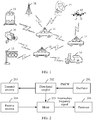
- the radar in the embodiments of this application may be installed on a motor vehicle 11, an unmanned aerial vehicle 12, a railway vehicle 13, a bicycle 14, a signal light 15, a velocity measurement apparatus 16, a radar station 17, a base station 18, or the like.
- a position at which the radar is installed and a specific field to which the radar is applied are not limited in this application.
- the radar in the embodiments of this application may also be referred to as a detector or a detection apparatus.
- a working principle of the radar is to detect a corresponding target object by transmitting a signal (or referred to as a detection signal) and receiving a reflected signal obtained after reflection by the target object.
- the signal may be a radio signal or an electromagnetic wave signal.
- the signals may be collectively referred to as a radar signal.
- the radar signal is periodically transmitted.
- duration of a complete sawtooth waveform may be understood as a transmission period of a sawtooth wave radar signal.
- duration of a complete triangular waveform may be understood as a transmission period of a triangular wave radar signal.
- the radar in the embodiments of this application may be applied to radar velocity measurement, ranging, angle measurement, and the like between vehicles, between a vehicle and an unmanned aerial vehicle, and between other apparatuses.
- the radar may be applied to adaptive cruise control (adaptive cruise control, ACC), autonomous emergency braking (autonomous emergency braking, AEB), lane change assist (lane change assist, LCA), blind spot monitoring (blind spot monitoring, BSM), parking assistance (parking assistance, PA), and pedestrian detection (pedestrian detection, PD).
- adaptive cruise control adaptive cruise control
- ACC autonomous cruise control
- AEB autonomous emergency braking
- lane change assist lane change assist
- blind spot monitoring blind spot monitoring
- BSM parking assistance
- PA pedestrian detection
- PD pedestrian detection
- the radar in the embodiments of this application may be millimeter-wave (millimeter wave, mmWave) radar, micrometer-wave radar, or the like.
- An attribute of an electromagnetic wave transmitted by the radar is not limited in this application.
- a millimeter wave refers to an electromagnetic wave with a wavelength of 1 mm to 10 mm, and corresponds to a frequency range of 30 GHz to 300 GHz.
- Millimeter wave-related features are quite suitable for application to the vehicle-mounted field.
- High bandwidth means abundant frequency domain resources and a low antenna side lobe, thereby facilitating imaging or quasi-imaging.
- a small wavelength means a reduced size of a radar device and a reduced antenna diameter, and therefore a weight is reduced.
- a narrow beam means that in the case of a same antenna size, a millimeter-wave beam is much narrower than a micrometer-wave beam, and therefore there is high radar resolution. Strong penetration means that compared with laser radar and an optical system, the millimeter-wave radar has a better capability of penetrating smoke, dust, and fog, and can work around the clock.
- an embodiment of this application provides radar.
- the radar includes an oscillator 201, a directional coupler 202, a transmit antenna 203, a receive antenna 204, a mixer 205, and a processor 206.
- oscillator 201 oscillator 201
- directional coupler 202 transmit antenna 203
- receive antenna 204 receive antenna 204
- mixer 205 mixer
- processor 206 processor
- the oscillator 201 generates a frequency modulated continuous wave (frequency modulated continuous wave, FMCW), and outputs the frequency modulated continuous wave to the directional coupler 202.
- FMCW frequency modulated continuous wave
- the frequency modulated continuous wave may be a linear frequency modulated continuous wave.
- the linear frequency modulated continuous wave is an electromagnetic wave whose frequency linearly increases or decreases with time. That is, in a time unit, the frequency of the frequency modulated continuous wave is in a linear relationship with time.
- absolute values of frequency variations of the frequency modulated continuous wave are the same (for a sawtooth wave, frequency variations are the same; and for a triangular wave, absolute values of frequency variations of a rising edge and a falling edge are the same).
- a slope of the frequency of the frequency modulated continuous wave is a slope of the linear relationship between the frequency of the frequency modulated continuous wave and time (for details, refer to FIG. 4 ).
- a sign of the slope is used to indicate whether the slope is a positive slope or a negative slope.
- the frequency linearly increases with time there is a rising edge, and the sign of the slope is positive.
- the frequency linearly decreases with time there is a falling edge, and the sign of the slope is negative.
- a linear frequency modulated continuous wave is used for description, but there is no limitation that the frequency modulated continuous wave needs to be a linear frequency modulated continuous wave.
- the directional coupler 202 outputs the frequency modulated continuous wave to the mixer 205 as a local-frequency signal, and outputs the frequency modulated continuous wave to the transmit antenna 203, and the transmit antenna 203 transmits the frequency modulated continuous wave.
- a reflected wave of the frequency modulated continuous wave is obtained after the frequency modulated continuous wave is reflected by a target object.
- the receive antenna 204 receives the reflected wave of the frequency modulated continuous wave, and then outputs the reflected wave to the mixer 205.
- the mixer 205 mixes the frequency modulated continuous wave and the reflected wave of the frequency modulated continuous wave to obtain an intermediate frequency (intermediate frequency, IF) signal.
- the intermediate frequency signal is a signal formed by a difference between frequencies of the frequency modulated continuous wave and the reflected wave of the frequency modulated continuous wave at a same moment. That is, a frequency of the intermediate frequency signal is the difference between the frequencies of the frequency modulated continuous wave and the reflected wave of the frequency modulated continuous wave at the same moment.
- the mixer 205 filters, by using a low-pass filter, the intermediate frequency signal obtained through mixing, and then amplifies and outputs the intermediate frequency signal to the processor 206.
- the processor 206 processes the intermediate frequency signal (for example, performs fast Fourier transformation and spectrum analysis on the intermediate frequency signal), to obtain at least one of range information, velocity information, and angle information of the target object.
- the range information, the velocity information, and the angle information of the target object, or a range, a velocity, and an angle of the target object, or a relative range, a relative velocity, and a relative angle of the target object are all relative to the radar that transmits the frequency modulated continuous wave.
- a specific name is not limited in this application.
- the processor 206 may send the at least one of the range information, the velocity information, and the angle information of the target object to a controller on the vehicle to control the vehicle.
- a waveform of the frequency modulated continuous wave is usually a sawtooth wave or a triangular wave.
- the following describes a working principle of the radar in detail by using an example in which the frequency modulated continuous wave is a triangular wave.
- FIG. 3 is a schematic diagram of a time amplitude of a frequency modulated continuous wave in a triangular wave form.
- a frequency of the frequency modulated continuous wave gradually increases with time in a time unit [0, T /2], and an amplitude of the frequency modulated continuous wave remains unchanged, where T is a period of the triangular wave.
- FIG. 4 is a schematic diagram of a time frequency of a frequency modulated continuous wave in a triangular wave form.
- a frequency of the frequency modulated continuous wave linearly increases with time by ⁇ F in a time unit [0, T /2], and the frequency of the frequency modulated continuous wave linearly decreases with time by ⁇ F in a time unit [ T /2, T ], where ⁇ F is a maximum variation range of the frequency of the frequency modulated continuous wave.
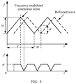
- the frequency modulated continuous wave and the reflected wave of the frequency modulated continuous wave are of a same shape, but there is a delay ⁇ t.
- T is the period of the triangular wave
- ⁇ F is the maximum variation range of the frequency modulated continuous wave.
- the range of the target object may be obtained by determining the frequency IF of the intermediate frequency signal.
- the frequency of the reflected wave of the frequency modulated continuous wave includes a Doppler frequency shift f d caused by relative motion of the target object.
- IF is a frequency of an intermediate frequency signal obtained when the target object is relatively static relative to the radar
- f is a center frequency of the frequency modulated continuous wave
- v is the velocity of the target object.
- the range information or the velocity information of the target object may be obtained by detecting the frequency f b + of the intermediate frequency signal of the rising edge of the triangular wave and the frequency f b- of the intermediate frequency signal of the falling edge of the triangular wave.
- the frequency modulated continuous wave is a sawtooth wave.
- a ranging principle of a sawtooth wave is similar to that of a triangular wave. As shown in FIG. 7 , there is a delay ⁇ between the frequency modulated continuous wave and the reflected wave of the frequency mo the second time undulated continuous wave, and a period of the sawtooth wave is T c .
- the relative range between the target object and the radar may be obtained by detecting the phase of the intermediate frequency signal.
- the radar transmits two frequency modulated continuous waves at a time interval T c , and receives reflected waves of the two frequency modulated continuous waves, to obtain two intermediate frequency signals.
- An angle measurement principle of the radar is also an extension of the ranging principle.
- the radar may include a first receive antenna 91 and a second receive antenna 92.
- a range between the two receive antennas is l .
- the reflected wave of the frequency modulated continuous wave arrives at the two receive antennas at different ranges.
- the range l between the two receive antennas is far less than the range between the target object and the radar. Therefore, directions of the reflected waves received by the two receive antennas may be approximately parallel, and two intermediate frequency signals may be obtained. It is obtained, based on the ranging principle, that phases of the two intermediate frequency signals are different, and a transmission angle may be deduced based on a difference between the phases of the two intermediate frequency signals.
- two frequency modulated continuous waves may be transmitted on different frequency bands by using same radar, reflected waves of the two frequency modulated continuous waves are correspondingly received, and intermediate frequency signals corresponding to the two frequency modulated continuous waves are obtained by using the method described above, to obtain at least one of range information, velocity information, and angle information of a target object.
- a frequency band in the embodiments of this application may be replaced with a frequency band. If two frequency bands are the same, it indicates that bandwidth, a minimum frequency, and a maximum frequency of the two frequency bands are the same.
- An embodiment of this application provides a radar signal processing method.
- the method is applied to a first apparatus.
- the first apparatus may be the radar described above or another apparatus with a control function, and the apparatus may be independent of or integrated into radar.
- the radar signal processing method includes the following steps.
- the first radar signal may be a first frequency modulated continuous wave.
- an initial frequency of the first radar signal is a minimum frequency of the first frequency band. In this design, transmit power of the first radar signal increases with time.
- an initial frequency of the first radar signal is a maximum frequency of the first frequency band. In this design, transmit power of the first radar signal decreases with time.
- the transmitting a first radar signal is transmitting the first radar signal in a first time unit.
- an initial moment for transmitting the first radar signal is a start moment of the first time unit.
- the second radar signal is a second frequency modulated continuous wave.
- an initial frequency of the second radar signal is a minimum frequency of the second frequency band. In this design, transmit power of the second radar signal increases with time.
- an initial frequency of the second radar signal is a maximum frequency of the second frequency band. In this design, transmit power of the second radar signal decreases with time.
- the transmitting a second radar signal is transmitting the second radar signal in the first time unit.
- an initial moment for transmitting the second radar signal is the start moment of the first time unit.
- the first frequency band and the second frequency band may not completely overlap in frequency domain, as shown in FIG. 11 .
- that the first frequency band and the second frequency band do not completely overlap means that the first frequency band is different from the second frequency band, and any one of the frequency bands is not included in the other frequency band.
- the first frequency band and the second frequency band do not overlap at all in frequency domain.
- the first radar signal and the second radar signal are transmitted in a first time unit T c 1
- duration of the first radar signal may be the same as duration of the second radar signal
- a length of the first time unit T c 1 is equal to the duration.
- the first time unit is a frequency sweep time of the first radar signal and the second radar signal.
- the first time unit may alternatively be understood as a "frequency sweep period", namely, a time unit in which both the first radar signal and the second radar signal complete frequency sweep. Further, the first time unit may be understood as each frequency sweep period.
- duration of the first radar signal may be different from duration of the second radar signal.
- the first radar signal is transmitted in a second time unit T c 2 , and a length of the second time unit T c 2 is equal to the duration of the first radar signal; and the second radar signal is transmitted in a third time unit T c 3 , and a length of the third time unit T c 3 is equal to the duration of the second radar signal, where T c 2 ⁇ T c 3 .
- the length of the first time unit T c 1 is greater than or equal to the length of the second time unit T c 2 , and is greater than or equal to the length of the third time unit T c 3 .
- the duration may also be referred to as a frequency sweep time or the like.
- a specific name is not limited in this embodiment of this application.
- a linear frequency modulated continuous wave is used as an example.
- a signal is transmitted from an initial frequency, and the initial frequency linearly increases to a maximum frequency in the transmission period (or linearly decreases to a minimum frequency in the transmission period) after specific duration.
- the duration may be referred to as duration a frequency sweep time of the linear frequency modulated continuous wave.
- the duration or the frequency sweep time may be one transmission period or half a transmission period.
- the duration or the frequency sweep time may be a time length or a quantity of symbols of one period; and for a triangular wave, the duration or the frequency sweep time may be half a time length or half a quantity of symbols of one period, namely, half a period.
- the unit time may be the first time unit, or may be any time period that is used as a calculation unit and that is in the first time unit, for example, one symbol, a plurality of symbols, one slot (slot), or one subframe.
- the unit time is not specifically limited in this embodiment of this application provided that a change relationship between a frequency of a radar signal or a frequency modulated continuous wave and time is clearly described.
- a sign of a slope of a frequency of the first radar signal is the same as a sign of a slope of a frequency of the second radar signal.
- the slope herein may be described as a variation of a frequency of a linear frequency modulated continuous wave in a unit time.
- frequencies of the first radar signal and the second radar signal increase with time in a unit time, or frequencies of the first radar signal and the second radar signal decrease with time in a unit time.
- frequencies of the first radar signal and the second radar signal increase with time in a unit time, or frequencies of the first radar signal and the second radar signal decrease with time in a unit time.
- FIG. 11 to FIG. 13 in a unit time, the frequency of the first radar signal and the frequency of the second radar signal linearly increase with time, and a frequency variation is a positive value.
- the frequency of the first radar signal and the frequency of the second radar signal decrease linearly with time, and a frequency variation is a negative value.
- an absolute value of a slope of a frequency of the first radar signal is the same as an absolute value of a slope of a frequency of the second radar signal.
- an absolute value of a frequency variation of the first radar signal is the same as an absolute value of a frequency variation of the second radar signal.
- the first radar signal and the second radar signal are transmitted by using the start moment of the first time unit as the initial moment, and the frequencies of the first radar signal and the second radar signal change by a same frequency variation in a unit time. It may be understood that the first radar signal and the second radar signal are respectively transmitted on the first frequency band and the second frequency band, but have a same waveform in the first time unit. Further, the duration of the first radar signal is the same as the duration of the second radar signal (both the duration of the first radar signal and the duration of the second radar signal are the length of the first time unit). In this case, the first radar signal and the second radar signal may be periodically transmitted on the respective frequency bands by using the length of the first time unit as a period.
- the slope of the frequency of the first radar signal is the same as the slope of the frequency of the second radar signal.
- the frequency variations of the first radar signal and the second radar signal in the unit time are the same.
- both the slope of the frequency of the first radar signal and the slope of the frequency of the second radar signal are 1.
- the slope of the frequency of the first radar signal and the slope of the frequency of the second radar signal are opposite in sign.
- the frequency variations of the first radar signal and the second radar signal in the unit time are opposites.
- the frequency of the first radar signal linearly increases with time, and the frequency of the second radar signal linearly decreases with time.
- a sign of the slope of the frequency of the first radar signal is positive, and a sign of the slope of the frequency of the second radar signal is negative.
- the frequency of the first radar signal linearly decreases with time, and the frequency of the second radar signal linearly increases with time.
- a sign of the slope of the frequency of the first radar signal is negative, and a sign of the slope of the frequency of the second radar signal is positive.
- the frequency of the first radar signal linearly increases with time, and the frequency of the second radar signal linearly decreases with time; and in a current time unit, the frequency of the first radar signal linearly decreases with time, and the frequency of the second radar signal linearly increases with time.
- the frequency of the first radar signal linearly decreases with time, and the frequency of the second radar signal linearly increases with time.
- the frequency of the first radar signal linearly decreases with time, and the frequency of the second radar signal linearly increases with time; and in a current time unit, the frequency of the first radar signal linearly increases with time, and the frequency of the second radar signal linearly decreases with time.
- a rising edge and a falling edge of a triangular wave may be sent in one time unit, which is different from a case, shown in FIG. 4 , in which a rising edge is first sent in a time unit, and then a falling edge is sent in a next time unit.
- a time for sending the rising edge and the falling edge of the triangular wave is reduced by half.
- a time for receiving a reflected wave of the rising edge and a reflected wave of the falling edge is reduced by half. Therefore, time consumed for measuring range information of a target object by using a formula 9 or measuring velocity information of a target object by using a formula 10 is reduced by half.
- resolution of radar for measuring the range information and the velocity information is kept unchanged.
- a slope of a frequency of the first radar signal and a slope of a frequency of the second radar signal are opposites.
- the slope of the frequency of the first radar signal is 1, and the slope of the frequency of the second radar signal is -1.
- the first reflected signal is an electromagnetic wave obtained after the first radar signal or the first frequency modulated continuous wave is reflected by the target object
- the second reflected signal is an electromagnetic wave obtained after the second radar signal or the second frequency modulated continuous wave is reflected by the target object.
- the at least one of the range information, the velocity information, and the angle information is obtained based on the first radar signal and the first reflected signal.
- a first intermediate frequency signal is obtained based on the first radar signal and the first reflected signal; and the at least one of the range information, the velocity information, and the angle information is obtained based on the first intermediate frequency signal
- the at least one of the range information, the velocity information, and the angle information is obtained based on the second radar signal and the second reflected signal.
- a second intermediate frequency signal is obtained based on the second radar signal and the second reflected signal; and the at least one of the range information, the velocity information, and the angle information is obtained based on the second intermediate frequency signal.
- the at least one of the range information, the velocity information, and the angle information is obtained based on the first radar signal, the first reflected signal, the second radar signal, and the second reflected signal.
- a first intermediate frequency signal is obtained based on the first radar signal and the first reflected signal
- a second intermediate frequency signal is obtained based on the second radar signal and the second reflected signal
- the at least one of the range information, the velocity information, and the angle information is obtained based on the first intermediate frequency signal and the second intermediate frequency signal
- two radar signals are transmitted on different frequency bands, and reflected signals of the two radar signals are correspondingly received, to obtain the at least one of the range information, the velocity information, and the angle information of the target object.
- Radar signals can be transmitted by using inconsecutive frequency domain resources, and therefore frequency sweep bandwidth of radar is expanded. In this way, range resolution of the radar is improved.
- An embodiment of this application further provides a radar signal processing apparatus, which may be configured to perform the radar signal processing method in the foregoing implementations.
- the radar signal processing apparatus may be divided into function modules based on the foregoing method example.
- each function module may be obtained through division based on each corresponding function, or two or more functions may be integrated into one processing module.
- the integrated module may be implemented in a form of hardware, or may be implemented in a form of a software functional module. It should be noted that, in this application, module division is exemplary, and is merely a logical function division. In actual implementation, another division manner may be used.
- FIG. 19 is a possible schematic structural diagram of a radar signal processing apparatus in the foregoing embodiment.
- a radar signal processing apparatus 19 may include a receiving unit 1911, an obtaining unit 1912, and a transmitting unit 1913. The units are configured to support the radar signal processing apparatus in performing the related method in FIG. 10 .
- the radar signal processing apparatus provided in this application is configured to perform the foregoing radar signal processing method. Therefore, for corresponding features of the radar signal processing apparatus and beneficial effects that can be achieved by the radar signal processing apparatus, refer to the beneficial effects in the corresponding implementations provided above. Details are not described herein again.
- the receiving unit 1911 is configured to support the radar signal processing apparatus 19 in performing the process S103 in FIG. 10 .
- the obtaining unit 1912 is configured to support the radar signal processing apparatus 19 in performing the process S104 in FIG. 10 .
- the transmitting unit 1913 is configured to support the radar signal processing apparatus 19 in performing the processes S101 and S102 in FIG. 10 . All related content of the steps in the foregoing method embodiment may be cited in function description of corresponding function modules. Details are not described herein again.
- the transmitting unit 1913 is configured to transmit a first radar signal on a first frequency band.
- the transmitting unit is further configured to transmit a second radar signal on a second frequency band.
- the receiving unit 1911 is configured to receive a first reflected signal and a second reflected signal.
- the first reflected signal is an electromagnetic wave obtained after the first radar signal is reflected by a target object
- the second reflected signal is an electromagnetic wave obtained after the second radar signal is reflected by the target object.
- the obtaining unit 1912 is configured to obtain at least one of range information, velocity information, and angle information of the target object.
- the obtaining unit 1912 is specifically configured to: obtain the at least one of the range information, the velocity information, and the angle information based on the first radar signal and the first reflected signal; or obtain the at least one of the range information, the velocity information, and the angle information based on the second radar signal and the second reflected signal; or obtain the at least one of the range information, the velocity information, and the angle information based on the first radar signal, the first reflected signal, the second radar signal, and the second reflected signal.
- the first radar signal and the second radar signal are transmitted in a first time unit, duration of the first radar signal is the same as duration of the second radar signal, and a length of the first time unit is equal to the duration.
- the first frequency band and the second frequency band do not completely overlap in frequency domain.
- At least one of the first radar signal and the second radar signal is a linear frequency modulated continuous wave
- the linear frequency modulated continuous wave is an electromagnetic wave whose frequency linearly increases or decreases with time.
- frequency variations of the first radar signal and the second radar signal in a unit time are opposites.
- a frequency of the first radar signal and a frequency of the second radar signal increase with time in a unit time, or a frequency of the first radar signal and a frequency of the second radar signal decrease with time in a unit time.
- frequency variations of the first radar signal and the second radar signal in the unit time are the same.
- FIG. 20 is another possible schematic structural diagram of a radar signal processing apparatus in the foregoing embodiment.
- a radar signal processing apparatus 20 includes a processing module 2022 and a communications module 2023.
- the radar signal processing apparatus 20 may further include a storage module 2021. The modules are configured to support the radar signal processing apparatus in performing the related method in FIG. 10 .
- the processing module 2022 is configured to: control and manage an action of the radar signal processing apparatus 20, or execute a corresponding processing function, for example, execute a function of the obtaining unit 1912.
- the communications module 2023 is configured to support a function of communication between the radar signal processing apparatus 20 and another device, for example, execute functions of the receiving unit 1911 and the transmitting unit 1913.
- the storage module 2021 is configured to store program code and/or data of the radar signal processing apparatus.
- the processing module 2022 may be a processor or a controller, such as may be a central processing unit (central processing unit, CPU), a general-purpose processor, a digital signal processor (digital signal processing, DSP), an application-specific integrated circuit (application-specific integrated circuit, ASIC), a field programmable gate array (field programmable gate array, FPGA), or another programmable logical device, a transistor logical device, a hardware component, or any combination thereof.
- the processor may implement or execute various example logical blocks, modules, and circuits described with reference to content disclosed in this application.
- the processor may be a combination of processors implementing a computing function, for example, a combination of one or more microprocessors, or a combination of the DSP and a microprocessor.
- the communications module 2023 may be a network interface, a communications interface, or the like.
- the storage module 2021 may be a memory.
- the processing module 2022 may be a processor 2132 in FIG. 21
- the communications module 2023 may be an RF circuit 2133 in FIG. 21
- the storage module 2021 may be a memory 2131 in FIG. 21 .
- One or more programs are stored in the memory, and the one or more programs include an instruction. When the instruction is executed by the radar signal processing apparatus, the radar signal processing apparatus is enabled to perform the related method in FIG. 10 .
- An embodiment of this application further provides a radar signal processing apparatus, including a processor and a memory.
- the memory is configured to store a program, and the processor invokes the program stored in the memory, so that the radar signal processing apparatus performs the related method in FIG. 10 .
- An embodiment of this application further provides a computer storage medium that stores one or more programs.
- the computer storage medium stores a computer program.
- a radar signal processing apparatus is enabled to perform the related method in FIG. 10 .
- An embodiment of this application further provides a computer program product including an instruction.
- the computer program product runs on a radar signal processing apparatus, the radar signal processing apparatus is enabled to perform the related method in FIG. 10 .
- the chip system includes a processor, configured to support a radar signal processing apparatus in performing the related method in FIG. 10 .
- a first radar signal is transmitted on a first frequency band
- a second radar signal is transmitted on a second frequency band
- a first reflected signal and a second reflected signal are received, where the first reflected signal is an electromagnetic wave obtained after the first radar signal is reflected by a target object, and the second reflected signal is an electromagnetic wave obtained after the second radar signal is reflected by the target object; and at least one of range information, velocity information, and angle information of the target object is obtained.
- the chip system further includes a memory.
- the memory is configured to store a program instruction and data that are necessary for a terminal device.
- the chip system may include a chip and an integrated circuit, or may include a chip and another discrete device. This is not specifically limited in this embodiment of this application.
- the radar signal processing apparatus, the computer storage medium, the computer program product, or the chip system provided in this application is configured to perform the radar signal processing method described above. Therefore, for beneficial effects that can be achieved by the radar signal processing apparatus, the computer storage medium, the computer program product, or the chip system, refer to the beneficial effects in the implementations provided above. Details are not described herein again.
- sequence numbers of the foregoing processes do not mean execution sequences in various embodiments of this application.
- the execution sequences of the processes should be determined according to functions and internal logic of the processes, and should not be construed as any limitation on the implementation processes of the embodiments of this application.
- the disclosed system, device, and method may be implemented in other manners.
- the described device embodiment is merely exemplary.
- the unit division is merely logical function division and may be other division in actual implementation.
- a plurality of units or components may be combined or integrated into another system, or some features may be ignored or not performed.
- the displayed or discussed mutual couplings or direct couplings or communication connections may be implemented through some interfaces.
- the indirect couplings or communication connections between the devices or units may be implemented in electronic, mechanical, or other forms.
- the units described as separate parts may or may not be physically separate, and parts displayed as units may or may not be physical units, may be located in one position, or may be distributed on a plurality of network units. Some or all of the units may be selected based on actual requirements to achieve the objectives of the solutions of the embodiments.
- All or some of the foregoing embodiments may be implemented by using software, hardware, firmware, or any combination thereof.
- a software program is used to implement the embodiments, the embodiments may be implemented completely or partially in a form of a computer program product.
- the computer program product includes one or more computer instructions.
- the computer may be a general-purpose computer, a dedicated computer, a computer network, or other programmable apparatuses.
- the computer instructions may be stored in a computer-readable storage medium or may be transmitted from a computer-readable storage medium to another computer-readable storage medium.
- the computer instructions may be transmitted from a website, computer, server, or data center to another website, computer, server, or data center in a wired (for example, a coaxial cable, an optical fiber, or a digital subscriber line (Digital Subscriber Line, DSL)) or wireless (for example, infrared, radio, or microwave) manner.
- the computer-readable storage medium may be any usable medium accessible by a computer, or a data storage device, such as a server or a data center, integrating one or more usable media.
- the usable medium may be a magnetic medium (for example, a floppy disk, a hard disk, or a magnetic tape), an optical medium (for example, a DVD), a semiconductor medium (for example, a solid-state drive (Solid State Disk, SSD)), or the like.
- a magnetic medium for example, a floppy disk, a hard disk, or a magnetic tape
- an optical medium for example, a DVD
- a semiconductor medium for example, a solid-state drive (Solid State Disk, SSD)
Landscapes
- Engineering & Computer Science (AREA)
- Radar, Positioning & Navigation (AREA)
- Remote Sensing (AREA)
- Computer Networks & Wireless Communication (AREA)
- Physics & Mathematics (AREA)
- General Physics & Mathematics (AREA)
- Radar Systems Or Details Thereof (AREA)
Abstract
Description
- This application relates to the field of microwave radar, and in particular, to a millimeter-wave radar signal processing method and apparatus.
- With the development of society, ever-increasing machines in modern life develop towards automation and intelligence. A mobile traveling vehicle is no exception. An intelligent vehicle is gradually entering people's daily life. In recent years, an advanced driving assistant system (advanced driving assistant system, ADAS) plays an important role in the intelligent vehicle. In the advanced driving assistant system, in a traveling process of the vehicle, various sensors installed on the vehicle are used to sense a surrounding environment at any time, collect data, identify, detect, and track static and moving objects, and perform systematic calculation and analysis with reference to navigation map data, so that a driver can be aware of a possible danger in advance, thereby effectively improving comfort and safety of driving.
- In the prior art, limited bandwidth can be used for radar such as millimeter-wave radar due to limitations imposed by laws and regulations. Therefore, how to effectively use limited bandwidth resources to design a waveform to implement efficient work of the radar is a technical problem that needs to be urgently resolved.
- Embodiments of this application provide a radar signal processing method and apparatus, to increase frequency sweep bandwidth of radar.
- To achieve the foregoing objective, the following technical solutions are used in the embodiments of this application:
- According to a first aspect, a radar signal processing method is provided, and is applied to a first apparatus, and the method includes: transmitting a first radar signal on a first frequency band; transmitting a second radar signal on a second frequency band; receiving a first reflected signal and a second reflected signal, where the first reflected signal is an electromagnetic wave obtained after the first radar signal is reflected by a target object, and the second reflected signal is an electromagnetic wave obtained after the second radar signal is reflected by the target object; and obtaining at least one of range information, velocity information, and angle information of the target object. According to the radar signal processing method provided in this embodiment of this application, two radar signals are transmitted on different frequency bands, and reflected signals of the two radar signals are correspondingly received, to obtain the at least one of the range information, the velocity information, and the angle information of the target object. Radar signals can be transmitted by using inconsecutive frequency domain resources, and therefore frequency sweep bandwidth of radar is expanded. In this way, range resolution of the radar is improved.
- In a possible implementation, the obtaining at least one of range information, velocity information, and angle information of the target object includes: obtaining the at least one of the range information, the velocity information, and the angle information based on the first radar signal and the first reflected signal; or obtaining the at least one of the range information, the velocity information, and the angle information based on the second radar signal and the second reflected signal; or obtaining the at least one of the range information, the velocity information, and the angle information based on the first radar signal, the first reflected signal, the second radar signal, and the second reflected signal. In this implementation, the at least one of the range information, the velocity information, and the angle information of the target object may be obtained based on the radar signal and the corresponding reflected signal.
- In a possible implementation, the first radar signal and the second radar signal are transmitted in a first time unit, duration of the first radar signal is the same as duration of the second radar signal, and a length of the first time unit is equal to the duration. In other words, the duration of the first radar signal may be the same as the duration of the second radar signal. The duration may also be referred to as a frequency sweep time. The duration or the frequency sweep time is duration in which a frequency of a radar signal linearly increases from an initial frequency to a maximum frequency. For example, for a sawtooth wave, the duration may be duration of one transmission period, and for a triangular wave, the duration may be understood as duration of half a transmission period.
- In a possible implementation, the first frequency band and the second frequency band do not completely overlap in frequency domain. In other words, the first frequency band and the second frequency band may partially overlap in frequency domain.
- In a possible implementation, at least one of the first radar signal and the second radar signal is a linear frequency modulated continuous wave, and the linear frequency modulated continuous wave is an electromagnetic wave whose frequency linearly increases or decreases with time. The first radar signal or the second radar signal may be a sawtooth wave, or the first radar signal or the second radar signal is half a triangular wave.
- In a possible implementation, frequency variations of the first radar signal and the second radar signal in a unit time are opposites. Alternatively, expression may be as follows: A slope of a frequency of the first radar signal and a slope of a frequency of the second radar signal are opposites.
- In a possible implementation, frequency variations of the first radar signal and the second radar signal in a unit time are opposite in sign. Alternatively, expression may be as follows: A slope of a frequency of the first radar signal and a slope of a frequency of the second radar signal are opposite in sign. Alternatively, expression may be as follows: A frequency of the first radar signal linearly increases with time in a unit time, and a frequency of the second radar signal linearly decreases with time in the unit time; or a frequency of the first radar signal linearly decreases with time in a unit time, and a frequency of the second radar signal linearly increases with time in the unit time. In this case, time consumed for measuring the range information of the target object or the velocity information of the target object is reduced by half.
- In a possible implementation, a frequency of the first radar signal and a frequency of the second radar signal increase with time in a unit time; or a frequency of the first radar signal and a frequency of the second radar signal decrease with time in a unit time. Alternatively, expression may be as follows: A sign of a slope of a frequency of the first radar signal is the same as a sign of a slope of a frequency of the second radar signal. That is, the frequency of the first radar signal and the frequency of the second radar signal may be increased or decreased at the same time.
- In a possible implementation, frequency variations of the first radar signal and the second radar signal in the unit time are the same. Alternatively, expression may be as follows: The slope of the frequency of the first radar signal is the same as the slope of the frequency of the second radar signal. Alternatively, expression may be as follows: In the unit time, an absolute value of a variation by which the frequency of the first radar signal changes with time is the same as an absolute value of a variation by which the frequency of the second radar signal changes with time. In other words, the absolute value of the variation of the frequency of the first radar signal may be the same as the absolute value of the variation of the frequency of the second radar signal.
- According to a second aspect, a radar signal processing apparatus is provided, and includes: a transmitting unit, configured to transmit a first radar signal on a first frequency band, where the transmitting unit is further configured to transmit a second radar signal on a second frequency band; a receiving unit, configured to receive a first reflected signal and a second reflected signal, where the first reflected signal is an electromagnetic wave obtained after the first radar signal is reflected by a target object, and the second reflected signal is an electromagnetic wave obtained after the second radar signal is reflected by the target object; and an obtaining unit, configured to obtain at least one of range information, velocity information, and angle information of the target object.
- In a possible implementation, the obtaining unit is specifically configured to: obtain the at least one of the range information, the velocity information, and the angle information based on the first radar signal and the first reflected signal; or obtain the at least one of the range information, the velocity information, and the angle information based on the second radar signal and the second reflected signal; or obtain the at least one of the range information, the velocity information, and the angle information based on the first radar signal, the first reflected signal, the second radar signal, and the second reflected signal.
- In a possible implementation, the first radar signal and the second radar signal are transmitted in a first time unit, duration of the first radar signal is the same as duration of the second radar signal, and a length of the first time unit is equal to the duration.
- In a possible implementation, the first frequency band and the second frequency band do not completely overlap in frequency domain.
- In a possible implementation, at least one of the first radar signal and the second radar signal is a linear frequency modulated continuous wave, and the linear frequency modulated continuous wave is an electromagnetic wave whose frequency linearly increases or decreases with time. The first radar signal or the second radar signal may be a sawtooth wave, or the first radar signal or the second radar signal is half a triangular wave.
- In a possible implementation, frequency variations of the first radar signal and the second radar signal in a unit time are opposites. Alternatively, expression may be as follows: A slope of a frequency of the first radar signal and a slope of a frequency of the second radar signal are opposites.
- In a possible implementation, frequency variations of the first radar signal and the second radar signal in a unit time are opposite in sign. Alternatively, expression may be as follows: A slope of a frequency of the first radar signal and a slope of a frequency of the second radar signal are opposite in sign. Alternatively, expression may be as follows: A frequency of the first radar signal linearly increases with time in a unit time, and a frequency of the second radar signal linearly decreases with time in the unit time; or a frequency of the first radar signal linearly decreases with time in a unit time, and a frequency of the second radar signal linearly increases with time in the unit time. In this case, time consumed for measuring the range information of the target object or the velocity information of the target object is reduced by half.
- In a possible implementation, a frequency of the first radar signal and a frequency of the second radar signal increase with time in a unit time; or a frequency of the first radar signal and a frequency of the second radar signal decrease with time in a unit time. Alternatively, expression may be as follows: A sign of a slope of a frequency of the first radar signal is the same as a sign of a slope of a frequency of the second radar signal. That is, the frequency of the first radar signal and the frequency of the second radar signal may be increased or decreased at the same time.
- In a possible implementation, frequency variations of the first radar signal and the second radar signal in the unit time are the same. Alternatively, expression may be as follows: The slope of the frequency of the first radar signal is the same as the slope of the frequency of the second radar signal. Alternatively, expression may be as follows: In the unit time, an absolute value of a variation by which the frequency of the first radar signal changes with time is the same as an absolute value of a variation by which the frequency of the second radar signal changes with time. In other words, the absolute value of the variation of the frequency of the first radar signal may be the same as the absolute value of the variation of the frequency of the second radar signal.
- According to a third aspect, a radar signal processing apparatus is provided, and is applied to the radar signal processing method according to the first aspect and the possible implementations of the first aspect.
- According to a fourth aspect, a storage medium is provided. The storage medium stores a computer program, and when the computer program is executed by a processor, the radar signal processing method according to the first aspect and the possible implementations of the first aspect is implemented.
- According to a fifth aspect, a radar signal processing apparatus is provided, and includes a processor and a memory. The memory is configured to store a program, and the processor invokes the program stored in the memory, to perform the radar signal processing method according to the first aspect and the possible implementations of the first aspect.
- According to a sixth aspect, an embodiment of this application provides a computer program product. When the computer program product runs on a control apparatus, a radar signal processing apparatus is enabled to perform the radar signal processing method according to the first aspect and the possible implementations of the first aspect.
- According to a seventh aspect, an embodiment of this application provides a chip system, including a processor, configured to support a radar signal processing apparatus in performing the radar signal processing method according to the first aspect and the possible implementations of the first aspect.
- For technical effects of the second aspect to the seventh aspect, refer to the content described in the first aspect and the possible implementations of the first aspect.
-
-
FIG. 1 is a schematic diagram of a radar system according to an embodiment of this application; -
FIG. 2 is a schematic structural diagram of radar according to an embodiment of this application; -
FIG. 3 is a schematic diagram of a time amplitude of a frequency modulated continuous wave in a triangular wave form according to an embodiment of this application; -
FIG. 4 is a schematic diagram of a time frequency of a frequency modulated continuous wave in a triangular wave form according to an embodiment of this application; -
FIG. 5 is a schematic diagram of a frequency modulated continuous wave and a reflected wave of a relatively static target object according to an embodiment of this application; -
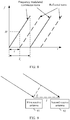
FIG. 6 is a schematic diagram of a frequency modulated continuous wave and a reflected wave of a target object in relative motion according to an embodiment of this application; -
FIG. 7 is a schematic diagram of a ranging principle of a sawtooth wave according to an embodiment of this application; -
FIG. 8 is a schematic diagram of a velocity measurement principle of a sawtooth wave according to an embodiment of this application; -
FIG. 9 is a schematic diagram of an angle measurement principle of a sawtooth wave according to an embodiment of this application; -
FIG. 10 is a schematic flowchart of a radar signal processing method according to an embodiment of this application; -
FIG. 11 is a schematic diagram 1 of a radar signal and a reflected signal according to an embodiment of this application; -
FIG. 12 is a schematic diagram 2 of a radar signal and a reflected signal according to an embodiment of this application; -
FIG. 13 is a schematic diagram 3 of a radar signal and a reflected signal according to an embodiment of this application; -
FIG. 14 is a schematic diagram 4 of a radar signal and a reflected signal according to an embodiment of this application; -
FIG. 15 is a schematic diagram 5 of a radar signal and a reflected signal according to an embodiment of this application; -
FIG. 16 is a schematic diagram 6 of a radar signal and a reflected signal according to an embodiment of this application; -
FIG. 17 is a schematic diagram 7 of a radar signal and a reflected signal according to an embodiment of this application; -
FIG. 18 is a schematic diagram 8 of a radar signal and a reflected signal according to an embodiment of this application; -
FIG. 19 is a schematic structural diagram 1 of a radar signal processing apparatus according to an embodiment of this application; -
FIG. 20 is a schematic structural diagram 2 of a radar signal processing apparatus according to an embodiment of this application; and -
FIG. 21 is a schematic structural diagram 3 of a radar signal processing apparatus according to an embodiment of this application. - Radar in the embodiments of this application may be applied to vehicle-to-everything (vehicle-to-everything, V2X), vehicle-to-vehicle (vehicle-to-vehicle, V2V) communication, vehicle-to-infrastructure (vehicle-to-infrastructure, V2I) communication, vehicle-to-pedestrian (vehicle-to-pedestrian, V2P) communication, and the like. An application scenario of the radar is not limited in this application.
- As shown in
FIG. 1 , the radar in the embodiments of this application may be installed on amotor vehicle 11, an unmannedaerial vehicle 12, arailway vehicle 13, abicycle 14, asignal light 15, avelocity measurement apparatus 16, aradar station 17, abase station 18, or the like. A position at which the radar is installed and a specific field to which the radar is applied are not limited in this application. In addition, it should be noted that the radar in the embodiments of this application may also be referred to as a detector or a detection apparatus. A working principle of the radar is to detect a corresponding target object by transmitting a signal (or referred to as a detection signal) and receiving a reflected signal obtained after reflection by the target object. The signal may be a radio signal or an electromagnetic wave signal. For ease of description, the signals may be collectively referred to as a radar signal. Further, the radar signal is periodically transmitted. For example, for a sawtooth wave, duration of a complete sawtooth waveform may be understood as a transmission period of a sawtooth wave radar signal. For another example, for a triangular wave, duration of a complete triangular waveform may be understood as a transmission period of a triangular wave radar signal. - The radar in the embodiments of this application may be applied to radar velocity measurement, ranging, angle measurement, and the like between vehicles, between a vehicle and an unmanned aerial vehicle, and between other apparatuses. For example, the radar may be applied to adaptive cruise control (adaptive cruise control, ACC), autonomous emergency braking (autonomous emergency braking, AEB), lane change assist (lane change assist, LCA), blind spot monitoring (blind spot monitoring, BSM), parking assistance (parking assistance, PA), and pedestrian detection (pedestrian detection, PD). A function to which the radar is applied is not limited in this application.
- The radar in the embodiments of this application may be millimeter-wave (millimeter wave, mmWave) radar, micrometer-wave radar, or the like. An attribute of an electromagnetic wave transmitted by the radar is not limited in this application.
- Specifically, a millimeter wave refers to an electromagnetic wave with a wavelength of 1 mm to 10 mm, and corresponds to a frequency range of 30 GHz to 300 GHz. Millimeter wave-related features are quite suitable for application to the vehicle-mounted field. High bandwidth means abundant frequency domain resources and a low antenna side lobe, thereby facilitating imaging or quasi-imaging. A small wavelength means a reduced size of a radar device and a reduced antenna diameter, and therefore a weight is reduced. A narrow beam means that in the case of a same antenna size, a millimeter-wave beam is much narrower than a micrometer-wave beam, and therefore there is high radar resolution. Strong penetration means that compared with laser radar and an optical system, the millimeter-wave radar has a better capability of penetrating smoke, dust, and fog, and can work around the clock.
- As shown in
FIG. 2 , an embodiment of this application provides radar. The radar includes anoscillator 201, adirectional coupler 202, a transmitantenna 203, a receiveantenna 204, amixer 205, and aprocessor 206. To clearly describe the solutions, in this embodiment of this application, description is provided by using an example in which a radar signal is a frequency modulated continuous wave. - The
oscillator 201 generates a frequency modulated continuous wave (frequency modulated continuous wave, FMCW), and outputs the frequency modulated continuous wave to thedirectional coupler 202. - The frequency modulated continuous wave may be a linear frequency modulated continuous wave. The linear frequency modulated continuous wave is an electromagnetic wave whose frequency linearly increases or decreases with time. That is, in a time unit, the frequency of the frequency modulated continuous wave is in a linear relationship with time. Alternatively, in a unit time, absolute values of frequency variations of the frequency modulated continuous wave are the same (for a sawtooth wave, frequency variations are the same; and for a triangular wave, absolute values of frequency variations of a rising edge and a falling edge are the same). In this embodiment of this application, a slope of the frequency of the frequency modulated continuous wave is a slope of the linear relationship between the frequency of the frequency modulated continuous wave and time (for details, refer to
FIG. 4 ). A sign of the slope is used to indicate whether the slope is a positive slope or a negative slope. When the frequency linearly increases with time, there is a rising edge, and the sign of the slope is positive. When the frequency linearly decreases with time, there is a falling edge, and the sign of the slope is negative. In this embodiment of this application, for example, a linear frequency modulated continuous wave is used for description, but there is no limitation that the frequency modulated continuous wave needs to be a linear frequency modulated continuous wave. - The
directional coupler 202 outputs the frequency modulated continuous wave to themixer 205 as a local-frequency signal, and outputs the frequency modulated continuous wave to the transmitantenna 203, and the transmitantenna 203 transmits the frequency modulated continuous wave. A reflected wave of the frequency modulated continuous wave is obtained after the frequency modulated continuous wave is reflected by a target object. - The receive
antenna 204 receives the reflected wave of the frequency modulated continuous wave, and then outputs the reflected wave to themixer 205. - The
mixer 205 mixes the frequency modulated continuous wave and the reflected wave of the frequency modulated continuous wave to obtain an intermediate frequency (intermediate frequency, IF) signal. The intermediate frequency signal is a signal formed by a difference between frequencies of the frequency modulated continuous wave and the reflected wave of the frequency modulated continuous wave at a same moment. That is, a frequency of the intermediate frequency signal is the difference between the frequencies of the frequency modulated continuous wave and the reflected wave of the frequency modulated continuous wave at the same moment. - The
mixer 205 filters, by using a low-pass filter, the intermediate frequency signal obtained through mixing, and then amplifies and outputs the intermediate frequency signal to theprocessor 206. Theprocessor 206 processes the intermediate frequency signal (for example, performs fast Fourier transformation and spectrum analysis on the intermediate frequency signal), to obtain at least one of range information, velocity information, and angle information of the target object. - In this embodiment of this application, the range information, the velocity information, and the angle information of the target object, or a range, a velocity, and an angle of the target object, or a relative range, a relative velocity, and a relative angle of the target object are all relative to the radar that transmits the frequency modulated continuous wave. A specific name is not limited in this application.
- It should be noted that when the radar is installed on a vehicle, the
processor 206 may send the at least one of the range information, the velocity information, and the angle information of the target object to a controller on the vehicle to control the vehicle. - A waveform of the frequency modulated continuous wave is usually a sawtooth wave or a triangular wave. The following describes a working principle of the radar in detail by using an example in which the frequency modulated continuous wave is a triangular wave.
-
FIG. 3 is a schematic diagram of a time amplitude of a frequency modulated continuous wave in a triangular wave form. A frequency of the frequency modulated continuous wave gradually increases with time in a time unit [0, T/2], and an amplitude of the frequency modulated continuous wave remains unchanged, where T is a period of the triangular wave.FIG. 4 is a schematic diagram of a time frequency of a frequency modulated continuous wave in a triangular wave form. A frequency of the frequency modulated continuous wave linearly increases with time by ΔF in a time unit [0, T /2], and the frequency of the frequency modulated continuous wave linearly decreases with time by ΔF in a time unit [T/2, T], where ΔF is a maximum variation range of the frequency of the frequency modulated continuous wave. - As shown in
FIG. 5 , if the target object is relatively static relative to the radar, the frequency modulated continuous wave and the reflected wave of the frequency modulated continuous wave are of a same shape, but there is a delay Δt. - The frequency modulated continuous wave x 1 is as follows:

the reflected wave x 2 of the frequency modulated continuous wave is as follows:
ω1(t) is an angular velocity of the frequency modulated continuous wave x 1, ϕ 1 is an initial phase of the frequency modulated continuous wave x 1, ω 2(t) is an angular velocity of the frequency modulated continuous wave x 2, and ϕ 2 is an initial phase of the reflected wave x 2 of the frequency modulated continuous wave. - The delay Δt between the frequency modulated continuous wave and the reflected wave x 2 of the frequency modulated continuous wave and the range R of the target object meet the following condition:

c is the speed of light. - The frequency modulated continuous wave and the reflected wave of the frequency modulated continuous wave are mixed in the
mixer 205, and the obtained intermediate frequency signal xout is as follows:
- In addition, as shown in
FIG. 5 , the frequency IF of the intermediate frequency signal is a product of the slope s of the frequency of the frequency modulated continuous wave and the delay Δt:
- T is the period of the triangular wave, and ΔF is the maximum variation range of the frequency modulated continuous wave.
- Therefore, the range R of the target object is as follows:

- It may be learned from the foregoing deduction that for the target object that is relatively static relative to the radar, there is a linear relationship between the difference (the frequency IF of the intermediate frequency signal) between the frequencies of the frequency modulated continuous wave and the reflected wave of the frequency modulated continuous wave at the same moment and the delay Δt between the frequency modulated continuous wave and the reflected wave of the frequency modulated continuous wave. That is, a longer range of the target object indicates a longer time for the radar to receive the reflected wave of the frequency modulated continuous wave and a larger difference (the frequency IF of the intermediate frequency signal) between the frequencies of the frequency modulated continuous wave and the reflected wave of the frequency modulated continuous wave at the same moment. Therefore, the range of the target object may be obtained by determining the frequency IF of the intermediate frequency signal.
- As shown in
FIG. 6 , if the target object is in relative motion relative to the radar, the frequency of the reflected wave of the frequency modulated continuous wave includes a Doppler frequency shift fd caused by relative motion of the target object. - Therefore, a frequency f b+ of an intermediate frequency signal corresponding to a rising edge of the triangular wave is as follows:

a frequency fb- of an intermediate frequency signal corresponding to a falling edge of the triangular wave is as follows:
- IF is a frequency of an intermediate frequency signal obtained when the target object is relatively static relative to the radar,


- Based on the formula 7 and the formula 8, it may be obtained, with reference to the formula 5, that the range R of the target object that is in relative motion relative to the radar is as follows:


- It may be learned from the foregoing deduction that for the target object that is in relative motion relative to the radar, the range information or the velocity information of the target object may be obtained by detecting the frequency f b+ of the intermediate frequency signal of the rising edge of the triangular wave and the frequency fb- of the intermediate frequency signal of the falling edge of the triangular wave.
- The working principle of the radar is described in detail below by using an example in which the frequency modulated continuous wave is a sawtooth wave.
- A ranging principle of a sawtooth wave is similar to that of a triangular wave. As shown in
FIG. 7 , there is a delay τ between the frequency modulated continuous wave and the reflected wave of the frequency mo the second time undulated continuous wave, and a period of the sawtooth wave is Tc . - The frequency modulated continuous wave x 1 is as follows:

the reflected wave x 2 of the frequency modulated continuous wave is as follows:
ω 1 is an angular velocity of the frequency modulated continuous wave x 1, and φ 1 is an initial phase of the frequency modulated continuous wave x 1. - An initial phase φ 0 of the intermediate frequency signal is a difference between a phase of the frequency modulated continuous wave x 1 and a phase of the reflected wave x 2 of the frequency modulated continuous wave:

- As shown in the formula 3,


- In this case, the range of the target object is as follows:


- It may be learned from the foregoing deduction that the relative range between the target object and the radar may be obtained by detecting the phase of the intermediate frequency signal.
- To measure the velocity of the object, as shown in
FIG. 8 , the radar transmits two frequency modulated continuous waves at a time interval Tc , and receives reflected waves of the two frequency modulated continuous waves, to obtain two intermediate frequency signals. The target object moves by a range of ΔR = vTc in the time Tc , where v is a moving velocity of the target object. Therefore, a phase difference Δφ that is between the two intermediate frequency signals and that is obtained based on theformula 14 is as follows:
λ is a wavelength of the frequency modulated continuous wave. Therefore, the velocity v of the target object is as follows:
- An angle measurement principle of the radar is also an extension of the ranging principle. As shown in
FIG. 9 , the radar may include a first receiveantenna 91 and a second receiveantenna 92. A range between the two receive antennas is l. The reflected wave of the frequency modulated continuous wave arrives at the two receive antennas at different ranges. The range l between the two receive antennas is far less than the range between the target object and the radar. Therefore, directions of the reflected waves received by the two receive antennas may be approximately parallel, and two intermediate frequency signals may be obtained. It is obtained, based on the ranging principle, that phases of the two intermediate frequency signals are different, and a transmission angle may be deduced based on a difference between the phases of the two intermediate frequency signals. - As described in the
formula 16, the difference between the phases of the two intermediate frequency signals is

- In the embodiments of this application, two frequency modulated continuous waves may be transmitted on different frequency bands by using same radar, reflected waves of the two frequency modulated continuous waves are correspondingly received, and intermediate frequency signals corresponding to the two frequency modulated continuous waves are obtained by using the method described above, to obtain at least one of range information, velocity information, and angle information of a target object.
- It should be noted that a frequency band in the embodiments of this application may be replaced with a frequency band. If two frequency bands are the same, it indicates that bandwidth, a minimum frequency, and a maximum frequency of the two frequency bands are the same.
- An embodiment of this application provides a radar signal processing method. The method is applied to a first apparatus. The first apparatus may be the radar described above or another apparatus with a control function, and the apparatus may be independent of or integrated into radar. As shown in
FIG. 10 , the radar signal processing method includes the following steps. - S101. Transmit a first radar signal on a first frequency band.
- Optionally, the first radar signal may be a first frequency modulated continuous wave.
- In an optional design, an initial frequency of the first radar signal is a minimum frequency of the first frequency band. In this design, transmit power of the first radar signal increases with time.
- In another optional design, an initial frequency of the first radar signal is a maximum frequency of the first frequency band. In this design, transmit power of the first radar signal decreases with time.
- Optionally, the transmitting a first radar signal is transmitting the first radar signal in a first time unit. Further, optionally, an initial moment for transmitting the first radar signal is a start moment of the first time unit.
- S102. Transmit a second radar signal on a second frequency band.
- Optionally, the second radar signal is a second frequency modulated continuous wave.
- In an optional design, an initial frequency of the second radar signal is a minimum frequency of the second frequency band. In this design, transmit power of the second radar signal increases with time.
- In another optional design, an initial frequency of the second radar signal is a maximum frequency of the second frequency band. In this design, transmit power of the second radar signal decreases with time.
- Optionally, the transmitting a second radar signal is transmitting the second radar signal in the first time unit. Further, optionally, an initial moment for transmitting the second radar signal is the start moment of the first time unit.
- In an optional design, the first frequency band and the second frequency band may not completely overlap in frequency domain, as shown in
FIG. 11 . Herein, that the first frequency band and the second frequency band do not completely overlap means that the first frequency band is different from the second frequency band, and any one of the frequency bands is not included in the other frequency band. Specifically, as shown inFIG. 12 , the first frequency band and the second frequency band do not overlap at all in frequency domain. - In a possible implementation, as shown in
FIG. 11 andFIG. 12 , the first radar signal and the second radar signal are transmitted in a first time unit T c1, duration of the first radar signal may be the same as duration of the second radar signal, and a length of the first time unit T c1 is equal to the duration. For example, the first time unit is a frequency sweep time of the first radar signal and the second radar signal. Herein, it should be noted that the first time unit may alternatively be understood as a "frequency sweep period", namely, a time unit in which both the first radar signal and the second radar signal complete frequency sweep. Further, the first time unit may be understood as each frequency sweep period. - In another possible implementation, as shown in
FIG. 13 , duration of the first radar signal may be different from duration of the second radar signal. For example, the first radar signal is transmitted in a second time unit T c2, and a length of the second time unit T c2 is equal to the duration of the first radar signal; and the second radar signal is transmitted in a third time unit T c3, and a length of the third time unit T c3 is equal to the duration of the second radar signal, where T c2 ≠ T c3. Further, the length of the first time unit T c1 is greater than or equal to the length of the second time unit T c2, and is greater than or equal to the length of the third time unit T c3 . - It should be noted that the duration may also be referred to as a frequency sweep time or the like. A specific name is not limited in this embodiment of this application. A linear frequency modulated continuous wave is used as an example. In each transmission period, a signal is transmitted from an initial frequency, and the initial frequency linearly increases to a maximum frequency in the transmission period (or linearly decreases to a minimum frequency in the transmission period) after specific duration. The duration may be referred to as duration a frequency sweep time of the linear frequency modulated continuous wave. Optionally, for a frequency modulated continuous wave that is periodically transmitted, the duration or the frequency sweep time may be one transmission period or half a transmission period. For example, for a sawtooth wave, the duration or the frequency sweep time may be a time length or a quantity of symbols of one period; and for a triangular wave, the duration or the frequency sweep time may be half a time length or half a quantity of symbols of one period, namely, half a period.
- A feature "unit time" is introduced in the following possible implementations. The unit time may be the first time unit, or may be any time period that is used as a calculation unit and that is in the first time unit, for example, one symbol, a plurality of symbols, one slot (slot), or one subframe. The unit time is not specifically limited in this embodiment of this application provided that a change relationship between a frequency of a radar signal or a frequency modulated continuous wave and time is clearly described.
- In a possible implementation, a sign of a slope of a frequency of the first radar signal is the same as a sign of a slope of a frequency of the second radar signal. The slope herein may be described as a variation of a frequency of a linear frequency modulated continuous wave in a unit time. Alternatively, frequencies of the first radar signal and the second radar signal increase with time in a unit time, or frequencies of the first radar signal and the second radar signal decrease with time in a unit time. For example, as shown in
FIG. 11 to FIG. 13 , in a unit time, the frequency of the first radar signal and the frequency of the second radar signal linearly increase with time, and a frequency variation is a positive value. Alternatively, as shown inFIG. 14 , in a unit time, the frequency of the first radar signal and the frequency of the second radar signal decrease linearly with time, and a frequency variation is a negative value. - In a possible implementation, an absolute value of a slope of a frequency of the first radar signal is the same as an absolute value of a slope of a frequency of the second radar signal. Alternatively, in a unit time, an absolute value of a frequency variation of the first radar signal is the same as an absolute value of a frequency variation of the second radar signal.
- Further, the first radar signal and the second radar signal are transmitted by using the start moment of the first time unit as the initial moment, and the frequencies of the first radar signal and the second radar signal change by a same frequency variation in a unit time. It may be understood that the first radar signal and the second radar signal are respectively transmitted on the first frequency band and the second frequency band, but have a same waveform in the first time unit. Further, the duration of the first radar signal is the same as the duration of the second radar signal (both the duration of the first radar signal and the duration of the second radar signal are the length of the first time unit). In this case, the first radar signal and the second radar signal may be periodically transmitted on the respective frequency bands by using the length of the first time unit as a period.
- In this possible implementation, optionally, the slope of the frequency of the first radar signal is the same as the slope of the frequency of the second radar signal. Alternatively, the frequency variations of the first radar signal and the second radar signal in the unit time are the same. For example, both the slope of the frequency of the first radar signal and the slope of the frequency of the second radar signal are 1.
- In this possible implementation, still optionally, the slope of the frequency of the first radar signal and the slope of the frequency of the second radar signal are opposite in sign. Alternatively, the frequency variations of the first radar signal and the second radar signal in the unit time are opposites. For example, as shown in
FIG. 15 , the frequency of the first radar signal linearly increases with time, and the frequency of the second radar signal linearly decreases with time. In this case, a sign of the slope of the frequency of the first radar signal is positive, and a sign of the slope of the frequency of the second radar signal is negative. Alternatively, as shown inFIG. 16 , the frequency of the first radar signal linearly decreases with time, and the frequency of the second radar signal linearly increases with time. In this case, a sign of the slope of the frequency of the first radar signal is negative, and a sign of the slope of the frequency of the second radar signal is positive. Alternatively, as shown inFIG. 17 , in a previous time unit, the frequency of the first radar signal linearly increases with time, and the frequency of the second radar signal linearly decreases with time; and in a current time unit, the frequency of the first radar signal linearly decreases with time, and the frequency of the second radar signal linearly increases with time. Alternatively, as shown inFIG. 18 , in a previous time unit, the frequency of the first radar signal linearly decreases with time, and the frequency of the second radar signal linearly increases with time; and in a current time unit, the frequency of the first radar signal linearly increases with time, and the frequency of the second radar signal linearly decreases with time. - When the slope of the frequency of the first radar signal and the slope of the frequency of the second radar signal are opposite in sign, a rising edge and a falling edge of a triangular wave may be sent in one time unit, which is different from a case, shown in
FIG. 4 , in which a rising edge is first sent in a time unit, and then a falling edge is sent in a next time unit. In this case, a time for sending the rising edge and the falling edge of the triangular wave is reduced by half. Correspondingly, a time for receiving a reflected wave of the rising edge and a reflected wave of the falling edge is reduced by half. Therefore, time consumed for measuring range information of a target object by using a formula 9 or measuring velocity information of a target object by using a formula 10 is reduced by half. In addition, resolution of radar for measuring the range information and the velocity information is kept unchanged. - Further, in a possible implementation, a slope of a frequency of the first radar signal and a slope of a frequency of the second radar signal are opposites. For example, the slope of the frequency of the first radar signal is 1, and the slope of the frequency of the second radar signal is -1.
- S103. Receive a first reflected signal and a second reflected signal.
- The first reflected signal is an electromagnetic wave obtained after the first radar signal or the first frequency modulated continuous wave is reflected by the target object, and the second reflected signal is an electromagnetic wave obtained after the second radar signal or the second frequency modulated continuous wave is reflected by the target object.
- S104. Obtain at least one of the range information, the velocity information, and angle information of the target object.
- In a possible implementation, the at least one of the range information, the velocity information, and the angle information is obtained based on the first radar signal and the first reflected signal. For example, a first intermediate frequency signal is obtained based on the first radar signal and the first reflected signal; and the at least one of the range information, the velocity information, and the angle information is obtained based on the first intermediate frequency signal
- Alternatively, in another possible implementation, the at least one of the range information, the velocity information, and the angle information is obtained based on the second radar signal and the second reflected signal. For example, a second intermediate frequency signal is obtained based on the second radar signal and the second reflected signal; and the at least one of the range information, the velocity information, and the angle information is obtained based on the second intermediate frequency signal.
- Alternatively, in still another possible implementation, the at least one of the range information, the velocity information, and the angle information is obtained based on the first radar signal, the first reflected signal, the second radar signal, and the second reflected signal. For example, a first intermediate frequency signal is obtained based on the first radar signal and the first reflected signal; a second intermediate frequency signal is obtained based on the second radar signal and the second reflected signal; and the at least one of the range information, the velocity information, and the angle information is obtained based on the first intermediate frequency signal and the second intermediate frequency signal
- For how to obtain the at least one of the range information, the velocity information, and the angle information based on the intermediate frequency signal, refer to the foregoing description. Details are not described herein again.
- According to the radar signal processing method provided in this embodiment of this application, two radar signals are transmitted on different frequency bands, and reflected signals of the two radar signals are correspondingly received, to obtain the at least one of the range information, the velocity information, and the angle information of the target object. Radar signals can be transmitted by using inconsecutive frequency domain resources, and therefore frequency sweep bandwidth of radar is expanded. In this way, range resolution of the radar is improved.
- An embodiment of this application further provides a radar signal processing apparatus, which may be configured to perform the radar signal processing method in the foregoing implementations. In this embodiment of this application, the radar signal processing apparatus may be divided into function modules based on the foregoing method example. For example, each function module may be obtained through division based on each corresponding function, or two or more functions may be integrated into one processing module. The integrated module may be implemented in a form of hardware, or may be implemented in a form of a software functional module. It should be noted that, in this application, module division is exemplary, and is merely a logical function division. In actual implementation, another division manner may be used.
- When each function module is obtained through division based on each corresponding function,
FIG. 19 is a possible schematic structural diagram of a radar signal processing apparatus in the foregoing embodiment. A radarsignal processing apparatus 19 may include areceiving unit 1911, an obtainingunit 1912, and atransmitting unit 1913. The units are configured to support the radar signal processing apparatus in performing the related method inFIG. 10 . The radar signal processing apparatus provided in this application is configured to perform the foregoing radar signal processing method. Therefore, for corresponding features of the radar signal processing apparatus and beneficial effects that can be achieved by the radar signal processing apparatus, refer to the beneficial effects in the corresponding implementations provided above. Details are not described herein again. - For example, the receiving
unit 1911 is configured to support the radarsignal processing apparatus 19 in performing the process S103 inFIG. 10 . The obtainingunit 1912 is configured to support the radarsignal processing apparatus 19 in performing the process S104 inFIG. 10 . Thetransmitting unit 1913 is configured to support the radarsignal processing apparatus 19 in performing the processes S101 and S102 inFIG. 10 . All related content of the steps in the foregoing method embodiment may be cited in function description of corresponding function modules. Details are not described herein again. - In a possible implementation, the
transmitting unit 1913 is configured to transmit a first radar signal on a first frequency band. The transmitting unit is further configured to transmit a second radar signal on a second frequency band. The receivingunit 1911 is configured to receive a first reflected signal and a second reflected signal. The first reflected signal is an electromagnetic wave obtained after the first radar signal is reflected by a target object, and the second reflected signal is an electromagnetic wave obtained after the second radar signal is reflected by the target object. The obtainingunit 1912 is configured to obtain at least one of range information, velocity information, and angle information of the target object. - In a possible implementation, the obtaining
unit 1912 is specifically configured to: obtain the at least one of the range information, the velocity information, and the angle information based on the first radar signal and the first reflected signal; or obtain the at least one of the range information, the velocity information, and the angle information based on the second radar signal and the second reflected signal; or obtain the at least one of the range information, the velocity information, and the angle information based on the first radar signal, the first reflected signal, the second radar signal, and the second reflected signal. - In a possible implementation, the first radar signal and the second radar signal are transmitted in a first time unit, duration of the first radar signal is the same as duration of the second radar signal, and a length of the first time unit is equal to the duration.
- In a possible implementation, the first frequency band and the second frequency band do not completely overlap in frequency domain.
- In a possible implementation, at least one of the first radar signal and the second radar signal is a linear frequency modulated continuous wave, and the linear frequency modulated continuous wave is an electromagnetic wave whose frequency linearly increases or decreases with time.
- In a possible implementation, frequency variations of the first radar signal and the second radar signal in a unit time are opposites.
- In a possible implementation, a frequency of the first radar signal and a frequency of the second radar signal increase with time in a unit time, or a frequency of the first radar signal and a frequency of the second radar signal decrease with time in a unit time.
- In a possible implementation, frequency variations of the first radar signal and the second radar signal in the unit time are the same.
-
FIG. 20 is another possible schematic structural diagram of a radar signal processing apparatus in the foregoing embodiment. A radarsignal processing apparatus 20 includes aprocessing module 2022 and acommunications module 2023. Optionally, the radarsignal processing apparatus 20 may further include astorage module 2021. The modules are configured to support the radar signal processing apparatus in performing the related method inFIG. 10 . - In a possible manner, the
processing module 2022 is configured to: control and manage an action of the radarsignal processing apparatus 20, or execute a corresponding processing function, for example, execute a function of the obtainingunit 1912. Thecommunications module 2023 is configured to support a function of communication between the radarsignal processing apparatus 20 and another device, for example, execute functions of thereceiving unit 1911 and thetransmitting unit 1913. Thestorage module 2021 is configured to store program code and/or data of the radar signal processing apparatus. - The
processing module 2022 may be a processor or a controller, such as may be a central processing unit (central processing unit, CPU), a general-purpose processor, a digital signal processor (digital signal processing, DSP), an application-specific integrated circuit (application-specific integrated circuit, ASIC), a field programmable gate array (field programmable gate array, FPGA), or another programmable logical device, a transistor logical device, a hardware component, or any combination thereof. The processor may implement or execute various example logical blocks, modules, and circuits described with reference to content disclosed in this application. The processor may be a combination of processors implementing a computing function, for example, a combination of one or more microprocessors, or a combination of the DSP and a microprocessor. Thecommunications module 2023 may be a network interface, a communications interface, or the like. Thestorage module 2021 may be a memory. - In a possible manner, the
processing module 2022 may be aprocessor 2132 inFIG. 21 , thecommunications module 2023 may be anRF circuit 2133 inFIG. 21 , and thestorage module 2021 may be amemory 2131 inFIG. 21 . One or more programs are stored in the memory, and the one or more programs include an instruction. When the instruction is executed by the radar signal processing apparatus, the radar signal processing apparatus is enabled to perform the related method inFIG. 10 . - An embodiment of this application further provides a radar signal processing apparatus, including a processor and a memory. The memory is configured to store a program, and the processor invokes the program stored in the memory, so that the radar signal processing apparatus performs the related method in
FIG. 10 . - An embodiment of this application further provides a computer storage medium that stores one or more programs. The computer storage medium stores a computer program. When the computer program is executed by a processor, a radar signal processing apparatus is enabled to perform the related method in
FIG. 10 . - An embodiment of this application further provides a computer program product including an instruction. When the computer program product runs on a radar signal processing apparatus, the radar signal processing apparatus is enabled to perform the related method in
FIG. 10 . - An embodiment of this application provides a chip system. The chip system includes a processor, configured to support a radar signal processing apparatus in performing the related method in
FIG. 10 . For example, a first radar signal is transmitted on a first frequency band; a second radar signal is transmitted on a second frequency band; a first reflected signal and a second reflected signal are received, where the first reflected signal is an electromagnetic wave obtained after the first radar signal is reflected by a target object, and the second reflected signal is an electromagnetic wave obtained after the second radar signal is reflected by the target object; and at least one of range information, velocity information, and angle information of the target object is obtained. In a possible design, the chip system further includes a memory. The memory is configured to store a program instruction and data that are necessary for a terminal device. The chip system may include a chip and an integrated circuit, or may include a chip and another discrete device. This is not specifically limited in this embodiment of this application. - The radar signal processing apparatus, the computer storage medium, the computer program product, or the chip system provided in this application is configured to perform the radar signal processing method described above. Therefore, for beneficial effects that can be achieved by the radar signal processing apparatus, the computer storage medium, the computer program product, or the chip system, refer to the beneficial effects in the implementations provided above. Details are not described herein again.
- It should be understood that sequence numbers of the foregoing processes do not mean execution sequences in various embodiments of this application. The execution sequences of the processes should be determined according to functions and internal logic of the processes, and should not be construed as any limitation on the implementation processes of the embodiments of this application.
- A person of ordinary skill in the art may be aware that, in combination with the examples described in the embodiments disclosed in this specification, units and algorithm steps may be implemented by electronic hardware or a combination of computer software and electronic hardware. Whether the functions are performed by hardware or software depends on particular applications and design constraint conditions of the technical solutions. A person skilled in the art may use different methods to implement the described functions for each particular application, but it should not be considered that the implementation goes beyond the scope of this application.
- It may be clearly understood by a person skilled in the art that, for the purpose of convenient and brief description, for a detailed working process of the foregoing system, apparatus, and unit, refer to a corresponding process in the foregoing method embodiments, and details are not described herein again.
- In the several embodiments provided in this application, it should be understood that the disclosed system, device, and method may be implemented in other manners. For example, the described device embodiment is merely exemplary. For example, the unit division is merely logical function division and may be other division in actual implementation. For example, a plurality of units or components may be combined or integrated into another system, or some features may be ignored or not performed. In addition, the displayed or discussed mutual couplings or direct couplings or communication connections may be implemented through some interfaces. The indirect couplings or communication connections between the devices or units may be implemented in electronic, mechanical, or other forms.
- The units described as separate parts may or may not be physically separate, and parts displayed as units may or may not be physical units, may be located in one position, or may be distributed on a plurality of network units. Some or all of the units may be selected based on actual requirements to achieve the objectives of the solutions of the embodiments.
- In addition, functional units in the embodiments of this application may be integrated into one processing unit, or each of the units may exist alone physically, or two or more units are integrated into one unit.
- All or some of the foregoing embodiments may be implemented by using software, hardware, firmware, or any combination thereof. When a software program is used to implement the embodiments, the embodiments may be implemented completely or partially in a form of a computer program product. The computer program product includes one or more computer instructions. When the computer program instructions are loaded and executed on the computer, the procedure or functions according to the embodiments of this application are all or partially generated. The computer may be a general-purpose computer, a dedicated computer, a computer network, or other programmable apparatuses. The computer instructions may be stored in a computer-readable storage medium or may be transmitted from a computer-readable storage medium to another computer-readable storage medium. For example, the computer instructions may be transmitted from a website, computer, server, or data center to another website, computer, server, or data center in a wired (for example, a coaxial cable, an optical fiber, or a digital subscriber line (Digital Subscriber Line, DSL)) or wireless (for example, infrared, radio, or microwave) manner. The computer-readable storage medium may be any usable medium accessible by a computer, or a data storage device, such as a server or a data center, integrating one or more usable media. The usable medium may be a magnetic medium (for example, a floppy disk, a hard disk, or a magnetic tape), an optical medium (for example, a DVD), a semiconductor medium (for example, a solid-state drive (Solid State Disk, SSD)), or the like.
- The foregoing descriptions are merely specific implementations of this application, but are not intended to limit the protection scope of this application. Any variation or replacement readily figured out by a person skilled in the art within the technical scope disclosed in this application shall fall within the protection scope of this application. Therefore, the protection scope of this application shall be subject to the protection scope of the claims.
Claims (18)
- A radar signal processing method, wherein the method is applied to a first apparatus and comprises:transmitting a first radar signal on a first frequency band;transmitting a second radar signal on a second frequency band;receiving a first reflected signal and a second reflected signal, wherein the first reflected signal is an electromagnetic wave obtained after the first radar signal is reflected by a target object, and the second reflected signal is an electromagnetic wave obtained after the second radar signal is reflected by the target object; andobtaining at least one of range information, velocity information, and angle information of the target object.
- The method according to claim 1, wherein the obtaining at least one of range information, velocity information, and angle information of the target object comprises:obtaining the at least one of the range information, the velocity information, and the angle information based on the first radar signal and the first reflected signal; orobtaining the at least one of the range information, the velocity information, and the angle information based on the second radar signal and the second reflected signal; orobtaining the at least one of the range information, the velocity information, and the angle information based on the first radar signal, the first reflected signal, the second radar signal, and the second reflected signal.
- The method according to claim 1 or 2, wherein
the first radar signal and the second radar signal are transmitted in a first time unit; and
duration of the first radar signal is the same as duration of the second radar signal, and a length of the first time unit is equal to the duration. - The method according to any one of claims 1 to 3, wherein
the first frequency band and the second frequency band do not completely overlap in frequency domain. - The method according to any one of claims 1 to 4, wherein at least one of the first radar signal and the second radar signal is a linear frequency modulated continuous wave, and the linear frequency modulated continuous wave is an electromagnetic wave whose frequency linearly increases or decreases with time.
- The method according to claim 5, wherein frequency variations of the first radar signal and the second radar signal in a unit time are opposites.
- The method according to claim 5, wherein a frequency of the first radar signal and a frequency of the second radar signal increase with time in a unit time; or a frequency of the first radar signal and a frequency of the second radar signal decrease with time in a unit time.
- The method according to claim 7, wherein the frequency variations of the first radar signal and the second radar signal in the unit time are the same.
- A radar signal processing apparatus, comprising:a transmitting unit, configured to transmit a first radar signal on a first frequency band, whereinthe transmitting unit is further configured to transmit a second radar signal on a second frequency band;a receiving unit, configured to receive a first reflected signal and a second reflected signal, wherein the first reflected signal is an electromagnetic wave obtained after the first radar signal is reflected by a target object, and the second reflected signal is an electromagnetic wave obtained after the second radar signal is reflected by the target object; andan obtaining unit, configured to obtain at least one of range information, velocity information, and angle information of the target object.
- The apparatus according to claim 9, wherein the obtaining unit is specifically configured to:obtain the at least one of the range information, the velocity information, and the angle information based on the first radar signal and the first reflected signal; orobtain the at least one of the range information, the velocity information, and the angle information based on the second radar signal and the second reflected signal; orobtain the at least one of the range information, the velocity information, and the angle information based on the first radar signal, the first reflected signal, the second radar signal, and the second reflected signal.
- The apparatus according to claim 9 or 10, wherein
the first radar signal and the second radar signal are transmitted in a first time unit; and
duration of the first radar signal is the same as duration of the second radar signal, and a length of the first time unit is equal to the duration. - The apparatus according to any one of claims 9 to 11, wherein
the first frequency band and the second frequency band do not completely overlap in frequency domain. - The apparatus according to any one of claims 9 to 12, wherein at least one of the first radar signal and the second radar signal is a linear frequency modulated continuous wave, and the linear frequency modulated continuous wave is an electromagnetic wave whose frequency linearly increases or decreases with time.
- The apparatus according to claim 13, wherein frequency variations of the first radar signal and the second radar signal in a unit time are opposites.
- The apparatus of claim 13, wherein a frequency of the first radar signal and a frequency of the second radar signal increase with time in a unit time; or a frequency of the first radar signal and a frequency of the second radar signal decrease with time in a unit time.
- The apparatus according to claim 15, wherein frequency variations of the first radar signal and the second radar signal in the unit time are the same.
- A radar signal processing apparatus, applied to the radar signal processing method according to any one of claims 1 to 8.
- A storage medium, wherein the storage medium stores a computer program; and when the computer program is executed by a processor, the radar signal processing method according to any one of claims 1 to 8 is implemented.
Applications Claiming Priority (2)
| Application Number | Priority Date | Filing Date | Title |
|---|---|---|---|
| CN201811256435.7A CN111103580B (en) | 2018-10-26 | 2018-10-26 | Radar signal processing method and device |
| PCT/CN2019/113249 WO2020083369A1 (en) | 2018-10-26 | 2019-10-25 | Radar signal processing method and device |
Publications (2)
| Publication Number | Publication Date |
|---|---|
| EP3842833A1 true EP3842833A1 (en) | 2021-06-30 |
| EP3842833A4 EP3842833A4 (en) | 2021-10-20 |
Family
ID=70331955
Family Applications (1)
| Application Number | Title | Priority Date | Filing Date |
|---|---|---|---|
| EP19876754.3A Pending EP3842833A4 (en) | 2018-10-26 | 2019-10-25 | RADAR SIGNAL PROCESSING METHOD AND DEVICE |
Country Status (4)
| Country | Link |
|---|---|
| US (1) | US11982731B2 (en) |
| EP (1) | EP3842833A4 (en) |
| CN (1) | CN111103580B (en) |
| WO (1) | WO2020083369A1 (en) |
Families Citing this family (13)
| Publication number | Priority date | Publication date | Assignee | Title |
|---|---|---|---|---|
| JP6713946B2 (en) * | 2017-03-31 | 2020-06-24 | 株式会社Soken | In-vehicle radar device |
| CN114002677B (en) * | 2020-07-28 | 2025-06-06 | 华为技术有限公司 | A distributed radar |
| CN112534299B (en) * | 2020-08-05 | 2022-03-29 | 华为技术有限公司 | Transmitting method and device based on radar signals |
| CN116209918B (en) * | 2020-08-14 | 2025-06-06 | 华为技术有限公司 | Radar signal processing unit and waveform processing method |
| CN111983593B (en) * | 2020-08-21 | 2024-05-10 | 无锡市雷华科技有限公司 | High-precision double-base linear frequency modulation continuous wave radar synchronization system |
| CN112654879B (en) * | 2020-12-11 | 2022-04-15 | 华为技术有限公司 | Anti-interference method, device and system based on vehicle-mounted millimeter wave radar and vehicle |
| EP4261570B1 (en) * | 2020-12-28 | 2025-11-26 | Shenzhen Yinwang Intelligent Technologies Co., Ltd. | Detection method, detection device, detection system, and radar |
| CN113687358B (en) * | 2021-08-25 | 2024-06-21 | 深圳市万集科技有限公司 | Target object recognition method, device, electronic device and storage medium |
| CN113901948B (en) * | 2021-11-04 | 2024-10-29 | 海信集团控股股份有限公司 | Learning gesture recognition method and equipment |
| CN114325589B (en) * | 2021-12-25 | 2024-08-30 | 北京神星科技有限公司 | FMCW radar device with random parameters and signal generation and processing method |
| CN114966663A (en) * | 2022-05-16 | 2022-08-30 | 青岛淄柴博洋柴油机股份有限公司 | A method and system for measuring rotational speed of marine diesel engine based on continuous wave radar |
| CN115327522B (en) * | 2022-08-19 | 2023-06-02 | 山东高速工程检测有限公司 | Bridge monitoring method and system based on millimeter wave radar |
| CN116881691B (en) * | 2023-07-10 | 2026-01-23 | 极望智能(厦门)科技有限公司 | Biological detection method for living body in security inspection scene |
Family Cites Families (16)
| Publication number | Priority date | Publication date | Assignee | Title |
|---|---|---|---|---|
| JP2001083238A (en) * | 1999-09-16 | 2001-03-30 | Mitsubishi Electric Corp | Radar device and distance measuring method |
| JP5752040B2 (en) * | 2008-09-11 | 2015-07-22 | ニコン・メトロロジー・エヌヴェ | Compact optical fiber arrangement for anti-chirp FMCW coherent laser radar |
| FR2965064B1 (en) * | 2010-09-22 | 2012-10-05 | Onera (Off Nat Aerospatiale) | TELEMETRIC MEASUREMENT USING A HETERODYNE DETECTION LIDAR TYPE DEVICE |
| CN102169180A (en) * | 2010-12-22 | 2011-08-31 | 中国科学院上海微系统与信息技术研究所 | Dual-beam three-antenna radar and method for detecting traffic information of microwave |
| JP6036257B2 (en) * | 2012-12-17 | 2016-11-30 | 株式会社デンソー | FMCW radar equipment |
| CN103630888B (en) * | 2013-02-27 | 2017-03-22 | 中国科学院电子学研究所 | High-precision real-time microwave velocity and distance measuring device based on symmetrical triangle LFMCW (Linear Frequency Modulation Continuous Wave) radar |
| CN104345308A (en) * | 2013-07-24 | 2015-02-11 | 均利科技股份有限公司 | Vehicle detector and method for measuring vehicle distance and vehicle speed |
| CN103728593B (en) * | 2014-01-13 | 2015-10-21 | 武汉大学 | A kind of method realizing ground wave OTHR simultaneously multifrequency transmitting/receiving |
| JP6548376B2 (en) * | 2014-10-06 | 2019-07-24 | 日本電産株式会社 | Radar system, radar signal processing device, vehicle travel control device and method, and computer program |
| CN104459683B (en) * | 2014-12-12 | 2017-03-01 | 重庆大学 | Multiple target displacement high-precision measuring method based on microwave radar and system |
| DE102015109463A1 (en) * | 2015-06-15 | 2016-12-15 | Endress + Hauser Gmbh + Co. Kg | Method for checking the functionality of a radar-based level gauge |
| TW201734404A (en) * | 2016-03-30 | 2017-10-01 | 啟碁科技股份有限公司 | Angle estimating method and radar system |
| US10451723B2 (en) * | 2016-12-20 | 2019-10-22 | National Chung-Shan Institute Of Science & Technology | Signal processing apparatus of a continuous-wave (CW) radar sensing system |
| CN107688178A (en) * | 2017-08-25 | 2018-02-13 | 上海通趣科技有限公司 | A kind of sawtooth waveforms ranging and range rate method based on 77GHz millimetre-wave radars |
| US10564277B2 (en) * | 2018-01-30 | 2020-02-18 | Oculii Corp. | Systems and methods for interpolated virtual aperature radar tracking |
| GB201803239D0 (en) * | 2018-02-28 | 2018-04-11 | Secr Defence | A radio or sonic wave detector, transmitter, reciver and method thereof |
-
2018
- 2018-10-26 CN CN201811256435.7A patent/CN111103580B/en active Active
-
2019
- 2019-10-25 EP EP19876754.3A patent/EP3842833A4/en active Pending
- 2019-10-25 WO PCT/CN2019/113249 patent/WO2020083369A1/en not_active Ceased
-
2021
- 2021-04-23 US US17/238,276 patent/US11982731B2/en active Active
Also Published As
| Publication number | Publication date |
|---|---|
| CN111103580B (en) | 2023-06-27 |
| US20210239824A1 (en) | 2021-08-05 |
| US11982731B2 (en) | 2024-05-14 |
| WO2020083369A1 (en) | 2020-04-30 |
| EP3842833A4 (en) | 2021-10-20 |
| CN111103580A (en) | 2020-05-05 |
Similar Documents
| Publication | Publication Date | Title |
|---|---|---|
| US11982731B2 (en) | Radar signal processing method and apparatus | |
| US11754668B2 (en) | Detection method, detection apparatus, and system | |
| US12313734B2 (en) | Signal transmission method and apparatus | |
| US11971468B2 (en) | Method for detecting target object and corresponding detection apparatus | |
| US12204044B2 (en) | Method for detecting target object by using radio signal and related apparatus | |
| US20150323649A1 (en) | Method and device for sensing surrounding environment based on frequency modulated continuous wave radar | |
| WO2021008139A1 (en) | Detection method, signal sending method, and apparatuses | |
| CN113325373B (en) | Signal sending method and related device | |
| CN104730522A (en) | Method and device for sensing road environment based on frequency modulated continuous wave radar | |
| EP3451015B1 (en) | Method and apparatus for detecting object using radar of vehicle | |
| US12204043B2 (en) | Method for evaluating parameter of interfering signal and detection apparatus | |
| CN112014800B (en) | Method and device for transmitting radar signal | |
| US12517243B2 (en) | Information reporting method, information receiving method, and apparatus | |
| CN112153739A (en) | Communication method and device | |
| CN112433214A (en) | Radar signal sending method and device | |
| US10698105B2 (en) | Radar device and peak processing method | |
| CN113050041A (en) | Frequency band state judgment method and related equipment | |
| EP4513224A1 (en) | Signal sending method and receiving method and corresponding devices | |
| KR20220064109A (en) | Radar system for vehicle and method for operating the same | |
| JP2024171412A (en) | Wireless communication device, wireless communication method, and wireless communication program |
Legal Events
| Date | Code | Title | Description |
|---|---|---|---|
| STAA | Information on the status of an ep patent application or granted ep patent |
Free format text: STATUS: THE INTERNATIONAL PUBLICATION HAS BEEN MADE |
|
| PUAI | Public reference made under article 153(3) epc to a published international application that has entered the european phase |
Free format text: ORIGINAL CODE: 0009012 |
|
| STAA | Information on the status of an ep patent application or granted ep patent |
Free format text: STATUS: REQUEST FOR EXAMINATION WAS MADE |
|
| 17P | Request for examination filed |
Effective date: 20210322 |
|
| AK | Designated contracting states |
Kind code of ref document: A1 Designated state(s): AL AT BE BG CH CY CZ DE DK EE ES FI FR GB GR HR HU IE IS IT LI LT LU LV MC MK MT NL NO PL PT RO RS SE SI SK SM TR |
|
| A4 | Supplementary search report drawn up and despatched |
Effective date: 20210920 |
|
| RIC1 | Information provided on ipc code assigned before grant |
Ipc: G01S 13/02 20060101AFI20210914BHEP |
|
| DAV | Request for validation of the european patent (deleted) | ||
| DAX | Request for extension of the european patent (deleted) | ||
| STAA | Information on the status of an ep patent application or granted ep patent |
Free format text: STATUS: EXAMINATION IS IN PROGRESS |
|
| 17Q | First examination report despatched |
Effective date: 20230519 |
|
| RAP1 | Party data changed (applicant data changed or rights of an application transferred) |
Owner name: SHENZHEN YINWANG INTELLIGENTTECHNOLOGIES CO., LTD. |
|
| GRAP | Despatch of communication of intention to grant a patent |
Free format text: ORIGINAL CODE: EPIDOSNIGR1 |
|
| STAA | Information on the status of an ep patent application or granted ep patent |
Free format text: STATUS: GRANT OF PATENT IS INTENDED |
|
| INTG | Intention to grant announced |
Effective date: 20260408 |