EP3842711B1 - Air conditioning apparatus - Google Patents
Air conditioning apparatus Download PDFInfo
- Publication number
- EP3842711B1 EP3842711B1 EP20212681.9A EP20212681A EP3842711B1 EP 3842711 B1 EP3842711 B1 EP 3842711B1 EP 20212681 A EP20212681 A EP 20212681A EP 3842711 B1 EP3842711 B1 EP 3842711B1
- Authority
- EP
- European Patent Office
- Prior art keywords
- connection pipe
- refrigerant
- heat exchanger
- pipe
- indoor
- Prior art date
- Legal status (The legal status is an assumption and is not a legal conclusion. Google has not performed a legal analysis and makes no representation as to the accuracy of the status listed.)
- Active
Links
Images



Classifications
-
- F—MECHANICAL ENGINEERING; LIGHTING; HEATING; WEAPONS; BLASTING
- F25—REFRIGERATION OR COOLING; COMBINED HEATING AND REFRIGERATION SYSTEMS; HEAT PUMP SYSTEMS; MANUFACTURE OR STORAGE OF ICE; LIQUEFACTION SOLIDIFICATION OF GASES
- F25B—REFRIGERATION MACHINES, PLANTS OR SYSTEMS; COMBINED HEATING AND REFRIGERATION SYSTEMS; HEAT PUMP SYSTEMS
- F25B25/00—Machines, plants or systems, using a combination of modes of operation covered by two or more of the groups F25B1/00 - F25B23/00
- F25B25/005—Machines, plants or systems, using a combination of modes of operation covered by two or more of the groups F25B1/00 - F25B23/00 using primary and secondary systems
-
- F—MECHANICAL ENGINEERING; LIGHTING; HEATING; WEAPONS; BLASTING
- F25—REFRIGERATION OR COOLING; COMBINED HEATING AND REFRIGERATION SYSTEMS; HEAT PUMP SYSTEMS; MANUFACTURE OR STORAGE OF ICE; LIQUEFACTION SOLIDIFICATION OF GASES
- F25B—REFRIGERATION MACHINES, PLANTS OR SYSTEMS; COMBINED HEATING AND REFRIGERATION SYSTEMS; HEAT PUMP SYSTEMS
- F25B5/00—Compression machines, plants or systems, with several evaporator circuits, e.g. for varying refrigerating capacity
- F25B5/02—Compression machines, plants or systems, with several evaporator circuits, e.g. for varying refrigerating capacity arranged in parallel
-
- F—MECHANICAL ENGINEERING; LIGHTING; HEATING; WEAPONS; BLASTING
- F25—REFRIGERATION OR COOLING; COMBINED HEATING AND REFRIGERATION SYSTEMS; HEAT PUMP SYSTEMS; MANUFACTURE OR STORAGE OF ICE; LIQUEFACTION SOLIDIFICATION OF GASES
- F25B—REFRIGERATION MACHINES, PLANTS OR SYSTEMS; COMBINED HEATING AND REFRIGERATION SYSTEMS; HEAT PUMP SYSTEMS
- F25B41/00—Fluid-circulation arrangements
- F25B41/20—Disposition of valves, e.g. of on-off valves or flow control valves
- F25B41/22—Disposition of valves, e.g. of on-off valves or flow control valves between evaporator and compressor
-
- F—MECHANICAL ENGINEERING; LIGHTING; HEATING; WEAPONS; BLASTING
- F25—REFRIGERATION OR COOLING; COMBINED HEATING AND REFRIGERATION SYSTEMS; HEAT PUMP SYSTEMS; MANUFACTURE OR STORAGE OF ICE; LIQUEFACTION SOLIDIFICATION OF GASES
- F25B—REFRIGERATION MACHINES, PLANTS OR SYSTEMS; COMBINED HEATING AND REFRIGERATION SYSTEMS; HEAT PUMP SYSTEMS
- F25B41/00—Fluid-circulation arrangements
- F25B41/30—Expansion means; Dispositions thereof
- F25B41/39—Dispositions with two or more expansion means arranged in series, i.e. multi-stage expansion, on a refrigerant line leading to the same evaporator
-
- F—MECHANICAL ENGINEERING; LIGHTING; HEATING; WEAPONS; BLASTING
- F24—HEATING; RANGES; VENTILATING
- F24F—AIR-CONDITIONING; AIR-HUMIDIFICATION; VENTILATION; USE OF AIR CURRENTS FOR SCREENING
- F24F5/00—Air-conditioning systems or apparatus not covered by F24F1/00 or F24F3/00, e.g. using solar heat or combined with household units such as an oven or water heater
-
- F—MECHANICAL ENGINEERING; LIGHTING; HEATING; WEAPONS; BLASTING
- F25—REFRIGERATION OR COOLING; COMBINED HEATING AND REFRIGERATION SYSTEMS; HEAT PUMP SYSTEMS; MANUFACTURE OR STORAGE OF ICE; LIQUEFACTION SOLIDIFICATION OF GASES
- F25B—REFRIGERATION MACHINES, PLANTS OR SYSTEMS; COMBINED HEATING AND REFRIGERATION SYSTEMS; HEAT PUMP SYSTEMS
- F25B2313/00—Compression machines, plants or systems with reversible cycle not otherwise provided for
- F25B2313/003—Indoor unit with water as a heat sink or heat source
-
- F—MECHANICAL ENGINEERING; LIGHTING; HEATING; WEAPONS; BLASTING
- F25—REFRIGERATION OR COOLING; COMBINED HEATING AND REFRIGERATION SYSTEMS; HEAT PUMP SYSTEMS; MANUFACTURE OR STORAGE OF ICE; LIQUEFACTION SOLIDIFICATION OF GASES
- F25B—REFRIGERATION MACHINES, PLANTS OR SYSTEMS; COMBINED HEATING AND REFRIGERATION SYSTEMS; HEAT PUMP SYSTEMS
- F25B2313/00—Compression machines, plants or systems with reversible cycle not otherwise provided for
- F25B2313/007—Compression machines, plants or systems with reversible cycle not otherwise provided for three pipes connecting the outdoor side to the indoor side with multiple indoor units
-
- F—MECHANICAL ENGINEERING; LIGHTING; HEATING; WEAPONS; BLASTING
- F25—REFRIGERATION OR COOLING; COMBINED HEATING AND REFRIGERATION SYSTEMS; HEAT PUMP SYSTEMS; MANUFACTURE OR STORAGE OF ICE; LIQUEFACTION SOLIDIFICATION OF GASES
- F25B—REFRIGERATION MACHINES, PLANTS OR SYSTEMS; COMBINED HEATING AND REFRIGERATION SYSTEMS; HEAT PUMP SYSTEMS
- F25B2313/00—Compression machines, plants or systems with reversible cycle not otherwise provided for
- F25B2313/023—Compression machines, plants or systems with reversible cycle not otherwise provided for using multiple indoor units
- F25B2313/0231—Compression machines, plants or systems with reversible cycle not otherwise provided for using multiple indoor units with simultaneous cooling and heating
-
- F—MECHANICAL ENGINEERING; LIGHTING; HEATING; WEAPONS; BLASTING
- F25—REFRIGERATION OR COOLING; COMBINED HEATING AND REFRIGERATION SYSTEMS; HEAT PUMP SYSTEMS; MANUFACTURE OR STORAGE OF ICE; LIQUEFACTION SOLIDIFICATION OF GASES
- F25B—REFRIGERATION MACHINES, PLANTS OR SYSTEMS; COMBINED HEATING AND REFRIGERATION SYSTEMS; HEAT PUMP SYSTEMS
- F25B2313/00—Compression machines, plants or systems with reversible cycle not otherwise provided for
- F25B2313/023—Compression machines, plants or systems with reversible cycle not otherwise provided for using multiple indoor units
- F25B2313/0232—Compression machines, plants or systems with reversible cycle not otherwise provided for using multiple indoor units with bypasses
- F25B2313/02321—Compression machines, plants or systems with reversible cycle not otherwise provided for using multiple indoor units with bypasses during cooling
-
- F—MECHANICAL ENGINEERING; LIGHTING; HEATING; WEAPONS; BLASTING
- F25—REFRIGERATION OR COOLING; COMBINED HEATING AND REFRIGERATION SYSTEMS; HEAT PUMP SYSTEMS; MANUFACTURE OR STORAGE OF ICE; LIQUEFACTION SOLIDIFICATION OF GASES
- F25B—REFRIGERATION MACHINES, PLANTS OR SYSTEMS; COMBINED HEATING AND REFRIGERATION SYSTEMS; HEAT PUMP SYSTEMS
- F25B2313/00—Compression machines, plants or systems with reversible cycle not otherwise provided for
- F25B2313/027—Compression machines, plants or systems with reversible cycle not otherwise provided for characterised by the reversing means
- F25B2313/02732—Compression machines, plants or systems with reversible cycle not otherwise provided for characterised by the reversing means using two three-way valves
-
- F—MECHANICAL ENGINEERING; LIGHTING; HEATING; WEAPONS; BLASTING
- F25—REFRIGERATION OR COOLING; COMBINED HEATING AND REFRIGERATION SYSTEMS; HEAT PUMP SYSTEMS; MANUFACTURE OR STORAGE OF ICE; LIQUEFACTION SOLIDIFICATION OF GASES
- F25B—REFRIGERATION MACHINES, PLANTS OR SYSTEMS; COMBINED HEATING AND REFRIGERATION SYSTEMS; HEAT PUMP SYSTEMS
- F25B2339/00—Details of evaporators; Details of condensers
- F25B2339/04—Details of condensers
- F25B2339/047—Water-cooled condensers
-
- F—MECHANICAL ENGINEERING; LIGHTING; HEATING; WEAPONS; BLASTING
- F25—REFRIGERATION OR COOLING; COMBINED HEATING AND REFRIGERATION SYSTEMS; HEAT PUMP SYSTEMS; MANUFACTURE OR STORAGE OF ICE; LIQUEFACTION SOLIDIFICATION OF GASES
- F25B—REFRIGERATION MACHINES, PLANTS OR SYSTEMS; COMBINED HEATING AND REFRIGERATION SYSTEMS; HEAT PUMP SYSTEMS
- F25B29/00—Combined heating and refrigeration systems, e.g. operating alternately or simultaneously
- F25B29/003—Combined heating and refrigeration systems, e.g. operating alternately or simultaneously of the compression type system
Definitions
- the present invention relates to an air conditioning apparatus.
- An air conditioning apparatus refers to an apparatus for maintaining the air of a predetermined space in a suitable condition according to usage and purposes thereof.
- the air conditioning apparatus includes a compressor, a condenser, an expansion device and an evaporator, and may cool or heat the predetermined space by performing a refrigeration cycle for performing compression, condensing, expansion and evaporation of refrigerant.
- the predetermined space may be changed according to a place where the air conditioning apparatus is used.
- the predetermined space may be a home or office space.
- an outdoor heat exchanger provided in an outdoor unit functions as a condenser and an indoor heat exchanger provided in an indoor unit functions as an evaporator.
- the indoor heat exchanger functions as a condenser and the outdoor heat exchanger functions as an evaporator.
- the predetermined fluid may include water.
- the air conditioning apparatus disclosed in the prior document includes a plurality of heat exchangers for heat exchange between refrigerant and water and two valve devices connected to a refrigerant path such that each heat exchanger functions as an evaporator or a condenser. That is, the conventional air conditioning apparatus may determine the operation mode of the heat exchanger through control of the valve device.
- the conventional air conditioning apparatus further includes three pipes connecting an outdoor unit and a heat exchange device.
- the three pipes include a high-pressure gas pipe, through which high-pressure gaseous refrigerant flows, a low-pressure gas pipe, through which low-pressure gaseous refrigerant flows, and a liquid pipe, through which liquid flows.
- refrigerant condensed in the outdoor unit may be introduced into the liquid pipe and evaporated in the heat exchanger, and the evaporated refrigerant may flow through the low-pressure gas pipe and flow into the outdoor unit.
- the refrigerant of the high-pressure gas pipe stays in the pipe and, if this state is maintained for a long time, the liquid refrigerant is accumulated in the pipe.
- the amount of refrigerant circulated in the system may decrease and thus cycle stability may deteriorate.
- Patent Document 1 Publication No. (Publication date): US 2015-0176864 (June 25, 2015 ).
- US 2012/118005 A1 relates to an air-conditioning apparatus configured such that heat medium pipes have a larger inner cross-sectional area per unit capacity than that of refrigerant pipes.
- EP 2 963 358 A1 relates to an air-conditioner in which a plurality of heat medium flow switching devices respectively corresponding to a plurality of use-side heat exchangers are entirely or partially integrated.
- EP 2 495 514 A1 relates to an air-conditioning apparatus capable of supplying heating energy, cooling energy, or both the heating energy and the cooling energy generated in a heat source device for a plurality of air conditioning loads.
- An object of the present invention devised to solve the problem lies in an air conditioning apparatus for preventing liquid refrigerant from being accumulated in a high-pressure gas pipe during cooling operation of an indoor unit.
- An air conditioning apparatus according to claim 1 is therefore provided.
- Another object of the present invention devised to solve the problem lies in an air conditioning apparatus for preventing evaporation pressure from being lowered when a plurality of heat exchangers provided in a heat exchange device functions as evaporators during cooling operation.
- Another object of the present invention devised to solve the problem lies in an air conditioning apparatus for improving condensing performance when a plurality of heat exchangers functions as condensers during heating operation.
- Another object of the present invention devised to solve the problem lies in an air conditioning apparatus capable of simultaneously performing cooling operation and heating operation by connecting an outdoor unit with a heat exchange device through three pipes.
- Another object of the present invention devised to solve the problem lies in an air conditioning apparatus capable of preventing a phenomenon wherein a flow rate is insufficient due to pressure loss and simplifying valve control, by minimizing use of a three-way valve used in a water pipe.
- An air conditioning apparatus includes a bypass pipe connecting a first bypass branch part of a first connection pipe, through which high-pressure refrigerant flows, with a second bypass branch part of a third connection pipe, through which low-pressure refrigerant flows, to allow bypassing of high-pressure refrigerant in the first connection pipe to the third connection pipe, and a bypass valve mounted in the bypass pipe.
- the bypass valve is opened to allow bypassing of high-pressure refrigerant of the first connection pipe to the third connection pipe, thereby preventing liquid refrigerant from being accumulated in a high-pressure gas pipe and preventing a refrigerant shortage phenomenon of a cycle.
- the air conditioning apparatus includes an outdoor unit including a compressor and an outdoor heat exchanger and configured to circulate refrigerant, an indoor unit configured to circulate water, first and second heat exchangers configured to perform heat exchange between the refrigerant and the water, a first valve device connected to the first heat exchanger and configured to control a flow direction of the refrigerant, and a second valve device connected to the second heat exchanger and configured to control a flow direction of the refrigerant.
- the air conditioning apparatus includes a first connection pipe connected to a first port of the first valve device such that high-pressure refrigerant compressed in the compressor flows therethrough, and forming a first bypass branch part, a second connection pipe connected to a second port of the first valve device and connected to the first heat exchanger, and a third connection pipe connected to a third port of the first valve device such that evaporated low-pressure refrigerant flows therethrough, and forming a second bypass branch part.
- the bypass valve may be closed to limit bypassing of the refrigerant of the first connection pipe to the third connection pipe.
- a plurality of indoor units may be provided, and, when the outdoor unit operates for cooling operation of the indoor units, some of the plurality of indoor units perform cooling operation and the other indoor units perform heating operation, the bypass valve may be closed to limit bypassing of the refrigerant of the first connection pipe to the third connection pipe.
- a plurality of indoor units may be provided, and, when the outdoor unit operates for heating operation of the indoor units, some of the plurality of indoor units perform heating operation and the other indoor units perform cooling operation, the bypass valve may be closed to limit bypassing of the refrigerant of the first connection pipe to the third connection pipe.
- the air conditioning apparatus may further include a strainer provided in the bypass pipe and located at a point between the first bypass branch part and the bypass valve to filter out wastes in the refrigerant.
- the air conditioning apparatus includes an expansion device provided in the bypass pipe and located at a point between the second bypass branch part and the bypass valve to decompress the refrigerant.
- the air conditioning apparatus further includes a fourth connection pipe connected to the first heat exchanger and provided with a first expansion valve, and, during cooling operation of the indoor unit, refrigerant condensed in the outdoor unit is evaporated in the first heat exchanger through the fourth connection pipe.
- the air conditioning apparatus further includes a first branch part formed in the first connection pipe, and a fifth connection pipe connected to the first branch part and connected to the first port of the second valve device.
- the first branch part may be formed at a point between the first bypass branch part and the first port of the first valve device.
- the air conditioning apparatus may further include a second branch part formed in the third connection pipe, and an eighth connection pipe connected to the second branch part and connected to the third port of the second valve device.
- the second branch part may be formed at a point between the second bypass branch part and the third port of the first valve device.
- the air conditioning apparatus may further include a sixth connection pipe connected to the second port of the second valve device and connected to the second heat exchanger, and a seventh connection pipe connected to the second heat exchanger and coupled to a third branch part of the fourth connection pipe.
- the seventh connection pipe may be provided with a second expansion valve.
- FIG. 1 is a schematic view showing an air conditioning apparatus of an embodiment of the present disclosure.
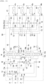
- FIG. 2 is a cycle diagram showing the configuration of an air conditioning apparatus according to an embodiment of the present disclosure.
- the air conditioning apparatus 1 may include an outdoor unit 10, an indoor unit 50 and a heat exchange device 100 connected to the outdoor unit 10 and the indoor unit 60.
- the indoor unit 60 may include a plurality of indoor units 61, 62, 63, and/or 64.
- the heat exchange device 100 may be provided in an indoor space at a position close to the outdoor unit 10, but embodiments disclosed herein are not limited to a location of the heat exchange device 100.
- the outdoor unit 10 and the heat exchange device 100 may fluidly connected by a first fluid.
- the first fluid may include refrigerant.
- the refrigerant may flow through a refrigerant path of a heat exchanger provided in the heat exchange device 100 and the outdoor unit 10.
- the outdoor unit 10 may include a compressor 11 and an outdoor heat exchanger 15.
- An outdoor fan 16 may be provided at one side of the outdoor heat exchanger 15 to blow outside air toward the outdoor heat exchanger 15, and heat exchange between the outside air and the refrigerant of the outdoor heat exchanger 15 may be performed by driving of the outdoor fan 16.
- the outdoor unit 10 may further include a main expansion valve 18 (EEV).
- EEV main expansion valve 18
- the air conditioning apparatus 1 may further include connection pipes 20, 25 and 27 connecting the outdoor unit 10 with the heat exchange device 100.
- connection pipes 20, 25 and 27 may include a first outdoor-unit connection pipe 20 as a pipe (high-pressure gas pipe), through which high-pressure gaseous refrigerant flows, a second outdoor-unit connection pipe 25 as a pipe (low-pressure gas pipe), through which low-pressure gaseous refrigerant flows, and a third outdoor-unit connection pipe 27 as a liquid pipe, through which liquid refrigerant flows.
- the outdoor unit 10 and the heat exchange device 100 have a "three-pipe” connection structure", and refrigerant may be circulated in the outdoor unit 10 and the heat exchange device 100 by the three connection pipes 20, 25 and 27.
- the heat exchange device 100 and the indoor unit 50 may be fluidly connected by a second fluid.
- the second fluid may include water.
- the water may flow through a water path of the heat exchanger provided in the heat exchange device 100 and the indoor unit 50.
- the heat exchange device 100 may include a plurality of heat exchangers 140, 141, 142 and 143.
- the heat exchanger may include, for example, a plate type heat exchanger.
- the indoor unit 50 may include a plurality of indoor units 61, 62, 63 and 64.
- the number of indoor units 61, 62, 63 and 64 is not limited. In FIG. 1 , for example, the four indoor units 61, 62, 63 and 64 are connected to the heat exchange device 100.
- the plurality of indoor units 61, 62, 63 and 64 may include a first indoor unit 61, a second indoor unit 62, a third indoor unit 63 and a fourth indoor unit 64.
- the air conditioning apparatus 1 may further include pipes 30, 31, 32 and 33 connecting the heat exchange device 100 with the indoor unit 50.
- the pipes 30, 31, 32 and 33 may include the first indoor-unit connection pipe 30 to the fourth indoor-unit connection pipe 33 connecting the heat exchange device 100 with the indoor units 61, 62, 63 and 64.
- Water may be circulated in the heat exchange device 100 and the indoor unit 50 through the indoor-unit connection pipes 30, 31, 32 and 33.
- the number of pipes connecting the heat exchange device 100 with the indoor units may increase.
- the refrigerant circulated in the outdoor unit 10 and the heat exchange device 100 and the water circulated in the heat exchange device 100 and the indoor unit 50 may exchange heat through the heat exchangers 140, 141, 142 and 143 provided in the heat exchange device 100.
- Water cooled or heated through heat exchange may exchange heat with the indoor heat exchangers 61a, 62a, 63a and 64a provided in the indoor unit 50, thereby performing cooling or heating of the indoor space.
- the number of heat exchangers 140, 141, 142 and 143 may be equal to the number of indoor units 61, 62, 63 and 64. Alternatively, two or more indoor units may be connected to one heat exchanger.
- the heat exchange device 100 may include first to fourth heat exchangers 140, 141, 142 and 143 fluidly connected to the indoor units 61, 62, 63 and 64.
- the first to fourth heat exchangers 140, 141, 142 and 143 may be formed in the same structure.
- the heat exchangers 140, 141, 142 and 143 may include, for example, plate type heat exchangers and may be configured to such that water paths and refrigerant paths are alternately stacked.
- the heat exchangers 140, 141, 142 and 143 may include refrigerant paths 140a, 141a, 142a and 143a and water paths 140b, 141b, 142b and 143b.
- the refrigerant paths 140a, 141a, 142a and 143a may be fluidly connected with the outdoor unit 10, and refrigerant discharged from the outdoor unit 10 may flow into the refrigerant paths 140a, 141a, 142a and 143 or the refrigerant which has passed through the refrigerant paths 140a, 141a, 142a and 143a may flow into the outdoor unit 10.
- the water paths 140b, 141b, 142b and 143b may be connected with the indoor units 61, 62, 63 and 64, the water discharged from the indoor units 61, 62, 63 and 64 may flow into the water paths 140b, 141b, 142b and 143b, and the water which has passed through the water paths 140b, 141b, 142b and 143b may flow into the indoor units 61, 62, 63 and 64.
- the heat exchange device 100 includes a first connection pipe 131 connected to the first outdoor-unit connection pipe 20 through a first service valve 21.
- the first connection pipe 131 may extend to the inside of the heat exchange device 100 and may be connected to a first port 120a of a first valve device 120.
- the heat exchange device 100 further includes a third connection pipe 133 connected to the second outdoor-unit connection pipe 25 through a second service valve 26.
- the third connection pipe 133 may extend to the inside of the heat exchange device 100, and may be connected to a third port 120c of the first valve device 120.
- the heat exchange device 100 further includes a fourth connection pipe 134 connected to the third outdoor-unit connection pipe 27 through a third service valve 28.
- the fourth connection pipe 134 may extend to the inside of the heat exchange device 100, and may be connected to the first heat exchanger 140 and the second heat exchanger 141.
- the heat exchange device 100 further includes a seventh connection pipe 137 connected to the third outdoor-unit connection pipe 27 through the third service valve 28.
- the seventh connection pipe 137 may extend to the inside of the heat exchange device 100, and may be connected to the first heat exchanger 140 and the second heat exchanger 141.
- the seventh connection pipe 137 may extend from a third branch part 134a of the fourth connection pipe 134 to be connected to the first heat exchanger 140 and the second heat exchanger 141. That is, the fourth connection pipe 134 and the seventh connection pipe 137 may be branched from a pipe extending from the third service valve 28.
- the first to third outdoor-unit connection pipes 20, 25 and 27 may be connected to the heat exchange device 100 through the first to third service valves 21, 26 and 28, thereby achieving "three-pipe connection between the outdoor unit 10 and the heat exchange device 100.
- the first heat exchanger 140 includes the first refrigerant path 140a and the first water path 140b. One side of the first refrigerant path 140a may be connected to the second connection pipe 132.
- the second connection pipe 132 may extend from a second port 120b of the first valve device 120 to be connected to the first heat exchanger 140 and the second heat exchanger 141.
- the other side of the first refrigerant path 140a may be connected to the fourth connection pipe 134.
- the fourth connection pipe 134 may extend from the third service valve 28 to be connected to the first heat exchanger 140 and the second heat exchanger 141. That is, both sides of the first refrigerant path 140a may be connected to the second connection pipe 132 and the fourth connection pipe 134.
- the second heat exchanger 141 includes the second refrigerant path 141a and the second water path 141b. One side of the second refrigerant path 141a may be connected to the second connection pipe 132.
- the second connection pipe 132 may be branched and connected to the first heat exchanger 140 and the second heat exchanger 141.
- the other side of the second refrigerant path 141a may be connected to the fourth connection pipe 134. Both sides of the second refrigerant path 141a may be connected to the second connection pipe 132 and the fourth connection pipe 134.
- the fourth connection pipe 134 may be branched and connected to the first heat exchanger 140 and the second heat exchanger 141.
- the refrigerant discharged from the outdoor unit 10 may flow into the first refrigerant path 140a and the second refrigerant path 141a through the first connection pipe 131 and the first valve device 120, and the refrigerant which has passed through the first refrigerant path 140a and the second refrigerant path 141a may flow into the outdoor unit 10 through the fourth connection pipe 134.
- the third heat exchanger 142 includes the third refrigerant path 142a and the third water path 142b.
- One side of the third refrigerant path 142a may be connected to a sixth connection pipe 136.
- the sixth connection pipe 136 may extend from a second port 125b of the second valve device 125 to be connected to the third heat exchanger 142 and the fourth heat exchanger 143.
- the other side of the third refrigerant path 142a may be connected to the seventh connection pipe 137.
- the seventh connection pipe 137 may extend from the third service valve 28 to be connected to the third heat exchanger 142 and the fourth heat exchanger 143. That is, both sides of the third refrigerant path 142a may be connected to the sixth connection pipe 136 and the seventh connection pipe 137.
- the fourth heat exchanger 143 includes the fourth refrigerant path 143a and the fourth water path 143b.
- One side of the fourth refrigerant path 143a may be connected to the sixth connection pipe 136.
- the sixth connection pipe 136 may be branched and connected to the third heat exchanger 142 and the fourth heat exchanger 143.
- the other side of the fourth refrigerant path 143a may be connected to the seventh connection pipe 137. Both sides of the fourth refrigerant path 143a may be connected to the sixth connection pipe 136 and the seventh connection pipe 137.
- the seventh connection pipe 137 may be branched and connected to the third heat exchanger 142 and the fourth heat exchanger 143.
- the refrigerant discharged from the outdoor unit 10 may flow into the third refrigerant path 142a and the fourth refrigerant path 143a through the first connection pipe 131 and the second valve device 125, and the refrigerant which has passed through the third refrigerant path 142a and the fourth refrigerant path 143a may flow into the outdoor unit 10 through the seventh connection pipe 137.
- a first branch part 131a is formed in the first connection pipe 131.
- the heat exchange device 100 further includes a fifth connection pipe 135 connected to the first branch part 131a to extend to the second valve device 125.
- the fifth connection pipe 135 may be connected to a first port 125a of the second valve device 125.
- a second branch part 133a is formed in the third connection pipe 133.
- the heat exchange device 100 further includes an eighth connection pipe connected to the second branch part 133a to extend to the second valve device 125.
- the eighth connection pipe 138 may be connected to a third port 125c of the second valve device 125.
- the heat exchange device 100 includes the first valve device 120 and the second valve device 125 for controlling the flow direction of the refrigerant.
- the first valve device 120 and the second valve device 125 include four-way valves or three-way valves.
- the first valve device 120 includes a first port 120a, to which the first connection pipe 131 is connected, a second port 120b, to which the second connection pipe 132 is connected, and a third port 120c, to which and the third connection pipe 133 is connected.
- the fourth port of the first valve device 120 may be closed.
- the second valve device 125 includes a first port 125a, to which the fifth connection pipe 135 is connected, a second port 125b, to which the sixth connection pipe 136 is connected, and a third port 125c, to which the eighth connection pipe 138 is connected.
- the fourth port of the second valve device 125 may be closed.
- the heat exchange device 100 may further include expansion valves 144 and 145 for decompression of the refrigerant.
- the expansion valves 144 and 145 may include electronic expansion valves (EEVs).
- the expansion valves 144 and 145 may decrease the pressure of the refrigerant passing through the expansion valves 144 and 145 by controlling an opening degree. For example, when the EEVs 144 and 145 are completely opened (full-open state), the refrigerant may pass without decompression and, when the opening degree of the expansion valves 144 and 145 decreases, the refrigerant may be decompressed. The degree of decompression of the refrigerant increases as the opening degree decreases.
- the expansion valves 144 and 145 include the first expansion valve 144 mounted in the fourth connection pipe 134.
- the first expansion valve 144 may be mounted at one point of the fourth connection pipe 134 between the third service valve 38 and the first refrigerant path 140a or the second refrigerant path 141a.
- the dedicated operation may be understood as a case where the indoor heat exchangers 61a, 62a, 63a and 64a of the plurality of indoor units 61, 62, 63 and 64 function as evaporators or condensers.
- the plurality of indoor heat exchangers 61a, 62a, 63a and 64a is based on the turned-on heat exchangers rather than the turned-off heat exchangers.
- simultaneous operation in which the operation modes of the plurality of indoor units 61, 62, 63 and 64 are different is referred to as "simultaneous operation".
- the simultaneous operation may be understood as a case where some of the plurality of indoor heat exchangers 61a, 62a, 63a and 64a function as condensers and the other indoor heat exchangers function as evaporators.
- the high-pressure gaseous refrigerant introduced through the first outdoor-unit connection pipe 20 may flow into the first refrigerant path 140a of the first heat exchanger 140 and the second refrigerant path 141a of the second heat exchanger 141, thereby being condensed.
- heating is performed in the first indoor unit 61, the second indoor unit 62 and the third indoor unit 63 connected to the first heat exchanger 140 and the second heat exchanger 141.
- the liquid refrigerant discharged from the first refrigerant path 140a and the second refrigerant path 141a may not be decompressed while passing through the first expansion valve 144.
- Some of the refrigerant which has passed through the first expansion valve 144 may be discharged to the third outdoor-unit connection pipe 27 through the third service valve 28.
- the remaining refrigerant may flow into the seventh connection pipe 137 at a third branch part 134a.
- the expansion valves 144 and 145 may further include the second expansion valve 145 mounted in the seventh connection pipe 137.
- the refrigerant branched at the third branch part 134a and introduced into the seventh connection pipe 137 after passing through the first expansion valve 144 may be decompressed to low pressure while passing through the second expansion valve 145 and may be introduced into the third refrigerant path 142a of the third heat exchanger 142 and the fourth refrigerant path 143a of the fourth heat exchanger 143, thereby being evaporated.
- cooling is performed in the fourth indoor unit 64 connected to the third heat exchanger 142 and the fourth heat exchanger 143.
- the low-pressure gaseous refrigerant discharged from the third refrigerant path 142a and the fourth refrigerant path 143a may be discharged to the second outdoor-unit connection pipe 25 through the sixth connection pipe 136, the second valve device 125, the eighth connection pipe 138 and the third connection pipe 133.
- the heat exchange device 100 may further include a bypass pipe 210 connecting the first connection pipe 131 with the third connection pipe 133.
- the bypass pipe 210 may be understood as a pipe for preventing liquid refrigerant from being accumulated in a high-pressure gas pipe during cooling operation.
- One end of the bypass pipe 210 may be connected to a first bypass branch part 131b of the first connection pipe 131, and the other end thereof may be connected to a second bypass branch part 133b of the third connection pipe 133.
- the first branch part 131a may be formed at a point between the first bypass branch part 131b and the first port 120a of the first valve device 120.
- the first bypass branch part 131b may be formed at a point between the first service valve 21 and the first branch part 131a.
- the second branch part 133a may be formed at a point between the second bypass branch part 133b and the third port 120c of the first valve device 120.
- the second bypass branch part 133b may be formed at a point between the second service valve 26 and the second branch part 133a.
- a bypass valve 212 for controlling opening and closing of the pipe is mounted in the bypass pipe 210.
- the bypass valve 212 may include a two-way valve or a solenoid valve having relatively small pressure loss.
- the bypass pipe 210 may be provided with a strainer 211 for filtering out wastes in the refrigerant flowing through the pipe.
- the strainer 212 may be formed of a metal mesh.
- the strainer 212 may be disposed at a point between the bypass valve 212 and the first bypass branch part 131b.
- the bypass pipe 210 may be further provided with an expansion device 213 for decompression of the refrigerant flowing through the pipe.
- the expansion device 213 may be composed of a capillary tube using a capillary phenomenon.
- the expansion device 213 may be disposed at a point between the bypass valve 212 and the second bypass branch part 133b. Accordingly, the pressure of the refrigerant passing through the expansion device 213 may be lowered.
- the heat exchange device 100 may further include heat exchanger inlet pipes 161a, 161b, 163a and 163b and heat exchanger discharge pipes 162a, 162b, 164a and 164b connected to the water paths 140b, 141b, 142b and 143b of the heat exchangers 140, 141, 142 and 143.
- the first heat exchanger inlet pipe 161a of the first heat exchanger 140 and the second heat exchanger inlet pipe 161b of the second heat exchanger 141 may be branched at a first common inlet pipe 161.
- the first common inlet pipe 161 may be provided with a first pump 151.
- the third heat exchanger inlet pipe 163a of the third heat exchanger 142 and the fourth heat exchanger inlet pipe 163b of the fourth heat exchanger 143 may be branched at a second common inlet pipe 163.
- the second common inlet pipe 163 may be provided with a second pump 152.
- the first heat exchanger discharge pipe 162a of the first heat exchanger 140 and the second heat exchanger discharge pipe 162b of the second heat exchanger 141 may be branched at a first common discharge pipe 162.
- the third heat exchanger discharge pipe 164a of the third heat exchanger 142 and the fourth heat exchanger discharge pipe 164b of the fourth heat exchanger 143 may be branched at a second common discharge pipe 164.
- the first common inlet pipe 161 may be connected with a first coupling pipe 181.
- the second common inlet pipe 163 may be connected with a second coupling pipe 182.
- the first common discharge pipe 162 may be connected with a third coupling pipe 183.
- the second common discharge pipe 164 may be connected with a fourth coupling pipe 184.
- the first coupling pipe 181 may be connected with a first water discharge pipe 171, through which water discharged from the indoor heat exchangers 61a, 62a, 63a and 64a flows.
- the second coupling pipe 182 may be connected with a second water discharge pipe 172, through which water discharged from the indoor heat exchangers 61a, 62a, 63a and 64a flows.
- the first water discharge pipe 171 and the second water discharge pipe 172 may be disposed in parallel and may be connected to the common water discharge pipes 651, 652, 653 and 654 communicating with the indoor heat exchangers 61a, 62a, 63a and 64a.
- the first water discharge pipe 171, the second water discharge pipe 172 and the common water discharge pipes 651, 652, 653 and 654 may be connected by a three-way valve 173, for example.
- the water of the common water discharge pipes 651, 652, 653 and 654 may flow into any one of the first water discharge pipe 171 and the second water discharge pipe 172.
- the common water discharge pipes 651, 652, 653 and 654 may be connected with the discharge pipes of the indoor heat exchangers 61a, 62a, 63a and 64a.
- the third coupling pipe 183 may be connected with first water inlet pipes 165a, 165b, 165c and 165d, through which water to be introduced into the indoor heat exchangers 61a, 62a, 63a and 64a flows.
- the fourth coupling pipe 184 may be connected with a second water inlet pipe 167d, through which water to be introduced into the indoor heat exchangers 61a, 62a, 63a and 64a flows.
- the first water inlet pipes 165a, 165b, 165c and 165d and the second water inlet pipe 167d may be disposed in parallel and may be connected with common inlet pipes 611, 621, 631 and 641 communicating with the indoor heat exchangers 61a, 62a, 63a and 64a.
- the first water inlet pipes 165a, 165b, 165c and 165d may be provided with a first valve 166 and the second water inlet pipe 167d may be provided with a second valve 167.
- first heat exchanger 140 and the second heat exchanger 141 may be referred to as a "first heat exchanger”.
- third heat exchanger 142 and the fourth heat exchanger 143 may be referred to as a "second heat exchanger”.
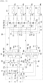
- FIG. 3 is a cycle diagram showing flow of refrigerant and water in a heat exchange device during cooling operation of an air conditioning apparatus according to an embodiment of the present disclosure.
- the air conditioning apparatus 1 when the air conditioning apparatus 1 performs cooling operation (the plurality of indoor units performs cooling operation), the high-pressure liquid refrigerant condensed in the outdoor heat exchanger 15 of the outdoor unit 10 flows into the fourth connection pipe 134 through the third outdoor-unit connection pipe 27, and some refrigerant is branched at the third branch part 134a to flow into the seventh connection pipe 137.
- the cooling operation of the air conditioning apparatus 1 or indoor units means an operation in which indoor units supply air having a lower temperature than the room temperature into indoor spaces.
- the refrigerant of the fourth connection pipe 134 is decompressed in the first expansion valve 144, and is introduced into the first refrigerant path 140a of the first heat exchanger 140 and the second refrigerant path 141a of the second heat exchanger 141 to exchange heat with the first water path 140b and the second water path 141b.
- the refrigerant of the first refrigerant path 140a and the second refrigerant path 141a may be evaporated and the water of the first water path 140b and the second water path 141b may be cooled.
- the cooled water may flow into the first indoor heat exchanger 61a and the second indoor heat exchanger 62a, thereby performing cooling.
- the refrigerant of the seventh connection pipe 137 is decompressed in the second expansion valve 145, and is introduced into the third refrigerant path 142a of the third heat exchanger 142 and the fourth refrigerant path 143a of the fourth heat exchanger 143 to exchange heat with the third water path 142b and the fourth water path 143b.
- the refrigerant of the third refrigerant path 142a and the fourth refrigerant path 143a may be evaporated, and the water of the third water path 142b and the fourth water path 143b may be cooled.
- the cooled water may flow into the third indoor heat exchanger 63a and the fourth indoor heat exchanger 64a, thereby performing cooling.
- the heat exchangers 140, 141, 142 and 143 function as "evaporators" for evaporating low-pressure 2-phase refrigerant.
- the length of the evaporated refrigerant path may be short and the number of paths may increase. Accordingly, it is possible to improve the performance of the refrigerant cycle by preventing evaporation pressure from decreasing.
- the refrigerant discharged from the first heat exchanger 140 and the second heat exchanger 141 may be introduced into the first valve device 120 through the second port 120b and discharged through the third port 120c.
- the refrigerant discharged from the first valve device 120 may flow into the third connection pipe 133 and flow into the outdoor unit 10 through the first outdoor-unit connection pipe 25.
- the refrigerant discharged from the third heat exchanger 142 and the fourth heat exchanger 143 may be introduced into the second valve device 125 through the second port 125b and discharged through the third port 125c.
- the refrigerant discharged from the second valve device 125 may flow into the eighth connection pipe 138 and flow (join) into the third connection pipe 133.
- the refrigerant flowing into the third connection pipe 133 may flow into the outdoor unit 10 through the first outdoor connection pipe 25.
- the refrigerant flowing into the outdoor unit 10 may be sucked into the compressor 11.
- the bypass valve 212 mounted in the bypass pipe 210 is opened.
- the refrigerant condensed in the outdoor unit 10 may flow into a liquid pipe to be evaporated in the heat exchangers 140, 141, 142 and 143, and the evaporated refrigerant may flow into the outdoor unit 10 through the low-pressure gas pipe.
- the refrigerant of the high-pressure gas pipe stay in the pipe and, when this state is maintained for a long time, the liquid refrigerant in the pipe is accumulated.
- the amount of refrigerant circulated in the system may decrease and cycle stability may deteriorate.
- the bypass valve 212 may be opened, and the liquid refrigerant accumulated in the first connection pipe 131 which is a high-pressure gas pipe may flow into the third connection pipe 133 which is the low-pressure gas pipe through the bypass pipe 210 by a pressure difference.
- the wastes in the liquid refrigerant of the first connection pipe 131 are filtered out by the strainer 211, and the liquid refrigerant may be decompressed through the expansion device 213.
- the bypass valve 212 it is possible to prevent a phenomenon wherein the refrigerant is accumulated in the high-pressure gas pipe. Such a refrigerant cycle may be circulated.
- the water flowing through the water paths 140b, 141b, 142b and 143b of the heat exchangers 140, 141, 142 and 143 may be cooled by heat exchange with the refrigerant and the cooled water may be supplied to the indoor heat exchangers 61a, 62a, 63a and 64a, thereby performing cooling.
- the water discharged to the first common discharge pipe 162 may flow into the first indoor heat exchanger 61a and the second indoor heat exchanger 62a.
- the water discharged to the second common discharge pipe 164 may flow into the third indoor heat exchanger 63a and the fourth indoor heat exchanger 64a.
- the water discharged to the first common discharge pipe 162 may flow into the first indoor heat exchanger 61a and the second indoor heat exchanger 62a through the first water inlet pipes 165a and 165b.
- the water discharged to the second common discharge pipe 164 may flow into the third indoor heat exchanger 63a and the fourth indoor heat exchanger 64a through the second water inlet pipe 167d.
- the water flowing through the indoor heat exchangers 61a, 62a, 63a and 64a may exchange heat with inside air blown to the indoor heat exchangers.
- the water flowing through the first and second indoor heat exchangers 61a and 62a may flow toward the first common inlet pipe 161.
- the water flowing through the first and second indoor heat exchangers 61a and 62a may flow into the first common inlet pipe 161 after flowing along the first water discharge pipe 171.
- the water flowing through the third and fourth indoor heat exchangers 63a and 64a may flow toward the second common inlet pipe 163.
- the water flowing through the third and fourth indoor heat exchangers 63a and 64a may flow into the second common inlet pipe 163 after flowing along the second water discharge pipe 172.
- the outdoor unit operates for the cooling operation of the indoor unit, and operation in which all the plurality of indoor units performs cooling operation may be referred to as "cooling-dedicated operation”.
- FIG. 4 is a cycle diagram showing flow of refrigerant and water in a heat exchange device when some of indoor units according to an embodiment of the present disclosure perform cooling operation and the other indoor units perform heating operation.
- the outdoor unit may operate for cooling operation of the indoor unit, some of the plurality of indoor units may perform cooling operation and the other indoor units may perform heating operation. That is, simultaneous operation in which the operation modes of the plurality of indoor units are different may be performed.
- some of the plurality of heat exchangers may function as evaporators and the other heat exchangers may function as condensers.
- the first to third indoor units 61, 62 and 63 perform cooling operation and the fourth indoor unit 64 performs heating operation.
- the first and second heat exchangers 140 and 141 may function as evaporators and the third and fourth heat exchangers 142 and 143 may function as condensers.
- the air conditioning apparatus 1 when the air conditioning apparatus 1 performs simultaneous operation (when some of the plurality of indoor units perform cooling operation and the other indoor units perform heating operation), the high-pressure liquid refrigerant condensed in the outdoor heat exchanger 15 of the outdoor unit 10 flows into the fourth connection pipe 134 through the third outdoor-unit connection pipe 27.
- the refrigerant of the fourth connection pipe 134 is decompressed in the first expansion valve 144 and introduced into the first refrigerant path 140a of the first heat exchanger 140 and the second refrigerant path 141a of the second heat exchanger 141 to exchange heat with the first water path 140b and the second water path 141b.
- the refrigerant of the first refrigerant path 140a and the second refrigerant path 141a may be evaporated, and the water of the first water path 140b and the second water path 141b may be cooled.
- the cooled water may flow into the first indoor heat exchanger 61a and the second indoor heat exchanger 62a, thereby performing cooling.
- first heat exchanger 140 and the second heat exchanger 141 function as "evaporators" for evaporating low-pressure 2-phase refrigerant.
- the refrigerant discharged from the first heat exchanger 140 and the second heat exchanger 141 may be introduced into the first valve device 120 through the second port 120b, and discharged through the third port 120c.
- the refrigerant discharged from the first valve device 120 may flow into the third connection pipe 133, and flow into the outdoor unit 10 through the first outdoor-unit connection pipe 25.
- the high-pressure gaseous refrigerant compressed in the compressor 11 of the outdoor unit 10 flow into the first connection pipe 131 through the first outdoor-unit connection pipe 20.
- the refrigerant of the first connection pipe 131 is branched to the fifth connection pipe 135 at the first branch part 131a and introduced into the second valve device 125 through the first port 125a.
- the refrigerant discharged from the second port 125b of the second valve device 125 flows through the sixth connection pipe 136 and flows into the third refrigerant path 142a of the third heat exchanger 142 and the fourth refrigerant path 143a of the fourth heat exchanger 143, thereby exchanging heat with the third water path 142b and the fourth water path 143b.
- the refrigerant of the third refrigerant path 142a and the fourth refrigerant path 143a may be condensed, and the water of the third water path 142b and the fourth water path 143b may be heated.
- the heated water may flow into the third indoor heat exchanger 63a and the fourth indoor heat exchanger 64a, thereby performing heating.
- the third heat exchanger 142 and the fourth heat exchanger 143 functions as "condensers" for condensing high-pressure gaseous refrigerant.
- the refrigerant discharged from the third heat exchanger 142 and the fourth heat exchanger 143 is combined with the liquid refrigerant flowing through the third outdoor-unit connection pipe 27 after passing through the second expansion valve 145.
- the refrigerant discharged from the third heat exchanger 142 and the fourth heat exchanger 143 may pass through the second expansion valve 145 without decompression.
- the water flowing through the water paths 140b and 141b of the first and second heat exchangers 140 and 141 may be cooled by heat exchange with the refrigerant and the cooled water may be supplied to the first to third indoor heat exchangers 61a, 62a and 63a, thereby performing cooling.
- the water flowing through the water paths 142b and 143b of the third and fourth heat exchangers 142 and 143 may be heated by heat exchange with the refrigerant and the heated water may be supplied to the fourth indoor heat exchanger 64a, thereby performing heating.
- the water discharged to the first common discharge pipe 162 may flow into the first to third indoor heat exchangers 61a, 62a and 63a.
- the water discharged to the second common discharge pipe 164 may flow into the fourth indoor heat exchanger 64a.
- the water discharged to the first common discharge pipe 162 may flow into the first indoor heat exchanger 61a, the second indoor heat exchanger 62a and the third indoor heat exchanger 63a through the first water inlet pipes 165a, 165b and 165c.
- the water discharged to the second common discharge pipe 164 may flow into the fourth indoor heat exchanger 64a through the second water inlet pipe 167d.
- the water flowing through the indoor heat exchangers 61a, 62a, 63a and 64a may exchange heat with inside air blown to the indoor heat exchangers.
- the water flowing through the first to third indoor heat exchangers 61a, 62a and 63a may flow toward the first common inlet pipe 161.
- the water flowing through the first to third indoor heat exchangers 61a, 62a and 63a may flow into the first common inlet pipe 161 after flowing along the first water discharge pipe 171.
- the water flowing through the fourth indoor heat exchanger 64a may flow toward the second common inlet pipe 163.
- the water flowing through the fourth indoor heat exchanger 64a may flow into the second common inlet pipe 163 after flowing along the second water discharge pipe 172.
- main cooling operation operation in which the outdoor unit operates for cooling operation of the indoor unit, some of the plurality of indoor units perform cooling operation and the other indoor units perform heating operation.
- FIG. 5 is a cycle diagram showing flow of refrigerant and water in a heat exchange device during heating operation of an air conditioning apparatus according to an embodiment of the present disclosure.
- the air conditioning apparatus 1 when the air conditioning apparatus 1 performs heating-dedicated operation (when the plurality of indoor units performs heating operation), the high-pressure gaseous refrigerant compressed in the compressor 10 of the outdoor unit 10 flows into the first connection pipe 131 through the first outdoor-unit connection pipe 20, and some refrigerant is branched at the first branch part 134a and introduced into the fifth connection pipe 135.
- the heating-dedicated or heating operation of the air conditioning apparatus 1 or indoor units means an operation in which indoor units supply air having a higher temperature than the room temperature into indoor spaces.
- the refrigerant of the first connection pipe 131 may flow into the first valve device 120 through the first port 120a, and the refrigerant of the fifth connection pipe 135 may flow into the second valve device 125 through the first port 125a.
- the refrigerant flowing into the first valve device 120 is discharged through the second port 120b and introduced into the first refrigerant path 140a of the first heat exchanger 140 and the second refrigerant path 141a of the second heat exchanger 141, thereby exchanging heat with the first water path 140b and the second water path 141b.
- the refrigerant flowing into the second valve device 125 is discharged through the second port 125b and introduced into the third refrigerant path 142a of the third heat exchanger 142 and the fourth refrigerant path of the fourth heat exchanger 143, thereby exchanging heat with the third water path 142b and the fourth water path 143b.
- the refrigerant of the first to fourth refrigerant paths 140a, 141a, 142a and 143a may be condensed, and the water of the first to fourth water paths 140b, 141b, 142b and 143b may be heated.
- the heated water may flow into the first to fourth indoor heat exchangers 61a, 62a, 63a and 64a, thereby performing heating.
- the heat exchangers 140, 141, 142 and 143 functions as “condensers” for compressing high-pressure gaseous refrigerant.
- the refrigerant discharged from the first heat exchanger 140 and the second heat exchanger 141 is decompressed in the first expansion valve 144, and introduced into the fourth connection pipe 134.
- the refrigerant of the fourth connection pipe 134 may flow into the outdoor unit 10 through the third outdoor-unit connection pipe 27.
- the refrigerant discharged from the third heat exchanger 142 and the fourth heat exchanger 143 is decompressed in the second expansion valve 145 and introduced into the seventh connection pipe 137.
- the refrigerant of the seventh connection pipe 137 may flow into the outdoor unit 10 through the third outdoor-unit connection pipe 27.
- the refrigerant flowing into the outdoor unit 10 may be evaporated in the outdoor heat exchanger 15 and sucked into the compressor 11.
- the water flowing through the water paths 140b, 141b, 142b and 143b of the heat exchangers 140, 141, 142 and 143 may be heated by heat exchange with the refrigerant, and the heated water may be supplied to the indoor heat exchangers 61a, 62a, 63a and 64a, thereby performing heating.
- the water discharged to the first common discharge pipe 162 may flow into the first indoor heat exchanger 61a and the second indoor heat exchanger 62a.
- the water discharged to the second common discharge pipe 164 may flow into the third indoor heat exchanger 63a and the fourth indoor heat exchanger 64a.
- the water discharged to the first common discharge pipe 162 may flow into the first indoor heat exchanger 61a and the second indoor heat exchanger 62a through the first water inlet pipes 165 and 165b.
- the water discharged to the second common discharge pipe 164 may flow into the third indoor heat exchanger 63a and the fourth indoor heat exchanger 64a through the second water inlet pipe 167d.
- the water flowing through the indoor heat exchangers 61a, 62a, 63a and 64a may exchange heat with the inside air blown to the indoor heat exchangers.
- the water flowing through the first and second indoor heat exchangers 61a and 62a may flow toward the first common inlet pipe 161.
- the water flowing through the first and second indoor heat exchangers 61a and 62a may flow into the first common inlet pipe 161 after flowing along the first water discharge pipe 171.
- the water flowing through the third and fourth indoor heat exchangers 63a and 64a may flow toward the second common inlet pipe 163.
- the water flowing through the third and fourth indoor heat exchangers 63a and 64a may flow into the second common inlet pipe 163 after flowing along the second water discharge pipe 172.
- heating-dedicated operation operation in which the outdoor unit operates for heating operation of the indoor unit and all the plurality of indoor units performs heating operation.
- FIG. 6 is a cycle diagram showing flow of refrigerant and water in a heat exchange device when some of indoor units according to an embodiment of the present disclosure perform heating operation and the other indoor units perform cooling operation.
- the outdoor unit operates for heating operation of the indoor unit, some of the plurality of indoor units performs heating operation and the other indoor units perform cooling operation. That is, simultaneous operation in which the operation modes of the plurality of indoor units are different may be performed.
- some of the plurality of heat exchangers may function as condensers and the other heat exchangers may function as evaporators.
- the first to third indoor units 61, 62 and 63 perform heating operation and the fourth indoor unit 64 performs cooling operation.
- the first and second heat exchangers 140 and 141 may function as condensers and the third and fourth heat exchangers 142 and 143 may function as evaporators.
- the air conditioning apparatus 1 when the air conditioning apparatus 1 performs simultaneous operation (when some of the plurality of indoor units perform heating operation and the other indoor units perform cooling operation), the high-pressure gaseous refrigerant compressed in the compressor of the outdoor unit 10 flows into the first connection pipe 131 through the first outdoor-unit connection pipe 20.
- the refrigerant of the first connection pipe 131 flows into the first valve device 120 through the first port 120a.
- the refrigerant flowing into the first valve device 120 is discharged through the second port 120b and introduced into the first refrigerant path 140a of the first heat exchanger 140 and the second refrigerant path 141a of the second heat exchanger 141, thereby exchanging heat with the first water path 140b and the second water path 141b.
- the refrigerant of the first and second refrigerant paths 140a and 141a may be condensed and the water of the first and second water paths 140b and 141b may be heated.
- the heated water may flow into the first to third indoor heat exchangers 61a, 62a and 63a, thereby performing heating.
- the first to third heat exchangers 140, 141 and 142 function as “condensers" for compressing the high-pressure gaseous refrigerant.
- the refrigerant discharged from the first heat exchanger 140 and the second heat exchanger 141 passes through the first expansion valve 144 and flows into the fourth connection pipe 134.
- the refrigerant of the fourth connection pipe 134 may flow into the outdoor unit 10 through the third outdoor-unit connection pipe 27.
- the refrigerant flowing into the outdoor unit 10 may be evaporated in the outdoor heat exchanger 15 and then sucked into the compressor 11.
- the refrigerant passing through the fourth connection pipe 134 flows into the seventh connection pipe 137.
- the refrigerant of the seventh connection pipe 137 is decompressed in the second expansion valve 145 and introduced into the third refrigerant path 142a of the third heat exchanger 142 and the fourth refrigerant path 143a of the fourth heat exchanger 143, thereby exchanging heat with the third water path 142b and the fourth water path 143b.
- the refrigerant of the third and fourth refrigerant paths 142a and 143a may be evaporated, and the water of the third and fourth water paths 142b and 143b may be cooled.
- the cooled water may flow into the fourth indoor heat exchanger 64a, thereby performing cooling.
- the fourth heat exchanger 143 functions as an "evaporator" for evaporating low-pressure 2-phase refrigerant.
- the refrigerant discharged from the third heat exchanger 142 and the fourth heat exchanger 143 flows into the second valve device 125 through the second port 125b.
- the refrigerant discharged through the third port 125c of the second valve device 125 flows into the eighth connection pipe 138.
- the refrigerant of the eighth connection pipe 138 may flow into the outdoor unit 10 through the second outdoor-unit connection pipe 25.
- the refrigerant flowing into the outdoor unit 10 may be sucked into the compressor 11.
- the water flowing through the water paths 140b and 141b of the first and second heat exchangers 140 and 141 may be heated by heat exchange with the refrigerant and the heated water may be supplied to the first to third indoor heat exchangers 61a, 62a and 63a, thereby performing heating.
- the water flowing through the water paths 142b and 143b of the third and fourth heat exchangers 142 and 143 may be cooled by heat exchange with the refrigerant, and the cooled water may be supplied to the fourth indoor heat exchanger 64a, thereby performing cooling.
- the water discharged to the first common discharge pipe 162 may flow into the first to third indoor heat exchangers 61a, 62a and 63a.
- the water discharged to the second common discharge pipe 164 may flow into the fourth indoor heat exchanger 64a.
- the water discharged to the first common discharge pipe 162 may flow into the first indoor heat exchanger 61a, the second indoor heat exchanger 62a and the third indoor heat exchanger 63a through the first water inlet pipes 165a, 165b and 165c.
- the water discharged to the second common discharge pipe 164 may flow into the fourth indoor heat exchanger 64a through the second water inlet pipe 167d.
- the water flowing through the indoor heat exchangers 61a, 62a, 63a and 64a may exchange heat with inside air blown to the indoor heat exchangers.
- the water flowing through the first to third indoor heat exchangers 61a, 62a and 63a may flow toward the first common inlet pipe 161.
- the water flowing through the first to third indoor heat exchangers 61a, 62a and 63a may flow into the first common inlet pipe 161 after flowing along the first water discharge pipe 171.
- the water flowing through the fourth indoor heat exchanger 64a may flow toward the second common inlet pipe 163.
- the water flowing through the fourth indoor heat exchanger 64a may flow into the second common inlet pipe 163 after flowing along the second water discharge pipe 172.
- main heating operation operation in which the outdoor unit operates for heating operation of the indoor unit, some of the plurality of indoor units perform heating operation and the other indoor units perform cooling operation.
- the air conditioning apparatus according to the embodiment of the present disclosure having the above-described configuration have the following effects.
- bypassing of the liquid refrigerant, which is accumulated in the high-pressure gas pipe, to the low-pressure gas pipe may be possible. Then, the amount of refrigerant circulated in the cycle is sufficiently maintained, thereby improving air conditioning performance.
- the refrigerant is branched and introduced into the plurality of heat exchangers. Therefore, the number of refrigerant paths increases and the length of the refrigerant paths decreases (parallel connection of the heat exchangers), thereby preventing evaporation pressure from being lowered.
- the refrigerant sequentially passes through the plurality of heat exchangers. Therefore, the length of the refrigerant paths increases and the number of refrigerant paths decreases (series connection of the heat exchangers), thereby improving condensing performance of the heat exchangers.
- cooling operation and heating operation may be simultaneously performed, some indoor units may perform heating operation and the other indoor units may perform cooling operation.
Landscapes
- Engineering & Computer Science (AREA)
- Mechanical Engineering (AREA)
- General Engineering & Computer Science (AREA)
- Physics & Mathematics (AREA)
- Thermal Sciences (AREA)
- Compression-Type Refrigeration Machines With Reversible Cycles (AREA)
- Air Conditioning Control Device (AREA)
- Life Sciences & Earth Sciences (AREA)
- Sustainable Development (AREA)
- Chemical & Material Sciences (AREA)
- Combustion & Propulsion (AREA)
- Other Air-Conditioning Systems (AREA)
Description
- The present invention relates to an air conditioning apparatus.
- An air conditioning apparatus refers to an apparatus for maintaining the air of a predetermined space in a suitable condition according to usage and purposes thereof. In general, the air conditioning apparatus includes a compressor, a condenser, an expansion device and an evaporator, and may cool or heat the predetermined space by performing a refrigeration cycle for performing compression, condensing, expansion and evaporation of refrigerant.
- The predetermined space may be changed according to a place where the air conditioning apparatus is used. For example, the predetermined space may be a home or office space.
- When the air conditioning apparatus performs cooling operation, an outdoor heat exchanger provided in an outdoor unit functions as a condenser and an indoor heat exchanger provided in an indoor unit functions as an evaporator. On the other hand, when the air conditioning apparatus performs heating operation, the indoor heat exchanger functions as a condenser and the outdoor heat exchanger functions as an evaporator.
- In recent years, the type of refrigerant used in the air conditioning apparatus has been limited and the amount of used refrigerant has been reduced, according to an environmental regulation policy.
- In order to reduce the amount of used refrigerant, technology for performing cooling or heating by performing heat exchange between refrigerant and predetermined fluid has been proposed. For example, the predetermined fluid may include water.
-
US Patent Publication No. 2015-0176864 (publication date: June 25, 2015 ) which is a prior document discloses an air conditioning apparatus for performing cooling or heating through heat exchange between refrigerant and water. - The air conditioning apparatus disclosed in the prior document includes a plurality of heat exchangers for heat exchange between refrigerant and water and two valve devices connected to a refrigerant path such that each heat exchanger functions as an evaporator or a condenser. That is, the conventional air conditioning apparatus may determine the operation mode of the heat exchanger through control of the valve device.
- In addition, the conventional air conditioning apparatus further includes three pipes connecting an outdoor unit and a heat exchange device. The three pipes include a high-pressure gas pipe, through which high-pressure gaseous refrigerant flows, a low-pressure gas pipe, through which low-pressure gaseous refrigerant flows, and a liquid pipe, through which liquid flows.
- However, when cooling operation is performed in a structure having three pipes, refrigerant condensed in the outdoor unit may be introduced into the liquid pipe and evaporated in the heat exchanger, and the evaporated refrigerant may flow through the low-pressure gas pipe and flow into the outdoor unit. At this time, the refrigerant of the high-pressure gas pipe stays in the pipe and, if this state is maintained for a long time, the liquid refrigerant is accumulated in the pipe. When the liquid refrigerant is accumulated in the pipe, the amount of refrigerant circulated in the system may decrease and thus cycle stability may deteriorate.
- In addition, in the case of a water pipe, a phenomenon wherein a flow rate is insufficient may occur due to excessive use of a three-way valve having large pressure loss and it may be difficult to control a water pipe valve during dedicated operation.
- (Patent Document 1) Publication No. (Publication date):
US 2015-0176864 (June 25, 2015 ). -
US 2012/118005 A1 relates to an air-conditioning apparatus configured such that heat medium pipes have a larger inner cross-sectional area per unit capacity than that of refrigerant pipes. -
EP 2 963 358 A1 relates to an air-conditioner in which a plurality of heat medium flow switching devices respectively corresponding to a plurality of use-side heat exchangers are entirely or partially integrated. -
EP 2 495 514 A1 relates to an air-conditioning apparatus capable of supplying heating energy, cooling energy, or both the heating energy and the cooling energy generated in a heat source device for a plurality of air conditioning loads. - An object of the present invention devised to solve the problem lies in an air conditioning apparatus for preventing liquid refrigerant from being accumulated in a high-pressure gas pipe during cooling operation of an indoor unit. An air conditioning apparatus according to claim 1 is therefore provided.
- Another object of the present invention devised to solve the problem lies in an air conditioning apparatus for preventing evaporation pressure from being lowered when a plurality of heat exchangers provided in a heat exchange device functions as evaporators during cooling operation.
- Another object of the present invention devised to solve the problem lies in an air conditioning apparatus for improving condensing performance when a plurality of heat exchangers functions as condensers during heating operation.
- Another object of the present invention devised to solve the problem lies in an air conditioning apparatus capable of simultaneously performing cooling operation and heating operation by connecting an outdoor unit with a heat exchange device through three pipes.
- Another object of the present invention devised to solve the problem lies in an air conditioning apparatus capable of preventing a phenomenon wherein a flow rate is insufficient due to pressure loss and simplifying valve control, by minimizing use of a three-way valve used in a water pipe.
- An air conditioning apparatus according to the embodiment of the present invention includes a bypass pipe connecting a first bypass branch part of a first connection pipe, through which high-pressure refrigerant flows, with a second bypass branch part of a third connection pipe, through which low-pressure refrigerant flows, to allow bypassing of high-pressure refrigerant in the first connection pipe to the third connection pipe, and a bypass valve mounted in the bypass pipe.
- In particular, during cooling operation of an indoor unit, the bypass valve is opened to allow bypassing of high-pressure refrigerant of the first connection pipe to the third connection pipe, thereby preventing liquid refrigerant from being accumulated in a high-pressure gas pipe and preventing a refrigerant shortage phenomenon of a cycle.
- According to the invention, the air conditioning apparatus includes an outdoor unit including a compressor and an outdoor heat exchanger and configured to circulate refrigerant, an indoor unit configured to circulate water, first and second heat exchangers configured to perform heat exchange between the refrigerant and the water, a first valve device connected to the first heat exchanger and configured to control a flow direction of the refrigerant, and a second valve device connected to the second heat exchanger and configured to control a flow direction of the refrigerant.
- The air conditioning apparatus includes a first connection pipe connected to a first port of the first valve device such that high-pressure refrigerant compressed in the compressor flows therethrough, and forming a first bypass branch part, a second connection pipe connected to a second port of the first valve device and connected to the first heat exchanger, and a third connection pipe connected to a third port of the first valve device such that evaporated low-pressure refrigerant flows therethrough, and forming a second bypass branch part.
- In addition, during heating operation of the indoor unit, the bypass valve may be closed to limit bypassing of the refrigerant of the first connection pipe to the third connection pipe.
- In addition, a plurality of indoor units may be provided, and, when the outdoor unit operates for cooling operation of the indoor units, some of the plurality of indoor units perform cooling operation and the other indoor units perform heating operation, the bypass valve may be closed to limit bypassing of the refrigerant of the first connection pipe to the third connection pipe.
- In addition, a plurality of indoor units may be provided, and, when the outdoor unit operates for heating operation of the indoor units, some of the plurality of indoor units perform heating operation and the other indoor units perform cooling operation, the bypass valve may be closed to limit bypassing of the refrigerant of the first connection pipe to the third connection pipe.
- The air conditioning apparatus may further include a strainer provided in the bypass pipe and located at a point between the first bypass branch part and the bypass valve to filter out wastes in the refrigerant.
- The air conditioning apparatus includes an expansion device provided in the bypass pipe and located at a point between the second bypass branch part and the bypass valve to decompress the refrigerant.
- The air conditioning apparatus further includes a fourth connection pipe connected to the first heat exchanger and provided with a first expansion valve, and, during cooling operation of the indoor unit, refrigerant condensed in the outdoor unit is evaporated in the first heat exchanger through the fourth connection pipe.
- The air conditioning apparatus further includes a first branch part formed in the first connection pipe, and a fifth connection pipe connected to the first branch part and connected to the first port of the second valve device.
- At this time, the first branch part may be formed at a point between the first bypass branch part and the first port of the first valve device.
- The air conditioning apparatus may further include a second branch part formed in the third connection pipe, and an eighth connection pipe connected to the second branch part and connected to the third port of the second valve device.
- At this time, the second branch part may be formed at a point between the second bypass branch part and the third port of the first valve device.
- In addition, the air conditioning apparatus may further include a sixth connection pipe connected to the second port of the second valve device and connected to the second heat exchanger, and a seventh connection pipe connected to the second heat exchanger and coupled to a third branch part of the fourth connection pipe. The seventh connection pipe may be provided with a second expansion valve.
-
-
FIG. 1 is a schematic view showing an air conditioning apparatus of an embodiment of the present invention. -
FIG. 2 is a cycle diagram showing the configuration of an air conditioning apparatus according to an embodiment of the present invention. -
FIG. 3 is a cycle diagram showing flow of refrigerant and water in a heat exchange device during cooling operation of an air conditioning apparatus according to an embodiment of the present invention. -
FIG. 4 is a cycle diagram showing flow of refrigerant and water in a heat exchange device when some of indoor units according to an embodiment of the present disclosure perform cooling operation and the other indoor units perform heating operation. -
FIG. 5 is a cycle diagram showing flow of refrigerant and water in a heat exchange device during heating operation of an air conditioning apparatus according to an embodiment of the present invention. -
FIG. 6 is a cycle diagram showing flow of refrigerant and water in a heat exchange device when some of indoor units according to an embodiment of the present disclosure perform heating operation and the other indoor units perform cooling operation. - Reference will now be made in detail to the embodiments of the present invention, examples of which are illustrated in the accompanying drawings.
- In the following detailed description of the preferred embodiments, reference is made to the accompanying drawings that form a part hereof, and in which is shown by way of illustration specific preferred embodiments in which the invention may be practiced. These embodiments are described in sufficient detail to enable those skilled in the art to practice the invention, and it is understood that other embodiments may be utilized and that logical structural, mechanical, electrical, and chemical changes may be made without departing from the scope of the invention. To avoid detail not necessary to enable those skilled in the art to practice the invention, the description may omit certain information known to those skilled in the art. The following detailed description is, therefore, not to be taken in a limiting sense.
- Also, in the description of embodiments, terms such as first, second, A, B, (a), (b) or the like may be used herein when describing components of the present invention. Each of these terminologies is not used to define an essence, order or sequence of a corresponding component but used merely to distinguish the corresponding component from other component (s) . It should be noted that if it is described in the specification that one component is "connected," "coupled" or "joined" to another component, the former may be directly "connected," "coupled," and "joined" to the latter or "connected", "coupled", and "joined" to the latter via another component.
-
FIG. 1 is a schematic view showing an air conditioning apparatus of an embodiment of the present disclosure.FIG. 2 is a cycle diagram showing the configuration of an air conditioning apparatus according to an embodiment of the present disclosure. - Referring to
FIGS. 1 and2 , the air conditioning apparatus 1 according to the embodiment of the present disclosure may include anoutdoor unit 10, an indoor unit 50 and aheat exchange device 100 connected to theoutdoor unit 10 and theindoor unit 60. Theindoor unit 60 may include a plurality ofindoor units heat exchange device 100 may be provided in an indoor space at a position close to theoutdoor unit 10, but embodiments disclosed herein are not limited to a location of theheat exchange device 100. - The
outdoor unit 10 and theheat exchange device 100 may fluidly connected by a first fluid. For example, the first fluid may include refrigerant. - The refrigerant may flow through a refrigerant path of a heat exchanger provided in the
heat exchange device 100 and theoutdoor unit 10. - The
outdoor unit 10 may include acompressor 11 and anoutdoor heat exchanger 15. - An
outdoor fan 16 may be provided at one side of theoutdoor heat exchanger 15 to blow outside air toward theoutdoor heat exchanger 15, and heat exchange between the outside air and the refrigerant of theoutdoor heat exchanger 15 may be performed by driving of theoutdoor fan 16. - The
outdoor unit 10 may further include a main expansion valve 18 (EEV). - The air conditioning apparatus 1 may further include
connection pipes outdoor unit 10 with theheat exchange device 100. - The
connection pipes unit connection pipe 20 as a pipe (high-pressure gas pipe), through which high-pressure gaseous refrigerant flows, a second outdoor-unit connection pipe 25 as a pipe (low-pressure gas pipe), through which low-pressure gaseous refrigerant flows, and a third outdoor-unit connection pipe 27 as a liquid pipe, through which liquid refrigerant flows. - That is, the
outdoor unit 10 and theheat exchange device 100 have a "three-pipe" connection structure", and refrigerant may be circulated in theoutdoor unit 10 and theheat exchange device 100 by the threeconnection pipes - The
heat exchange device 100 and the indoor unit 50 may be fluidly connected by a second fluid. For example, the second fluid may include water. - The water may flow through a water path of the heat exchanger provided in the
heat exchange device 100 and the indoor unit 50. - The
heat exchange device 100 may include a plurality ofheat exchangers - The indoor unit 50 may include a plurality of
indoor units - In the present embodiment, the number of
indoor units FIG. 1 , for example, the fourindoor units heat exchange device 100. - The plurality of
indoor units indoor unit 61, a secondindoor unit 62, a thirdindoor unit 63 and a fourthindoor unit 64. - The air conditioning apparatus 1 may further include
pipes heat exchange device 100 with the indoor unit 50. - The
pipes unit connection pipe 30 to the fourth indoor-unit connection pipe 33 connecting theheat exchange device 100 with theindoor units - Water may be circulated in the
heat exchange device 100 and the indoor unit 50 through the indoor-unit connection pipes heat exchange device 100 with the indoor units may increase. - According to this configuration, the refrigerant circulated in the
outdoor unit 10 and theheat exchange device 100 and the water circulated in theheat exchange device 100 and the indoor unit 50 may exchange heat through theheat exchangers heat exchange device 100. - Water cooled or heated through heat exchange may exchange heat with the
indoor heat exchangers - The number of
heat exchangers indoor units - Hereinafter, the
heat exchange device 100 will be described in detail with reference to the drawings. - The
heat exchange device 100 may include first tofourth heat exchangers indoor units - The first to
fourth heat exchangers - The
heat exchangers - The
heat exchangers refrigerant paths water paths - The
refrigerant paths outdoor unit 10, and refrigerant discharged from theoutdoor unit 10 may flow into therefrigerant paths refrigerant paths outdoor unit 10. - The
water paths indoor units indoor units water paths water paths indoor units - The
heat exchange device 100 includes afirst connection pipe 131 connected to the first outdoor-unit connection pipe 20 through afirst service valve 21. Thefirst connection pipe 131 may extend to the inside of theheat exchange device 100 and may be connected to afirst port 120a of afirst valve device 120. - The
heat exchange device 100 further includes athird connection pipe 133 connected to the second outdoor-unit connection pipe 25 through asecond service valve 26. Thethird connection pipe 133 may extend to the inside of theheat exchange device 100, and may be connected to athird port 120c of thefirst valve device 120. - The
heat exchange device 100 further includes afourth connection pipe 134 connected to the third outdoor-unit connection pipe 27 through athird service valve 28. Thefourth connection pipe 134 may extend to the inside of theheat exchange device 100, and may be connected to thefirst heat exchanger 140 and thesecond heat exchanger 141. - The
heat exchange device 100 further includes aseventh connection pipe 137 connected to the third outdoor-unit connection pipe 27 through thethird service valve 28. Theseventh connection pipe 137 may extend to the inside of theheat exchange device 100, and may be connected to thefirst heat exchanger 140 and thesecond heat exchanger 141. - The
seventh connection pipe 137 may extend from athird branch part 134a of thefourth connection pipe 134 to be connected to thefirst heat exchanger 140 and thesecond heat exchanger 141. That is, thefourth connection pipe 134 and theseventh connection pipe 137 may be branched from a pipe extending from thethird service valve 28. - The first to third outdoor-
unit connection pipes heat exchange device 100 through the first tothird service valves outdoor unit 10 and theheat exchange device 100. - The
first heat exchanger 140 includes the firstrefrigerant path 140a and thefirst water path 140b. One side of the firstrefrigerant path 140a may be connected to thesecond connection pipe 132. Thesecond connection pipe 132 may extend from asecond port 120b of thefirst valve device 120 to be connected to thefirst heat exchanger 140 and thesecond heat exchanger 141. - The other side of the first
refrigerant path 140a may be connected to thefourth connection pipe 134. Thefourth connection pipe 134 may extend from thethird service valve 28 to be connected to thefirst heat exchanger 140 and thesecond heat exchanger 141. That is, both sides of the firstrefrigerant path 140a may be connected to thesecond connection pipe 132 and thefourth connection pipe 134. - The
second heat exchanger 141 includes the secondrefrigerant path 141a and thesecond water path 141b. One side of the secondrefrigerant path 141a may be connected to thesecond connection pipe 132. Thesecond connection pipe 132 may be branched and connected to thefirst heat exchanger 140 and thesecond heat exchanger 141. - The other side of the second
refrigerant path 141a may be connected to thefourth connection pipe 134. Both sides of the secondrefrigerant path 141a may be connected to thesecond connection pipe 132 and thefourth connection pipe 134. Thefourth connection pipe 134 may be branched and connected to thefirst heat exchanger 140 and thesecond heat exchanger 141. - The refrigerant discharged from the
outdoor unit 10 may flow into the firstrefrigerant path 140a and the secondrefrigerant path 141a through thefirst connection pipe 131 and thefirst valve device 120, and the refrigerant which has passed through the firstrefrigerant path 140a and the secondrefrigerant path 141a may flow into theoutdoor unit 10 through thefourth connection pipe 134. - The
third heat exchanger 142 includes the thirdrefrigerant path 142a and thethird water path 142b. One side of the thirdrefrigerant path 142a may be connected to asixth connection pipe 136. Thesixth connection pipe 136 may extend from asecond port 125b of thesecond valve device 125 to be connected to thethird heat exchanger 142 and thefourth heat exchanger 143. - The other side of the third
refrigerant path 142a may be connected to theseventh connection pipe 137. Theseventh connection pipe 137 may extend from thethird service valve 28 to be connected to thethird heat exchanger 142 and thefourth heat exchanger 143. That is, both sides of the thirdrefrigerant path 142a may be connected to thesixth connection pipe 136 and theseventh connection pipe 137. - The
fourth heat exchanger 143 includes the fourthrefrigerant path 143a and thefourth water path 143b. One side of the fourthrefrigerant path 143a may be connected to thesixth connection pipe 136. Thesixth connection pipe 136 may be branched and connected to thethird heat exchanger 142 and thefourth heat exchanger 143. - The other side of the fourth
refrigerant path 143a may be connected to theseventh connection pipe 137. Both sides of the fourthrefrigerant path 143a may be connected to thesixth connection pipe 136 and theseventh connection pipe 137. Theseventh connection pipe 137 may be branched and connected to thethird heat exchanger 142 and thefourth heat exchanger 143. - The refrigerant discharged from the
outdoor unit 10 may flow into the thirdrefrigerant path 142a and the fourthrefrigerant path 143a through thefirst connection pipe 131 and thesecond valve device 125, and the refrigerant which has passed through the thirdrefrigerant path 142a and the fourthrefrigerant path 143a may flow into theoutdoor unit 10 through theseventh connection pipe 137. - A
first branch part 131a is formed in thefirst connection pipe 131. - The
heat exchange device 100 further includes afifth connection pipe 135 connected to thefirst branch part 131a to extend to thesecond valve device 125. Thefifth connection pipe 135 may be connected to afirst port 125a of thesecond valve device 125. - A
second branch part 133a is formed in thethird connection pipe 133. - The
heat exchange device 100 further includes an eighth connection pipe connected to thesecond branch part 133a to extend to thesecond valve device 125. Theeighth connection pipe 138 may be connected to athird port 125c of thesecond valve device 125. - The
heat exchange device 100 includes thefirst valve device 120 and thesecond valve device 125 for controlling the flow direction of the refrigerant. Thefirst valve device 120 and thesecond valve device 125 include four-way valves or three-way valves. Hereinafter, it is assumed that thefirst valve device 120 and thesecond valve device 125 include four-wave valves. - The
first valve device 120 includes afirst port 120a, to which thefirst connection pipe 131 is connected, asecond port 120b, to which thesecond connection pipe 132 is connected, and athird port 120c, to which and thethird connection pipe 133 is connected. The fourth port of thefirst valve device 120 may be closed. - The
second valve device 125 includes afirst port 125a, to which thefifth connection pipe 135 is connected, asecond port 125b, to which thesixth connection pipe 136 is connected, and athird port 125c, to which theeighth connection pipe 138 is connected. The fourth port of thesecond valve device 125 may be closed. - The
heat exchange device 100 may further includeexpansion valves expansion valves - The
expansion valves expansion valves EEVs expansion valves - Specifically, the
expansion valves first expansion valve 144 mounted in thefourth connection pipe 134. Thefirst expansion valve 144 may be mounted at one point of thefourth connection pipe 134 between the third service valve 38 and the firstrefrigerant path 140a or the secondrefrigerant path 141a. - Meanwhile, operation in which the operation modes of the plurality of
indoor units indoor heat exchangers indoor units indoor heat exchangers - In addition, operation in which the operation modes of the plurality of
indoor units indoor heat exchangers - For example, during simultaneous operation of the air conditioning apparatus 1, the high-pressure gaseous refrigerant introduced through the first outdoor-
unit connection pipe 20 may flow into the firstrefrigerant path 140a of thefirst heat exchanger 140 and the secondrefrigerant path 141a of thesecond heat exchanger 141, thereby being condensed. In addition, heating is performed in the firstindoor unit 61, the secondindoor unit 62 and the thirdindoor unit 63 connected to thefirst heat exchanger 140 and thesecond heat exchanger 141. - At this time, the liquid refrigerant discharged from the first
refrigerant path 140a and the secondrefrigerant path 141a may not be decompressed while passing through thefirst expansion valve 144. Some of the refrigerant which has passed through thefirst expansion valve 144 may be discharged to the third outdoor-unit connection pipe 27 through thethird service valve 28. In addition, the remaining refrigerant may flow into theseventh connection pipe 137 at athird branch part 134a. - The
expansion valves second expansion valve 145 mounted in theseventh connection pipe 137. - For example, during the simultaneous operation of the air conditioning apparatus 1, the refrigerant branched at the
third branch part 134a and introduced into theseventh connection pipe 137 after passing through thefirst expansion valve 144 may be decompressed to low pressure while passing through thesecond expansion valve 145 and may be introduced into the thirdrefrigerant path 142a of thethird heat exchanger 142 and the fourthrefrigerant path 143a of thefourth heat exchanger 143, thereby being evaporated. In addition, cooling is performed in the fourthindoor unit 64 connected to thethird heat exchanger 142 and thefourth heat exchanger 143. - At this time, the low-pressure gaseous refrigerant discharged from the third
refrigerant path 142a and the fourthrefrigerant path 143a may be discharged to the second outdoor-unit connection pipe 25 through thesixth connection pipe 136, thesecond valve device 125, theeighth connection pipe 138 and thethird connection pipe 133. - The
heat exchange device 100 may further include abypass pipe 210 connecting thefirst connection pipe 131 with thethird connection pipe 133. - The
bypass pipe 210 may be understood as a pipe for preventing liquid refrigerant from being accumulated in a high-pressure gas pipe during cooling operation. One end of thebypass pipe 210 may be connected to a firstbypass branch part 131b of thefirst connection pipe 131, and the other end thereof may be connected to a secondbypass branch part 133b of thethird connection pipe 133. - Based on the
first connection pipe 131, thefirst branch part 131a may be formed at a point between the firstbypass branch part 131b and thefirst port 120a of thefirst valve device 120. - Based on the
first connection pipe 131, the firstbypass branch part 131b may be formed at a point between thefirst service valve 21 and thefirst branch part 131a. - Based on the
third connection pipe 133, thesecond branch part 133a may be formed at a point between the secondbypass branch part 133b and thethird port 120c of thefirst valve device 120. - Based on the
third connection pipe 131, the secondbypass branch part 133b may be formed at a point between thesecond service valve 26 and thesecond branch part 133a. - A
bypass valve 212 for controlling opening and closing of the pipe is mounted in thebypass pipe 210. For example, thebypass valve 212 may include a two-way valve or a solenoid valve having relatively small pressure loss. - The
bypass pipe 210 may be provided with astrainer 211 for filtering out wastes in the refrigerant flowing through the pipe. For example, thestrainer 212 may be formed of a metal mesh. Thestrainer 212 may be disposed at a point between thebypass valve 212 and the firstbypass branch part 131b. - The
bypass pipe 210 may be further provided with anexpansion device 213 for decompression of the refrigerant flowing through the pipe. For example, theexpansion device 213 may be composed of a capillary tube using a capillary phenomenon. - The
expansion device 213 may be disposed at a point between thebypass valve 212 and the secondbypass branch part 133b. Accordingly, the pressure of the refrigerant passing through theexpansion device 213 may be lowered. - The
heat exchange device 100 may further include heatexchanger inlet pipes exchanger discharge pipes water paths heat exchangers - The first heat
exchanger inlet pipe 161a of thefirst heat exchanger 140 and the second heatexchanger inlet pipe 161b of thesecond heat exchanger 141 may be branched at a firstcommon inlet pipe 161. The firstcommon inlet pipe 161 may be provided with afirst pump 151. - The third heat
exchanger inlet pipe 163a of thethird heat exchanger 142 and the fourth heatexchanger inlet pipe 163b of thefourth heat exchanger 143 may be branched at a secondcommon inlet pipe 163. The secondcommon inlet pipe 163 may be provided with asecond pump 152. - The first heat
exchanger discharge pipe 162a of thefirst heat exchanger 140 and the second heatexchanger discharge pipe 162b of thesecond heat exchanger 141 may be branched at a firstcommon discharge pipe 162. - The third heat
exchanger discharge pipe 164a of thethird heat exchanger 142 and the fourth heatexchanger discharge pipe 164b of thefourth heat exchanger 143 may be branched at a secondcommon discharge pipe 164. - The first
common inlet pipe 161 may be connected with afirst coupling pipe 181. The secondcommon inlet pipe 163 may be connected with asecond coupling pipe 182. - The first
common discharge pipe 162 may be connected with athird coupling pipe 183. The secondcommon discharge pipe 164 may be connected with afourth coupling pipe 184. - The
first coupling pipe 181 may be connected with a firstwater discharge pipe 171, through which water discharged from theindoor heat exchangers - The
second coupling pipe 182 may be connected with a secondwater discharge pipe 172, through which water discharged from theindoor heat exchangers - The first
water discharge pipe 171 and the secondwater discharge pipe 172 may be disposed in parallel and may be connected to the commonwater discharge pipes indoor heat exchangers - The first
water discharge pipe 171, the secondwater discharge pipe 172 and the commonwater discharge pipes way valve 173, for example. - Accordingly, by the three-
way valve 173, the water of the commonwater discharge pipes water discharge pipe 171 and the secondwater discharge pipe 172. - The common
water discharge pipes indoor heat exchangers - The
third coupling pipe 183 may be connected with firstwater inlet pipes indoor heat exchangers - The
fourth coupling pipe 184 may be connected with a secondwater inlet pipe 167d, through which water to be introduced into theindoor heat exchangers - The first
water inlet pipes water inlet pipe 167d may be disposed in parallel and may be connected withcommon inlet pipes indoor heat exchangers - The first
water inlet pipes first valve 166 and the secondwater inlet pipe 167d may be provided with asecond valve 167. - Meanwhile, the
first heat exchanger 140 and thesecond heat exchanger 141 may be referred to as a "first heat exchanger". In addition, thethird heat exchanger 142 and thefourth heat exchanger 143 may be referred to as a "second heat exchanger". -
FIG. 3 is a cycle diagram showing flow of refrigerant and water in a heat exchange device during cooling operation of an air conditioning apparatus according to an embodiment of the present disclosure. - Referring to
FIG. 3 , when the air conditioning apparatus 1 performs cooling operation (the plurality of indoor units performs cooling operation), the high-pressure liquid refrigerant condensed in theoutdoor heat exchanger 15 of theoutdoor unit 10 flows into thefourth connection pipe 134 through the third outdoor-unit connection pipe 27, and some refrigerant is branched at thethird branch part 134a to flow into theseventh connection pipe 137. The cooling operation of the air conditioning apparatus 1 or indoor units means an operation in which indoor units supply air having a lower temperature than the room temperature into indoor spaces. - The refrigerant of the
fourth connection pipe 134 is decompressed in thefirst expansion valve 144, and is introduced into the firstrefrigerant path 140a of thefirst heat exchanger 140 and the secondrefrigerant path 141a of thesecond heat exchanger 141 to exchange heat with thefirst water path 140b and thesecond water path 141b. - By heat exchange, the refrigerant of the first
refrigerant path 140a and the secondrefrigerant path 141a may be evaporated and the water of thefirst water path 140b and thesecond water path 141b may be cooled. The cooled water may flow into the firstindoor heat exchanger 61a and the secondindoor heat exchanger 62a, thereby performing cooling. - The refrigerant of the
seventh connection pipe 137 is decompressed in thesecond expansion valve 145, and is introduced into the thirdrefrigerant path 142a of thethird heat exchanger 142 and the fourthrefrigerant path 143a of thefourth heat exchanger 143 to exchange heat with thethird water path 142b and thefourth water path 143b. - By heat exchange, the refrigerant of the third
refrigerant path 142a and the fourthrefrigerant path 143a may be evaporated, and the water of thethird water path 142b and thefourth water path 143b may be cooled. The cooled water may flow into the thirdindoor heat exchanger 63a and the fourthindoor heat exchanger 64a, thereby performing cooling. - In summary, during the cooling operation of the air conditioning apparatus 1, the
heat exchangers - Since the
heat exchangers - The refrigerant discharged from the
first heat exchanger 140 and thesecond heat exchanger 141 may be introduced into thefirst valve device 120 through thesecond port 120b and discharged through thethird port 120c. The refrigerant discharged from thefirst valve device 120 may flow into thethird connection pipe 133 and flow into theoutdoor unit 10 through the first outdoor-unit connection pipe 25. - The refrigerant discharged from the
third heat exchanger 142 and thefourth heat exchanger 143 may be introduced into thesecond valve device 125 through thesecond port 125b and discharged through thethird port 125c. The refrigerant discharged from thesecond valve device 125 may flow into theeighth connection pipe 138 and flow (join) into thethird connection pipe 133. The refrigerant flowing into thethird connection pipe 133 may flow into theoutdoor unit 10 through the firstoutdoor connection pipe 25. - The refrigerant flowing into the
outdoor unit 10 may be sucked into thecompressor 11. - Meanwhile, when the air conditioning apparatus 1 performs cooling operation, the
bypass valve 212 mounted in thebypass pipe 210 is opened. - Specifically, during the cooling operation of the air conditioning apparatus 1, the refrigerant condensed in the
outdoor unit 10 may flow into a liquid pipe to be evaporated in theheat exchangers outdoor unit 10 through the low-pressure gas pipe. - At this time, the refrigerant of the high-pressure gas pipe stay in the pipe and, when this state is maintained for a long time, the liquid refrigerant in the pipe is accumulated. When the liquid refrigerant in the pipe is accumulated, the amount of refrigerant circulated in the system may decrease and cycle stability may deteriorate.
- However, in the present disclosure, when the air conditioning apparatus 1 performs cooling operation, the
bypass valve 212 may be opened, and the liquid refrigerant accumulated in thefirst connection pipe 131 which is a high-pressure gas pipe may flow into thethird connection pipe 133 which is the low-pressure gas pipe through thebypass pipe 210 by a pressure difference. - At this time, the wastes in the liquid refrigerant of the
first connection pipe 131 are filtered out by thestrainer 211, and the liquid refrigerant may be decompressed through theexpansion device 213. As a result, by opening of thebypass valve 212, it is possible to prevent a phenomenon wherein the refrigerant is accumulated in the high-pressure gas pipe. Such a refrigerant cycle may be circulated. - Meanwhile, the water flowing through the
water paths heat exchangers indoor heat exchangers - In the present embodiment, the water discharged to the first
common discharge pipe 162 may flow into the firstindoor heat exchanger 61a and the secondindoor heat exchanger 62a. In contrast, the water discharged to the secondcommon discharge pipe 164 may flow into the thirdindoor heat exchanger 63a and the fourthindoor heat exchanger 64a. - For example, the water discharged to the first
common discharge pipe 162 may flow into the firstindoor heat exchanger 61a and the secondindoor heat exchanger 62a through the firstwater inlet pipes - In contrast, the water discharged to the second
common discharge pipe 164 may flow into the thirdindoor heat exchanger 63a and the fourthindoor heat exchanger 64a through the secondwater inlet pipe 167d. - The water flowing through the
indoor heat exchangers - Since the water which has exchanged heat with the refrigerant in the
heat exchangers indoor heat exchangers - In the present embodiment, the water flowing through the first and second
indoor heat exchangers common inlet pipe 161. - For example, the water flowing through the first and second
indoor heat exchangers common inlet pipe 161 after flowing along the firstwater discharge pipe 171. - In contrast, the water flowing through the third and fourth
indoor heat exchangers common inlet pipe 163. - For example, the water flowing through the third and fourth
indoor heat exchangers common inlet pipe 163 after flowing along the secondwater discharge pipe 172. - As described above, the outdoor unit operates for the cooling operation of the indoor unit, and operation in which all the plurality of indoor units performs cooling operation may be referred to as "cooling-dedicated operation".
-
FIG. 4 is a cycle diagram showing flow of refrigerant and water in a heat exchange device when some of indoor units according to an embodiment of the present disclosure perform cooling operation and the other indoor units perform heating operation. - Referring to
FIG. 4 , in the present embodiment, the outdoor unit may operate for cooling operation of the indoor unit, some of the plurality of indoor units may perform cooling operation and the other indoor units may perform heating operation. That is, simultaneous operation in which the operation modes of the plurality of indoor units are different may be performed. In this case, some of the plurality of heat exchangers may function as evaporators and the other heat exchangers may function as condensers. - Hereinafter, for example, it is assumed that the first to third
indoor units indoor unit 64 performs heating operation. - In order to enable the first to third
indoor units indoor unit 64 to perform heating operation, for example, the first andsecond heat exchangers fourth heat exchangers - Referring to
FIG. 4 , when the air conditioning apparatus 1 performs simultaneous operation (when some of the plurality of indoor units perform cooling operation and the other indoor units perform heating operation), the high-pressure liquid refrigerant condensed in theoutdoor heat exchanger 15 of theoutdoor unit 10 flows into thefourth connection pipe 134 through the third outdoor-unit connection pipe 27. - The refrigerant of the
fourth connection pipe 134 is decompressed in thefirst expansion valve 144 and introduced into the firstrefrigerant path 140a of thefirst heat exchanger 140 and the secondrefrigerant path 141a of thesecond heat exchanger 141 to exchange heat with thefirst water path 140b and thesecond water path 141b. - By heat exchange, the refrigerant of the first
refrigerant path 140a and the secondrefrigerant path 141a may be evaporated, and the water of thefirst water path 140b and thesecond water path 141b may be cooled. The cooled water may flow into the firstindoor heat exchanger 61a and the secondindoor heat exchanger 62a, thereby performing cooling. - That is, the
first heat exchanger 140 and thesecond heat exchanger 141 function as "evaporators" for evaporating low-pressure 2-phase refrigerant. - The refrigerant discharged from the
first heat exchanger 140 and thesecond heat exchanger 141 may be introduced into thefirst valve device 120 through thesecond port 120b, and discharged through thethird port 120c. The refrigerant discharged from thefirst valve device 120 may flow into thethird connection pipe 133, and flow into theoutdoor unit 10 through the first outdoor-unit connection pipe 25. - Meanwhile, the high-pressure gaseous refrigerant compressed in the
compressor 11 of theoutdoor unit 10 flow into thefirst connection pipe 131 through the first outdoor-unit connection pipe 20. - The refrigerant of the
first connection pipe 131 is branched to thefifth connection pipe 135 at thefirst branch part 131a and introduced into thesecond valve device 125 through thefirst port 125a. The refrigerant discharged from thesecond port 125b of thesecond valve device 125 flows through thesixth connection pipe 136 and flows into the thirdrefrigerant path 142a of thethird heat exchanger 142 and the fourthrefrigerant path 143a of thefourth heat exchanger 143, thereby exchanging heat with thethird water path 142b and thefourth water path 143b. - By heat exchange, the refrigerant of the third
refrigerant path 142a and the fourthrefrigerant path 143a may be condensed, and the water of thethird water path 142b and thefourth water path 143b may be heated. The heated water may flow into the thirdindoor heat exchanger 63a and the fourthindoor heat exchanger 64a, thereby performing heating. - That is, the
third heat exchanger 142 and thefourth heat exchanger 143 functions as "condensers" for condensing high-pressure gaseous refrigerant. - The refrigerant discharged from the
third heat exchanger 142 and thefourth heat exchanger 143 is combined with the liquid refrigerant flowing through the third outdoor-unit connection pipe 27 after passing through thesecond expansion valve 145. Here, the refrigerant discharged from thethird heat exchanger 142 and thefourth heat exchanger 143 may pass through thesecond expansion valve 145 without decompression. - Meanwhile, the water flowing through the
water paths second heat exchangers indoor heat exchangers - On the contrary, the water flowing through the
water paths fourth heat exchangers indoor heat exchanger 64a, thereby performing heating. - In the present embodiment, the water discharged to the first
common discharge pipe 162 may flow into the first to thirdindoor heat exchangers common discharge pipe 164 may flow into the fourthindoor heat exchanger 64a. - For example, the water discharged to the first
common discharge pipe 162 may flow into the firstindoor heat exchanger 61a, the secondindoor heat exchanger 62a and the thirdindoor heat exchanger 63a through the firstwater inlet pipes - In contrast, the water discharged to the second
common discharge pipe 164 may flow into the fourthindoor heat exchanger 64a through the secondwater inlet pipe 167d. - The water flowing through the
indoor heat exchangers - Since the water which has exchanged heat with the refrigerant in the first and
second heat exchangers indoor heat exchangers - Since the water which has exchanged heat with the refrigerant in the third and
fourth heat exchangers indoor heat exchanger 64a, indoor heat is heated and thus indoor heating is possible. - In the present embodiment, the water flowing through the first to third
indoor heat exchangers common inlet pipe 161. - For example, the water flowing through the first to third
indoor heat exchangers common inlet pipe 161 after flowing along the firstwater discharge pipe 171. - In contrast, the water flowing through the fourth
indoor heat exchanger 64a may flow toward the secondcommon inlet pipe 163. - For example, the water flowing through the fourth
indoor heat exchanger 64a may flow into the secondcommon inlet pipe 163 after flowing along the secondwater discharge pipe 172. - As described above, operation in which the outdoor unit operates for cooling operation of the indoor unit, some of the plurality of indoor units perform cooling operation and the other indoor units perform heating operation may be referred to as "main cooling operation".
-
FIG. 5 is a cycle diagram showing flow of refrigerant and water in a heat exchange device during heating operation of an air conditioning apparatus according to an embodiment of the present disclosure. - Referring to
FIG. 5 , when the air conditioning apparatus 1 performs heating-dedicated operation (when the plurality of indoor units performs heating operation), the high-pressure gaseous refrigerant compressed in thecompressor 10 of theoutdoor unit 10 flows into thefirst connection pipe 131 through the first outdoor-unit connection pipe 20, and some refrigerant is branched at thefirst branch part 134a and introduced into thefifth connection pipe 135. The heating-dedicated or heating operation of the air conditioning apparatus 1 or indoor units means an operation in which indoor units supply air having a higher temperature than the room temperature into indoor spaces. - The refrigerant of the
first connection pipe 131 may flow into thefirst valve device 120 through thefirst port 120a, and the refrigerant of thefifth connection pipe 135 may flow into thesecond valve device 125 through thefirst port 125a. - The refrigerant flowing into the
first valve device 120 is discharged through thesecond port 120b and introduced into the firstrefrigerant path 140a of thefirst heat exchanger 140 and the secondrefrigerant path 141a of thesecond heat exchanger 141, thereby exchanging heat with thefirst water path 140b and thesecond water path 141b. - The refrigerant flowing into the
second valve device 125 is discharged through thesecond port 125b and introduced into the thirdrefrigerant path 142a of thethird heat exchanger 142 and the fourth refrigerant path of thefourth heat exchanger 143, thereby exchanging heat with thethird water path 142b and thefourth water path 143b. - By heat exchange, the refrigerant of the first to fourth
refrigerant paths fourth water paths indoor heat exchangers - In summary, during the heating operation of the air conditioning apparatus 1, the
heat exchangers - The refrigerant discharged from the
first heat exchanger 140 and thesecond heat exchanger 141 is decompressed in thefirst expansion valve 144, and introduced into thefourth connection pipe 134. The refrigerant of thefourth connection pipe 134 may flow into theoutdoor unit 10 through the third outdoor-unit connection pipe 27. - The refrigerant discharged from the
third heat exchanger 142 and thefourth heat exchanger 143 is decompressed in thesecond expansion valve 145 and introduced into theseventh connection pipe 137. The refrigerant of theseventh connection pipe 137 may flow into theoutdoor unit 10 through the third outdoor-unit connection pipe 27. - The refrigerant flowing into the
outdoor unit 10 may be evaporated in theoutdoor heat exchanger 15 and sucked into thecompressor 11. - Meanwhile, the water flowing through the
water paths heat exchangers indoor heat exchangers - In the present embodiment, the water discharged to the first
common discharge pipe 162 may flow into the firstindoor heat exchanger 61a and the secondindoor heat exchanger 62a. In contrast, the water discharged to the secondcommon discharge pipe 164 may flow into the thirdindoor heat exchanger 63a and the fourthindoor heat exchanger 64a. - For example, the water discharged to the first
common discharge pipe 162 may flow into the firstindoor heat exchanger 61a and the secondindoor heat exchanger 62a through the firstwater inlet pipes 165 and 165b. - In contrast, the water discharged to the second
common discharge pipe 164 may flow into the thirdindoor heat exchanger 63a and the fourthindoor heat exchanger 64a through the secondwater inlet pipe 167d. - The water flowing through the
indoor heat exchangers - Since the water which has exchanged heat with the refrigerant in the
heat exchangers indoor heat exchangers - In the present embodiment, the water flowing through the first and second
indoor heat exchangers common inlet pipe 161. - For example, the water flowing through the first and second
indoor heat exchangers common inlet pipe 161 after flowing along the firstwater discharge pipe 171. - In contrast, the water flowing through the third and fourth
indoor heat exchangers common inlet pipe 163. - For example, the water flowing through the third and fourth
indoor heat exchangers common inlet pipe 163 after flowing along the secondwater discharge pipe 172. - As described above, operation in which the outdoor unit operates for heating operation of the indoor unit and all the plurality of indoor units performs heating operation may be referred to as "heating-dedicated operation".
-
FIG. 6 is a cycle diagram showing flow of refrigerant and water in a heat exchange device when some of indoor units according to an embodiment of the present disclosure perform heating operation and the other indoor units perform cooling operation. - Referring to
FIG. 6 , in the present embodiment, the outdoor unit operates for heating operation of the indoor unit, some of the plurality of indoor units performs heating operation and the other indoor units perform cooling operation. That is, simultaneous operation in which the operation modes of the plurality of indoor units are different may be performed. In this case, some of the plurality of heat exchangers may function as condensers and the other heat exchangers may function as evaporators. - Hereinafter, for example, it is assumed that the first to third
indoor units indoor unit 64 performs cooling operation. - In order to enable the first to third
indoor units indoor unit 64 to perform cooling operation, for example, the first andsecond heat exchangers fourth heat exchangers - Referring to
FIG. 6 , when the air conditioning apparatus 1 performs simultaneous operation (when some of the plurality of indoor units perform heating operation and the other indoor units perform cooling operation), the high-pressure gaseous refrigerant compressed in the compressor of theoutdoor unit 10 flows into thefirst connection pipe 131 through the first outdoor-unit connection pipe 20. - The refrigerant of the
first connection pipe 131 flows into thefirst valve device 120 through thefirst port 120a. The refrigerant flowing into thefirst valve device 120 is discharged through thesecond port 120b and introduced into the firstrefrigerant path 140a of thefirst heat exchanger 140 and the secondrefrigerant path 141a of thesecond heat exchanger 141, thereby exchanging heat with thefirst water path 140b and thesecond water path 141b. - By heat exchange, the refrigerant of the first and second
refrigerant paths second water paths indoor heat exchangers - In summary, during simultaneous operation of the air conditioning apparatus 1, the first to
third heat exchangers - The refrigerant discharged from the
first heat exchanger 140 and thesecond heat exchanger 141 passes through thefirst expansion valve 144 and flows into thefourth connection pipe 134. The refrigerant of thefourth connection pipe 134 may flow into theoutdoor unit 10 through the third outdoor-unit connection pipe 27. - The refrigerant flowing into the
outdoor unit 10 may be evaporated in theoutdoor heat exchanger 15 and then sucked into thecompressor 11. - Meanwhile, some of the refrigerant passing through the
fourth connection pipe 134 flows into theseventh connection pipe 137. The refrigerant of theseventh connection pipe 137 is decompressed in thesecond expansion valve 145 and introduced into the thirdrefrigerant path 142a of thethird heat exchanger 142 and the fourthrefrigerant path 143a of thefourth heat exchanger 143, thereby exchanging heat with thethird water path 142b and thefourth water path 143b. - By heat exchange, the refrigerant of the third and fourth
refrigerant paths fourth water paths indoor heat exchanger 64a, thereby performing cooling. - In summary, during simultaneous operation of the air conditioning apparatus 1, the
fourth heat exchanger 143 functions as an "evaporator" for evaporating low-pressure 2-phase refrigerant. - The refrigerant discharged from the
third heat exchanger 142 and thefourth heat exchanger 143 flows into thesecond valve device 125 through thesecond port 125b. The refrigerant discharged through thethird port 125c of thesecond valve device 125 flows into theeighth connection pipe 138. The refrigerant of theeighth connection pipe 138 may flow into theoutdoor unit 10 through the second outdoor-unit connection pipe 25. - The refrigerant flowing into the
outdoor unit 10 may be sucked into thecompressor 11. - Meanwhile, the water flowing through the
water paths second heat exchangers indoor heat exchangers - In contrast, the water flowing through the
water paths fourth heat exchangers indoor heat exchanger 64a, thereby performing cooling. - In the present embodiment, the water discharged to the first
common discharge pipe 162 may flow into the first to thirdindoor heat exchangers common discharge pipe 164 may flow into the fourthindoor heat exchanger 64a. - For example, the water discharged to the first
common discharge pipe 162 may flow into the firstindoor heat exchanger 61a, the secondindoor heat exchanger 62a and the thirdindoor heat exchanger 63a through the firstwater inlet pipes - In contrast, the water discharged to the second
common discharge pipe 164 may flow into the fourthindoor heat exchanger 64a through the secondwater inlet pipe 167d. - The water flowing through the
indoor heat exchangers - Since the water which has exchanged heat with the refrigerant in the first and
second heat exchangers indoor heat exchangers - Since the water which has exchanged heat with the refrigerant in the third and
fourth heat exchangers indoor heat exchanger 64a, inside air is cooled and thus indoor cooling is possible. - In the present embodiment, the water flowing through the first to third
indoor heat exchangers common inlet pipe 161. - For example, the water flowing through the first to third
indoor heat exchangers common inlet pipe 161 after flowing along the firstwater discharge pipe 171. - In contrast, the water flowing through the fourth
indoor heat exchanger 64a may flow toward the secondcommon inlet pipe 163. - For example, the water flowing through the fourth
indoor heat exchanger 64a may flow into the secondcommon inlet pipe 163 after flowing along the secondwater discharge pipe 172. - As described above, operation in which the outdoor unit operates for heating operation of the indoor unit, some of the plurality of indoor units perform heating operation and the other indoor units perform cooling operation may be referred to as "main heating operation".
- The air conditioning apparatus according to the embodiment of the present disclosure having the above-described configuration have the following effects.
- First, during cooling operation of the indoor unit, it is possible to prevent liquid refrigerant from being accumulated in the high-pressure gas pipe and to prevent a refrigerant shortage phenomenon of a cycle.
- In particular, during cooling operation, by opening the bypass valve mounted in the bypass pipe connecting the high-pressure gas pipe with the low-pressure gas pipe, bypassing of the liquid refrigerant, which is accumulated in the high-pressure gas pipe, to the low-pressure gas pipe may be possible. Then, the amount of refrigerant circulated in the cycle is sufficiently maintained, thereby improving air conditioning performance.
- Second, by providing the strainer in the bypass pipe corresponding to the inlet side of the bypass valve, it is possible to filter out wastes in the refrigerant flowing through the pipe.
- Third, during the cooling operation, when the plurality of heat exchangers provided in the heat exchange apparatus functions as evaporators, the refrigerant is branched and introduced into the plurality of heat exchangers. Therefore, the number of refrigerant paths increases and the length of the refrigerant paths decreases (parallel connection of the heat exchangers), thereby preventing evaporation pressure from being lowered.
- Fourth, during heating operation, when the plurality of heat exchangers functions as condensers, the refrigerant sequentially passes through the plurality of heat exchangers. Therefore, the length of the refrigerant paths increases and the number of refrigerant paths decreases (series connection of the heat exchangers), thereby improving condensing performance of the heat exchangers.
- Fifth, since the outdoor unit and the heat exchange apparatus are connected through three pipes, cooling operation and heating operation may be simultaneously performed, some indoor units may perform heating operation and the other indoor units may perform cooling operation.
- Sixth, since use of the three-way valve used in the water pipe is minimized, it is possible to prevent a phenomenon wherein a flow rate is insufficient due to pressure loss and to simplify valve control.
Claims (11)
- An air conditioning apparatus comprising:an outdoor unit (10) including a compressor (11) and an outdoor heat exchanger (15) and configured to circulate refrigerant;an indoor unit (60) configured to circulate water;a first heat exchanger (140, 141) configured to perform heat exchange between the refrigerant and the water;wherein the indoor unit (60) is fluidly connected to the first heat exchanger by inlet and discharge water pipes;a first valve device (120) connected to the first heat exchanger and configured to control a flow direction of the refrigerant;a first connection pipe (131) connected to a first port of the first valve device (120) such that high-pressure refrigerant compressed in the compressor (11) flows therethrough, and forming a first bypass branch part;a second connection pipe (132) connected to a second port of the first valve device (120) and connected to the first heat exchanger (140, 141);a third connection pipe (133) connected to a third port of the first valve device (120) such that evaporated low-pressure refrigerant flows therethrough, and forming a second bypass branch part;a fourth connection pipe (134) connected to the first heat exchanger (140, 141) and provided with a first expansion valve (140) ;first, second and third outdoor-unit connection pipes (20, 25, 27) connected to the outdoor unit (10);a bypass pipe (210) connecting the first bypass branch part of the first connection pipe (131) with the second bypass branch part of the third connection pipe (133) to allow bypassing of the high-pressure refrigerant in the first connection pipe (131) to the third connection pipe (133); anda bypass valve (212) mounted in the bypass pipe (210),wherein the first outdoor-unit connection pipe (20) is connected to the first connection pipe (131),wherein the second outdoor-unit connection pipe (25) is connected to the third connection pipe (133), andwherein the third outdoor-unit connection pipe (27) is connected to the fourth connection pipe (133),wherein, during cooling operation of the indoor unit (60), refrigerant condensed in the outdoor unit (10) is evaporated in the first heat exchanger (140, 141) through the fourth connection pipe (134),wherein, during cooling operation of the indoor unit (60), the bypass valve (212) is configured to be opened to allow bypassing of high-pressure refrigerant of the first connection pipe (131) to the third connection pipe (133); andan expansion device (213) provided in the bypass pipe (213) and located at a point between the second bypass branch part and the bypass valve (212) to decompress the refrigerant.
- The air conditioning apparatus of claim 1, wherein, during heating operation of the indoor unit (60), the bypass valve (212) is configured to be closed to limit bypassing of the refrigerant of the first connection pipe (131) to the third connection pipe (133).
- The air conditioning apparatus of claim 1 or 2, further comprising a strainer (211) provided in the bypass pipe (210) and located at a point between the first bypass branch part and the bypass valve (212) to filter out wastes in the refrigerant.
- The air conditioning apparatus of any one of claims 1 to 3, further comprising:a second heat exchanger (142, 143) configured to perform heat exchange between the refrigerant and the water;a second valve device (125) connected to the second heat exchanger (142, 143) and configured to control a flow direction of the refrigerant;a first branch part (131a) formed in the first connection pipe (131); anda fifth connection pipe (135) connected to the first branch part (131a) and connected to the first port of the second valve device (125).
- The air conditioning apparatus of claim 4, wherein the first branch part (131a) is formed at a point between the first bypass branch part and the first port of the first valve device (120) .
- The air conditioning apparatus of claim 4 or 5, further comprising:a second branch part (133a) formed in the third connection pipe (133); andan eighth connection pipe (138) connected to the second branch part (133a) and connected to the third port of the second valve device (125).
- The air conditioning apparatus of claim 6, wherein the second branch part (133a) is formed at a point between the second bypass branch part (133a) and the third port of the second valve device (125).
- The air conditioning apparatus of any one of claims 4 to 7, further comprising a sixth connection pipe (136) connected to the second port of the second valve device (125) and connected to the second heat exchanger (142, 143).
- The air conditioning apparatus of any one of claims 4 to 8, further comprising a seventh connection pipe (137) connected to the second heat exchanger (142, 143) and coupled to a third branch part (134a) of the fourth connection pipe (134),
wherein the seventh connection pipe (137) is provided with a second expansion valve (145). - The air conditioning apparatus of any one of claims 4 to 9,wherein the indoor unit (60) comprises a plurality of indoor units (61, 62, 63, 64), andwherein, when the outdoor unit (10) operates for cooling operation of a majority of the indoor units, some of the plurality of indoor units (61, 62, 63, 64) perform cooling operation and the other indoor units (61, 62, 63, 64) perform heating operation, the bypass valve (212) is configured to be closed to limit bypassing of the refrigerant of the first connection pipe (131) to the third connection pipe (133).
- The air conditioning apparatus of any one of claims 4 to 9,wherein the indoor unit (60) comprises a plurality of indoor units (61, 62, 63, 64), andwherein, when the outdoor unit (10) operates for heating operation of a majority of the indoor units, some of the plurality of indoor units (61, 62, 63, 64) perform heating operation and the other indoor units (61, 62, 63, 64) perform cooling operation, the bypass valve (212) is configured to be closed to limit bypassing of the refrigerant of the first connection pipe (131) to the third connection pipe (133).
Applications Claiming Priority (1)
| Application Number | Priority Date | Filing Date | Title |
|---|---|---|---|
| KR1020190175647A KR102876130B1 (en) | 2019-12-26 | 2019-12-26 | An air conditioning apparatus |
Publications (2)
| Publication Number | Publication Date |
|---|---|
| EP3842711A1 EP3842711A1 (en) | 2021-06-30 |
| EP3842711B1 true EP3842711B1 (en) | 2024-07-24 |
Family
ID=73789882
Family Applications (1)
| Application Number | Title | Priority Date | Filing Date |
|---|---|---|---|
| EP20212681.9A Active EP3842711B1 (en) | 2019-12-26 | 2020-12-09 | Air conditioning apparatus |
Country Status (6)
| Country | Link |
|---|---|
| US (1) | US11519640B2 (en) |
| EP (1) | EP3842711B1 (en) |
| JP (1) | JP7377362B2 (en) |
| KR (1) | KR102876130B1 (en) |
| CN (1) | CN114867972B (en) |
| WO (1) | WO2021132866A1 (en) |
Families Citing this family (5)
| Publication number | Priority date | Publication date | Assignee | Title |
|---|---|---|---|---|
| WO2021050468A1 (en) * | 2019-09-13 | 2021-03-18 | Carrier Corporation | Hvac unit with expansion device |
| KR102876130B1 (en) * | 2019-12-26 | 2025-10-27 | 엘지전자 주식회사 | An air conditioning apparatus |
| KR102886994B1 (en) | 2019-12-30 | 2025-11-17 | 엘지전자 주식회사 | An air conditioning apparatus |
| KR102915882B1 (en) * | 2020-02-03 | 2026-01-21 | 엘지전자 주식회사 | An air conditioning apparatus |
| CN118999047B (en) * | 2024-09-10 | 2025-12-19 | 青岛海尔空调器有限总公司 | Method and device for controlling cold and hot unit and cold and hot unit |
Family Cites Families (39)
| Publication number | Priority date | Publication date | Assignee | Title |
|---|---|---|---|---|
| JPH0674600A (en) * | 1992-08-26 | 1994-03-15 | Matsushita Refrig Co Ltd | Multichamber type air conditioner |
| JP3260844B2 (en) * | 1992-08-27 | 2002-02-25 | 東芝キヤリア株式会社 | Air conditioner |
| JP3630632B2 (en) * | 2000-12-12 | 2005-03-16 | 株式会社東芝 | refrigerator |
| JP4747439B2 (en) | 2001-05-18 | 2011-08-17 | 株式会社富士通ゼネラル | Multi-room air conditioner |
| KR101372146B1 (en) * | 2007-08-27 | 2014-03-07 | (주)귀뚜라미 | Multi air conditioner improved air heating efficiency |
| US9322562B2 (en) * | 2009-04-01 | 2016-04-26 | Mitsubishi Electric Corporation | Air-conditioning apparatus |
| ES2699462T3 (en) * | 2009-09-10 | 2019-02-11 | Mitsubishi Electric Corp | Air conditioner device |
| ES2816725T3 (en) | 2009-09-10 | 2021-04-05 | Mitsubishi Electric Corp | Air conditioning device |
| ES2712931T3 (en) * | 2009-10-27 | 2019-05-16 | Mitsubishi Electric Corp | Air conditioner device |
| EP2495514B1 (en) | 2009-10-29 | 2019-08-28 | Mitsubishi Electric Corporation | Air conditioning device |
| EP2508819B1 (en) * | 2009-11-30 | 2019-09-04 | Mitsubishi Electric Corporation | Air-conditioning device |
| JP2011226729A (en) | 2010-04-22 | 2011-11-10 | Panasonic Corp | Refrigerator |
| JP5675335B2 (en) | 2010-12-28 | 2015-02-25 | 三菱重工業株式会社 | Refrigeration equipment |
| CN103443556B (en) * | 2011-03-28 | 2016-06-15 | 三菱电机株式会社 | Conditioner |
| WO2012172613A1 (en) * | 2011-06-16 | 2012-12-20 | 三菱電機株式会社 | Air conditioner |
| WO2012172605A1 (en) * | 2011-06-16 | 2012-12-20 | 三菱電機株式会社 | Air conditioner |
| KR101319778B1 (en) * | 2011-10-27 | 2013-10-17 | 엘지전자 주식회사 | Air conditioner |
| EP2801764B1 (en) * | 2012-01-05 | 2019-07-03 | Mitsubishi Electric Corporation | Air-conditioning device |
| JP5976333B2 (en) * | 2012-02-13 | 2016-08-23 | 三菱重工業株式会社 | Air conditioner and four-way valve control method for air conditioner |
| US9316421B2 (en) * | 2012-08-02 | 2016-04-19 | Mitsubishi Electric Corporation | Air-conditioning apparatus including unit for increasing heating capacity |
| CN203010777U (en) * | 2012-11-30 | 2013-06-19 | 合肥通用制冷设备有限公司 | Dual-refrigeration-cycle energy-saving air conditioning unit |
| WO2014128961A1 (en) | 2013-02-25 | 2014-08-28 | 三菱電機株式会社 | Air conditioner |
| KR102080836B1 (en) * | 2013-05-27 | 2020-02-24 | 엘지전자 주식회사 | An air conditioning system |
| KR20150012498A (en) * | 2013-07-25 | 2015-02-04 | 삼성전자주식회사 | Heat pump and flow path switching apparatus |
| KR102146371B1 (en) * | 2013-09-25 | 2020-08-20 | 삼성전자주식회사 | Air Conditioner |
| CN103759455B (en) | 2014-01-27 | 2015-08-19 | 青岛海信日立空调系统有限公司 | Reclamation frequency conversion thermal multiple heat pump and control method thereof |
| JP6385436B2 (en) | 2014-07-18 | 2018-09-05 | 三菱電機株式会社 | Air conditioner |
| KR101702737B1 (en) * | 2015-01-15 | 2017-02-03 | 엘지전자 주식회사 | Air conditioning system |
| EP3306215B1 (en) * | 2015-06-02 | 2023-12-27 | Mitsubishi Electric Corporation | Air-conditioning device |
| JP6323489B2 (en) * | 2015-08-04 | 2018-05-16 | 株式会社デンソー | Heat pump system |
| KR101726073B1 (en) * | 2015-10-01 | 2017-04-11 | 엘지전자 주식회사 | Air conditioning system |
| JP6539560B2 (en) * | 2015-10-13 | 2019-07-03 | 三菱重工サーマルシステムズ株式会社 | Air conditioner |
| JP6895901B2 (en) * | 2016-02-08 | 2021-06-30 | 三菱電機株式会社 | Air conditioner |
| KR101653945B1 (en) * | 2016-07-20 | 2016-09-02 | 엘지전자 주식회사 | Air conditioning system |
| KR20200114031A (en) * | 2019-03-27 | 2020-10-07 | 엘지전자 주식회사 | An air conditioning apparatus |
| KR102876130B1 (en) * | 2019-12-26 | 2025-10-27 | 엘지전자 주식회사 | An air conditioning apparatus |
| KR102886994B1 (en) * | 2019-12-30 | 2025-11-17 | 엘지전자 주식회사 | An air conditioning apparatus |
| KR102893109B1 (en) * | 2020-01-28 | 2025-12-01 | 엘지전자 주식회사 | Air conditioning apparatus |
| KR102915885B1 (en) * | 2020-02-06 | 2026-01-21 | 엘지전자 주식회사 | Air conditioning apparatus |
-
2019
- 2019-12-26 KR KR1020190175647A patent/KR102876130B1/en active Active
-
2020
- 2020-11-02 JP JP2022539091A patent/JP7377362B2/en active Active
- 2020-11-02 WO PCT/KR2020/015145 patent/WO2021132866A1/en not_active Ceased
- 2020-11-02 CN CN202080090771.8A patent/CN114867972B/en active Active
- 2020-12-01 US US17/108,423 patent/US11519640B2/en active Active
- 2020-12-09 EP EP20212681.9A patent/EP3842711B1/en active Active
Also Published As
| Publication number | Publication date |
|---|---|
| EP3842711A1 (en) | 2021-06-30 |
| KR20210083047A (en) | 2021-07-06 |
| JP2023508105A (en) | 2023-02-28 |
| US20210199349A1 (en) | 2021-07-01 |
| JP7377362B2 (en) | 2023-11-09 |
| CN114867972B (en) | 2023-11-07 |
| US11519640B2 (en) | 2022-12-06 |
| KR102876130B1 (en) | 2025-10-27 |
| CN114867972A (en) | 2022-08-05 |
| WO2021132866A1 (en) | 2021-07-01 |
Similar Documents
| Publication | Publication Date | Title |
|---|---|---|
| EP3842711A1 (en) | Air conditioning apparatus | |
| EP1521046A2 (en) | Refrigerant circuit and heat pump type hot water supply apparatus | |
| EP2495510A1 (en) | Heat pump | |
| EP3736513B1 (en) | Circulation system for air conditioner and air conditioner | |
| EP2078905A1 (en) | Heat source unit for refrigerating apparatus, and refrigerating apparatus | |
| US11499727B2 (en) | Air conditioning apparatus | |
| EP3715736B1 (en) | Air conditioning apparatus | |
| CN115038916B (en) | Air conditioner | |
| CN215930175U (en) | Refrigerating system | |
| EP3726162B1 (en) | Air conditioning apparatus | |
| EP3715735B1 (en) | Air conditioning apparatus | |
| CN110631286B (en) | Heat exchange system and control method | |
| CN215930176U (en) | Refrigerating system | |
| KR100677267B1 (en) | Distribution Unit of Cold and Cold Simultaneous Multi Air Conditioner | |
| CN108088008B (en) | Multi-split air conditioner and heat recovery system thereof | |
| KR20210073991A (en) | Air conditioner | |
| CN215638112U (en) | Refrigerating system | |
| CN213178898U (en) | Cold and hot type heat pump system | |
| CN113432331A (en) | Refrigerating system and control method | |
| CN113465220A (en) | Refrigerating system and control method | |
| CN221992103U (en) | Outdoor unit and wide water inlet temperature water source machine | |
| CN115751485B (en) | Outdoor heat exchanger structure, air conditioning system including the same, and control method | |
| KR101685846B1 (en) | An air conditioner | |
| CN113465219A (en) | Refrigerating system and control method |
Legal Events
| Date | Code | Title | Description |
|---|---|---|---|
| PUAI | Public reference made under article 153(3) epc to a published international application that has entered the european phase |
Free format text: ORIGINAL CODE: 0009012 |
|
| STAA | Information on the status of an ep patent application or granted ep patent |
Free format text: STATUS: REQUEST FOR EXAMINATION WAS MADE |
|
| 17P | Request for examination filed |
Effective date: 20210109 |
|
| AK | Designated contracting states |
Kind code of ref document: A1 Designated state(s): AL AT BE BG CH CY CZ DE DK EE ES FI FR GB GR HR HU IE IS IT LI LT LU LV MC MK MT NL NO PL PT RO RS SE SI SK SM TR |
|
| RBV | Designated contracting states (corrected) |
Designated state(s): AL AT BE BG CH CY CZ DE DK EE ES FI FR GB GR HR HU IE IS IT LI LT LU LV MC MK MT NL NO PL PT RO RS SE SI SK SM TR |
|
| STAA | Information on the status of an ep patent application or granted ep patent |
Free format text: STATUS: EXAMINATION IS IN PROGRESS |
|
| 17Q | First examination report despatched |
Effective date: 20220324 |
|
| GRAP | Despatch of communication of intention to grant a patent |
Free format text: ORIGINAL CODE: EPIDOSNIGR1 |
|
| STAA | Information on the status of an ep patent application or granted ep patent |
Free format text: STATUS: GRANT OF PATENT IS INTENDED |
|
| INTG | Intention to grant announced |
Effective date: 20240306 |
|
| GRAS | Grant fee paid |
Free format text: ORIGINAL CODE: EPIDOSNIGR3 |
|
| GRAA | (expected) grant |
Free format text: ORIGINAL CODE: 0009210 |
|
| STAA | Information on the status of an ep patent application or granted ep patent |
Free format text: STATUS: THE PATENT HAS BEEN GRANTED |
|
| AK | Designated contracting states |
Kind code of ref document: B1 Designated state(s): AL AT BE BG CH CY CZ DE DK EE ES FI FR GB GR HR HU IE IS IT LI LT LU LV MC MK MT NL NO PL PT RO RS SE SI SK SM TR |
|
| REG | Reference to a national code |
Ref country code: GB Ref legal event code: FG4D |
|
| REG | Reference to a national code |
Ref country code: CH Ref legal event code: EP |
|
| REG | Reference to a national code |
Ref country code: IE Ref legal event code: FG4D Ref country code: DE Ref legal event code: R096 Ref document number: 602020034403 Country of ref document: DE |
|
| REG | Reference to a national code |
Ref country code: LT Ref legal event code: MG9D |
|
| REG | Reference to a national code |
Ref country code: NL Ref legal event code: MP Effective date: 20240724 |
|
| PG25 | Lapsed in a contracting state [announced via postgrant information from national office to epo] |
Ref country code: PT Free format text: LAPSE BECAUSE OF FAILURE TO SUBMIT A TRANSLATION OF THE DESCRIPTION OR TO PAY THE FEE WITHIN THE PRESCRIBED TIME-LIMIT Effective date: 20241125 |
|
| REG | Reference to a national code |
Ref country code: AT Ref legal event code: MK05 Ref document number: 1706619 Country of ref document: AT Kind code of ref document: T Effective date: 20240724 |
|
| PG25 | Lapsed in a contracting state [announced via postgrant information from national office to epo] |
Ref country code: NL Free format text: LAPSE BECAUSE OF FAILURE TO SUBMIT A TRANSLATION OF THE DESCRIPTION OR TO PAY THE FEE WITHIN THE PRESCRIBED TIME-LIMIT Effective date: 20240724 |
|
| PG25 | Lapsed in a contracting state [announced via postgrant information from national office to epo] |
Ref country code: PT Free format text: LAPSE BECAUSE OF FAILURE TO SUBMIT A TRANSLATION OF THE DESCRIPTION OR TO PAY THE FEE WITHIN THE PRESCRIBED TIME-LIMIT Effective date: 20241125 Ref country code: NL Free format text: LAPSE BECAUSE OF FAILURE TO SUBMIT A TRANSLATION OF THE DESCRIPTION OR TO PAY THE FEE WITHIN THE PRESCRIBED TIME-LIMIT Effective date: 20240724 |
|
| PG25 | Lapsed in a contracting state [announced via postgrant information from national office to epo] |
Ref country code: NO Free format text: LAPSE BECAUSE OF FAILURE TO SUBMIT A TRANSLATION OF THE DESCRIPTION OR TO PAY THE FEE WITHIN THE PRESCRIBED TIME-LIMIT Effective date: 20241024 |
|
| PG25 | Lapsed in a contracting state [announced via postgrant information from national office to epo] |
Ref country code: GR Free format text: LAPSE BECAUSE OF FAILURE TO SUBMIT A TRANSLATION OF THE DESCRIPTION OR TO PAY THE FEE WITHIN THE PRESCRIBED TIME-LIMIT Effective date: 20241025 Ref country code: FI Free format text: LAPSE BECAUSE OF FAILURE TO SUBMIT A TRANSLATION OF THE DESCRIPTION OR TO PAY THE FEE WITHIN THE PRESCRIBED TIME-LIMIT Effective date: 20240724 Ref country code: PL Free format text: LAPSE BECAUSE OF FAILURE TO SUBMIT A TRANSLATION OF THE DESCRIPTION OR TO PAY THE FEE WITHIN THE PRESCRIBED TIME-LIMIT Effective date: 20240724 |
|
| PG25 | Lapsed in a contracting state [announced via postgrant information from national office to epo] |
Ref country code: BG Free format text: LAPSE BECAUSE OF FAILURE TO SUBMIT A TRANSLATION OF THE DESCRIPTION OR TO PAY THE FEE WITHIN THE PRESCRIBED TIME-LIMIT Effective date: 20240724 |
|
| PG25 | Lapsed in a contracting state [announced via postgrant information from national office to epo] |
Ref country code: LV Free format text: LAPSE BECAUSE OF FAILURE TO SUBMIT A TRANSLATION OF THE DESCRIPTION OR TO PAY THE FEE WITHIN THE PRESCRIBED TIME-LIMIT Effective date: 20240724 |
|
| PG25 | Lapsed in a contracting state [announced via postgrant information from national office to epo] |
Ref country code: AT Free format text: LAPSE BECAUSE OF FAILURE TO SUBMIT A TRANSLATION OF THE DESCRIPTION OR TO PAY THE FEE WITHIN THE PRESCRIBED TIME-LIMIT Effective date: 20240724 Ref country code: IS Free format text: LAPSE BECAUSE OF FAILURE TO SUBMIT A TRANSLATION OF THE DESCRIPTION OR TO PAY THE FEE WITHIN THE PRESCRIBED TIME-LIMIT Effective date: 20241124 |
|
| PG25 | Lapsed in a contracting state [announced via postgrant information from national office to epo] |
Ref country code: HR Free format text: LAPSE BECAUSE OF FAILURE TO SUBMIT A TRANSLATION OF THE DESCRIPTION OR TO PAY THE FEE WITHIN THE PRESCRIBED TIME-LIMIT Effective date: 20240724 |
|
| PG25 | Lapsed in a contracting state [announced via postgrant information from national office to epo] |
Ref country code: ES Free format text: LAPSE BECAUSE OF FAILURE TO SUBMIT A TRANSLATION OF THE DESCRIPTION OR TO PAY THE FEE WITHIN THE PRESCRIBED TIME-LIMIT Effective date: 20240724 Ref country code: RS Free format text: LAPSE BECAUSE OF FAILURE TO SUBMIT A TRANSLATION OF THE DESCRIPTION OR TO PAY THE FEE WITHIN THE PRESCRIBED TIME-LIMIT Effective date: 20241024 |
|
| PG25 | Lapsed in a contracting state [announced via postgrant information from national office to epo] |
Ref country code: RS Free format text: LAPSE BECAUSE OF FAILURE TO SUBMIT A TRANSLATION OF THE DESCRIPTION OR TO PAY THE FEE WITHIN THE PRESCRIBED TIME-LIMIT Effective date: 20241024 Ref country code: PL Free format text: LAPSE BECAUSE OF FAILURE TO SUBMIT A TRANSLATION OF THE DESCRIPTION OR TO PAY THE FEE WITHIN THE PRESCRIBED TIME-LIMIT Effective date: 20240724 Ref country code: NO Free format text: LAPSE BECAUSE OF FAILURE TO SUBMIT A TRANSLATION OF THE DESCRIPTION OR TO PAY THE FEE WITHIN THE PRESCRIBED TIME-LIMIT Effective date: 20241024 Ref country code: LV Free format text: LAPSE BECAUSE OF FAILURE TO SUBMIT A TRANSLATION OF THE DESCRIPTION OR TO PAY THE FEE WITHIN THE PRESCRIBED TIME-LIMIT Effective date: 20240724 Ref country code: IS Free format text: LAPSE BECAUSE OF FAILURE TO SUBMIT A TRANSLATION OF THE DESCRIPTION OR TO PAY THE FEE WITHIN THE PRESCRIBED TIME-LIMIT Effective date: 20241124 Ref country code: HR Free format text: LAPSE BECAUSE OF FAILURE TO SUBMIT A TRANSLATION OF THE DESCRIPTION OR TO PAY THE FEE WITHIN THE PRESCRIBED TIME-LIMIT Effective date: 20240724 Ref country code: GR Free format text: LAPSE BECAUSE OF FAILURE TO SUBMIT A TRANSLATION OF THE DESCRIPTION OR TO PAY THE FEE WITHIN THE PRESCRIBED TIME-LIMIT Effective date: 20241025 Ref country code: FI Free format text: LAPSE BECAUSE OF FAILURE TO SUBMIT A TRANSLATION OF THE DESCRIPTION OR TO PAY THE FEE WITHIN THE PRESCRIBED TIME-LIMIT Effective date: 20240724 Ref country code: ES Free format text: LAPSE BECAUSE OF FAILURE TO SUBMIT A TRANSLATION OF THE DESCRIPTION OR TO PAY THE FEE WITHIN THE PRESCRIBED TIME-LIMIT Effective date: 20240724 Ref country code: BG Free format text: LAPSE BECAUSE OF FAILURE TO SUBMIT A TRANSLATION OF THE DESCRIPTION OR TO PAY THE FEE WITHIN THE PRESCRIBED TIME-LIMIT Effective date: 20240724 Ref country code: AT Free format text: LAPSE BECAUSE OF FAILURE TO SUBMIT A TRANSLATION OF THE DESCRIPTION OR TO PAY THE FEE WITHIN THE PRESCRIBED TIME-LIMIT Effective date: 20240724 |
|
| PG25 | Lapsed in a contracting state [announced via postgrant information from national office to epo] |
Ref country code: DK Free format text: LAPSE BECAUSE OF FAILURE TO SUBMIT A TRANSLATION OF THE DESCRIPTION OR TO PAY THE FEE WITHIN THE PRESCRIBED TIME-LIMIT Effective date: 20240724 Ref country code: SM Free format text: LAPSE BECAUSE OF FAILURE TO SUBMIT A TRANSLATION OF THE DESCRIPTION OR TO PAY THE FEE WITHIN THE PRESCRIBED TIME-LIMIT Effective date: 20240724 Ref country code: RO Free format text: LAPSE BECAUSE OF FAILURE TO SUBMIT A TRANSLATION OF THE DESCRIPTION OR TO PAY THE FEE WITHIN THE PRESCRIBED TIME-LIMIT Effective date: 20240724 |
|
| PG25 | Lapsed in a contracting state [announced via postgrant information from national office to epo] |
Ref country code: EE Free format text: LAPSE BECAUSE OF FAILURE TO SUBMIT A TRANSLATION OF THE DESCRIPTION OR TO PAY THE FEE WITHIN THE PRESCRIBED TIME-LIMIT Effective date: 20240724 |
|
| PG25 | Lapsed in a contracting state [announced via postgrant information from national office to epo] |
Ref country code: CZ Free format text: LAPSE BECAUSE OF FAILURE TO SUBMIT A TRANSLATION OF THE DESCRIPTION OR TO PAY THE FEE WITHIN THE PRESCRIBED TIME-LIMIT Effective date: 20240724 |
|
| REG | Reference to a national code |
Ref country code: DE Ref legal event code: R097 Ref document number: 602020034403 Country of ref document: DE |
|
| PG25 | Lapsed in a contracting state [announced via postgrant information from national office to epo] |
Ref country code: SK Free format text: LAPSE BECAUSE OF FAILURE TO SUBMIT A TRANSLATION OF THE DESCRIPTION OR TO PAY THE FEE WITHIN THE PRESCRIBED TIME-LIMIT Effective date: 20240724 |
|
| PLBE | No opposition filed within time limit |
Free format text: ORIGINAL CODE: 0009261 |
|
| STAA | Information on the status of an ep patent application or granted ep patent |
Free format text: STATUS: NO OPPOSITION FILED WITHIN TIME LIMIT |
|
| 26N | No opposition filed |
Effective date: 20250425 |
|
| PG25 | Lapsed in a contracting state [announced via postgrant information from national office to epo] |
Ref country code: MC Free format text: LAPSE BECAUSE OF FAILURE TO SUBMIT A TRANSLATION OF THE DESCRIPTION OR TO PAY THE FEE WITHIN THE PRESCRIBED TIME-LIMIT Effective date: 20240724 |
|
| REG | Reference to a national code |
Ref country code: CH Ref legal event code: PL |
|
| PG25 | Lapsed in a contracting state [announced via postgrant information from national office to epo] |
Ref country code: LU Free format text: LAPSE BECAUSE OF NON-PAYMENT OF DUE FEES Effective date: 20241209 |
|
| GBPC | Gb: european patent ceased through non-payment of renewal fee |
Effective date: 20241209 |
|
| PG25 | Lapsed in a contracting state [announced via postgrant information from national office to epo] |
Ref country code: SE Free format text: LAPSE BECAUSE OF FAILURE TO SUBMIT A TRANSLATION OF THE DESCRIPTION OR TO PAY THE FEE WITHIN THE PRESCRIBED TIME-LIMIT Effective date: 20240724 |
|
| REG | Reference to a national code |
Ref country code: BE Ref legal event code: MM Effective date: 20241231 |
|
| PG25 | Lapsed in a contracting state [announced via postgrant information from national office to epo] |
Ref country code: GB Free format text: LAPSE BECAUSE OF NON-PAYMENT OF DUE FEES Effective date: 20241209 Ref country code: BE Free format text: LAPSE BECAUSE OF NON-PAYMENT OF DUE FEES Effective date: 20241231 |
|
| PG25 | Lapsed in a contracting state [announced via postgrant information from national office to epo] |
Ref country code: FR Free format text: LAPSE BECAUSE OF NON-PAYMENT OF DUE FEES Effective date: 20241231 |
|
| PG25 | Lapsed in a contracting state [announced via postgrant information from national office to epo] |
Ref country code: CH Free format text: LAPSE BECAUSE OF NON-PAYMENT OF DUE FEES Effective date: 20241231 |
|
| PG25 | Lapsed in a contracting state [announced via postgrant information from national office to epo] |
Ref country code: IE Free format text: LAPSE BECAUSE OF NON-PAYMENT OF DUE FEES Effective date: 20241209 |
|
| PGFP | Annual fee paid to national office [announced via postgrant information from national office to epo] |
Ref country code: DE Payment date: 20251105 Year of fee payment: 6 |
|
| PGFP | Annual fee paid to national office [announced via postgrant information from national office to epo] |
Ref country code: IT Payment date: 20251106 Year of fee payment: 6 |
|
| PG25 | Lapsed in a contracting state [announced via postgrant information from national office to epo] |
Ref country code: CY Free format text: LAPSE BECAUSE OF FAILURE TO SUBMIT A TRANSLATION OF THE DESCRIPTION OR TO PAY THE FEE WITHIN THE PRESCRIBED TIME-LIMIT Effective date: 20240724 |
|
| PG25 | Lapsed in a contracting state [announced via postgrant information from national office to epo] |
Ref country code: TR Free format text: LAPSE BECAUSE OF FAILURE TO SUBMIT A TRANSLATION OF THE DESCRIPTION OR TO PAY THE FEE WITHIN THE PRESCRIBED TIME-LIMIT Effective date: 20240724 |
|
| PG25 | Lapsed in a contracting state [announced via postgrant information from national office to epo] |
Ref country code: HU Free format text: LAPSE BECAUSE OF FAILURE TO SUBMIT A TRANSLATION OF THE DESCRIPTION OR TO PAY THE FEE WITHIN THE PRESCRIBED TIME-LIMIT; INVALID AB INITIO Effective date: 20201209 |
|
| PG25 | Lapsed in a contracting state [announced via postgrant information from national office to epo] |
Ref country code: SI Free format text: LAPSE BECAUSE OF FAILURE TO SUBMIT A TRANSLATION OF THE DESCRIPTION OR TO PAY THE FEE WITHIN THE PRESCRIBED TIME-LIMIT Effective date: 20240724 |
|
| PG25 | Lapsed in a contracting state [announced via postgrant information from national office to epo] |
Ref country code: LT Free format text: LAPSE BECAUSE OF FAILURE TO SUBMIT A TRANSLATION OF THE DESCRIPTION OR TO PAY THE FEE WITHIN THE PRESCRIBED TIME-LIMIT Effective date: 20240724 |