EP3842628A1 - Method and system for recovering vehicle lambda sensors - Google Patents
Method and system for recovering vehicle lambda sensors Download PDFInfo
- Publication number
- EP3842628A1 EP3842628A1 EP20214825.0A EP20214825A EP3842628A1 EP 3842628 A1 EP3842628 A1 EP 3842628A1 EP 20214825 A EP20214825 A EP 20214825A EP 3842628 A1 EP3842628 A1 EP 3842628A1
- Authority
- EP
- European Patent Office
- Prior art keywords
- lambda sensor
- fuel
- heating temperature
- lambda
- vehicle
- Prior art date
- Legal status (The legal status is an assumption and is not a legal conclusion. Google has not performed a legal analysis and makes no representation as to the accuracy of the status listed.)
- Pending
Links
Images



Classifications
-
- F—MECHANICAL ENGINEERING; LIGHTING; HEATING; WEAPONS; BLASTING
- F02—COMBUSTION ENGINES; HOT-GAS OR COMBUSTION-PRODUCT ENGINE PLANTS
- F02D—CONTROLLING COMBUSTION ENGINES
- F02D41/00—Electrical control of supply of combustible mixture or its constituents
- F02D41/02—Circuit arrangements for generating control signals
- F02D41/14—Introducing closed-loop corrections
- F02D41/1438—Introducing closed-loop corrections using means for determining characteristics of the combustion gases; Sensors therefor
- F02D41/1493—Details
- F02D41/1494—Control of sensor heater
-
- F—MECHANICAL ENGINEERING; LIGHTING; HEATING; WEAPONS; BLASTING
- F01—MACHINES OR ENGINES IN GENERAL; ENGINE PLANTS IN GENERAL; STEAM ENGINES
- F01N—GAS-FLOW SILENCERS OR EXHAUST APPARATUS FOR MACHINES OR ENGINES IN GENERAL; GAS-FLOW SILENCERS OR EXHAUST APPARATUS FOR INTERNAL-COMBUSTION ENGINES
- F01N11/00—Monitoring or diagnostic devices for exhaust-gas treatment apparatus
- F01N11/007—Monitoring or diagnostic devices for exhaust-gas treatment apparatus the diagnostic devices measuring oxygen or air concentration downstream of the exhaust apparatus
-
- F—MECHANICAL ENGINEERING; LIGHTING; HEATING; WEAPONS; BLASTING
- F01—MACHINES OR ENGINES IN GENERAL; ENGINE PLANTS IN GENERAL; STEAM ENGINES
- F01N—GAS-FLOW SILENCERS OR EXHAUST APPARATUS FOR MACHINES OR ENGINES IN GENERAL; GAS-FLOW SILENCERS OR EXHAUST APPARATUS FOR INTERNAL-COMBUSTION ENGINES
- F01N3/00—Exhaust or silencing apparatus having means for purifying, rendering innocuous, or otherwise treating exhaust
- F01N3/08—Exhaust or silencing apparatus having means for purifying, rendering innocuous, or otherwise treating exhaust for rendering innocuous
- F01N3/10—Exhaust or silencing apparatus having means for purifying, rendering innocuous, or otherwise treating exhaust for rendering innocuous by thermal or catalytic conversion of noxious components of exhaust
- F01N3/18—Exhaust or silencing apparatus having means for purifying, rendering innocuous, or otherwise treating exhaust for rendering innocuous by thermal or catalytic conversion of noxious components of exhaust characterised by methods of operation; Control
- F01N3/20—Exhaust or silencing apparatus having means for purifying, rendering innocuous, or otherwise treating exhaust for rendering innocuous by thermal or catalytic conversion of noxious components of exhaust characterised by methods of operation; Control specially adapted for catalytic conversion
-
- F—MECHANICAL ENGINEERING; LIGHTING; HEATING; WEAPONS; BLASTING
- F01—MACHINES OR ENGINES IN GENERAL; ENGINE PLANTS IN GENERAL; STEAM ENGINES
- F01N—GAS-FLOW SILENCERS OR EXHAUST APPARATUS FOR MACHINES OR ENGINES IN GENERAL; GAS-FLOW SILENCERS OR EXHAUST APPARATUS FOR INTERNAL-COMBUSTION ENGINES
- F01N9/00—Electrical control of exhaust gas treating apparatus
-
- F—MECHANICAL ENGINEERING; LIGHTING; HEATING; WEAPONS; BLASTING
- F02—COMBUSTION ENGINES; HOT-GAS OR COMBUSTION-PRODUCT ENGINE PLANTS
- F02D—CONTROLLING COMBUSTION ENGINES
- F02D41/00—Electrical control of supply of combustible mixture or its constituents
- F02D41/02—Circuit arrangements for generating control signals
- F02D41/04—Introducing corrections for particular operating conditions
- F02D41/12—Introducing corrections for particular operating conditions for deceleration
- F02D41/123—Introducing corrections for particular operating conditions for deceleration the fuel injection being cut-off
-
- F—MECHANICAL ENGINEERING; LIGHTING; HEATING; WEAPONS; BLASTING
- F02—COMBUSTION ENGINES; HOT-GAS OR COMBUSTION-PRODUCT ENGINE PLANTS
- F02D—CONTROLLING COMBUSTION ENGINES
- F02D41/00—Electrical control of supply of combustible mixture or its constituents
- F02D41/02—Circuit arrangements for generating control signals
- F02D41/14—Introducing closed-loop corrections
- F02D41/1438—Introducing closed-loop corrections using means for determining characteristics of the combustion gases; Sensors therefor
- F02D41/1439—Introducing closed-loop corrections using means for determining characteristics of the combustion gases; Sensors therefor characterised by the position of the sensor
- F02D41/1441—Plural sensors
-
- F—MECHANICAL ENGINEERING; LIGHTING; HEATING; WEAPONS; BLASTING
- F02—COMBUSTION ENGINES; HOT-GAS OR COMBUSTION-PRODUCT ENGINE PLANTS
- F02D—CONTROLLING COMBUSTION ENGINES
- F02D41/00—Electrical control of supply of combustible mixture or its constituents
- F02D41/02—Circuit arrangements for generating control signals
- F02D41/14—Introducing closed-loop corrections
- F02D41/1438—Introducing closed-loop corrections using means for determining characteristics of the combustion gases; Sensors therefor
- F02D41/1444—Introducing closed-loop corrections using means for determining characteristics of the combustion gases; Sensors therefor characterised by the characteristics of the combustion gases
- F02D41/1454—Introducing closed-loop corrections using means for determining characteristics of the combustion gases; Sensors therefor characterised by the characteristics of the combustion gases the characteristics being an oxygen content or concentration or the air-fuel ratio
-
- F—MECHANICAL ENGINEERING; LIGHTING; HEATING; WEAPONS; BLASTING
- F01—MACHINES OR ENGINES IN GENERAL; ENGINE PLANTS IN GENERAL; STEAM ENGINES
- F01N—GAS-FLOW SILENCERS OR EXHAUST APPARATUS FOR MACHINES OR ENGINES IN GENERAL; GAS-FLOW SILENCERS OR EXHAUST APPARATUS FOR INTERNAL-COMBUSTION ENGINES
- F01N2560/00—Exhaust systems with means for detecting or measuring exhaust gas components or characteristics
- F01N2560/02—Exhaust systems with means for detecting or measuring exhaust gas components or characteristics the means being an exhaust gas sensor
- F01N2560/025—Exhaust systems with means for detecting or measuring exhaust gas components or characteristics the means being an exhaust gas sensor for measuring or detecting O2, e.g. lambda sensors
-
- F—MECHANICAL ENGINEERING; LIGHTING; HEATING; WEAPONS; BLASTING
- F01—MACHINES OR ENGINES IN GENERAL; ENGINE PLANTS IN GENERAL; STEAM ENGINES
- F01N—GAS-FLOW SILENCERS OR EXHAUST APPARATUS FOR MACHINES OR ENGINES IN GENERAL; GAS-FLOW SILENCERS OR EXHAUST APPARATUS FOR INTERNAL-COMBUSTION ENGINES
- F01N2560/00—Exhaust systems with means for detecting or measuring exhaust gas components or characteristics
- F01N2560/20—Sensor having heating means
-
- F—MECHANICAL ENGINEERING; LIGHTING; HEATING; WEAPONS; BLASTING
- F01—MACHINES OR ENGINES IN GENERAL; ENGINE PLANTS IN GENERAL; STEAM ENGINES
- F01N—GAS-FLOW SILENCERS OR EXHAUST APPARATUS FOR MACHINES OR ENGINES IN GENERAL; GAS-FLOW SILENCERS OR EXHAUST APPARATUS FOR INTERNAL-COMBUSTION ENGINES
- F01N2900/00—Details of electrical control or of the monitoring of the exhaust gas treating apparatus
- F01N2900/06—Parameters used for exhaust control or diagnosing
- F01N2900/14—Parameters used for exhaust control or diagnosing said parameters being related to the exhaust gas
- F01N2900/1402—Exhaust gas composition
-
- F—MECHANICAL ENGINEERING; LIGHTING; HEATING; WEAPONS; BLASTING
- F02—COMBUSTION ENGINES; HOT-GAS OR COMBUSTION-PRODUCT ENGINE PLANTS
- F02D—CONTROLLING COMBUSTION ENGINES
- F02D41/00—Electrical control of supply of combustible mixture or its constituents
- F02D41/22—Safety or indicating devices for abnormal conditions
- F02D41/222—Safety or indicating devices for abnormal conditions relating to the failure of sensors or parameter detection devices
Definitions
- the present disclosure relates generally to the automotive field. More particularly, the present disclosure relates to a method and system for recovering vehicle Lambda sensors with an external air supply.
- a Lambda sensor works together with a vehicle's fuel injection system, catalytic converter, and engine management system (EMS) or electronic control unit (ECU) to help achieve the lowest possible output of environmentally harmful engine emissions.
- EMS engine management system
- ECU electronic control unit
- the Lambda sensor monitors the percentage of unburned O 2 present in the vehicle's exhaust gases.
- the Lambda sensor responsive to the detection of a lean mixture with too high an O 2 content or a rich mixture with too low an O 2 content, transmits an appropriate voltage signal to the ECU, which then adjusts the air/fuel ratio entering the catalytic converter.
- the goal is to keep the air/fuel ratio very close to a "stoichiometric" point, which is the calculated ideal air/fuel ratio entering the catalytic converter.
- Lambda sensors can be utilized at multiple points before and after the catalytic converter. Theoretically, at the "stoichiometric" point, all of the fuel will be burned using almost all of the O 2 in the air, and the remaining O 2 will be exactly the right quantity for the catalytic converter to function efficiently.
- a typical Lambda sensor includes a hollow zirconium dioxide sensor element.
- the inner side of the sensor element is in contact with the ambient air, while the outer side is in the exhaust gas flow. Both sides are coated with a thin porous platinum layer that acts as an electrode.
- O 2 ions start to flow based on the concentration gradient. O 2 ions move from the reference side in the direction of the exhaust gas to balance this out. This creates a voltage potential difference and a voltage is applied to the connected platinum electrodes.
- titanium dioxide sensors do not produce any voltage. Rather, their resistance changes commensurate with the residual O 2 concentration in the exhaust gas. Thus, reference air is not required.
- An important part of any engine control software in the ECU is the exhaust emissions system controlling engine operation to meet legislated emissions requirements.
- An important function of this exhaust emissions system is to enrich the catalyst after a fuel cutoff event or the like, when the catalyst is saturated with O 2 . If the timing of this catalyst enrichment is slightly off, then emissions will rapidly increase.
- Catalyst enrichment is realized by lowering the target Lambda to a rich air/fuel mixture (typically about 0.8), where the lambda is an air-fuel equivalence ratio that is the ratio of the actual air-fuel ratio to the air-fuel ratio at the stoichiometric point.
- the Lambda is controlled by the Lambda controller during the catalyst enrichment phase to ensure correct timing of the catalyst enrichment.
- Lambda sensors become downwards limited and cannot read rich air/fuel ratios below about 0.95 after a fuel cutoff event or the like. This is a hardware problem that has not been rectified and results in wrong calculations and unacceptable tailpipe emissions exceeding legislative requirements after a fuel cutoff event or the like. This issue is dealt with by the present disclosure.
- the present disclosure carefully controls the heating duty cycle of a Lambda sensor, utilizing higher heating temperatures during lean phases, such as a fuel cutoff event or the like.
- a calibration routine that is executed via software and allows a Lambda sensor to preserve full function over time and to recover from an erroneous state.
- controlling the heating duty cycle for the Lambda sensor by increasing the heating temperature during lean phases allows the Lambda sensor to recover from an erroneous state where rich Lambda measurement is limited and in some instances, preservers full function of the Lambda sensor over time by preventing the Lambda sensor from falling into the erroneous state.
- Lambda sensor recovery is obtained by increasing a heating temperature of the heater element.
- This Lambda sensor recovery is applied at lean fuel events, such as fuel cutoff events, in-vehicle after run or "start/stop" engine shut off events, and the like.
- This recovery can be used without affecting operation of the Lambda sensor during general operation of the vehicle and can be controlled to maintain operation thereof below a destructive limit.
- This recovery can also be used without effecting alteration of sensor Lambda value readings that would lead to higher tailpipe emissions. If this method is applied from new, the probability of the Lambda sensor keeping its life expectancy will increase.
- the heated Lambda sensor has an internal heater circuit that brings the Lambda sensor up to operating temperature more quickly than an unheated Lambda sensor, for example, within 20 to 60 seconds, depending on the Lambda sensor, and keeps the Lambda sensor hot even when the engine is idling for a long period of time.
- higher heating element temperatures are utilized during lean phases, such as a fuel cutoff event or the like.
- an applied voltage of the Lambda sensor can also be increased to increase the heating temperature for the Lambda sensor. This can be performed separate or in conjunction with an increase in temperature of the heating element.
- the heating temperature of the Lambda sensor may be a function of a heating duty cycle increase amount during a Lambda shift to a rich fuel to air ratio.
- the present disclosure provides a vehicle exhaust emissions control method implemented responsive to a fuel cutoff event or the like.
- the method includes detecting a fuel limiting event resulting in a reduced air/fuel ratio in an exhaust emissions system of a vehicle, the reduced air/fuel ratio potentially faulting a Lambda sensor disposed in the exhaust emissions system.
- the method also includes selectively increasing a heating temperature for the Lambda sensor responsive to the reduced air/fuel ratio, thereby performing one of preserving full function of the Lambda sensor during the fuel limiting event and recovering a faulting of the Lambda sensor during the fuel limiting event.
- the heating temperature for the Lambda sensor is increased using a heating element coupled to an electronic control unit of the vehicle.
- the heating temperature for the Lambda sensor is also increased by increasing an applied voltage to the Lambda sensor.
- the electronic control unit is further adapted to control operation of an engine of the vehicle.
- the electronic control unit is further adapted to control operation of a catalytic converter of the vehicle.
- the Lambda sensor is disposed at one of upstream of the catalytic converter and downstream of the catalytic converter.
- the heating temperature for the Lambda sensor is at least partially increased by increasing an applied voltage to the Lambda sensor.
- the heating temperature for the Lambda sensor is a function of a heating duty cycle increase amount during a Lambda shift to a rich fuel to air ratio.
- the present disclosure provides a non-transitory computer-readable medium stored in a memory and executed by a processor to control vehicle exhaust emissions responsive to a fuel cutoff event or the like, performing the steps comprising: detecting a fuel limiting event resulting in a reduced air/fuel ratio in an exhaust emissions system of a vehicle, the reduced air/fuel ratio potentially faulting a Lambda sensor disposed in the exhaust emissions system; and selectively increasing a heating temperature for the Lambda sensor responsive to the reduced air/fuel ratio, thereby performing one of preserving full function of the Lambda sensor during the fuel limiting event and recovering a faulting of the Lambda sensor during the fuel limiting event.
- the heating temperature for the Lambda sensor is increased using a heating element coupled to an electronic control unit of the vehicle.
- the electronic control unit is further adapted to control operation of an engine of the vehicle.
- the electronic control unit is further adapted to control operation of a catalytic converter of the vehicle.
- the Lambda sensor is disposed at one of upstream of the catalytic converter and downstream of the catalytic converter.
- the heating temperature for the Lambda sensor is at least partially increased by increasing an applied voltage to the Lambda sensor.
- the heating temperature for the Lambda sensor is a function of a heating duty cycle increase amount during a Lambda shift to a rich fuel to air ratio.
- the present disclosure provides a vehicle exhaust emissions control system actuated responsive to a fuel cutoff event or the like.
- the exhaust emissions control system includes a lambda sensor and an electronic control unit.
- the Lambda sensor is disposed in an exhaust emissions system.
- the electronic control unit is adapted to (1) detect a fuel limiting event resulting in a reduced air/fuel ratio in the exhaust emissions system of a vehicle, the reduced air/fuel ratio potentially faulting the Lambda sensor and (2) selectively increasing a heating temperature for the Lambda sensor responsive to the reduced air/fuel ratio, thereby performing one of preserving full function of the Lambda sensor during the fuel limiting event and recovering a faulting of the Lambda sensor during the fuel limiting event.
- the vehicle exhaust emissions control system further includes a heating element coupled to the electronic control unit adapted to increase the heating temperature for the Lambda sensor in response to an instruction received from the electronic control unit that is provided responsive to the reduced air/fuel ratio.
- the heating temperature for the Lambda sensor is also increased by increasing an applied voltage to the Lambda sensor.
- the electronic control unit is further adapted to control operation of an engine of the vehicle.
- the electronic control unit is further adapted to control operation of a catalytic converter of the vehicle.
- the Lambda sensor is disposed upstream of the catalytic converter.
- the Lambda sensor is disposed downstream of the catalytic converter.
- the heating temperature for the Lambda sensor is at least partially increased by increasing an applied voltage to the Lambda sensor.
- the heating temperature for the Lambda sensor is a function of a heating duty cycle increase amount during a Lambda shift to a rich fuel to air ratio.
- the present disclosure carefully controls the heating duty cycle of a Lambda sensor, utilizing higher heating temperatures during lean phases, such as a fuel cutoff event or the like to recover the Lambda sensor from an erroneous event and to ensure that the Lambda sensor operates within a proper operating temperature range during lean phases, such as lean fuel events.
- there is a calibration routine that is executed via software and allows a Lambda sensor to recover from an erroneous state.
- By controlling the heating duty cycle for the Lambda sensor heating the Lambda sensor at higher temperatures allows the Lambda sensor to recover from an erroneous state where rich Lambda measurement is limited.
- Lambda sensor recovery can be obtained by increasing heater element temperatures at lean fuel events, such as fuel cutoff events, in-vehicle after run, "start/stop” engine shut off events, and the like.
- This heating operation for Lambda sensor recovery at lean fuel events can be used without effecting normal operation of the Lambda sensor (during general operation/non-lean fuel events).
- This recovery can be used without affecting operation of the Lambda sensor during general operation of the vehicle and can be controlled to maintain operation thereof below a destructive limit.
- This recovery can also be used without effecting alteration of sensor Lambda value readings that would lead to higher tailpipe emissions. Further, if this method is applied when a new Lambda sensor is installed, the probability of the Lambda sensor keeping its life expectancy will increase.
- the heated Lambda sensor has an internal heater circuit that brings the Lambda sensor up to a general operating temperature more quickly than an unheated Lambda sensor, for example, within 20 to 60 seconds, depending on the Lambda sensor, and keeps the Lambda sensor hot (at the general operating temperature) even when the engine is idling for a long period of time.
- higher heating temperatures are utilized during lean phases, such as a fuel cutoff event or the like.
- the heating temperature is set at a higher heating temperature during a lean fuel event than the general heating temperature maintained during general operation of the Lambda sensor during non-lean fuel events, such as during general operation of the vehicle.
- the applied voltage to the Lambda sensor is increased.
- the applied voltage provides at least a portion of the heating temperature increase during the recovery of the Lambda sensor.
- Full recovery of the Lambda sensor is also aided by operation of the vehicle at a lean Lambda prior to and during a lean fuel event.
- the vehicle is transitioned to a lean Lambda operation in response to a predicted lean fuel event and prior to the occurrence of the lean fuel event.
- the heating of the Lambda sensor during a lean fuel event is increased above the general operating temperatures of the heating element to recover the Lambda sensor, while being kept below a predetermined temperature that would significantly reduce the life cycle of the Lambda sensor, such as destructive heating temperatures for the Lambda sensor and temperatures that would cause the Lambda sensor to increase too much.
- the heating duty of a heating element, while increased during a lean fuel event is also maintained below a predetermined temperature that would significantly reduce a life cycle of the heating element.
- the exhaust emissions system 10 of the present disclosure includes the ECU 12 which is electrically coupled to the Lambda sensor 14 and a heating element 16.
- the ECU 12 is operable for executing a Lambda sensor heating cycle algorithm 18 in the event of a fuel cutoff event or the like, when it is expected that the air/fuel ratio will suddenly spike upwards.
- the heating element 16 is actuated to increase a heating temperature for the Lambda sensor 14. This increase in heating temperature fully recovers a failed Lambda sensor, and in many instances, preserves full function of the Lambda sensor over time.
- the heating temperature for the Lambda sensor 14 is hotter than usual when the fuel is restored and the air/fuel ratio suddenly changes during a lean fuel event, for example. As described previously, under such circumstances, the Lambda sensor 14 normally fails to function properly, but this fault is now prevented by the novel heating routine.
- the ECU 12 is also electrically coupled to the engine 20 of the vehicle, as well as the catalytic converter 22.
- the exhaust emissions method 30 of the present disclosure includes, upon detecting a fuel cutoff event or the like 32, in which it is expected that the air/fuel ratio will suddenly spike upwards, the ECU 12 ( FIG. 1 ) executes a Lambda sensor heating cycle algorithm 18 ( FIG. 1 ) whereby a heating temperature of the Lambda sensor 14 ( FIG. 1 ) is increased 34.
- the increase in the heating temperature of the Lambda sensor 14 ( FIG. 1 ) results in a heating temperature that is higher while the air-fuel ratio is expected to spike than the heating temperature during general operation of the Lambda sensor, such as during non-lean fuel events and general operation of the vehicle.
- the Lambda sensor 14 is heated by a higher than usual heating temperature to preserves full function of the Lambda sensor over time and to recover a failed Lambda sensor. Under such circumstances, the Lambda sensor 14 normally fails to function properly, but this fault is now prevented by the novel heating routine.
- the heating temperature of the Lambda sensor 14 is increased by increasing a heating duty cycle of the heating element 16 ( FIG. 1 ), which is actuated to increase the heating temperature supplied to the Lambda sensor 14 ( FIG. 1 ).
- the heating temperature of the Lambda sensor 14 is at least partially increased by increasing a voltage applied to the Lambda sensor 14 ( FIG. 1 ).
- a voltage applied to the Lambda sensor 14 FIG. 1
- preservation of full function of the Lambda sensor can be easier to maintain and full recovery of a failed Lambda sensor can be obtained faster.
- the heating temperature of the Lambda sensor 14 ( FIG. 1 ) during a fuel limiting event is a function of a heating duty cycle increase amount during a Lambda shift to a rich fuel to air ratio.
- the heating temperature of the Lambda sensor 14 is further maintained below a predetermined temperature.
- the predetermined temperature is at least one of a temperature that would significantly reduce the life cycle of the Lambda sensor, such as destructive heating temperatures for the Lambda sensor and temperatures that would cause the Lambda sensor to increase too much and temperature that would significantly reduce a life cycle of the heating element.
- the predetermined temperature is selected based on the type and materials of the Lambda sensor and/or the heating element.
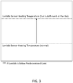
- FIG. 3 illustrates the Lambda sensor heating profile utilized responsive to a fuel cutoff event or the like in accordance with the present disclosure.
- FIG. 4 is a block diagram of the ECU 14 of FIG. 1 .
- the ECU 14 and the components thereof are configured to implement the exhaust emissions method of the present disclosure. While an ECU 14 is described, other controllers with similar hardware/software configurations are also contemplated.
- the processor 102 is a hardware device for executing software instructions embodied in a non-transitory computer-readable medium.
- the processor 102 may be any custom made or commercially available processor, a central processing unit (CPU), an auxiliary processor among several processors associated with a server, a semiconductor-based microprocessor (in the form of a microchip or chipset), or generally any device for executing software instructions.
- the processor 102 is configured to execute software stored within the memory 110, to communicate data to and from the memory 110, and to generally control operations of the ECU 12 pursuant to the software instructions.
- I/O interfaces 104 may be used to receive user input from and/or for providing system output to one or more devices or components.
- a network interface 106 may be used to enable the ECU 12 to communicate on a network, such as the Internet or a Local Area Network (LAN).
- a network such as the Internet or a Local Area Network (LAN).
- the network interface 106 may include, for example, an Ethernet card or adapter (e.g., 10BaseT, Fast Ethernet, Gigabit Ethernet, or 10GbE) or a Wireless Local Area Network (WLAN) card or adapter (e.g., 802.11a/b/g/n/ac).
- the network interface 106 may include address, control, and/or data connections to enable appropriate communications on the network.
- a data store 108 may be used to store data.
- the data store 108 may include any of volatile memory elements (e.g., random access memory (RAM, such as DRAM, SRAM, SDRAM, and the like)), nonvolatile memory elements (e.g., ROM, hard drive, tape, CDROM, and the like), and combinations thereof.
- the data store 108 may incorporate electronic, magnetic, optical, and/or other types of storage media.
- the data store 108 may be located internal to the ECU 12, such as, for example, an internal hard drive connected to the local interface 112 in the ECU 12.
- the data store 108 may be located external to the control system 100 such as, for example, an external hard drive connected to the I/O interfaces 104 (e.g., a SCSI or USB connection).
- the data store 108 may be connected to the ECU 12 through a network, such as, for example, a network-attached file server.
- the memory 110 may include any of volatile memory elements (e.g., random access memory (RAM, such as DRAM, SRAM, SDRAM, etc.)), nonvolatile memory elements (e.g., ROM, hard drive, tape, CDROM, etc.), and combinations thereof.
- RAM random access memory
- nonvolatile memory elements e.g., ROM, hard drive, tape, CDROM, etc.
- the memory 110 may incorporate electronic, magnetic, optical, and/or other types of storage media. Note that the memory 110 may have a distributed architecture, where various components are situated remotely from one another but can be accessed by the processor 102.
- the software in memory 110 may include one or more software programs, each of which includes an ordered listing of executable instructions for implementing logical functions.
- the software in the memory 110 includes a suitable operating system (O/S) 114 and one or more programs 116.
- the operating system 114 essentially controls the execution of other computer programs, such as the one or more programs 116, and provides scheduling, input-output control, file and data management, memory management, and communication control and related services.
- the one or more programs 116 may be configured to implement the various processes, algorithms, methods, techniques, etc. described herein.
- Computer-readable media may include computer-readable storage media, which corresponds to a tangible medium such as data storage media, or communication media including any medium that facilitates transfer of a computer program from one place to another, e.g., according to a communication protocol.
- computer-readable media generally may correspond to (1) a tangible computer-readable storage medium that is non-transitory or (2) a communication medium, such as a signal or carrier wave.
- Data storage media may be any available media that can be accessed by one or more computers or one or more processors to retrieve instructions, code and/or data structures for implementation of the techniques described in this disclosure.
- a computer program product may include a computer-readable medium.
- such computer-readable storage media can include random-access memory (RAM), read-only memory (ROM), electrically erasable-programmable read-only memory (EEPROM), compact disc read-only memory (CDROM) or other optical disc storage, magnetic disk storage, or other magnetic storage devices, flash memory, or any other medium that can be used to store desired program code in the form of instructions or data structures and that can be accessed by a computer. Also, any connection is properly termed a computer-readable medium.
- RAM random-access memory
- ROM read-only memory
- EEPROM electrically erasable-programmable read-only memory
- CDROM compact disc read-only memory
- flash memory or any other medium that can be used to store desired program code in the form of instructions or data structures and that can be accessed by a computer.
- any connection is properly termed a computer-readable medium.
- IR infrared
- RF radio frequency
- microwave the coaxial cable, fiber optic cable, twisted pair, DSL, or wireless technologies, such as IR, RF, and microwave are included in the definition of medium.
- computer-readable storage media and data storage media do not include connections, carrier waves, signals, or other transitory media, but are instead directed to non-transitory, tangible storage media.
- Disk and disc includes compact disc (CD), laser disc, optical disc, digital versatile disc (DVD), and Blu-ray disc, where disks usually reproduce data magnetically, while discs reproduce data optically with lasers. Combinations of the above should also be included within the scope of computer-readable media.
- processors such as one or more digital signal processors (DSPs), general purpose microprocessors, application specific integrated circuits (ASICs), field programmable gate arrays (FPGAs), complex programmable logic devices (CPLDs), or other equivalent integrated or discrete logic circuitry.
- DSPs digital signal processors
- ASICs application specific integrated circuits
- FPGAs field programmable gate arrays
- CPLDs complex programmable logic devices
- processors such as one or more digital signal processors (DSPs), general purpose microprocessors, application specific integrated circuits (ASICs), field programmable gate arrays (FPGAs), complex programmable logic devices (CPLDs), or other equivalent integrated or discrete logic circuitry.
- DSPs digital signal processors
- ASICs application specific integrated circuits
- FPGAs field programmable gate arrays
- CPLDs complex programmable logic devices
- the techniques of this disclosure may be implemented in a wide variety of devices or apparatuses, including an integrated circuit (IC) or a set of ICs (e.g., a chip set).
- IC integrated circuit
- a set of ICs e.g., a chip set.
- Various components, modules, or units are described in this disclosure to emphasize functional aspects of devices configured to perform the disclosed techniques, but do not necessarily require realization by different hardware units. Rather, as described above, various units may be combined in a hardware unit or provided by a collection of interoperative hardware units, including one or more processors as described above, in conjunction with suitable software and/or firmware.
Landscapes
- Engineering & Computer Science (AREA)
- Chemical & Material Sciences (AREA)
- Combustion & Propulsion (AREA)
- Mechanical Engineering (AREA)
- General Engineering & Computer Science (AREA)
- Chemical Kinetics & Catalysis (AREA)
- Health & Medical Sciences (AREA)
- Toxicology (AREA)
- Combined Controls Of Internal Combustion Engines (AREA)
- Electrical Control Of Air Or Fuel Supplied To Internal-Combustion Engine (AREA)
Abstract
Description
- The present disclosure relates generally to the automotive field. More particularly, the present disclosure relates to a method and system for recovering vehicle Lambda sensors with an external air supply.
- Most vehicles powered by an internal combustion engine (ICE) utilize one or more Lambda (O2) sensors in their exhaust emissions systems. In general, a Lambda sensor works together with a vehicle's fuel injection system, catalytic converter, and engine management system (EMS) or electronic control unit (ECU) to help achieve the lowest possible output of environmentally harmful engine emissions. The Lambda sensor monitors the percentage of unburned O2 present in the vehicle's exhaust gases. The Lambda sensor, responsive to the detection of a lean mixture with too high an O2 content or a rich mixture with too low an O2 content, transmits an appropriate voltage signal to the ECU, which then adjusts the air/fuel ratio entering the catalytic converter. The goal is to keep the air/fuel ratio very close to a "stoichiometric" point, which is the calculated ideal air/fuel ratio entering the catalytic converter. Lambda sensors can be utilized at multiple points before and after the catalytic converter. Theoretically, at the "stoichiometric" point, all of the fuel will be burned using almost all of the O2 in the air, and the remaining O2 will be exactly the right quantity for the catalytic converter to function efficiently.
- A typical Lambda sensor includes a hollow zirconium dioxide sensor element. The inner side of the sensor element is in contact with the ambient air, while the outer side is in the exhaust gas flow. Both sides are coated with a thin porous platinum layer that acts as an electrode. When the zirconium dioxide sensor element reaches its operating temperature, O2 ions start to flow based on the concentration gradient. O2 ions move from the reference side in the direction of the exhaust gas to balance this out. This creates a voltage potential difference and a voltage is applied to the connected platinum electrodes. In contrast, titanium dioxide sensors do not produce any voltage. Rather, their resistance changes commensurate with the residual O2 concentration in the exhaust gas. Thus, reference air is not required.
- An important part of any engine control software in the ECU is the exhaust emissions system controlling engine operation to meet legislated emissions requirements. An important function of this exhaust emissions system is to enrich the catalyst after a fuel cutoff event or the like, when the catalyst is saturated with O2. If the timing of this catalyst enrichment is slightly off, then emissions will rapidly increase. Catalyst enrichment is realized by lowering the target Lambda to a rich air/fuel mixture (typically about 0.8), where the lambda is an air-fuel equivalence ratio that is the ratio of the actual air-fuel ratio to the air-fuel ratio at the stoichiometric point. Thus, the Lambda is controlled by the Lambda controller during the catalyst enrichment phase to ensure correct timing of the catalyst enrichment.
- Disadvantageously, many Lambda sensors become downwards limited and cannot read rich air/fuel ratios below about 0.95 after a fuel cutoff event or the like. This is a hardware problem that has not been rectified and results in wrong calculations and unacceptable tailpipe emissions exceeding legislative requirements after a fuel cutoff event or the like. This issue is dealt with by the present disclosure.
- In general, the present disclosure carefully controls the heating duty cycle of a Lambda sensor, utilizing higher heating temperatures during lean phases, such as a fuel cutoff event or the like. Essentially, there is a calibration routine that is executed via software and allows a Lambda sensor to preserve full function over time and to recover from an erroneous state. In particular, controlling the heating duty cycle for the Lambda sensor by increasing the heating temperature during lean phases allows the Lambda sensor to recover from an erroneous state where rich Lambda measurement is limited and in some instances, preservers full function of the Lambda sensor over time by preventing the Lambda sensor from falling into the erroneous state.
- In some embodiments, Lambda sensor recovery is obtained by increasing a heating temperature of the heater element. This Lambda sensor recovery is applied at lean fuel events, such as fuel cutoff events, in-vehicle after run or "start/stop" engine shut off events, and the like. This recovery can be used without affecting operation of the Lambda sensor during general operation of the vehicle and can be controlled to maintain operation thereof below a destructive limit. This recovery can also be used without effecting alteration of sensor Lambda value readings that would lead to higher tailpipe emissions. If this method is applied from new, the probability of the Lambda sensor keeping its life expectancy will increase.
- As is conventional, the heated Lambda sensor has an internal heater circuit that brings the Lambda sensor up to operating temperature more quickly than an unheated Lambda sensor, for example, within 20 to 60 seconds, depending on the Lambda sensor, and keeps the Lambda sensor hot even when the engine is idling for a long period of time. The faster the Lambda sensor heats up, the quicker the system can enter closed loop fuel control, optimizing catalytic converter efficiency.
- In accordance with the present disclosure, higher heating element temperatures are utilized during lean phases, such as a fuel cutoff event or the like. Further, an applied voltage of the Lambda sensor can also be increased to increase the heating temperature for the Lambda sensor. This can be performed separate or in conjunction with an increase in temperature of the heating element. Further, the heating temperature of the Lambda sensor may be a function of a heating duty cycle increase amount during a Lambda shift to a rich fuel to air ratio.
- In one illustrative embodiment, the present disclosure provides a vehicle exhaust emissions control method implemented responsive to a fuel cutoff event or the like. The method includes detecting a fuel limiting event resulting in a reduced air/fuel ratio in an exhaust emissions system of a vehicle, the reduced air/fuel ratio potentially faulting a Lambda sensor disposed in the exhaust emissions system. The method also includes selectively increasing a heating temperature for the Lambda sensor responsive to the reduced air/fuel ratio, thereby performing one of preserving full function of the Lambda sensor during the fuel limiting event and recovering a faulting of the Lambda sensor during the fuel limiting event.
- In one embodiment, the heating temperature for the Lambda sensor is increased using a heating element coupled to an electronic control unit of the vehicle. Optionally, the heating temperature for the Lambda sensor is also increased by increasing an applied voltage to the Lambda sensor.
- In some embodiments, the electronic control unit is further adapted to control operation of an engine of the vehicle. The electronic control unit is further adapted to control operation of a catalytic converter of the vehicle. The Lambda sensor is disposed at one of upstream of the catalytic converter and downstream of the catalytic converter.
- In another embodiment, the heating temperature for the Lambda sensor is at least partially increased by increasing an applied voltage to the Lambda sensor.
- In a further embodiment, the heating temperature for the Lambda sensor is a function of a heating duty cycle increase amount during a Lambda shift to a rich fuel to air ratio.
- In another illustrative embodiment, the present disclosure provides a non-transitory computer-readable medium stored in a memory and executed by a processor to control vehicle exhaust emissions responsive to a fuel cutoff event or the like, performing the steps comprising: detecting a fuel limiting event resulting in a reduced air/fuel ratio in an exhaust emissions system of a vehicle, the reduced air/fuel ratio potentially faulting a Lambda sensor disposed in the exhaust emissions system; and selectively increasing a heating temperature for the Lambda sensor responsive to the reduced air/fuel ratio, thereby performing one of preserving full function of the Lambda sensor during the fuel limiting event and recovering a faulting of the Lambda sensor during the fuel limiting event.
- In one embodiment, the heating temperature for the Lambda sensor is increased using a heating element coupled to an electronic control unit of the vehicle.
- In some embodiments, the electronic control unit is further adapted to control operation of an engine of the vehicle. The electronic control unit is further adapted to control operation of a catalytic converter of the vehicle. The Lambda sensor is disposed at one of upstream of the catalytic converter and downstream of the catalytic converter.
- In another embodiment, the heating temperature for the Lambda sensor is at least partially increased by increasing an applied voltage to the Lambda sensor.
- In a further embodiment, the heating temperature for the Lambda sensor is a function of a heating duty cycle increase amount during a Lambda shift to a rich fuel to air ratio.
- In a further illustrative embodiment, the present disclosure provides a vehicle exhaust emissions control system actuated responsive to a fuel cutoff event or the like. The exhaust emissions control system includes a lambda sensor and an electronic control unit. The Lambda sensor is disposed in an exhaust emissions system. The electronic control unit is adapted to (1) detect a fuel limiting event resulting in a reduced air/fuel ratio in the exhaust emissions system of a vehicle, the reduced air/fuel ratio potentially faulting the Lambda sensor and (2) selectively increasing a heating temperature for the Lambda sensor responsive to the reduced air/fuel ratio, thereby performing one of preserving full function of the Lambda sensor during the fuel limiting event and recovering a faulting of the Lambda sensor during the fuel limiting event.
- In one embodiment, the vehicle exhaust emissions control system further includes a heating element coupled to the electronic control unit adapted to increase the heating temperature for the Lambda sensor in response to an instruction received from the electronic control unit that is provided responsive to the reduced air/fuel ratio. Optionally, the heating temperature for the Lambda sensor is also increased by increasing an applied voltage to the Lambda sensor.
- In some embodiments, the electronic control unit is further adapted to control operation of an engine of the vehicle. The electronic control unit is further adapted to control operation of a catalytic converter of the vehicle. The Lambda sensor is disposed upstream of the catalytic converter. Alternatively, the Lambda sensor is disposed downstream of the catalytic converter.
- In another embodiment, the heating temperature for the Lambda sensor is at least partially increased by increasing an applied voltage to the Lambda sensor.
- In a further embodiment, the heating temperature for the Lambda sensor is a function of a heating duty cycle increase amount during a Lambda shift to a rich fuel to air ratio.
- The present disclosure is illustrated and described herein with reference to the various drawings, in which like reference numbers are used to denote like method steps/system components, as appropriate, and in which:
-
FIG. 1 is a schematic diagram illustrating one illustrative embodiment of the exhaust emissions system of the present disclosure, implementing a novel Lambda sensor heating routine in the event of s fuel cutoff event or the like; -
FIG. 2 is a flowchart illustrating one illustrative embodiment of the exhaust emissions method of the present disclosure, implementing a novel Lambda sensor heating routine in the event of s fuel cutoff event or the like; -
FIG. 3 is plot illustrating one illustrative embodiment of the exhaust emissions scheme of the present disclosure, implementing a novel Lambda sensor heating routine in the event of s fuel cutoff event or the like; and -
FIG. 4 is a block diagram of the Electronic Control Unit (ECU) ofFIG. 1 . - Again, the present disclosure carefully controls the heating duty cycle of a Lambda sensor, utilizing higher heating temperatures during lean phases, such as a fuel cutoff event or the like to recover the Lambda sensor from an erroneous event and to ensure that the Lambda sensor operates within a proper operating temperature range during lean phases, such as lean fuel events. Essentially, there is a calibration routine that is executed via software and allows a Lambda sensor to recover from an erroneous state. By controlling the heating duty cycle for the Lambda sensor heating the Lambda sensor at higher temperatures allows the Lambda sensor to recover from an erroneous state where rich Lambda measurement is limited. Lambda sensor recovery can be obtained by increasing heater element temperatures at lean fuel events, such as fuel cutoff events, in-vehicle after run, "start/stop" engine shut off events, and the like. This heating operation for Lambda sensor recovery at lean fuel events can be used without effecting normal operation of the Lambda sensor (during general operation/non-lean fuel events). This recovery can be used without affecting operation of the Lambda sensor during general operation of the vehicle and can be controlled to maintain operation thereof below a destructive limit. This recovery can also be used without effecting alteration of sensor Lambda value readings that would lead to higher tailpipe emissions. Further, if this method is applied when a new Lambda sensor is installed, the probability of the Lambda sensor keeping its life expectancy will increase.
- As is conventional, the heated Lambda sensor has an internal heater circuit that brings the Lambda sensor up to a general operating temperature more quickly than an unheated Lambda sensor, for example, within 20 to 60 seconds, depending on the Lambda sensor, and keeps the Lambda sensor hot (at the general operating temperature) even when the engine is idling for a long period of time. The faster the Lambda sensor heats up, the quicker the system can enter closed loop fuel control, optimizing catalytic converter efficiency. In accordance with the present disclosure, higher heating temperatures are utilized during lean phases, such as a fuel cutoff event or the like. In particular, the heating temperature is set at a higher heating temperature during a lean fuel event than the general heating temperature maintained during general operation of the Lambda sensor during non-lean fuel events, such as during general operation of the vehicle.
- To aid in the recovery of the Lambda sensor during a lean fuel event, in some embodiments, the applied voltage to the Lambda sensor is increased. In embodiments, the applied voltage provides at least a portion of the heating temperature increase during the recovery of the Lambda sensor. Thus, advantageously, full recovery of the Lambda sensor can be obtained faster/easier with an increased applied voltage to the Lambda sensor in combination with an increase in the heating temperature applied by a heating element.
- Full recovery of the Lambda sensor is also aided by operation of the vehicle at a lean Lambda prior to and during a lean fuel event. Thus, in some embodiments, the vehicle is transitioned to a lean Lambda operation in response to a predicted lean fuel event and prior to the occurrence of the lean fuel event.
- Further, to ensure that the Lambda sensor is not damaged and to maintain a life expectancy of the Lambda sensor, in some embodiments, the heating of the Lambda sensor during a lean fuel event is increased above the general operating temperatures of the heating element to recover the Lambda sensor, while being kept below a predetermined temperature that would significantly reduce the life cycle of the Lambda sensor, such as destructive heating temperatures for the Lambda sensor and temperatures that would cause the Lambda sensor to increase too much. Similarly, the heating duty of a heating element, while increased during a lean fuel event, is also maintained below a predetermined temperature that would significantly reduce a life cycle of the heating element.
- Referring now specifically to
FIG. 1 , in one illustrative embodiment, theexhaust emissions system 10 of the present disclosure includes theECU 12 which is electrically coupled to theLambda sensor 14 and aheating element 16. TheECU 12 is operable for executing a Lambda sensor heating cycle algorithm 18 in the event of a fuel cutoff event or the like, when it is expected that the air/fuel ratio will suddenly spike upwards. In such cases, theheating element 16 is actuated to increase a heating temperature for theLambda sensor 14. This increase in heating temperature fully recovers a failed Lambda sensor, and in many instances, preserves full function of the Lambda sensor over time. Thus, the heating temperature for theLambda sensor 14 is hotter than usual when the fuel is restored and the air/fuel ratio suddenly changes during a lean fuel event, for example. As described previously, under such circumstances, theLambda sensor 14 normally fails to function properly, but this fault is now prevented by the novel heating routine. As is illustrated, theECU 12 is also electrically coupled to theengine 20 of the vehicle, as well as thecatalytic converter 22. - Referring now specifically to
FIG. 2 , in another illustrative embodiment, theexhaust emissions method 30 of the present disclosure includes, upon detecting a fuel cutoff event or the like 32, in which it is expected that the air/fuel ratio will suddenly spike upwards, the ECU 12 (FIG. 1 ) executes a Lambda sensor heating cycle algorithm 18 (FIG. 1 ) whereby a heating temperature of the Lambda sensor 14 (FIG. 1 ) is increased 34. The increase in the heating temperature of the Lambda sensor 14 (FIG. 1 ) results in a heating temperature that is higher while the air-fuel ratio is expected to spike than the heating temperature during general operation of the Lambda sensor, such as during non-lean fuel events and general operation of the vehicle. Thus, theLambda sensor 14 is heated by a higher than usual heating temperature to preserves full function of the Lambda sensor over time and to recover a failed Lambda sensor. Under such circumstances, theLambda sensor 14 normally fails to function properly, but this fault is now prevented by the novel heating routine. - In embodiments, the heating temperature of the Lambda sensor 14 (
FIG. 1 ) is increased by increasing a heating duty cycle of the heating element 16 (FIG. 1 ), which is actuated to increase the heating temperature supplied to the Lambda sensor 14 (FIG. 1 ). - In embodiments, the heating temperature of the Lambda sensor 14 (
FIG. 1 ) is at least partially increased by increasing a voltage applied to the Lambda sensor 14 (FIG. 1 ). In these embodiments, and in particular where both the heating duty cycle of the heating element 16 (FIG. 1 ) and the applied voltage to the Lambda sensor 14 (FIG. 1 ) is increased, preservation of full function of the Lambda sensor can be easier to maintain and full recovery of a failed Lambda sensor can be obtained faster. - In embodiments, the heating temperature of the Lambda sensor 14 (
FIG. 1 ) during a fuel limiting event is a function of a heating duty cycle increase amount during a Lambda shift to a rich fuel to air ratio. - In embodiments, the heating temperature of the Lambda sensor 14 (
FIG. 1 ) is further maintained below a predetermined temperature. The predetermined temperature is at least one of a temperature that would significantly reduce the life cycle of the Lambda sensor, such as destructive heating temperatures for the Lambda sensor and temperatures that would cause the Lambda sensor to increase too much and temperature that would significantly reduce a life cycle of the heating element. In some embodiments, the predetermined temperature is selected based on the type and materials of the Lambda sensor and/or the heating element. -
FIG. 3 illustrates the Lambda sensor heating profile utilized responsive to a fuel cutoff event or the like in accordance with the present disclosure. -
FIG. 4 is a block diagram of theECU 14 ofFIG. 1 . In embodiments, theECU 14 and the components thereof are configured to implement the exhaust emissions method of the present disclosure. While anECU 14 is described, other controllers with similar hardware/software configurations are also contemplated. In the embodiment illustrated, theprocessor 102 is a hardware device for executing software instructions embodied in a non-transitory computer-readable medium. - The
processor 102 may be any custom made or commercially available processor, a central processing unit (CPU), an auxiliary processor among several processors associated with a server, a semiconductor-based microprocessor (in the form of a microchip or chipset), or generally any device for executing software instructions. When theECU 12 is in operation, theprocessor 102 is configured to execute software stored within thememory 110, to communicate data to and from thememory 110, and to generally control operations of theECU 12 pursuant to the software instructions. - I/O interfaces 104 may be used to receive user input from and/or for providing system output to one or more devices or components. A
network interface 106 may be used to enable theECU 12 to communicate on a network, such as the Internet or a Local Area Network (LAN). - The
network interface 106 may include, for example, an Ethernet card or adapter (e.g., 10BaseT, Fast Ethernet, Gigabit Ethernet, or 10GbE) or a Wireless Local Area Network (WLAN) card or adapter (e.g., 802.11a/b/g/n/ac). Thenetwork interface 106 may include address, control, and/or data connections to enable appropriate communications on the network. - A
data store 108 may be used to store data. Thedata store 108 may include any of volatile memory elements (e.g., random access memory (RAM, such as DRAM, SRAM, SDRAM, and the like)), nonvolatile memory elements (e.g., ROM, hard drive, tape, CDROM, and the like), and combinations thereof. Moreover, thedata store 108 may incorporate electronic, magnetic, optical, and/or other types of storage media. In one example, thedata store 108 may be located internal to theECU 12, such as, for example, an internal hard drive connected to thelocal interface 112 in theECU 12. Additionally, in another embodiment, thedata store 108 may be located external to the control system 100 such as, for example, an external hard drive connected to the I/O interfaces 104 (e.g., a SCSI or USB connection). - In a further embodiment, the
data store 108 may be connected to theECU 12 through a network, such as, for example, a network-attached file server. Thememory 110 may include any of volatile memory elements (e.g., random access memory (RAM, such as DRAM, SRAM, SDRAM, etc.)), nonvolatile memory elements (e.g., ROM, hard drive, tape, CDROM, etc.), and combinations thereof. Moreover, thememory 110 may incorporate electronic, magnetic, optical, and/or other types of storage media. Note that thememory 110 may have a distributed architecture, where various components are situated remotely from one another but can be accessed by theprocessor 102. The software inmemory 110 may include one or more software programs, each of which includes an ordered listing of executable instructions for implementing logical functions. The software in thememory 110 includes a suitable operating system (O/S) 114 and one ormore programs 116. Theoperating system 114 essentially controls the execution of other computer programs, such as the one ormore programs 116, and provides scheduling, input-output control, file and data management, memory management, and communication control and related services. The one ormore programs 116 may be configured to implement the various processes, algorithms, methods, techniques, etc. described herein. - In one or more examples, the functions described may be implemented in hardware, software, firmware, or any combination thereof. If implemented in software, the functions may be stored on or transmitted over as one or more instructions or code on a computer-readable medium and executed by a hardware-based processing unit, such as
ECU 12. Computer-readable media may include computer-readable storage media, which corresponds to a tangible medium such as data storage media, or communication media including any medium that facilitates transfer of a computer program from one place to another, e.g., according to a communication protocol. In this manner, computer-readable media generally may correspond to (1) a tangible computer-readable storage medium that is non-transitory or (2) a communication medium, such as a signal or carrier wave. Data storage media may be any available media that can be accessed by one or more computers or one or more processors to retrieve instructions, code and/or data structures for implementation of the techniques described in this disclosure. A computer program product may include a computer-readable medium. - By way of example, and not limitation, such computer-readable storage media can include random-access memory (RAM), read-only memory (ROM), electrically erasable-programmable read-only memory (EEPROM), compact disc read-only memory (CDROM) or other optical disc storage, magnetic disk storage, or other magnetic storage devices, flash memory, or any other medium that can be used to store desired program code in the form of instructions or data structures and that can be accessed by a computer. Also, any connection is properly termed a computer-readable medium. For example, if instructions are transmitted from a website, server, or other remote source using a coaxial cable, fiber optic cable, twisted pair, digital subscriber line (DSL), or wireless technologies such as infrared (IR), radio frequency (RF), and microwave, then the coaxial cable, fiber optic cable, twisted pair, DSL, or wireless technologies, such as IR, RF, and microwave are included in the definition of medium. It should be understood, however, that computer-readable storage media and data storage media do not include connections, carrier waves, signals, or other transitory media, but are instead directed to non-transitory, tangible storage media. Disk and disc, as used herein, includes compact disc (CD), laser disc, optical disc, digital versatile disc (DVD), and Blu-ray disc, where disks usually reproduce data magnetically, while discs reproduce data optically with lasers. Combinations of the above should also be included within the scope of computer-readable media.
- Instructions may be executed by one or more processors, such as one or more digital signal processors (DSPs), general purpose microprocessors, application specific integrated circuits (ASICs), field programmable gate arrays (FPGAs), complex programmable logic devices (CPLDs), or other equivalent integrated or discrete logic circuitry. Accordingly, the term "processor," as used herein may refer to any of the foregoing structure or any other structure suitable for implementation of the techniques described herein. In addition, in some aspects, the functionality described herein may be provided within dedicated hardware and/or software modules. Also, the techniques could be fully implemented in one or more circuits or logic elements.
- The techniques of this disclosure may be implemented in a wide variety of devices or apparatuses, including an integrated circuit (IC) or a set of ICs (e.g., a chip set). Various components, modules, or units are described in this disclosure to emphasize functional aspects of devices configured to perform the disclosed techniques, but do not necessarily require realization by different hardware units. Rather, as described above, various units may be combined in a hardware unit or provided by a collection of interoperative hardware units, including one or more processors as described above, in conjunction with suitable software and/or firmware.
- Although the present disclosure is illustrated and described herein with reference to preferred embodiments and specific examples thereof, it will be readily apparent to persons of ordinary skill in the art that other embodiments and examples may perform similar functions and/or achieve like results. All such equivalent embodiments and examples are within the spirit and scope of the present invention, are contemplated thereby, and are intended to be covered by the following non-limiting claims for all purposes.
Claims (15)
- A vehicle exhaust emissions control method, comprising:detecting (32) a fuel limiting event resulting in a reduced air/fuel ratio in an exhaust emissions system (10) of a vehicle, the reduced air/fuel ratio potentially faulting a Lambda sensor (14) disposed in the exhaust emissions system; andselectively increasing a heating temperature (34) for the Lambda sensor responsive to the reduced air/fuel ratio, thereby performing one of preserving full function of the Lambda sensor during the fuel limiting event and recovering a faulting of the Lambda sensor during the fuel limiting event.
- The method of claim 1, wherein the heating temperature for the Lambda sensor is increased using a heating element (16) coupled to an electronic control unit of the vehicle.
- The method of claim 2, wherein the heating temperature for the Lambda sensor is also increased by increasing an applied voltage to the Lambda sensor.
- The method of claim 2, wherein the electronic control unit is further adapted to control operation of an engine of the vehicle.
- The method of claim 2, wherein the electronic control unit is further adapted to control operation of a catalytic converter of the vehicle.
- The method of claim 5, wherein the Lambda sensor is disposed at one of upstream of the catalytic converter and downstream of the catalytic converter.
- The method of claim 1, wherein the heating temperature for the Lambda sensor is at least partially increased by increasing an applied voltage to the Lambda sensor.
- The method of claim 1, wherein the heating temperature for the Lambda sensor is a function of a heating duty cycle increase amount during a Lambda shift to a rich fuel to air ratio.
- A vehicle exhaust emissions control system (10), comprising:a lambda sensor (14) disposed in an exhaust emissions system; andan electronic control unit (12) adapted to, 1) detect a fuel limiting event resulting in a reduced air/fuel ratio in the exhaust emissions system of a vehicle, the reduced air/fuel ratio potentially faulting the Lambda sensor and, 2) selectively increase a heating temperature for the Lambda sensor responsive to the reduced air/fuel ratio, thereby performing one of preserving full function of the Lambda sensor during the fuel limiting event and recovering a faulting of the Lambda sensor during the fuel limiting event.
- The system of claim 9, further comprising:
a heating element (16) coupled to the electronic control unit adapted to increase the heating temperature for the Lambda sensor in response to an instruction received from the electronic control unit that is provided responsive to the reduced air/fuel ratio. - The system of claim 10, wherein the heating temperature for the Lambda sensor is also increased by increasing an applied voltage to the Lambda sensor.
- The system of claim 10, wherein the electronic control unit is further adapted to control operation of an engine of the vehicle.
- The system of claim 10, wherein the electronic control unit is further adapted to control operation of a catalytic converter of the vehicle, and wherein the Lambda sensor is disposed at one of upstream of the catalytic converter and downstream of the catalytic converter.
- The system of claim 9, wherein the heating temperature for the Lambda sensor is at least partially increased by increasing an applied voltage to the Lambda sensor.
- The system of claim 9, wherein the heating temperature for the Lambda sensor is a function of a heating duty cycle increase amount during a Lambda shift to a rich fuel to air ratio.
Applications Claiming Priority (2)
| Application Number | Priority Date | Filing Date | Title |
|---|---|---|---|
| US201962952709P | 2019-12-23 | 2019-12-23 | |
| US17/122,387 US20210189984A1 (en) | 2019-12-23 | 2020-12-15 | Method and system for recovering vehicle lambda sensors with an external air supply |
Publications (1)
| Publication Number | Publication Date |
|---|---|
| EP3842628A1 true EP3842628A1 (en) | 2021-06-30 |
Family
ID=73855231
Family Applications (1)
| Application Number | Title | Priority Date | Filing Date |
|---|---|---|---|
| EP20214825.0A Pending EP3842628A1 (en) | 2019-12-23 | 2020-12-17 | Method and system for recovering vehicle lambda sensors |
Country Status (2)
| Country | Link |
|---|---|
| US (1) | US20210189984A1 (en) |
| EP (1) | EP3842628A1 (en) |
Citations (4)
| Publication number | Priority date | Publication date | Assignee | Title |
|---|---|---|---|---|
| US20110220084A1 (en) * | 2010-03-04 | 2011-09-15 | Robert Bosch Gmbh | Method for operating an internal combustion engine |
| US20140346041A1 (en) * | 2012-02-14 | 2014-11-27 | Toyota Jidosha Kabushiki Kaisha | Control device for exhaust gas sensor |
| US20170016376A1 (en) * | 2015-07-13 | 2017-01-19 | Hyundai Motor Company | Apparatus and method for removing poison of lamda sensor |
| US20170298853A1 (en) * | 2014-09-26 | 2017-10-19 | Toyota Jidosha Kabushiki Kaisha | Control device and control method of internal combustion engine |
Family Cites Families (3)
| Publication number | Priority date | Publication date | Assignee | Title |
|---|---|---|---|---|
| JP3438531B2 (en) * | 1997-05-30 | 2003-08-18 | 三菱自動車工業株式会社 | Heater control device for oxygen sensor |
| JP5136226B2 (en) * | 2008-06-04 | 2013-02-06 | 日産自動車株式会社 | Engine air-fuel ratio sensor shift fault diagnosis device |
| US8055438B2 (en) * | 2009-02-20 | 2011-11-08 | Honda Motor Co., Ltd. | Air-fuel ratio sensor early activation feedback system and method |
-
2020
- 2020-12-15 US US17/122,387 patent/US20210189984A1/en not_active Abandoned
- 2020-12-17 EP EP20214825.0A patent/EP3842628A1/en active Pending
Patent Citations (4)
| Publication number | Priority date | Publication date | Assignee | Title |
|---|---|---|---|---|
| US20110220084A1 (en) * | 2010-03-04 | 2011-09-15 | Robert Bosch Gmbh | Method for operating an internal combustion engine |
| US20140346041A1 (en) * | 2012-02-14 | 2014-11-27 | Toyota Jidosha Kabushiki Kaisha | Control device for exhaust gas sensor |
| US20170298853A1 (en) * | 2014-09-26 | 2017-10-19 | Toyota Jidosha Kabushiki Kaisha | Control device and control method of internal combustion engine |
| US20170016376A1 (en) * | 2015-07-13 | 2017-01-19 | Hyundai Motor Company | Apparatus and method for removing poison of lamda sensor |
Also Published As
| Publication number | Publication date |
|---|---|
| US20210189984A1 (en) | 2021-06-24 |
Similar Documents
| Publication | Publication Date | Title |
|---|---|---|
| CN111502850B (en) | Control device for internal combustion engine | |
| JP6550689B2 (en) | Exhaust gas sensor heater control device | |
| US20090139212A1 (en) | DIAGNOSTIC DEVICE FOR NOx SENSOR | |
| JP2006161625A (en) | Exhaust temperature estimation device for internal combustion engine | |
| CN110107415B (en) | Engine cold start method, electronic control unit and system | |
| JP6241360B2 (en) | Exhaust gas sensor heater control device | |
| CN111164280B (en) | Method for operating a catalyst system of an internal combustion engine and catalyst system | |
| US6859719B2 (en) | Control system and control method for controlling heater, and engine control unit | |
| US20210189984A1 (en) | Method and system for recovering vehicle lambda sensors with an external air supply | |
| JPH03100353A (en) | How to determine activation of exhaust gas concentration sensor with heater | |
| JP4595718B2 (en) | Abnormality detection device for air-fuel ratio sensor and internal combustion engine equipped with the abnormality detection device | |
| JP2005121005A (en) | Oxygen sensor heating control method for vehicle engine | |
| EP1591635B1 (en) | Regeneration control of diesel particulate filter | |
| JP2000112837A (en) | Memory check device and check method | |
| KR20210143489A (en) | Method for activating a lambda sensor, apparatus and post-treatment system providing the same | |
| WO2002018935A1 (en) | High driveability index fuel detection by exhaust gas temperature measurement | |
| US9222852B2 (en) | Method for detecting the operational readiness of a jump lambda sensor | |
| JP4706928B2 (en) | Exhaust gas sensor heater control device | |
| JP2007120390A (en) | Exhaust gas sensor heater control device | |
| JP2006194826A (en) | Oxygen sensor deterioration judgment device | |
| JP2010145256A (en) | Heater control device of emission gas sensor | |
| JP2005002974A (en) | Exhaust gas sensor heater control device | |
| JP7758877B2 (en) | How to Identify a Load Disconnect Error | |
| JP2516086B2 (en) | Intake air flow rate measuring device for internal combustion engine | |
| JP2006083797A (en) | Ignition control device for internal combustion engine |
Legal Events
| Date | Code | Title | Description |
|---|---|---|---|
| PUAI | Public reference made under article 153(3) epc to a published international application that has entered the european phase |
Free format text: ORIGINAL CODE: 0009012 |
|
| STAA | Information on the status of an ep patent application or granted ep patent |
Free format text: STATUS: THE APPLICATION HAS BEEN PUBLISHED |
|
| AK | Designated contracting states |
Kind code of ref document: A1 Designated state(s): AL AT BE BG CH CY CZ DE DK EE ES FI FR GB GR HR HU IE IS IT LI LT LU LV MC MK MT NL NO PL PT RO RS SE SI SK SM TR |
|
| STAA | Information on the status of an ep patent application or granted ep patent |
Free format text: STATUS: REQUEST FOR EXAMINATION WAS MADE |
|
| 17P | Request for examination filed |
Effective date: 20220103 |
|
| RBV | Designated contracting states (corrected) |
Designated state(s): AL AT BE BG CH CY CZ DE DK EE ES FI FR GB GR HR HU IE IS IT LI LT LU LV MC MK MT NL NO PL PT RO RS SE SI SK SM TR |
|
| STAA | Information on the status of an ep patent application or granted ep patent |
Free format text: STATUS: EXAMINATION IS IN PROGRESS |
|
| P01 | Opt-out of the competence of the unified patent court (upc) registered |
Effective date: 20230828 |
|
| 17Q | First examination report despatched |
Effective date: 20230913 |