EP3842369A1 - Denesting apparatus - Google Patents
Denesting apparatus Download PDFInfo
- Publication number
- EP3842369A1 EP3842369A1 EP19219765.5A EP19219765A EP3842369A1 EP 3842369 A1 EP3842369 A1 EP 3842369A1 EP 19219765 A EP19219765 A EP 19219765A EP 3842369 A1 EP3842369 A1 EP 3842369A1
- Authority
- EP
- European Patent Office
- Prior art keywords
- stacking
- sheets
- closed loop
- stack
- movers
- Prior art date
- Legal status (The legal status is an assumption and is not a legal conclusion. Google has not performed a legal analysis and makes no representation as to the accuracy of the status listed.)
- Withdrawn
Links
- 230000007246 mechanism Effects 0.000 claims abstract description 41
- 238000000034 method Methods 0.000 description 26
- 239000000463 material Substances 0.000 description 16
- 238000004806 packaging method and process Methods 0.000 description 12
- 238000010586 diagram Methods 0.000 description 7
- 238000004519 manufacturing process Methods 0.000 description 5
- 238000013461 design Methods 0.000 description 4
- 238000007599 discharging Methods 0.000 description 4
- 238000005192 partition Methods 0.000 description 4
- 230000008569 process Effects 0.000 description 4
- 230000000712 assembly Effects 0.000 description 3
- 238000000429 assembly Methods 0.000 description 3
- 239000011111 cardboard Substances 0.000 description 3
- 230000008859 change Effects 0.000 description 3
- 229920001169 thermoplastic Polymers 0.000 description 3
- 239000004416 thermosoftening plastic Substances 0.000 description 3
- 235000013361 beverage Nutrition 0.000 description 2
- 235000013305 food Nutrition 0.000 description 2
- 235000021056 liquid food Nutrition 0.000 description 2
- 239000004033 plastic Substances 0.000 description 2
- 229920003023 plastic Polymers 0.000 description 2
- 238000012545 processing Methods 0.000 description 2
- 229910052710 silicon Inorganic materials 0.000 description 2
- 239000010703 silicon Substances 0.000 description 2
- 239000007779 soft material Substances 0.000 description 2
- CWYNVVGOOAEACU-UHFFFAOYSA-N Fe2+ Chemical compound [Fe+2] CWYNVVGOOAEACU-UHFFFAOYSA-N 0.000 description 1
- 239000004677 Nylon Substances 0.000 description 1
- 239000004698 Polyethylene Substances 0.000 description 1
- 239000004793 Polystyrene Substances 0.000 description 1
- DHKHKXVYLBGOIT-UHFFFAOYSA-N acetaldehyde Diethyl Acetal Natural products CCOC(C)OCC DHKHKXVYLBGOIT-UHFFFAOYSA-N 0.000 description 1
- 125000002777 acetyl group Chemical class [H]C([H])([H])C(*)=O 0.000 description 1
- NIXOWILDQLNWCW-UHFFFAOYSA-N acrylic acid group Chemical group C(C=C)(=O)O NIXOWILDQLNWCW-UHFFFAOYSA-N 0.000 description 1
- 230000015572 biosynthetic process Effects 0.000 description 1
- 238000007664 blowing Methods 0.000 description 1
- 229920002301 cellulose acetate Polymers 0.000 description 1
- 238000004590 computer program Methods 0.000 description 1
- 238000010276 construction Methods 0.000 description 1
- 239000004744 fabric Substances 0.000 description 1
- 239000011094 fiberboard Substances 0.000 description 1
- 230000003993 interaction Effects 0.000 description 1
- 229910052751 metal Inorganic materials 0.000 description 1
- 239000002184 metal Substances 0.000 description 1
- 150000002739 metals Chemical class 0.000 description 1
- 230000004048 modification Effects 0.000 description 1
- 238000012986 modification Methods 0.000 description 1
- 229920001778 nylon Polymers 0.000 description 1
- 238000012856 packing Methods 0.000 description 1
- 239000000123 paper Substances 0.000 description 1
- 239000011087 paperboard Substances 0.000 description 1
- -1 polyethylene Polymers 0.000 description 1
- 229920000573 polyethylene Polymers 0.000 description 1
- 229920002223 polystyrene Polymers 0.000 description 1
- 238000000926 separation method Methods 0.000 description 1
- 238000007493 shaping process Methods 0.000 description 1
- 230000001360 synchronised effect Effects 0.000 description 1
- 125000000391 vinyl group Chemical group [H]C([*])=C([H])[H] 0.000 description 1
- 229920002554 vinyl polymer Polymers 0.000 description 1
Images



Classifications
-
- B—PERFORMING OPERATIONS; TRANSPORTING
- B65—CONVEYING; PACKING; STORING; HANDLING THIN OR FILAMENTARY MATERIAL
- B65H—HANDLING THIN OR FILAMENTARY MATERIAL, e.g. SHEETS, WEBS, CABLES
- B65H29/00—Delivering or advancing articles from machines; Advancing articles to or into piles
- B65H29/66—Advancing articles in overlapping streams
- B65H29/6609—Advancing articles in overlapping streams forming an overlapping stream
- B65H29/6618—Advancing articles in overlapping streams forming an overlapping stream upon transfer from a first conveyor to a second conveyor advancing at slower speed
-
- B—PERFORMING OPERATIONS; TRANSPORTING
- B65—CONVEYING; PACKING; STORING; HANDLING THIN OR FILAMENTARY MATERIAL
- B65H—HANDLING THIN OR FILAMENTARY MATERIAL, e.g. SHEETS, WEBS, CABLES
- B65H1/00—Supports or magazines for piles from which articles are to be separated
- B65H1/08—Supports or magazines for piles from which articles are to be separated with means for advancing the articles to present the articles to the separating device
- B65H1/14—Supports or magazines for piles from which articles are to be separated with means for advancing the articles to present the articles to the separating device comprising positively-acting mechanical devices
-
- B—PERFORMING OPERATIONS; TRANSPORTING
- B65—CONVEYING; PACKING; STORING; HANDLING THIN OR FILAMENTARY MATERIAL
- B65H—HANDLING THIN OR FILAMENTARY MATERIAL, e.g. SHEETS, WEBS, CABLES
- B65H1/00—Supports or magazines for piles from which articles are to be separated
- B65H1/26—Supports or magazines for piles from which articles are to be separated with auxiliary supports to facilitate introduction or renewal of the pile
- B65H1/263—Auxiliary supports for keeping the pile in the separation process during introduction of a new pile
-
- B—PERFORMING OPERATIONS; TRANSPORTING
- B65—CONVEYING; PACKING; STORING; HANDLING THIN OR FILAMENTARY MATERIAL
- B65H—HANDLING THIN OR FILAMENTARY MATERIAL, e.g. SHEETS, WEBS, CABLES
- B65H3/00—Separating articles from piles
- B65H3/08—Separating articles from piles using pneumatic force
- B65H3/0808—Suction grippers
- B65H3/0816—Suction grippers separating from the top of pile
-
- B—PERFORMING OPERATIONS; TRANSPORTING
- B65—CONVEYING; PACKING; STORING; HANDLING THIN OR FILAMENTARY MATERIAL
- B65H—HANDLING THIN OR FILAMENTARY MATERIAL, e.g. SHEETS, WEBS, CABLES
- B65H3/00—Separating articles from piles
- B65H3/36—Separating articles from piles by separators moved in special paths, e.g. enclosing an area
-
- B—PERFORMING OPERATIONS; TRANSPORTING
- B65—CONVEYING; PACKING; STORING; HANDLING THIN OR FILAMENTARY MATERIAL
- B65H—HANDLING THIN OR FILAMENTARY MATERIAL, e.g. SHEETS, WEBS, CABLES
- B65H3/00—Separating articles from piles
- B65H3/44—Simultaneously, alternately, or selectively separating articles from two or more piles
-
- B—PERFORMING OPERATIONS; TRANSPORTING
- B65—CONVEYING; PACKING; STORING; HANDLING THIN OR FILAMENTARY MATERIAL
- B65H—HANDLING THIN OR FILAMENTARY MATERIAL, e.g. SHEETS, WEBS, CABLES
- B65H5/00—Feeding articles separated from piles; Feeding articles to machines
- B65H5/24—Feeding articles in overlapping streams, i.e. by separation of articles from a pile
-
- B—PERFORMING OPERATIONS; TRANSPORTING
- B65—CONVEYING; PACKING; STORING; HANDLING THIN OR FILAMENTARY MATERIAL
- B65H—HANDLING THIN OR FILAMENTARY MATERIAL, e.g. SHEETS, WEBS, CABLES
- B65H2301/00—Handling processes for sheets or webs
- B65H2301/40—Type of handling process
- B65H2301/44—Moving, forwarding, guiding material
- B65H2301/447—Moving, forwarding, guiding material transferring material between transport devices
- B65H2301/4472—Suction grippers, e.g. moved in paths enclosing an area
-
- B—PERFORMING OPERATIONS; TRANSPORTING
- B65—CONVEYING; PACKING; STORING; HANDLING THIN OR FILAMENTARY MATERIAL
- B65H—HANDLING THIN OR FILAMENTARY MATERIAL, e.g. SHEETS, WEBS, CABLES
- B65H2301/00—Handling processes for sheets or webs
- B65H2301/40—Type of handling process
- B65H2301/44—Moving, forwarding, guiding material
- B65H2301/447—Moving, forwarding, guiding material transferring material between transport devices
- B65H2301/4473—Belts, endless moving elements on which the material is in surface contact
-
- B—PERFORMING OPERATIONS; TRANSPORTING
- B65—CONVEYING; PACKING; STORING; HANDLING THIN OR FILAMENTARY MATERIAL
- B65H—HANDLING THIN OR FILAMENTARY MATERIAL, e.g. SHEETS, WEBS, CABLES
- B65H2301/00—Handling processes for sheets or webs
- B65H2301/40—Type of handling process
- B65H2301/44—Moving, forwarding, guiding material
- B65H2301/447—Moving, forwarding, guiding material transferring material between transport devices
- B65H2301/4473—Belts, endless moving elements on which the material is in surface contact
- B65H2301/44732—Belts, endless moving elements on which the material is in surface contact transporting articles in overlapping stream
-
- B—PERFORMING OPERATIONS; TRANSPORTING
- B65—CONVEYING; PACKING; STORING; HANDLING THIN OR FILAMENTARY MATERIAL
- B65H—HANDLING THIN OR FILAMENTARY MATERIAL, e.g. SHEETS, WEBS, CABLES
- B65H2406/00—Means using fluid
- B65H2406/30—Suction means
- B65H2406/34—Suction grippers
- B65H2406/344—Suction grippers circulating in closed loop
Definitions
- the present invention relates generally to a denesting apparatus for denesting one or more stacks of sheets.
- Cardboard based packaging is generally formed of foldable blank or sheets, received generally from one or more stacks and therefore, during the packaging manufacturing process, it is required to sequentially and individually de-stack or unstuck these blanks or sheets from the stacks thereof which are then fed on to a packing line for formation of various kind of packaging.
- the step of de-stacking of these blanks or sheets has been performed by utilizing various kind of pickers such as for example, manipulators, which may also take the form of robots and/or robotic arms, adapted to pick up a top sheet from the stack intermittently.
- pickers such as for example, manipulators, which may also take the form of robots and/or robotic arms, adapted to pick up a top sheet from the stack intermittently.
- pickers are often not cost-efficient and have a high turn-around time and therefore do not reconcile well at instances where a continuous in-feed of these sheets at a high speed is required.
- WO2008015347 discloses the use of a retractable blower member disposed generally perpendicularly to a stack of sheets so as to blow a jet of air onto the flat items thereby removing the top sheet from the stack thereof.
- US20110229297 discloses a denesting apparatus having a product carrier plate including a pair of air nozzle assemblies operable to separate a tray from the stack of trays and force the tray against the product carrier plate such that movement of the product carrier plate can selectively discharge the separated tray.
- EP1541508 discloses a device for the de-stacking of flat objects laid on a stack.
- the device has a suction device located above the stack support, and a pushing away device with pushing components.
- the suction device and pushing away device are located at a fixed distance above the stack support, and the pushing components on their end face facing the stack support during the pushing away of an object from the suction head of the suction device have a stop for the next object lifted from the stack by the suction head.
- US 3,401,831 discloses a denester which, in addition to the suction grippers, includes nozzles which blow pressurized air between the outermost tray and the tray immediately succeeding it, in order to facilitate their separation.
- Such suction mechanism utilizes suction heads/nozzles which further requires vacuum hoists/supply to create negative air pressure for suction. Therefore, these arrangements are often overly complex in design, and were also undesirably slow in their operation.
- these mechanisms generally include a drive mechanism with a vacuum cup which is alternatively brought close, put into contact then moved away from the stack of sheets.
- the vacuum cup is laid against the top sheet of the stack and then carries away the top sheet to bring it away from the stack before laying it down on another work area, for example, on a packaging line conveyor.
- de-stacking means were utilized to pick the sheet/tray from bottom as described in US20140056684 which discloses a tray denesting apparatus presenting stacks of trays placed upside down within a storage area to a picker mechanism and separating single trays from the stack of trays.
- a de-stacking means is used to remove individual trays from the tray stack. After picking up the individual tray, a driven rotary device inverts the tray and places the tray onto a tray conveyor located beneath the denesting apparatus.
- these de-stacking means based mechanisms utilize drive mechanisms adapted to pick up and denest the sheets in accordance to a predetermined distance setting from a predetermined stack.
- Such system is, however, not designed for cases where a same packaging is a combination of different kind of sheets, such as e.g. a package blank combined with a partition blank.
- a denesting apparatus for denesting sheets of foldable blanks from one or more stacks thereof.
- the denesting tool includes one or more closed loop conveying tracks comprising a plurality of sets of de-stacking means movingly configured thereon through a de-stacking means moving mechanism.
- the denesting apparatus further includes one or more stacking magazines each adapted to hold a stack of sheets to be denested.
- each of the plurality of sets of de-stacking means is adapted to selectively engage an uppermost sheet from at least one of the stacking magazines and discharge it onto an out-feed conveyor.
- the picking up of the sheets from the one or more stacks may be performed in any desired order either sequentially or otherwise simultaneously so as to discharge the picked-up sheets in any desired manner either one besides another or in an overlapping manner i.e. one over the other.
- the de-stacking means may be a conventionally known suction cup and/or vacuum cup having a generally bell-shaped structure and formed of a generally soft material such as a rubber, silicon, and the like, that is impenetrable by air.
- the de-stacking means moving mechanism includes a plurality of de-stacking lugs, each adapted to movingly engage one of the sets of one or more de-stacking means through an engagement means.
- each of the de-stacking lugs is movingly configured onto one of the closed loop conveying tracks through one or more de-stacking movers movingly configured thereon.
- the denesting apparatus comprises two parallel closed loop conveying tracks wherein the de-stacking means moving mechanism includes a plurality of de-stacking lugs movingly configured onto the parallel closed loop conveying tracks through one or more de-stacking movers movingly configured thereon and wherein the de-stacking movers on the parallel closed loop conveying tracks are independently controlled to achieve rotation of the picked-up sheet.
- the engagement means may be any conventionally known mechanism suitable for supporting one or more de-stacking means onto the de-stacking lugs and is selected from one or more of, but not limited to, a supporting plate.
- the engagement means includes an articulating engagement assembly for movingly engage one of the sets of one or more de-stacking means onto the one or more de-stacking lugs, and adapted to provide generally a vertical and/or transversal movement along with a longitudinal movement, enabling a picking up a sheet from one of the stacking magazines.
- the articulating engagement assembly includes an articulated bracket having a first end connected to a first de-stacking mover through a first de-stacking lug, a second open end connected to a second de-stacking mover through a second de-stacking lug and a pivotally movable center end connected to a supporting plate having one or more de-stacking means configured thereon, such that a longitudinal movement of the de-stacking movers towards and/or away from each other enables a generally vertical movement to the supporting plate and in turn to the one or more de-stacking means so as to pick up a sheet positioned at a distance thereto.
- the supporting plate is a generally horizontally rotatable plate facilitating rotation of the sheet picked up by the one or more de-stacking means.
- the one or more stacking magazine is a vertically movable supporting rack adapted to move between a top position P T and a bottom position P B using a vertical movement mechanism.
- the vertical movement comprising a vertical rail comprising one or more stacking movers movingly configured thereon and each of the stacking movers engaging the supporting rack using a connecting member such that the stacking member is movable between the top position P T and the bottom position P B through the stacking movers.
- the vertical movement mechanism may be any suitable movement mechanism.
- the top position P T of the stacking magazine is positioned at a height H T away from a base platform, corresponding to the base position P B , such that a top sheet of the stack is positioned at a height H S suitable to be picked up by at least one of set of the de-stacking means.
- the denesting apparatus further includes a retractable lifting means positioned over the one or more stacking magazine and adapted to support at least a sub-stack of sheets such that the top sheet of the corresponding sub-stack is positioned at the height H S suitable to be picked up by at least one of the de-stacking means.
- the retractable lifting means is adapted to be vertically movable such that after removal of the top sheet, the next top sheet is always positioned at the height H S suitable to be picked up by the one or more de-stacking means.
- the retractable lifting means is configured to retract back and move back to its base position, once each of the sheets supported thereon is picked up by the one or more de-stacking means.
- retractable lifting means is further configured to open and pick up another sub-stack of the sheets at its base position.
- the apparatus further includes an infeed conveying line connected to the one or more stacks such that as soon as an empty magazine is received at its bottom position, it gets replenished with new stack of sheets.
- the stacking magazine may be a horizontally moving conveyor.
- the one or more closed loop conveying tracks, the lifting plate, and the one or more stacking magazines are adapted to move at a predetermined pitch so as to denest the stacks of the one or more sheets onto the out-feed conveyor continuously.
- the one or more closed loop conveying tracks, the lifting plate, and the one or more stacking magazines are adapted to move intermittently at a variable pitch as required, so as to denest the stacks of the one or more sheets onto the out-feed conveyor intermittently.
- the vertical movement of the stacking magazine is configured in such a way that when the lifting plate is in its retracted position, the stacking magazine is in its top position such that the top sheet is positioned at the height H S suitable to be picked up by the one or more de-stacking means.
- the denesting apparatus includes a first powering means enabling a movement of each of the one or more closed loop conveying tracks, the infeed conveyor, the retractable lifting means, the stacking magazine and the out-feed conveyor.
- the first powering means may be selected from one or more of but not limited to various conventionally known linear motors, asynchronic motors, machines, servo drives, and the like conventionally known in the art.
- each of the plurality of movers is individually powered by a second powering means, preferably a linear motor, utilizing each of the movers as a rotor thereof and the corresponding track as a stator thereof.
- a second powering means preferably a linear motor
- the second powering means may be selected from one or more of, but not limited to, various conventionally known asynchronic motors, machines, servo drives, and the like, conventionally known in the art.
- the sheet of foldable blank is formed of a material selected from one or more of, but not limited to, a carton, paperboard, thermoplastic, hybrid material, and the like.
- the denesting apparatus further comprises a control unit for optimizing the movement of the one or more closed loop conveying tracks, the one or more de-stacking means, the one or more stacking magazines, the retractable lifting means, and the incoming conveying line.
- control unit includes one or more sensors, one or more input units, a processor unit and an output unit.
- a method of denesting one or more stacks of sheets, each supported onto a corresponding stacking magazine, using the denesting apparatus of the present invention includes receiving one or more stacks of sheets of a predetermined material.
- the method further includes picking up a top sheet from the one or more stacks in a predetermined manner either sequentially or otherwise simultaneously.
- the method further includes placing the picked-up sheet onto the out-feed conveyor in any desired manner, either one besides the other or otherwise one over the other.
- the method includes rotating the picked-up sheet before placing it onto the out-feed conveyor.
- the step of picking up the one or more sheets from the one or more stack includes the step of contacting at least the one or more de-stacking means, with one of the stacks such that the top sheet of the stack is picked up by the corresponding de-stacking means.
- the method includes picking one sheet at a time sequentially.
- the method includes picking more than one sheet at a time simultaneously.
- the method includes dropping the simultaneously picked up sheet either simultaneously one besides other or otherwise sequentially one over the other.
- the method includes moving the each of the one or more or more pair of de-stacking lugs together in a predetermined sequence of vertical movement and/or transversal movement and/or longitudinal movement, so as to position the corresponding de-stacking means in contact with the top sheet of the desired stack of sheet.
- the pushing sequence is determined by the control unit on the basis of an input from a user and/or input from one or more sensors.
- the present application discloses a denesting apparatus, for picking up sheets individually from one or more stacks in any desired order and discharging them onto an out-feed conveyor in any desired manner.
- the denesting apparatus while being efficient, is able to destack sheets from multiple stacks having sheets of different shapes, sizes and material without requiring any changes in the functional elements thereof. Further, the sheets may be picked up either simultaneously or otherwise sequentially and may be discharged on to an out-feed conveyor, placed either one besides another or otherwise one over another, either continuously or otherwise intermittently and in varying configurations, speeds, and the like, without requiring making any change within the apparatus.
- the present invention provides a denesting apparatus 100 for de-stacking one or more stacks of sheets or b 110 individually and dropping them onto an out-feed conveyor 180.
- the denesting apparatus 100 includes one or more overhead closed loop conveying tracks 130 comprising a plurality of sets of de-stacking means 140 movingly configured thereon, through a de-stacking means moving mechanism 150.
- the denesting apparatus 100 further includes one or more stacking magazines 120 , each adapted to support one of the one or more stacks of sheets 110. Further, each of the stacking magazines 120 is connected to an incoming conveying line (not shown) carrying a supply of stacks of sheets 110.
- the denesting apparatus 100 furthermore includes a retractable lifting mechanism 160 adapted to support at least a sub-stack of the stack of sheets 110 such that a top sheet is positioned at a height suitable to be picked up by at least one of the sets of de-stacking means 140.
- the one or more stacks of sheets 110 are first positioned onto the one or more stacking magazines 120. Thereafter, one or more sets of the de-stacking means 140 is movingly positioned towards the one of the one or more stacks 110 such that the top sheet from at least one of the stacking magazines 120 is picked up in any desired order, and discharged towards the out-feed conveyor 180 in any desired manner.
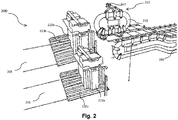
- an exemplary denesting apparatus 200 having a single closed loop conveying track 230 for denesting one or more stacks of sheets 210 , including a first stack 210a positioned onto a first stacking magazine 220a , and a second stack 210b positioned onto a second stacking magazine 120b, onto an out-feed conveyor 280.
- the closed loop conveying track 230 includes a plurality of sets of one or more de-stacking means 240 movingly configured thereon through a de-stacking means moving mechanism 250.
- the de-stacking means moving mechanism 250 includes a plurality of de-stacking lugs 252 ( Figs 5A , 5b ), each movingly configured onto the closed loop conveying track 230 through a de-stacking mover 254 ( Figs 5A , 5b ). Further, each of the de-stacking lugs 252 is adapted to engage to at least one of the sets of de-stacking means 240 through an engagement means 255 ( Fig. 5a ).
- the engaging means 255 includes an articulating engagement assembly 270 movingly engage one of the sets of one or more de-stacking means 240 onto one or more de-stacking lugs 252.
- each set of the one or more de-stacking means 240 is positioned onto a supporting plate 242 , having a first side 242a connected to a pair of de-stacking movers 254a , 254b , pivotally and movably attached to each other through one or more articulated mounting brackets 272.
- the articulated bracket 272 is a conventionally known mounting bracket and includes a first attachment bracket 274 connected to a second attachment bracket 276 at their distal ends at a connection point C such that the articulated bracket has three open ends, i.e. a first open end 274a at a proximal end of the first attachment bracket 274 , a second open end 276a at the proximal end of the second attachment bracket 276 and a pivotally movable center end 275 at the connection point C.
- the articulated movement assembly 270 includes a first de-stacking mover 254a connected to a second de-stacking mover 254b through the articulated mounting brackets 272 , each of the movers 254a , 254b connected at one of the open ends 274a , 274b of the articulated bracket 272 , such that the articulated bracket 272 is pivotally movable in a generally vertical plane throughout the longitudinal range of motion of the first mover 254a and the second movers 254b , towards and/or away from each other.
- the articulated assembly 270 is connected to the first side 242a of the supporting plate 242 at the pivotally movable center end 275 thereof.
- the supporting plate 242 In a collapsed position, where the articulated mounting bracket 272 is closed, such that each of the pair of pivotally connected de-stacking movers 254a, 254b are oriented in a substantially coinciding position, the supporting plate 242 is at its initial position. In an opened position, where the articulated mounting bracket 272 opens up pivotally, the pair of the movers 254a, 254b may be moved towards or away from each other such that the corresponding supporting plate 242 is moved vertically upward or pivotally towards or away from corresponding de-stacking lugs 252a, 252b.
- the articulated movement assembly 270 having the pair of movers 254a, 254b is pivotally connected for longitudinal movement in a generally horizontal plane in a conventional manner.
- the articulated movement assembly 270 is movingly supported on to the closed loop conveying track 230 such that a horizontal longitudinal movement of the movers 254a, 254b towards and away from each other is possible.
- Such a movement of the pair of movers 254a, 254b provides operative power for enabling the movement of the mounting bracket 272 between its collapsed position and its open position, thereby enabling a range of vertically upward and pivotal extensions along with a longitudinal movement of the shaping supporting plate 242 onto the closed loop conveying track 230.
- the supporting plate 242 and the corresponding set of de-stacking means 240 may be positioned at any desired distance away from the de-stacking lugs 252 , while moving in an operative orientation generally in a vertical and/or transversal and/or horizontal direction.
- the engagement means 255 may be any conventionally known mechanism suitable for supporting the set of one or more de-stacking means 240 onto the de-stacking lugs 252 and is selected from one or more of but not limited to a supporting plate as illustrated in Fig. 5b
- the denesting apparatus 200 includes multiple and preferably a pair of overhead closed loop conveying tracks 230 namely 230a, 230b for denesting one or more stacks 210 including a first stack 210a positioned onto a first stacking magazine 220a, and a second stack 210b positioned onto a second stacking magazine 220b.
- the individual movement of the sets of de-stacking means 240 of each of the tracks 230a, 230b may be utilized to speed up the process by utilizing either as a dedicated track 230 for predetermined stacks 210 or otherwise in situations where there is a need of simultaneously pick up and drop down of the sheets within stacks 210 onto the out-feed conveyor 280.
- de-stacking means 240 of both the tracks may be adapted to sequentially or simultaneously pick up the top sheet from the same stack 210.
- the sets of de-stacking means of the pair of tracks 230a , 230b may be utilized in any possible manner so as to de-stack one or more, stacks 210 , onto the out-feed conveyor 280.
- This embodiment is particularly advantageous due to the fact that it provides multiple closed loop conveying tracks 230 and therefore the de-stacking means 240 each powered by a single light weight powering means for managing the operation of the denesting apparatus 200 and therefore is considered as a further efficient way to implement various embodiments of the present invention.
- FIGS. 2 and 3 schematically show the arrangement of the basic components of the denesting apparatus 200 of the present invention.
- secondary components such as couplers, connectors, support structures and other functional components known to one of skill in the field of denesting apparatuses and more particularly the denesting of foldable blanks for use with conveyor systems, may be incorporated within the denesting apparatus 200.
- Such commercial arrangements are included in the present invention as long as the structural components and arrangements disclosed herein are present. Accordingly, it is to be contemplated that the denesting apparatus 200 may be configured to be used for any kind of foldable blank of any possible shapes as deems possible without deviating from the scope of the current invention.
- the one or more stacks of sheets 210 may be formed of a plurality of sheets in the form of foldable blanks, each adapted to form a primary or secondary package and/or a component thereof.
- the first stack 210a positioned onto the first stacking magazine 220a may be stack of plurality of blanks each adapted to form a box shaped secondary package.
- the second stack 210b positioned onto the second stacking magazine 220b may be a stack of plurality of partition sheets, each adapted to form a partition for the box shaped secondary package.
- the stack of sheets 210 may include any number of stacks of sheets, adapted to form any kind of output product, to be denested using the apparatus 200 of the present invention.
- Each of the stacking magazines 220a , 220b is connected to an incoming conveying line 205 each carrying a supply of stack of sheets 220a , 220b respectively.
- the stacking magazines 220 are generally vertically movable storage racks 222 adapted to move between a top position P T and a bottom position P B through a vertical movement mechanism 224.
- the top position P T is positioned at a height H T away from a base platform corresponding to the base position P B , such that the top sheet of the stack 210 is positioned at a height H S suitable to be picked up by at least one set of the de-stacking means 240.
- the vertical movement mechanism 224 includes a vertical rail (not shown) positioned besides the storage rack 222 having one or more stacking movers 226 movingly configured thereon, and adapted to engage the storage rack 222 using a connecting member (not shown) such that the storage rack 222 is movable between its top position P T and the bottom position P B through the stacking movers 226.
- the vertical movement mechanism 224 may be any suitable movement mechanism.
- the denesting apparatus 200 further includes a retractable lifting means 260 , illustrated in Figs 4a-4d positioned over each of the one or more stacking magazines 220 and adapted to support at least a sub-stack of the sheets, such that the top sheetis positioned at the height H S suitable to be picked up at least by one set of the de-stacking means 240 of the one or more closed loop conveying tracks 230.
- a retractable lifting means 260 illustrated in Figs 4a-4d positioned over each of the one or more stacking magazines 220 and adapted to support at least a sub-stack of the sheets, such that the top sheetis positioned at the height H S suitable to be picked up at least by one set of the de-stacking means 240 of the one or more closed loop conveying tracks 230.
- the retractable lifting means 260 is generally a flat lifting plate and is moveable vertically between a base position L BP and a top position L TP thereof, such that at any moment the top sheet is made to be positioned at the H S suitable to be picked up by at least one set of the de-stacking means 240. Further, the retractable means 260 is movable between an open position P O and a retracted position P R (not shown).
- Such lifting plate may alternatively also consist of a plurality of forks that may move away or towards each other
- the base position L BP of the retractable lifting means 260 is generally same as the top position P T of the storage rack 222 of the stacking magazine 220 such that when moved to open position P O from the retracted position P R , the retractable lifting means 260 supports the entire stack 210 thereon. Further, in such instances, the lifting means 260 moves vertically with removal of each top sheet to a distance same as a thickness of the sheet such that the top sheet is always positioned at the height H S , The top position L TP of the lifting means 260 is such that a bottommost sheet 215 ( Fig. 4d ) of the stack 210 is positioned as the top sheet. Once the stack 210 has been completely denested, lifting means 260 is adapted to retract back to the retracted position P R and vertically move down to the base position L BP .
- the out-feed conveyor 280 is generally an outgoing conveyor positioned substantially below the one or more closed loop conveying track 230 at a height H C from the base platform, substantially similar to the height H T of the top sheet such that the already pick up top sheet may be suitably dragged and/or dropped onto the out-feed conveyor 280 for further processing.
- the denesting apparatus 200 further includes a first powering means (not shown) for enabling a movement of the one or more closed loop conveying tracks 230 , the in-feed conveyor 205 , each of the one or more stacking magazines 220 , the retractable lifting mechanism 260 , the out-feed conveyor 280 and various sub-components thereof.
- a first powering means (not shown) for enabling a movement of the one or more closed loop conveying tracks 230 , the in-feed conveyor 205 , each of the one or more stacking magazines 220 , the retractable lifting mechanism 260 , the out-feed conveyor 280 and various sub-components thereof.
- the first powering means is a linear servo motor adapted to move each of the one or more closed loop conveying tracks 230 , the in-feed conveyor 205 , each of the one or more stacking magazines 220 , the retractable lifting mechanism 260 , the out-feed conveyor 280 at a first predetermined pitch facilitating a continuous operation of each of the components of the denesting apparatus 200 such that the incoming supply of the stacks of sheets 210 is continuously denested and transferred onto the out-feed conveyor 280 in any desired order and in any desired manner.
- the first powering means is a linear servo motor adapted to move each of the one or more closed loop conveying tracks 230 , the in-feed conveyor 205 , each of the one or more stacking magazines 220 , the retractable lifting mechanism 260 , the out-feed conveyor 280 at a dynamically adjustable variable pitch facilitating an intermittent operation of each of the components of the denesting apparatus 200 such that the incoming supply of the stacks 210 of the sheets is denested and transferred onto the out-feed conveyor 280 , intermittently and when desired.
- the denesting apparatus 200 further includes a second powering means (not shown) for enabling a movement of each of the movers including, the de-stacking movers 254 , and the stacking movers 226 along the corresponding tracks and/or rails.
- the first powering means is linear servo motor.
- the linear motor is a generally moving magnet type of motor conventionally known in the art. Further in such embodiments, the linear motor utilizes the corresponding tracks and/or rails as a stator and each of the movers as a rotor thereof.
- the movers 254, 226 are utilized as stator whereas the tracks or rails are utilized as the rotors.
- each of the movers 254, 226 may include built in coils and each of the corresponding tracks or rails may include magnets configured thereon in a longitudinal direction such that the movers are able to come into an electromagnetic interaction, thereby enabling a movement thereof.
- the denesting apparatus 200 may further include one or more control units (not shown) for managing the operations thereof, and particularly for managing the working of the first powering means and/or the second powering means and more particularly the movement of the de-stacking movers 254a and b, so as to optimize the sequence of the longitudinal and/or vertical and/or transversal movement of the supporting plate 242 , and therefore the one or more support pads 240 , in a predetermined sequence.
- the predetermined sequence is particularly required to be evaluated in the instances where a specific predetermined order has to be followed for picking up the top sheets 211 , from the one or more stacks 210.
- control unit may include an input unit for receiving inputs related to the predetermined order of denesting the stacks 210 and the desired manner of discharge of the already picked up top sheets 211 , onto the out-feed conveyor 280. Further, the control unit may include a plurality of sensors (not shown) for tracking the parameters such as for example, position, width and/or height of the of the sheets or blanks to be discharged, for sensing when the one or more stacks 210 is empty, for sensing if the lifting means reached its top position, and the like.
- the control unit may further include a processor unit for processing the data captured by the input unit on the basis of predetermined logics / rules for facilitating the movement of the plurality of movers 254 , 226 , the vertical movement of the stacking magazine 220 , and the retractable lifting mechanism 260.
- the control unit may further include an instruction unit that delivers the instructions to various components such as various powering means, linear motors, motors, driving units, or the like, to facilitate a desired and smooth operation.
- control unit may be provided as a computer program product, such as may include a computer-readable storage medium or a non-transitory machine-readable medium maintaining instructions interpretable by a computer or other electronic device, such as to perform one or more processes.
- each of the plurality of sheets of the stack 210 is generally formed from a recyclable material selected from one or more of but not limited to any desired material such as including all kind of papers, fiberboard, corrugated board, foldable blanks, hybrid material, or any combinations thereof. Further, the shape and size, including the thickness of the sheets or blanks , may be varied depending on the design constraints and requirements for its application. In some other embodiments, the sheets or blanks may be made of a light weight plastic material selected from one or more of, but not limited to, plastic material such as group of thermoplastics including acetal, acrylic, cellulose acetate, polyethylene, polystyrene, vinyl, and nylon. In yet other embodiments, the sheets or blanks may be made of any material suitable to be denested using the denesting apparatus 200 , of the present invention
- the one or more de-stacking means 240 is formed of a conventionally known suction cup and/or vacuum cup having a generally bell-shaped structure and formed of a generally soft material such as a rubber, silicon, and the like, that is impenetrable by air.
- a de-stacking means 240 has been vastly utilized for lifting an object by application of vacuum created there within, when applied with a force against a flat surface such as a sheet.
- the number, size, and dimension of such de-stacking means 240 is determined on the basis of weight, dimensions, and material of the sheets or blanks to be picked up from the stack 210.
- the denesting apparatus 200 may further be provided with a supply of negative pressure, for example, in the form of a vacuum creator, which may be utilized by de-stacking means 240 for picking such heavy sheets.
- the present invention may be utilized for any number of stacks without deviating from the scope of disclosure and depending upon the design constraints of the package to be formed.
- the one or more stacks 210 may include a first stack 210a of foldable blank of carton, a second stack 210b of a partition for the carton, a third stack 210c holding sheet for forming a handle of the carton and so on.
- the denesting apparatus 200 may be used to denest only a single stack 210. In all such embodiments, the number of stacking magazines 220 remains equal to number of stacks 210 so as to individually support the stacks 210 thereon.
- each of the conveyors of the denesting apparatus 200 including the one or more closed loop conveying tracks 230 , the in-feed conveyor 205 , and the receiving conveyor 280 is generally a vertically positioned closed loop conveying track conventionally known in the art.
- each of the conveyors of the denesting apparatus 200 including the one or more closed loop conveying tracks 230 , the in-feed conveyor 205 , and the out-feed conveyor 280 may be a generally horizontal positioned closed loop conveying track.
- each of the conveyors of the denesting apparatus 200 including the one or more closed loop conveying tracks 230 , the in-feed conveyor 205 , and the receiving conveyor 280 may be configured as a virtual closed loop conveyor.
- the virtual closed loop conveyor is generally a closed loop conveyor similar to a circular conveyor, in which the circular connecting edges of the conveyors on both the ends are replaced by straight shiftable conveyor portions adapted to move back and forth and avoiding the need of moving the movers through the entire circumference of the closed loop conveying track, and is therefore a very fast alternative to the conventionally known closed loop conveying tracks.
- the closed loop conveyor being made of longitudinal rails, is therefore much more cost efficient than any conventionally known closed loop conveying tracks and/or conveyors. Additionally, the back and forth movement may also be helpful in providing additional pressure while performing operations such as pushing operation is therefore further preferred.
- the stacking magazine 220 may be a horizontal conveyor (not shown) adapted to receive a supply of stacks 210 of the sheets or blanks such that the top sheet of one of the stack 210 is positioned at a distance suitable to be picked up by the one or more de-stacking means 240. Further, once the stack 210 is exhausted, another stack 210 is positioned at the distance suitable to be picked up by the one or more de-stacking means 240 such that there is no interruption there between.
- the denesting apparatus 200 is adapted to be positioned onto an input line of a package manufacturing unit provided with one or more stacks 210 of foldable blanks for forming generally box shaped secondary packages.
- the denesting apparatus 200 denests the foldable blanks from the one or more stacks 210 placed onto the one or more stack magazines 220 in any predetermined order and places onto the out-feed conveyor 280 in any desired manner.
- Each of the stacks 210 is denested in a generally top to bottom manner, however, not restricted to any particular way of denesting and therefore it is contemplated that the denesting apparatus of the present invention may be utilize to perform denesting operation in any possible way without deviating from the scope of the present invention.
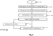
- Fig. 6 is a flow diagram illustrating a method 600 of de-stacking sheets or blanks from one or more stacks 210 thereof placed onto one or more stacking magazines 220 , either simultaneously, or otherwise sequentially in any desired manner, either one besides other or otherwise in an overlapping manner, using denesting apparatus 200 of the present invention.
- the method 600 starts at step 602 and proceeds to step 604 where one or more stacks 210 of sheets is received onto one or more stacking magazines 220.
- the one or more stacking magazines 220 is positioned generally at a distance from the one or more overhead closed loop conveying tracks 230 such that the top sheet of each of the stacks 210 is positioned at the height H S and at a distance suitable to be picked up by at least one of the set of de-stacking means 240 of the one or more closed loop conveying tracks 230.
- the steps proceed to step 606 , where the one or more sets of de-stacking means 240 picks up at least one of the top sheets 211 from at least one of the stacks 210.
- the one or more sets of de-stacking means 240 is adapted to pick up one or more top sheets 211 from the one or more stacks 210 sequentially in any possible order.
- the one or more sets of de-stacking means 240 of the one or more closed loop conveying tracks 230 is adapted to pick one or more top sheets 211 from the one or more stacks 210 simultaneously at the same time.
- each of sets of the de-stacking means 240 is adapted to pick up the top sheet from the one or more stacks 210 independently of the other sets of de-stacking means 240.
- step 608 each of the stacking magazine 220 is made ready to be denested such that the top sheet of the each of the stack 210 is positioned at the height H S suitable to be picked up by at least one of the set of de-stacking means 240 of the one or more closed loop conveying tracks 230.
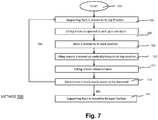
- Such a step involves multiple sub-steps and is described in flow chart as illustrated in Fig. 7 , as a method 700 for keeping each of the stacks 210 ready for being denested and will be described later on.
- each of the set of de-stacking means 240 discharges the already picked up sheets 211 , by placing and/or dropping it onto the out-feed conveyor 280 in any desired manner.
- the one or more sets of de-stacking means 240 is adapted to drop the picked up top sheets 211 sequentially one besides other in any possible arrangement.
- the one or more sets of de-stacking means 240 is adapted to drop the picked-up sheets 211 sequentially one over the other in an overlapping manner.
- the one or more sets of the de-stacking means 240 of the one or more closed loop conveying track 230 is adapted to drop the picked-up sheets 211 simultaneously one besides other in any possible arrangement.
- the one or more sets of de-stacking means 240 of the one or more closed loop conveying tracks 230 is adapted to drop the picked-up sheets 211 simultaneously one over the other in an overlapping manner.
- each of the set of de-stacking means 240 is adapted to drop up the picked-up sheets 211 independently of the other de-stacking means 240 in any desired order and in any desired manner.
- the method 600 further includes an optional step 609 of rotating the picked-up sheets 211 before dropping onto the out-feed conveyor 280 at step 610.
- the supporting plate 242 in such embodiments is adapted to be rotated horizontally in a range of angles so as to rotate the picked-up sheet 211 at any desired angle before being dropped onto the out-feed conveyor 280.
- the method 700 as illustrated in Fig. 7 for preparing each of the one or more vertically movable stacking magazines 220 with the one or more stacks 210 positioned in such a way that the top sheet is always positioned at the height H S suitable to be picked up by at least one of the set of de-stacking means 240 of the one or more closed loop conveying tracks 230.
- the method starts at step 702 and proceeds to step 704 where the vertically movable supporting rack 222 is moved to its top position P T as illustrated in Fig. 4a .
- the method then proceeds to step 706 where the retractable lifting means 260 , vertically positioned anywhere between its base position L BP and the top position L TP , is moved to its open position P O such that at least a sub-stack 214 gets supported thereon the lifting means 260 as illustrated in Fig. 4a , 4b .
- the lifting means 260 is opened at its base position L BP , such that the entire stack 210 is supported onto the lifting means 260.
- the vertically movable supporting rack 222 moves back to its base position P B and may be replenished there at by the incoming conveying line 205 as illustrated in Fig. 4c .
- the retractable lifting means 260 vertically moves up till it reaches its top position L TP such that the bottom most sheet 215 is positioned as the top sheet as illustrated in Fig. 4d .
- Such a vertical movement of the lifting means 260 is synchronized with the removal of the top sheet and is therefore moved vertically each time the top sheet is removed, and to a distance same as the thickness of the sheet 290 so as to assure that the top sheet is always positioned at the height H S , Thereafter, at step 712 when the lifting means 260 is exhausted, retracts back to its retracted position P R and moves vertically downwards to its base position L BP .
- the method 700 further includes a step 714 performed in parallel to the step 712 where the supporting rack 222, replenished with new stack 210 moves vertically upwards till it reaches its top position P T such that there is no interruption within the denesting operation of de-stacking means 240.
- step 714 the method 700 checks if there are more stacks to be denested, and if yes, loops back to step 706 and is repeated until there are more stacks to be denested. If, however no further stacks are to be denested, the storage rack 222 moves to its base position P B and kept in a suspended state.
- the present invention relates to a denesting apparatus 200 for continuously and/or intermittently at a constant and/or variable speed, de-stacking sheets individually from one or more stacks in any desired order and discharging them onto an out-feed conveyor in any desired manner.
- the denesting apparatus 200 is adapted to receive a supply of stacks 210 of foldable blanks in form of sheets , from an incoming conveying line 205 , adapted to continuously fill any of the already exhausted stacks 210 such that there are no interruptions during refilling the stacking magazines 220 with new stacks 210.
- the possibility of providing different kind of pushing sequence to the one or more sets of de-stacking means 240 allows picking up the top sheets 211 in any desired order and discharging in any desired manner.
- Such an optimized and focused picking up and dropping down the sheets in addition to a complete control of the speed, direction of the placement of the sheets allows the possibility of using a same conveying line for discharging multiple sheets together while utilizing the width of the out-feed conveyor and avoiding misalignment and therefore, any damage to the sheets being discharged there through.
- the present invention is additional advantageous in providing an input line of packaging apparatus of different sub-parts of the packages, in accordance with the predetermined shape and configurations of the packages to be achieved.
- the denesting tool is adaptable to different dimensions of foldable blanks and is therefore well suitable to process packages of different sizes and shapes with ease and efficiently and not requiring changing the entire apparatus for denesting sheets of different predetermined shapes and sizes.
- the present invention provides the possibility of manufacturing the conveyor system with integrally formed denester apparatus 200.
- Such a conveyor system for forming secondary package while being cost-efficient, is very quick and easy to use and offers comfortable handling of packages of any shape, size or any variety of configurations.
- a single conveyor system may utilize as many as denesting apparatuses within the same arrangement. Further, in case of one denesting apparatus is not working, rest can keep working and therefore, the fault tolerance of the plant can be increased.
- denesting apparatus 200 of present invention has been disclosed with reference to foldable blanks, it may be used to denest all currently known sheet types, e.g., constructed of materials such as thermoplastic, hybrid materials, woven metallic fabric that may include ferrous or nonferrous metals, etc., or any other suitable material. Even in instances where heavy sheets are to be picked up, the strength or number of de-stacking means 240 may be adapted in accordance without having to change the entire apparatus 200.
- the denesting apparatus 200 of the present invention may be implemented in various industries such as food industry, transport industry, house hold appliance industry in denesting of any kind of product or group of products, of any shape, size or any variety of configurations, without limiting it to the packaging industry.
Landscapes
- Engineering & Computer Science (AREA)
- Mechanical Engineering (AREA)
- Sheets, Magazines, And Separation Thereof (AREA)
Abstract
The present invention provides a denesting apparatus (100), the apparatus comprising:- one or more closed loop conveying tracks (130, 230), each closed loop conveying track comprising a plurality of sets of one or more de-stacking means movingly configured thereon through one or more de-stacking means moving mechanism;- one or more stacking magazines (120, 220), each adapted to hold a stack of sheets (110, 210) supported thereon;wherein each of the plurality of sets of de-stacking means (240) is adapted to selectively engage an uppermost sheet from at least one of the stacking magazines in any desired order either sequentially and/or simultaneously so as to discharge the picked-up sheets onto an out-feed conveyor in any desired manner either one besides another or otherwise one overlapping the other.
Description
- The present invention relates generally to a denesting apparatus for denesting one or more stacks of sheets.
- In the recent years, there has been a many-fold increase in the trend of grouping large number of items such as food items, including liquid foods, home essentials, stationary items, beverage containers, and the like, in the form of secondary packages, for various purposes such as to enable bulk selling, easy transportation, handling, and the like.
- Recently there has been a considerable increase in use of cardboard based packaging for holding liquid foods and beverages which resulted in an increase in the manufacture of cardboard packaging or cartons in a variety of shapes and sizes.
- Cardboard based packaging is generally formed of foldable blank or sheets, received generally from one or more stacks and therefore, during the packaging manufacturing process, it is required to sequentially and individually de-stack or unstuck these blanks or sheets from the stacks thereof which are then fed on to a packing line for formation of various kind of packaging.
- Conventionally, the step of de-stacking of these blanks or sheets has been performed by utilizing various kind of pickers such as for example, manipulators, which may also take the form of robots and/or robotic arms, adapted to pick up a top sheet from the stack intermittently. Unfortunately, such pickers are often not cost-efficient and have a high turn-around time and therefore do not reconcile well at instances where a continuous in-feed of these sheets at a high speed is required.
- Accordingly, numerous efforts have been imparted to produce tools that de-stack sheets from the stacks individually, sequentially and at a high speed. Examples include various mechanical assemblies including so called fingers and/or grippers adapted to lift and/or pull away either the uppermost or lowermost sheet from the stack. However, these fingers and grippers based pulling mechanisms were generally adapted to pull either a fixed size sheet or at least having similar shape and/or size convenient to be handled by such fingers or grippers. Additionally, such devices may result in high rates of rejection since the sliding contact of these pulling devices frequently damages the sheets and therefore, were not preferred.
- While it is usually desirable to provide a system which de-stacks sheets of material as quickly as possible, it is also important that the same de-stacking apparatus may be utilized for a variety of shapes and sizes of sheets. To overcome the problems of mechanical assemblies, various kind of air-nozzle based de-stacking mechanisms were introduced.
- For example,
WO2008015347 discloses the use of a retractable blower member disposed generally perpendicularly to a stack of sheets so as to blow a jet of air onto the flat items thereby removing the top sheet from the stack thereof. - Similarly,
US20110229297 discloses a denesting apparatus having a product carrier plate including a pair of air nozzle assemblies operable to separate a tray from the stack of trays and force the tray against the product carrier plate such that movement of the product carrier plate can selectively discharge the separated tray. - However, these air nozzle-based side blowing mechanisms are generally not effective in un-stacking sheets having different thickness. Further, in most instances, these de-stacking mechanisms blew away more than one sheet, which is not acceptable particularly in an automated system.
- Therefore, various other solutions were tried out to denest the top sheet from stacks thereof. Recently, the trend has been shifting towards use of a variety of suction mechanisms for performing the denesting operation. These mechanisms generally utilize suction mechanisms either singly or in conjunction with air nozzles.
- For example,
EP1541508 discloses a device for the de-stacking of flat objects laid on a stack. The device has a suction device located above the stack support, and a pushing away device with pushing components. The suction device and pushing away device are located at a fixed distance above the stack support, and the pushing components on their end face facing the stack support during the pushing away of an object from the suction head of the suction device have a stop for the next object lifted from the stack by the suction head.US 3,401,831 discloses a denester which, in addition to the suction grippers, includes nozzles which blow pressurized air between the outermost tray and the tray immediately succeeding it, in order to facilitate their separation. Such suction mechanism utilizes suction heads/nozzles which further requires vacuum hoists/supply to create negative air pressure for suction. Therefore, these arrangements are often overly complex in design, and were also undesirably slow in their operation. - Recently, various kind of de-stacking means or cups-based mechanisms have been utilized due to their simple structure and designs. For example, as disclosed in
US5,254,071 , these mechanisms generally include a drive mechanism with a vacuum cup which is alternatively brought close, put into contact then moved away from the stack of sheets. The vacuum cup is laid against the top sheet of the stack and then carries away the top sheet to bring it away from the stack before laying it down on another work area, for example, on a packaging line conveyor. - In some other variations, de-stacking means were utilized to pick the sheet/tray from bottom as described in
US20140056684 which discloses a tray denesting apparatus presenting stacks of trays placed upside down within a storage area to a picker mechanism and separating single trays from the stack of trays. A de-stacking means is used to remove individual trays from the tray stack. After picking up the individual tray, a driven rotary device inverts the tray and places the tray onto a tray conveyor located beneath the denesting apparatus. - However, all such packaging apparatuses have certain shortcomings as well. Firstly, these de-stacking means based mechanisms utilize drive mechanisms adapted to pick up and denest the sheets in accordance to a predetermined distance setting from a predetermined stack. Such system is, however, not designed for cases where a same packaging is a combination of different kind of sheets, such as e.g. a package blank combined with a partition blank.
- Secondly, when a particular stack is exhausted, it is necessary to temporary suspend the denesting operation while the stack is replenished. As a result, the continuous supply of the sheets to the packaging line is interrupted and therefore reduces productivity of these packaging lines. Further, in automatic conveying lines these interruptions have to be managed with various compensating tools or mechanisms which further hugely impacts the costs and is therefore not preferred.
- Accordingly, as can be understood from the foregoing discussion, none of the existing solutions completely provides flexibility of varying the de-stacking operation in accordance to varying requirements of multiple stacks simultaneously while preventing suspending the operation. Thus, in the context of the above, it is desirable to provide a denesting device that overcomes these problems associated with the prior art, is inexpensive to manufacture, and allows to carry out de-stacking of multiple stacks of different sheets of varying configurations in various desired manner, without requiring to change any functional elements thereof.
- In one aspect of the invention, a denesting apparatus for denesting sheets of foldable blanks from one or more stacks thereof is provided. The denesting tool includes one or more closed loop conveying tracks comprising a plurality of sets of de-stacking means movingly configured thereon through a de-stacking means moving mechanism. The denesting apparatus further includes one or more stacking magazines each adapted to hold a stack of sheets to be denested. In operation, each of the plurality of sets of de-stacking means is adapted to selectively engage an uppermost sheet from at least one of the stacking magazines and discharge it onto an out-feed conveyor. The picking up of the sheets from the one or more stacks may be performed in any desired order either sequentially or otherwise simultaneously so as to discharge the picked-up sheets in any desired manner either one besides another or in an overlapping manner i.e. one over the other.
- Generally, the de-stacking means may be a conventionally known suction cup and/or vacuum cup having a generally bell-shaped structure and formed of a generally soft material such as a rubber, silicon, and the like, that is impenetrable by air.
- Optionally, the de-stacking means moving mechanism includes a plurality of de-stacking lugs, each adapted to movingly engage one of the sets of one or more de-stacking means through an engagement means.
- Further optionally, each of the de-stacking lugs is movingly configured onto one of the closed loop conveying tracks through one or more de-stacking movers movingly configured thereon.
- In a specific embodiment, the denesting apparatus comprises two parallel closed loop conveying tracks wherein the de-stacking means moving mechanism includes a plurality of de-stacking lugs movingly configured onto the parallel closed loop conveying tracks through one or more de-stacking movers movingly configured thereon and wherein the de-stacking movers on the parallel closed loop conveying tracks are independently controlled to achieve rotation of the picked-up sheet.
- Possibly, the engagement means may be any conventionally known mechanism suitable for supporting one or more de-stacking means onto the de-stacking lugs and is selected from one or more of, but not limited to, a supporting plate. Alternatively, the engagement means includes an articulating engagement assembly for movingly engage one of the sets of one or more de-stacking means onto the one or more de-stacking lugs, and adapted to provide generally a vertical and/or transversal movement along with a longitudinal movement, enabling a picking up a sheet from one of the stacking magazines.
- Possibly, the articulating engagement assembly includes an articulated bracket having a first end connected to a first de-stacking mover through a first de-stacking lug, a second open end connected to a second de-stacking mover through a second de-stacking lug and a pivotally movable center end connected to a supporting plate having one or more de-stacking means configured thereon, such that a longitudinal movement of the de-stacking movers towards and/or away from each other enables a generally vertical movement to the supporting plate and in turn to the one or more de-stacking means so as to pick up a sheet positioned at a distance thereto.
- Further possibly the supporting plate is a generally horizontally rotatable plate facilitating rotation of the sheet picked up by the one or more de-stacking means.
- Optionally, the one or more stacking magazine is a vertically movable supporting rack adapted to move between a top position PT and a bottom position PB using a vertical movement mechanism.
- Further optionally, the vertical movement comprising a vertical rail comprising one or more stacking movers movingly configured thereon and each of the stacking movers engaging the supporting rack using a connecting member such that the stacking member is movable between the top position PT and the bottom position PB through the stacking movers.
- Alternatively, the vertical movement mechanism may be any suitable movement mechanism.
- Possibly, the top position PT of the stacking magazine is positioned at a height HT away from a base platform, corresponding to the base position PB, such that a top sheet of the stack is positioned at a height HS suitable to be picked up by at least one of set of the de-stacking means.
- Generally, the denesting apparatus further includes a retractable lifting means positioned over the one or more stacking magazine and adapted to support at least a sub-stack of sheets such that the top sheet of the corresponding sub-stack is positioned at the height HS suitable to be picked up by at least one of the de-stacking means.
- Further, the retractable lifting means is adapted to be vertically movable such that after removal of the top sheet, the next top sheet is always positioned at the height HS suitable to be picked up by the one or more de-stacking means.
- Furthermore, the retractable lifting means is configured to retract back and move back to its base position, once each of the sheets supported thereon is picked up by the one or more de-stacking means.
- Additionally, the retractable lifting means is further configured to open and pick up another sub-stack of the sheets at its base position.
- Possibly, the apparatus further includes an infeed conveying line connected to the one or more stacks such that as soon as an empty magazine is received at its bottom position, it gets replenished with new stack of sheets.
- Optionally, the stacking magazine may be a horizontally moving conveyor.
- Optionally, the one or more closed loop conveying tracks, the lifting plate, and the one or more stacking magazines are adapted to move at a predetermined pitch so as to denest the stacks of the one or more sheets onto the out-feed conveyor continuously.
- Alternatively, the one or more closed loop conveying tracks, the lifting plate, and the one or more stacking magazines are adapted to move intermittently at a variable pitch as required, so as to denest the stacks of the one or more sheets onto the out-feed conveyor intermittently.
- Preferably, the vertical movement of the stacking magazine is configured in such a way that when the lifting plate is in its retracted position, the stacking magazine is in its top position such that the top sheet is positioned at the height HS suitable to be picked up by the one or more de-stacking means.
- Optionally, the denesting apparatus includes a first powering means enabling a movement of each of the one or more closed loop conveying tracks, the infeed conveyor, the retractable lifting means, the stacking magazine and the out-feed conveyor.
- Further optionally, the first powering means may be selected from one or more of but not limited to various conventionally known linear motors, asynchronic motors, machines, servo drives, and the like conventionally known in the art.
- Possibly, each of the plurality of movers is individually powered by a second powering means, preferably a linear motor, utilizing each of the movers as a rotor thereof and the corresponding track as a stator thereof.
- Alternatively, the second powering means may be selected from one or more of, but not limited to, various conventionally known asynchronic motors, machines, servo drives, and the like, conventionally known in the art.
- Particularly, the sheet of foldable blank is formed of a material selected from one or more of, but not limited to, a carton, paperboard, thermoplastic, hybrid material, and the like.
- Possibly, the denesting apparatus further comprises a control unit for optimizing the movement of the one or more closed loop conveying tracks, the one or more de-stacking means, the one or more stacking magazines, the retractable lifting means, and the incoming conveying line.
- Further possibly, the control unit includes one or more sensors, one or more input units, a processor unit and an output unit.
- In yet another aspect of the invention, a method of denesting one or more stacks of sheets, each supported onto a corresponding stacking magazine, using the denesting apparatus of the present invention, is provided. The method includes receiving one or more stacks of sheets of a predetermined material. The method further includes picking up a top sheet from the one or more stacks in a predetermined manner either sequentially or otherwise simultaneously. The method further includes placing the picked-up sheet onto the out-feed conveyor in any desired manner, either one besides the other or otherwise one over the other.
- Optionally, the method includes rotating the picked-up sheet before placing it onto the out-feed conveyor.
- Optionally, the step of picking up the one or more sheets from the one or more stack includes the step of contacting at least the one or more de-stacking means, with one of the stacks such that the top sheet of the stack is picked up by the corresponding de-stacking means.
- Optionally, the method includes picking one sheet at a time sequentially.
- Alternatively, the method includes picking more than one sheet at a time simultaneously.
- Further alternatively, the method includes dropping the simultaneously picked up sheet either simultaneously one besides other or otherwise sequentially one over the other.
- Possibly, the method includes moving the each of the one or more or more pair of de-stacking lugs together in a predetermined sequence of vertical movement and/or transversal movement and/or longitudinal movement, so as to position the corresponding de-stacking means in contact with the top sheet of the desired stack of sheet.
- Further possibly, the pushing sequence is determined by the control unit on the basis of an input from a user and/or input from one or more sensors.
- Other aspects, features and advantages of the subject matter disclosed herein will be apparent from the description, the drawings, and the claims.
-
-
FIG. 1 illustrates a schematic diagram representing a denesting apparatus, in accordance with a preferred embodiment of the present invention; -
FIG. 2 illustrates a schematic diagram representing an exemplary denesting apparatus, in accordance with a preferred embodiment of the present invention; -
FIG. 3 illustrates a schematic diagram representing another exemplary denesting apparatus, in accordance with another preferred embodiment of the present invention; -
FIGS. 4a ,4b ,4c ,4d illustrate a front view diagram representing the exemplary denesting apparatus at different steps, in accordance with a preferred embodiment of the present invention; -
FIG. 5a illustrates a perspective view diagram representing an exemplary engaging means, in accordance with the preferred embodiment of the present invention; -
FIG. 5b illustrates a perspective view diagram representing another exemplary engaging means, in accordance with another embodiment of the present invention; -
FIG. 6 depicts a flowchart illustrating the method for denesting sheets from one or more stacks, in accordance with an embodiment of the present invention; and -
FIG. 7 depicts a flowchart illustrating the method steps of making each of the stacks ready for denesting operation, in accordance with an embodiment of the present invention. - The present application discloses a denesting apparatus, for picking up sheets individually from one or more stacks in any desired order and discharging them onto an out-feed conveyor in any desired manner. The denesting apparatus while being efficient, is able to destack sheets from multiple stacks having sheets of different shapes, sizes and material without requiring any changes in the functional elements thereof. Further, the sheets may be picked up either simultaneously or otherwise sequentially and may be discharged on to an out-feed conveyor, placed either one besides another or otherwise one over another, either continuously or otherwise intermittently and in varying configurations, speeds, and the like, without requiring making any change within the apparatus.
- As illustrated in
FIG. 1 , the present invention provides adenesting apparatus 100 for de-stacking one or more stacks of sheets or b110 individually and dropping them onto an out-feed conveyor 180. - The
denesting apparatus 100 includes one or more overhead closedloop conveying tracks 130 comprising a plurality of sets of de-stacking means 140 movingly configured thereon, through a de-stacking means movingmechanism 150. Thedenesting apparatus 100 further includes one or more stackingmagazines 120, each adapted to support one of the one or more stacks ofsheets 110. Further, each of the stackingmagazines 120 is connected to an incoming conveying line (not shown) carrying a supply of stacks ofsheets 110. Thedenesting apparatus 100 furthermore includes aretractable lifting mechanism 160 adapted to support at least a sub-stack of the stack ofsheets 110 such that a top sheet is positioned at a height suitable to be picked up by at least one of the sets of de-stacking means 140. In operation, the one or more stacks ofsheets 110 are first positioned onto the one or more stackingmagazines 120. Thereafter, one or more sets of the de-stacking means 140 is movingly positioned towards the one of the one ormore stacks 110 such that the top sheet from at least one of the stackingmagazines 120 is picked up in any desired order, and discharged towards the out-feed conveyor 180 in any desired manner. - In description of the
FIGS. 2-3 that follow, elements common to the schematic system will have the same number designation unless otherwise noted. In a first preferred embodiment, as illustrated inFig. 2 , anexemplary denesting apparatus 200 having a single closedloop conveying track 230 for denesting one or more stacks ofsheets 210, including afirst stack 210a positioned onto a first stackingmagazine 220a, and asecond stack 210b positioned onto a second stacking magazine 120b, onto an out-feed conveyor 280. - The closed
loop conveying track 230 includes a plurality of sets of one or more de-stacking means 240 movingly configured thereon through a de-stacking means movingmechanism 250. The de-stacking means movingmechanism 250 includes a plurality of de-stacking lugs 252 (Figs 5A ,5b ), each movingly configured onto the closedloop conveying track 230 through a de-stacking mover 254 (Figs 5A ,5b ). Further, each of the de-stacking lugs 252 is adapted to engage to at least one of the sets of de-stacking means 240 through an engagement means 255 (Fig. 5a ). In a preferred embodiment of the present invention, the engaging means 255 includes an articulatingengagement assembly 270 movingly engage one of the sets of one or more de-stacking means 240 onto one or more de-stacking lugs 252. In such an embodiment, each set of the one or more de-stacking means 240 is positioned onto a supportingplate 242, having afirst side 242a connected to a pair ofde-stacking movers brackets 272. The articulatedbracket 272 is a conventionally known mounting bracket and includes a first attachment bracket 274 connected to a second attachment bracket 276 at their distal ends at a connection point C such that the articulated bracket has three open ends, i.e. a firstopen end 274a at a proximal end of the first attachment bracket 274, a second open end 276a at the proximal end of the second attachment bracket 276 and a pivotallymovable center end 275 at the connection point C. - Further, as illustrated in
Fig.5a , the articulatedmovement assembly 270 includes a firstde-stacking mover 254a connected to a secondde-stacking mover 254b through the articulated mountingbrackets 272, each of themovers bracket 272, such that the articulatedbracket 272 is pivotally movable in a generally vertical plane throughout the longitudinal range of motion of thefirst mover 254a and thesecond movers 254b, towards and/or away from each other. The articulatedassembly 270 is connected to thefirst side 242a of the supportingplate 242 at the pivotallymovable center end 275 thereof. - In a collapsed position, where the articulated mounting
bracket 272 is closed, such that each of the pair of pivotally connectedde-stacking movers plate 242 is at its initial position. In an opened position, where the articulated mountingbracket 272 opens up pivotally, the pair of themovers plate 242 is moved vertically upward or pivotally towards or away from corresponding de-stacking lugs 252a, 252b. - One skilled in the art will recognize that the articulated
movement assembly 270 having the pair ofmovers movement assembly 270 is movingly supported on to the closedloop conveying track 230 such that a horizontal longitudinal movement of themovers movers bracket 272 between its collapsed position and its open position, thereby enabling a range of vertically upward and pivotal extensions along with a longitudinal movement of theshaping supporting plate 242 onto the closedloop conveying track 230. - Therefore, by appropriate manipulation of the
first mover 254a and thesecond mover 254b and therefore the articulatedassembly 270, the supportingplate 242 and the corresponding set of de-stacking means 240 may be positioned at any desired distance away from the de-stacking lugs 252, while moving in an operative orientation generally in a vertical and/or transversal and/or horizontal direction. - In yet other embodiments, the engagement means 255 may be any conventionally known mechanism suitable for supporting the set of one or more de-stacking means 240 onto the de-stacking lugs 252 and is selected from one or more of but not limited to a supporting plate as illustrated in
Fig. 5b - In a modification of the first embodiment, as illustrated in
FIG. 3 , thedenesting apparatus 200 includes multiple and preferably a pair of overhead closedloop conveying tracks 230 namely 230a, 230b for denesting one ormore stacks 210 including afirst stack 210a positioned onto a first stackingmagazine 220a, and asecond stack 210b positioned onto a second stackingmagazine 220b. - In such an embodiment, the individual movement of the sets of de-stacking means 240 of each of the
tracks dedicated track 230 forpredetermined stacks 210 or otherwise in situations where there is a need of simultaneously pick up and drop down of the sheets withinstacks 210 onto the out-feed conveyor 280. In yet other embodiments, de-stacking means 240 of both the tracks may be adapted to sequentially or simultaneously pick up the top sheet from thesame stack 210. In yet other embodiments, the sets of de-stacking means of the pair oftracks stacks 210, onto the out-feed conveyor 280. - This embodiment is particularly advantageous due to the fact that it provides multiple closed
loop conveying tracks 230 and therefore the de-stacking means 240 each powered by a single light weight powering means for managing the operation of thedenesting apparatus 200 and therefore is considered as a further efficient way to implement various embodiments of the present invention. -
FIGS. 2 and3 schematically show the arrangement of the basic components of thedenesting apparatus 200 of the present invention. However, in the construction of commercial functional units, secondary components such as couplers, connectors, support structures and other functional components known to one of skill in the field of denesting apparatuses and more particularly the denesting of foldable blanks for use with conveyor systems, may be incorporated within thedenesting apparatus 200. Such commercial arrangements are included in the present invention as long as the structural components and arrangements disclosed herein are present. Accordingly, it is to be contemplated that thedenesting apparatus 200 may be configured to be used for any kind of foldable blank of any possible shapes as deems possible without deviating from the scope of the current invention. - In a preferred embodiment, the one or more stacks of
sheets 210 may be formed of a plurality of sheets in the form of foldable blanks, each adapted to form a primary or secondary package and/or a component thereof. For example, and as illustrated inFig 2 , thefirst stack 210a positioned onto the first stackingmagazine 220a may be stack of plurality of blanks each adapted to form a box shaped secondary package. Further, thesecond stack 210b positioned onto the second stackingmagazine 220b may be a stack of plurality of partition sheets, each adapted to form a partition for the box shaped secondary package. However, in other embodiments, the stack ofsheets 210, may include any number of stacks of sheets, adapted to form any kind of output product, to be denested using theapparatus 200 of the present invention. Each of the stackingmagazines line 205 each carrying a supply of stack ofsheets - In an embodiment and referring to
Figs 4a-4d , the stackingmagazines 220 are generally verticallymovable storage racks 222 adapted to move between a top position PT and a bottom position PB through avertical movement mechanism 224. The top position PT is positioned at a height HT away from a base platform corresponding to the base position PB , such that the top sheet of thestack 210 is positioned at a height HS suitable to be picked up by at least one set of the de-stacking means 240. - Further in such embodiments, in preferred instances, as illustrated in
Fig. 4 , thevertical movement mechanism 224 includes a vertical rail (not shown) positioned besides thestorage rack 222 having one or more stackingmovers 226 movingly configured thereon, and adapted to engage thestorage rack 222 using a connecting member (not shown) such that thestorage rack 222 is movable between its top position PT and the bottom position PB through the stackingmovers 226. - However, in other instances, the
vertical movement mechanism 224 may be any suitable movement mechanism. - The
denesting apparatus 200 further includes a retractable lifting means 260, illustrated inFigs 4a-4d positioned over each of the one or more stackingmagazines 220 and adapted to support at least a sub-stack of the sheets, such that the top sheetis positioned at the height HS suitable to be picked up at least by one set of the de-stacking means 240 of the one or more closedloop conveying tracks 230. - In an embodiment, the retractable lifting means 260 is generally a flat lifting plate and is moveable vertically between a base position LBP and a top position LTP thereof, such that at any moment the top sheet is made to be positioned at the HS suitable to be picked up by at least one set of the de-stacking means 240. Further, the retractable means 260 is movable between an open position PO and a retracted position PR (not shown). Such lifting plate may alternatively also consist of a plurality of forks that may move away or towards each other
- In some instances, as illustrated in
Fig. 4a , the base position LBP of the retractable lifting means 260 is generally same as the top position PT of thestorage rack 222 of the stackingmagazine 220 such that when moved to open position PO from the retracted position PR , the retractable lifting means 260 supports theentire stack 210 thereon. Further, in such instances, the lifting means 260 moves vertically with removal of each top sheet to a distance same as a thickness of the sheet such that the top sheet is always positioned at the height HS , The top position LTP of the lifting means 260 is such that a bottommost sheet 215 (Fig. 4d ) of thestack 210 is positioned as the top sheet. Once thestack 210 has been completely denested, lifting means 260 is adapted to retract back to the retracted position PR and vertically move down to the base position LBP . - The out-
feed conveyor 280 is generally an outgoing conveyor positioned substantially below the one or more closedloop conveying track 230 at a height HC from the base platform, substantially similar to the height HT of the top sheet such that the already pick up top sheet may be suitably dragged and/or dropped onto the out-feed conveyor 280 for further processing. - The
denesting apparatus 200 further includes a first powering means (not shown) for enabling a movement of the one or more closedloop conveying tracks 230, the in-feed conveyor 205, each of the one or more stackingmagazines 220, theretractable lifting mechanism 260, the out-feed conveyor 280 and various sub-components thereof. In a preferred embodiment, the first powering means is a linear servo motor adapted to move each of the one or more closedloop conveying tracks 230, the in-feed conveyor 205, each of the one or more stackingmagazines 220, theretractable lifting mechanism 260, the out-feed conveyor 280 at a first predetermined pitch facilitating a continuous operation of each of the components of thedenesting apparatus 200 such that the incoming supply of the stacks ofsheets 210 is continuously denested and transferred onto the out-feed conveyor 280 in any desired order and in any desired manner. However, in other embodiments, the first powering means is a linear servo motor adapted to move each of the one or more closedloop conveying tracks 230, the in-feed conveyor 205, each of the one or more stackingmagazines 220, theretractable lifting mechanism 260, the out-feed conveyor 280 at a dynamically adjustable variable pitch facilitating an intermittent operation of each of the components of thedenesting apparatus 200 such that the incoming supply of thestacks 210 of the sheets is denested and transferred onto the out-feed conveyor 280, intermittently and when desired. - The
denesting apparatus 200 further includes a second powering means (not shown) for enabling a movement of each of the movers including, thede-stacking movers 254, and the stackingmovers 226 along the corresponding tracks and/or rails. In a preferred embodiment, the first powering means is linear servo motor. In such an embodiment, the linear motor is a generally moving magnet type of motor conventionally known in the art. Further in such embodiments, the linear motor utilizes the corresponding tracks and/or rails as a stator and each of the movers as a rotor thereof. - In other embodiments, the
movers movers - The
denesting apparatus 200 may further include one or more control units (not shown) for managing the operations thereof, and particularly for managing the working of the first powering means and/or the second powering means and more particularly the movement of thede-stacking movers 254a and b, so as to optimize the sequence of the longitudinal and/or vertical and/or transversal movement of the supportingplate 242, and therefore the one ormore support pads 240, in a predetermined sequence. The predetermined sequence is particularly required to be evaluated in the instances where a specific predetermined order has to be followed for picking up thetop sheets 211, from the one ormore stacks 210. - In some embodiments, the control unit may include an input unit for receiving inputs related to the predetermined order of denesting the
stacks 210 and the desired manner of discharge of the already picked uptop sheets 211, onto the out-feed conveyor 280. Further, the control unit may include a plurality of sensors (not shown) for tracking the parameters such as for example, position, width and/or height of the of the sheets or blanks to be discharged, for sensing when the one ormore stacks 210 is empty, for sensing if the lifting means reached its top position, and the like. The control unit may further include a processor unit for processing the data captured by the input unit on the basis of predetermined logics / rules for facilitating the movement of the plurality ofmovers magazine 220, and theretractable lifting mechanism 260. The control unit may further include an instruction unit that delivers the instructions to various components such as various powering means, linear motors, motors, driving units, or the like, to facilitate a desired and smooth operation. - In some embodiments, the control unit may be provided as a computer program product, such as may include a computer-readable storage medium or a non-transitory machine-readable medium maintaining instructions interpretable by a computer or other electronic device, such as to perform one or more processes.
- In some embodiments, each of the plurality of sheets of the
stack 210 is generally formed from a recyclable material selected from one or more of but not limited to any desired material such as including all kind of papers, fiberboard, corrugated board, foldable blanks, hybrid material, or any combinations thereof. Further, the shape and size, including the thickness of the sheets or blanks , may be varied depending on the design constraints and requirements for its application. In some other embodiments, the sheets or blanks may be made of a light weight plastic material selected from one or more of, but not limited to, plastic material such as group of thermoplastics including acetal, acrylic, cellulose acetate, polyethylene, polystyrene, vinyl, and nylon. In yet other embodiments, the sheets or blanks may be made of any material suitable to be denested using thedenesting apparatus 200, of the present invention - In an embodiment, the one or more de-stacking means 240 is formed of a conventionally known suction cup and/or vacuum cup having a generally bell-shaped structure and formed of a generally soft material such as a rubber, silicon, and the like, that is impenetrable by air. As may be contemplated by a person skilled in art, such de-stacking means 240 has been vastly utilized for lifting an object by application of vacuum created there within, when applied with a force against a flat surface such as a sheet. The number, size, and dimension of such de-stacking means 240, is determined on the basis of weight, dimensions, and material of the sheets or blanks to be picked up from the
stack 210. In some embodiments, where the sheet or blank is of a heavy material, thedenesting apparatus 200 may further be provided with a supply of negative pressure, for example, in the form of a vacuum creator, which may be utilized byde-stacking means 240 for picking such heavy sheets. - It is to be contemplated that while the number of
stacks 210 has been mentioned as two in exemplary embodiments, the present invention may be utilized for any number of stacks without deviating from the scope of disclosure and depending upon the design constraints of the package to be formed. For example, in some instances, the one ormore stacks 210 may include afirst stack 210a of foldable blank of carton, asecond stack 210b of a partition for the carton, a third stack 210c holding sheet for forming a handle of the carton and so on. In other embodiments, thedenesting apparatus 200 may be used to denest only asingle stack 210. In all such embodiments, the number of stackingmagazines 220 remains equal to number ofstacks 210 so as to individually support thestacks 210 thereon. - In a preferred embodiment of the present invention, each of the conveyors of the
denesting apparatus 200 including the one or more closedloop conveying tracks 230, the in-feed conveyor 205, and the receivingconveyor 280 is generally a vertically positioned closed loop conveying track conventionally known in the art. In other embodiments, each of the conveyors of thedenesting apparatus 200 including the one or more closedloop conveying tracks 230, the in-feed conveyor 205, and the out-feed conveyor 280 may be a generally horizontal positioned closed loop conveying track. In yet other embodiments of the present invention, each of the conveyors of thedenesting apparatus 200 including the one or more closedloop conveying tracks 230, the in-feed conveyor 205, and the receivingconveyor 280 may be configured as a virtual closed loop conveyor. - The virtual closed loop conveyor, as knon in the art, is generally a closed loop conveyor similar to a circular conveyor, in which the circular connecting edges of the conveyors on both the ends are replaced by straight shiftable conveyor portions adapted to move back and forth and avoiding the need of moving the movers through the entire circumference of the closed loop conveying track, and is therefore a very fast alternative to the conventionally known closed loop conveying tracks. Further, the closed loop conveyor being made of longitudinal rails, is therefore much more cost efficient than any conventionally known closed loop conveying tracks and/or conveyors. Additionally, the back and forth movement may also be helpful in providing additional pressure while performing operations such as pushing operation is therefore further preferred.
- While the stacking
magazine 220 has been disclosed to be a generally vertically movable supportingrack 222, in some embodiments, the stackingmagazine 220 may be a horizontal conveyor (not shown) adapted to receive a supply ofstacks 210 of the sheets or blanks such that the top sheet of one of thestack 210 is positioned at a distance suitable to be picked up by the one or more de-stacking means 240. Further, once thestack 210 is exhausted, anotherstack 210 is positioned at the distance suitable to be picked up by the one or more de-stacking means 240 such that there is no interruption there between. - In use, as disclosed earlier, the
denesting apparatus 200 is adapted to be positioned onto an input line of a package manufacturing unit provided with one ormore stacks 210 of foldable blanks for forming generally box shaped secondary packages. Thedenesting apparatus 200 denests the foldable blanks from the one ormore stacks 210 placed onto the one ormore stack magazines 220 in any predetermined order and places onto the out-feed conveyor 280 in any desired manner. Each of thestacks 210 is denested in a generally top to bottom manner, however, not restricted to any particular way of denesting and therefore it is contemplated that the denesting apparatus of the present invention may be utilize to perform denesting operation in any possible way without deviating from the scope of the present invention. -
Fig. 6 with reference toFigs. 1 through 5 , is a flow diagram illustrating amethod 600 of de-stacking sheets or blanks from one ormore stacks 210 thereof placed onto one or more stackingmagazines 220, either simultaneously, or otherwise sequentially in any desired manner, either one besides other or otherwise in an overlapping manner, usingdenesting apparatus 200 of the present invention. - The
method 600 starts atstep 602 and proceeds to step 604 where one ormore stacks 210 of sheets is received onto one or more stackingmagazines 220. The one or more stackingmagazines 220 is positioned generally at a distance from the one or more overhead closedloop conveying tracks 230 such that the top sheet of each of thestacks 210 is positioned at the height HS and at a distance suitable to be picked up by at least one of the set of de-stacking means 240 of the one or more closedloop conveying tracks 230. Thereafter, the steps proceed to step 606, where the one or more sets of de-stacking means 240 picks up at least one of thetop sheets 211 from at least one of thestacks 210. In an embodiment, the one or more sets of de-stacking means 240 is adapted to pick up one or moretop sheets 211 from the one ormore stacks 210 sequentially in any possible order. In another embodiment, the one or more sets of de-stacking means 240 of the one or more closedloop conveying tracks 230 is adapted to pick one or moretop sheets 211 from the one ormore stacks 210 simultaneously at the same time. However, in other embodiments, each of sets of the de-stacking means 240 is adapted to pick up the top sheet from the one ormore stacks 210 independently of the other sets of de-stacking means 240. Once the one or more de-stacking means picks up the one or moretop sheets 211 from the one ormore stacks 210, the method proceeds to step 608, where each of the stackingmagazine 220 is made ready to be denested such that the top sheet of the each of thestack 210 is positioned at the height HS suitable to be picked up by at least one of the set of de-stacking means 240 of the one or more closedloop conveying tracks 230. Such a step involves multiple sub-steps and is described in flow chart as illustrated inFig. 7 , as amethod 700 for keeping each of thestacks 210 ready for being denested and will be described later on. - Once each of the
stack 210 on each of the stackingmagazine 220, has been made ready for being denested, the method proceeds to step 610, where each of the set of de-stacking means 240, discharges the already picked upsheets 211, by placing and/or dropping it onto the out-feed conveyor 280 in any desired manner. In an embodiment, the one or more sets of de-stacking means 240 is adapted to drop the picked uptop sheets 211 sequentially one besides other in any possible arrangement. In other instances of the same embodiment, the one or more sets of de-stacking means 240 is adapted to drop the picked-upsheets 211 sequentially one over the other in an overlapping manner. In another embodiment, the one or more sets of the de-stacking means 240 of the one or more closedloop conveying track 230 is adapted to drop the picked-upsheets 211 simultaneously one besides other in any possible arrangement. In another instances, the one or more sets of de-stacking means 240 of the one or more closedloop conveying tracks 230, is adapted to drop the picked-upsheets 211 simultaneously one over the other in an overlapping manner. However, in other embodiments, each of the set of de-stacking means 240 is adapted to drop up the picked-upsheets 211 independently of the other de-stacking means 240 in any desired order and in any desired manner. - In some embodiments, the
method 600 further includes an optional step 609 of rotating the picked-upsheets 211 before dropping onto the out-feed conveyor 280 atstep 610. The supportingplate 242 in such embodiments is adapted to be rotated horizontally in a range of angles so as to rotate the picked-upsheet 211 at any desired angle before being dropped onto the out-feed conveyor 280. - The
method 700, as illustrated inFig. 7 for preparing each of the one or more vertically movable stackingmagazines 220 with the one ormore stacks 210 positioned in such a way that the top sheet is always positioned at the height HS suitable to be picked up by at least one of the set of de-stacking means 240 of the one or more closedloop conveying tracks 230. - The method starts at
step 702 and proceeds to step 704 where the vertically movable supportingrack 222 is moved to its top position PT as illustrated inFig. 4a . The method then proceeds to step 706 where the retractable lifting means 260, vertically positioned anywhere between its base position LBP and the top position LTP , is moved to its open position PO such that at least a sub-stack 214 gets supported thereon the lifting means 260 as illustrated inFig. 4a ,4b . In a preferred embodiment, the lifting means 260 is opened at its base position LBP , such that theentire stack 210 is supported onto the lifting means 260. - Thereafter, at
step 708, the vertically movable supportingrack 222 moves back to its base position PB and may be replenished there at by the incoming conveyingline 205 as illustrated inFig. 4c . Atstep 710, the retractable lifting means 260 vertically moves up till it reaches its top position LTP such that the bottommost sheet 215 is positioned as the top sheet as illustrated inFig. 4d . Such a vertical movement of the lifting means 260 is synchronized with the removal of the top sheet and is therefore moved vertically each time the top sheet is removed, and to a distance same as the thickness of the sheet 290 so as to assure that the top sheet is always positioned at the height HS , Thereafter, atstep 712 when the lifting means 260 is exhausted, retracts back to its retracted position PR and moves vertically downwards to its base position LBP . Themethod 700 further includes astep 714 performed in parallel to thestep 712 where the supportingrack 222, replenished withnew stack 210 moves vertically upwards till it reaches its top position PT such that there is no interruption within the denesting operation of de-stacking means 240. Thereafter atstep 714, themethod 700 checks if there are more stacks to be denested, and if yes, loops back to step 706 and is repeated until there are more stacks to be denested. If, however no further stacks are to be denested, thestorage rack 222 moves to its base position PB and kept in a suspended state. - The present invention relates to a
denesting apparatus 200 for continuously and/or intermittently at a constant and/or variable speed, de-stacking sheets individually from one or more stacks in any desired order and discharging them onto an out-feed conveyor in any desired manner. - Particularly advantageously, the
denesting apparatus 200 is adapted to receive a supply ofstacks 210 of foldable blanks in form of sheets , from an incoming conveyingline 205, adapted to continuously fill any of the already exhaustedstacks 210 such that there are no interruptions during refilling the stackingmagazines 220 withnew stacks 210. - Additionally, the possibility of providing different kind of pushing sequence to the one or more sets of de-stacking means 240 allows picking up the
top sheets 211 in any desired order and discharging in any desired manner. Such an optimized and focused picking up and dropping down the sheets in addition to a complete control of the speed, direction of the placement of the sheets, allows the possibility of using a same conveying line for discharging multiple sheets together while utilizing the width of the out-feed conveyor and avoiding misalignment and therefore, any damage to the sheets being discharged there through. - Particularly, the present invention is additional advantageous in providing an input line of packaging apparatus of different sub-parts of the packages, in accordance with the predetermined shape and configurations of the packages to be achieved.
- Further, the denesting tool is adaptable to different dimensions of foldable blanks and is therefore well suitable to process packages of different sizes and shapes with ease and efficiently and not requiring changing the entire apparatus for denesting sheets of different predetermined shapes and sizes.
- Further, the present invention provides the possibility of manufacturing the conveyor system with integrally formed
denester apparatus 200. Such a conveyor system for forming secondary package, while being cost-efficient, is very quick and easy to use and offers comfortable handling of packages of any shape, size or any variety of configurations. - Additionally, since the denester apparatus of the present invention while being applicable onto the conveyor system, does not impact the rest of the conveying process. A single conveyor system may utilize as many as denesting apparatuses within the same arrangement. Further, in case of one denesting apparatus is not working, rest can keep working and therefore, the fault tolerance of the plant can be increased.
- While the
denesting apparatus 200 of present invention has been disclosed with reference to foldable blanks, it may be used to denest all currently known sheet types, e.g., constructed of materials such as thermoplastic, hybrid materials, woven metallic fabric that may include ferrous or nonferrous metals, etc., or any other suitable material. Even in instances where heavy sheets are to be picked up, the strength or number of de-stacking means 240 may be adapted in accordance without having to change theentire apparatus 200. - Moreover, it is also contemplated for a person skilled in the art that the
denesting apparatus 200 of the present invention may be implemented in various industries such as food industry, transport industry, house hold appliance industry in denesting of any kind of product or group of products, of any shape, size or any variety of configurations, without limiting it to the packaging industry.
Claims (10)
- A denesting apparatus, the apparatus comprising:One or more closed loop conveying tracks, each closed loop conveying track comprising a plurality of sets of one or more de-stacking means movingly configured thereon through one or more de-stacking means moving mechanism;one or more stacking magazines, each adapted to hold a stack of sheets supported thereon;wherein each of the plurality of sets of de-stacking means is adapted to selectively engage an uppermost sheet from at least one of the stacking magazines in any desired order either sequentially and/or simultaneously so as to discharge the picked-up sheets onto an out-feed conveyor in any desired manner either one besides another or otherwise one overlapping the other.
- The apparatus of claim 1, wherein the de-stacking means are selectively engaged by an engagement means having an articulating engagement mechanism.
- The apparatus of claim 2, wherein the articulating engagement mechanism comprises:- a supporting plate adapted to fixedly support one or more de-stacking means thereupon;- a pivotally movable mounting bracket having a first open end connected to a first articulated mover, a second open end connected to a second articulated mover and a pivotally movable central end connected to the supporting plate;wherein a longitudinal movement of the first articulated mover and the second articulated mover towards and/or away from each other enables a vertical movement of the supporting plate thereby selectively facilitating a pick-up movement of the de-stacking means for picking up the sheets from at least one of the stacking magazines.
- The apparatus of claim 3, comprising two parallel closed loop conveying tracks and wherein de-stacking means moving mechanism includes a plurality of de-stacking lugs movingly configured onto the parallel closed loop conveying tracks through one or more de-stacking movers movingly configured thereon and wherein the de-stacking movers on the parallel closed loop conveying tracks are independently controlled to achieve rotation of the picked-up sheet.
- The apparatus of claim 1, wherein at least one of the one or more stacking magazines is a vertically movable stacking magazine adapted to move between a top position and a bottom position using a vertical movement mechanism.
- The apparatus of claim 5 further comprising a lifting means adapted to hold at-least a sub-stack of the stack of sheets placed onto the vertically movable magazine.
- The apparatus of claim 6, wherein the lifting means is a retractable lifting plate positioned over the vertical movable stacking magazine such that when the lifting plate is in a retracted position, the vertical movement of the stack is adapted to facilitate positioning of the top sheet to the height suitable to be picked up and/or dragged by at-least one of the set of de-stacking means.
- The apparatus according to any of aforementioned claims, comprising a first powering means for enabling a movement of the closed loop conveying tracks, wherein the first powering means is a linear motor.
- The apparatus according to any of aforementioned claims, comprising a second powering means for enabling a movement of each of the plurality of movers including the de-stacking movers and the stacking movers wherein further the second powering means is selected from one or more of but not limited to a linear motor, servo motors and synchronic and/or asynchronic motor drives.
- The apparatus of claim 1 further comprising a control unit for optimizing a movement of each of the closed loop conveying tracks, the de-stacking movers, the de-stacking means, the lifting plate, and the stacking movers in such a way that an uninterrupted denesting operation is achieved.
Priority Applications (10)
| Application Number | Priority Date | Filing Date | Title |
|---|---|---|---|
| EP19219765.5A EP3842369A1 (en) | 2019-12-27 | 2019-12-27 | Denesting apparatus |
| US17/631,270 US12286318B2 (en) | 2019-07-30 | 2020-07-29 | Denesting apparatus |
| CN202080068655.6A CN114450228A (en) | 2019-07-30 | 2020-07-29 | Unnested equipment |
| ES20745222T ES3027759T3 (en) | 2019-07-30 | 2020-07-29 | Denesting apparatus |
| CA3149135A CA3149135A1 (en) | 2019-07-30 | 2020-07-29 | Denesting apparatus |
| BR112022001643A BR112022001643A2 (en) | 2019-07-30 | 2020-07-29 | separation apparatus |
| EP20745222.8A EP4003887B1 (en) | 2019-07-30 | 2020-07-29 | Denesting apparatus |
| PCT/EP2020/071431 WO2021018979A1 (en) | 2019-07-30 | 2020-07-29 | Denesting apparatus |
| MX2022001248A MX2022001248A (en) | 2019-07-30 | 2020-07-29 | Denesting apparatus. |
| KR1020227006288A KR20220038468A (en) | 2019-07-30 | 2020-07-29 | denesting device |
Applications Claiming Priority (1)
| Application Number | Priority Date | Filing Date | Title |
|---|---|---|---|
| EP19219765.5A EP3842369A1 (en) | 2019-12-27 | 2019-12-27 | Denesting apparatus |
Publications (1)
| Publication Number | Publication Date |
|---|---|
| EP3842369A1 true EP3842369A1 (en) | 2021-06-30 |
Family
ID=69055704
Family Applications (1)
| Application Number | Title | Priority Date | Filing Date |
|---|---|---|---|
| EP19219765.5A Withdrawn EP3842369A1 (en) | 2019-07-30 | 2019-12-27 | Denesting apparatus |
Country Status (1)
| Country | Link |
|---|---|
| EP (1) | EP3842369A1 (en) |
Citations (10)
| Publication number | Priority date | Publication date | Assignee | Title |
|---|---|---|---|---|
| US3401831A (en) | 1966-05-11 | 1968-09-17 | Phillips Petroleum Co | Denester |
| JPS54128282U (en) * | 1978-02-28 | 1979-09-06 | ||
| JPS6277149U (en) * | 1985-11-01 | 1987-05-18 | ||
| US5254071A (en) | 1990-07-20 | 1993-10-19 | Societe Anonyme Etudes Services Automatismes Techniques Esatec | Rotary feeder for the accurate placing of sheet elements on flat supports |
| EP1541508A1 (en) | 2003-12-12 | 2005-06-15 | Ferag AG | Device for unstacking a pile of flat articles |
| WO2008015347A1 (en) | 2006-08-03 | 2008-02-07 | Solystic | Destacking device with a retractable blowing element |
| US20110229297A1 (en) | 2010-03-18 | 2011-09-22 | Axis Automation, Llc | Tray denester with air nozzle separators |
| US20140056684A1 (en) | 2012-08-27 | 2014-02-27 | Christopher M. Sydorko | Denesting apparatus and method |
| US20150139772A1 (en) * | 2012-06-14 | 2015-05-21 | Robert Bosch Gmbh | Apparatus for transporting articles, in particular packaging means |
| DE202018103487U1 (en) * | 2018-06-20 | 2018-08-23 | Stock Maschinenbau Gmbh | Separation of flat arches |
-
2019
- 2019-12-27 EP EP19219765.5A patent/EP3842369A1/en not_active Withdrawn
Patent Citations (10)
| Publication number | Priority date | Publication date | Assignee | Title |
|---|---|---|---|---|
| US3401831A (en) | 1966-05-11 | 1968-09-17 | Phillips Petroleum Co | Denester |
| JPS54128282U (en) * | 1978-02-28 | 1979-09-06 | ||
| JPS6277149U (en) * | 1985-11-01 | 1987-05-18 | ||
| US5254071A (en) | 1990-07-20 | 1993-10-19 | Societe Anonyme Etudes Services Automatismes Techniques Esatec | Rotary feeder for the accurate placing of sheet elements on flat supports |
| EP1541508A1 (en) | 2003-12-12 | 2005-06-15 | Ferag AG | Device for unstacking a pile of flat articles |
| WO2008015347A1 (en) | 2006-08-03 | 2008-02-07 | Solystic | Destacking device with a retractable blowing element |
| US20110229297A1 (en) | 2010-03-18 | 2011-09-22 | Axis Automation, Llc | Tray denester with air nozzle separators |
| US20150139772A1 (en) * | 2012-06-14 | 2015-05-21 | Robert Bosch Gmbh | Apparatus for transporting articles, in particular packaging means |
| US20140056684A1 (en) | 2012-08-27 | 2014-02-27 | Christopher M. Sydorko | Denesting apparatus and method |
| DE202018103487U1 (en) * | 2018-06-20 | 2018-08-23 | Stock Maschinenbau Gmbh | Separation of flat arches |
Similar Documents
| Publication | Publication Date | Title |
|---|---|---|
| JP7286756B2 (en) | automatic decanting system | |
| US9126770B1 (en) | Aligning and stacking palletizing machine | |
| US11713147B2 (en) | Article picking and treating apparatus | |
| CN114450227A (en) | Packaging equipment | |
| US12162236B2 (en) | Shaping tool for secondary packages | |
| EP4003887B1 (en) | Denesting apparatus | |
| EP3842369A1 (en) | Denesting apparatus | |
| EP3286120B1 (en) | Apparatus and corresponding method for unstacking packaging units | |
| EP3842352A1 (en) | Packaging apparatus | |
| US12269629B2 (en) | Packaging apparatus for secondary packages | |
| CN219729804U (en) | Automatic stacking system for stacking | |
| EP3842351A1 (en) | An article picking and treating apparatus | |
| EP3842224A1 (en) | Shaping tool for secondary packages | |
| EP3842350A1 (en) | Packaging apparatus for secondary packages | |
| EP3819240A1 (en) | A carboard packer, and a blank picker for a cardboard packer | |
| CN219729803U (en) | Baffle system of taking | |
| JP7843486B2 (en) | Goods stacking device, boxing device, and container boxing device | |
| JP7184374B2 (en) | Accumulated goods storage device | |
| CN117246780A (en) | Automatic box-receiving stacking device of biscuit packaging line |
Legal Events
| Date | Code | Title | Description |
|---|---|---|---|
| PUAI | Public reference made under article 153(3) epc to a published international application that has entered the european phase |
Free format text: ORIGINAL CODE: 0009012 |
|
| STAA | Information on the status of an ep patent application or granted ep patent |
Free format text: STATUS: THE APPLICATION HAS BEEN PUBLISHED |
|
| AK | Designated contracting states |
Kind code of ref document: A1 Designated state(s): AL AT BE BG CH CY CZ DE DK EE ES FI FR GB GR HR HU IE IS IT LI LT LU LV MC MK MT NL NO PL PT RO RS SE SI SK SM TR |
|
| STAA | Information on the status of an ep patent application or granted ep patent |
Free format text: STATUS: THE APPLICATION IS DEEMED TO BE WITHDRAWN |
|
| 18D | Application deemed to be withdrawn |
Effective date: 20220104 |