EP3842334A1 - Piston assembly for aircraft door - Google Patents
Piston assembly for aircraft door Download PDFInfo
- Publication number
- EP3842334A1 EP3842334A1 EP20208921.5A EP20208921A EP3842334A1 EP 3842334 A1 EP3842334 A1 EP 3842334A1 EP 20208921 A EP20208921 A EP 20208921A EP 3842334 A1 EP3842334 A1 EP 3842334A1
- Authority
- EP
- European Patent Office
- Prior art keywords
- slider
- piston
- aft
- shaft
- piston housing
- Prior art date
- Legal status (The legal status is an assumption and is not a legal conclusion. Google has not performed a legal analysis and makes no representation as to the accuracy of the status listed.)
- Granted
Links
Images


Classifications
-
- B—PERFORMING OPERATIONS; TRANSPORTING
- B64—AIRCRAFT; AVIATION; COSMONAUTICS
- B64C—AEROPLANES; HELICOPTERS
- B64C1/00—Fuselages; Constructional features common to fuselages, wings, stabilising surfaces or the like
- B64C1/14—Windows; Doors; Hatch covers or access panels; Surrounding frame structures; Canopies; Windscreens accessories therefor, e.g. pressure sensors, water deflectors, hinges, seals, handles, latches, windscreen wipers
- B64C1/1407—Doors; surrounding frames
-
- E—FIXED CONSTRUCTIONS
- E05—LOCKS; KEYS; WINDOW OR DOOR FITTINGS; SAFES
- E05F—DEVICES FOR MOVING WINGS INTO OPEN OR CLOSED POSITION; CHECKS FOR WINGS; WING FITTINGS NOT OTHERWISE PROVIDED FOR, CONCERNED WITH THE FUNCTIONING OF THE WING
- E05F15/00—Power-operated mechanisms for wings
- E05F15/50—Power-operated mechanisms for wings using fluid-pressure actuators
- E05F15/53—Power-operated mechanisms for wings using fluid-pressure actuators for swinging wings
-
- B—PERFORMING OPERATIONS; TRANSPORTING
- B64—AIRCRAFT; AVIATION; COSMONAUTICS
- B64C—AEROPLANES; HELICOPTERS
- B64C1/00—Fuselages; Constructional features common to fuselages, wings, stabilising surfaces or the like
- B64C1/14—Windows; Doors; Hatch covers or access panels; Surrounding frame structures; Canopies; Windscreens accessories therefor, e.g. pressure sensors, water deflectors, hinges, seals, handles, latches, windscreen wipers
-
- B—PERFORMING OPERATIONS; TRANSPORTING
- B64—AIRCRAFT; AVIATION; COSMONAUTICS
- B64C—AEROPLANES; HELICOPTERS
- B64C13/00—Control systems or transmitting systems for actuating flying-control surfaces, lift-increasing flaps, air brakes, or spoilers
- B64C13/24—Transmitting means
- B64C13/38—Transmitting means with power amplification
- B64C13/40—Transmitting means with power amplification using fluid pressure
-
- F—MECHANICAL ENGINEERING; LIGHTING; HEATING; WEAPONS; BLASTING
- F15—FLUID-PRESSURE ACTUATORS; HYDRAULICS OR PNEUMATICS IN GENERAL
- F15B—SYSTEMS ACTING BY MEANS OF FLUIDS IN GENERAL; FLUID-PRESSURE ACTUATORS, e.g. SERVOMOTORS; DETAILS OF FLUID-PRESSURE SYSTEMS, NOT OTHERWISE PROVIDED FOR
- F15B15/00—Fluid-actuated devices for displacing a member from one position to another; Gearing associated therewith
- F15B15/20—Other details, e.g. assembly with regulating devices
- F15B15/26—Locking mechanisms
- F15B15/262—Locking mechanisms using friction, e.g. brake pads
- F15B15/264—Screw mechanisms attached to the piston
-
- B—PERFORMING OPERATIONS; TRANSPORTING
- B64—AIRCRAFT; AVIATION; COSMONAUTICS
- B64C—AEROPLANES; HELICOPTERS
- B64C25/00—Alighting gear
- B64C25/02—Undercarriages
- B64C25/08—Undercarriages non-fixed, e.g. jettisonable
- B64C25/10—Undercarriages non-fixed, e.g. jettisonable retractable, foldable, or the like
- B64C25/18—Operating mechanisms
- B64C25/22—Operating mechanisms fluid
-
- E—FIXED CONSTRUCTIONS
- E05—LOCKS; KEYS; WINDOW OR DOOR FITTINGS; SAFES
- E05Y—INDEXING SCHEME ASSOCIATED WITH SUBCLASSES E05D AND E05F, RELATING TO CONSTRUCTION ELEMENTS, ELECTRIC CONTROL, POWER SUPPLY, POWER SIGNAL OR TRANSMISSION, USER INTERFACES, MOUNTING OR COUPLING, DETAILS, ACCESSORIES, AUXILIARY OPERATIONS NOT OTHERWISE PROVIDED FOR, APPLICATION THEREOF
- E05Y2900/00—Application of doors, windows, wings or fittings thereof
- E05Y2900/50—Application of doors, windows, wings or fittings thereof for vehicles
- E05Y2900/502—Application of doors, windows, wings or fittings thereof for vehicles for aircraft or spacecraft
-
- E—FIXED CONSTRUCTIONS
- E05—LOCKS; KEYS; WINDOW OR DOOR FITTINGS; SAFES
- E05Y—INDEXING SCHEME ASSOCIATED WITH SUBCLASSES E05D AND E05F, RELATING TO CONSTRUCTION ELEMENTS, ELECTRIC CONTROL, POWER SUPPLY, POWER SIGNAL OR TRANSMISSION, USER INTERFACES, MOUNTING OR COUPLING, DETAILS, ACCESSORIES, AUXILIARY OPERATIONS NOT OTHERWISE PROVIDED FOR, APPLICATION THEREOF
- E05Y2900/00—Application of doors, windows, wings or fittings thereof
- E05Y2900/50—Application of doors, windows, wings or fittings thereof for vehicles
- E05Y2900/53—Type of wing
- E05Y2900/531—Doors
Definitions
- the embodiments herein relate to aircraft door actuators and more specifically to a piston assembly for an aircraft door.
- Power doors for aircraft may be actuated by piston assemblies that operate under hydraulic pressure. Such pistons may fully deploy and retract the doors. Partial opening of the doors may be difficult utilizing known piston assemblies. For example, if hydraulic fluid were to lose pressure, e.g., due to a leakage of hydraulic fluid around warn piston seals, the doors may tend to close despite being actuated to a partially opened position.
- a piston assembly for an aircraft, comprising: a piston housing; a piston housing fluid port formed in the piston housing for supplying fluid to and removing fluid from the piston housing; a piston shaft disposed within the piston housing, wherein the piston shaft is configured for translation in either forward or aft directions when fluid is respectively supplied to or removed from the piston housing; a screw shaft disposed within the piston housing, wherein the screw shaft includes a first gear that rotates without translation in either the forward or aft directions while the piston shaft translates in either the forward or aft directions; and a slider disposed within the piston housing, wherein the slider includes a second gear, and wherein the slider is configured for translation in either the forward or aft directions without rotation, wherein: the slider moves between a first position where the first gear and the second gear are separated from one another to allow the piston shaft to translate in the forward direction or the aft direction and a second position where the second gear surrounds the first gear so that the first and second gears are engaged with one another and the piston
- the first gear is located at a screw shaft aft end; the second gear is located at the slider forward end; and the slider and screw shaft are aligned with one another relative to a piston housing center axis.
- a slider outer wall extends from the slider forward end to a slider aft end; the slider defines a slider forward cavity, wherein the slider forward end further defines a slider forward opening into the slider forward cavity; and the slider forward cavity is configured to receive the first gear when the slider is in the first position.
- the slider is forward of a piston housing aft end; a stub shaft extends forward from the piston housing aft end to engage the slider, wherein the stub shaft is aligned with the piston housing center axis; the slider defines a slider aft cavity, wherein the slider aft end further defines a slider aft opening that opens into the slider aft cavity; and the slider aft cavity is configured to receive the stub shaft and the slider is configured for translating in either forward or aft directions against the stub shaft.
- the slider includes a slider divider wall intermediate the slider forward end and the slider aft end, wherein the slider divider wall separates the slider forward cavity from the slider aft cavity; the slider divider wall defines a slider fluid feed port that is configured to fluidly connect the slider forward cavity and the slider aft cavity; and a first biasing member extends from the piston housing aft end to engage the slider.
- the slider fluid feed port includes a flow control valve that is configured for preventing flow under a predetermined pressure from flowing to the slider aft cavity.
- the slider divider wall defines a slider fluid return port, and the slider fluid return port is configured to allow fluid to flow out of the slider aft cavity through the slider fluid return port while fluid flows into the slider aft cavity through the slider fluid feed port.
- the first biasing member is disposed on an exterior side of the stub shaft and engages the slider aft end.
- the stub shaft defines a stub shaft cavity; and a second biasing member is seated within the stub shaft cavity, against the piston housing aft end, and wherein the second biasing member extends from the piston housing aft end to engage the slider divider wall.
- the first biasing member and the second biasing member are springs.
- the slider includes a cavity cap disposed at a forward end of the slider aft cavity, and the cavity cap is configured to fluidly isolate the second biasing member from fluid in the slider aft cavity.
- the piston housing defines a piston housing outer wall; and the screw shaft includes a screw shaft aft disk, wherein: an outer diameter of the screw shaft aft disk is supported at the piston housing outer wall so that the screw shaft is configured to rotate without translation in either the forward or aft directions while the piston shaft translates; and the first gear is connected to the screw shaft via an aft side of the screw shaft aft disk.
- a bearing supports the screw shaft aft disk at the piston housing outer wall.
- a piston shaft forward end extends through a piston housing forward end; and a piston shaft aft end includes a piston shaft aft disk that defines a piston skirt which slides against the piston housing outer wall.
- the piston shaft defines a piston shaft outer wall;
- the piston shaft aft disk defines a screw shaft opening; and the screw shaft extends through the screw shaft opening, into the piston shaft.
- a piston housing end cap is disposed at the piston housing forward end; the piston housing end cap defines a piston shaft opening through which the piston shaft extends; and a fluid seal is formed by the piston housing end cap, between the piston housing outer wall and the piston shaft outer wall.
- a screw shaft forward disk is disposed at a screw shaft forward end; and the screw shaft forward disk is sized to slide against the piston shaft outer wall and form another fluid seal against the piston shaft outer wall.
- the piston housing fluid port is defined in the piston housing outer wall between the screw shaft aft disk and the piston housing aft end.
- an aircraft comprising: a door connected to the aircraft and configured to pivot between an opened position and a closed position; and a piston assembly having one or more of the above disclosed aspects connected to the door and to the aircraft.
- a method of actuating a piston comprising: supplying fluid to or removing fluid from a piston housing; biasing a slider in the piston housing in a first position from pressure in the piston housing, whereby a first gear at a screw shaft aft end of a screw shaft and a second gear at a slider forward end of the slider are spaced apart from one another, and the screw shaft is allowed to rotate; translating a piston shaft from fluid pressure in the piston housing while the screw shaft is allowed to rotate, wherein the piston shaft is translated in a forward direction in response to supply pressure in the piston housing and translated in an aft direction in response to return pressure in the piston housing; stalling fluid within the piston housing; biasing the slider in the piston housing in a second position from pressure in the piston housing, whereby the first gear and the second gear engage one another, and the screw shaft is prevented from rotating; and securing the piston shaft from translation by engagement with the screw shaft while the screw shaft is in the second position.
- FIG. 1 illustrates an example of a commercial aircraft 10 having aircraft engines surrounded by (or otherwise carried in) a nacelle 20.
- the aircraft 10 includes two wings 22 that can each include one or more slats 24 and one or more flaps 26.
- the aircraft may further include ailerons 27, spoilers 28, horizontal stabilizer trim tabs 29, horizontal stabilizer 30 and rudder 31, and vertical stabilizer 32 (the tail structure being collectively referred to as an and empennage) each of which may be typically referred to as "control surfaces" as they are movable under aircraft power systems.
- the aircraft 10 may include an access door 50 for accessing one or more internal systems.
- the access door 50 may function on hydraulics, utilizing a hydraulically actuated piston, to deploy and retract the door 50.
- partial opening or closing of the door may be difficult.
- hydraulic fluid were to lose pressure, e.g., due to leakage of hydraulic fluid around warn piston seals, the piston may tend to fully retract the door despite there being an intention to partially open or close the door.
- the piston assembly 100 may be utilized for opening and closing of the access door 50 (or other door) of the aircraft 10.
- the piston assembly 100 may include a piston housing 110 that is substantially cylindrical.
- a piston shaft 120 that is substantially cylindrical may be disposed within the piston housing 110.
- the piston shaft 120 may be configured for translation in either forward or aft directions when fluid is respectively supplied to or removed from the piston housing 110. That is, translation in the forward direction of the piston shaft 120 deploys the piston shaft 120 from the piston housing 110. Translation in the aft direction of the piston shaft 120 retracts the piston shaft 120 into the housing.
- the access door 50 is opened.
- the access door 50 is closed.
- fluid may be supplied to and removed from a piston housing fluid port 1110 of the piston housing 110.
- a screw shaft 130 that is substantially cylindrical is disposed within the piston housing 110.
- the screw shaft 130 includes a first gear 140.
- the screw shaft 130 is configured to rotate without translation in either the forward or aft directions when the piston shaft 120 translates. That is, for the piston shaft 120 to translate, the screw shaft 130 has to rotate. This is because piston shaft 120 and screw shaft 130 forms a screw-nut pair.
- a slider 150 that is substantially cylindrical is disposed within the piston housing 110.
- the slider 150 and screw shaft 130 are aligned with one another relative to a piston housing center axis 155 of the piston housing 150.
- the slider 150 includes a second gear 160.
- the slider 150 is configured for translation in either the forward or aft directions without rotation. For example, the slider 150 is configured to be in a first position ( FIG.
- first gear 140 and the second gear 160 are dog gears that extend radially toward one another. In one embodiment the first gear 140 and the second gear 160 form a dog gear set. Dog gear sets have fewer and larger teeth which enable the dog gear to fully engage and disengage during rotation of one or both of the dog gear in the set.
- the first gear 140 and the second gear 160 are spaced apart from one another along the piston housing center axis 155.
- the first gear 140 and the second gear 160 are aligned with one another relative to the piston housing center axis 155 and are thus capable of engaging with one another.
- the second gear 160 surrounds the first gear 140 when first gear teeth 1410 of the first gear 140 and gear teeth 1610 of the second gear engage one another.
- the slider 150 does not rotate.
- engagement of the first and second gears 140, 160 prevents rotation of the screw shaft 130. This prevents relative rotation between the screw shaft 130 and the piston shaft 120, which prevents translation in either the forward or aft directions of the piston shaft 120.
- the slider 150 is disposed aft of the piston shaft 120.
- the screw shaft 130 includes a screw shaft aft end 200.
- the screw shaft aft end 200 includes the first gear 140.
- the slider 150 includes a slider forward end 210 and a slider aft end 220.
- the slider forward end 210 includes the second gear 160.
- the slider 150 defines a slider outer wall 205 that extends from the slider forward end 210 to the slider aft end 220. Further, the slider 150 defines a slider forward cavity 240. The slider forward end 210 further defines a slider forward opening 250 that opens into the slider forward cavity 240. The slider forward opening 250 may be formed by the second gear 160. When the slider 150 is in the first position ( FIG. 2 ), the first gear teeth 1410 may be within the slider forward cavity 240 such that the slider 150 and the first gear 140 are in a non-contact configuration with respect to one another.
- the piston housing 110 includes a piston housing aft end 260.
- the slider 150 is forward of the piston housing aft end 260.
- a stub shaft 270 that is substantially cylindrical extends forward from the piston housing aft end 260 to engage the slider 150.
- the stub shaft 270 is also aligned with the piston housing center axis 155.
- the slider 150 defines a slider aft cavity 275.
- the slider aft end 220 further defines a slider aft opening 280 that opens into the slider aft cavity 275.
- the slider aft cavity 275 is configured to receive the stub shaft 270 such that the slider 150 is configured for translating in either the forward or aft directions against the stub shaft 270.
- the slider 150 includes a slider aft end lip 1510 that faces radially inwardly.
- the stub shaft 270 includes a stub shaft forward end lip 2710 that is faces radially outwardly.
- the slider aft end lip 1510 and the stub shaft forward end lip 2710 engage one another to prevent the slider 150 from sliding off the stub shaft 270 and to limit a translational range of the slider 150 against the stub shaft 270.
- the slider 150 includes a slider divider wall 285 intermediate of the slider forward end 210 and the slider aft end 220.
- the slider divider wall 285 separates the slider forward cavity 240 from the slider aft cavity 275.
- the slider divider wall 285 defines a slider fluid feed port 300 that fluidly connects the slider forward cavity 240 and the slider aft cavity 275.
- a first biasing member 290 extends from the piston housing aft end 260 to engage the slider 150.
- the first biasing member 290 may be disposed on an exterior side of the stub shaft 270 and engage the slider aft end 220.
- the stub shaft 270 may be hollow and define a stub shaft outer wall 305 and a stub shaft cavity 310.
- a second biasing member 320 may be seated within the stub shaft cavity 310, against the piston housing aft end 260, and may extend from the piston housing aft end 260 toward the slider divider wall 285.
- the first and second biasing members 290, 320 are springs.
- the first and second biasing members 290, 320 generate a first biasing force F1 that tends to bias the slider 150 to the first position ( FIG. 2 ).
- Pressure within the slider aft cavity 275 because of the opened slider fluid port 300, while supplying fluid to the piston housing 110 generates a second biasing force F2, e.g., against an aft side of the slider divider wall 285.
- the second biasing force F2 also tends to bias the slider to the first position ( FIG. 2 ).
- fluid pressure generates a third biasing force F3 against, e.g., a forward side of the slider divider wall 285 as well as a forward side of the second gear 160.
- the third biasing force tends to bias the slider 150 to the second position ( FIG. 3 ).
- the slider divider wall 285 defines a slider fluid return port 330. Fluid flows out of the slider aft cavity 275 through the slider fluid return port 330 while fluid flows into the slider aft cavity 275 through slider fluid feed port 300.
- the slider fluid feed port 300 and slider fluid return port 330 may respectively include first and second spring loaded stoppers 3010, 3310, so that each port 300, 330 forms a respective flow control valve.
- the first spring loaded stopper 3010 in the slider fluid feed port 300 may be configured to allow flow therethrough only when flow pressure is above a predetermined pressure, e.g., at least as great as fluid supply pressure when fluid is supplied into the piston housing 110.
- the second biasing force F2 is only generated while fluid is supplied to the piston housing 110, e.g., for the purpose of generating translation in the forward direction of the piston shaft 120. This occurs, e.g., when seeking to open the door 50. That is, the second biasing force F2 is not generated while fluid is removed from the piston housing 110, for the purpose of generating translation in the aft direction of the piston shaft 120. This occurs when seeking to close the door 50. In addition, the second biasing force F2 is not generated when fluid is stalled in the piston housing 110, i.e., when fluid is neither being supplied to nor removed from the piston shaft 120. This occurs, e.g., when seeking to maintain the door 50 in a partially opened or partially closed position.
- these components are configured so that while fluid is being supplied to the piston housing 110, the following applies to bias the slider 150 to the first position ( FIG. 2 ): F1+F2>F3(supply).
- F3 is the force generated during supply of fluid to the piston housing 110 and deploying the piston shaft 120 from the piston housing 110 by translating the piston shaft 120 in the forward direction.
- the slider 150 is biased to the first position ( FIG. 2 ).
- This configuration spaces the first and second gears 140, 160 from one another along the piston housing center axis 155. This enables rotation of the screw shaft 130 and enables translation in the forward direction of the piston shaft 120, which enables opening of the door 50.
- the slider 150, and the first and second biasing members 290, 320 are configured so that while fluid is being removed from the piston housing 110, F2 is not generated, and the spring forces Flare greater than F3 to bias the slider 150 to the first position ( FIG. 2 ). F1>F3(return).
- F3(return) is the force generated when removing fluid from the piston housing 110 and retracting (returning) the piston shaft 120 into the piston housing 110 by translating the piston shaft 120 in the aft direction.
- the slider 150 is biased to the first position ( FIG. 2 ).
- This configuration spaces the first and second gears 140, 160 from one another along the piston housing center axis 155. This enables rotation of the screw shaft 130, enabling translation in the aft direction of the piston shaft 120. This enables closing of the access door 50 ( FIG. 1 ).
- the slider 150, and the first and second biasing members 290, 320 are configured so that when the fluid is stalled in the piston housing 110, i.e., when fluid is neither supplied to nor removed from the piston housing 110, the spring forces F1 are less than the fluid biasing forces to bias the slider 150 to the second position ( FIG. 3 ): F1 ⁇ F3(stall).
- F3(stall) is the force generated when pressure in the piston housing 110 reaches the stall pressure for the fluid.
- the slider 150 is biased to the second position ( FIG. 3 ). This enables engagement of the first and second gears 140, 160, preventing rotation of the screw shaft 130 and preventing translation of the piston shaft 120. This locks the access door 50 ( FIG. 1 ) in a partially opened or partially closed position.
- the slider 150 includes a cavity cap 340 disposed at a forward end of the slider aft cavity 275.
- the cavity cap 340 fluidly isolates the second biasing member 320 from fluid in the slider aft cavity 275.
- the cavity cap 340 defines a cavity cap outer wall 3410 that is cylindrically shaped and extends aft from a cavity cap forward end 3420.
- the second biasing member 320 engages the cavity cap outer wall 3410 when biasing the slider 150 to the first position ( FIG. 2 ).
- a gap cavity 345 is formed in a gap between the cavity cap forward end 3420 and the slider divider wall 285.
- the gap cavity 345 is located at a forward end of the slider aft cavity 275.
- Aft of the slider divider wall 285, fluid fills only the gap cavity 345 when fluid enters the slider aft cavity 275 through the slider fluid feed port 300. This is sufficient to generate the second biasing force F2 against the aft side of the slider divider wall 285 that tends to bias the slider 150 to the first position ( FIG. 2 ).
- the cavity cap outer wall 3410 is sized to form a skirt that slides against stub shaft outer wall 305 when the slider 150 translates between the first position ( FIG. 2 ) and the second position ( FIG. 3 ).
- An o-ring groove 3430 is formed in the cavity cap outer wall 3410 for fitting an o-ring therein to provide a fluid seal that fluidly isolates the second biasing member 320 from fluid in the gap cavity 345.
- This arrangement of cavity cap 340 restricts the fluid from retaining in the gap cavity 345 while the pressure inside the cylinder is changed from supply to stall.
- the piston housing 110 defines a piston housing outer wall 350.
- the screw shaft 130 includes a screw shaft aft disk 360 connected to the screw shaft aft end 200.
- the screw shaft aft disk 360 is aft of the piston shaft 120.
- An outer diameter 370 of the screw shaft aft disk 360 is supported at the piston housing outer wall 350, e.g., by a bearing 3510. With this configuration the screw shaft 130 rotates without translation in either the forward or aft directions when the piston shaft 120 translates.
- the first gear 140 is connected to the screw shaft 130 via an aft side of the screw shaft aft disk 360.
- the piston housing fluid port 1110 may be located in the piston housing outer wall 350, between the piston housing aft end 260 and the bearing 3510.
- a piston shaft forward end 380 of the piston shaft 120 extends through a piston housing forward end 390 of the piston housing 110.
- a piston shaft aft end 400 of the piston shaft 120 includes a piston shaft aft disk 410 that defines a piston skirt which slides against the piston housing outer wall 350.
- the piston shaft aft disk 410 is forward of the screw shaft aft disk 360.
- the piston shaft 120 defines a piston shaft outer wall 420.
- the piston shaft aft disk 410 defines a screw shaft opening 430.
- the screw shaft 130 extends through the screw shaft opening 430, into the piston shaft 120.
- a piston housing end cap 440 is disposed at the piston housing forward end 390.
- the piston housing end cap 440 defines a piston shaft opening 450 through which the piston shaft 120 extends.
- the piston housing end cap 440 forms a fluid seal between the piston housing outer wall 350 and the piston shaft outer wall 420.
- a screw shaft forward disk 460 is disposed at a screw shaft forward end 470 of the screw shaft 130.
- the screw shaft forward disk 460 is sized to slide against the piston shaft outer wall 420 and form another fluid seal, i.e., against the piston shaft outer wall 420.
- a flowchart shows a method of operating the piston assembly 100.
- the method includes supplying a fluid to, or removing fluid from, the piston housing 110.
- the method includes biasing the slider 150 in the piston housing 110 in the first position ( FIG. 2 ) from the fluid pressure generated when supplying the fluid to, or removing the fluid from, the piston housing 110.
- the first gear 140 at the screw shaft aft end 200 of the screw shaft 130 and the second gear 160 at the slider forward end 210 of the slider 150 are spaced apart from one another along the piston housing center axis 155. From this, the screw shaft 130 is allowed to rotate.
- the method includes translating the piston shaft 120 from pressure in the piston housing 110 while the screw shaft 130 is allowed to rotate. As indicated the piston shaft 120 is translated in the forward direction in response to supply pressure in the piston housing 110 and translated in the aft direction in response to return pressure in the piston housing 110.
- the method includes stalling fluid within the piston housing 110.
- the method includes biasing the slider 150 in the piston housing 110 in the second position ( FIG. 3 ) from the fluid pressure while fluid is stalled in the piston housing 110. In this position, the first gear 140 and the second gear 160 are configured to engage one another, and the screw shaft 130 is prevented from rotating.
- the method includes securing the piston shaft 120 from translation by engagement with the screw shaft 130 while the screw shaft 130 is prevented from rotating.
Landscapes
- Engineering & Computer Science (AREA)
- Aviation & Aerospace Engineering (AREA)
- Mechanical Engineering (AREA)
- Physics & Mathematics (AREA)
- Fluid Mechanics (AREA)
- Automation & Control Theory (AREA)
- General Engineering & Computer Science (AREA)
- Transmission Devices (AREA)
Abstract
Description
- This application claims the benefit of Indian Patent Application No.
201911054243 filed December 27, 2019 - The embodiments herein relate to aircraft door actuators and more specifically to a piston assembly for an aircraft door.
- Power doors for aircraft may be actuated by piston assemblies that operate under hydraulic pressure. Such pistons may fully deploy and retract the doors. Partial opening of the doors may be difficult utilizing known piston assemblies. For example, if hydraulic fluid were to lose pressure, e.g., due to a leakage of hydraulic fluid around warn piston seals, the doors may tend to close despite being actuated to a partially opened position.
- Disclosed is a piston assembly for an aircraft, comprising: a piston housing; a piston housing fluid port formed in the piston housing for supplying fluid to and removing fluid from the piston housing; a piston shaft disposed within the piston housing, wherein the piston shaft is configured for translation in either forward or aft directions when fluid is respectively supplied to or removed from the piston housing; a screw shaft disposed within the piston housing, wherein the screw shaft includes a first gear that rotates without translation in either the forward or aft directions while the piston shaft translates in either the forward or aft directions; and a slider disposed within the piston housing, wherein the slider includes a second gear, and wherein the slider is configured for translation in either the forward or aft directions without rotation, wherein: the slider moves between a first position where the first gear and the second gear are separated from one another to allow the piston shaft to translate in the forward direction or the aft direction and a second position where the second gear surrounds the first gear so that the first and second gears are engaged with one another and the piston shaft is prevented from translating in the forward or aft directions.
- In addition to one or more of the above disclosed aspects or as an alternate: the first gear is located at a screw shaft aft end; the second gear is located at the slider forward end; and the slider and screw shaft are aligned with one another relative to a piston housing center axis.
- In addition to one or more of the above disclosed aspects or as an alternate: a slider outer wall extends from the slider forward end to a slider aft end; the slider defines a slider forward cavity, wherein the slider forward end further defines a slider forward opening into the slider forward cavity; and the slider forward cavity is configured to receive the first gear when the slider is in the first position.
- In addition to one or more of the above disclosed aspects or as an alternate: the slider is forward of a piston housing aft end; a stub shaft extends forward from the piston housing aft end to engage the slider, wherein the stub shaft is aligned with the piston housing center axis; the slider defines a slider aft cavity, wherein the slider aft end further defines a slider aft opening that opens into the slider aft cavity; and the slider aft cavity is configured to receive the stub shaft and the slider is configured for translating in either forward or aft directions against the stub shaft.
- In addition to one or more of the above disclosed aspects or as an alternate: the slider includes a slider divider wall intermediate the slider forward end and the slider aft end, wherein the slider divider wall separates the slider forward cavity from the slider aft cavity; the slider divider wall defines a slider fluid feed port that is configured to fluidly connect the slider forward cavity and the slider aft cavity; and a first biasing member extends from the piston housing aft end to engage the slider.
- In addition to one or more of the above disclosed aspects or as an alternate: the slider fluid feed port includes a flow control valve that is configured for preventing flow under a predetermined pressure from flowing to the slider aft cavity.
- In addition to one or more of the above disclosed aspects or as an alternate: the slider divider wall defines a slider fluid return port, and the slider fluid return port is configured to allow fluid to flow out of the slider aft cavity through the slider fluid return port while fluid flows into the slider aft cavity through the slider fluid feed port.
- In addition to one or more of the above disclosed aspects or as an alternate the first biasing member is disposed on an exterior side of the stub shaft and engages the slider aft end.
- In addition to one or more of the above disclosed aspects or as an alternate: the stub shaft defines a stub shaft cavity; and a second biasing member is seated within the stub shaft cavity, against the piston housing aft end, and wherein the second biasing member extends from the piston housing aft end to engage the slider divider wall.
- In addition to one or more of the above disclosed aspects or as an alternate: the first biasing member and the second biasing member are springs.
- In addition to one or more of the above disclosed aspects or as an alternate: the slider includes a cavity cap disposed at a forward end of the slider aft cavity, and the cavity cap is configured to fluidly isolate the second biasing member from fluid in the slider aft cavity.
- In addition to one or more of the above disclosed aspects or as an alternate: the piston housing defines a piston housing outer wall; and the screw shaft includes a screw shaft aft disk, wherein: an outer diameter of the screw shaft aft disk is supported at the piston housing outer wall so that the screw shaft is configured to rotate without translation in either the forward or aft directions while the piston shaft translates; and the first gear is connected to the screw shaft via an aft side of the screw shaft aft disk.
- In addition to one or more of the above disclosed aspects or as an alternate: a bearing supports the screw shaft aft disk at the piston housing outer wall.
- In addition to one or more of the above disclosed aspects or as an alternate: a piston shaft forward end extends through a piston housing forward end; and a piston shaft aft end includes a piston shaft aft disk that defines a piston skirt which slides against the piston housing outer wall.
- In addition to one or more of the above disclosed aspects or as an alternate: the piston shaft defines a piston shaft outer wall; the piston shaft aft disk defines a screw shaft opening; and the screw shaft extends through the screw shaft opening, into the piston shaft.
- In addition to one or more of the above disclosed aspects or as an alternate: a piston housing end cap is disposed at the piston housing forward end; the piston housing end cap defines a piston shaft opening through which the piston shaft extends; and a fluid seal is formed by the piston housing end cap, between the piston housing outer wall and the piston shaft outer wall.
- In addition to one or more of the above disclosed aspects or as an alternate: a screw shaft forward disk is disposed at a screw shaft forward end; and the screw shaft forward disk is sized to slide against the piston shaft outer wall and form another fluid seal against the piston shaft outer wall.
- In addition to one or more of the above disclosed aspects or as an alternate: the piston housing fluid port is defined in the piston housing outer wall between the screw shaft aft disk and the piston housing aft end.
- Further disclosed is an aircraft comprising: a door connected to the aircraft and configured to pivot between an opened position and a closed position; and a piston assembly having one or more of the above disclosed aspects connected to the door and to the aircraft.
- Further disclosed is a method of actuating a piston, comprising: supplying fluid to or removing fluid from a piston housing; biasing a slider in the piston housing in a first position from pressure in the piston housing, whereby a first gear at a screw shaft aft end of a screw shaft and a second gear at a slider forward end of the slider are spaced apart from one another, and the screw shaft is allowed to rotate; translating a piston shaft from fluid pressure in the piston housing while the screw shaft is allowed to rotate, wherein the piston shaft is translated in a forward direction in response to supply pressure in the piston housing and translated in an aft direction in response to return pressure in the piston housing; stalling fluid within the piston housing; biasing the slider in the piston housing in a second position from pressure in the piston housing, whereby the first gear and the second gear engage one another, and the screw shaft is prevented from rotating; and securing the piston shaft from translation by engagement with the screw shaft while the screw shaft is in the second position.
- The present disclosure is illustrated by way of example and not limited in the accompanying figures in which like reference numerals indicate similar elements.
-
FIG. 1 is a perspective view of an aircraft where embodiments of the present invention can be implemented; -
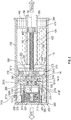
FIG. 2 shows a cross section of a piston assembly utilized for opening and closing the door illustrated inFIG. 1 , wherein a slider in the piston assembly is shown in one position; -
FIG. 3 shows a cross section of the piston assembly ofFIG. 2 , wherein a slider in the piston assembly is shown in another position; and -
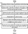
FIG. 4 is a flowchart showing a method of operating the piston assembly ofFIG. 2 . - A detailed description of one or more embodiments of the disclosed apparatus and method are presented herein by way of exemplification and not limitation with reference to the Figures.
-
FIG. 1 illustrates an example of acommercial aircraft 10 having aircraft engines surrounded by (or otherwise carried in) anacelle 20. Theaircraft 10 includes twowings 22 that can each include one ormore slats 24 and one ormore flaps 26. The aircraft may further includeailerons 27,spoilers 28, horizontalstabilizer trim tabs 29,horizontal stabilizer 30 andrudder 31, and vertical stabilizer 32 (the tail structure being collectively referred to as an and empennage) each of which may be typically referred to as "control surfaces" as they are movable under aircraft power systems. In addition, theaircraft 10 may include anaccess door 50 for accessing one or more internal systems. Theaccess door 50 may function on hydraulics, utilizing a hydraulically actuated piston, to deploy and retract thedoor 50. - As indicated, partial opening or closing of the door may be difficult. For example, if hydraulic fluid were to lose pressure, e.g., due to leakage of hydraulic fluid around warn piston seals, the piston may tend to fully retract the door despite there being an intention to partially open or close the door.
- Turning to
FIG. 2 , a piston assembly 100 is shown, which may be utilized for opening and closing of the access door 50 (or other door) of theaircraft 10. The piston assembly 100 may include apiston housing 110 that is substantially cylindrical. Apiston shaft 120 that is substantially cylindrical may be disposed within thepiston housing 110. Thepiston shaft 120 may be configured for translation in either forward or aft directions when fluid is respectively supplied to or removed from thepiston housing 110. That is, translation in the forward direction of thepiston shaft 120 deploys thepiston shaft 120 from thepiston housing 110. Translation in the aft direction of thepiston shaft 120 retracts thepiston shaft 120 into the housing. As can be appreciated, when thepiston shaft 120 is deployed, theaccess door 50 is opened. When thepiston shaft 120 is retracted, theaccess door 50 is closed. As illustrated, fluid may be supplied to and removed from a pistonhousing fluid port 1110 of thepiston housing 110. - A
screw shaft 130 that is substantially cylindrical is disposed within thepiston housing 110. Thescrew shaft 130 includes afirst gear 140. Thescrew shaft 130 is configured to rotate without translation in either the forward or aft directions when thepiston shaft 120 translates. That is, for thepiston shaft 120 to translate, thescrew shaft 130 has to rotate. This is becausepiston shaft 120 andscrew shaft 130 forms a screw-nut pair. Aslider 150 that is substantially cylindrical is disposed within thepiston housing 110. Theslider 150 andscrew shaft 130 are aligned with one another relative to a pistonhousing center axis 155 of thepiston housing 150. Theslider 150 includes asecond gear 160. Theslider 150 is configured for translation in either the forward or aft directions without rotation. For example, theslider 150 is configured to be in a first position (FIG. 2 ) while fluid is being supplied to and removed frompiston housing 110. Theslider 150 is configured to be in a second position (FIG. 3 ) when fluid is stalled in thepiston housing 110. In one embodiment thefirst gear 140 and thesecond gear 160 are dog gears that extend radially toward one another. In one embodiment thefirst gear 140 and thesecond gear 160 form a dog gear set. Dog gear sets have fewer and larger teeth which enable the dog gear to fully engage and disengage during rotation of one or both of the dog gear in the set. - As discussed in greater detail below, when the
slider 150 is in the first position (FIG. 2 ), thefirst gear 140 and thesecond gear 160 are spaced apart from one another along the pistonhousing center axis 155. When theslider 150 is in the second position (FIG. 3 ), thefirst gear 140 and thesecond gear 160 are aligned with one another relative to the pistonhousing center axis 155 and are thus capable of engaging with one another. As illustrated inFIG. 3 , thesecond gear 160 surrounds thefirst gear 140 whenfirst gear teeth 1410 of thefirst gear 140 andgear teeth 1610 of the second gear engage one another. Theslider 150 does not rotate. Thus, engagement of the first andsecond gears screw shaft 130. This prevents relative rotation between thescrew shaft 130 and thepiston shaft 120, which prevents translation in either the forward or aft directions of thepiston shaft 120. - As illustrated in
FIG. 2 , theslider 150 is disposed aft of thepiston shaft 120. Thescrew shaft 130 includes a screw shaftaft end 200. The screw shaftaft end 200 includes thefirst gear 140. In addition, theslider 150 includes a sliderforward end 210 and a slider aft end 220. The sliderforward end 210 includes thesecond gear 160. When theslider 150 is in the first position (FIG. 2 ), thegear teeth 1610 of thesecond gear 160 are forward of thegear teeth 1610 of thefirst gear 140. - The
slider 150 defines a sliderouter wall 205 that extends from the sliderforward end 210 to the slider aft end 220. Further, theslider 150 defines a sliderforward cavity 240. The sliderforward end 210 further defines a slider forward opening 250 that opens into the slider forwardcavity 240. The slider forward opening 250 may be formed by thesecond gear 160. When theslider 150 is in the first position (FIG. 2 ), thefirst gear teeth 1410 may be within the slider forwardcavity 240 such that theslider 150 and thefirst gear 140 are in a non-contact configuration with respect to one another. - The
piston housing 110 includes a piston housingaft end 260. Theslider 150 is forward of the piston housingaft end 260. A stub shaft 270 that is substantially cylindrical extends forward from the piston housing aft end 260 to engage theslider 150. The stub shaft 270 is also aligned with the pistonhousing center axis 155. Theslider 150 defines a slider aftcavity 275. The slider aft end 220 further defines a slider aft opening 280 that opens into the slider aftcavity 275. The slider aftcavity 275 is configured to receive the stub shaft 270 such that theslider 150 is configured for translating in either the forward or aft directions against the stub shaft 270. - The
slider 150 includes a slideraft end lip 1510 that faces radially inwardly. The stub shaft 270 includes a stub shaftforward end lip 2710 that is faces radially outwardly. The slideraft end lip 1510 and the stub shaftforward end lip 2710 engage one another to prevent theslider 150 from sliding off the stub shaft 270 and to limit a translational range of theslider 150 against the stub shaft 270. - The
slider 150 includes aslider divider wall 285 intermediate of the sliderforward end 210 and the slider aft end 220. Theslider divider wall 285 separates the slider forwardcavity 240 from the slider aftcavity 275. Theslider divider wall 285 defines a sliderfluid feed port 300 that fluidly connects the slider forwardcavity 240 and the slider aftcavity 275. - A
first biasing member 290 extends from the piston housing aft end 260 to engage theslider 150. Thefirst biasing member 290 may be disposed on an exterior side of the stub shaft 270 and engage the slider aft end 220. The stub shaft 270 may be hollow and define a stub shaftouter wall 305 and astub shaft cavity 310. Asecond biasing member 320 may be seated within thestub shaft cavity 310, against the piston housingaft end 260, and may extend from the piston housingaft end 260 toward theslider divider wall 285. According to an embodiment the first andsecond biasing members - According to an embodiment the first and
second biasing members slider 150 to the first position (FIG. 2 ). Pressure within the slider aftcavity 275 because of the openedslider fluid port 300, while supplying fluid to thepiston housing 110 generates a second biasing force F2, e.g., against an aft side of theslider divider wall 285. The second biasing force F2 also tends to bias the slider to the first position (FIG. 2 ). On the other hand, fluid pressure generates a third biasing force F3 against, e.g., a forward side of theslider divider wall 285 as well as a forward side of thesecond gear 160. The third biasing force tends to bias theslider 150 to the second position (FIG. 3 ). - According to an embodiment the
slider divider wall 285 defines a sliderfluid return port 330. Fluid flows out of the slider aftcavity 275 through the sliderfluid return port 330 while fluid flows into the slider aftcavity 275 through sliderfluid feed port 300. According to an embodiment the sliderfluid feed port 300 and sliderfluid return port 330 may respectively include first and second spring loadedstoppers port stopper 3010 in the sliderfluid feed port 300 may be configured to allow flow therethrough only when flow pressure is above a predetermined pressure, e.g., at least as great as fluid supply pressure when fluid is supplied into thepiston housing 110. - With the utilization of the first and second spring loaded
stoppers piston housing 110, e.g., for the purpose of generating translation in the forward direction of thepiston shaft 120. This occurs, e.g., when seeking to open thedoor 50. That is, the second biasing force F2 is not generated while fluid is removed from thepiston housing 110, for the purpose of generating translation in the aft direction of thepiston shaft 120. This occurs when seeking to close thedoor 50. In addition, the second biasing force F2 is not generated when fluid is stalled in thepiston housing 110, i.e., when fluid is neither being supplied to nor removed from thepiston shaft 120. This occurs, e.g., when seeking to maintain thedoor 50 in a partially opened or partially closed position. - Regarding the configuration of the
slider 150, and the first andsecond biasing members piston housing 110, the following applies to bias theslider 150 to the first position (FIG. 2 ):
F1+F2>F3(supply). - Here, F3 is the force generated during supply of fluid to the
piston housing 110 and deploying thepiston shaft 120 from thepiston housing 110 by translating thepiston shaft 120 in the forward direction. As indicated theslider 150 is biased to the first position (FIG. 2 ). This configuration spaces the first andsecond gears housing center axis 155. This enables rotation of thescrew shaft 130 and enables translation in the forward direction of thepiston shaft 120, which enables opening of thedoor 50. - In addition, the
slider 150, and the first andsecond biasing members piston housing 110, F2 is not generated, and the spring forces Flare greater than F3 to bias theslider 150 to the first position (FIG. 2 ).
F1>F3(return). - Here, F3(return) is the force generated when removing fluid from the
piston housing 110 and retracting (returning) thepiston shaft 120 into thepiston housing 110 by translating thepiston shaft 120 in the aft direction. As indicated theslider 150 is biased to the first position (FIG. 2 ). This configuration spaces the first andsecond gears housing center axis 155. This enables rotation of thescrew shaft 130, enabling translation in the aft direction of thepiston shaft 120. This enables closing of the access door 50 (FIG. 1 ). - Further, the
slider 150, and the first andsecond biasing members piston housing 110, i.e., when fluid is neither supplied to nor removed from thepiston housing 110, the spring forces F1 are less than the fluid biasing forces to bias theslider 150 to the second position (FIG. 3 ):
F1<F3(stall). - Here, F3(stall) is the force generated when pressure in the
piston housing 110 reaches the stall pressure for the fluid. As indicated theslider 150 is biased to the second position (FIG. 3 ). This enables engagement of the first andsecond gears screw shaft 130 and preventing translation of thepiston shaft 120. This locks the access door 50 (FIG. 1 ) in a partially opened or partially closed position. - According to an embodiment, the
slider 150 includes acavity cap 340 disposed at a forward end of the slider aftcavity 275. Thecavity cap 340 fluidly isolates thesecond biasing member 320 from fluid in the slider aftcavity 275. For example, thecavity cap 340 defines a cavity capouter wall 3410 that is cylindrically shaped and extends aft from a cavity capforward end 3420. Thesecond biasing member 320 engages the cavity capouter wall 3410 when biasing theslider 150 to the first position (FIG. 2 ). - A
gap cavity 345 is formed in a gap between the cavity capforward end 3420 and theslider divider wall 285. Thegap cavity 345 is located at a forward end of the slider aftcavity 275. Aft of theslider divider wall 285, fluid fills only thegap cavity 345 when fluid enters the slider aftcavity 275 through the sliderfluid feed port 300. This is sufficient to generate the second biasing force F2 against the aft side of theslider divider wall 285 that tends to bias theslider 150 to the first position (FIG. 2 ). - The cavity cap
outer wall 3410 is sized to form a skirt that slides against stub shaftouter wall 305 when theslider 150 translates between the first position (FIG. 2 ) and the second position (FIG. 3 ). An o-ring groove 3430 is formed in the cavity capouter wall 3410 for fitting an o-ring therein to provide a fluid seal that fluidly isolates thesecond biasing member 320 from fluid in thegap cavity 345. This arrangement ofcavity cap 340 restricts the fluid from retaining in thegap cavity 345 while the pressure inside the cylinder is changed from supply to stall. - The
piston housing 110 defines a piston housingouter wall 350. Thescrew shaft 130 includes a screw shaft aftdisk 360 connected to the screw shaftaft end 200. The screw shaft aftdisk 360 is aft of thepiston shaft 120. Anouter diameter 370 of the screw shaft aftdisk 360 is supported at the piston housingouter wall 350, e.g., by abearing 3510. With this configuration thescrew shaft 130 rotates without translation in either the forward or aft directions when thepiston shaft 120 translates. Thefirst gear 140 is connected to thescrew shaft 130 via an aft side of the screw shaft aftdisk 360. Further, as illustrated, the pistonhousing fluid port 1110 may be located in the piston housingouter wall 350, between the piston housingaft end 260 and thebearing 3510. - A piston shaft forward end 380 of the
piston shaft 120 extends through a piston housing forward end 390 of thepiston housing 110. A piston shaftaft end 400 of thepiston shaft 120 includes a piston shaft aftdisk 410 that defines a piston skirt which slides against the piston housingouter wall 350. The piston shaft aftdisk 410 is forward of the screw shaft aftdisk 360. - The
piston shaft 120 defines a piston shaftouter wall 420. The piston shaft aftdisk 410 defines ascrew shaft opening 430. Thescrew shaft 130 extends through thescrew shaft opening 430, into thepiston shaft 120. - A piston
housing end cap 440 is disposed at the piston housingforward end 390. The pistonhousing end cap 440 defines apiston shaft opening 450 through which thepiston shaft 120 extends. The pistonhousing end cap 440 forms a fluid seal between the piston housingouter wall 350 and the piston shaftouter wall 420. - A screw shaft forward
disk 460 is disposed at a screw shaft forward end 470 of thescrew shaft 130. The screw shaft forwarddisk 460 is sized to slide against the piston shaftouter wall 420 and form another fluid seal, i.e., against the piston shaftouter wall 420. - Turning to
FIG. 4 , a flowchart shows a method of operating the piston assembly 100. As shown inblock 510 the method includes supplying a fluid to, or removing fluid from, thepiston housing 110. As shown inblock 520 the method includes biasing theslider 150 in thepiston housing 110 in the first position (FIG. 2 ) from the fluid pressure generated when supplying the fluid to, or removing the fluid from, thepiston housing 110. In this position, thefirst gear 140 at the screw shaftaft end 200 of thescrew shaft 130 and thesecond gear 160 at the slider forward end 210 of theslider 150 are spaced apart from one another along the pistonhousing center axis 155. From this, thescrew shaft 130 is allowed to rotate. - As shown in
block 530 the method includes translating thepiston shaft 120 from pressure in thepiston housing 110 while thescrew shaft 130 is allowed to rotate. As indicated thepiston shaft 120 is translated in the forward direction in response to supply pressure in thepiston housing 110 and translated in the aft direction in response to return pressure in thepiston housing 110. - As shown in
block 540 the method includes stalling fluid within thepiston housing 110. As shown inblock 550 the method includes biasing theslider 150 in thepiston housing 110 in the second position (FIG. 3 ) from the fluid pressure while fluid is stalled in thepiston housing 110. In this position, thefirst gear 140 and thesecond gear 160 are configured to engage one another, and thescrew shaft 130 is prevented from rotating. As shown inblock 560 the method includes securing thepiston shaft 120 from translation by engagement with thescrew shaft 130 while thescrew shaft 130 is prevented from rotating. - The terminology used herein is for the purpose of describing particular embodiments only and is not intended to be limiting of the present disclosure. As used herein, the singular forms "a", "an" and "the" are intended to include the plural forms as well, unless the context clearly indicates otherwise. It will be further understood that the terms "comprises" and/or "comprising," when used in this specification, specify the presence of stated features, integers, steps, operations, elements, and/or components, but do not preclude the presence or addition of one or more other features, integers, steps, operations, element components, and/or groups thereof.
- Those of skill in the art will appreciate that various example embodiments are shown and described herein, each having certain features in the particular embodiments, but the present disclosure is not thus limited. Rather, the present disclosure can be modified to incorporate any number of variations, alterations, substitutions, combinations, sub-combinations, or equivalent arrangements not heretofore described, but which are commensurate with the scope of the present disclosure. Additionally, while various embodiments of the present disclosure have been described, it is to be understood that aspects of the present disclosure may include only some of the described embodiments. Accordingly, the present disclosure is not to be seen as limited by the foregoing description, but is only limited by the scope of the appended claims.
Claims (15)
- A piston assembly (100) for an aircraft, comprising:a piston housing (110);a piston housing fluid port formed in the piston housing for supplying fluid to and removing fluid from the piston housing;a piston shaft (120) disposed within the piston housing, wherein the piston shaft is configured for translation in either forward or aft directions when fluid is respectively supplied to or removed from the piston housing;a screw shaft (130) disposed within the piston housing, wherein the screw shaft includes a first gear (140) that rotates without translation in either the forward or aft directions while the piston shaft translates in either the forward or aft directions; anda slider (150) disposed within the piston housing, wherein the slider includes a second gear (160), and wherein the slider is configured for translation in either the forward or aft directions without rotation,wherein:
the slider (150) moves between a first position where the first gear (140) and the second gear (160) are separated from one another to allow the piston shaft to translate in the forward direction or the aft direction and a second position where the second gear surrounds the first gear so that the first and second gears are engaged with one another and the piston shaft is prevented from translating in the forward or aft directions. - The piston assembly of claim 1, wherein:the first gear (140) is located at a screw shaft aft end (200);the second gear (160) is located at the slider forward end (210); andthe slider and screw shaft are aligned with one another relative to a piston housing center axis (155).
- The piston assembly of claim 2, wherein:a slider outer wall (205) extends from the slider forward end to a slider aft end;the slider defines a slider forward cavity (240), wherein the slider forward end further defines a slider forward opening into the slider forward cavity; andthe slider forward cavity is configured to receive the first gear when the slider is in the first position.
- The piston assembly of claim 3, wherein:the slider (150) is forward of a piston housing aft end (260;a stub shaft (270) extends forward from the piston housing aft end to engage the slider, wherein the stub shaft is aligned with the piston housing center axis;the slider defines a slider aft cavity (275), wherein the slider aft end further defines a slider aft opening (280) that opens into the slider aft cavity; andthe slider aft cavity is configured to receive the stub shaft and the slider is configured for translating in either forward or aft directions against the stub shaft; and wherein:the slider includes a slider divider wall (285) intermediate the slider forward end and the slider aft end, wherein the slider divider wall separates the slider forward cavity from the slider aft cavity;the slider divider wall defines a slider fluid feed port that is configured to fluidly connect the slider forward cavity and the slider aft cavity; anda first biasing member (290) extends from the piston housing aft end to engage the slider.
- The piston assembly of claim 4, wherein:
the slider fluid feed port (300) includes a flow control valve that is configured for preventing flow under a predetermined pressure from flowing to the slider aft cavity. - The piston assembly of claim 5, wherein:the slider divider wall defines a slider fluid return port, andthe slider fluid return port (330) is configured to allow fluid to flow out of the slider aft cavity through the slider fluid return port while fluid flows into the slider aft cavity through the slider fluid feed port.
- The piston assembly of claim 6 or 7, wherein the first biasing member (290) is disposed on an exterior side of the stub shaft and engages the slider aft end.
- The piston assembly of claim 7, wherein:the stub shaft (270) defines a stub shaft cavity (310); anda second biasing member (320) is seated within the stub shaft cavity, against the piston housing aft end, and wherein the second biasing member extends from the piston housing aft end to engage the slider divider wall.
- The piston assembly of claim 8, wherein:the first biasing member and the second biasing member are springs; and/orwherein:the slider includes a cavity cap (340) disposed at a forward end of the slider aft cavity, andthe cavity cap is configured to fluidly isolate the second biasing member from fluid in the slider aft cavity.
- The piston assembly of claim 7, wherein:the piston housing defines a piston housing outer wall (350); andthe screw shaft includes a screw shaft aft disk (360),wherein:an outer diameter of the screw shaft aft disk is supported at the piston housing outer wall so that the screw shaft is configured to rotate without translation in either the forward or aft directions while the piston shaft translates; andthe first gear is connected to the screw shaft via an aft side of the screw shaft aft disk.
- The piston assembly of claim 10, wherein:
a bearing (3510) supports the screw shaft aft disk at the piston housing outer wall. - The piston assembly of claim 10 or 11, wherein:a piston shaft forward end (380) extends through a piston housing forward end; anda piston shaft aft end (400) includes a piston shaft aft disk (410) that defines a piston skirt which slides against the piston housing outer wall; and preferablywherein:the piston shaft defines a piston shaft outer wall (420);the piston shaft aft disk defines a screw shaft opening (430); andthe screw shaft extends through the screw shaft opening, into the piston shaft; and more preferablywherein:a piston housing end cap (440) is disposed at the piston housing forward end;the piston housing end cap defines a piston shaft opening through which the piston shaft extends; anda fluid seal is formed by the piston housing end cap, between the piston housing outer wall and the piston shaft outer wall; and more preferablywherein:a screw shaft forward disk (460) is disposed at a screw shaft forward end; andthe screw shaft forward disk is sized to slide against the piston shaft outer wall and form another fluid seal against the piston shaft outer wall.
- The piston assembly of claim 10, wherein:
the piston housing fluid port is defined in the piston housing outer wall between the screw shaft aft disk and the piston housing aft end. - An aircraft comprising:a door (50) connected to the aircraft and configured to pivot between an opened position and a closed position; andthe piston assembly (100) of any preceding claim connected to the door and to the aircraft.
- A method of actuating a piston, comprising:supplying fluid to or removing fluid from a piston housing;biasing a slider in the piston housing in a first position from pressure in the piston housing, whereby a first gear at a screw shaft aft end of a screw shaft and a second gear at a slider forward end of the slider are spaced apart from one another, and the screw shaft is allowed to rotate;translating a piston shaft from fluid pressure in the piston housing while the screw shaft is allowed to rotate, wherein the piston shaft is translated in a forward direction in response to supply pressure in the piston housing and translated in an art direction in response to return pressure in the piston housing;stalling fluid within the piston housing;biasing the slider in the piston housing in a second position from pressure in the piston housing, whereby the first gear and the second gear engage one another, and the screw shaft is prevented from rotating; andsecuring the piston shaft from translation by engagement with the screw shaft while the screw shaft is in the second position.
Applications Claiming Priority (1)
| Application Number | Priority Date | Filing Date | Title |
|---|---|---|---|
| IN201911054243 | 2019-12-27 |
Publications (2)
| Publication Number | Publication Date |
|---|---|
| EP3842334A1 true EP3842334A1 (en) | 2021-06-30 |
| EP3842334B1 EP3842334B1 (en) | 2024-07-10 |
Family
ID=73543123
Family Applications (1)
| Application Number | Title | Priority Date | Filing Date |
|---|---|---|---|
| EP20208921.5A Active EP3842334B1 (en) | 2019-12-27 | 2020-11-20 | Piston assembly for aircraft door |
Country Status (2)
| Country | Link |
|---|---|
| US (1) | US11187023B2 (en) |
| EP (1) | EP3842334B1 (en) |
Citations (5)
| Publication number | Priority date | Publication date | Assignee | Title |
|---|---|---|---|---|
| US3763747A (en) * | 1971-06-28 | 1973-10-09 | Aerojet General Co | Fluid-operable linear actuators |
| US4932311A (en) * | 1987-12-29 | 1990-06-12 | Daihatsu Diesel Mfg. Co., Ltd. | Fluid apparatus |
| EP0469253A1 (en) * | 1990-07-30 | 1992-02-05 | UNIVER S.p.A. | Fluid-operated, programmable, linear actuator |
| DE4141460A1 (en) * | 1991-12-12 | 1993-06-17 | Mannesmann Ag | Pressure driven ram with piston and tubular piston rod - has sliding screw-bush placed axially beside ball-screw-bush, connected together by clutch pins |
| US20190315450A1 (en) * | 2018-04-13 | 2019-10-17 | The Boeing Company | Base Flight Control Member Orientation Mechanism And Control |
Family Cites Families (12)
| Publication number | Priority date | Publication date | Assignee | Title |
|---|---|---|---|---|
| US2705939A (en) | 1952-07-01 | 1955-04-12 | Gen Motors Corp | Fluid pressure actuator |
| US2801615A (en) | 1954-02-19 | 1957-08-06 | Gen Motors Corp | Actuator with multiple disc type locking means |
| GB2429503B (en) | 2005-08-24 | 2008-07-23 | Engineering Dynamics | Screw-threaded fastening devices |
| JP4890845B2 (en) * | 2005-12-08 | 2012-03-07 | ナブテスコ株式会社 | Actuator mechanism |
| US10107347B2 (en) * | 2016-05-19 | 2018-10-23 | The Boeing Company | Dual rack and pinion rotational inerter system and method for damping movement of a flight control surface of an aircraft |
| US10088006B2 (en) * | 2016-05-19 | 2018-10-02 | The Boeing Company | Rotational inerter and method for damping an actuator |
| EP3458725A4 (en) * | 2016-05-19 | 2020-02-19 | Saab Ab | An aircraft secondary control system for aircraft and a method for operating the system |
| US10145434B2 (en) * | 2016-05-19 | 2018-12-04 | The Boeing Company | Translational inerter assembly and method for damping movement of a flight control surface |
| FR3054199B1 (en) * | 2016-07-25 | 2019-08-02 | Airbus Operations | SYSTEM FOR ACTUATING A CONTROL SURFACE OF AN AIRCRAFT. |
| US10829203B2 (en) * | 2018-04-06 | 2020-11-10 | The Boeing Company | Distributed trailing edge wing flap systems |
| US10793261B2 (en) * | 2018-04-13 | 2020-10-06 | The Boeing Company | Electro-mechanically biased supercritical flight control surface loading to reduce high pressure actuation cycles |
| US11027824B2 (en) * | 2018-09-05 | 2021-06-08 | The Boeing Company | Distributed trailing edge wing flap systems |
-
2020
- 2020-02-21 US US16/797,486 patent/US11187023B2/en active Active
- 2020-11-20 EP EP20208921.5A patent/EP3842334B1/en active Active
Patent Citations (5)
| Publication number | Priority date | Publication date | Assignee | Title |
|---|---|---|---|---|
| US3763747A (en) * | 1971-06-28 | 1973-10-09 | Aerojet General Co | Fluid-operable linear actuators |
| US4932311A (en) * | 1987-12-29 | 1990-06-12 | Daihatsu Diesel Mfg. Co., Ltd. | Fluid apparatus |
| EP0469253A1 (en) * | 1990-07-30 | 1992-02-05 | UNIVER S.p.A. | Fluid-operated, programmable, linear actuator |
| DE4141460A1 (en) * | 1991-12-12 | 1993-06-17 | Mannesmann Ag | Pressure driven ram with piston and tubular piston rod - has sliding screw-bush placed axially beside ball-screw-bush, connected together by clutch pins |
| US20190315450A1 (en) * | 2018-04-13 | 2019-10-17 | The Boeing Company | Base Flight Control Member Orientation Mechanism And Control |
Also Published As
| Publication number | Publication date |
|---|---|
| US20210198932A1 (en) | 2021-07-01 |
| EP3842334B1 (en) | 2024-07-10 |
| US11187023B2 (en) | 2021-11-30 |
Similar Documents
| Publication | Publication Date | Title |
|---|---|---|
| US9969233B2 (en) | Mechanical actuator with a hydraulic damper device | |
| EP3290332B1 (en) | Propeller pitch control actuation system | |
| DE112015001050B4 (en) | Rotary actuator with integrated actuation | |
| EP2945841B1 (en) | Master cylinder device for a hydraulic disk brake | |
| CN106364661A (en) | Actuator | |
| EP2365193A1 (en) | Camshaft phase adjuster with control valve for hydraulic adjustment of the phasing of a camshaft | |
| EP2960437A1 (en) | Variable guide vane device for a gas turbine and gas turbine equipped with such a device | |
| DE112020001458T5 (en) | Hydraulic oil control valve and valve timing adjustment device | |
| CN104612855A (en) | Fan nozzle drive systems that lock thrust reversers | |
| EP4172460B1 (en) | Actuator and associated methods | |
| DE112007002323T5 (en) | Variable turbocharger and method of driving the same | |
| DE112020001449T5 (en) | Hydraulic oil control valve and valve timing adjustment device | |
| CN103523206B (en) | A hydraulic control valve, a device for adjusting blade pitch, and an aircraft provided with the valve | |
| US20080048140A1 (en) | Fluid saving blowout preventer operator system | |
| US11187023B2 (en) | Piston assembly for aircraft door | |
| EP1825106B1 (en) | Control valve | |
| DE102014218299B4 (en) | Camshaft adjuster with central valve and without T-outlet | |
| US10100848B2 (en) | Hydraulic actuator and method of producing the same | |
| EP4001103B1 (en) | Actuator | |
| EP3015662B1 (en) | Hydraulic valve and a tilt motor adjuster | |
| SG191489A1 (en) | Power assisted manual valve system | |
| DE102014220727A1 (en) | Camshaft adjuster with central valve and check valves | |
| DE102012211108A1 (en) | Camshaft adjusting device for an internal combustion engine | |
| DE102017102842A1 (en) | Shaft passage and valve with such a shaft passage and method for producing a shaft passage | |
| DE102012208808A1 (en) | Control valve for controlling pressure medium flow of camshaft adjusting device, has radial bores which are spaced apart from each other in control sleeve and formed with greater diameter than the width of inner annular groove |
Legal Events
| Date | Code | Title | Description |
|---|---|---|---|
| PUAI | Public reference made under article 153(3) epc to a published international application that has entered the european phase |
Free format text: ORIGINAL CODE: 0009012 |
|
| STAA | Information on the status of an ep patent application or granted ep patent |
Free format text: STATUS: THE APPLICATION HAS BEEN PUBLISHED |
|
| AK | Designated contracting states |
Kind code of ref document: A1 Designated state(s): AL AT BE BG CH CY CZ DE DK EE ES FI FR GB GR HR HU IE IS IT LI LT LU LV MC MK MT NL NO PL PT RO RS SE SI SK SM TR |
|
| STAA | Information on the status of an ep patent application or granted ep patent |
Free format text: STATUS: REQUEST FOR EXAMINATION WAS MADE |
|
| 17P | Request for examination filed |
Effective date: 20211223 |
|
| RBV | Designated contracting states (corrected) |
Designated state(s): AL AT BE BG CH CY CZ DE DK EE ES FI FR GB GR HR HU IE IS IT LI LT LU LV MC MK MT NL NO PL PT RO RS SE SI SK SM TR |
|
| STAA | Information on the status of an ep patent application or granted ep patent |
Free format text: STATUS: EXAMINATION IS IN PROGRESS |
|
| 17Q | First examination report despatched |
Effective date: 20221214 |
|
| GRAP | Despatch of communication of intention to grant a patent |
Free format text: ORIGINAL CODE: EPIDOSNIGR1 |
|
| STAA | Information on the status of an ep patent application or granted ep patent |
Free format text: STATUS: GRANT OF PATENT IS INTENDED |
|
| INTG | Intention to grant announced |
Effective date: 20240209 |
|
| GRAS | Grant fee paid |
Free format text: ORIGINAL CODE: EPIDOSNIGR3 |
|
| GRAA | (expected) grant |
Free format text: ORIGINAL CODE: 0009210 |
|
| STAA | Information on the status of an ep patent application or granted ep patent |
Free format text: STATUS: THE PATENT HAS BEEN GRANTED |
|
| AK | Designated contracting states |
Kind code of ref document: B1 Designated state(s): AL AT BE BG CH CY CZ DE DK EE ES FI FR GB GR HR HU IE IS IT LI LT LU LV MC MK MT NL NO PL PT RO RS SE SI SK SM TR |
|
| REG | Reference to a national code |
Ref country code: CH Ref legal event code: EP |
|
| REG | Reference to a national code |
Ref country code: DE Ref legal event code: R096 Ref document number: 602020033670 Country of ref document: DE |
|
| REG | Reference to a national code |
Ref country code: LT Ref legal event code: MG9D |
|
| REG | Reference to a national code |
Ref country code: NL Ref legal event code: MP Effective date: 20240710 |
|
| PG25 | Lapsed in a contracting state [announced via postgrant information from national office to epo] |
Ref country code: PT Free format text: LAPSE BECAUSE OF FAILURE TO SUBMIT A TRANSLATION OF THE DESCRIPTION OR TO PAY THE FEE WITHIN THE PRESCRIBED TIME-LIMIT Effective date: 20241111 |
|
| REG | Reference to a national code |
Ref country code: AT Ref legal event code: MK05 Ref document number: 1701844 Country of ref document: AT Kind code of ref document: T Effective date: 20240710 |
|
| PG25 | Lapsed in a contracting state [announced via postgrant information from national office to epo] |
Ref country code: NL Free format text: LAPSE BECAUSE OF FAILURE TO SUBMIT A TRANSLATION OF THE DESCRIPTION OR TO PAY THE FEE WITHIN THE PRESCRIBED TIME-LIMIT Effective date: 20240710 |
|
| PG25 | Lapsed in a contracting state [announced via postgrant information from national office to epo] |
Ref country code: PT Free format text: LAPSE BECAUSE OF FAILURE TO SUBMIT A TRANSLATION OF THE DESCRIPTION OR TO PAY THE FEE WITHIN THE PRESCRIBED TIME-LIMIT Effective date: 20241111 Ref country code: NL Free format text: LAPSE BECAUSE OF FAILURE TO SUBMIT A TRANSLATION OF THE DESCRIPTION OR TO PAY THE FEE WITHIN THE PRESCRIBED TIME-LIMIT Effective date: 20240710 |
|
| PG25 | Lapsed in a contracting state [announced via postgrant information from national office to epo] |
Ref country code: NO Free format text: LAPSE BECAUSE OF FAILURE TO SUBMIT A TRANSLATION OF THE DESCRIPTION OR TO PAY THE FEE WITHIN THE PRESCRIBED TIME-LIMIT Effective date: 20241010 |
|
| PG25 | Lapsed in a contracting state [announced via postgrant information from national office to epo] |
Ref country code: FI Free format text: LAPSE BECAUSE OF FAILURE TO SUBMIT A TRANSLATION OF THE DESCRIPTION OR TO PAY THE FEE WITHIN THE PRESCRIBED TIME-LIMIT Effective date: 20240710 Ref country code: GR Free format text: LAPSE BECAUSE OF FAILURE TO SUBMIT A TRANSLATION OF THE DESCRIPTION OR TO PAY THE FEE WITHIN THE PRESCRIBED TIME-LIMIT Effective date: 20241011 Ref country code: PL Free format text: LAPSE BECAUSE OF FAILURE TO SUBMIT A TRANSLATION OF THE DESCRIPTION OR TO PAY THE FEE WITHIN THE PRESCRIBED TIME-LIMIT Effective date: 20240710 |
|
| PG25 | Lapsed in a contracting state [announced via postgrant information from national office to epo] |
Ref country code: BG Free format text: LAPSE BECAUSE OF FAILURE TO SUBMIT A TRANSLATION OF THE DESCRIPTION OR TO PAY THE FEE WITHIN THE PRESCRIBED TIME-LIMIT Effective date: 20240710 |
|
| PG25 | Lapsed in a contracting state [announced via postgrant information from national office to epo] |
Ref country code: LV Free format text: LAPSE BECAUSE OF FAILURE TO SUBMIT A TRANSLATION OF THE DESCRIPTION OR TO PAY THE FEE WITHIN THE PRESCRIBED TIME-LIMIT Effective date: 20240710 |
|
| PG25 | Lapsed in a contracting state [announced via postgrant information from national office to epo] |
Ref country code: AT Free format text: LAPSE BECAUSE OF FAILURE TO SUBMIT A TRANSLATION OF THE DESCRIPTION OR TO PAY THE FEE WITHIN THE PRESCRIBED TIME-LIMIT Effective date: 20240710 Ref country code: IS Free format text: LAPSE BECAUSE OF FAILURE TO SUBMIT A TRANSLATION OF THE DESCRIPTION OR TO PAY THE FEE WITHIN THE PRESCRIBED TIME-LIMIT Effective date: 20241110 |
|
| PG25 | Lapsed in a contracting state [announced via postgrant information from national office to epo] |
Ref country code: HR Free format text: LAPSE BECAUSE OF FAILURE TO SUBMIT A TRANSLATION OF THE DESCRIPTION OR TO PAY THE FEE WITHIN THE PRESCRIBED TIME-LIMIT Effective date: 20240710 |
|
| PG25 | Lapsed in a contracting state [announced via postgrant information from national office to epo] |
Ref country code: ES Free format text: LAPSE BECAUSE OF FAILURE TO SUBMIT A TRANSLATION OF THE DESCRIPTION OR TO PAY THE FEE WITHIN THE PRESCRIBED TIME-LIMIT Effective date: 20240710 Ref country code: RS Free format text: LAPSE BECAUSE OF FAILURE TO SUBMIT A TRANSLATION OF THE DESCRIPTION OR TO PAY THE FEE WITHIN THE PRESCRIBED TIME-LIMIT Effective date: 20241010 |
|
| PG25 | Lapsed in a contracting state [announced via postgrant information from national office to epo] |
Ref country code: RS Free format text: LAPSE BECAUSE OF FAILURE TO SUBMIT A TRANSLATION OF THE DESCRIPTION OR TO PAY THE FEE WITHIN THE PRESCRIBED TIME-LIMIT Effective date: 20241010 Ref country code: PL Free format text: LAPSE BECAUSE OF FAILURE TO SUBMIT A TRANSLATION OF THE DESCRIPTION OR TO PAY THE FEE WITHIN THE PRESCRIBED TIME-LIMIT Effective date: 20240710 Ref country code: NO Free format text: LAPSE BECAUSE OF FAILURE TO SUBMIT A TRANSLATION OF THE DESCRIPTION OR TO PAY THE FEE WITHIN THE PRESCRIBED TIME-LIMIT Effective date: 20241010 Ref country code: LV Free format text: LAPSE BECAUSE OF FAILURE TO SUBMIT A TRANSLATION OF THE DESCRIPTION OR TO PAY THE FEE WITHIN THE PRESCRIBED TIME-LIMIT Effective date: 20240710 Ref country code: IS Free format text: LAPSE BECAUSE OF FAILURE TO SUBMIT A TRANSLATION OF THE DESCRIPTION OR TO PAY THE FEE WITHIN THE PRESCRIBED TIME-LIMIT Effective date: 20241110 Ref country code: HR Free format text: LAPSE BECAUSE OF FAILURE TO SUBMIT A TRANSLATION OF THE DESCRIPTION OR TO PAY THE FEE WITHIN THE PRESCRIBED TIME-LIMIT Effective date: 20240710 Ref country code: GR Free format text: LAPSE BECAUSE OF FAILURE TO SUBMIT A TRANSLATION OF THE DESCRIPTION OR TO PAY THE FEE WITHIN THE PRESCRIBED TIME-LIMIT Effective date: 20241011 Ref country code: FI Free format text: LAPSE BECAUSE OF FAILURE TO SUBMIT A TRANSLATION OF THE DESCRIPTION OR TO PAY THE FEE WITHIN THE PRESCRIBED TIME-LIMIT Effective date: 20240710 Ref country code: ES Free format text: LAPSE BECAUSE OF FAILURE TO SUBMIT A TRANSLATION OF THE DESCRIPTION OR TO PAY THE FEE WITHIN THE PRESCRIBED TIME-LIMIT Effective date: 20240710 Ref country code: BG Free format text: LAPSE BECAUSE OF FAILURE TO SUBMIT A TRANSLATION OF THE DESCRIPTION OR TO PAY THE FEE WITHIN THE PRESCRIBED TIME-LIMIT Effective date: 20240710 Ref country code: AT Free format text: LAPSE BECAUSE OF FAILURE TO SUBMIT A TRANSLATION OF THE DESCRIPTION OR TO PAY THE FEE WITHIN THE PRESCRIBED TIME-LIMIT Effective date: 20240710 |
|
| REG | Reference to a national code |
Ref country code: DE Ref legal event code: R097 Ref document number: 602020033670 Country of ref document: DE |
|
| PG25 | Lapsed in a contracting state [announced via postgrant information from national office to epo] |
Ref country code: SM Free format text: LAPSE BECAUSE OF FAILURE TO SUBMIT A TRANSLATION OF THE DESCRIPTION OR TO PAY THE FEE WITHIN THE PRESCRIBED TIME-LIMIT Effective date: 20240710 Ref country code: DK Free format text: LAPSE BECAUSE OF FAILURE TO SUBMIT A TRANSLATION OF THE DESCRIPTION OR TO PAY THE FEE WITHIN THE PRESCRIBED TIME-LIMIT Effective date: 20240710 Ref country code: RO Free format text: LAPSE BECAUSE OF FAILURE TO SUBMIT A TRANSLATION OF THE DESCRIPTION OR TO PAY THE FEE WITHIN THE PRESCRIBED TIME-LIMIT Effective date: 20240710 |
|
| PG25 | Lapsed in a contracting state [announced via postgrant information from national office to epo] |
Ref country code: EE Free format text: LAPSE BECAUSE OF FAILURE TO SUBMIT A TRANSLATION OF THE DESCRIPTION OR TO PAY THE FEE WITHIN THE PRESCRIBED TIME-LIMIT Effective date: 20240710 |
|
| PG25 | Lapsed in a contracting state [announced via postgrant information from national office to epo] |
Ref country code: CZ Free format text: LAPSE BECAUSE OF FAILURE TO SUBMIT A TRANSLATION OF THE DESCRIPTION OR TO PAY THE FEE WITHIN THE PRESCRIBED TIME-LIMIT Effective date: 20240710 |
|
| PG25 | Lapsed in a contracting state [announced via postgrant information from national office to epo] |
Ref country code: IT Free format text: LAPSE BECAUSE OF FAILURE TO SUBMIT A TRANSLATION OF THE DESCRIPTION OR TO PAY THE FEE WITHIN THE PRESCRIBED TIME-LIMIT Effective date: 20240710 Ref country code: SK Free format text: LAPSE BECAUSE OF FAILURE TO SUBMIT A TRANSLATION OF THE DESCRIPTION OR TO PAY THE FEE WITHIN THE PRESCRIBED TIME-LIMIT Effective date: 20240710 |
|
| PLBE | No opposition filed within time limit |
Free format text: ORIGINAL CODE: 0009261 |
|
| STAA | Information on the status of an ep patent application or granted ep patent |
Free format text: STATUS: NO OPPOSITION FILED WITHIN TIME LIMIT |
|
| 26N | No opposition filed |
Effective date: 20250411 |
|
| REG | Reference to a national code |
Ref country code: CH Ref legal event code: PL |
|
| PG25 | Lapsed in a contracting state [announced via postgrant information from national office to epo] |
Ref country code: MC Free format text: LAPSE BECAUSE OF FAILURE TO SUBMIT A TRANSLATION OF THE DESCRIPTION OR TO PAY THE FEE WITHIN THE PRESCRIBED TIME-LIMIT Effective date: 20240710 |
|
| PG25 | Lapsed in a contracting state [announced via postgrant information from national office to epo] |
Ref country code: LU Free format text: LAPSE BECAUSE OF NON-PAYMENT OF DUE FEES Effective date: 20241120 |
|
| REG | Reference to a national code |
Ref country code: CH Ref legal event code: PL |
|
| PG25 | Lapsed in a contracting state [announced via postgrant information from national office to epo] |
Ref country code: CH Free format text: LAPSE BECAUSE OF NON-PAYMENT OF DUE FEES Effective date: 20241130 |
|
| REG | Reference to a national code |
Ref country code: BE Ref legal event code: MM Effective date: 20241130 |
|
| PG25 | Lapsed in a contracting state [announced via postgrant information from national office to epo] |
Ref country code: SE Free format text: LAPSE BECAUSE OF FAILURE TO SUBMIT A TRANSLATION OF THE DESCRIPTION OR TO PAY THE FEE WITHIN THE PRESCRIBED TIME-LIMIT Effective date: 20240710 |
|
| PG25 | Lapsed in a contracting state [announced via postgrant information from national office to epo] |
Ref country code: BE Free format text: LAPSE BECAUSE OF NON-PAYMENT OF DUE FEES Effective date: 20241130 |
|
| PG25 | Lapsed in a contracting state [announced via postgrant information from national office to epo] |
Ref country code: IE Free format text: LAPSE BECAUSE OF NON-PAYMENT OF DUE FEES Effective date: 20241120 |
|
| PGFP | Annual fee paid to national office [announced via postgrant information from national office to epo] |
Ref country code: DE Payment date: 20251117 Year of fee payment: 6 |
|
| PGFP | Annual fee paid to national office [announced via postgrant information from national office to epo] |
Ref country code: GB Payment date: 20251126 Year of fee payment: 6 |
|
| PGFP | Annual fee paid to national office [announced via postgrant information from national office to epo] |
Ref country code: FR Payment date: 20251128 Year of fee payment: 6 |
|
| PG25 | Lapsed in a contracting state [announced via postgrant information from national office to epo] |
Ref country code: HU Free format text: LAPSE BECAUSE OF FAILURE TO SUBMIT A TRANSLATION OF THE DESCRIPTION OR TO PAY THE FEE WITHIN THE PRESCRIBED TIME-LIMIT; INVALID AB INITIO Effective date: 20201120 |
|
| PG25 | Lapsed in a contracting state [announced via postgrant information from national office to epo] |
Ref country code: CY Free format text: LAPSE BECAUSE OF FAILURE TO SUBMIT A TRANSLATION OF THE DESCRIPTION OR TO PAY THE FEE WITHIN THE PRESCRIBED TIME-LIMIT; INVALID AB INITIO Effective date: 20201120 |