EP3842283A1 - Battery charging system and battery charging method - Google Patents
Battery charging system and battery charging method Download PDFInfo
- Publication number
- EP3842283A1 EP3842283A1 EP19910649.3A EP19910649A EP3842283A1 EP 3842283 A1 EP3842283 A1 EP 3842283A1 EP 19910649 A EP19910649 A EP 19910649A EP 3842283 A1 EP3842283 A1 EP 3842283A1
- Authority
- EP
- European Patent Office
- Prior art keywords
- battery
- voltage
- switch
- coil
- state
- Prior art date
- Legal status (The legal status is an assumption and is not a legal conclusion. Google has not performed a legal analysis and makes no representation as to the accuracy of the status listed.)
- Pending
Links
Images


Classifications
-
- B—PERFORMING OPERATIONS; TRANSPORTING
- B60—VEHICLES IN GENERAL
- B60L—PROPULSION OF ELECTRICALLY-PROPELLED VEHICLES; SUPPLYING ELECTRIC POWER FOR AUXILIARY EQUIPMENT OF ELECTRICALLY-PROPELLED VEHICLES; ELECTRODYNAMIC BRAKE SYSTEMS FOR VEHICLES IN GENERAL; MAGNETIC SUSPENSION OR LEVITATION FOR VEHICLES; MONITORING OPERATING VARIABLES OF ELECTRICALLY-PROPELLED VEHICLES; ELECTRIC SAFETY DEVICES FOR ELECTRICALLY-PROPELLED VEHICLES
- B60L53/00—Methods of charging batteries, specially adapted for electric vehicles; Charging stations or on-board charging equipment therefor; Exchange of energy storage elements in electric vehicles
- B60L53/10—Methods of charging batteries, specially adapted for electric vehicles; Charging stations or on-board charging equipment therefor; Exchange of energy storage elements in electric vehicles characterised by the energy transfer between the charging station and the vehicle
- B60L53/12—Inductive energy transfer
- B60L53/122—Circuits or methods for driving the primary coil, e.g. supplying electric power to the coil
-
- B—PERFORMING OPERATIONS; TRANSPORTING
- B60—VEHICLES IN GENERAL
- B60L—PROPULSION OF ELECTRICALLY-PROPELLED VEHICLES; SUPPLYING ELECTRIC POWER FOR AUXILIARY EQUIPMENT OF ELECTRICALLY-PROPELLED VEHICLES; ELECTRODYNAMIC BRAKE SYSTEMS FOR VEHICLES IN GENERAL; MAGNETIC SUSPENSION OR LEVITATION FOR VEHICLES; MONITORING OPERATING VARIABLES OF ELECTRICALLY-PROPELLED VEHICLES; ELECTRIC SAFETY DEVICES FOR ELECTRICALLY-PROPELLED VEHICLES
- B60L53/00—Methods of charging batteries, specially adapted for electric vehicles; Charging stations or on-board charging equipment therefor; Exchange of energy storage elements in electric vehicles
- B60L53/10—Methods of charging batteries, specially adapted for electric vehicles; Charging stations or on-board charging equipment therefor; Exchange of energy storage elements in electric vehicles characterised by the energy transfer between the charging station and the vehicle
- B60L53/12—Inductive energy transfer
-
- B—PERFORMING OPERATIONS; TRANSPORTING
- B60—VEHICLES IN GENERAL
- B60L—PROPULSION OF ELECTRICALLY-PROPELLED VEHICLES; SUPPLYING ELECTRIC POWER FOR AUXILIARY EQUIPMENT OF ELECTRICALLY-PROPELLED VEHICLES; ELECTRODYNAMIC BRAKE SYSTEMS FOR VEHICLES IN GENERAL; MAGNETIC SUSPENSION OR LEVITATION FOR VEHICLES; MONITORING OPERATING VARIABLES OF ELECTRICALLY-PROPELLED VEHICLES; ELECTRIC SAFETY DEVICES FOR ELECTRICALLY-PROPELLED VEHICLES
- B60L53/00—Methods of charging batteries, specially adapted for electric vehicles; Charging stations or on-board charging equipment therefor; Exchange of energy storage elements in electric vehicles
- B60L53/30—Constructional details of charging stations
- B60L53/34—Plug-like or socket-like devices specially adapted for contactless inductive charging of electric vehicles
-
- B—PERFORMING OPERATIONS; TRANSPORTING
- B60—VEHICLES IN GENERAL
- B60L—PROPULSION OF ELECTRICALLY-PROPELLED VEHICLES; SUPPLYING ELECTRIC POWER FOR AUXILIARY EQUIPMENT OF ELECTRICALLY-PROPELLED VEHICLES; ELECTRODYNAMIC BRAKE SYSTEMS FOR VEHICLES IN GENERAL; MAGNETIC SUSPENSION OR LEVITATION FOR VEHICLES; MONITORING OPERATING VARIABLES OF ELECTRICALLY-PROPELLED VEHICLES; ELECTRIC SAFETY DEVICES FOR ELECTRICALLY-PROPELLED VEHICLES
- B60L58/00—Methods or circuit arrangements for monitoring or controlling batteries or fuel cells, specially adapted for electric vehicles
- B60L58/10—Methods or circuit arrangements for monitoring or controlling batteries or fuel cells, specially adapted for electric vehicles for monitoring or controlling batteries
-
- B—PERFORMING OPERATIONS; TRANSPORTING
- B60—VEHICLES IN GENERAL
- B60L—PROPULSION OF ELECTRICALLY-PROPELLED VEHICLES; SUPPLYING ELECTRIC POWER FOR AUXILIARY EQUIPMENT OF ELECTRICALLY-PROPELLED VEHICLES; ELECTRODYNAMIC BRAKE SYSTEMS FOR VEHICLES IN GENERAL; MAGNETIC SUSPENSION OR LEVITATION FOR VEHICLES; MONITORING OPERATING VARIABLES OF ELECTRICALLY-PROPELLED VEHICLES; ELECTRIC SAFETY DEVICES FOR ELECTRICALLY-PROPELLED VEHICLES
- B60L58/00—Methods or circuit arrangements for monitoring or controlling batteries or fuel cells, specially adapted for electric vehicles
- B60L58/10—Methods or circuit arrangements for monitoring or controlling batteries or fuel cells, specially adapted for electric vehicles for monitoring or controlling batteries
- B60L58/18—Methods or circuit arrangements for monitoring or controlling batteries or fuel cells, specially adapted for electric vehicles for monitoring or controlling batteries of two or more battery modules
-
- B—PERFORMING OPERATIONS; TRANSPORTING
- B60—VEHICLES IN GENERAL
- B60L—PROPULSION OF ELECTRICALLY-PROPELLED VEHICLES; SUPPLYING ELECTRIC POWER FOR AUXILIARY EQUIPMENT OF ELECTRICALLY-PROPELLED VEHICLES; ELECTRODYNAMIC BRAKE SYSTEMS FOR VEHICLES IN GENERAL; MAGNETIC SUSPENSION OR LEVITATION FOR VEHICLES; MONITORING OPERATING VARIABLES OF ELECTRICALLY-PROPELLED VEHICLES; ELECTRIC SAFETY DEVICES FOR ELECTRICALLY-PROPELLED VEHICLES
- B60L58/00—Methods or circuit arrangements for monitoring or controlling batteries or fuel cells, specially adapted for electric vehicles
- B60L58/10—Methods or circuit arrangements for monitoring or controlling batteries or fuel cells, specially adapted for electric vehicles for monitoring or controlling batteries
- B60L58/18—Methods or circuit arrangements for monitoring or controlling batteries or fuel cells, specially adapted for electric vehicles for monitoring or controlling batteries of two or more battery modules
- B60L58/22—Balancing the charge of battery modules
-
- H—ELECTRICITY
- H02—GENERATION; CONVERSION OR DISTRIBUTION OF ELECTRIC POWER
- H02J—ELECTRIC POWER NETWORKS; CIRCUIT ARRANGEMENTS OR SYSTEMS FOR SUPPLYING OR DISTRIBUTING ELECTRIC POWER; SYSTEMS FOR STORING ELECTRIC ENERGY
- H02J50/00—Circuit arrangements or systems for wireless supply or distribution of electric power
- H02J50/10—Circuit arrangements or systems for wireless supply or distribution of electric power using inductive coupling
-
- H—ELECTRICITY
- H02—GENERATION; CONVERSION OR DISTRIBUTION OF ELECTRIC POWER
- H02J—ELECTRIC POWER NETWORKS; CIRCUIT ARRANGEMENTS OR SYSTEMS FOR SUPPLYING OR DISTRIBUTING ELECTRIC POWER; SYSTEMS FOR STORING ELECTRIC ENERGY
- H02J7/00—Circuit arrangements for charging or discharging batteries or for supplying loads from batteries
- H02J7/40—Circuit arrangements for charging or discharging batteries or for supplying loads from batteries characterised by the exchange of charge or discharge related data
- H02J7/47—Arrangements for checking compatibility or authentication between one component, e.g. a battery or a battery charger, and another component, e.g. a power source
-
- H—ELECTRICITY
- H02—GENERATION; CONVERSION OR DISTRIBUTION OF ELECTRIC POWER
- H02J—ELECTRIC POWER NETWORKS; CIRCUIT ARRANGEMENTS OR SYSTEMS FOR SUPPLYING OR DISTRIBUTING ELECTRIC POWER; SYSTEMS FOR STORING ELECTRIC ENERGY
- H02J7/00—Circuit arrangements for charging or discharging batteries or for supplying loads from batteries
- H02J7/50—Circuit arrangements for charging or discharging batteries or for supplying loads from batteries acting upon multiple batteries simultaneously or sequentially
- H02J7/52—Circuit arrangements for charging or discharging batteries or for supplying loads from batteries acting upon multiple batteries simultaneously or sequentially for charge balancing, e.g. equalisation of charge between batteries
- H02J7/56—Active balancing, e.g. using capacitor-based, inductor-based or DC-DC converters
-
- H—ELECTRICITY
- H02—GENERATION; CONVERSION OR DISTRIBUTION OF ELECTRIC POWER
- H02J—ELECTRIC POWER NETWORKS; CIRCUIT ARRANGEMENTS OR SYSTEMS FOR SUPPLYING OR DISTRIBUTING ELECTRIC POWER; SYSTEMS FOR STORING ELECTRIC ENERGY
- H02J7/00—Circuit arrangements for charging or discharging batteries or for supplying loads from batteries
- H02J7/80—Circuit arrangements for charging or discharging batteries or for supplying loads from batteries including monitoring or indicating arrangements
-
- B—PERFORMING OPERATIONS; TRANSPORTING
- B60—VEHICLES IN GENERAL
- B60L—PROPULSION OF ELECTRICALLY-PROPELLED VEHICLES; SUPPLYING ELECTRIC POWER FOR AUXILIARY EQUIPMENT OF ELECTRICALLY-PROPELLED VEHICLES; ELECTRODYNAMIC BRAKE SYSTEMS FOR VEHICLES IN GENERAL; MAGNETIC SUSPENSION OR LEVITATION FOR VEHICLES; MONITORING OPERATING VARIABLES OF ELECTRICALLY-PROPELLED VEHICLES; ELECTRIC SAFETY DEVICES FOR ELECTRICALLY-PROPELLED VEHICLES
- B60L2240/00—Control parameters of input or output; Target parameters
- B60L2240/40—Drive Train control parameters
- B60L2240/54—Drive Train control parameters related to batteries
- B60L2240/547—Voltage
-
- B—PERFORMING OPERATIONS; TRANSPORTING
- B60—VEHICLES IN GENERAL
- B60L—PROPULSION OF ELECTRICALLY-PROPELLED VEHICLES; SUPPLYING ELECTRIC POWER FOR AUXILIARY EQUIPMENT OF ELECTRICALLY-PROPELLED VEHICLES; ELECTRODYNAMIC BRAKE SYSTEMS FOR VEHICLES IN GENERAL; MAGNETIC SUSPENSION OR LEVITATION FOR VEHICLES; MONITORING OPERATING VARIABLES OF ELECTRICALLY-PROPELLED VEHICLES; ELECTRIC SAFETY DEVICES FOR ELECTRICALLY-PROPELLED VEHICLES
- B60L2270/00—Problem solutions or means not otherwise provided for
- B60L2270/40—Problem solutions or means not otherwise provided for related to technical updates when adding new parts or software
-
- B—PERFORMING OPERATIONS; TRANSPORTING
- B60—VEHICLES IN GENERAL
- B60Y—INDEXING SCHEME RELATING TO ASPECTS CROSS-CUTTING VEHICLE TECHNOLOGY
- B60Y2200/00—Type of vehicle
- B60Y2200/90—Vehicles comprising electric prime movers
- B60Y2200/91—Electric vehicles
-
- Y—GENERAL TAGGING OF NEW TECHNOLOGICAL DEVELOPMENTS; GENERAL TAGGING OF CROSS-SECTIONAL TECHNOLOGIES SPANNING OVER SEVERAL SECTIONS OF THE IPC; TECHNICAL SUBJECTS COVERED BY FORMER USPC CROSS-REFERENCE ART COLLECTIONS [XRACs] AND DIGESTS
- Y02—TECHNOLOGIES OR APPLICATIONS FOR MITIGATION OR ADAPTATION AGAINST CLIMATE CHANGE
- Y02E—REDUCTION OF GREENHOUSE GAS [GHG] EMISSIONS, RELATED TO ENERGY GENERATION, TRANSMISSION OR DISTRIBUTION
- Y02E60/00—Enabling technologies; Technologies with a potential or indirect contribution to GHG emissions mitigation
- Y02E60/10—Energy storage using batteries
-
- Y—GENERAL TAGGING OF NEW TECHNOLOGICAL DEVELOPMENTS; GENERAL TAGGING OF CROSS-SECTIONAL TECHNOLOGIES SPANNING OVER SEVERAL SECTIONS OF THE IPC; TECHNICAL SUBJECTS COVERED BY FORMER USPC CROSS-REFERENCE ART COLLECTIONS [XRACs] AND DIGESTS
- Y02—TECHNOLOGIES OR APPLICATIONS FOR MITIGATION OR ADAPTATION AGAINST CLIMATE CHANGE
- Y02T—CLIMATE CHANGE MITIGATION TECHNOLOGIES RELATED TO TRANSPORTATION
- Y02T10/00—Road transport of goods or passengers
- Y02T10/60—Other road transportation technologies with climate change mitigation effect
- Y02T10/70—Energy storage systems for electromobility, e.g. batteries
-
- Y—GENERAL TAGGING OF NEW TECHNOLOGICAL DEVELOPMENTS; GENERAL TAGGING OF CROSS-SECTIONAL TECHNOLOGIES SPANNING OVER SEVERAL SECTIONS OF THE IPC; TECHNICAL SUBJECTS COVERED BY FORMER USPC CROSS-REFERENCE ART COLLECTIONS [XRACs] AND DIGESTS
- Y02—TECHNOLOGIES OR APPLICATIONS FOR MITIGATION OR ADAPTATION AGAINST CLIMATE CHANGE
- Y02T—CLIMATE CHANGE MITIGATION TECHNOLOGIES RELATED TO TRANSPORTATION
- Y02T10/00—Road transport of goods or passengers
- Y02T10/60—Other road transportation technologies with climate change mitigation effect
- Y02T10/7072—Electromobility specific charging systems or methods for batteries, ultracapacitors, supercapacitors or double-layer capacitors
-
- Y—GENERAL TAGGING OF NEW TECHNOLOGICAL DEVELOPMENTS; GENERAL TAGGING OF CROSS-SECTIONAL TECHNOLOGIES SPANNING OVER SEVERAL SECTIONS OF THE IPC; TECHNICAL SUBJECTS COVERED BY FORMER USPC CROSS-REFERENCE ART COLLECTIONS [XRACs] AND DIGESTS
- Y02—TECHNOLOGIES OR APPLICATIONS FOR MITIGATION OR ADAPTATION AGAINST CLIMATE CHANGE
- Y02T—CLIMATE CHANGE MITIGATION TECHNOLOGIES RELATED TO TRANSPORTATION
- Y02T90/00—Enabling technologies or technologies with a potential or indirect contribution to GHG emissions mitigation
- Y02T90/10—Technologies relating to charging of electric vehicles
- Y02T90/12—Electric charging stations
-
- Y—GENERAL TAGGING OF NEW TECHNOLOGICAL DEVELOPMENTS; GENERAL TAGGING OF CROSS-SECTIONAL TECHNOLOGIES SPANNING OVER SEVERAL SECTIONS OF THE IPC; TECHNICAL SUBJECTS COVERED BY FORMER USPC CROSS-REFERENCE ART COLLECTIONS [XRACs] AND DIGESTS
- Y02—TECHNOLOGIES OR APPLICATIONS FOR MITIGATION OR ADAPTATION AGAINST CLIMATE CHANGE
- Y02T—CLIMATE CHANGE MITIGATION TECHNOLOGIES RELATED TO TRANSPORTATION
- Y02T90/00—Enabling technologies or technologies with a potential or indirect contribution to GHG emissions mitigation
- Y02T90/10—Technologies relating to charging of electric vehicles
- Y02T90/14—Plug-in electric vehicles
Definitions
- the present invention is to overcome the above problem, and to provide a battery charging system and a battery charging method that may minimize a voltage difference between a main battery and an auxiliary battery.
- the present invention is to provide a battery charging system that may omit a physical connection member between a main battery and an auxiliary battery.
- An embodiment provides a battery charging system, including: a first battery pack; and a second battery pack, wherein the first battery pack includes: a first battery; the second battery pack may include a second battery, a first capacitor connected in series between a positive electrode and a negative electrode of the second battery, and a first BMS configured to measure a voltage of the second battery and voltages of both ends of the second capacitor; the first BMS is configured to calculate a voltage of the first battery by using the voltages of both ends thereof, to compare the voltage of the first battery with the voltage of the second battery, to charge the second battery with a voltage of the first battery when the first battery voltage is higher than the second battery voltage, and to charge the first battery with a voltage of the second battery when the first battery voltage is lower than the second battery voltage; and the first battery pack and the second battery pack are charged by a non-contact connection.
- a current of the first battery flows through the first coil in the first state of the first switch, and a current corresponding to counter electromotive force of the first battery voltage flows through the second coil in the second state of the first switch.
- the first capacitor is charged with the voltage of the second battery voltage in the first state of the first switch, and is charged with a voltage corresponding to a sum of the voltage of the first battery and the voltage of the second battery in the second state of the first switch.
- the second battery pack further includes: a first diode connected in parallel to the first capacitor; and a second switch connected between the negative electrode of the second battery and the second coil.
- the first battery pack further includes a second capacitor, a third coil, and a third switch that are connected in series to each other between the positive electrode and the negative electrode of the first battery;
- the second battery pack further includes a fourth coil that is connected in series to and between the positive electrode and the negative electrode of the second battery ;
- the first BMS is configured to control the fourth switch to a first state or a second state.
- the second capacitor is charged with the second battery voltage in the first state of the fourth switch, and is charged with a voltage corresponding to a sum of the voltage of the first battery and the voltage of the second battery in the second state of the fourth switch.
- the first BMS controls the first switch according to the matching signal
- the second BMS controls the fourth switch according to the matching signal
- the second battery pack further includes a first diode connected in parallel to the first capacitor and a second switch connected between a negative electrode of the second battery and the second coil;
- the first battery pack further includes a third switch connected between a positive electrode and a negative electrode of the first battery, a second capacitor connected between the positive electrode and the negative electrode of the first battery, a second diode connected in parallel to the second capacitor, and a fourth switch connected between the negative electrode of the first battery and the third coil;
- the controlling of the first switch according to the matching signal includes controlling the first switch to a first state, and controlling the first switch to a second state.
- the calculating of the voltage of the first battery by using the sum of the voltage of the first battery and the voltage of the second battery is calculating the voltage of the first battery by using the sum of the voltage of the first battery and the voltage of the second battery after the controlling of the first switch to the second state.
- FIG. 2A illustrates a first path of a battery charging system according to an embodiment.
- FIG. 2B illustrates a second path of a battery charging system according to an embodiment.
- the first communication module 11 transmits and receives respective unique IDs included in the first communication module 11 and the second communication module 21.
- the first communication module 11 may transmit a matching signal to the first BMS 13.
- the first communication module 11 may transmit a change signal to the second communication module 21.
- the first communication module 11 may be a wireless communication module such as an NFC module or an RFID module, but is not limited thereto.
- the second battery pack 20 includes a second communication module 21, a second battery 22, a third switch S3, a fourth switch S4, a second diode D2, a second capacitor C2, a third coil CL2a, a fourth coil CL2b, two connectors CN2, and a second BMS 23.
- the second communication module 21 transmits and receives respective unique IDs included in the first communication module 11 and the second communication module 21.
- the second communication module 21 may transmit a matching signal to the second BMS 23.
- the second communication module 21 may be a wireless communication module such as an NFC module or an RFID module, but is not limited thereto.
- the second communication module 21 may transmit a change signal to the first communication module 11.
- the second battery 22 includes a plurality of cells C, may be connected to a motor M (see FIG. 2A ) through the two connectors CN2, and may be charged with power of the first battery 12 through a non-contact connection.
- the fourth switch S4 is connected between a negative electrode of the second battery 22 and one end of the fourth coil CL2b, and is on/off-controlled according to the second control signal.
- the second diode D1 includes a cathode connected to the positive electrode of the second battery 22 and an anode connected to the other end of the fourth coil CL2b.
- the first BMS 13 controls the first switch S1 to perform a switching operation, that is, an on operation and an off operation once, according to the matching signal, and controls the second switch S2 to be turned off.
- the second BMS 23 controls the third switch S3 to be turned off and the fourth switch S4 to be turned on.
- the motor M may be connected to two connectors CN2.
- the first coil CL1a operates as a primary coil
- the fourth coil CL2b operates as a secondary coil.
- the positive electrode of the second battery 22 is connected to the cathode of the second diode D2, and the negative electrode of the second battery 22 is connected to the anode thereof. Therefore, since a reverse voltage is applied to the second diode D2, no current flows through the second diode D2. In this case, the second capacitor C2 is charged with the second voltage V2.
- FIG. 3A illustrates a third path of a battery charging system according to an embodiment.
- FIG. 3B illustrates a fourth path of a battery charging system according to an embodiment.
- the positive electrode of the first battery 12 is connected to the cathode of the first diode D1, and the negative electrode of the first battery 12 is connected to the anode thereof. Therefore, since a reverse voltage is applied to the first diode D1, no current flows through the first diode D1. In this case, the first capacitor C1 is charged with the first voltage V1.
- the first BMS 13 measures voltages (V1+V2) of both ends of the first capacitor C1 by using a voltage between the first node N1 and the second node N2, and calculates the second voltage V2 by using Equation 2 below.
- V 2 V 1 + V 2 ⁇ V 1
- the first BMS 13 compares the calculated second voltage V2 and the first voltage V1, and when the second voltage V2 is higher than the first voltage V1, the first BMS 13 controls the third switch S3 to perform the switching operation a reference number of times.
- the first BMS 13 generates a change signal such that when the second voltage V2 is lower than the first voltage V1, the second battery pack 20 is charged with the first battery pack 10 by changing the battery pack.
- the battery charging system 1 may calculate the first voltage V1 to charge a battery having a low voltage with a battery having a higher voltage among the first battery 12 and the second battery 22, and when there is no information on the second voltage V2, it may calculate the second voltage V2 to charge a battery having a low voltage with a battery having a higher voltage among the first battery 12 and the second battery 22, thus the voltage difference between the main battery and the auxiliary battery may be minimized.
- the first communication module 11 transmits and receives respective unique IDs included in the first communication module 11 and the second communication module 21, and when the unique ID of the first communication module 11 is matched, the matching signal is transmitted to the first BMS 13 to check the unique ID.
- the first BMS 13 controls the first switch S1 to perform an on operation and an off operation once, according to the matching signal, and controls the second switch S2 to be turned off.
- the second BMS 23 controls the third switch S3 to be turned off and the fourth switch S4 to be turned on.
- the second BMS 23 measures a voltage between the third node N3 and the fourth node N4 to measure voltages of both ends the second capacitor C2.
- the second BMS 23 calculates the first voltage V1 by Equation 1.
- the second BMS 23 compares the first voltage V1 and the second voltage V2 that are calculated by using the calculated first voltage V1.
- the second BMS 23 controls the first switch S1 to perform the switching operation a reference number of times to maintain charging.
- the second BMS 23 generates a change signal such that when the first voltage V1 is lower than the second voltage V2, the first battery pack 10 is charged with the second battery pack 20 so that the battery pack is changed.
- the battery charging system 1 includes two battery packs, but is not limited thereto, and may include two or more battery packs.
Landscapes
- Engineering & Computer Science (AREA)
- Power Engineering (AREA)
- Transportation (AREA)
- Mechanical Engineering (AREA)
- Life Sciences & Earth Sciences (AREA)
- Sustainable Development (AREA)
- Sustainable Energy (AREA)
- Computer Networks & Wireless Communication (AREA)
- Charge And Discharge Circuits For Batteries Or The Like (AREA)
- Secondary Cells (AREA)
Abstract
Description
- This application claims priority to and the benefit of
Korean Patent Application No. 10-2019-0005245 - The present invention relates to a battery charging system and a battery charging method.
- An electric vehicle (EV) is a vehicle that is mainly driven by an AC or DC motor using battery power to obtain power, and researches have been actively conducted thereon in that it is an alternative to solving pollution and energy problems of an internal combustion vehicle. Such electric vehicles are classified into a battery-only electric vehicle and a hybrid electric vehicle, and the battery-only electric vehicle may be driven by driving a motor using battery power, while the hybrid electric vehicle can operate an engine to generate electricity to charge a battery with the electricity, and use this electricity to drive an electric motor, thereby being driven.
- Conventionally, an additional battery may be included in such an electric vehicle, or an auxiliary battery may be included in a trailer behind the electric vehicle. However, since charging and discharging operations of the auxiliary battery continue, a voltage difference between a main battery and the auxiliary battery occurs. Therefore, a physical connector is used to minimize the voltage difference, but there is a problem that the life of the connector is shortened due to wear.
- The present invention is to overcome the above problem, and to provide a battery charging system and a battery charging method that may minimize a voltage difference between a main battery and an auxiliary battery.
- In addition, the present invention is to provide a battery charging system that may omit a physical connection member between a main battery and an auxiliary battery.
- The technical objects of the present invention are not limited to the above, and other non-mentioned objects will be clearly understood by a person of ordinary skill in the art by way of the following description.
- An embodiment provides a battery charging system, including: a first battery pack; and a second battery pack, wherein the first battery pack includes: a first battery; the second battery pack may include a second battery, a first capacitor connected in series between a positive electrode and a negative electrode of the second battery, and a first BMS configured to measure a voltage of the second battery and voltages of both ends of the second capacitor; the first BMS is configured to calculate a voltage of the first battery by using the voltages of both ends thereof, to compare the voltage of the first battery with the voltage of the second battery, to charge the second battery with a voltage of the first battery when the first battery voltage is higher than the second battery voltage, and to charge the first battery with a voltage of the second battery when the first battery voltage is lower than the second battery voltage; and the first battery pack and the second battery pack are charged by a non-contact connection.
- In addition, in the battery charging system according to the embodiment, the first battery pack further includes a first switch and a first coil connected in series between the positive electrode and the negative electrode of the first battery, and a second BMS configured to control the first switch to a first state or a second state; the second battery pack further includes a second coil connected in series between the positive electrode and the negative electrode of the second battery; and the first coil is a primary coil for wireless power transmission between the first battery and the second battery, while the second coil is a secondary coil for the wireless power transmission.
- In addition, in the battery charging system according to the embodiment, a current of the first battery flows through the first coil in the first state of the first switch, and a current corresponding to counter electromotive force of the first battery voltage flows through the second coil in the second state of the first switch.
- In addition, in the battery charging system according to the embodiment, the first capacitor is charged with the voltage of the second battery voltage in the first state of the first switch, and is charged with a voltage corresponding to a sum of the voltage of the first battery and the voltage of the second battery in the second state of the first switch.
- In addition, in the battery charging system according to the embodiment, the second battery pack further includes: a first diode connected in parallel to the first capacitor; and a second switch connected between the negative electrode of the second battery and the second coil.
- In addition, in the battery charging system according to the embodiment, the first battery pack further includes a second capacitor, a third coil, and a third switch that are connected in series to each other between the positive electrode and the negative electrode of the first battery; the second battery pack further includes a fourth coil that is connected in series to and between the positive electrode and the negative electrode of the second battery ; and the first BMS is configured to control the fourth switch to a first state or a second state.
- In addition, in the battery charging system according to the embodiment, when the voltage of the first battery voltage is lower than that of the second battery, a current of the second battery flows through the fourth coil in the first state of the fourth switch, and a current corresponding to a counter electromotive force of the voltage of the second battery flows through the third coil in the second state of the fourth switch.
- In addition, in the battery charging system according to the embodiment, the second capacitor is charged with the second battery voltage in the first state of the fourth switch, and is charged with a voltage corresponding to a sum of the voltage of the first battery and the voltage of the second battery in the second state of the fourth switch.
- In addition, in the battery charging system according to the embodiment, the first battery pack further includes a second diode connected in parallel to the second capacitor; and a fourth switch connected between the negative electrode of the first battery and the third coil
- In addition, in the battery charging system according to the embodiment, the first battery pack further includes a first communication module having a unique ID, the second battery pack further includes a second communication module wireless-communicating with the first communication module and having a unique ID, and when the first battery pack and the second battery pack are connected in the non-contact connection, the first communication module and the second communication module respectively transmit and receive the unique IDs to generate a matching signal when the unique IDs match each other.
- In addition, in the battery charging system according to the embodiment, the first BMS controls the first switch according to the matching signal, and the second BMS controls the fourth switch according to the matching signal.
- Another embodiment provides a battery charging method, including: a first battery pack; and a second battery pack, wherein the first battery pack includes a first battery, a first switch and a first coil connected in series between positive and negative electrodes of the first battery, and a first communication module including a unique ID; and the second battery pack includes a second battery, a first capacitor connected in series between positive and negative electrodes of the second battery, and a second communication module wireless-communicating with the first communication module and having a unique ID; and generating a matching signal when the first communication module and the second communication module respectively transmit and receive the unique IDs and then the unique IDs match each other in a case that the first battery pack and the second battery pack are connected; controlling the first switch according to the matching signal; measuring a voltage of the second battery; calculating a sum of a voltage of the first battery and a voltage of the second battery by using voltages of both ends of the first capacitor; calculating a voltage of the first battery by using the sum of the voltage of the first battery and the voltage of the second battery; and comparing the voltage of the first battery with the voltage of the second battery, and controlling a switching operation of the first switch a reference number of times when the voltage of the first battery is higher than the voltage of the second battery, and the connection is a non-contact connection.
- In addition, in the battery charging method according to the embodiment, the second battery pack further includes a first diode connected in parallel to the first capacitor and a second switch connected between a negative electrode of the second battery and the second coil; the first battery pack further includes a third switch connected between a positive electrode and a negative electrode of the first battery, a second capacitor connected between the positive electrode and the negative electrode of the first battery, a second diode connected in parallel to the second capacitor, and a fourth switch connected between the negative electrode of the first battery and the third coil; and the controlling of the first switch according to the matching signal includes controlling the first switch to a first state, and controlling the first switch to a second state.
- In addition, the battery charging method further includes, after the controlling of the first switch to the first state, controlling the third switch to the second state; and controlling the fourth switch to the second state.
- In addition, in the battery charging method according to the embodiment, the calculating of the sum of the voltage of the first battery and the voltage of the second battery by using the voltages of both ends of the first capacitor is calculating the sum of the voltage of the first battery and the voltage of the second battery by using the voltages of both ends the first capacitor after the controlling of the first switch to the second state.
- In addition, in the battery charging method according to the embodiment, the calculating of the voltage of the first battery by using the sum of the voltage of the first battery and the voltage of the second battery is calculating the voltage of the first battery by using the sum of the voltage of the first battery and the voltage of the second battery after the controlling of the first switch to the second state.
- In addition, the battery charging method further includes comparing the voltage of the first battery with the voltage of the second battery, and when the voltage of the second battery is higher than the voltage of the first battery, charging the first battery with the second battery.
- According to the battery charging system and the battery charging method of the present invention, it is possible to minimize a voltage difference between a main battery and an auxiliary battery.
- In addition, it is possible to omit a physical connection member between a main battery and an auxiliary battery.
-
-
FIG. 1 illustrates a block diagram of a configuration of a battery charging system according to an embodiment. -
FIG. 2A illustrates a first path of a battery charging system according to an embodiment. -
FIG. 2B illustrates a second path of a battery charging system according to an embodiment. -
FIG. 3A illustrates a third path of a battery charging system according to an embodiment. -
FIG. 3B illustrates a fourth path of a battery charging system according to an embodiment. -
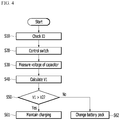
FIG. 4 illustrates a flowchart of a battery charging method according to an embodiment. - Hereinafter, exemplary embodiments disclosed in the present specification will be described in detail with reference to the accompanying drawings. In the present specification, the same or similar constituent elements will be denoted by the same or similar reference numerals, and an overlapped description thereof will be omitted. The terms "module" and "unit" representing constituent elements used in the following description are used only in order to make understanding of the specification easier. Therefore, these terms do not have meanings or roles that distinguish them from each other by themselves. In addition, in describing exemplary embodiments of the present specification, when it is determined that a detailed description of the well-known art associated with the present invention may obscure the gist of the present invention, it will be omitted. Further, the accompanying drawings are provided only in order to allow embodiments disclosed in the present specification to be easily understood and are not to be interpreted as limiting the spirit disclosed in the present specification, and it is to be understood that the present invention includes all modifications, equivalents, and substitutions without departing from the scope and spirit of the present invention.
- Terms including ordinal numbers such as first, second, and the like will be used only to describe various constituent elements, and are not to be interpreted as limiting these constituent elements. The terms are only used to differentiate one constituent element from other constituent elements.
- Singular forms are intended to include plural forms unless the context clearly indicates otherwise.
- It will be further understood that terms "comprises" or "have" used in the present specification specify the presence of stated features, numerals, steps, operations, constituent elements, parts, or a combination thereof, but do not preclude the presence or addition of one or more other features, numerals, steps, operations, constituent elements, parts, or a combination thereof.
- Hereinafter, a battery charging system according to an embodiment will be described with reference to
FIG. 1 to FIG. 3 . -
FIG. 1 illustrates a block diagram of a configuration of a battery charging system according to an embodiment. -
FIG. 2A illustrates a first path of a battery charging system according to an embodiment. -
FIG. 2B illustrates a second path of a battery charging system according to an embodiment. -
FIG. 3A illustrates a third path of a battery charging system according to an embodiment. -
FIG. 3B illustrates a fourth path of a battery charging system according to an embodiment. - Referring to
FIG. 1 , abattery charging system 1 according to an embodiment includes afirst battery pack 10 and asecond battery pack 20. - The
first battery pack 10 and thesecond battery pack 20 may be connected in a non-contact wireless power transmission connection (hereinafter, referred to as a non-contact connection) to supply power to each other. The non-contact connection in the present invention may be a connection using an inductive coupling method, a radiation method, a non-radiation method, a long-distance method, and the like except for a physical connection using a connector, but is not limited thereto. Thefirst battery pack 10 and thesecond battery pack 20 are complementary, and one having a high voltage pack among two battery packs may charge the other having a low voltage. In addition, thefirst battery pack 10 may be an auxiliary battery, and thesecond battery pack 20 may be a main battery, but the present invention is not limited thereto. - The
first battery pack 10 includes afirst communication module 11, afirst battery 12, a first switch S1, a second switch S2, a first diode D1, a first capacitor C1, a first coil CL1 a, a second coil CL1b , two connectors CN1, and afirst BMS 13. - When the
first battery pack 10 and thesecond battery pack 20 are connected in a non-contact connection, thefirst communication module 11 transmits and receives respective unique IDs included in thefirst communication module 11 and thesecond communication module 21. When a unique ID received from thesecond battery pack 20 and a unique ID of thefirst communication module 11 match, thefirst communication module 11 may transmit a matching signal to thefirst BMS 13. Thefirst communication module 11 may transmit a change signal to thesecond communication module 21. Thefirst communication module 11 may be a wireless communication module such as an NFC module or an RFID module, but is not limited thereto. - The
first battery 12 includes a plurality of cells C, may be connected to a motor M (seeFIG. 3A ) through the two connectors CN1, and may be charged with power of thesecond battery 22 through a non-contact connection. - The
first BMS 13 measures a voltage of the first battery 12 (hereinafter, a first voltage V1), and applies a first pulse width modulation (PWM) signal having a predetermined duty cycle to the first switch S1 according to the matching signal or the change signal to control a switching operation of the first switch S1. Thefirst BMS 13 controls a switching operation of the second switch S2 by using a first control signal. - The first switch S1 is connected between a positive electrode of the
first battery 12 and one end of the first coil CL1a, and is on/off-controlled according to the first PWM signal. - The second switch S2 is connected between a negative electrode of the
first battery 12 and one end of the second coil CL1b, and is on/off-controlled according to the first control signal. - The first diode D1 includes a cathode connected to the positive electrode of the
first battery 12 and an anode connected to the other end of the second coil CL1b. - The first capacitor C1 is connected between a first node N1 and a second node N2.
- The first coil CL1a includes one end connected to the first switch S1 and the other end connected to the negative electrode of the
first battery 12. - The second coil CL1b includes one end connected to the second switch S2 and the other end connected to the anode of the first diode D1.
- The
second battery pack 20 includes asecond communication module 21, asecond battery 22, a third switch S3, a fourth switch S4, a second diode D2, a second capacitor C2, a third coil CL2a, a fourth coil CL2b, two connectors CN2, and asecond BMS 23. - When the
first battery pack 10 and thesecond battery pack 20 are connected in a non-contact connection, thesecond communication module 21 transmits and receives respective unique IDs included in thefirst communication module 11 and thesecond communication module 21. When a unique ID received from thefirst battery pack 10 and a unique ID of thesecond communication module 21 match, thesecond communication module 21 may transmit a matching signal to thesecond BMS 23. Thesecond communication module 21 may be a wireless communication module such as an NFC module or an RFID module, but is not limited thereto. Thesecond communication module 21 may transmit a change signal to thefirst communication module 11. - The
second battery 22 includes a plurality of cells C, may be connected to a motor M (seeFIG. 2A ) through the two connectors CN2, and may be charged with power of thefirst battery 12 through a non-contact connection. - The
second BMS 23 measures a voltage of the second battery 22 (hereinafter, a second voltage V2), and applies a second pulse width modulation (PWM) signal having a predetermined duty cycle to the third switch S3 according to the matching signal or the change signal to control a switching operation of the third switch S3. Thesecond BMS 23 controls a switching operation of the fourth switch S4 by using a second control signal. When the first voltage V1 is lower than the second voltage V2, thesecond BMS 23 may generate a change signal for changing a battery pack to be charged. - The third switch S3 is connected between a positive electrode of the
second battery 22 and one end of the third coil CL2a, and is on/off-controlled according to the second PWM signal. - The fourth switch S4 is connected between a negative electrode of the
second battery 22 and one end of the fourth coil CL2b, and is on/off-controlled according to the second control signal. - The second diode D1 includes a cathode connected to the positive electrode of the
second battery 22 and an anode connected to the other end of the fourth coil CL2b. - The second capacitor C2 is connected between a third node N3 and a fourth node N4.
- The third coil CL2a includes one end connected to the third switch S3 and the other end connected to the negative electrode of the
second battery 22. - The fourth coil CL2b includes one end connected to the fourth switch S4 and the other end connected to the anode of the second diode D2.
- Hereinafter, a charging path of an embodiment in which the
first battery pack 10 and thesecond battery pack 20 are connected in a non-contact connection and thesecond battery pack 20 is charged with thefirst battery pack 10 will be described with reference toFIG. 2A andFIG. 2B .FIG. 2A illustrates a first path of a battery charging system according to an embodiment.FIG. 2B illustrates a second path of a battery charging system according to an embodiment. - The
first BMS 13 controls the first switch S1 to perform a switching operation, that is, an on operation and an off operation once, according to the matching signal, and controls the second switch S2 to be turned off. In this case, thesecond BMS 23 controls the third switch S3 to be turned off and the fourth switch S4 to be turned on. The motor M may be connected to two connectors CN2. In addition, the first coil CL1a operates as a primary coil, and the fourth coil CL2b operates as a secondary coil. - First, referring to
FIG. 2A , when the first switch S1 is turned on, a current flows into the first coil CL1a through a first path Ro1 passing through the first switch S1 and the first coil CL1a. - The positive electrode of the
second battery 22 is connected to the cathode of the second diode D2, and the negative electrode of thesecond battery 22 is connected to the anode thereof. Therefore, since a reverse voltage is applied to the second diode D2, no current flows through the second diode D2. In this case, the second capacitor C2 is charged with the second voltage V2. - Next, referring to
FIG. 2B , when the first switch S1 is turned off, as no current is supplied to the first coil CL1a, counter electromotive force corresponding to the first voltage V1 is generated, and a current corresponding to the counter electromotive force flows into the fourth coil CL2b, which is a secondary coil. That is, a current corresponding to the first voltage V1 flows through a second path Rf1 passing through the fourth coil CL2b and the second diode D2. Therefore, a potential difference corresponding to a sum (V1+V2) of the first voltage V1 and the second voltage V2 is generated between the third node N3 and the fourth node N4. - The
second BMS 23 measures voltages (V1+V2) of both ends of the second capacitor C2 by using a voltage between the third node N3 and the fourth node N4, and calculates the first voltage V1 by usingEquation 1 below.
- The
second BMS 23 compares the calculated first voltage V1 and the second voltage V2, and when the first voltage V1 is higher than the second voltage V2, thesecond BMS 23 controls the first switch S1 to perform the switching operation a reference number of times (for example, 10 times). - The
second BMS 23 generates a change signal such that when the first voltage V1 is lower than the second voltage V2, thefirst battery pack 10 is charged with thesecond battery pack 20 by changing the battery pack. - Hereinafter, a charging path of an embodiment in which the
first battery pack 10 and thesecond battery pack 20 are connected in a non-contact connection and thefirst battery pack 10 is charged with thesecond battery pack 20 will be described with reference toFIG. 3A andFIG. 3B .FIG. 3A illustrates a third path of a battery charging system according to an embodiment.FIG. 3B illustrates a fourth path of a battery charging system according to an embodiment. - The
first BMS 23 controls the third switch S3 to perform a switching operation, that is, an on operation and an off operation once, according to the change signal, and controls the fourth switch S4 to be turned off. In this case, thefirst BMS 13 controls the first switch S1 to be off and the second switch S2 to be on. The motor M may be connected to two connectors CN1. In addition, the third coil CL2a operates as a primary coil, and the second coil CL1b operates as a secondary coil. - First, referring to
FIG. 3A , when the third switch S3 is turned on, a current flows into the third coil CL2a through a third path Ro2 passing through the third switch S3 and the third coil CL2a. - The positive electrode of the
first battery 12 is connected to the cathode of the first diode D1, and the negative electrode of thefirst battery 12 is connected to the anode thereof. Therefore, since a reverse voltage is applied to the first diode D1, no current flows through the first diode D1. In this case, the first capacitor C1 is charged with the first voltage V1. - Next, referring to
FIG. 3B , when the third switch S3 is turned off, as no current is supplied to the third coil CL2a, counter electromotive force corresponding to the second voltage V2 is generated, and a current corresponding to the counter electromotive force flows into the second coil CL1b, which is a secondary coil. That is, a current corresponding to the second voltage V2 flows through a fourth path Rf2 passing through the second coil CL1b and the first diode D1. Therefore, a potential difference corresponding to a sum (V1+V2) of the first voltage V1 and the second voltage V2 is generated between the first node N1 and the second node N2. - The
first BMS 13 measures voltages (V1+V2) of both ends of the first capacitor C1 by using a voltage between the first node N1 and the second node N2, and calculates the second voltage V2 by usingEquation 2 below.
- The
first BMS 13 compares the calculated second voltage V2 and the first voltage V1, and when the second voltage V2 is higher than the first voltage V1, thefirst BMS 13 controls the third switch S3 to perform the switching operation a reference number of times. - The
first BMS 13 generates a change signal such that when the second voltage V2 is lower than the first voltage V1, thesecond battery pack 20 is charged with thefirst battery pack 10 by changing the battery pack. - An embodiment in which the
second battery pack 20 is charged with thefirst battery pack 10 is described in detail with reference toFIG. 2 , thus is omitted. - Therefore, when there is no information on the first voltage V1, the
battery charging system 1 according to the embodiment may calculate the first voltage V1 to charge a battery having a low voltage with a battery having a higher voltage among thefirst battery 12 and thesecond battery 22, and when there is no information on the second voltage V2, it may calculate the second voltage V2 to charge a battery having a low voltage with a battery having a higher voltage among thefirst battery 12 and thesecond battery 22, thus the voltage difference between the main battery and the auxiliary battery may be minimized. - Hereinafter, a battery charging method according to an embodiment will be described with reference to
FIG. 4 . - At step S10, when the
first battery pack 10 and thesecond battery pack 20 are connected in a non-contact connection, thefirst communication module 11 transmits and receives respective unique IDs included in thefirst communication module 11 and thesecond communication module 21, and when the unique ID of thefirst communication module 11 is matched, the matching signal is transmitted to thefirst BMS 13 to check the unique ID. - At step S20, the
first BMS 13 controls the first switch S1 to perform an on operation and an off operation once, according to the matching signal, and controls the second switch S2 to be turned off. In this case, thesecond BMS 23 controls the third switch S3 to be turned off and the fourth switch S4 to be turned on. - At step S30, the
second BMS 23 measures a voltage between the third node N3 and the fourth node N4 to measure voltages of both ends the second capacitor C2. - At step S40, the
second BMS 23 calculates the first voltage V1 byEquation 1. - At step S50, the
second BMS 23 compares the first voltage V1 and the second voltage V2 that are calculated by using the calculated first voltage V1. - At step S61, when the voltage V1 is higher than the second voltage V2, the
second BMS 23 controls the first switch S1 to perform the switching operation a reference number of times to maintain charging. - At step S62, the
second BMS 23 generates a change signal such that when the first voltage V1 is lower than the second voltage V2, thefirst battery pack 10 is charged with thesecond battery pack 20 so that the battery pack is changed. - For convenience of description, it has been described that the
battery charging system 1 according to the embodiment includes two battery packs, but is not limited thereto, and may include two or more battery packs. - In addition, while this invention has been described in connection with what is presently considered to be practical exemplary embodiments, it is to be understood that the invention is not limited to the disclosed embodiments, but, on the contrary, is intended to cover various modifications and equivalent arrangements included within the spirit and scope of the appended claims. Therefore, the above-detailed description is not to be interpreted as being restrictive, but is to be considered as being illustrative. The scope of the present invention is to be determined by reasonable interpretation of the claims, and all alterations within equivalences of the present invention fall within the scope of the present invention.
Claims (17)
- A battery charging system, comprising:a first battery pack; anda second battery pack,wherein the first battery pack includes a first battery;the second battery pack includes a second battery, a first capacitor connected in series between a positive electrode and a negative electrode of the second battery, and a first BMS configured to measure a voltage of the second battery and voltages of both ends of the second capacitor;the first BMS is configured to calculate a voltage of the first battery by using the voltages of the both ends, to compare the voltage of the first battery with the voltage of the second battery, to charge the second battery with a voltage of the first battery when the first battery voltage is higher than the second battery voltage, and to charge the first battery with a voltage of the second battery when the first battery voltage is lower than the second battery voltage; andthe first battery pack and the second battery pack are charged by a non-contact connection.
- The battery charging system of claim 1, wherein
the first battery pack further includes a first switch and a first coil connected in series between the positive electrode and the negative electrode of the first battery, and a second BMS configured to control the first switch to a first state or a second state;
the second battery pack further includes a second coil connected in series between the positive electrode and the negative electrode of the second battery; and
the first coil is a primary coil for wireless power transmission between the first battery and the second battery, and the second coil is a secondary coil for the wireless power transmission. - The battery charging system of claim 2, wherein
in the first state of the first switch, a current of the first battery flows through the first coil, and
in the second state of the first switch, a current corresponding to counter electromotive force of the first battery voltage flows through the second coil. - The battery charging system of claim 3, wherein
the first capacitor is charged with the voltage of the second battery voltage in the first state of the first switch, and is charged with a voltage corresponding to a sum of the voltage of the first battery and the voltage of the second battery in the second state of the first switch. - The battery charging system of claim 4, wherein
the second battery pack further includes:a first diode connected in parallel to the first capacitor; anda second switch connected between the negative electrode of the second battery and the second coil. - The battery charging system of claim 5, wherein
the first battery pack further includes a second capacitor, a third coil, and a third switch that are connected in series to each other between the positive electrode and the negative electrode of the first battery;
the second battery pack further includes a fourth coil that is connected in series to and between the positive electrode and the negative electrode of the second battery; and
the first BMS is configured to control the fourth switch to a first state or a second state. - The battery charging system of claim 6, wherein
when the voltage of the first battery voltage is lower than that of the second battery,
a current of the second battery flows through the fourth coil in the first state of the fourth switch, and
a current corresponding to counter electromotive force of the voltage of the second battery flows through the third coil in the second state of the fourth switch. - The battery charging system of claim 7, wherein
the second capacitor is charged with the second battery voltage in the first state of the fourth switch, and is charged with a voltage corresponding to a sum of the voltage of the first battery and the voltage of the second battery in the second state of the fourth switch. - The battery charging system of claim 8, wherein
the first battery pack further includes:a second diode connected in parallel to the second capacitor; anda fourth switch connected between the negative electrode of the first battery and the third coil. - The battery charging system of claim 9, wherein
the first battery pack further includes a first communication module having a unique ID,
the second battery pack further includes a second communication module wireless-communicating with the first communication module and having a unique ID, and
when the first battery pack and the second battery pack are connected in the non-contact connection, the first communication module and the second communication module respectively transmit and receive the unique IDs to generate a matching signal when the unique IDs match each other. - The battery charging system of claim 10, wherein
the first BMS controls the first switch according to the matching signal, and
the second BMS controls the fourth switch according to the matching signal. - A battery charging method, comprising:a first battery pack; anda second battery pack,wherein the first battery pack includes a first battery, a first switch and a first coil connected in series between positive and negative electrodes of the first battery, and a first communication module including a unique ID; and the second battery pack includes a second battery, a first capacitor connected in series between positive and negative electrodes of the second battery, and a second communication module wireless-communicating with the first communication module and having a unique ID, andgenerating a matching signal when the first communication module and the second communication module respectively transmit and receive the unique IDs and then the unique IDs match each other in a case that the first battery pack and the second battery pack are connected;controlling the first switch according to the matching signal;measuring a voltage of the second battery;calculating a sum of a voltage of the first battery and a voltage of the second battery by using voltages of both ends of the first capacitor;calculating a voltage of the first battery by using the sum of the voltage of the first battery and the voltage of the second battery; andcomparing the voltage of the first battery with the voltage of the second battery, and controlling a switching operation of the first switch by a reference number of times when the voltage of the first battery is higher than the voltage of the second battery; andthe connection is a non-contact connection.
- The battery charging method of claim 12, wherein
the second battery pack further includes a first diode connected in parallel to the first capacitor and a second switch connected between a negative electrode of the second battery and the second coil;
the first battery pack further includes a third switch connected between a positive electrode and a negative electrode of the first battery, a second capacitor connected between the positive electrode and the negative electrode of the first battery, a second diode connected in parallel to the second capacitor, and a fourth switch connected between the negative electrode of the first battery and the third coil; and
the controlling of the first switch according to the matching signal includes
controlling the first switch to a first state, and
controlling the first switch to a second state. - The battery charging method of claim 13, further comprising,
after the controlling of the first switch to the first state:controlling the third switch to the second state; andcontrolling the fourth switch to the second state. - The battery charging method of claim 14, wherein
the calculating of the sum of the voltage of the first battery and the voltage of the second battery by using the voltages of both ends of the first capacitor is
calculating the sum of the voltage of the first battery and the voltage of the second battery by using the voltages of both ends the first capacitor after the controlling of the first switch to the second state. - The battery charging method of claim 15, wherein
the calculating of the voltage of the first battery by using the sum of the voltage of the first battery and the voltage of the second battery is
calculating the voltage of the first battery by using the sum of the voltage of the first battery and the voltage of the second battery after the controlling of the first switch to the second state. - The battery charging method of claim 16, further comprising
comparing the voltage of the first battery with the voltage of the second battery, and when the voltage of the second battery is higher than the voltage of the first battery, charging the first battery with the second battery.
Applications Claiming Priority (2)
| Application Number | Priority Date | Filing Date | Title |
|---|---|---|---|
| KR1020190005245A KR102711943B1 (en) | 2019-01-15 | 2019-01-15 | Battery charging system and battery charging mehod |
| PCT/KR2019/017908 WO2020149537A1 (en) | 2019-01-15 | 2019-12-17 | Battery charging system and battery charging method |
Publications (2)
| Publication Number | Publication Date |
|---|---|
| EP3842283A1 true EP3842283A1 (en) | 2021-06-30 |
| EP3842283A4 EP3842283A4 (en) | 2021-11-03 |
Family
ID=71613220
Family Applications (1)
| Application Number | Title | Priority Date | Filing Date |
|---|---|---|---|
| EP19910649.3A Pending EP3842283A4 (en) | 2019-01-15 | 2019-12-17 | BATTERY CHARGING SYSTEM AND METHOD |
Country Status (6)
| Country | Link |
|---|---|
| US (1) | US11981219B2 (en) |
| EP (1) | EP3842283A4 (en) |
| JP (1) | JP7199631B2 (en) |
| KR (1) | KR102711943B1 (en) |
| CN (1) | CN112770932B (en) |
| WO (1) | WO2020149537A1 (en) |
Families Citing this family (7)
| Publication number | Priority date | Publication date | Assignee | Title |
|---|---|---|---|---|
| KR102711943B1 (en) * | 2019-01-15 | 2024-09-27 | 주식회사 엘지에너지솔루션 | Battery charging system and battery charging mehod |
| KR102679823B1 (en) * | 2019-09-06 | 2024-07-03 | 주식회사 엘지에너지솔루션 | Battery system and controlling method of the same |
| CN114379382B (en) * | 2020-10-16 | 2023-05-23 | 宇通客车股份有限公司 | Double-power-system passenger car and charging method thereof |
| CN114362326B (en) * | 2022-01-28 | 2024-07-16 | 北京小米移动软件有限公司 | Charging and discharging system, method, device, terminal equipment and storage medium |
| CN117294028A (en) * | 2022-06-16 | 2023-12-26 | 深圳市启天太一科技有限公司 | An electromagnetic coupling energy transmission system |
| EP4398447A4 (en) * | 2022-11-15 | 2025-12-03 | Samsung Electronics Co Ltd | ELECTRONIC DEVICE AND POWER CONTROL METHOD BASED ON A MULTIPLE OF BATTERIES IN AN ELECTRONIC DEVICE |
| CN115498747B (en) * | 2022-11-22 | 2023-03-24 | 广州疆海科技有限公司 | Energy storage parallel operation equipment and energy storage parallel operation method |
Family Cites Families (25)
| Publication number | Priority date | Publication date | Assignee | Title |
|---|---|---|---|---|
| JP3392214B2 (en) | 1994-05-25 | 2003-03-31 | 株式会社岡村研究所 | Battery charge control device and method |
| FR2803447B1 (en) | 1999-12-30 | 2003-08-29 | Renault | POWER GENERATION SYSTEM FOR A TWO-VOLTAGE NETWORK |
| US20070257642A1 (en) | 2003-06-19 | 2007-11-08 | Sean Xiao | Battery cell monitoring and balancing circuit |
| JP2006280173A (en) | 2005-03-30 | 2006-10-12 | Kyocera Corp | Power supply system and battery pack |
| JP4441920B2 (en) | 2007-11-22 | 2010-03-31 | 株式会社デンソー | Power supply |
| JP2010028916A (en) * | 2008-07-16 | 2010-02-04 | Fujifilm Corp | Power supply and method of controlling the same, and program |
| JP2010028918A (en) | 2008-07-16 | 2010-02-04 | Mitsuba Corp | Cooling structure of electric motor |
| KR101097263B1 (en) * | 2009-12-28 | 2011-12-21 | 삼성에스디아이 주식회사 | Battery pack and its charging control method |
| TWM392484U (en) | 2010-06-30 | 2010-11-11 | ming-xiang Ye | Bidirectional wireless charge and discharge device |
| CN103493331B (en) | 2011-04-19 | 2016-06-08 | 新电元工业株式会社 | Unit balancing circuitry and unit bascule |
| KR101263463B1 (en) | 2011-09-02 | 2013-05-10 | 주식회사 만도 | Apparatus for charging battery |
| JP2014003835A (en) * | 2012-06-20 | 2014-01-09 | Nikon Corp | Electronic apparatus, power control system, and power control unit |
| JP5929703B2 (en) | 2012-10-22 | 2016-06-08 | 三菱電機株式会社 | DC / DC converter |
| DE102013200674A1 (en) * | 2013-01-17 | 2014-07-17 | Bayerische Motoren Werke Aktiengesellschaft | Vehicle with an electric machine and two sub-nets |
| US9641012B2 (en) | 2014-04-18 | 2017-05-02 | Medtronic, Inc. | Methods, implantable medical devices, and systems that abort a high voltage charge when a transformer is impaired |
| KR20150121639A (en) * | 2014-04-21 | 2015-10-29 | 삼성전기주식회사 | Controlling circuit for Hybrid Electric Vehicle and Controlling method thereof |
| US9493091B2 (en) | 2014-04-21 | 2016-11-15 | Samsung Electro-Mechanics Co., Ltd. | Driving circuit for hybrid electric vehicle and controlling method thereof |
| KR20150142215A (en) * | 2014-06-11 | 2015-12-22 | 주식회사 켐트로닉스 | Auxiliary battery having removable disk with transmitter-receiver wireless charge and method for transmitting power and data thereof |
| JP6394368B2 (en) * | 2014-12-24 | 2018-09-26 | トヨタ自動車株式会社 | Electric car |
| DE102015204704B4 (en) | 2015-03-16 | 2020-02-20 | Deutsche Telekom Ag | Method for communication between at least a first and a second telecommunication terminal, each with a long-range communication interface, a short-range communication interface, an energy store and in each case an energy transmission interface, telecommunication terminal, system, computer program and computer program product |
| JP6455332B2 (en) | 2015-06-22 | 2019-01-23 | 株式会社Soken | Non-contact power feeding device |
| CN106891765A (en) * | 2017-03-01 | 2017-06-27 | 国网上海市电力公司 | A kind of CAN interface for vehicle-mounted mobile charging device |
| CN109066917A (en) * | 2018-09-28 | 2018-12-21 | 北京新能源汽车股份有限公司 | A battery system and charging method |
| US20200222703A1 (en) * | 2019-01-10 | 2020-07-16 | Stimwave Technologies Incorporated | Wireless implantable pulse generators |
| KR102711943B1 (en) * | 2019-01-15 | 2024-09-27 | 주식회사 엘지에너지솔루션 | Battery charging system and battery charging mehod |
-
2019
- 2019-01-15 KR KR1020190005245A patent/KR102711943B1/en active Active
- 2019-12-17 WO PCT/KR2019/017908 patent/WO2020149537A1/en not_active Ceased
- 2019-12-17 EP EP19910649.3A patent/EP3842283A4/en active Pending
- 2019-12-17 CN CN201980064022.5A patent/CN112770932B/en active Active
- 2019-12-17 JP JP2021512553A patent/JP7199631B2/en active Active
- 2019-12-17 US US17/280,578 patent/US11981219B2/en active Active
Also Published As
| Publication number | Publication date |
|---|---|
| JP7199631B2 (en) | 2023-01-06 |
| CN112770932B (en) | 2024-04-26 |
| US20220001755A1 (en) | 2022-01-06 |
| KR20200088663A (en) | 2020-07-23 |
| KR102711943B1 (en) | 2024-09-27 |
| JP2021536213A (en) | 2021-12-23 |
| US11981219B2 (en) | 2024-05-14 |
| WO2020149537A1 (en) | 2020-07-23 |
| EP3842283A4 (en) | 2021-11-03 |
| CN112770932A (en) | 2021-05-07 |
Similar Documents
| Publication | Publication Date | Title |
|---|---|---|
| EP3842283A1 (en) | Battery charging system and battery charging method | |
| KR101305605B1 (en) | Electric Vehicle Power Supply System | |
| US7880433B2 (en) | Charge equalization apparatus | |
| KR101677679B1 (en) | Power management circuit for rechargeable battery stack | |
| KR101165593B1 (en) | A cell balancing circuit device of battery management system using bidirectional dc-dc converter | |
| EP2221937B1 (en) | Built-in charge circuit for secondary battery and secondary battery with the built-in charge circuit | |
| US20140035531A1 (en) | Charge balancing system for batteries | |
| US12179622B2 (en) | Battery pack charging system | |
| US20130181514A1 (en) | Power source apparatus | |
| US10322687B2 (en) | Stabilization circuit for a vehicle electrical system | |
| KR20210022418A (en) | Battery system and operating method thereof | |
| KR20120112066A (en) | Auxiliary battery charging apparatus | |
| KR20170039477A (en) | Apparatus for balancing battery stack | |
| KR101305759B1 (en) | Power supply system for electric vehicle | |
| EP4080704A1 (en) | Power source device for vehicles | |
| EP3413434B1 (en) | Power supply system and power transmission circuit | |
| US20150153423A1 (en) | Method and a Device for Determining the Internal Resistance of Battery Cells of a Battery | |
| EP4238805A1 (en) | Vehicle power source device | |
| US11095128B2 (en) | Voltage balance correction circuit | |
| JP2015042013A (en) | Charging device | |
| JP5604947B2 (en) | Power supply device and voltage adjustment method | |
| EP3413435B1 (en) | Power feed system and power transmission circuit | |
| KR102642061B1 (en) | Apparatus for driving relay of electric vehicle | |
| JP3206251U (en) | Capacitor unit, power receiving system and automatic guided vehicle | |
| US20140117935A1 (en) | Device and method for balancing battery cells |
Legal Events
| Date | Code | Title | Description |
|---|---|---|---|
| STAA | Information on the status of an ep patent application or granted ep patent |
Free format text: STATUS: THE INTERNATIONAL PUBLICATION HAS BEEN MADE |
|
| PUAI | Public reference made under article 153(3) epc to a published international application that has entered the european phase |
Free format text: ORIGINAL CODE: 0009012 |
|
| STAA | Information on the status of an ep patent application or granted ep patent |
Free format text: STATUS: REQUEST FOR EXAMINATION WAS MADE |
|
| 17P | Request for examination filed |
Effective date: 20210326 |
|
| AK | Designated contracting states |
Kind code of ref document: A1 Designated state(s): AL AT BE BG CH CY CZ DE DK EE ES FI FR GB GR HR HU IE IS IT LI LT LU LV MC MK MT NL NO PL PT RO RS SE SI SK SM TR |
|
| A4 | Supplementary search report drawn up and despatched |
Effective date: 20211005 |
|
| RIC1 | Information provided on ipc code assigned before grant |
Ipc: B60L 53/34 20190101ALI20210929BHEP Ipc: B60L 58/18 20190101ALI20210929BHEP Ipc: B60L 53/122 20190101AFI20210929BHEP |
|
| RAP1 | Party data changed (applicant data changed or rights of an application transferred) |
Owner name: LG ENERGY SOLUTION LTD. |
|
| RAP3 | Party data changed (applicant data changed or rights of an application transferred) |
Owner name: LG ENERGY SOLUTION, LTD. |
|
| DAV | Request for validation of the european patent (deleted) | ||
| DAX | Request for extension of the european patent (deleted) | ||
| STAA | Information on the status of an ep patent application or granted ep patent |
Free format text: STATUS: EXAMINATION IS IN PROGRESS |
|
| 17Q | First examination report despatched |
Effective date: 20260206 |