EP3842268A1 - Vehicle door system and control method thereof, and vehicle having same - Google Patents
Vehicle door system and control method thereof, and vehicle having same Download PDFInfo
- Publication number
- EP3842268A1 EP3842268A1 EP19858789.1A EP19858789A EP3842268A1 EP 3842268 A1 EP3842268 A1 EP 3842268A1 EP 19858789 A EP19858789 A EP 19858789A EP 3842268 A1 EP3842268 A1 EP 3842268A1
- Authority
- EP
- European Patent Office
- Prior art keywords
- door
- doorway
- opening
- rim
- vehicle
- Prior art date
- Legal status (The legal status is an assumption and is not a legal conclusion. Google has not performed a legal analysis and makes no representation as to the accuracy of the status listed.)
- Granted
Links
Images






Classifications
-
- B—PERFORMING OPERATIONS; TRANSPORTING
- B60—VEHICLES IN GENERAL
- B60J—WINDOWS, WINDSCREENS, NON-FIXED ROOFS, DOORS, OR SIMILAR DEVICES FOR VEHICLES; REMOVABLE EXTERNAL PROTECTIVE COVERINGS SPECIALLY ADAPTED FOR VEHICLES
- B60J7/00—Non-fixed roofs; Roofs with movable panels, e.g. rotary sunroofs
- B60J7/08—Non-fixed roofs; Roofs with movable panels, e.g. rotary sunroofs of non-sliding type, i.e. movable or removable roofs or panels, e.g. let-down tops or roofs capable of being easily detached or of assuming a collapsed or inoperative position
- B60J7/16—Non-fixed roofs; Roofs with movable panels, e.g. rotary sunroofs of non-sliding type, i.e. movable or removable roofs or panels, e.g. let-down tops or roofs capable of being easily detached or of assuming a collapsed or inoperative position non-foldable and rigid, e.g. a one-piece hard-top or a single rigid roof panel
- B60J7/1628—Non-fixed roofs; Roofs with movable panels, e.g. rotary sunroofs of non-sliding type, i.e. movable or removable roofs or panels, e.g. let-down tops or roofs capable of being easily detached or of assuming a collapsed or inoperative position non-foldable and rigid, e.g. a one-piece hard-top or a single rigid roof panel for covering the passenger compartment
- B60J7/1635—Non-fixed roofs; Roofs with movable panels, e.g. rotary sunroofs of non-sliding type, i.e. movable or removable roofs or panels, e.g. let-down tops or roofs capable of being easily detached or of assuming a collapsed or inoperative position non-foldable and rigid, e.g. a one-piece hard-top or a single rigid roof panel for covering the passenger compartment of non-convertible vehicles
- B60J7/1657—Non-fixed roofs; Roofs with movable panels, e.g. rotary sunroofs of non-sliding type, i.e. movable or removable roofs or panels, e.g. let-down tops or roofs capable of being easily detached or of assuming a collapsed or inoperative position non-foldable and rigid, e.g. a one-piece hard-top or a single rigid roof panel for covering the passenger compartment of non-convertible vehicles at least a major part of the roof pivoting about a stationary axis
-
- B—PERFORMING OPERATIONS; TRANSPORTING
- B60—VEHICLES IN GENERAL
- B60J—WINDOWS, WINDSCREENS, NON-FIXED ROOFS, DOORS, OR SIMILAR DEVICES FOR VEHICLES; REMOVABLE EXTERNAL PROTECTIVE COVERINGS SPECIALLY ADAPTED FOR VEHICLES
- B60J5/00—Doors
- B60J5/04—Doors arranged at the vehicle sides
- B60J5/047—Doors arranged at the vehicle sides characterised by the opening or closing movement
- B60J5/0477—Doors arranged at the vehicle sides characterised by the opening or closing movement with two doors opening in opposite direction
-
- B—PERFORMING OPERATIONS; TRANSPORTING
- B60—VEHICLES IN GENERAL
- B60J—WINDOWS, WINDSCREENS, NON-FIXED ROOFS, DOORS, OR SIMILAR DEVICES FOR VEHICLES; REMOVABLE EXTERNAL PROTECTIVE COVERINGS SPECIALLY ADAPTED FOR VEHICLES
- B60J5/00—Doors
- B60J5/04—Doors arranged at the vehicle sides
- B60J5/06—Doors arranged at the vehicle sides slidable; foldable
-
- E—FIXED CONSTRUCTIONS
- E05—LOCKS; KEYS; WINDOW OR DOOR FITTINGS; SAFES
- E05Y—INDEXING SCHEME ASSOCIATED WITH SUBCLASSES E05D AND E05F, RELATING TO CONSTRUCTION ELEMENTS, ELECTRIC CONTROL, POWER SUPPLY, POWER SIGNAL OR TRANSMISSION, USER INTERFACES, MOUNTING OR COUPLING, DETAILS, ACCESSORIES, AUXILIARY OPERATIONS NOT OTHERWISE PROVIDED FOR, APPLICATION THEREOF
- E05Y2400/00—Electronic control; Electrical power; Power supply; Power or signal transmission; User interfaces
- E05Y2400/10—Electronic control
- E05Y2400/45—Control modes
-
- E—FIXED CONSTRUCTIONS
- E05—LOCKS; KEYS; WINDOW OR DOOR FITTINGS; SAFES
- E05Y—INDEXING SCHEME ASSOCIATED WITH SUBCLASSES E05D AND E05F, RELATING TO CONSTRUCTION ELEMENTS, ELECTRIC CONTROL, POWER SUPPLY, POWER SIGNAL OR TRANSMISSION, USER INTERFACES, MOUNTING OR COUPLING, DETAILS, ACCESSORIES, AUXILIARY OPERATIONS NOT OTHERWISE PROVIDED FOR, APPLICATION THEREOF
- E05Y2400/00—Electronic control; Electrical power; Power supply; Power or signal transmission; User interfaces
- E05Y2400/10—Electronic control
- E05Y2400/52—Safety arrangements associated with the wing motor
- E05Y2400/53—Wing impact prevention or reduction
- E05Y2400/54—Obstruction or resistance detection
-
- E—FIXED CONSTRUCTIONS
- E05—LOCKS; KEYS; WINDOW OR DOOR FITTINGS; SAFES
- E05Y—INDEXING SCHEME ASSOCIATED WITH SUBCLASSES E05D AND E05F, RELATING TO CONSTRUCTION ELEMENTS, ELECTRIC CONTROL, POWER SUPPLY, POWER SIGNAL OR TRANSMISSION, USER INTERFACES, MOUNTING OR COUPLING, DETAILS, ACCESSORIES, AUXILIARY OPERATIONS NOT OTHERWISE PROVIDED FOR, APPLICATION THEREOF
- E05Y2900/00—Application of doors, windows, wings or fittings thereof
- E05Y2900/50—Application of doors, windows, wings or fittings thereof for vehicles
- E05Y2900/53—Type of wing
- E05Y2900/531—Doors
-
- E—FIXED CONSTRUCTIONS
- E05—LOCKS; KEYS; WINDOW OR DOOR FITTINGS; SAFES
- E05Y—INDEXING SCHEME ASSOCIATED WITH SUBCLASSES E05D AND E05F, RELATING TO CONSTRUCTION ELEMENTS, ELECTRIC CONTROL, POWER SUPPLY, POWER SIGNAL OR TRANSMISSION, USER INTERFACES, MOUNTING OR COUPLING, DETAILS, ACCESSORIES, AUXILIARY OPERATIONS NOT OTHERWISE PROVIDED FOR, APPLICATION THEREOF
- E05Y2900/00—Application of doors, windows, wings or fittings thereof
- E05Y2900/50—Application of doors, windows, wings or fittings thereof for vehicles
- E05Y2900/53—Type of wing
- E05Y2900/542—Roof panels
Definitions
- the present invention relates to the technical field of vehicle, in particular to a vehicle door system and a control method thereof, and a vehicle having the same.
- the vehicle has become an indispensable means of transportation for human beings, and from the tendency of passenger vehicle modeling, making the vehicle body low is beneficial to reducing the wind resistance and increasing the stability, but will cause inconvenience for the passenger to get in and out of the vehicle.
- a supercar with a low vehicle body all manufacturers are exploring novel ways to open the door so as to solve the above problem.
- the top structure and the side structure of the doors are connected, the top portion and the side portion are required to be opened at the same time to realize opening of the vehicle door, then when the vehicle door is opened in rain and snow, rain and snow will easily enter the vehicle body from the opened top portion.
- the present invention provides a vehicle door system and a control method thereof and a vehicle having the same.
- an embodiment of the present invention provides a vehicle door system, including: a top door, the top door opening and closing a first opening of a vehicle body top portion; and a side door, the side door including a side door body and a side window, wherein the side door body opens and closes a second opening of a vehicle body side skirt, the side window is mounted on the side door body, both a top edge and a side edge of the side window are configured to be frameless, and the side window is capable of raising or lowering relative to the side door body; when the side door body closes the second opening, the side window raises or lowers to open or close a third opening of the vehicle body side skirt, wherein the third opening is located above the second opening, and the first opening, the second opening, and the third opening are interconnected.
- the top door has a first rim cooperating with a top edge of the side window, and the first rim is mounted with a sealing member.
- the vehicle body has a doorway
- the doorway includes a top doorway and a side doorway, and wherein the first opening is formed in the top doorway, and the second opening and the third opening are formed in the side doorway.
- the side doorway includes a first side doorway and a second side doorway that are symmetrically provided; the side door includes a first side door and a second side door that are symmetrically provided, wherein the first side door is configured to open and close the first side doorway, and the second side door is configured to open and close the second side doorway; and the top door is connected to a top edge of the first side doorway or a top edge of the second side doorway.
- the doorway includes a first doorway and a second doorway that are symmetrically provided, the first doorway includes a first top doorway and a first side doorway, the second doorway includes a second top doorway and a second side doorway, and the first top doorway and the second top doorway are arranged at an interval;
- the side door includes a first side door and a second side door that are symmetrically provided, the first side door is configured to open and close the first side doorway, and the second side door is configured to open and close the second side doorway;
- the top door includes a first top door and a second top door, the first top door is configured to open or close the first top doorway separately, and the second top door is configured to open or close the second top doorway separately.
- the vehicle door system further includes a first front door and a second front door, wherein the first front door is located between a vehicle body head portion and the first side door, and the second front door is located between the vehicle body head portion and the second side door, and wherein opening directions of the first side door and the first front door are the same or opposite, and opening directions of the second side door and the second front door are the same or opposite.
- the doorway includes at least one pair of first doorway and second doorway that are symmetrically provided, and at least one pair of third doorway and fourth doorway that are symmetrically provided
- the first doorway includes a first top doorway and a first side doorway
- the second doorway includes a second top doorway and a second side doorway
- the third doorway includes a third top doorway and a third side doorway
- the fourth doorway includes a fourth top doorway and a fourth side doorway
- the top door includes a first top door, a second top door, a third top door, and a fourth top door provided corresponding to the first top doorway, the second top doorway, the third top doorway, and the fourth top doorway, respectively.
- first top doorway, the second top doorway, the third top doorway, and the fourth top doorway are interconnected, and the first top door, the second top door, the third top door, and the fourth top door are an integral member so as to simultaneously open or close the first top doorway, the second top doorway, the third top doorway, and the fourth top doorway.
- first top doorway, the second top doorway, the third top doorway, and the fourth top doorway are provided at intervals; and the first top door and the third top door are an integral member so as to simultaneously open or close the first top doorway and the third top doorway, and the second top door and the fourth top door are an integral member so as to simultaneously open or close the second top doorway and the fourth top doorway.
- first top doorway, the second top doorway, the third top doorway, and the fourth top doorway are provided at intervals; and the first top door, the second top door, the third top door, and the fourth top door are separate members to each other, wherein the first top door is configured to separately open or close the first top doorway, the second top door is configured to separately open or close the second top doorway, the third top door is configured to separately open or close the third top doorway, and the fourth top door is configured to separately open or close the fourth top doorway.
- the side door includes a first side door, a second side door, a third side door, and a fourth side door that are provided corresponding to the first side doorway, the second side doorway, the third side doorway, and the fourth side doorway, respectively; and wherein opening directions of the first side door and the third side door are the same or opposite, and opening directions of the second side door and the fourth side door are the same or opposite.
- the vehicle body side skirt has a fourth opening interconnected with the third opening, and the vehicle door system further includes a corner window provided at the fourth opening.
- the corner window is fixed at the fourth opening.
- the corner window is movably provided at the fourth opening so as to open and close the fourth opening.
- the top door has a first rim adjacent to the top edge of the side window, and a second rim extending along a direction of the first rim towards a vehicle body tail portion, the corner window is mounted on the second rim, and the corner window is capable of moving along with the top door so as to open and close the fourth opening.
- a sealing member is provided between a corner window side rim and a side edge of the side window.
- the vehicle door system further includes a first top door lock assembly, wherein the first top door lock assembly includes a first component and a second component, the first component is mounted on the corner window, and the second component is mounted at an edge of the fourth opening, so that the first component and the second component are capable of being locked.
- the corner window is mounted at an edge of the fourth opening, and the corner window is capable of raising and lowering relative to the edge of the fourth opening.
- the corner window has a corner window side rim and a corner window top rim
- the corner window side rim forms a portion of an edge of the third opening
- the corner window side rim cooperates with a side rim of the side window
- the top door has a first rim adjacent the top edge of the side window, and a second rim extending along a direction of the first rim towards a vehicle body tail portion, and the corner window top rim cooperates with the second rim; and wherein at least one of the corner window side rim, the corner window top rim, and the second rim is provided with a sealing member.
- the top door has a third rim, the third rim cooperates with a front edge of the first opening, the vehicle door system further includes a second top door lock assembly, the second top door lock assembly includes a third component and a fourth component, the third component is mounted at the third rim, and the fourth component is mounted at the front edge of the first opening, so that the third component and the fourth component are capable of being locked.
- the top door has a fourth rim, the fourth rim cooperates with a rear edge of the first opening
- the vehicle door system further includes a third top door lock assembly
- the third top door lock assembly includes a fifth component and a sixth component
- the fifth component is mounted at the fourth rim
- the sixth component is mounted at the rear edge of the first opening, so that the fifth component and the sixth component are capable of being locked or restricting relative movement between the top door and the vehicle body top portion.
- the top door has a fifth rim connected to the vehicle body top portion, and the top door opens and closes the first opening of the vehicle body top portion with the fifth rim as a rotating shaft;
- the side door body has a sixth rim connected to the vehicle body side skirt, and the side door body opens and closes the second opening in the vehicle body side skirt with the sixth rim as a rotating shaft.
- the vehicle door system further includes a first sliding mechanism and a second sliding mechanism, wherein the first sliding mechanism and the second sliding mechanism are both provided between the vehicle body side skirt and the side door body, and the first sliding mechanism and the second sliding mechanism are configured to, in synchronization, drive the side door body to move relative to the vehicle body side skirt.
- first sliding mechanism and the second sliding mechanism are arranged in a staggered manner in a direction from the vehicle body top portion to the vehicle body bottom portion, and the first sliding mechanism and the second sliding mechanism are arranged in a staggered manner in a direction from the vehicle body head portion to the vehicle body tail portion.
- the first sliding mechanism includes a first guide rail, a first hinge mount, and a first trolley, and wherein the first guide rail is provided on the vehicle body side skirt, the first hinge mount is provided on the side door body, the first trolley is provided on the first hinge mount, and the first trolley is capable of sliding along the first guide rail.
- the second sliding mechanism includes a second guide rail, a second hinge mount, and a second trolley, and wherein the second guide rail is provided on the vehicle body side skirt, the second hinge mount is provided on the side door body, the second trolley is provided on the second hinge mount, and the second trolley is capable of sliding along the second guide rail.
- the vehicle door system further includes a hinge assembly, wherein the top door has a fifth rim connected to the vehicle body top portion, and the fifth rim of the top door is hinged to the vehicle body top portion by the hinge assembly.
- the top door has a third rim and a fourth rim, wherein the third rim cooperates with a front edge of the first opening, the fourth rim cooperates with a rear edge of the first opening, the hinge assembly is a four-bar assembly, the four-bar assembly is arranged at the third rim and the fourth rim of the top door, and the top door is hinged to the vehicle body top portion by the four-bar assembly.
- the vehicle door system further includes a sealing member, wherein the sealing member includes a top doorway sealing member and a side doorway sealing member, the top doorway sealing member is provided at the rim of the top doorway, and the side doorway sealing member is provided at the rim of the side doorway.
- the vehicle door system further includes an obstacle detector and a vehicle door controller, wherein the obstacle detector is provided on any one of the top door, the side door, and the vehicle body, and configured to detect whether there is an obstacle in an opening and closing stroke of the top door and/or the side door; and the vehicle door controller is provided on any one of the top door, the side door, and the vehicle body, and is configured to control movement of at least one of the side door, the top door, and the side window.
- the obstacle detector is provided on any one of the top door, the side door, and the vehicle body, and configured to detect whether there is an obstacle in an opening and closing stroke of the top door and/or the side door
- the vehicle door controller is provided on any one of the top door, the side door, and the vehicle body, and is configured to control movement of at least one of the side door, the top door, and the side window.
- an embodiment of the present invention provides control method of a vehicle door system, including:
- the detecting, in case that the door opening request is received, whether the distance between the top edge of the side window and the first rim of the top door reaches the predetermined distance includes:
- an opening signal includes: sending, in case that the first predetermined distance is reached, a first opening signal, wherein the first opening signal is configured to control the side door body to be opened.
- the sending in case that the predetermined distance is reached, the opening signal, further includes: sending, in case that the first predetermined distance is not reached, a first lowering signal, wherein the first lowering signal is configured to control the side window to be lowered, so that the distance between the top edge of the side window and the first rim of the top door reaches the first predetermined distance.
- the detecting, in case that the door opening request is received, whether the distance between the top edge of the side window and the first rim of the top door reaches the predetermined distance includes:
- the sending in case that the predetermined distance is reached, the opening signal, further includes:
- the method further includes: sending, in case that the side door body is not opened by the first predetermined angle, a second lowering signal, wherein the second lowering signal is configured to control the side window to be lowered, so that the distance between the top edge of the side window and the first rim of the top door reaches the second predetermined distance.
- the method further includes:
- the method further includes: sending, in case that the lowering distance of the corner window is not reached, a corner window lowering signal, wherein the corner window lowering signal is configured to control the corner window to be lowered, so that the distance between the corner window top rim and the edge of the fourth opening reaches the lowering distance of the corner window.
- the method further includes:
- an embodiment of the present invention provides a control method of a vehicle door system, including:
- the method further includes: sending, in case that the predetermined distance is not reached, a lowering signal, wherein the lowering signal is configured to control the side window to be lowered, so that the distance between the top edge of the side window and the first rim of the top door reaches the predetermined distance.
- the method further includes:
- the method further includes:
- an embodiment of the present invention provides a vehicle, including the vehicle door system according to the first aspect of the present invention.
- the convenience for the passenger or the driver to get on and off may be improved while satisfying the design of making the vehicle body low.
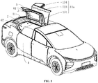
- a vehicle door system in accordance with an embodiment in a first aspect of the present invention is described below with reference to FIG. 1 - FIG. 18 .
- the vehicle door system in the embodiment of the present invention may be mounted to a vehicle body 100 of a vehicle.
- a vehicle door system in an embodiment of the present invention includes a top door 3 and a side door 4.
- the top door 3 opens and closes a first opening (a top doorway 11) of a vehicle body top portion 100b.
- the side door 4 includes a side door body 41 and a side window 42, wherein the side door body 41 opens and closes a second opening 12aa of a side skirt 100a of the vehicle body 100, the side window 42 is mounted on the side door body 41, a top edge and a side edge of the side window 42 are configured to be frameless, when the side door body 41 closes the second opening, the side window 42 can raise and lower relative to the side door body 41, so as to close or open a third opening 12ab of the side skirt 100a of the vehicle body 100, wherein the third opening 12ab is located above the second opening 12aa, the second opening 12aa and the third opening 12ab are interconnected to form a side doorway 12, and the first opening (top doorway 11), the second opening 12aa, and the third opening 12ab are interconnected.
- the top door 3 has a fifth rim 31 connected to the vehicle body top portion 100b, and the top door 3 opens and closes the first opening of the vehicle body top portion 100b with the fifth rim 31 as a rotating shaft;
- the side door body 41 may have a sixth rim 411 connected to the side skirt 100a of the vehicle body 100, and the side door body 41 opens and closes the second opening 12aa on the side of the vehicle body 100 with the sixth rim 411 as a rotating shaft.
- the side window 42 may be provided above the side door body 41, and the side window 42 may raise and lower relative to the side door body 41. By controlling the side window 42 to raise and lower, the third opening 12ab is opened or closed.
- frameless might be understood by those skilled in the art, i.e. an upper half of the side door 4 (opening position of side window 42) is provided in a frameless form, only with vehicle door glass, that is to say, the side window 42 may be separately made of a whole piece of glass and telescopically provided on the side door body 41.
- the top door 3 may be made of glass. In other examples, the top door 3 may also be made of metallic materials or other non-metallic materials, which is not specifically limited in the present invention.
- the top door 3 and the side door body 41 can be opened separately by controlling the side window 42 to raise and lower; besides, in a situation that the side door body 41 closes the second opening 12aa, a vehicle door opening mode in which the third opening 12ab is opened separately or the first opening and the third opening 12ab are opened simultaneously may be realized, thereby making the opening mode of the vehicle door system more flexible, satisfying various use requirements of the driver or the passenger, and obtaining a larger field of view. Further, in a mode in which both the top door 3 and the side door body 41 are opened simultaneously, a space for the driver or the passenger to get on and off may be increased, facilitating entering and exiting the vehicle body 100.
- a top doorway sealing member 131 is provided at a rim of the top doorway 11
- a side doorway sealing member 132 is provided at a rim of the side doorway 12
- the top doorway sealing member 131 and the side doorway sealing member 132 are connected to form a closed ring for sealing an outer rim of a doorway 1.
- a sealing member 133 on a first rim 32 of the top door 3 and the top doorway sealing member 131 and/or a sealing member 134 on a corner window side rim are connected to form a closed ring, and together constitute a seal for the top doorway 11; and the sealing member 133 on the first rim of the top door 3 and the side doorway sealing member 132 and/or the sealing member 134 on the corner window side rim are connected to form a closed ring, and together constitute a seal for the side doorway 12.
- the vehicle body 100 has the doorway 1, and the doorway 1 includes the top doorway 11 and the side doorway 12, wherein the first opening is formed in the top doorway 11, and the second opening 12aa and the third opening 12ab are formed in the side doorway 12.
- the vehicle body 100 includes the side skirt 100a, the vehicle body top portion 100b, and a vehicle body tail portion 100c.
- the top doorway 11 is formed in the vehicle body top portion 100b
- the side doorway 12 is formed in the vehicle body side skirt 100a.
- the side door 4 is connected to an edge of the side doorway 12 so as to open and close the side doorway 12
- the top door 3 is connected to an edge of the top doorway 11 so as to open and close the top doorway 11.
- the top door 3 and the side door 4 may act simultaneously so as to open the top doorway 11 and the side doorway 12 simultaneously, or to close the top doorway 11 and the side doorway 12 simultaneously, or to close one of the top doorway 11 and the side doorway 12 while opening the other.
- the top door 3 and the side door 4 may also act separately, so that in the process that one of the top doorway 11 and the side doorway 12 is opened or closed, the other is maintained in an open or closed state.
- the top door 3 and the side door 4 may act separately, then when the passenger or the driver gets on and off in fine weather, the top door 3 and the side door 4 may be opened simultaneously, thus facilitating the passenger or the driver in getting on and off.
- the side door 4 may be operated so as to open the side door 4 or close the side doorway 12, while the top door 3 is not operated at the same time, so that the top doorway 11 is always in the closed state, further avoiding rain and snow from entering the vehicle body 100 from the top doorway 11 in the open state.
- the top door 3 may also be opened separately so as to realize a skylight function.
- the top door 3 and the side door 4 may act separately, and in cases of rain and snow and water accumulation after rain, a vehicle sensor can be used for detection, and the top door 3 is controlled, by logic built in a vehicle door controller, not to be opened in a corresponding scenario, and only the side door 4 is opened separately.
- This not only can avoid the rain and snow from entering the vehicle body 100 from between edges of the top door 3 and the first opening when the top door 3 closes the first opening, but also can avoid the accumulated water on the top door 3 from entering the vehicle body 100 from between edges of the top door 3 and the first opening in the process of the top door 3 opening the first opening.
- the top door 3 and the side door 4 may act separately, then when carrying out rescue in case that a rollover accident occurs, it is possible to open only the top door 3 or the side door 4, which is not quite restricted by the space or other factors, then rescue is easier to implement.
- the butterfly door, the top cover door, the gull wing door, and the falcon wing door in the related art when being opened and closed, usually perform a turnover movement around a horizontal direction of the vehicle, then the vehicle doors cannot be used for storage.
- a storage space may be provided on the side door 4 to facilitate storage.
- the vehicle body 100 has a central plane that extends in a length direction and a height direction of the vehicle body 100, and the vehicle body 100 is mirror-symmetrical with respect to this central plane as a plane of symmetry. This enables the passenger or the driver to get on and off from two sides of the vehicle body 100, moreover, the symmetrical structure of the vehicle body 100 further facilitates the manufacture of vehicles.
- doorways 1 There may be multiple doorways 1 and they are provided on two sides of the vehicle body 100, respectively. It should be noted that the doorways 1 on the two sides of the vehicle body 100 may be provided in a symmetrical form with respect to the central plane, and also may be provided in a staggered form with respect to the central plane.
- the vehicle body 100 can have a large open space at the vehicle body top portion 100b through the top doorway 11, preferably, there are two side skirts 100a, and the two side skirts 100a are located at two opposite sides of the vehicle body 100, respectively.
- the side doorway 12 includes a first side doorway 12a and a second side doorway that are symmetrically provided, and the second side doorway is provided symmetrically to the first side doorway 12a in a left-right direction of the vehicle body 100.
- the side door 4 includes a first side door 4a and a second side door that are symmetrically provided, and the second side door is provided symmetrically to the first side door in the left-right direction of the vehicle body 100, the first side door 4a is configured to open and close the first side doorway 12a, and the second side door is configured to open and close the second side doorway.
- the top door 3 is connected to a top edge of the first side doorway 12a or a top edge of the second side doorway.
- the first side doorway 12a and the second side doorway are provided on the two side skirts 100a, respectively, and the top doorway 11 extends from a position where one side skirt 100a is located to a position where the other side skirt 100a is located.
- the vehicle body top portion 100b has a portion that is fully opened or nearly fully opened in a width direction of the vehicle, thus the vehicle body top portion 100b has a relatively large open space.
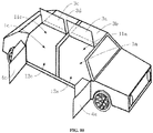
- the doorway 1 includes a first doorway 1a and a second doorway that are symmetrically provided, wherein the first doorway 1a includes a first top doorway 11a and a first side doorway 12a, the second doorway includes a second top doorway and a second side doorway, and the first top doorway 11a and the second top doorway are arranged at an interval.
- the side door 4 includes a first side door 4a and a second side door that are symmetrically provided, wherein the first side door 4a is configured to open and close the first side doorway 12a, and the second side door is configured to open and close the second side doorway.
- the top door 3 includes a first top door 3a and a second top door 3b, the first top door 3a is configured to open or close the first top doorway 11a separately, and the second top door 3b is configured to open or close separately.
- first top doorway 11a and the second top doorway are symmetrically provided on the vehicle body top portion 100b, and the first top doorway 11a and the second top doorway are provided at an interval, wherein the first top doorway 11a is interconnected with the first side doorway 12a, and the second top doorway is interconnected with the second side doorway.
- the first top door 3a may be connected to an edge of the first top doorway 11a away from the first side doorway 12a
- the second top door 3b may be connected to an edge of the second top doorway away from the second side doorway.
- the first top doorway 11a and the second top doorway may be opened and closed separately by controlling the first top door 3a and the second top door 3b.
- the vehicle body 100 has therein both a front row driving space and a rear row passenger space, so that the driver in the front row and the passenger in the rear row can conveniently get into and out of the vehicle body 100, and meanwhile, rain and snow also can be avoided from falling into the vehicle body 100.
- the vehicle door system further includes a first front door 4a' and a second front door, wherein the first front door 4a' is located between a vehicle body head portion and the first side door 4a, and the second front door is located between the vehicle body head portion and the second side door.
- opening directions of the first side door 4a and the first front door 4a' are the same or opposite, and opening directions of the second side door and the second front door are the same or opposite. It may be understood that the first front door 4a' and the second front door are located in the front row driving space, and the first side door 4a and the second side door are located in the rear row passenger space.
- rotating shafts of the first front door 4a' and the second front door rotating relative to the side skirt 100a are respectively located on the side of the first front door 4a' and the side of the second front door adjacent to the vehicle body head portion, and rotating shafts of the first side door 4a and the second side door rotating relative to the side skirt 100a are respectively located on the side of the first side door 4a and the side of the second side door adjacent to the vehicle body head portion, so that the opening directions of the first front door 4a' and the first side door 4a are the same, and the opening directions of the second front door and the second side door are the same.
- the rotating shafts of the first front door 4a' and the second front door rotating relative to the side skirt 100a may be respectively located on the side of the first front door 4a' and the side of the second front door away from the vehicle body head portion, and the rotating shafts of the first side door 4a and the second side door rotating relative to the side skirt 100a are respectively located on the side of the first side door 4a and the side of the second side door away from the vehicle body head portion.
- the rotating shafts of the first front door 4a' and the second front door rotating relative to the side skirt 100a are respectively located on the side of the first front door 4a' and the side of the second front door adjacent to the vehicle body head portion, and the rotating shafts of the first side door 4a and the second side door rotating relative to the side skirt 100a are respectively located on the side of the first side door 4a and the side of the second side door away from the vehicle body head portion, so that the opening directions of the first front door 4a' and the first side door 4a are opposite, and the opening directions of the second front door and the second side door are opposite.
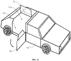
- the doorway 1 includes at least one pair of first doorway 1a and second doorway that are symmetrically provided, the second doorway is provided symmetrically to the first doorway 1a in the left-right direction of the vehicle body 100, and at least one pair of third doorway 1c and fourth doorway that are symmetrically provided, and the fourth doorway is provided symmetrically to the third doorway 1c in the left-right direction of the vehicle body 100.
- the third doorway 1c and the fourth doorway are located between the first doorway 1a and the second doorway and the vehicle body tail portion 100c, the first doorway 1a and the second doorway are interconnected with the front row driving space, and the third doorway 1c and the fourth doorway are interconnected with the rear row passenger space.
- the first doorway 1a has a first top doorway 11a and a first side doorway 12a
- the second doorway includes a second top doorway and a second side doorway
- the third doorway 1c includes a third top doorway 11c and a third side doorway 12c
- the fourth doorway includes a fourth top doorway and a fourth side doorway.
- the top door 3 includes a first top door 3a, a second top door 3b, a third top door 3c, and a fourth top door 3d provided corresponding to the first top doorway 11a, the second top doorway, the third top doorway 11c, and the fourth top doorway, respectively.
- first side doorway 12a and the third side doorway 12c are provided on the side skirt 100a on one side of the vehicle body 100
- second side doorway and the fourth side doorway are provided on the side skirt 100a on the other side of the vehicle body 100.
- the first top door 3a, the second top door 3b, the third top door 3c, and the fourth top door 3d each have a covering surface so as to cover the first top doorway 11a, the second top doorway, the third top doorway 11c, and the fourth top doorway, respectively.
- first top doorway 11a, the second top doorway 11b, the third top doorway 11c, and the fourth top doorway 11d are interconnected, and the first top door 3a, the second top door 3b, the third top door 3c, and the fourth top door 3d are an integral member so as to simultaneously open or close the first top doorway 11a, the second top doorway 11b, the third top doorway 11c, and the fourth top doorway 11d.
- the second top doorway 11b and the second side doorway, and the fourth top doorway 11d and the fourth side doorway are provided at intervals
- the integral member constituted by the first top door 3a, the second top door 3b, the third top door 3c, and the fourth top door 3d is hinged to an edge of the second top doorway 11b adjacent to the second side doorway and an edge of the fourth top doorway 11d adjacent to the fourth side doorway, so that the integral member may simultaneously open or close the first top doorway 11a, the second top doorway 11b, the third top doorway 11c, and the fourth top doorway 11d.
- the first top doorway 11a, the second top doorway, the third top doorway 11c, and the fourth top doorway are provided at intervals.
- the second top doorway is provided symmetrically to the first top doorway 11a in the left-right direction of the vehicle body 100
- the fourth top doorway is provided symmetrically to the third top doorway 11c in the left-right direction of the vehicle body 100.
- the first top door 3a and the third top door 3c are an integral member so as to simultaneously open or close the first top doorway 11a and the third top doorway 11c
- the second top door 3b and the fourth top door 3d are an integral member so as to simultaneously open or close the second top doorway and the fourth top doorway.
- At least one of the first top door 3a and the third top door 3c may be hinged to an edge of the first top doorway 11a away from the first side doorway 12a and/or hinged to an edge of the third top doorway 11c away from the third side doorway 12c
- at least one of the second top door 3b and the fourth top door 3d may be hinged to an edge of the second top doorway away from the second side doorway and/or hinged to an edge of the fourth top doorway away from the fourth side doorway.
- the first top doorway 11a, the second top doorway, the third top doorway 11c, and the fourth top doorway are provided at intervals, and the first top door 3a, the second top door 3b, the third top door 3c, and the fourth top door 3d are separate members to each other.
- the second top doorway is provided symmetrically to the first top doorway 11a in the left-right direction of the vehicle body 100
- the fourth top doorway is provided symmetrically to the third top doorway 11c in the left-right direction of the vehicle body 100.
- the first top door 3a is configured to separately open or close the first top doorway 11a
- the second top door 3b is configured to separately open or close the second top doorway
- the third top door 3c is configured to separately open or close the third top doorway 11c
- the fourth top door 3d is configured to separately open or close the fourth top doorway.
- first top doorway 11a and the first side doorway 12a are interconnected, the second top doorway and the second side doorway are interconnected, the third top doorway 11c and the third side doorway 12c are interconnected, and the fourth top doorway and the fourth side doorway are interconnected.
- the first top door 3a is hinged to an edge of the first top doorway 11a away from the first side doorway 12a
- the second top door 3b is hinged to an edge of the second top doorway away from the second side doorway
- the third top door 3c is hinged to an edge of the third top doorway 11c away from the third side doorway 12c
- fourth top door 3d is hinged to an edge of the fourth top doorway away from the fourth side doorway.
- the side door 4 includes a first side door 4a, a second side door, a third side door 4c, and a fourth side door that are provided corresponding to the first side doorway 12a, the second side doorway, the third side doorway, and the fourth side doorway, respectively, wherein the opening directions of the first side door 4a and the third side door 4c are the same or opposite, and the opening directions of the second side door and the fourth side door are the same or opposite.
- the second side door is provided symmetrically to the first side door 4a in the left-right direction of the vehicle body 100
- the fourth side door is provided symmetrically to the third side door 4c in the left-right direction of the vehicle body 100.
- the opening directions of the first side door 4a and the third side door 4c are the same, and the opening directions of the second side door and the fourth side door are the same.
- the first side door 4a may be hinged to an edge of a side of the first side doorway 12a adjacent to the vehicle body tail portion 100c
- the third side door 4c may be hinged to an edge of a side of the third side doorway 12c adjacent to the vehicle body tail portion 100c
- the second side door may be hinged to an edge of a side of the second side doorway adjacent to the vehicle body tail portion 100c
- the fourth side door may be hinged to an edge of a side of the fourth side doorway adjacent to the vehicle body tail portion 100c.
- the opening directions of the first side door 4a and the third side door 4c are opposite, and the opening directions of the second side door and the fourth side door are opposite.
- the first side door 4a may be hinged to an edge of a side of the first side doorway 12a adjacent to the vehicle body tail portion 100c
- the third side door 4c may be hinged to an edge of a side of the first side doorway 12a away from the vehicle body tail portion 100c
- the second side door may be hinged to an edge of a side of the second side doorway adjacent to the vehicle body tail portion 100c
- the fourth side door may be hinged to an edge of a side of the fourth side doorway away from the vehicle body tail portion 100c.
- a corner window portion 2 (i.e., a fourth opening interconnected with the third opening 12ab) is further formed on the side skirt 100a, and the vehicle door system in an embodiment of the present invention further includes a corner window 5 provided at the corner window portion 2.
- the passenger or the driver may wish to obtain a certain field of view through the corner window 5, and have a relatively wide space for getting on and off, but it is undesired that the corner window portion 2 is opened when the top door 3 opens the top doorway 11.
- the corner window 5 is mounted at the edge of the corner window portion 2, i.e. intersection between the corner window portion 2 and the side skirt 100a, as shown in FIGS. 13 and 14 .
- the corner window is fixed onto the side skirt 100a.
- the corner window 5 has a corner window top rim 52, and the corner window top rim 52 forms a portion of the edge of the top doorway 11. This enables the top doorway 11 to extend in the length direction of the vehicle body 100 to the corner window top rim 52 of the corner window 5, thus increasing the degree to which the top doorway 11 can be opened, and further providing a relatively wide space for the passenger driver to get on and off. Meanwhile, when the top door 3 moves, it is unnecessary for the corner window 5 to move simultaneously, which satisfies the needs of the passenger or the driver, for example, protecting privacy.
- the corner window 5 is movably provided at the fourth opening so as to open and close the fourth opening.
- the top door 3 in order to provide a larger open space for the passenger or the driver to get on and off to facilitate get-on and get-off, and avoid collision, preferably, the top door 3 is hinged to an edge of the top doorway 11, the top door 3 has a fifth rim 31 hinged to the edge of the top doorway 11, and the corner window portion 2 is interconnected with the doorway 1.
- the corner window 5 is mounted on the top door 3 and moves with the top door 3 so as to open and close the corner window portion 2.
- the top door 3 has a first rim 32 adjacent to the top edge of the side window 42, and a second rim 33 extending along the direction of the first rim 32 towards the vehicle body tail portion 100c, the corner window 5 is mounted on the second rim 33, and the corner window 5 can move with the top door 3 so as to open and close the fourth opening (the corner window portion 2) on the side of the vehicle body 100.
- the corner window 5 moves together with the top door 3, so that the top doorway 11 and the corner window portion 2 are opened together, and as the corner window portion 2 and the top doorway 11 are interconnected, when the passenger or the driver gets on or off, the corner window portion 2 may form an avoiding space, thereby avoiding collision with the passenger or the driver.
- the top door 3 is in an arc-shaped plate structure, so that the top door 3 is adapted to the arc-shaped vehicle body top portion 100b, the appearance of the vehicle is more beautiful and softer, avoiding the feeling of abruptness.
- the corner window 5 may be correspondingly provided as a flat plate structure or an arc-shaped plate structure in accordance with the shape of a side wall of the side skirt 100a, so as to ensure aesthetics of the side skirt 100a.
- the corner window 5 is configured to be capable of raising and lowering within the side skirt 100a of the vehicle body, so as to open and close the corner window portion 2.
- the vehicle door system in an embodiment of the present invention further includes a first top door lock assembly 6 connected to the corner window 5.
- the first top door lock assembly 6 includes a first component 61 and a second component 62.
- the first component 61 and the second component 62 are mounted on the corner window 5 and an edge of the corner window portion 2, respectively, so that the first component 61 and the second component 62 can be locked with each other.
- the first component 61 and the top door 3 are indirectly connected by the corner window 5.
- the corner window portion 2 is formed at the side skirt 100a, mounting the second component 62 on the corner window portion 2 enables the second component to be closer to the side of the passenger or the driver, which is more convenient for the passenger or the driver to manually open the top door 3 in an emergency situation.
- the first top door lock assembly 6 may be located in the middle of the vehicle body 100 in the height direction, so that the first top door lock assembly 6 is closer to the position of the passenger or the driver arm, further facilitating operations.
- a sealing member may be used for sealing.
- the corner window 5 has a corner window side rim 51 and a corner window top rim 52, wherein the corner window side rim 51 forms a portion of the edge of the third opening 12ab, the corner window side rim 51 cooperates with the side rim of the side window 42, the top door 3 has the first rim 32 adjacent the top edge of the side window 42, and the second rim 33 extending along the direction of the first rim 32 towards the vehicle body tail portion 100c, and the corner window top rim 52 cooperates with the second rim 33.
- the corner window top rim 52 and/or the second rim 33 is provided with a sealing member. That is to say, the sealing member may be separately provided at the corner window top rim 52, or the sealing member may be separately provided at the second rim 33, or the sealing member may be simultaneously provided at the corner window top rim 52 and the second rim 33.
- a sealing strip is provided on the edge of the doorway 1, and the sealing strip extends in an extending direction of the edge of the doorway 1.
- the top door 3 has a third rim 34, and the third rim 34 cooperates with a front edge of the first opening.
- the vehicle door system further includes a second top door lock assembly 7, wherein the second top door lock assembly 7 includes a third component 71 and a fourth component 72, wherein the third component 71 is mounted at the third rim 34, and the fourth component 72 is mounted at the front edge of the first opening, so that the third component 71 and the fourth component 72 can be locked.
- the top door 3 has a fourth rim 35, the fourth rim 35 cooperates with a rear edge of the first opening, the vehicle door system further includes a third top door lock assembly 10, the third top door lock assembly 10 includes a fifth component 101 and a sixth component 102, the fifth component 101 is mounted at the fourth rim 35, and the sixth component 102 is mounted at the rear edge of the first opening, so that the fifth component and the sixth component can be locked or restrict relative movement between the top door 3 and the vehicle body top portion 10b.
- the top door 3 when closing the top doorway 11, the top door 3 can be locked more firmly with the vehicle body 100, moreover, the second top door lock assembly and the third top door lock assembly are located at two ends of the top door 3 away from each other, respectively, which further improves the firmness of the locking of the top door 3.
- the top door 3 has the fifth rim 31 connected to the vehicle body top portion 100b, and the top door 3 opens and closes the first opening of the vehicle body top portion 100b with the fifth rim 31 as a rotating shaft.
- the side door body 41 has a sixth rim 411 connected to the side skirt 100a of the vehicle body 100, and the side door body 41 opens and closes the second opening 12aa of the side skirt 100a of the vehicle body 100 with the sixth rim 411 as a rotating shaft.
- the vehicle door system 100 further includes a first sliding mechanism 91 and a second sliding mechanism 92, wherein the first sliding mechanism 91 and the second sliding mechanism 92 are both provided between the side skirt 100a and the side door body 41, and the first sliding mechanism 91 and the second sliding mechanism 92 are configured to, in synchronization, drive the side door body 41 to move relative to the side skirt 100a.
- first sliding mechanism and the second sliding mechanism are arranged in a staggered manner in a direction from the vehicle body top portion to the vehicle body bottom portion, and the first sliding mechanism and the second sliding mechanism are arranged in a staggered manner in a direction from the vehicle body head portion to the vehicle body tail portion.
- the first sliding mechanism 91 and the second sliding mechanism 92 are both located below the top door 3, and the first sliding mechanism 91 and the second sliding mechanism 92 are provided at an interval in a front-back direction of the vehicle body 100, and meanwhile, they are provided at an interval in a vertical direction of the vehicle body.
- the vehicle door system in the embodiment of the present invention may save the amount of components, and reduce the costs.
- the first sliding mechanism 91 is located in an upper middle position of the side skirt 100a
- the second sliding mechanism 92 is located in a position close to a bottom portion of the side skirt 100a
- the second sliding mechanism 92 is close to the vehicle head relative to the first sliding mechanism 91.
- the positions of the first sliding mechanism 91 and the second sliding mechanism 92 also may be designed according to practical requirements.
- the first sliding mechanism 91 includes a first guide rail 911, a first hinge mount 912, and a first trolley 913, wherein the first guide rail 911 is provided on the side skirt 100a, the first hinge mount 912 is provided on the side door body 41, the first trolley 913 is provided on the first hinge mount 912, and the first trolley 913 can slide along the first guide rail 911.
- the first trolley 913 can drive the first hinge mount 912 connected thereto to slide along the first guide rail 911, and the first hinge mount 912 can drive the side door body 41 to slide along the first guide rail 911 towards the vehicle body tail portion 100c or the vehicle body head portion, thus the opening or closing of the side door 40 may be realized, with easy and convenient operation.
- the first hinge mount 912 is connected to the first trolley 913 through a pin shaft. All of the first guide rail 911, the first hinge mount 912, and the first trolley 913 may adopt various technical solutions known by those ordinarily skilled in the art now and in the future, and will not be described in detail herein.
- the second sliding mechanism 92 includes a second guide rail 921, a second hinge mount 922, and a second trolley 923, wherein the second guide rail 921 is provided on the side skirt 100a, the second hinge mount 922 is provided on the side door body 41, the second trolley 923 is provided on the second hinge mount 922, and the second trolley 923 can slide along the second guide rail 921.
- the second trolley 923 can drive the second hinge mount 922 connected thereto to slide along the second guide rail 921, and the second hinge mount 922 can drive the side door body 41 to slide along the second guide rail 921 towards the vehicle body tail portion 100c or the vehicle body head portion.
- the opening or closing of the side door 40 may be realized, moreover, the sliding of the side door body 41 relative to the side skirt 100a is more stable.
- the second hinge mount 922 is connected to the second trolley 923 through a pin shaft.
- all of the second guide rail 921, the second hinge mount 922, and the second trolley 923 may adopt various technical solutions known by those ordinarily skilled in the art now and in the future, and will not be described in detail herein.
- the vehicle door system in an embodiment of the present invention further includes a support driving assembly 8, wherein the support driving assembly 8 is connected to the top door 3 at one end, and connected to the vehicle body top portion 100b or the side skirt 100a at the other end, so as to drive the top door 3 to open and close the top doorway 11.
- the support driving assembly 8 are provided opposite relative to the top door 3 and the fifth rim 31, and the support driving assembly 8 may be an electric push rod or a hydraulic push rod, wherein the support driving assembly 8 is hinged to the top door 3 at one end, and hinged to the vehicle body top portion 100b or the side skirt 100a at the other end.
- the support driving assembly 8 may also be axle motors arranged at the fifth rim 31, and the axle motors is connected to a hinge assembly 9 at one end, and connected to the vehicle body top portion 100b at the other end.
- the vehicle door system further includes the hinge assembly 9, and the fifth rim 31 of the top door 3 is hinged to the vehicle body top portion 100b by the hinge assembly 9.
- the top door 3 has the third rim 34 and the fourth rim 35, wherein the third rim 34 cooperates with the front edge of the first opening, and the fourth rim 35 cooperates with the rear edge of the first opening.
- the hinge assembly 9 may be a four-bar assembly. There are two four-bar assemblies and they are located at the third rim 34 and the fourth rim 35 of the top door 3, respectively, and the top door 3 is hinged to the vehicle body top portion 100b by two four-bar assemblies.
- the hinge assembly 9 may also adopt various structures known to those ordinarily skilled in the art now and in the future, for example, hinges in slide-in or snap-in and other structures may be adopted, which will not be described in detail herein.
- the vehicle door system further includes an obstacle detector and a vehicle door controller.
- the obstacle detector may be provided on any one of the top door 3, the side door 4, and the vehicle body 100, and configured to detect whether there is an obstacle in the opening and closing stroke of the top door 3 and/or the side door 4.
- the vehicle door controller is provided on any one of the top door 3, the side door 4, and the vehicle body 100, and is configured to control the movement of at least one of the side door body 41, the side window 42, and the top door 3.
- the vehicle door controller is configured to detect whether a door opening request is received; detect, in case that the door opening request is received, whether a distance between the top edge of the side window and the top edge of the side door body reaches a predetermined distance; and send, in case that the predetermined distance is reached, an opening signal, so as to control the top door and/or the side door body to be opened.
- the vehicle door controller further may execute a control method as follows.
- a control method of a vehicle door system in accordance with an embodiment in a second aspect of the present invention is described below with reference to FIG. 19 - FIG. 25 .
- control method of a vehicle door system in accordance with an embodiment of the present invention includes:
- the side window 42 is mounted above the side door body 41, and the side window 42 may raise and lower relative to the side door body 41.
- the top edge of the side window 42 cooperates with the first rim 32 of the top door 3, at this time, the distance between the top edge of the side window 42 and the first rim 32 of the top door 3 is minimal, and at this time, the top door 3 or the side door body 41 cannot be directly opened.
- the side window 42 When the side window 42 is lowered to such a degree that the distance from the top edge of the side window 42 to the first rim 32 of the top door 3 is a first predetermined distance, that is, when the top edge of the side window 42 reaches a position A, the top edge of the side window 42 and the first rim 32 of the top door 3 are disengaged from each other, at this time, the side door body 41 may be directly opened.
- the controller may receive the opening signal, and send the signal to drive the support driving assembly to act so as to open the top door 3.
- the control method in an embodiment of the present invention by detecting whether the distance between the top edge of the side window 42 and the first rim 32 of the top door 3 reaches the predetermined distance, it may be judged whether the top edge of the side window 42 and the first rim 32 of the top door 3 are disengaged, and when the top edge of the side window 42 is located at the position A, that is, the predetermined distance is reached, the side door body 41 may be opened, thereby facilitating the driver or the passenger to get on and off.
- the door opening request includes a first door opening request
- step S102 detecting whether the distance between the top edge of the side window 42 and the first rim 32 of the top door 3 reaches the predetermined distance
- step S103 sending an opening signal further includes:
- the side door 4 is provided with a pushing mechanism for controlling the side window 42 to raise and lower, and in response to the first lowering signal, the pushing mechanism starts and drives the side window 42 to be lowered.
- the pushing mechanism stops so that the side window 42 remains in a current position.
- the door opening request includes a second door opening request
- step S102 detecting whether the distance between the top edge of the side window 42 and the first rim 32 of the top door 3 reaches the predetermined distance
- the top door 3 may be controlled to be opened separately, and the side door body 41 will not interfere with the opening of the top door 3.
- step S303 sending a second lowering signal, wherein the first lowering signal is configured to control the side window 42 to be lowered, so that the distance between the top edge of the side window 42 and the first rim 32 of the top door 3 reaches the second predetermined distance.
- step S302 sending the second opening signal further includes:
- the second opening signal may be sent so as to control the top door 3 to be directly opened; in case that it is detected that the side door body 41 is not opened by the first predetermined angle, in order to avoid the side window 42 from interfering with the opening of the top door 3, it is necessary to send the second lowering signal to control the side window 42 to be lowered, so that the distance between the top edge of the side window 42 and the first rim 32 of the top door 3 reaches the second predetermined distance.
- step S302 sending the second opening signal further includes:
- the top door 3 in case that the distance between the corner window top rim 52 and the edge of the fourth opening does not reach the lowering distance of the corner window, the top door 3 will interfere with the corner window 5 in the opening process, and therefore the top door 3 cannot be opened under this condition.
- step S302 sending the second opening signal further includes:
- step S302 sending the second opening signal so as to control the top door 3 to be opened.
- control method further includes:
- the obstacle detector detects that there is an obstacle in the vicinity of the top door 3 or the side door body 41, it may be realized that the top door 3 or the side door body 41 is controlled to stop opening, thereby avoiding the top door 3 or the side door body 41 from touching the obstacle in the opening stroke, so as to improve the safety of the vehicle door system.
- FIG. 25 shows a specific example of the control method.
- a rear door linked door opening request i.e., door opening request
- the obstacle detector determines whether there is an obstacle in the vicinity of the rear door (i.e., side door body 41), and in case that there is an obstacle, the stop signal is sent to control the rear door to stop opening.
- the side window (i.e., side window 42) of the rear door is controlled to be lowered, and it is detected whether the top edge of the side window is lowered to the position A, wherein in case that the top edge of the side window is lowered to the position A, the distance between the top edge of the side window and the first rim 32 of the top door 3 is the first predetermined distance.
- the first opening signal is then sent to control the rear door to be opened, and it is detected by the obstacle detector whether there is an obstacle in the vicinity of the rear door or whether there is a dangerous object approaching the rear door in the opening process of the rear door.
- the stop signal sent by the obstacle detector is not received, it is detected whether the rear door moves into position; and in case that the stop signal sent by the obstacle detector is received, the rear door is controlled to stop opening.
- an angle by which the rear door is opened is greater than X (i.e., the first predetermined angle). In case that it is greater than X, the top door 3 is controlled to be opened. In case that it is not greater than X, the side window of the rear door is controlled to continue to be lowered from the position A. It is detected whether the top rim of the side window is lowered to a position B, wherein the height of the position B is lower than the height of the position A. In case that the top rim of the side window is lowered to the position B, the distance between the top edge of the side window and the first rim 32 of the top door 3 is the second predetermined distance, and the second opening signal is sent to control the top door 3 to be opened.
- X i.e., the first predetermined angle
- the stop signal is sent to control the top door 3 to stop opening.
- the stop signal is sent to control the top door 3 to stop opening.
- control method in accordance with an embodiment in a third aspect of the present invention is described below with reference to FIG. 26 - FIG. 29 .
- control method of a vehicle door system in an embodiment of the present invention includes:
- the distance between the top rim of the side window 42 and the first rim 32 of the top door 3 is greater than or equal to the predetermined distance, the relative movement between the side window 42 and the top door 3 will not interfere, thus it may be ensured that the top door 3 and/or the side door body 41 may be smoothly closed.
- control method further includes:
- control method further includes:
- control method further includes:
- the obstacle detector detects that there is an obstacle in the vicinity of the top door 3 or the side door body 41, it may be realized that the top door 3 or the side door body 41 is controlled to stop closing, thereby avoiding the top door 3 or the side door body 41 from touching the obstacle during the closing stroke, so as to improve the safety of the vehicle door system.
- control method A specific example of the control method is described below with reference to FIG. 29 .
- a rear door linked door closing request is received, and if so, it is detected whether the distance between the top rim of the side window 42 and the first rim 32 of the top door 3 is greater than B (i.e., second predetermined distance).
- B i.e., second predetermined distance
- the lowering signal is sent, wherein the lowering signal is configured to control the side window 42 to be lowered, so that the distance between the top rim of the side window 42 and the first rim 32 of the top door 3 is greater than B.
- a closing signal is sent, wherein the closing signal is configured to control the top door 3 and/or the side door body 41 to be closed.
- the stop signal is sent so as to control the side door 4 to stop closing. In case that there is no obstacle, it is detected whether the side door 4 moves into position.
- the stop signal is sent so as to control the top door 3 to stop closing. In case that there is no obstacle, it is detected whether the top door 3 moves into position.
- the side window 42 is controlled to stay in a current position.
- the raising signal is sent so as to raise the side window 42 until the side window 42 raises to a position to close the third opening 12ab. So far, the door closing is completed.
- a vehicle in accordance with an embodiment in a fourth aspect of the present invention includes the vehicle door system in accordance with an embodiment in the first aspect of the present invention.
- Other configurations of the vehicle in the present embodiment such as a vehicle frame, a chassis, and a rear suspension apparatus, may adopt various technical solutions known to those ordinarily skilled in the art now and in the future, and are not described in detail herein.
Landscapes
- Engineering & Computer Science (AREA)
- Mechanical Engineering (AREA)
- Power-Operated Mechanisms For Wings (AREA)
- Lock And Its Accessories (AREA)
- Specific Sealing Or Ventilating Devices For Doors And Windows (AREA)
Abstract
Description
- The present application claims the priority to the Chinese patent application filed with the Chinese Patent Office on July 31, 2019 with the filing No.
2019106975671 201811470299.1 - The Chinese patent application with the filing No.
2019106975671 201811070063.9 2018110700632.X 2019106975671 - The present invention relates to the technical field of vehicle, in particular to a vehicle door system and a control method thereof, and a vehicle having the same.
- The vehicle has become an indispensable means of transportation for human beings, and from the tendency of passenger vehicle modeling, making the vehicle body low is beneficial to reducing the wind resistance and increasing the stability, but will cause inconvenience for the passenger to get in and out of the vehicle. Taking a supercar with a low vehicle body as an example, all manufacturers are exploring novel ways to open the door so as to solve the above problem. For vehicles having a butterfly door, a top cover door, a gull wing door, and a falcon wing door in the related art, as the top structure and the side structure of the doors are connected, the top portion and the side portion are required to be opened at the same time to realize opening of the vehicle door, then when the vehicle door is opened in rain and snow, rain and snow will easily enter the vehicle body from the opened top portion. Further, water often accumulates on a top door, then when the top door is started to open a first opening after rain and snow, the accumulated water usually will enter the vehicle body from positions of edges of the top door and the first opening, thus causing contamination to the inside of the vehicle body.
- In order to solve one or more technical problems in the prior art, the present invention provides a vehicle door system and a control method thereof and a vehicle having the same.
- In a first aspect, an embodiment of the present invention provides a vehicle door system, including: a top door, the top door opening and closing a first opening of a vehicle body top portion; and a side door, the side door including a side door body and a side window, wherein the side door body opens and closes a second opening of a vehicle body side skirt, the side window is mounted on the side door body, both a top edge and a side edge of the side window are configured to be frameless, and the side window is capable of raising or lowering relative to the side door body; when the side door body closes the second opening, the side window raises or lowers to open or close a third opening of the vehicle body side skirt, wherein the third opening is located above the second opening, and the first opening, the second opening, and the third opening are interconnected.
- In an embodiment, the top door has a first rim cooperating with a top edge of the side window, and the first rim is mounted with a sealing member.
- In an embodiment, the vehicle body has a doorway, and the doorway includes a top doorway and a side doorway, and wherein the first opening is formed in the top doorway, and the second opening and the third opening are formed in the side doorway.
- In an embodiment, the side doorway includes a first side doorway and a second side doorway that are symmetrically provided; the side door includes a first side door and a second side door that are symmetrically provided, wherein the first side door is configured to open and close the first side doorway, and the second side door is configured to open and close the second side doorway; and the top door is connected to a top edge of the first side doorway or a top edge of the second side doorway.
- In an embodiment, the doorway includes a first doorway and a second doorway that are symmetrically provided, the first doorway includes a first top doorway and a first side doorway, the second doorway includes a second top doorway and a second side doorway, and the first top doorway and the second top doorway are arranged at an interval; the side door includes a first side door and a second side door that are symmetrically provided, the first side door is configured to open and close the first side doorway, and the second side door is configured to open and close the second side doorway; and the top door includes a first top door and a second top door, the first top door is configured to open or close the first top doorway separately, and the second top door is configured to open or close the second top doorway separately.
- In an embodiment, the vehicle door system further includes a first front door and a second front door, wherein the first front door is located between a vehicle body head portion and the first side door, and the second front door is located between the vehicle body head portion and the second side door, and wherein opening directions of the first side door and the first front door are the same or opposite, and opening directions of the second side door and the second front door are the same or opposite.
- In an embodiment, the doorway includes at least one pair of first doorway and second doorway that are symmetrically provided, and at least one pair of third doorway and fourth doorway that are symmetrically provided, the first doorway includes a first top doorway and a first side doorway, the second doorway includes a second top doorway and a second side doorway, the third doorway includes a third top doorway and a third side doorway, and the fourth doorway includes a fourth top doorway and a fourth side doorway; and the top door includes a first top door, a second top door, a third top door, and a fourth top door provided corresponding to the first top doorway, the second top doorway, the third top doorway, and the fourth top doorway, respectively.
- In an embodiment, the first top doorway, the second top doorway, the third top doorway, and the fourth top doorway are interconnected, and the first top door, the second top door, the third top door, and the fourth top door are an integral member so as to simultaneously open or close the first top doorway, the second top doorway, the third top doorway, and the fourth top doorway.
- In an embodiment, the first top doorway, the second top doorway, the third top doorway, and the fourth top doorway are provided at intervals; and the first top door and the third top door are an integral member so as to simultaneously open or close the first top doorway and the third top doorway, and the second top door and the fourth top door are an integral member so as to simultaneously open or close the second top doorway and the fourth top doorway.
- In an embodiment, the first top doorway, the second top doorway, the third top doorway, and the fourth top doorway are provided at intervals; and the first top door, the second top door, the third top door, and the fourth top door are separate members to each other, wherein the first top door is configured to separately open or close the first top doorway, the second top door is configured to separately open or close the second top doorway, the third top door is configured to separately open or close the third top doorway, and the fourth top door is configured to separately open or close the fourth top doorway.
- In an embodiment, the side door includes a first side door, a second side door, a third side door, and a fourth side door that are provided corresponding to the first side doorway, the second side doorway, the third side doorway, and the fourth side doorway, respectively; and wherein opening directions of the first side door and the third side door are the same or opposite, and opening directions of the second side door and the fourth side door are the same or opposite.
- In an embodiment, the vehicle body side skirt has a fourth opening interconnected with the third opening, and the vehicle door system further includes a corner window provided at the fourth opening.
- In an embodiment, the corner window is fixed at the fourth opening.
- In an embodiment, the corner window is movably provided at the fourth opening so as to open and close the fourth opening.
- In an embodiment, the top door has a first rim adjacent to the top edge of the side window, and a second rim extending along a direction of the first rim towards a vehicle body tail portion, the corner window is mounted on the second rim, and the corner window is capable of moving along with the top door so as to open and close the fourth opening.
- In an embodiment, a sealing member is provided between a corner window side rim and a side edge of the side window.
- In an embodiment, the vehicle door system further includes a first top door lock assembly, wherein the first top door lock assembly includes a first component and a second component, the first component is mounted on the corner window, and the second component is mounted at an edge of the fourth opening, so that the first component and the second component are capable of being locked.
- In an embodiment, the corner window is mounted at an edge of the fourth opening, and the corner window is capable of raising and lowering relative to the edge of the fourth opening.
- In an embodiment, the corner window has a corner window side rim and a corner window top rim, the corner window side rim forms a portion of an edge of the third opening, the corner window side rim cooperates with a side rim of the side window, the top door has a first rim adjacent the top edge of the side window, and a second rim extending along a direction of the first rim towards a vehicle body tail portion, and the corner window top rim cooperates with the second rim; and wherein at least one of the corner window side rim, the corner window top rim, and the second rim is provided with a sealing member.
- In an embodiment, the top door has a third rim, the third rim cooperates with a front edge of the first opening, the vehicle door system further includes a second top door lock assembly, the second top door lock assembly includes a third component and a fourth component, the third component is mounted at the third rim, and the fourth component is mounted at the front edge of the first opening, so that the third component and the fourth component are capable of being locked.
- In an embodiment, the top door has a fourth rim, the fourth rim cooperates with a rear edge of the first opening, the vehicle door system further includes a third top door lock assembly, the third top door lock assembly includes a fifth component and a sixth component, the fifth component is mounted at the fourth rim, and the sixth component is mounted at the rear edge of the first opening, so that the fifth component and the sixth component are capable of being locked or restricting relative movement between the top door and the vehicle body top portion.
- In an embodiment, the top door has a fifth rim connected to the vehicle body top portion, and the top door opens and closes the first opening of the vehicle body top portion with the fifth rim as a rotating shaft; the side door body has a sixth rim connected to the vehicle body side skirt, and the side door body opens and closes the second opening in the vehicle body side skirt with the sixth rim as a rotating shaft.
- In an embodiment, the vehicle door system further includes a first sliding mechanism and a second sliding mechanism, wherein the first sliding mechanism and the second sliding mechanism are both provided between the vehicle body side skirt and the side door body, and the first sliding mechanism and the second sliding mechanism are configured to, in synchronization, drive the side door body to move relative to the vehicle body side skirt.
- In an embodiment, the first sliding mechanism and the second sliding mechanism are arranged in a staggered manner in a direction from the vehicle body top portion to the vehicle body bottom portion, and the first sliding mechanism and the second sliding mechanism are arranged in a staggered manner in a direction from the vehicle body head portion to the vehicle body tail portion.
- In an embodiment, the first sliding mechanism includes a first guide rail, a first hinge mount, and a first trolley, and wherein the first guide rail is provided on the vehicle body side skirt, the first hinge mount is provided on the side door body, the first trolley is provided on the first hinge mount, and the first trolley is capable of sliding along the first guide rail.
- In an embodiment, the second sliding mechanism includes a second guide rail, a second hinge mount, and a second trolley, and wherein the second guide rail is provided on the vehicle body side skirt, the second hinge mount is provided on the side door body, the second trolley is provided on the second hinge mount, and the second trolley is capable of sliding along the second guide rail.
- In an embodiment, the vehicle door system of any one of
claims 1 to 26, further including a support driving assembly, wherein the support driving assembly is connected to the top door at one end, and connected to the vehicle body top portion or the side skirt at other end, so as to drive the top door to open and close the first opening. - In an embodiment, the vehicle door system further includes a hinge assembly, wherein the top door has a fifth rim connected to the vehicle body top portion, and the fifth rim of the top door is hinged to the vehicle body top portion by the hinge assembly.
- In an embodiment, the top door has a third rim and a fourth rim, wherein the third rim cooperates with a front edge of the first opening, the fourth rim cooperates with a rear edge of the first opening, the hinge assembly is a four-bar assembly, the four-bar assembly is arranged at the third rim and the fourth rim of the top door, and the top door is hinged to the vehicle body top portion by the four-bar assembly.
- In an embodiment, the vehicle door system further includes a sealing member, wherein the sealing member includes a top doorway sealing member and a side doorway sealing member, the top doorway sealing member is provided at the rim of the top doorway, and the side doorway sealing member is provided at the rim of the side doorway.
- In an embodiment, the vehicle door system further includes an obstacle detector and a vehicle door controller, wherein the obstacle detector is provided on any one of the top door, the side door, and the vehicle body, and configured to detect whether there is an obstacle in an opening and closing stroke of the top door and/or the side door; and the vehicle door controller is provided on any one of the top door, the side door, and the vehicle body, and is configured to control movement of at least one of the side door, the top door, and the side window.
- In a second aspect, an embodiment of the present invention provides control method of a vehicle door system, including:
- detecting whether a door opening request is received, wherein the door opening request is configured to request a top door and/or a side door body to be opened;
- detecting, in case that the door opening request is received, whether a distance between a top edge of a side window and a first rim of the top door reaches a predetermined distance; and
- sending, in case that the predetermined distance is reached, an opening signal, wherein the opening signal is configured to control the top door and/or the side door body to be opened.
- In an embodiment, the detecting, in case that the door opening request is received, whether the distance between the top edge of the side window and the first rim of the top door reaches the predetermined distance, includes:
- detecting, in case that a first door opening request is received, whether the distance between the top edge of the side window and the first rim of the top door reaches a first predetermined distance, wherein the first door opening request is configured to request the side door body to be opened; and
- the sending, in case that the predetermined distance is reached, an opening signal, includes:
sending, in case that the first predetermined distance is reached, a first opening signal, wherein the first opening signal is configured to control the side door body to be opened. - In an embodiment, the sending, in case that the predetermined distance is reached, the opening signal, further includes:
sending, in case that the first predetermined distance is not reached, a first lowering signal, wherein the first lowering signal is configured to control the side window to be lowered, so that the distance between the top edge of the side window and the first rim of the top door reaches the first predetermined distance. - In an embodiment, the detecting, in case that the door opening request is received, whether the distance between the top edge of the side window and the first rim of the top door reaches the predetermined distance, includes:
- detecting, in case that a second door opening request is received, whether the distance between the top edge of the side window and the first rim of the top door reaches a second predetermined distance, wherein the second door opening request is configured to request the top door to be opened, and the second predetermined distance is greater than the first predetermined distance; and
- the sending, in case that the predetermined distance is reached, the opening signal, includes:
sending, in case that the second predetermined distance is reached, a second opening signal, wherein the second opening signal is configured to control the top door to be opened. - In an embodiment, the sending, in case that the predetermined distance is reached, the opening signal, further includes:
- detecting, in case that the second predetermined distance is not reached, whether the side door body is opened by a first predetermined angle; and
- sending, in case that the side door body is opened by the first predetermined angle, the second opening signal.
- In an embodiment, the method further includes:
sending, in case that the side door body is not opened by the first predetermined angle, a second lowering signal, wherein the second lowering signal is configured to control the side window to be lowered, so that the distance between the top edge of the side window and the first rim of the top door reaches the second predetermined distance. - In an embodiment, the method further includes:
- detecting, in case that the second predetermined distance is reached, whether the distance between a corner window top rim and an edge of a fourth opening reaches a predetermined lowering distance of the corner window; and
- sending, in case that the lowering distance of the corner window is reached, the second opening signal.
- In an embodiment, the method further includes:
sending, in case that the lowering distance of the corner window is not reached, a corner window lowering signal, wherein the corner window lowering signal is configured to control the corner window to be lowered, so that the distance between the corner window top rim and the edge of the fourth opening reaches the lowering distance of the corner window. - In an embodiment, the method further includes:
- detecting whether an early warning signal sent by an obstacle detector is received, wherein the early warning signal is configured to prompt that there is an obstacle in an opening stroke of the top door and/or the side door body; and
- sending, in case that the early warning signal is received, a stop signal, wherein the stop signal is configured to control the top door and/or the side door body to stop opening.
- In a third aspect, an embodiment of the present invention provides a control method of a vehicle door system, including:
- detecting whether a door closing request is received, wherein the door closing request is configured to request a top door and/or a side door body to be closed;
- detecting, in case that the door closing request is received, whether a distance between an top edge of a side window and a first rim of the top door reaches a predetermined distance; and
- sending, in case that the predetermined distance is reached, a closing signal, wherein the closing signal is configured to control the top door and/or the side door body to be closed.
- In an embodiment, the method further includes:
sending, in case that the predetermined distance is not reached, a lowering signal, wherein the lowering signal is configured to control the side window to be lowered, so that the distance between the top edge of the side window and the first rim of the top door reaches the predetermined distance. - In an embodiment, the method further includes:
- detecting whether the side door body and the top door are closed in place; and
- sending, in case that the side door body and the top door are closed in place, a side window raising signal, wherein the side window raising signal is configured to control the side window to raise.
- In an embodiment, the method further includes:
- detecting whether an early warning signal sent by an obstacle detector is received, wherein the early warning signal is configured to prompt that there is an obstacle in a closing stroke of the top door and/or the side door body; and
- sending, in case that the early warning signal is received, a stop signal, wherein the stop signal is configured to control the top door and/or the side door body to stop closing.
- In a fourth aspect, an embodiment of the present invention provides a vehicle, including the vehicle door system according to the first aspect of the present invention.
- All the above technical solutions have the following advantages or beneficial effects: the convenience for the passenger or the driver to get on and off may be improved while satisfying the design of making the vehicle body low.
-
-
FIG. 1 is a structural schematic view of a vehicle door system in accordance with an embodiment of the present invention; -
FIG. 2 is a structural schematic view of the vehicle door system in accordance with an embodiment of the present invention; -
FIG. 3 is a structural schematic view of the vehicle door system in accordance with an embodiment of the present invention; -
FIG. 4 is a structural schematic view of the vehicle door system in accordance with an embodiment of the present invention; -
FIG. 5 is a structural schematic view of the vehicle door system in accordance with an embodiment of the present invention; -
FIG. 6 is a structural schematic view of the vehicle door system in accordance with an embodiment of the present invention; -
FIG. 7 is a structural schematic view of the vehicle door system in accordance with an embodiment of the present invention; -
FIG. 8 is a structural schematic view of the vehicle door system in accordance with an embodiment of the present invention; -
FIG. 9 is a structural schematic view of the vehicle door system in accordance with an embodiment of the present invention; -
FIG. 10 is a structural schematic view of the vehicle door system in accordance with an embodiment of the present invention; -
FIG. 11 is a structural schematic view of the vehicle door system in accordance with an embodiment of the present invention; -
FIG. 12A is a structural schematic view of the vehicle door system in accordance with an embodiment of the present invention; -
FIG. 12B is a structural schematic view of the vehicle door system in accordance with an embodiment of the present invention; -
FIG. 13 is a structural schematic view of the vehicle door system in accordance with an embodiment of the present invention; -
FIG. 14 is a structural schematic view of the vehicle door system in accordance with an embodiment of the present invention; -
FIG. 15 is a structural schematic view of the vehicle door system in accordance with an embodiment of the present invention; -
FIG. 16A is a structural schematic view of the vehicle door system in accordance with an embodiment of the present invention; -
FIG. 16B is a structural schematic view of the vehicle door system in accordance with an embodiment of the present invention; -
FIG. 17 is a structural schematic view of the vehicle door system in accordance with an embodiment of the present invention; -
FIG. 18 is a structural schematic view of the vehicle door system in accordance with an embodiment of the present invention; -
FIG. 19 is a flow chart of a control method of the vehicle door system in accordance with an embodiment of the present invention; -
FIG. 20 is a flow chart of the control method of the vehicle door system in accordance with an embodiment of the present invention; -
FIG. 21 is a flow chart of the control method of the vehicle door system in accordance with an embodiment of the present invention; -
FIG. 22 is a flow chart of the control method of the vehicle door system in accordance with an embodiment of the present invention; -
FIG. 23 is a flow chart of the control method of the vehicle door system in accordance with an embodiment of the present invention; -
FIG. 24 is a flow chart of the control method of the vehicle door system in accordance with an embodiment of the present invention; -
FIG. 25 is a flow chart of the control method of the vehicle door system in accordance with an embodiment of the present invention; -
FIG. 26 is a flow chart of the control method of the vehicle door system in accordance with an embodiment of the present invention; -
FIG. 27 is a flow chart of the control method of the vehicle door system in accordance with an embodiment of the present invention; -
FIG. 28 is a flow chart of the control method of the vehicle door system in accordance with an embodiment of the present invention; and -
FIG. 29 is a flow chart of the control method of the vehicle door system in accordance with an embodiment of the present invention. - A vehicle door system in accordance with an embodiment in a first aspect of the present invention is described below with reference to
FIG. 1 - FIG. 18 . The vehicle door system in the embodiment of the present invention may be mounted to avehicle body 100 of a vehicle. - As shown in
FIG. 1 - FIG. 18 , a vehicle door system in an embodiment of the present invention includes atop door 3 and aside door 4. - Specifically, the
top door 3 opens and closes a first opening (a top doorway 11) of a vehiclebody top portion 100b. Theside door 4 includes aside door body 41 and aside window 42, wherein theside door body 41 opens and closes a second opening 12aa of aside skirt 100a of thevehicle body 100, theside window 42 is mounted on theside door body 41, a top edge and a side edge of theside window 42 are configured to be frameless, when theside door body 41 closes the second opening, theside window 42 can raise and lower relative to theside door body 41, so as to close or open a third opening 12ab of theside skirt 100a of thevehicle body 100, wherein the third opening 12ab is located above the second opening 12aa, the second opening 12aa and the third opening 12ab are interconnected to form aside doorway 12, and the first opening (top doorway 11), the second opening 12aa, and the third opening 12ab are interconnected. - Besides, the
top door 3 has afifth rim 31 connected to the vehiclebody top portion 100b, and thetop door 3 opens and closes the first opening of the vehiclebody top portion 100b with thefifth rim 31 as a rotating shaft; theside door body 41 may have asixth rim 411 connected to theside skirt 100a of thevehicle body 100, and theside door body 41 opens and closes the second opening 12aa on the side of thevehicle body 100 with thesixth rim 411 as a rotating shaft. - It may be understood that the
side window 42 may be provided above theside door body 41, and theside window 42 may raise and lower relative to theside door body 41. By controlling theside window 42 to raise and lower, the third opening 12ab is opened or closed. It should be noted that, "frameless" might be understood by those skilled in the art, i.e. an upper half of the side door 4 (opening position of side window 42) is provided in a frameless form, only with vehicle door glass, that is to say, theside window 42 may be separately made of a whole piece of glass and telescopically provided on theside door body 41. - In one example, the
top door 3 may be made of glass. In other examples, thetop door 3 may also be made of metallic materials or other non-metallic materials, which is not specifically limited in the present invention. - According to the vehicle door system in the embodiment of the present invention, by configuring the top edge and the side edge of the
side window 42 as frameless structures, thetop door 3 and theside door body 41 can be opened separately by controlling theside window 42 to raise and lower; besides, in a situation that theside door body 41 closes the second opening 12aa, a vehicle door opening mode in which the third opening 12ab is opened separately or the first opening and the third opening 12ab are opened simultaneously may be realized, thereby making the opening mode of the vehicle door system more flexible, satisfying various use requirements of the driver or the passenger, and obtaining a larger field of view. Further, in a mode in which both thetop door 3 and theside door body 41 are opened simultaneously, a space for the driver or the passenger to get on and off may be increased, facilitating entering and exiting thevehicle body 100. - For the vehicle in the related art, water easily enters the vehicle body from positions of door slits when it rains or cleaning the vehicle. Since the vehicle door and the doorway are divided into different parts, it is difficult to make the vehicle door waterproof.
- In order to avoid this problem, as shown in
FIG. 5 , in the vehicle door system of an embodiment of the present invention, a topdoorway sealing member 131 is provided at a rim of thetop doorway 11, a sidedoorway sealing member 132 is provided at a rim of theside doorway 12, and the topdoorway sealing member 131 and the sidedoorway sealing member 132 are connected to form a closed ring for sealing an outer rim of adoorway 1. When thetop door 3 is closed, a sealingmember 133 on afirst rim 32 of thetop door 3 and the topdoorway sealing member 131 and/or a sealingmember 134 on a corner window side rim are connected to form a closed ring, and together constitute a seal for thetop doorway 11; and the sealingmember 133 on the first rim of thetop door 3 and the sidedoorway sealing member 132 and/or the sealingmember 134 on the corner window side rim are connected to form a closed ring, and together constitute a seal for theside doorway 12. - In an embodiment, as shown in
FIG. 4 , thevehicle body 100 has thedoorway 1, and thedoorway 1 includes thetop doorway 11 and theside doorway 12, wherein the first opening is formed in thetop doorway 11, and the second opening 12aa and the third opening 12ab are formed in theside doorway 12. - Specifically, the
vehicle body 100 includes theside skirt 100a, the vehiclebody top portion 100b, and a vehiclebody tail portion 100c. Thetop doorway 11 is formed in the vehiclebody top portion 100b, and theside doorway 12 is formed in the vehiclebody side skirt 100a. Theside door 4 is connected to an edge of theside doorway 12 so as to open and close theside doorway 12, and thetop door 3 is connected to an edge of thetop doorway 11 so as to open and close thetop doorway 11. - In use, the
top door 3 and theside door 4 may act simultaneously so as to open thetop doorway 11 and theside doorway 12 simultaneously, or to close thetop doorway 11 and theside doorway 12 simultaneously, or to close one of thetop doorway 11 and theside doorway 12 while opening the other. Thetop door 3 and theside door 4 may also act separately, so that in the process that one of thetop doorway 11 and theside doorway 12 is opened or closed, the other is maintained in an open or closed state. - Further, the
top door 3 and theside door 4 may act separately, then when the passenger or the driver gets on and off in fine weather, thetop door 3 and theside door 4 may be opened simultaneously, thus facilitating the passenger or the driver in getting on and off. When the passenger or the driver gets on and off in rain or snow, only theside door 4 may be operated so as to open theside door 4 or close theside doorway 12, while thetop door 3 is not operated at the same time, so that thetop doorway 11 is always in the closed state, further avoiding rain and snow from entering thevehicle body 100 from thetop doorway 11 in the open state. Besides, thetop door 3 may also be opened separately so as to realize a skylight function. - It should be noted that for vehicles having the butterfly door, the top cover door, the gull wing door, and the falcon wing door in the related art, as the top structure and the side structure of the doors are connected, the top portion and the side portion are required to be opened simultaneously to realize opening of the vehicle door, then when the vehicle door is opened in rain and snow, rain and snow will enter the vehicle body from the opened top portion. Further, water often accumulates on the top door of the vehicles in the related art, then when the top door is started to open the first opening after rain and snow, the accumulated water usually will enter the vehicle body from positions of edges of the top door and the first opening, thus causing contamination to the inside of the vehicle body.
- However, according to the vehicle door system in an embodiment of the present invention, the
top door 3 and theside door 4 may act separately, and in cases of rain and snow and water accumulation after rain, a vehicle sensor can be used for detection, and thetop door 3 is controlled, by logic built in a vehicle door controller, not to be opened in a corresponding scenario, and only theside door 4 is opened separately. This not only can avoid the rain and snow from entering thevehicle body 100 from between edges of thetop door 3 and the first opening when thetop door 3 closes the first opening, but also can avoid the accumulated water on thetop door 3 from entering thevehicle body 100 from between edges of thetop door 3 and the first opening in the process of thetop door 3 opening the first opening. - It should be noted that for vehicles having the butterfly door, the top cover door, the gull wing door, and the falcon wing door in the related art, as the top structure and the side structure of the doors are connected, the top portion and the side portion are required to be opened simultaneously to realize opening of the vehicle door, therefore, after occurrence of rollover accidents, the vehicle door is hardly opened completely as the vehicle top part is pressed or due to other reasons, then it is hard to carry out rescue. However, according to the vehicle door system in the embodiment of the present invention, the
top door 3 and theside door 4 may act separately, then when carrying out rescue in case that a rollover accident occurs, it is possible to open only thetop door 3 or theside door 4, which is not quite restricted by the space or other factors, then rescue is easier to implement. - Moreover, the butterfly door, the top cover door, the gull wing door, and the falcon wing door in the related art, when being opened and closed, usually perform a turnover movement around a horizontal direction of the vehicle, then the vehicle doors cannot be used for storage. However, in the present embodiment, as the
top door 3 and theside door 4 are provided separately, a storage space may be provided on theside door 4 to facilitate storage. - In some embodiments, as shown in
FIG. 1 - FIG. 16 , thevehicle body 100 has a central plane that extends in a length direction and a height direction of thevehicle body 100, and thevehicle body 100 is mirror-symmetrical with respect to this central plane as a plane of symmetry. This enables the passenger or the driver to get on and off from two sides of thevehicle body 100, moreover, the symmetrical structure of thevehicle body 100 further facilitates the manufacture of vehicles. - There may be
multiple doorways 1 and they are provided on two sides of thevehicle body 100, respectively. It should be noted that thedoorways 1 on the two sides of thevehicle body 100 may be provided in a symmetrical form with respect to the central plane, and also may be provided in a staggered form with respect to the central plane. - In order that the
vehicle body 100 can have a large open space at the vehiclebody top portion 100b through thetop doorway 11, preferably, there are twoside skirts 100a, and the twoside skirts 100a are located at two opposite sides of thevehicle body 100, respectively. - In an embodiment, as shown in
FIG. 6 , theside doorway 12 includes afirst side doorway 12a and a second side doorway that are symmetrically provided, and the second side doorway is provided symmetrically to thefirst side doorway 12a in a left-right direction of thevehicle body 100. Theside door 4 includes afirst side door 4a and a second side door that are symmetrically provided, and the second side door is provided symmetrically to the first side door in the left-right direction of thevehicle body 100, thefirst side door 4a is configured to open and close thefirst side doorway 12a, and the second side door is configured to open and close the second side doorway. Thetop door 3 is connected to a top edge of thefirst side doorway 12a or a top edge of the second side doorway. - Specifically, the
first side doorway 12a and the second side doorway are provided on the twoside skirts 100a, respectively, and thetop doorway 11 extends from a position where oneside skirt 100a is located to a position where theother side skirt 100a is located. In this way, when thetop doorway 11 is fully opened, the vehiclebody top portion 100b has a portion that is fully opened or nearly fully opened in a width direction of the vehicle, thus the vehiclebody top portion 100b has a relatively large open space. - In another embodiment, as shown in
FIG. 7 , thedoorway 1 includes a first doorway 1a and a second doorway that are symmetrically provided, wherein the first doorway 1a includes a firsttop doorway 11a and afirst side doorway 12a, the second doorway includes a second top doorway and a second side doorway, and the firsttop doorway 11a and the second top doorway are arranged at an interval. Theside door 4 includes afirst side door 4a and a second side door that are symmetrically provided, wherein thefirst side door 4a is configured to open and close thefirst side doorway 12a, and the second side door is configured to open and close the second side doorway. Thetop door 3 includes a firsttop door 3a and a secondtop door 3b, the firsttop door 3a is configured to open or close the firsttop doorway 11a separately, and the secondtop door 3b is configured to open or close separately. - It may be understood that the first
top doorway 11a and the second top doorway are symmetrically provided on the vehiclebody top portion 100b, and the firsttop doorway 11a and the second top doorway are provided at an interval, wherein the firsttop doorway 11a is interconnected with thefirst side doorway 12a, and the second top doorway is interconnected with the second side doorway. The firsttop door 3a may be connected to an edge of the firsttop doorway 11a away from thefirst side doorway 12a, and the secondtop door 3b may be connected to an edge of the second top doorway away from the second side doorway. Thus, the firsttop doorway 11a and the second top doorway may be opened and closed separately by controlling the firsttop door 3a and the secondtop door 3b. - In some embodiments, as shown in
FIG. 8 - FIG. 18 , thevehicle body 100 has therein both a front row driving space and a rear row passenger space, so that the driver in the front row and the passenger in the rear row can conveniently get into and out of thevehicle body 100, and meanwhile, rain and snow also can be avoided from falling into thevehicle body 100. - In an embodiment, as shown in
FIG. 11 ,FIG. 12A , andFIG. 12B , the vehicle door system further includes a firstfront door 4a' and a second front door, wherein the firstfront door 4a' is located between a vehicle body head portion and thefirst side door 4a, and the second front door is located between the vehicle body head portion and the second side door. Wherein, opening directions of thefirst side door 4a and the firstfront door 4a' are the same or opposite, and opening directions of the second side door and the second front door are the same or opposite. It may be understood that the firstfront door 4a' and the second front door are located in the front row driving space, and thefirst side door 4a and the second side door are located in the rear row passenger space. - In one example, as shown in
FIG. 11 , rotating shafts of the firstfront door 4a' and the second front door rotating relative to theside skirt 100a are respectively located on the side of the firstfront door 4a' and the side of the second front door adjacent to the vehicle body head portion, and rotating shafts of thefirst side door 4a and the second side door rotating relative to theside skirt 100a are respectively located on the side of thefirst side door 4a and the side of the second side door adjacent to the vehicle body head portion, so that the opening directions of the firstfront door 4a' and thefirst side door 4a are the same, and the opening directions of the second front door and the second side door are the same. It should be noted that in other examples, the rotating shafts of the firstfront door 4a' and the second front door rotating relative to theside skirt 100a may be respectively located on the side of the firstfront door 4a' and the side of the second front door away from the vehicle body head portion, and the rotating shafts of thefirst side door 4a and the second side door rotating relative to theside skirt 100a are respectively located on the side of thefirst side door 4a and the side of the second side door away from the vehicle body head portion. - In another example, as shown in
FIG. 12A andFIG. 12B , the rotating shafts of the firstfront door 4a' and the second front door rotating relative to theside skirt 100a are respectively located on the side of the firstfront door 4a' and the side of the second front door adjacent to the vehicle body head portion, and the rotating shafts of thefirst side door 4a and the second side door rotating relative to theside skirt 100a are respectively located on the side of thefirst side door 4a and the side of the second side door away from the vehicle body head portion, so that the opening directions of the firstfront door 4a' and thefirst side door 4a are opposite, and the opening directions of the second front door and the second side door are opposite. - In an embodiment, the
doorway 1 includes at least one pair of first doorway 1a and second doorway that are symmetrically provided, the second doorway is provided symmetrically to the first doorway 1a in the left-right direction of thevehicle body 100, and at least one pair ofthird doorway 1c and fourth doorway that are symmetrically provided, and the fourth doorway is provided symmetrically to thethird doorway 1c in the left-right direction of thevehicle body 100. Wherein, thethird doorway 1c and the fourth doorway are located between the first doorway 1a and the second doorway and the vehiclebody tail portion 100c, the first doorway 1a and the second doorway are interconnected with the front row driving space, and thethird doorway 1c and the fourth doorway are interconnected with the rear row passenger space. - Wherein, the first doorway 1a has a first
top doorway 11a and afirst side doorway 12a, the second doorway includes a second top doorway and a second side doorway, thethird doorway 1c includes a thirdtop doorway 11c and athird side doorway 12c, and the fourth doorway includes a fourth top doorway and a fourth side doorway. Thetop door 3 includes a firsttop door 3a, a secondtop door 3b, a thirdtop door 3c, and a fourthtop door 3d provided corresponding to the firsttop doorway 11a, the second top doorway, the thirdtop doorway 11c, and the fourth top doorway, respectively. - Specifically, the
first side doorway 12a and thethird side doorway 12c are provided on theside skirt 100a on one side of thevehicle body 100, and the second side doorway and the fourth side doorway are provided on theside skirt 100a on the other side of thevehicle body 100. The firsttop door 3a, the secondtop door 3b, the thirdtop door 3c, and the fourthtop door 3d each have a covering surface so as to cover the firsttop doorway 11a, the second top doorway, the thirdtop doorway 11c, and the fourth top doorway, respectively. - In an embodiment, as shown in
FIG. 8 , the firsttop doorway 11a, the secondtop doorway 11b, the thirdtop doorway 11c, and the fourth top doorway 11d are interconnected, and the firsttop door 3a, the secondtop door 3b, the thirdtop door 3c, and the fourthtop door 3d are an integral member so as to simultaneously open or close the firsttop doorway 11a, the secondtop doorway 11b, the thirdtop doorway 11c, and the fourth top doorway 11d. - It should be noted that the second
top doorway 11b and the second side doorway, and the fourth top doorway 11d and the fourth side doorway are provided at intervals, the integral member constituted by the firsttop door 3a, the secondtop door 3b, the thirdtop door 3c, and the fourthtop door 3d is hinged to an edge of the secondtop doorway 11b adjacent to the second side doorway and an edge of the fourth top doorway 11d adjacent to the fourth side doorway, so that the integral member may simultaneously open or close the firsttop doorway 11a, the secondtop doorway 11b, the thirdtop doorway 11c, and the fourth top doorway 11d. - In an embodiment, as shown in
FIG. 9 , the firsttop doorway 11a, the second top doorway, the thirdtop doorway 11c, and the fourth top doorway are provided at intervals. Wherein, the second top doorway is provided symmetrically to the firsttop doorway 11a in the left-right direction of thevehicle body 100, and the fourth top doorway is provided symmetrically to the thirdtop doorway 11c in the left-right direction of thevehicle body 100. The firsttop door 3a and the thirdtop door 3c are an integral member so as to simultaneously open or close the firsttop doorway 11a and the thirdtop doorway 11c, and the secondtop door 3b and the fourthtop door 3d are an integral member so as to simultaneously open or close the second top doorway and the fourth top doorway. - Specifically, at least one of the first
top door 3a and the thirdtop door 3c may be hinged to an edge of the firsttop doorway 11a away from thefirst side doorway 12a and/or hinged to an edge of the thirdtop doorway 11c away from thethird side doorway 12c, and at least one of the secondtop door 3b and the fourthtop door 3d may be hinged to an edge of the second top doorway away from the second side doorway and/or hinged to an edge of the fourth top doorway away from the fourth side doorway. - In an embodiment, as shown in
FIG. 10 , the firsttop doorway 11a, the second top doorway, the thirdtop doorway 11c, and the fourth top doorway are provided at intervals, and the firsttop door 3a, the secondtop door 3b, the thirdtop door 3c, and the fourthtop door 3d are separate members to each other. Wherein, the second top doorway is provided symmetrically to the firsttop doorway 11a in the left-right direction of thevehicle body 100, and the fourth top doorway is provided symmetrically to the thirdtop doorway 11c in the left-right direction of thevehicle body 100. The firsttop door 3a is configured to separately open or close the firsttop doorway 11a, the secondtop door 3b is configured to separately open or close the second top doorway, the thirdtop door 3c is configured to separately open or close the thirdtop doorway 11c, and the fourthtop door 3d is configured to separately open or close the fourth top doorway. - Specifically, the first
top doorway 11a and thefirst side doorway 12a are interconnected, the second top doorway and the second side doorway are interconnected, the thirdtop doorway 11c and thethird side doorway 12c are interconnected, and the fourth top doorway and the fourth side doorway are interconnected. The firsttop door 3a is hinged to an edge of the firsttop doorway 11a away from thefirst side doorway 12a, the secondtop door 3b is hinged to an edge of the second top doorway away from the second side doorway, the thirdtop door 3c is hinged to an edge of the thirdtop doorway 11c away from thethird side doorway 12c, and the fourthtop door 3d is hinged to an edge of the fourth top doorway away from the fourth side doorway. - In an embodiment, as shown in
FIG. 10 , theside door 4 includes afirst side door 4a, a second side door, athird side door 4c, and a fourth side door that are provided corresponding to thefirst side doorway 12a, the second side doorway, the third side doorway, and the fourth side doorway, respectively, wherein the opening directions of thefirst side door 4a and thethird side door 4c are the same or opposite, and the opening directions of the second side door and the fourth side door are the same or opposite. The second side door is provided symmetrically to thefirst side door 4a in the left-right direction of thevehicle body 100, and the fourth side door is provided symmetrically to thethird side door 4c in the left-right direction of thevehicle body 100. - For example, the opening directions of the
first side door 4a and thethird side door 4c are the same, and the opening directions of the second side door and the fourth side door are the same. Specifically, thefirst side door 4a may be hinged to an edge of a side of thefirst side doorway 12a adjacent to the vehiclebody tail portion 100c, thethird side door 4c may be hinged to an edge of a side of thethird side doorway 12c adjacent to the vehiclebody tail portion 100c, the second side door may be hinged to an edge of a side of the second side doorway adjacent to the vehiclebody tail portion 100c, and the fourth side door may be hinged to an edge of a side of the fourth side doorway adjacent to the vehiclebody tail portion 100c. - Preferably, as shown in
FIG. 10 , the opening directions of thefirst side door 4a and thethird side door 4c are opposite, and the opening directions of the second side door and the fourth side door are opposite. Specifically, thefirst side door 4a may be hinged to an edge of a side of thefirst side doorway 12a adjacent to the vehiclebody tail portion 100c, thethird side door 4c may be hinged to an edge of a side of thefirst side doorway 12a away from the vehiclebody tail portion 100c, the second side door may be hinged to an edge of a side of the second side doorway adjacent to the vehiclebody tail portion 100c, and the fourth side door may be hinged to an edge of a side of the fourth side doorway away from the vehiclebody tail portion 100c. Thus, when one of thefirst side door 4a and thethird side door 4c is opened, or when one of the second side door and the fourth side door is opened, the driver or the passenger will not be influenced from getting into or out of thevehicle body 100 from the other corresponding doorway. - In some embodiments, as shown in
FIGS. 13-16 , a corner window portion 2 (i.e., a fourth opening interconnected with the third opening 12ab) is further formed on theside skirt 100a, and the vehicle door system in an embodiment of the present invention further includes acorner window 5 provided at thecorner window portion 2. - In some cases, the passenger or the driver may wish to obtain a certain field of view through the
corner window 5, and have a relatively wide space for getting on and off, but it is undesired that thecorner window portion 2 is opened when thetop door 3 opens thetop doorway 11. - In order to satisfy this requirement of the passenger or driver, in some embodiments, the
corner window 5 is mounted at the edge of thecorner window portion 2, i.e. intersection between thecorner window portion 2 and theside skirt 100a, as shown inFIGS. 13 and14 . The corner window is fixed onto theside skirt 100a. Thecorner window 5 has a corner windowtop rim 52, and the corner window top rim 52 forms a portion of the edge of thetop doorway 11. This enables thetop doorway 11 to extend in the length direction of thevehicle body 100 to the corner window top rim 52 of thecorner window 5, thus increasing the degree to which thetop doorway 11 can be opened, and further providing a relatively wide space for the passenger driver to get on and off. Meanwhile, when thetop door 3 moves, it is unnecessary for thecorner window 5 to move simultaneously, which satisfies the needs of the passenger or the driver, for example, protecting privacy. - In some embodiments, as shown in
FIG. 15 ,FIG. 16A, and FIG. 16B , thecorner window 5 is movably provided at the fourth opening so as to open and close the fourth opening. - In one example, as shown in
FIG. 15 , in order to provide a larger open space for the passenger or the driver to get on and off to facilitate get-on and get-off, and avoid collision, preferably, thetop door 3 is hinged to an edge of thetop doorway 11, thetop door 3 has afifth rim 31 hinged to the edge of thetop doorway 11, and thecorner window portion 2 is interconnected with thedoorway 1. Thecorner window 5 is mounted on thetop door 3 and moves with thetop door 3 so as to open and close thecorner window portion 2. For example, thetop door 3 has afirst rim 32 adjacent to the top edge of theside window 42, and asecond rim 33 extending along the direction of thefirst rim 32 towards the vehiclebody tail portion 100c, thecorner window 5 is mounted on thesecond rim 33, and thecorner window 5 can move with thetop door 3 so as to open and close the fourth opening (the corner window portion 2) on the side of thevehicle body 100. In this way, when the passenger or the driver gets on or off, thecorner window 5 moves together with thetop door 3, so that thetop doorway 11 and thecorner window portion 2 are opened together, and as thecorner window portion 2 and thetop doorway 11 are interconnected, when the passenger or the driver gets on or off, thecorner window portion 2 may form an avoiding space, thereby avoiding collision with the passenger or the driver. - Optionally, the
top door 3 is in an arc-shaped plate structure, so that thetop door 3 is adapted to the arc-shaped vehiclebody top portion 100b, the appearance of the vehicle is more beautiful and softer, avoiding the feeling of abruptness. Thecorner window 5 may be correspondingly provided as a flat plate structure or an arc-shaped plate structure in accordance with the shape of a side wall of theside skirt 100a, so as to ensure aesthetics of theside skirt 100a. - In another example, as shown in
FIG. 16A and FIG. 16B , thecorner window 5 is configured to be capable of raising and lowering within theside skirt 100a of the vehicle body, so as to open and close thecorner window portion 2. - In an embodiment, the vehicle door system in an embodiment of the present invention further includes a first top door lock assembly 6 connected to the
corner window 5. In order to connect thetop door 3 connected with thecorner window 5 to theside skirt 100a of the vehicle body more safely and more firmly, and facilitate the passenger or the driver in manually opening thetop door 3 in an emergency situation, preferably, the first top door lock assembly 6 includes afirst component 61 and asecond component 62. Thefirst component 61 and thesecond component 62 are mounted on thecorner window 5 and an edge of thecorner window portion 2, respectively, so that thefirst component 61 and thesecond component 62 can be locked with each other. At this time, thefirst component 61 and thetop door 3 are indirectly connected by thecorner window 5. As thecorner window portion 2 is formed at theside skirt 100a, mounting thesecond component 62 on thecorner window portion 2 enables the second component to be closer to the side of the passenger or the driver, which is more convenient for the passenger or the driver to manually open thetop door 3 in an emergency situation. Preferably, the first top door lock assembly 6 may be located in the middle of thevehicle body 100 in the height direction, so that the first top door lock assembly 6 is closer to the position of the passenger or the driver arm, further facilitating operations. - As the
corner window portion 2 is interconnected with thedoorway 1, when theside door 4 closes theside doorway 12 and thecorner window 5 closes thecorner window portion 2, thecorner window 5 contacts theside door 4, then in order that thecorner window 5 can be well sealed with theside door 4 when thecorner window portion 2 is closed, for example, preventing wind or rain and snow from entering thevehicle body 100 from a gap between thecorner window 5 and theside door 4, a sealing member may be used for sealing. - In an embodiment, the
corner window 5 has a corner window side rim 51 and a corner windowtop rim 52, wherein the corner window side rim 51 forms a portion of the edge of the third opening 12ab, the corner window side rim 51 cooperates with the side rim of theside window 42, thetop door 3 has thefirst rim 32 adjacent the top edge of theside window 42, and thesecond rim 33 extending along the direction of thefirst rim 32 towards the vehiclebody tail portion 100c, and the corner windowtop rim 52 cooperates with thesecond rim 33. Wherein, the corner windowtop rim 52 and/or thesecond rim 33 is provided with a sealing member. That is to say, the sealing member may be separately provided at the corner windowtop rim 52, or the sealing member may be separately provided at thesecond rim 33, or the sealing member may be simultaneously provided at the corner windowtop rim 52 and thesecond rim 33. - In order to further avoid wind and rain and snow from entering the
vehicle body 100 through the gaps between thedoorway 1 and thetop door 3, and between theside door 4 and thecorner window 5, preferably, a sealing strip is provided on the edge of thedoorway 1, and the sealing strip extends in an extending direction of the edge of thedoorway 1. - In an embodiment, the
top door 3 has athird rim 34, and thethird rim 34 cooperates with a front edge of the first opening. The vehicle door system further includes a second top door lock assembly 7, wherein the second top door lock assembly 7 includes athird component 71 and afourth component 72, wherein thethird component 71 is mounted at thethird rim 34, and thefourth component 72 is mounted at the front edge of the first opening, so that thethird component 71 and thefourth component 72 can be locked. - In another embodiment, the
top door 3 has afourth rim 35, thefourth rim 35 cooperates with a rear edge of the first opening, the vehicle door system further includes a third top door lock assembly 10, the third top door lock assembly 10 includes afifth component 101 and asixth component 102, thefifth component 101 is mounted at thefourth rim 35, and thesixth component 102 is mounted at the rear edge of the first opening, so that the fifth component and the sixth component can be locked or restrict relative movement between thetop door 3 and the vehicle body top portion 10b. - By adding the second top door lock assembly and/or the third top door lock assembly, when closing the
top doorway 11, thetop door 3 can be locked more firmly with thevehicle body 100, moreover, the second top door lock assembly and the third top door lock assembly are located at two ends of thetop door 3 away from each other, respectively, which further improves the firmness of the locking of thetop door 3. - In an embodiment, the
top door 3 has thefifth rim 31 connected to the vehiclebody top portion 100b, and thetop door 3 opens and closes the first opening of the vehiclebody top portion 100b with thefifth rim 31 as a rotating shaft. Theside door body 41 has asixth rim 411 connected to theside skirt 100a of thevehicle body 100, and theside door body 41 opens and closes the second opening 12aa of theside skirt 100a of thevehicle body 100 with thesixth rim 411 as a rotating shaft. - In an embodiment, as shown in
FIG. 17 and FIG. 18 , thevehicle door system 100 further includes a first slidingmechanism 91 and a second slidingmechanism 92, wherein the first slidingmechanism 91 and the second slidingmechanism 92 are both provided between theside skirt 100a and theside door body 41, and the first slidingmechanism 91 and the second slidingmechanism 92 are configured to, in synchronization, drive theside door body 41 to move relative to theside skirt 100a. - In an embodiment, the first sliding mechanism and the second sliding mechanism are arranged in a staggered manner in a direction from the vehicle body top portion to the vehicle body bottom portion, and the first sliding mechanism and the second sliding mechanism are arranged in a staggered manner in a direction from the vehicle body head portion to the vehicle body tail portion.
- In an example, as shown in
FIG. 1 andFIG. 2 , the first slidingmechanism 91 and the second slidingmechanism 92 are both located below thetop door 3, and the first slidingmechanism 91 and the second slidingmechanism 92 are provided at an interval in a front-back direction of thevehicle body 100, and meanwhile, they are provided at an interval in a vertical direction of the vehicle body. Thus, it not only can ensure smooth opening or closing of theside door body 41, but also avoids interference of theside door body 41 with other components on thevehicle body 100, especially avoiding interference with the opening of thetop door 3, moreover, compared with the case that three sliding mechanisms, namely, upper, middle, and lower sliding mechanisms, are usually provided for vehicles in the prior art, the vehicle door system in the embodiment of the present invention may save the amount of components, and reduce the costs. - Wherein, optionally, the first sliding
mechanism 91 is located in an upper middle position of theside skirt 100a, and the second slidingmechanism 92 is located in a position close to a bottom portion of theside skirt 100a, and the second slidingmechanism 92 is close to the vehicle head relative to the first slidingmechanism 91. Undoubtedly, it is not limited thereto, while the positions of the first slidingmechanism 91 and the second slidingmechanism 92 also may be designed according to practical requirements. - In an embodiment, the first sliding
mechanism 91 includes afirst guide rail 911, afirst hinge mount 912, and afirst trolley 913, wherein thefirst guide rail 911 is provided on theside skirt 100a, thefirst hinge mount 912 is provided on theside door body 41, thefirst trolley 913 is provided on thefirst hinge mount 912, and thefirst trolley 913 can slide along thefirst guide rail 911. - In an example, with continued reference to what is shown in
FIG. 1 andFIG. 2 , thefirst trolley 913 can drive thefirst hinge mount 912 connected thereto to slide along thefirst guide rail 911, and thefirst hinge mount 912 can drive theside door body 41 to slide along thefirst guide rail 911 towards the vehiclebody tail portion 100c or the vehicle body head portion, thus the opening or closing of the side door 40 may be realized, with easy and convenient operation. Wherein, thefirst hinge mount 912 is connected to thefirst trolley 913 through a pin shaft. All of thefirst guide rail 911, thefirst hinge mount 912, and thefirst trolley 913 may adopt various technical solutions known by those ordinarily skilled in the art now and in the future, and will not be described in detail herein. - In an embodiment, the second sliding
mechanism 92 includes a second guide rail 921, a second hinge mount 922, and a second trolley 923, wherein the second guide rail 921 is provided on theside skirt 100a, the second hinge mount 922 is provided on theside door body 41, the second trolley 923 is provided on the second hinge mount 922, and the second trolley 923 can slide along the second guide rail 921. - In an example, continuing with
FIG. 1 andFIG. 2 , the second trolley 923 can drive the second hinge mount 922 connected thereto to slide along the second guide rail 921, and the second hinge mount 922 can drive theside door body 41 to slide along the second guide rail 921 towards the vehiclebody tail portion 100c or the vehicle body head portion. Thus, the opening or closing of the side door 40 may be realized, moreover, the sliding of theside door body 41 relative to theside skirt 100a is more stable. Wherein, the second hinge mount 922 is connected to the second trolley 923 through a pin shaft. Wherein, all of the second guide rail 921, the second hinge mount 922, and the second trolley 923 may adopt various technical solutions known by those ordinarily skilled in the art now and in the future, and will not be described in detail herein. - In order to realize automatic control of the movement of the
top door 3, preferably, the vehicle door system in an embodiment of the present invention further includes asupport driving assembly 8, wherein thesupport driving assembly 8 is connected to thetop door 3 at one end, and connected to the vehiclebody top portion 100b or theside skirt 100a at the other end, so as to drive thetop door 3 to open and close thetop doorway 11. Specifically, thesupport driving assembly 8 are provided opposite relative to thetop door 3 and thefifth rim 31, and thesupport driving assembly 8 may be an electric push rod or a hydraulic push rod, wherein thesupport driving assembly 8 is hinged to thetop door 3 at one end, and hinged to the vehiclebody top portion 100b or theside skirt 100a at the other end. In other examples, thesupport driving assembly 8 may also be axle motors arranged at thefifth rim 31, and the axle motors is connected to ahinge assembly 9 at one end, and connected to the vehiclebody top portion 100b at the other end. - Preferably, the vehicle door system further includes the
hinge assembly 9, and thefifth rim 31 of thetop door 3 is hinged to the vehiclebody top portion 100b by thehinge assembly 9. - In one example, the
top door 3 has thethird rim 34 and thefourth rim 35, wherein thethird rim 34 cooperates with the front edge of the first opening, and thefourth rim 35 cooperates with the rear edge of the first opening. Thehinge assembly 9 may be a four-bar assembly. There are two four-bar assemblies and they are located at thethird rim 34 and thefourth rim 35 of thetop door 3, respectively, and thetop door 3 is hinged to the vehiclebody top portion 100b by two four-bar assemblies. In other examples, thehinge assembly 9 may also adopt various structures known to those ordinarily skilled in the art now and in the future, for example, hinges in slide-in or snap-in and other structures may be adopted, which will not be described in detail herein. - In an embodiment, the vehicle door system further includes an obstacle detector and a vehicle door controller. The obstacle detector may be provided on any one of the
top door 3, theside door 4, and thevehicle body 100, and configured to detect whether there is an obstacle in the opening and closing stroke of thetop door 3 and/or theside door 4. The vehicle door controller is provided on any one of thetop door 3, theside door 4, and thevehicle body 100, and is configured to control the movement of at least one of theside door body 41, theside window 42, and thetop door 3. By providing the vehicle door controller, automatic opening and closing of thetop door 3 and theside door body 41 may be realized; moreover, by providing the obstacle detector, it is possible to monitor whether there is an obstacle in the opening and closing process of thetop door 3 and theside door body 41, so as to avoid occurrence of accidents, thereby improving safety performance. - In one example, the vehicle door controller is configured to detect whether a door opening request is received; detect, in case that the door opening request is received, whether a distance between the top edge of the side window and the top edge of the side door body reaches a predetermined distance; and send, in case that the predetermined distance is reached, an opening signal, so as to control the top door and/or the side door body to be opened. Besides, the vehicle door controller further may execute a control method as follows.
- A control method of a vehicle door system in accordance with an embodiment in a second aspect of the present invention is described below with reference to
FIG. 19 - FIG. 25 . - As shown in
FIG. 19 , the control method of a vehicle door system in accordance with an embodiment of the present invention includes: - step S101: detecting whether a door opening request is received, wherein the door opening request is configured to request the
top door 3 and/or theside door body 41 to be opened; and entering step S102 in case that the door opening request is received; - step S102: detecting whether the distance between the top edge of the
side window 42 and thefirst rim 32 of thetop door 3 reaches the predetermined distance; and entering step S103 in case that the predetermined distance is reached; and - step S103: sending an opening signal, wherein the opening signal is configured to control the
top door 3 and/or theside door body 41 to be opened. - It should be noted that the
side window 42 is mounted above theside door body 41, and theside window 42 may raise and lower relative to theside door body 41. In a situation that thetop door 3 and theside door 4 are simultaneously closed, the top edge of theside window 42 cooperates with thefirst rim 32 of thetop door 3, at this time, the distance between the top edge of theside window 42 and thefirst rim 32 of thetop door 3 is minimal, and at this time, thetop door 3 or theside door body 41 cannot be directly opened. When theside window 42 is lowered to such a degree that the distance from the top edge of theside window 42 to thefirst rim 32 of thetop door 3 is a first predetermined distance, that is, when the top edge of theside window 42 reaches a position A, the top edge of theside window 42 and thefirst rim 32 of thetop door 3 are disengaged from each other, at this time, theside door body 41 may be directly opened. - In one example, the controller may receive the opening signal, and send the signal to drive the support driving assembly to act so as to open the
top door 3. - According to the control method in an embodiment of the present invention, by detecting whether the distance between the top edge of the
side window 42 and thefirst rim 32 of thetop door 3 reaches the predetermined distance, it may be judged whether the top edge of theside window 42 and thefirst rim 32 of thetop door 3 are disengaged, and when the top edge of theside window 42 is located at the position A, that is, the predetermined distance is reached, theside door body 41 may be opened, thereby facilitating the driver or the passenger to get on and off. - In an embodiment, as shown in
FIG. 20 , the door opening request includes a first door opening request, and step S102 (detecting whether the distance between the top edge of theside window 42 and thefirst rim 32 of thetop door 3 reaches the predetermined distance) includes: - entering step S201, in case that the first door opening request is received;
- step S201: detecting whether the distance between the top edge of the
side window 42 and thefirst rim 32 of thetop door 3 reaches the first predetermined distance, wherein the first door opening request is configured to request theside door body 41 to be opened; - step S103 (sending an opening signal) includes:
- entering step S202, in case that the first predetermined distance is reached; and
- step S202: sending a first opening signal, wherein the first opening signal is configured to control the
side door body 41 to be opened. - In an embodiment, with continued reference to what is shown in
FIG. 18 , step S103 (sending an opening signal) further includes: - entering step S203, in case that the first predetermined distance is not reached; and
- step S203: sending a first lowering signal, wherein the first lowering signal is configured to control the
side window 42 to be lowered, so that the distance between the top edge of theside window 42 and thefirst rim 32 of thetop door 3 reaches the first predetermined distance. - In one example, the
side door 4 is provided with a pushing mechanism for controlling theside window 42 to raise and lower, and in response to the first lowering signal, the pushing mechanism starts and drives theside window 42 to be lowered. When theside window 42 is lowered to such a position that the distance between the top edge of theside window 42 and thefirst rim 32 of thetop door 3 reaches the first predetermined distance, the pushing mechanism stops so that theside window 42 remains in a current position. - In an embodiment, as shown in
FIG. 21 , the door opening request includes a second door opening request, and step S102 (detecting whether the distance between the top edge of theside window 42 and thefirst rim 32 of thetop door 3 reaches the predetermined distance) includes: - entering step S301, in case that the second door opening request is received; and
- step S301: detecting whether the distance between the top edge of the
side window 42 and thefirst rim 32 of thetop door 3 reaches a second predetermined distance, wherein the second door opening request is configured to request thetop door 3 to be opened, and the second predetermined distance is greater than the first predetermined distance; - step S103 (sending an opening signal) includes:
- entering step S302, in case that the second predetermined distance is reached; and
- step S302: sending a second opening signal, wherein the second opening signal is configured to control the
top door 3 to be opened. - It may be understood that, when the distance between the top edge of the
side window 42 and thefirst rim 32 of thetop door 3 reaches the second predetermined distance, cooperation between theside door 4 and thetop door 3 is canceled, at this time, thetop door 3 may be controlled to be opened separately, and theside door body 41 will not interfere with the opening of thetop door 3. - In an embodiment, the method proceeds to step S303, in case that the second predetermined distance is not reached;
step S303: sending a second lowering signal, wherein the first lowering signal is configured to control theside window 42 to be lowered, so that the distance between the top edge of theside window 42 and thefirst rim 32 of thetop door 3 reaches the second predetermined distance. - In an embodiment, as shown in
FIG. 22 , step S302 (sending the second opening signal) further includes: - step S401: detecting, in case that the second predetermined distance is not reached, whether the
side door body 41 is opened by a first predetermined angle; and entering step S302 in case that the side door body is opened by the first predetermined angle; and - step S302: sending the second opening signal.
- In one example, in case that it is detected that the
side door body 41 has opened by the first predetermined angle, it is indicated that thetop door 3 and theside door 4 have been disengaged, at this time, the second opening signal may be sent so as to control thetop door 3 to be directly opened; in case that it is detected that theside door body 41 is not opened by the first predetermined angle, in order to avoid theside window 42 from interfering with the opening of thetop door 3, it is necessary to send the second lowering signal to control theside window 42 to be lowered, so that the distance between the top edge of theside window 42 and thefirst rim 32 of thetop door 3 reaches the second predetermined distance. - In an embodiment, as shown in
FIG. 23 , step S302 (sending the second opening signal) further includes: - entering step S501, in case that the second predetermined distance is reached;
- step S501: detecting whether a distance between the corner window
top rim 52 and the edge of the fourth opening reaches a lowering distance of the corner window; and entering step S302 in case that the lowering distance of the corner window is reached; and - step S302: sending the second opening signal.
- In one example, in case that the distance between the corner window
top rim 52 and the edge of the fourth opening does not reach the lowering distance of the corner window, thetop door 3 will interfere with thecorner window 5 in the opening process, and therefore thetop door 3 cannot be opened under this condition. - In an embodiment, with continued reference to what is shown in
FIG. 23 , step S302 (sending the second opening signal) further includes: - entering step S502, in case that the lowering distance of the corner window is not reached; and
- step S502: sending a corner window lowering signal, wherein the corner window lowering signal is configured to control the
corner window 5 to be lowered, so that the distance between the corner windowtop rim 52 and the edge of the fourth opening reaches the lowering distance of the corner window. - In one example, in case that the
corner window 5 is lowered to a position where the distance between the corner windowtop rim 52 and the edge of the fourth opening reaches the lowering distance of the corner window, the method proceeds to step S302, that is, sending the second opening signal so as to control thetop door 3 to be opened. - In an embodiment, as shown in
FIG. 24 , the control method further includes: - step S601: detecting whether an early warning signal sent by the obstacle detector is received, wherein the early warning signal is configured to prompt that there is an obstacle in the opening stroke of the
top door 3 and/or theside door body 41; and - step S602: sending a stop signal in case that the early warning signal is received, wherein the stop signal is configured to control the
top door 3 and/or theside door body 41 to stop opening. - In this way, when the obstacle detector detects that there is an obstacle in the vicinity of the
top door 3 or theside door body 41, it may be realized that thetop door 3 or theside door body 41 is controlled to stop opening, thereby avoiding thetop door 3 or theside door body 41 from touching the obstacle in the opening stroke, so as to improve the safety of the vehicle door system. -
FIG. 25 shows a specific example of the control method. - As shown in
FIG. 25 , under a condition that a rear door linked door opening request (i.e., door opening request) is received, it is detected by the obstacle detector whether there is an obstacle in the vicinity of the rear door (i.e., side door body 41), and in case that there is an obstacle, the stop signal is sent to control the rear door to stop opening. - If no obstacle is detected, the side window (i.e., side window 42) of the rear door is controlled to be lowered, and it is detected whether the top edge of the side window is lowered to the position A, wherein in case that the top edge of the side window is lowered to the position A, the distance between the top edge of the side window and the
first rim 32 of thetop door 3 is the first predetermined distance. The first opening signal is then sent to control the rear door to be opened, and it is detected by the obstacle detector whether there is an obstacle in the vicinity of the rear door or whether there is a dangerous object approaching the rear door in the opening process of the rear door. In case that the stop signal sent by the obstacle detector is not received, it is detected whether the rear door moves into position; and in case that the stop signal sent by the obstacle detector is received, the rear door is controlled to stop opening. - It is detected whether an angle by which the rear door is opened is greater than X (i.e., the first predetermined angle). In case that it is greater than X, the
top door 3 is controlled to be opened. In case that it is not greater than X, the side window of the rear door is controlled to continue to be lowered from the position A. It is detected whether the top rim of the side window is lowered to a position B, wherein the height of the position B is lower than the height of the position A. In case that the top rim of the side window is lowered to the position B, the distance between the top edge of the side window and thefirst rim 32 of thetop door 3 is the second predetermined distance, and the second opening signal is sent to control thetop door 3 to be opened. - In the process of opening the
top door 3, it is necessary to judge whether there is an obstacle in the vicinity of thetop door 3. In case that there is an obstacle, the stop signal is sent to control thetop door 3 to stop opening. In case that there is no obstacle, it is judged whether thetop door 3 moves into position, and in case that thetop door 3 moves into position, the stop signal is sent to control thetop door 3 to stop opening. - The control method in accordance with an embodiment in a third aspect of the present invention is described below with reference to
FIG. 26 - FIG. 29 . - As shown in
FIG. 26 , the control method of a vehicle door system in an embodiment of the present invention includes: - step S701: detecting whether a door closing request is received, wherein the door closing request is configured to request the
top door 3 and/or theside door body 41 to be closed; and entering step S702 in case that the door closing request is received; - step S702: detecting, in case that the door closing request is received, whether the distance between a top rim of the
side window 42 and the first rim of thetop door 3 reaches the predetermined distance; and entering step S703 in case that the predetermined distance is reached; and - step S703: sending a closing signal, wherein the closing signal is configured to control the
top door 3 and/or theside door body 41 to be closed. - It should be noted that, in case that the distance between the top rim of the
side window 42 and thefirst rim 32 of thetop door 3 is greater than or equal to the predetermined distance, the relative movement between theside window 42 and thetop door 3 will not interfere, thus it may be ensured that thetop door 3 and/or theside door body 41 may be smoothly closed. - In an embodiment, with continued reference to
FIG. 26 , the control method further includes: - entering step S704, in case that the predetermined distance is not reached;
- step S704: sending a lowering signal, wherein the lowering signal is configured to control the
side window 42 to be lowered, so that the distance between the top edge of theside window 42 and thefirst rim 32 of thetop door 3 reaches the predetermined distance. - In an embodiment, as shown in
FIG. 27 , the control method further includes: - step S801: detecting whether the
side door body 41 and thetop door 3 are closed in place; and entering step S802 if so; and - step S802: sending a side window raising signal, wherein the side window raising signal is configured to control the
side window 42 to raise. - In an embodiment, as shown in
FIG. 28 , the control method further includes: - step S901: detecting whether the early warning signal sent by the obstacle detector is received, wherein the early warning signal is configured to prompt that there is an obstacle in the closing stroke of the
top door 3 and/or theside door body 41; and entering step S902 in case that the early warning signal is received; and - step S902: sending a stop signal, wherein the stop signal is configured to control the
top door 3 and/or theside door body 41 to stop closing. - In this way, when the obstacle detector detects that there is an obstacle in the vicinity of the
top door 3 or theside door body 41, it may be realized that thetop door 3 or theside door body 41 is controlled to stop closing, thereby avoiding thetop door 3 or theside door body 41 from touching the obstacle during the closing stroke, so as to improve the safety of the vehicle door system. - A specific example of the control method is described below with reference to
FIG. 29 . - It is detected whether a rear door linked door closing request is received, and if so, it is detected whether the distance between the top rim of the
side window 42 and thefirst rim 32 of thetop door 3 is greater than B (i.e., second predetermined distance). In case that the distance is not greater than the predetermined distance B, the lowering signal is sent, wherein the lowering signal is configured to control theside window 42 to be lowered, so that the distance between the top rim of theside window 42 and thefirst rim 32 of thetop door 3 is greater than B. In case that the distance is greater than the predetermined distance B, a closing signal is sent, wherein the closing signal is configured to control thetop door 3 and/or theside door body 41 to be closed. - In the process of closing the
side door 4, it is detected whether there is an obstacle in the vicinity of theside door 4. In case that there is an obstacle, the stop signal is sent so as to control theside door 4 to stop closing. In case that there is no obstacle, it is detected whether theside door 4 moves into position. - In the process of closing the
top door 3, it is detected whether there is an obstacle in the vicinity of thetop door 3. In case that there is an obstacle, the stop signal is sent so as to control thetop door 3 to stop closing. In case that there is no obstacle, it is detected whether thetop door 3 moves into position. - If at least one of the
side door 4 and thetop door 3 does not move into position, theside window 42 is controlled to stay in a current position. In case that both theside door 4 and thetop door 3 move into position, the raising signal is sent so as to raise theside window 42 until theside window 42 raises to a position to close the third opening 12ab. So far, the door closing is completed. - A vehicle in accordance with an embodiment in a fourth aspect of the present invention includes the vehicle door system in accordance with an embodiment in the first aspect of the present invention. Other configurations of the vehicle in the present embodiment, such as a vehicle frame, a chassis, and a rear suspension apparatus, may adopt various technical solutions known to those ordinarily skilled in the art now and in the future, and are not described in detail herein.
- The above-mentioned are merely specific embodiments of the present invention, but the scope of protection of the present invention is not limited thereto, and various changes or substitutions thereof that might be easily envisaged by those skilled in the art within the technical scope disclosed in the present invention should fall within the scope of protection of the present invention. Therefore, the scope of protection of the present invention should be determined by the scope of protection of the claims. The above are merely for preferred embodiments of the present invention, and it should be indicated that the above preferred embodiments should not be considered as limitation to the present invention, while the scope of protection of the present invention should be determined by the scope defined in the claims. Those ordinarily skilled in the art still could make improvements and modifications, without departing from the spirit and scope of the present invention, and all of these improvements and modifications also should be considered as within the scope of protection of the present invention.
Claims (45)
- A vehicle door system, comprising:a top door, the top door opening and closing a first opening of a vehicle body top portion; anda side door, the side door comprising a side door body and a side window, wherein the side door body opens and closes a second opening of a vehicle body side skirt, the side window is mounted on the side door body, both a top edge and a side edge of the side window are configured to be frameless, and the side window is capable of raising or lowering relative to the side door body; when the side door body closes the second opening, the side window raises or lowers to open or close a third opening of the vehicle body side skirt, wherein the third opening is located above the second opening, and the first opening, the second opening, and the third opening are interconnected.
- The vehicle door system of claim 1, wherein the top door has a first rim cooperating with a top edge of the side window, and the first rim is mounted with a sealing member.
- The vehicle door system of claim 1, wherein the vehicle body has a doorway, and the doorway comprises a top doorway and a side doorway, and wherein the first opening is formed in the top doorway, and the second opening and the third opening are formed in the side doorway.
- The vehicle door system of claim 3, wherein the side doorway comprises a first side doorway and a second side doorway that are symmetrically provided;
the side door comprises a first side door and a second side door that are symmetrically provided, wherein the first side door is configured to open and close the first side doorway, and the second side door is configured to open and close the second side doorway; and
the top door is connected to a top edge of the first side doorway or a top edge of the second side doorway. - The vehicle door system of claim 3, wherein the doorway comprises a first doorway and a second doorway that are symmetrically provided, the first doorway comprises a first top doorway and a first side doorway, the second doorway comprises a second top doorway and a second side doorway, and the first top doorway and the second top doorway are arranged at an interval;
the side door comprises a first side door and a second side door that are symmetrically provided, the first side door is configured to open and close the first side doorway, and the second side door is configured to open and close the second side doorway; and
the top door comprises a first top door and a second top door, the first top door is configured to open or close the first top doorway separately, and the second top door is configured to open or close the second top doorway separately. - The vehicle door system of claim 5, further comprising a first front door and a second front door, wherein the first front door is located between a vehicle body head portion and the first side door, and the second front door is located between the vehicle body head portion and the second side door, and
wherein opening directions of the first side door and the first front door are the same or opposite, and opening directions of the second side door and the second front door are the same or opposite. - The vehicle door system of claim 3, wherein the doorway comprises at least one pair of first doorway and second doorway that are symmetrically provided, and at least one pair of third doorway and fourth doorway that are symmetrically provided, the first doorway comprises a first top doorway and a first side doorway, the second doorway comprises a second top doorway and a second side doorway, the third doorway comprises a third top doorway and a third side doorway, and the fourth doorway comprises a fourth top doorway and a fourth side doorway; and
the top door comprises a first top door, a second top door, a third top door, and a fourth top door provided corresponding to the first top doorway, the second top doorway, the third top doorway, and the fourth top doorway, respectively. - The vehicle door system of claim 7, wherein the first top doorway, the second top doorway, the third top doorway, and the fourth top doorway are interconnected, and the first top door, the second top door, the third top door, and the fourth top door are an integral member so as to simultaneously open or close the first top doorway, the second top doorway, the third top doorway, and the fourth top doorway.
- The vehicle door system of claim 7, wherein the first top doorway, the second top doorway, the third top doorway, and the fourth top doorway are provided at intervals; and
the first top door and the third top door are an integral member so as to simultaneously open or close the first top doorway and the third top doorway, and the second top door and the fourth top door are an integral member so as to simultaneously open or close the second top doorway and the fourth top doorway. - The vehicle door system of claim 7, wherein the first top doorway, the second top doorway, the third top doorway, and the fourth top doorway are provided at intervals; and
the first top door, the second top door, the third top door, and the fourth top door are separate members to each other, wherein the first top door is configured to separately open or close the first top doorway, the second top door is configured to separately open or close the second top doorway, the third top door is configured to separately open or close the third top doorway, and the fourth top door is configured to separately open or close the fourth top doorway. - The vehicle door system of claim 7, wherein the side door comprises a first side door, a second side door, a third side door, and a fourth side door that are provided corresponding to the first side doorway, the second side doorway, the third side doorway, and the fourth side doorway, respectively; and wherein opening directions of the first side door and the third side door are the same or opposite, and opening directions of the second side door and the fourth side door are the same or opposite.
- The vehicle door system of claim 1, wherein the vehicle body side skirt has a fourth opening interconnected with the third opening, and the vehicle door system further comprises a corner window provided at the fourth opening.
- The vehicle door system of claim 12, wherein the corner window is fixed at the fourth opening.
- The vehicle door system of claim 12, wherein the corner window is movably provided at the fourth opening so as to open and close the fourth opening.
- The vehicle door system of claim 14, wherein the top door has a first rim adjacent to the top edge of the side window, and a second rim extending along a direction of the first rim towards a vehicle body tail portion, the corner window is mounted on the second rim, and the corner window is capable of moving along with the top door so as to open and close the fourth opening.
- The vehicle door system of claim 15, wherein a sealing member is provided between a corner window side rim and a side edge of the side window.
- The vehicle door system of claim 15, further comprising a first top door lock assembly, wherein the first top door lock assembly comprises a first component and a second component, the first component is mounted on the corner window, and the second component is mounted at an edge of the fourth opening, so that the first component and the second component are capable of being locked.
- The vehicle door system of claim 14, wherein the corner window is mounted at an edge of the fourth opening, and the corner window is capable of raising and lowering relative to the edge of the fourth opening.
- The vehicle door system of claim 18, wherein the corner window has a corner window side rim and a corner window top rim, the corner window side rim forms a portion of an edge of the third opening, the corner window side rim cooperates with a side rim of the side window, the top door has a first rim adjacent the top edge of the side window, and a second rim extending along a direction of the first rim towards a vehicle body tail portion, and the corner window top rim cooperates with the second rim; and
wherein at least one of the corner window side rim, the corner window top rim, and the second rim is provided with a sealing member. - The vehicle door system of claim 2, wherein the top door has a third rim, the third rim cooperates with a front edge of the first opening, the vehicle door system further comprises a second top door lock assembly, the second top door lock assembly comprises a third component and a fourth component, the third component is mounted at the third rim, and the fourth component is mounted at the front edge of the first opening, so that the third component and the fourth component are capable of being locked.
- The vehicle door system of claim 2, wherein the top door has a fourth rim, the fourth rim cooperates with a rear edge of the first opening, the vehicle door system further comprises a third top door lock assembly, the third top door lock assembly comprises a fifth component and a sixth component, the fifth component is mounted at the fourth rim, and the sixth component is mounted at the rear edge of the first opening, so that the fifth component and the sixth component are capable of being locked or restricting relative movement between the top door and the vehicle body top portion.
- The vehicle door system of claim 1, wherein the top door has a fifth rim connected to the vehicle body top portion, and the top door opens and closes the first opening of the vehicle body top portion with the fifth rim as a rotating shaft; the side door body has a sixth rim connected to the vehicle body side skirt, and the side door body opens and closes the second opening in the vehicle body side skirt with the sixth rim as a rotating shaft.
- The vehicle door system of claim 1, further comprising:
a first sliding mechanism and a second sliding mechanism, wherein the first sliding mechanism and the second sliding mechanism are both provided between the vehicle body side skirt and the side door body, and the first sliding mechanism and the second sliding mechanism are configured to, in synchronization, drive the side door body to move relative to the vehicle body side skirt. - The vehicle door system of claim 23, wherein the first sliding mechanism and the second sliding mechanism are arranged in a staggered manner in a direction from the vehicle body top portion to the vehicle body bottom portion, and the first sliding mechanism and the second sliding mechanism are arranged in a staggered manner in a direction from the vehicle body head portion to the vehicle body tail portion.
- The vehicle door system of claim 23, wherein the first sliding mechanism comprises a first guide rail, a first hinge mount, and a first trolley, and wherein the first guide rail is provided on the vehicle body side skirt, the first hinge mount is provided on the side door body, the first trolley is provided on the first hinge mount, and the first trolley is capable of sliding along the first guide rail.
- The vehicle door system of claim 23, wherein the second sliding mechanism comprises a second guide rail, a second hinge mount, and a second trolley, and wherein the second guide rail is provided on the vehicle body side skirt, the second hinge mount is provided on the side door body, the second trolley is provided on the second hinge mount, and the second trolley is capable of sliding along the second guide rail.
- The vehicle door system of any one of claims 1 to 26, further comprising a support driving assembly, wherein the support driving assembly is connected to the top door at one end, and connected to the vehicle body top portion or the side skirt at other end, so as to drive the top door to open and close the first opening.
- The vehicle door system of claim 1, further comprising a hinge assembly, wherein the top door has a fifth rim connected to the vehicle body top portion, and the fifth rim of the top door is hinged to the vehicle body top portion by the hinge assembly.
- The vehicle door system of claim 28, wherein the top door has a third rim and a fourth rim, wherein the third rim cooperates with a front edge of the first opening, the fourth rim cooperates with a rear edge of the first opening, the hinge assembly is a four-bar assembly, the four-bar assembly is arranged at the third rim and the fourth rim of the top door, and the top door is hinged to the vehicle body top portion by the four-bar assembly.
- The vehicle door system of any one of claims 1 to 26, further comprising a sealing member, wherein the sealing member comprises a top doorway sealing member and a side doorway sealing member, the top doorway sealing member is provided at the rim of the top doorway, and the side doorway sealing member is provided at the rim of the side doorway.
- The vehicle door system of any one of claims 1 to 26, further comprising an obstacle detector and a vehicle door controller, wherein the obstacle detector is provided on any one of the top door, the side door, and the vehicle body, and configured to detect whether there is an obstacle in an opening and closing stroke of the top door and/or the side door; and
the vehicle door controller is provided on any one of the top door, the side door, and the vehicle body, and is configured to control movement of at least one of the side door, the top door, and the side window. - A control method of a vehicle door system, comprising:detecting whether a door opening request is received, wherein the door opening request is configured to request a top door and/or a side door body to be opened;detecting, in case that the door opening request is received, whether a distance between a top edge of a side window and a first rim of the top door reaches a predetermined distance; andsending, in case that the predetermined distance is reached, an opening signal, wherein the opening signal is configured to control the top door and/or the side door body to be opened.
- The method of claim 32, wherein the detecting, in case that the door opening request is received, whether the distance between the top edge of the side window and the first rim of the top door reaches the predetermined distance, comprises:detecting, in case that a first door opening request is received, whether the distance between the top edge of the side window and the first rim of the top door reaches a first predetermined distance, wherein the first door opening request is configured to request the side door body to be opened; andthe sending, in case that the predetermined distance is reached, an opening signal, comprises:
sending, in case that the first predetermined distance is reached, a first opening signal, wherein the first opening signal is configured to control the side door body to be opened. - The method of claim 33, the sending, in case that the predetermined distance is reached, the opening signal, further comprises:
sending, in case that the first predetermined distance is not reached, a first lowering signal, wherein the first lowering signal is configured to control the side window to be lowered, so that the distance between the top edge of the side window and the first rim of the top door reaches the first predetermined distance. - The method of claim 32, wherein the detecting, in case that the door opening request is received, whether the distance between the top edge of the side window and the first rim of the top door reaches the predetermined distance, comprises:detecting, in case that a second door opening request is received, whether the distance between the top edge of the side window and the first rim of the top door reaches a second predetermined distance, wherein the second door opening request is configured to request the top door to be opened, and the second predetermined distance is greater than the first predetermined distance; andthe sending, in case that the predetermined distance is reached, the opening signal, comprises:
sending, in case that the second predetermined distance is reached, a second opening signal, wherein the second opening signal is configured to control the top door to be opened. - The method of claim 35, wherein the sending, in case that the predetermined distance is reached, the opening signal, further comprises:detecting, in case that the second predetermined distance is not reached, whether the side door body is opened by a first predetermined angle; andsending, in case that the side door body is opened by the first predetermined angle, the second opening signal.
- The method of claim 36, further comprising:
sending, in case that the side door body is not opened by the first predetermined angle, a second lowering signal, wherein the second lowering signal is configured to control the side window to be lowered, so that the distance between the top edge of the side window and the first rim of the top door reaches the second predetermined distance. - The method of claim 35, further comprising:detecting, in case that the second predetermined distance is reached, whether the distance between a corner window top rim and an edge of a fourth opening reaches a predetermined lowering distance of the corner window; andsending, in case that the lowering distance of the corner window is reached, the second opening signal.
- The method of claim 38, further comprising:
sending, in case that the lowering distance of the corner window is not reached, a corner window lowering signal, wherein the corner window lowering signal is configured to control the corner window to be lowered, so that the distance between the corner window top rim and the edge of the fourth opening reaches the lowering distance of the corner window. - The method of any one of claims 32 to 39, further comprising:detecting whether an early warning signal sent by an obstacle detector is received, wherein the early warning signal is configured to prompt that there is an obstacle in an opening stroke of the top door and/or the side door body; andsending, in case that the early warning signal is received, a stop signal, wherein the stop signal is configured to control the top door and/or the side door body to stop opening.
- A control method of a vehicle door system, comprising:detecting whether a door closing request is received, wherein the door closing request is configured to request a top door and/or a side door body to be closed;detecting, in case that the door closing request is received, whether a distance between an top edge of a side window and a first rim of the top door reaches a predetermined distance; andsending, in case that the predetermined distance is reached, a closing signal, wherein the closing signal is configured to control the top door and/or the side door body to be closed.
- The method of claim 41, further comprising:
sending, in case that the predetermined distance is not reached, a lowering signal, wherein the lowering signal is configured to control the side window to be lowered, so that the distance between the top edge of the side window and the first rim of the top door reaches the predetermined distance. - The method of claim 41, further comprising:detecting whether the side door body and the top door are closed in place; andsending, in case that the side door body and the top door are closed in place, a side window raising signal, wherein the side window raising signal is configured to control the side window to raise.
- The method of claim 41, further comprising:detecting whether an early warning signal sent by an obstacle detector is received, wherein the early warning signal is configured to prompt that there is an obstacle in a closing stroke of the top door and/or the side door body; andsending, in case that the early warning signal is received, a stop signal, wherein the stop signal is configured to control the top door and/or the side door body to stop closing.
- A vehicle, comprising the vehicle door system according to any one of claims 1 to 31.
Applications Claiming Priority (5)
| Application Number | Priority Date | Filing Date | Title |
|---|---|---|---|
| CN201811070632.XA CN109017238A (en) | 2018-09-13 | 2018-09-13 | Automobile |
| CN201811070063.9A CN109017237A (en) | 2018-09-13 | 2018-09-13 | Automobile |
| CN201811470299.1A CN109367370A (en) | 2018-11-30 | 2018-11-30 | Slide door component and automobile |
| CN201910697567.1A CN110203049B (en) | 2018-09-13 | 2019-07-31 | Door device and its control method and the automobile with it |
| PCT/CN2019/105201 WO2020052569A1 (en) | 2018-09-13 | 2019-09-10 | Vehicle door system and control method thereof, and vehicle having same |
Publications (4)
| Publication Number | Publication Date |
|---|---|
| EP3842268A1 true EP3842268A1 (en) | 2021-06-30 |
| EP3842268A4 EP3842268A4 (en) | 2022-05-25 |
| EP3842268B1 EP3842268B1 (en) | 2026-01-28 |
| EP3842268C0 EP3842268C0 (en) | 2026-01-28 |
Family
ID=69777317
Family Applications (1)
| Application Number | Title | Priority Date | Filing Date |
|---|---|---|---|
| EP19858789.1A Active EP3842268B1 (en) | 2018-09-13 | 2019-09-10 | Vehicle door system and control method thereof, and vehicle having same |
Country Status (4)
| Country | Link |
|---|---|
| US (1) | US11999223B2 (en) |
| EP (1) | EP3842268B1 (en) |
| JP (1) | JP7256879B2 (en) |
| WO (1) | WO2020052569A1 (en) |
Families Citing this family (13)
| Publication number | Priority date | Publication date | Assignee | Title |
|---|---|---|---|---|
| KR20210072930A (en) * | 2019-12-10 | 2021-06-18 | 현대자동차주식회사 | Locking Structure for Door |
| KR102791559B1 (en) * | 2019-12-10 | 2025-04-03 | 현대자동차주식회사 | Opening Module for Bidirectional Door of Vehicle |
| KR102817479B1 (en) * | 2019-12-10 | 2025-06-05 | 현대자동차주식회사 | Structure for Bidirectional Door of Vehicle |
| IT202000031997A1 (en) * | 2020-12-22 | 2022-06-22 | Cecomp Spa | VEHICLE WITH LARGE DOOR |
| KR20220138605A (en) * | 2021-04-06 | 2022-10-13 | 현대자동차주식회사 | Vehicle door control system and method |
| JP7676973B2 (en) * | 2021-06-08 | 2025-05-15 | 株式会社アイシン | Vehicle opening/closing body control device |
| CN113580901B (en) * | 2021-09-13 | 2023-06-02 | 瀚德(中国)汽车密封系统有限公司 | Gull-wing door sealing structure and vehicle with same |
| US11926198B2 (en) * | 2021-10-14 | 2024-03-12 | Ford Global Technologies, Llc | Side door for a vehicle |
| CN113982417A (en) * | 2021-10-28 | 2022-01-28 | 江苏启达机电有限公司 | Novel glass lifter |
| CN114508281B (en) * | 2022-03-25 | 2024-06-07 | 浙江吉利控股集团有限公司 | Vehicle door control method, device, equipment and storage medium |
| CN115341825B (en) * | 2022-07-01 | 2024-07-05 | 智己汽车科技有限公司 | Control method and control device for sliding vehicle door in parking process |
| CN117365226A (en) * | 2023-11-02 | 2024-01-09 | 阿维塔科技(重庆)有限公司 | A vehicle control method, device and vehicle |
| CN118906782B (en) * | 2024-09-14 | 2025-11-14 | 宜宾凯翼汽车有限公司 | A sealing structure for automotive door seams |
Family Cites Families (29)
| Publication number | Priority date | Publication date | Assignee | Title |
|---|---|---|---|---|
| US2857198A (en) | 1956-01-18 | 1958-10-21 | Gen Motors Corp | Door actuated roof closure for vehicle side door opening |
| JPS5316217U (en) * | 1976-07-22 | 1978-02-10 | ||
| JPS5316217A (en) | 1976-07-30 | 1978-02-15 | Yuni Aato Yuugen | Apparatus for preventing generation of vortex flow at the back of automobile and also protecting rearrwindow glass from direct sun beam |
| JPS58101821A (en) * | 1981-12-12 | 1983-06-17 | Daikiyoo Bebasuto Kk | Door device in vehicle |
| JPS6291316A (en) | 1985-10-18 | 1987-04-25 | Mazda Motor Corp | Door structure for automobile |
| JPH0360488A (en) | 1989-07-28 | 1991-03-15 | Sumitomo Metal Mining Co Ltd | Production method of titanium/potassium arsenate single crystal |
| JPH0360488U (en) * | 1989-10-12 | 1991-06-13 | ||
| JP3082629B2 (en) * | 1995-09-08 | 2000-08-28 | 三菱自動車工業株式会社 | Vehicle door device |
| US6899374B1 (en) * | 2000-10-20 | 2005-05-31 | Nathaniel Heard | Multiple door coupe |
| JP2003267052A (en) * | 2002-03-12 | 2003-09-25 | Mazda Motor Corp | Vehicle side opening and closing structure |
| JP2005088813A (en) | 2003-09-19 | 2005-04-07 | Suzuki Motor Corp | Body structure with a roof with built-in sunshade for automobiles |
| US7322636B1 (en) * | 2007-01-05 | 2008-01-29 | Ford Global Technologies, Llc | Vehicle side-entry door assembly |
| CN101844503B (en) | 2010-05-27 | 2012-01-04 | 东华大学 | Opening device of non-synchronized sliding car roof and car door |
| DE102010033585A1 (en) * | 2010-08-06 | 2012-02-09 | Daimler Ag | Passenger car, particularly sports car, comprises body with side leaf door, by which corresponding door opening is closed in corresponding side wall of body, where side door is provided laterally adjacent to leaf door |
| KR101439011B1 (en) | 2013-03-15 | 2014-09-05 | 현대자동차주식회사 | Invisible Sliding Door Trim Structure |
| JP6155752B2 (en) | 2013-03-27 | 2017-07-05 | アイシン精機株式会社 | Sliding door device for vehicle |
| US10227810B2 (en) * | 2016-08-03 | 2019-03-12 | Ford Global Technologies, Llc | Priority driven power side door open/close operations |
| CN106555522B (en) | 2016-10-11 | 2019-03-22 | 北京长城华冠汽车科技股份有限公司 | Arrangements for automotive doors control method and system |
| US10220686B2 (en) | 2017-03-06 | 2019-03-05 | Ford Global Technologies, Llc | Vehicle including pivotable panel extending across door opening |
| GB2565822B (en) * | 2017-08-24 | 2020-04-29 | Ford Global Tech Llc | Vehicle door system |
| CN208152824U (en) | 2018-04-20 | 2018-11-27 | 常州市凯程精密汽车部件有限公司 | The opening structure of sliding door of automobile |
| CN110203049B (en) | 2018-09-13 | 2019-10-29 | 华人运通(上海)新能源驱动技术有限公司 | Door device and its control method and the automobile with it |
| CN109017238A (en) | 2018-09-13 | 2018-12-18 | 华人运通控股有限公司 | Automobile |
| CN109367370A (en) | 2018-11-30 | 2019-02-22 | 华人运通控股有限公司 | Slide door component and automobile |
| CN109017237A (en) | 2018-09-13 | 2018-12-18 | 华人运通控股有限公司 | Automobile |
| CN209159370U (en) | 2018-11-30 | 2019-07-26 | 华人运通控股有限公司 | Slide door component and automobile |
| US11420505B1 (en) * | 2019-03-21 | 2022-08-23 | Apple Inc. | Door and roof configurations for vehicles |
| US11525291B2 (en) * | 2019-03-27 | 2022-12-13 | Ford Global Technologies, Llc | Door sealing and timing mechanism for use in coach door configuration for a vehicle |
| US11498468B2 (en) * | 2019-10-29 | 2022-11-15 | Honda Motor Co., Ltd. | Vehicle ingress-egress support |
-
2019
- 2019-09-10 JP JP2021538882A patent/JP7256879B2/en active Active
- 2019-09-10 EP EP19858789.1A patent/EP3842268B1/en active Active
- 2019-09-10 US US17/276,297 patent/US11999223B2/en active Active
- 2019-09-10 WO PCT/CN2019/105201 patent/WO2020052569A1/en not_active Ceased
Also Published As
| Publication number | Publication date |
|---|---|
| EP3842268B1 (en) | 2026-01-28 |
| US20210291632A1 (en) | 2021-09-23 |
| WO2020052569A1 (en) | 2020-03-19 |
| JP2022508456A (en) | 2022-01-19 |
| EP3842268A4 (en) | 2022-05-25 |
| JP7256879B2 (en) | 2023-04-12 |
| US11999223B2 (en) | 2024-06-04 |
| EP3842268C0 (en) | 2026-01-28 |
Similar Documents
| Publication | Publication Date | Title |
|---|---|---|
| EP3842268B1 (en) | Vehicle door system and control method thereof, and vehicle having same | |
| CN110203049B (en) | Door device and its control method and the automobile with it | |
| US6783169B1 (en) | Cover assembly for a vehicle bed | |
| GB2126173A (en) | Automotive vehicle with sliding doors | |
| US4586290A (en) | Telescoping window stabilizing mechanism | |
| EP3342609B1 (en) | Improved door for road vehicle | |
| US12151544B2 (en) | Vehicle side structure | |
| US8756863B2 (en) | Scheme for operating an electric window lifter | |
| JP4830175B2 (en) | Openable / closable vehicle roof | |
| ITPN20130052A1 (en) | LOCKING HOLDING WITH AT LEAST ONE SLIDING DOOR | |
| JP2004284539A (en) | Car side structure | |
| JPH0516670A (en) | Vehicle with wing door | |
| KR101686556B1 (en) | Sliding door for vehicle | |
| US6867562B2 (en) | Control system and method for movement of window panes in convertibles | |
| US7219949B1 (en) | Motor vehicle door having a closure extending from a bottom thereof | |
| JP2009197542A (en) | Lifting and lowering control method for motor vehicle window glass | |
| CN223213759U (en) | Telescopic forklift cab with movable front window and forklift | |
| CN102490575B (en) | Vehicle threshold structure | |
| JP2569031Y2 (en) | Car sashless door | |
| CN111094035B (en) | Decorative part for door and window of vehicle | |
| JPH044888Y2 (en) | ||
| JP2694910B2 (en) | Automotive window glass lifting device | |
| JPH0527288Y2 (en) | ||
| JP2633965B2 (en) | Interlocking mechanism of the two-pane elevator for automobile | |
| JPS5818534Y2 (en) | Lifting device for vehicle door glass |
Legal Events
| Date | Code | Title | Description |
|---|---|---|---|
| STAA | Information on the status of an ep patent application or granted ep patent |
Free format text: STATUS: THE INTERNATIONAL PUBLICATION HAS BEEN MADE |
|
| PUAI | Public reference made under article 153(3) epc to a published international application that has entered the european phase |
Free format text: ORIGINAL CODE: 0009012 |
|
| STAA | Information on the status of an ep patent application or granted ep patent |
Free format text: STATUS: REQUEST FOR EXAMINATION WAS MADE |
|
| 17P | Request for examination filed |
Effective date: 20210324 |
|
| AK | Designated contracting states |
Kind code of ref document: A1 Designated state(s): AL AT BE BG CH CY CZ DE DK EE ES FI FR GB GR HR HU IE IS IT LI LT LU LV MC MK MT NL NO PL PT RO RS SE SI SK SM TR |
|
| DAV | Request for validation of the european patent (deleted) | ||
| DAX | Request for extension of the european patent (deleted) | ||
| A4 | Supplementary search report drawn up and despatched |
Effective date: 20220426 |
|
| RIC1 | Information provided on ipc code assigned before grant |
Ipc: B60J 7/16 20060101ALI20220420BHEP Ipc: B60J 5/06 20060101ALI20220420BHEP Ipc: B60J 5/04 20060101AFI20220420BHEP |
|
| STAA | Information on the status of an ep patent application or granted ep patent |
Free format text: STATUS: EXAMINATION IS IN PROGRESS |
|
| 17Q | First examination report despatched |
Effective date: 20230328 |
|
| GRAP | Despatch of communication of intention to grant a patent |
Free format text: ORIGINAL CODE: EPIDOSNIGR1 |
|
| STAA | Information on the status of an ep patent application or granted ep patent |
Free format text: STATUS: GRANT OF PATENT IS INTENDED |
|
| INTG | Intention to grant announced |
Effective date: 20250814 |
|
| GRAS | Grant fee paid |
Free format text: ORIGINAL CODE: EPIDOSNIGR3 |
|
| GRAA | (expected) grant |
Free format text: ORIGINAL CODE: 0009210 |
|
| STAA | Information on the status of an ep patent application or granted ep patent |
Free format text: STATUS: THE PATENT HAS BEEN GRANTED |
|
| AK | Designated contracting states |
Kind code of ref document: B1 Designated state(s): AL AT BE BG CH CY CZ DE DK EE ES FI FR GB GR HR HU IE IS IT LI LT LU LV MC MK MT NL NO PL PT RO RS SE SI SK SM TR |
|
| REG | Reference to a national code |
Ref country code: CH Ref legal event code: F10 Free format text: ST27 STATUS EVENT CODE: U-0-0-F10-F00 (AS PROVIDED BY THE NATIONAL OFFICE) Effective date: 20260128 Ref country code: GB Ref legal event code: FG4D |
|
| REG | Reference to a national code |
Ref country code: DE Ref legal event code: R096 Ref document number: 602019080888 Country of ref document: DE |
|
| REG | Reference to a national code |
Ref country code: IE Ref legal event code: FG4D |
|
| U01 | Request for unitary effect filed |
Effective date: 20260213 |
|
| U07 | Unitary effect registered |
Designated state(s): AT BE BG DE DK EE FI FR IT LT LU LV MT NL PT RO SE SI Effective date: 20260218 |
|
| U1N | Appointed representative for the unitary patent procedure changed after the registration of the unitary effect |
Representative=s name: HANNKE BITTNER & PARTNER MBB REGENSBURG; DE |