EP3841927A1 - Power coupler, ultrasonic oscillator device, ultrasonic oscillator, mounting assembly, cover body assembly, cooking utensil and heating apparatus - Google Patents
Power coupler, ultrasonic oscillator device, ultrasonic oscillator, mounting assembly, cover body assembly, cooking utensil and heating apparatus Download PDFInfo
- Publication number
- EP3841927A1 EP3841927A1 EP19865610.0A EP19865610A EP3841927A1 EP 3841927 A1 EP3841927 A1 EP 3841927A1 EP 19865610 A EP19865610 A EP 19865610A EP 3841927 A1 EP3841927 A1 EP 3841927A1
- Authority
- EP
- European Patent Office
- Prior art keywords
- slot
- input end
- sealing
- base
- end component
- Prior art date
- Legal status (The legal status is an assumption and is not a legal conclusion. Google has not performed a legal analysis and makes no representation as to the accuracy of the status listed.)
- Granted
Links
Images






















Classifications
-
- H—ELECTRICITY
- H01—ELECTRIC ELEMENTS
- H01R—ELECTRICALLY-CONDUCTIVE CONNECTIONS; STRUCTURAL ASSOCIATIONS OF A PLURALITY OF MUTUALLY-INSULATED ELECTRICAL CONNECTING ELEMENTS; COUPLING DEVICES; CURRENT COLLECTORS
- H01R13/00—Details of coupling devices of the kinds covered by groups H01R12/70 or H01R24/00 - H01R33/00
- H01R13/44—Means for preventing access to live contacts
- H01R13/447—Shutter or cover plate
- H01R13/453—Shutter or cover plate opened by engagement of counterpart
- H01R13/4538—Covers sliding or withdrawing in the direction of engagement
-
- A—HUMAN NECESSITIES
- A47—FURNITURE; DOMESTIC ARTICLES OR APPLIANCES; COFFEE MILLS; SPICE MILLS; SUCTION CLEANERS IN GENERAL
- A47J—KITCHEN EQUIPMENT; COFFEE MILLS; SPICE MILLS; APPARATUS FOR MAKING BEVERAGES
- A47J27/00—Cooking-vessels
- A47J27/004—Cooking-vessels with integral electrical heating means
-
- A—HUMAN NECESSITIES
- A47—FURNITURE; DOMESTIC ARTICLES OR APPLIANCES; COFFEE MILLS; SPICE MILLS; SUCTION CLEANERS IN GENERAL
- A47J—KITCHEN EQUIPMENT; COFFEE MILLS; SPICE MILLS; APPARATUS FOR MAKING BEVERAGES
- A47J43/00—Implements for preparing or holding food, not provided for in other groups of this subclass
- A47J43/04—Machines for domestic use not covered elsewhere, e.g. for grinding, mixing, stirring, kneading, emulsifying, whipping or beating foodstuffs, e.g. power-driven
- A47J43/07—Parts or details, e.g. mixing tools, whipping tools
- A47J43/0705—Parts or details, e.g. mixing tools, whipping tools for machines with tools driven from the upper side
-
- H—ELECTRICITY
- H01—ELECTRIC ELEMENTS
- H01R—ELECTRICALLY-CONDUCTIVE CONNECTIONS; STRUCTURAL ASSOCIATIONS OF A PLURALITY OF MUTUALLY-INSULATED ELECTRICAL CONNECTING ELEMENTS; COUPLING DEVICES; CURRENT COLLECTORS
- H01R13/00—Details of coupling devices of the kinds covered by groups H01R12/70 or H01R24/00 - H01R33/00
- H01R13/40—Securing contact members in or to a base or case; Insulating of contact members
- H01R13/42—Securing in a demountable manner
- H01R13/428—Securing in a demountable manner by resilient locking means on the contact members; by locking means on resilient contact members
-
- H—ELECTRICITY
- H01—ELECTRIC ELEMENTS
- H01R—ELECTRICALLY-CONDUCTIVE CONNECTIONS; STRUCTURAL ASSOCIATIONS OF A PLURALITY OF MUTUALLY-INSULATED ELECTRICAL CONNECTING ELEMENTS; COUPLING DEVICES; CURRENT COLLECTORS
- H01R13/00—Details of coupling devices of the kinds covered by groups H01R12/70 or H01R24/00 - H01R33/00
- H01R13/46—Bases; Cases
- H01R13/52—Dustproof, splashproof, drip-proof, waterproof, or flameproof cases
- H01R13/5213—Covers
-
- H—ELECTRICITY
- H01—ELECTRIC ELEMENTS
- H01R—ELECTRICALLY-CONDUCTIVE CONNECTIONS; STRUCTURAL ASSOCIATIONS OF A PLURALITY OF MUTUALLY-INSULATED ELECTRICAL CONNECTING ELEMENTS; COUPLING DEVICES; CURRENT COLLECTORS
- H01R13/00—Details of coupling devices of the kinds covered by groups H01R12/70 or H01R24/00 - H01R33/00
- H01R13/46—Bases; Cases
- H01R13/52—Dustproof, splashproof, drip-proof, waterproof, or flameproof cases
- H01R13/5219—Sealing means between coupling parts, e.g. interfacial seal
-
- A—HUMAN NECESSITIES
- A47—FURNITURE; DOMESTIC ARTICLES OR APPLIANCES; COFFEE MILLS; SPICE MILLS; SUCTION CLEANERS IN GENERAL
- A47J—KITCHEN EQUIPMENT; COFFEE MILLS; SPICE MILLS; APPARATUS FOR MAKING BEVERAGES
- A47J43/00—Implements for preparing or holding food, not provided for in other groups of this subclass
- A47J43/04—Machines for domestic use not covered elsewhere, e.g. for grinding, mixing, stirring, kneading, emulsifying, whipping or beating foodstuffs, e.g. power-driven
- A47J43/044—Machines for domestic use not covered elsewhere, e.g. for grinding, mixing, stirring, kneading, emulsifying, whipping or beating foodstuffs, e.g. power-driven with tools driven from the top side
- A47J2043/04454—Apparatus of counter top type
Definitions
- the present disclosure relates the technical field of cooking utensils, in particular to a power coupler, an ultrasonic oscillator device, an ultrasonic oscillator, a mounting assembly, a cover body assembly, a cooking utensil and a heating apparatus.
- the cooking utensil realizes a function of power transmission with power coupling through the power coupler
- an input end of the power coupler may be separated from an output end of the power coupler and has the charging property, such that after the input end is separated from the output end, a user is liable to touch the input end to generate the risk of an electric shock.
- the present disclosure aims to at least solve one of the technical problems in the prior art.
- the present disclosure provides a power coupler, the power coupler has a self-locking function to effectively lower the risk of the electric shock for the user.
- the present disclosure further provides an ultrasonic oscillator device with the power coupler.
- the present disclosure further provides an ultrasonic oscillator.
- the present disclosure further provides a mounting assembly for an ultrasonic device with the ultrasonic oscillator device.
- the present disclosure further provides a mounting assembly for the ultrasonic device.
- the present disclosure further provides a cover body assembly with the ultrasonic oscillator device or the mounting assembly.
- the present disclosure further provides a cooking utensil with the ultrasonic oscillator or the cover body assembly.
- the present disclosure further provides a heating apparatus with the mounting assembly.
- a power coupler includes an input end component; the input end component including an input end base, the input end base being internally provided with a slot therein; a sealing cover, the sealing cover being arranged at the input end base and being movable between a closing position where a slot port of the slot is covered and an opening position where the slot port of the slot is suitable to open; an input conductive portion, the input conductive portion being arranged on the input end base and connected to an external power supply; and a self-locking structure, the self-locking structure being switchable between a locked state limiting a movement of the sealing cover towards the opening position and an unlocked state releasing the sealing from the movement limitation.
- the power coupler further includes an output end component, the output end component being separably connected to the input end component in a coupling manner, and the output end component having an output conductive portion, wherein when the input end component is connected to the output end component, the self-locking structure is in the unlocked state, the sealing cover moves to the opening position, and the output conductive portion extends into the slot and is connected to the input conductive portion; and when the input end component is separated from the output end component, the output conductive portion moves out of the slot, the sealing cover is located at the closing position, and the self-locking structure moves to the locked state.
- self locking of the input end component can be realized when the input end component is separated from the output end component, such that the risk of the electric shock of the user is effectively lowered, and the user is safer.
- the power coupler according to the embodiment of the present disclosure may further have the following additional technical features that: for the power coupler according to the embodiment of the present disclosure, the self-locking structure is switched automatically to the locked state when the output end component is separated from the input end component and is switched to the unlocked state under a push by the output end component in the process that the output end component is connected to the input end component.
- the self-locking structure includes stoppers, each stopper being connected to the input end base or the sealing cover an movable between a first position where the sealing cover is stopped from moving towards the opening position and a second position where the sealing cover is released from stopping, and each stopper being at the first position normally; and drive pieces, each drive piece being connected to the input end base or being arranged at the output end component, and each drive piece drives the corresponding stopper to move to the second position when the output end component is inserted into the input end component.
- each stopper is rotatably or movably connected to the input end base.
- the self-locking structure further includes stopping reset pieces, each stopping reset piece being connected to the input end base and being suitable to apply to the corresponding stopper an acting force for movement towards the first position.
- each stopper includes connection portions, each connection portion being rotatably connected to the input end base; stopping portions, each stopping portion being connected to the corresponding connection portion and being used for stopping the sealing cover; and a drive matching portion, used for being matched with the corresponding drive piece, the drive matching portion being connected to the connection portion.
- the stopping reset piece is a torsional spring
- the input end base is provided with a rotating shaft
- the connection portion is provided with a first limiting slot and a rotating drum which is arranged at the corresponding rotating shaft in a sleeved manner
- a coil of the torsional spring is sleeved on the corresponding rotating drum
- one end of the torsional spring is connected to the input end base
- the other end of the torsional spring is arranged in the corresponding first limiting slot.
- the first limiting slot is formed at the corresponding stopping portion.
- a limiting mesa is arranged at the outer peripheral face of the sealing cover, the stoppers are interfered with the limiting mesa to stop the sealing cover from moving towards the opening position when being at the first position and move outwards to avoid the limiting mesa when being at the second position.
- each stopper is further provided with a limiting convex rib, the limiting convex ribs are abutted to the input end base to limit angles, rotating inwards, of the stoppers when the sealing cover is not mounted on the input end base.
- the drive pieces are rotatably connected to the input end base.
- the self-locking structure further includes drive reset pieces used for enabling the corresponding drive pieces to be restored to an initial position, the drive reset pieces are connected to the input end base, and the output end component overcomes a reset force of the drive reset pieces to enable the corresponding drive pieces to rotate.
- the input end base is provided with a limiting portion.
- Each drive piece includes a drive connection portion, the drive connection portion being rotatably connected to the input end base; a drive portion, the drive portion being connected to the corresponding drive connection portion and being used for driving the corresponding stopper to rotate; and a limiting matching portion, the limiting matching portion being connected to the corresponding drive portion, and the limiting matching portion is abutted to the corresponding limiting portion to limit the corresponding drive piece under the reset force of the corresponding drive reset piece when the output end component is separated from the input end component.
- each drive reset piece is a torsional spring
- the input end base is provided with shaft slots
- each limiting matching portion is provided with a second limiting slot
- each drive connection portion is provided with a shaft rod which is rotatably arranged in the corresponding shaft slot
- a coil of each torsional spring is sleeved on the corresponding shaft rod
- one end of each torsional spring is connected to the output end base
- the other end of each torsional spring is arranged in the corresponding second limiting slot.
- mounting holes are formed at the bottom wall of the input end base, the drive pieces are arranged at the mounting holes respectively, a mounting seat is arranged at the edge of each mounting hole, each shaft slot is formed at the corresponding mounting seat, and each limiting portion is a buckle which is connected to the corresponding mounting seat and extends inwards.
- each shaft rod is provided with a retaining rib used for limiting the corresponding torsional spring in an axial direction of the corresponding shaft rod.
- each drive portion is connected to the middle part of the corresponding shaft rod, check ribs used for being abutted to the bottom wall face of the input end base to limit the corresponding drive pieces are further arranged at the middle parts of the corresponding shaft rods, and the check ribs and the drive portions are distributed in circumferential directions of the corresponding shaft rods.
- the output end component includes an output end base
- the output end base includes a base main body and a convex portion which is arranged at one side of the base main body in a protruding manner, the output conductive portion is exposed from the outer peripheral face of the convex portion, the convex portion is suitable to extend into the slot, the output conductive portion is connected to the output end base, and the convex portion is used for driving the self-locking structure to move.
- convex ribs extending in an axial direction of the convex portion are arranged at the outer peripheral face of the convex portion to drive the self-locking structure to move through the convex ribs.
- an exceeding distance H of the end surface which exceeds one end, far away from the base main body, of the convex portion of each convex rib satisfies: 1mm ⁇ H ⁇ 6mm; and a protruding height L of each convex rib protruding from the outer peripheral face of the convex portion satisfies: 0mm ⁇ L ⁇ 3mm.
- each stopper is a magnetic piece
- each drive piece is a magnetic drive piece
- each magnetic drive piece is arranged at the output end component and is suitable to be magnetically matched with the corresponding stopper to enable the corresponding stopper to move between the first position and the second position.
- the stoppers are arranged at the sealing cover in a manner capable of translating in a radial direction of the sealing cover; the stopping slots are arranged at the inner circumferential surfaces of the slots; and the stoppers extend into the corresponding stopping slots when being at the first position and move out of the corresponding stopping slots when being at the second position.
- the sealing cover includes a sealing plate; and a side wall, the side wall being connected to the outer peripheral edge of the sealing plate and being at one side of the sealing plate to be matched with the sealing plate to form sealing cover slots, through holes are formed at the side wall, the stoppers are arranged at the corresponding sealing cover slots, the outer ends of the stoppers are suitable to penetrate through the corresponding through holes to extend into the corresponding stopping slots, and the stopping reset pieces are arranged at the corresponding sealing cover slots.
- the sealing plate is provided with sealing plate bulges located in the corresponding sealing cover slots
- the stopping reset pieces are helical springs arranged at the corresponding stoppers in the sleeved manner
- outer budges are arranged at the outer peripheral faces of the corresponding stoppers
- the two ends of the helical springs are abutted to the corresponding sealing plate bulges and the corresponding outer bulges.
- each sealing plate bulge is internally provided with a limiting slot extending in the radial direction of the sealing cover, and the inner ends of the stoppers penetrate through the corresponding limiting slot in the manner capable of translating.
- the two ends of each limiting slot in the radial direction of the sealing cover are both opened, the sealing plate is further provided with stopping convex ribs located in the corresponding sealing cover slots, and the inner ends of stoppers are abutted to the corresponding stopping convex ribs when the stoppers are at the second position.
- the stoppers, the stopping slots and the stopping reset pieces are multiple in number and in one-to-one correspondence with each other, the multiple stopping slots are spaced from each other in a circumferential direction of the slot, the multiple stoppers are suitable to move towards the second position under the magnetic attractive forces of the corresponding magnetic drive pieces when the output end component is close to the input end component.
- an elastic piece used for enabling the sealing cover to be restored to the closing position is arranged between the sealing cover and the bottom wall face of the slot.
- positioning grooves are formed at the bottom wall face of the slot, the sealing cover is provided with a positioning boss, and the two ends of the elastic piece stop at and abut against the corresponding positioning grooves and on the positioning boss respectively.
- an edge plate extending inwards is arranged at the slot port of the slot, guide convex ribs extending to the edge plate in an axial direction of the slot are arranged at the inner peripheral wall face of the slot, positioning convex portions which protrude outwards and are provided with positioning slots are arranged at the outer peripheral face of the sealing cover, the positioning slots are movably matched with the guide convex ribs, and the positioning convex portions are abutted to the edge plate when the sealing cover is located at the closing position.
- mounting clamping grooves are formed at the inner peripheral wall face of the input end base, and power supply line holes communicating with the mounting clamping grooves are formed at the top wall of the input end base.
- the input conductive portion includes terminal portions, the terminal portions being clamped into the mounting clamping grooves, and the terminal portions and/or the external power supply penetrate through the corresponding power supply line holes to realize electric connection; and electrode portions, the electrode portions being connected to the lower ends of the terminal portions respectively, extend out of the corresponding mounting clamping grooves and extend into the slot, and the electrode portions are electrically connected to the output conductive portion.
- the output end component includes an output end base
- the output end base includes a base main body and a convex portion which is arranged at one side of the base main body in a protruding manner; and the convex portion is suitable to extend into the slot, the output conductive portion is connected to the output end base and is exposed from the outer peripheral face of the convex portion, the convex portion is suitable to drive the sealing cover to move, and the magnetic drive pieces are mounted on the convex portion.
- the magnetic drive pieces are magnets built in the convex portion.
- An ultrasonic oscillator device includes an ultrasonic oscillator and the power coupler according to the embodiment of the first aspect of the present disclosure, wherein one end of the output end component is in coupling connection to the input end component, and the other end of the output end component is electrically connected to the ultrasonic oscillator.
- An ultrasonic oscillator includes a piezoelectric assembly, the piezoelectric assembly including piezoelectric sheets and electrode sheets connected to the piezoelectric sheets, and the output end of the output conductive portion is electrically connected to the electrode sheets; a first end block and a second end block, the first end block and the second end block being arranged at the two axial ends of the piezoelectric assembly respectively; an oscillation rod which is arranged at one end, far away from the piezoelectric assembly, of the second end block; a first insulating ring, the first insulating ring being arranged between the piezoelectric assembly and the second end block; and a fastener, the fastener penetrating into the first end block, the piezoelectric assembly, the first insulating ring, the second end block and the oscillation rod to connect the first end block, the piezoelectric assembly, the first insulating ring, the second end block and the oscillation rod together.
- the first insulating ring is an alumina ceramic ring or a zirconia ceramic ring.
- the fastener and the piezoelectric assembly are arranged in an insulating manner, and a contact portion of the fastener and the piezoelectric assembly is a plastic piece.
- a thickness H1 of the first insulating ring satisfies: 4mm ⁇ H1 ⁇ 7mm.
- a thickness H1 of the first insulating ring and a thickness H2 of the piezoelectric sheets satisfy: 3mm ⁇ H2 ⁇ 6mm, 10mm ⁇ H1+H2 ⁇ 13mm.
- the ultrasonic oscillator further includes an insulating sleeve, the insulating sleeve being arranged between the fastener and the piezoelectric assembly to enable the fastener and the piezoelectric assembly to be arranged in the insulating manner.
- a first circular slot is formed at the inner peripheral face of one end, facing the first insulating ring, of the second end block and is internally provided with a first sealant layer.
- the ultrasonic oscillator further includes: one end of the insulating sleeve extends into the first circular slot, and the first sealant layer is at least arranged between the outer peripheral face of the insulating sleeve and the inner peripheral face of the first circular slot.
- the ultrasonic oscillator further includes: a second insulating ring, the second insulating ring being penetrated by the fastener and being arranged between the piezoelectric assembly and the first end block.
- a second annular slot is formed at the inner peripheral face of the first end block, the other end of the insulating sleeve extends into the second annular ring, the second annular ring is further internally provided with a second sealant layer, the second sealant layer is at least arranged between the inner peripheral face of the second sealant layer and the outer peripheral face of the insulating sleeve.
- the ultrasonic oscillator further includes: a first insulating glue layer, the outer peripheral face of the first insulating ring exceeds the outer peripheral face of the piezoelectric assembly outwards, and the first insulating glue layer is arranged on the outer peripheral face of the first insulating ring.
- the ultrasonic oscillator further includes: a second insulating glue layer, the outer peripheral face of the second insulating ring exceeds the outer peripheral face of the piezoelectric assembly outwards, and the second insulating glue layer is arranged on the outer peripheral face of the second insulating ring.
- three electrode sheets are provided and are a positive electrode sheet, a first negative electrode sheet and a second negative electrode sheet, two stacking piezoelectric sheets are provided, the positive electrode sheet is sandwiched between the two piezoelectric sheets, the first negative electrode sheet is sandwiched between the first end block and the piezoelectric sheets, and the second negative electrode sheet is sandwiched between the piezoelectric sheets and the first insulating ring.
- the ultrasonic oscillator further includes: a grounding line, the grounding line is electrically connected to the oscillation rod to realize grounding of the oscillation rod, the oscillation rod and the second end block are integrally formed, a mounting portion protruding outwards is arranged at the outer peripheral face of the upper part of the oscillation rod, protruding fixed columns are arranged at one surface, facing the first end block, of the mounting portion, a wiring ring is arranged at one end of the grounding line, and the wiring ring and the fixed columns are connected through connection fasteners.
- a mounting assembly of the ultrasonic device includes a base, and the base is provided with a mounting hole; and for the ultrasonic oscillator device according to the embodiment of the second aspect of the present disclosure, the mounting portion is arranged at the outer peripheral face of the ultrasonic oscillator device, the upper end of the ultrasonic oscillator device extends into the mounting hole upwards, and the mounting portion is arranged at the lower side of the periphery of the mounting hole and is connected to the periphery of the mounting hole.
- a mounting assembly of the ultrasonic device includes a base, and the base is provided with a mounting hole; and for the ultrasonic oscillator device, the mounting portion is arranged at the outer peripheral face of the ultrasonic oscillator device, the upper end of the ultrasonic oscillator device extends into the mounting hole upwards, and the mounting portion is arranged at the lower side of the periphery of the mounting hole and is connected to the periphery of the mounting hole.
- a first fixed hole is formed at the base
- second fixed holes are formed at the mounting portion
- each second fixed hole is internally provided with the fastener connected to the base to enable the ultrasonic oscillator device to be connected to the base.
- the second fixed hole is a blind hole with an opened upper end, and the fastener sequentially penetrates into the first fixed hole and the second fixed hole from top to bottom.
- the mounting portion is an annular flange arranged at the ultrasonic oscillator device, and multiple second fixed holes are provided, are uniformly distributed along the circumference of the annular flange and are formed at the outer periphery of the mounting hole.
- the mounting assembly further includes a sealing cushion, the sealing cushion being arranged between the mounting portion and the base and being provided with sealing through holes, through which the corresponding fasteners penetrate.
- a sealing slot is formed at the upper part of the mounting portion, the bottom wall face of the sealing slot is provided with the fixed columns protruding upwards, the sealing cushion is arranged in the sealing slot and is abutted to the lower surface of the base, the fixed columns are inserted into the sealing through holes respectively, and the second fixed holes are formed at the fixed columns respectively.
- sealing ridges extending in a circumferential direction of the sealing cushion, are formed at at least one of the upper surface and the lower surface of the sealing cushion, at least two sealing ridges are spaced from each other in arbitrary radial direction of the sealing cushion, at least one of the upper peripheral edge and the lower peripheral edge of each sealing through hole is provided with multiple sealing convex rings which are concentrically arranged, and the sealing convex ring at the outermost side is connected to the sealing ridges.
- positioning chipped edges are arranged at the outer peripheral wall of the mounting portion.
- the base is provided with a cavity communicating with the mounting hole
- the ultrasonic oscillator device includes the ultrasonic oscillator and the power coupler electrically connected to the ultrasonic oscillator.
- the ultrasonic oscillator includes: the oscillation rod, the mounting portion being arranged at the outer peripheral face of the upper part of the oscillation rod; and an ultrasonic transducer, the ultrasonic transducer being connected to the oscillation rod and located at the upper end of the oscillation rod, wherein a portion of the ultrasonic transducer and the power coupler are located in the cavity, the output end component includes a lower shell and an upper shell which are connected to each other, third fixed holes are formed at the bottom wall of the lower shell, and the fasteners further penetrate through the corresponding third fixed holes to fix the output end component to the base.
- a cover body assembly includes: a cover body; and for the ultrasonic oscillator device according to the embodiment of the second aspect of the present disclosure, or for the mounting assembly of the ultrasonic device according to the embodiment of the fifth aspect of the present disclosure, the base is integrally formed at the cover body or is connected to the cover body to form a whole body.
- the cover body includes an upper cover and a cover plate detachably connected to the upper cover, the input end component is arranged on the upper cover, and the output end component and the ultrasonic oscillator are connected to the cover plate; when the cover plate is disassembled, the output end component is separated from the input end component; and when the cover plate is assembled on the upper cover, the output end component is in coupling connection to the input end component.
- a cooking utensil according to an embodiment of a seventh aspect of the present disclosure includes the ultrasonic oscillator according to the embodiment of the third aspect of the present disclosure or the cover body assembly according to the embodiment of the sixth aspect of the present disclosure.
- a heating apparatus includes the mounting assembly of the ultrasonic device according to the embodiment of the fifth aspect of the present disclosure.
- orientation or position relationship is an orientation or position relationship shown based on the drawings or an orientation or customarily placing position relationship when a product of the present disclosure is used to merely facilitate the description of the present disclosure and simplify the description but not to indicate or suggest the necessary specific orientation of the indicated device or element and construction and operation of the indicated device or element with a specific orientation, and thus it should not be considered as limitations upon the present disclosure.
- features defined with “first” and “second” may include one or more such features, either explicitly or implicitly.
- “multiple” means two or more.
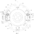
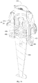
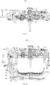
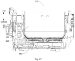
- the power coupler 100, the cover body assembly 200, the ultrasonic oscillator device 400, the ultrasonic oscillator 410, the mounting assembly of the ultrasonic device, the cooking utensil 300 and the heating apparatus are described with reference to the drawings below.
- the power coupler 100 may include: an input end component 10 and an output end component 60, wherein the input end component 10 may include: an input end base 20, a sealing cover 30, an input conductive portion 40 and a self-locking structure 50.
- the input end component 10 is separably connected to the output end component 60 in a coupling manner, such that the power coupler 100 may realize detachability between different components of an apparatus with the power coupler 100 by separating the input end component 10 from the output end component 60 in the use process, and use is more convenience.
- the cooking utensil 300 realizes power transmission through the power coupler 100, wherein the input end component 10 is mounted on an upper cover 212 of the cover body assembly 200 of the cooking utensil 300, and the output end component 60 is mounted on a cover plate 213 of the cover body assembly 200.
- the input end component 10 is separated from the output end component 60 to enable the cover plate 213 to be detachable, such that the cover plate 213 is more convenient to clean, and the risk of a short circuit or an electric shock caused by water ingress of the input end component 10 is also avoided.
- the input end component 10 is mounted on a pedestal of a boiler body 310 of the cooking utensil 300, and the output end component 60 is mounted on an inner boiler of the boiler body 310.
- the input end component 10 is separated from the output end component 60 to enable the inner boiler to be taken out from the pedestal, such that food taking and placing and cleaning of the inner boiler are more convenient.
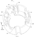
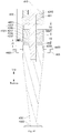
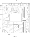
- the input end base 20 is internally provided with a slot 201 so as to be formed into a cup seat; and as shown in Fig. 9 , the input conductive portion 40 is arranged on the input end base 20 to be connected with an external power supply, and the output end component 60 is provided with an output conductive portion 62. As shown in Fig. 5-64 , when the input end component 10 is connected to the output end component 60, the output conductive portion 62 may extend into the slot 201 to be connected with the input conductive portion 40, and thus power transmission from the input end component 10 to the output end component 60 is realized. As shown in Fig. 1 and Fig.
- the output conductive portion 62 moves out of the slot 201.
- the input conductive portion 40 is located in the slot 201, a user is difficult to be in contact to the input conductive portion 40, and thus reduction in risk of the electrical shock is facilitated.
- the power coupler 100 further includes a sealing cover 30 and a self-locking structure 50, wherein the sealing cover 30 may be arranged on the input end base 20 and may move between a closing position and an opening position.
- a slot port of the slot 201 may be covered and sealed when the sealing cover 30 is located at the closing position to prevent the user from extending into the slot 210 to be in contact to the input conductive portion 40 when the input end component 10 is separated from the output end component 60, and thus the risk of the electrical shock is further lowered.
- the slot port of the slot 201 may be opened when the sealing cover 30 is located at the opening position, such that the output conductive portion 62 may extend into the slot 201 to be electrically connected to the input conductive portion 40, and the power coupler 100 may be normally used.
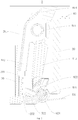
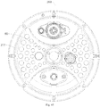
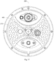
- the self-locking structure 50 may be switched between a locked state and an unlocked state. As shown in Fig. 1-2 and Fig. 25-16 , movement of the sealing cover 30 towards the opening position may be limited when the self-locking structure 50 is in the locked state; and as shown in Fig. 5 and Fig. 29 , limitation on the sealing cover 30 is released when the self-locking structure 50 is in the unlocked state.
- the sealing cover 30 is located at the closing position, and the self-locking structure 50 moves to the locked state, such that the electrical shock accident as the user pushes the sealing cover 30 to extend into the slot 201 is prevented.
- the sealing cover 30 may move to the opening position, the output conductive portion 62 may extend into the slot 201 to be connected to the input conductive portion 40, a connection portion of the input conductive portion 40 and the output conductive portion 62 is located in the slot 201, and the user may also be prevented from getting an electric shock by contacting the connection portion.
- the number of the self-locking structure 50 may be adjusted according to the actual needs.
- the power coupler 100 includes two self-locking structure 50 for illustrative purposes only.
- ordinary skill in the art may apparently understand that the solution is applied to a technical solution with one, three or more self-locking structures 50 after reading the technical solution of the present disclosure, which may also fall within the protection scope of the present disclosure.
- the power coupler 100 has a self-locking function by matching of the sealing cover 30 with the self-locking structure 50, and self locking of the input end component 10 can be realized when the input end component 10 is separated from the output end component 60, such that the input conductive portion 40 cannot be exposed outsides, the risk of the electric shock of the user is effectively lowered, and the user is safer.
- the self-locking structure 50 may realize state switching automatically and also manually by the user to meet different application demands.
- the self-locking structure 50 may automatically move the locked state; and in the process that the output end component 60 is connected to the input end component 10, the self-locking structure 50 may be switched to the unlocked state under the pushing of the output end component 60.
- state switching of the self-locking structure 50 may be realized without additional operation by the user, such that the situation that the user forgets operation to enable the input end component 10 not to be self-locked is prevented, the operation steps during mounting of the output end component 60 and the input end component 10 are also reduced, and mounting is more convenient.
- each input conductive portion 40 may include a terminal portion 41 and an electrode portion 42,
- the terminal portions 41 may be locked into the corresponding mounting clamping grooves 203 to realize connection of the input conductive portion 40 to the input end base 20, and each terminal portion 41 may be electrically connected to the external power supply.
- the terminal portions 41 may penetrate through the power supply line holes to realize external electric connection to the external power supply, or the external power supply may penetrates through the power supply line holes to realize internal electric connection to the terminal portions 41, even or the connection portions of the terminal portions 41 and the external power supply may be located in the power supply line holes respectively.
- the electrode portions 42 may be connected to the lower ends of the corresponding terminal portions 41 and may extend out of the corresponding mounting clamping grooves 203 and into the slot 201 to realize electric connection to the output conductive portion 62 in the slot 201; and as an electric connection structure is located in the slot 201, use is safer and more reliable.
- bayonets 204 may be formed in the groove bottom walls of the mounting clamping grooves 203 respectively, the terminal portions 41 may be provided with clamping plates 401, and the clamping plates 401 may be clamped into the bayonets 204 respectively to limit an axial position of the input conductive portion 40 and the input end base 20 when the terminal portions 41 is clamped into the mounting clamping grooves 203 respectively.
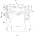
- the self-locking structure 50 may include: stoppers 51 and drive pieces 52, wherein the stoppers 51 are connected to the input end base 20 or the sealing cover 30 and may move between the first position as shown in Fig. 1-2 and Fig. 25-26 and the second position as shown in Fig. 5 and Fig. 29 .
- the stoppers 51 may stop the sealing cover 30 from moving towards the opening position when being located in the first position, such that the sealing cover 30 keeps a state of covering and sealing the slot port of the slot 201 and is always at the closing position.
- the stoppers 51 releases stopping to the sealing cover 30 when being in the second position, such that the sealing cover 30 may move towards the interior of the slot 201.
- the stoppers 51 are usually at the first position, that is, the stoppers 51 usually stop the sealing cover 30 to enable the sealing cover 30 not to move towards the opening position, such that the slot port of the slot 201 is usually in a covering and sealing state, and the effect of preventing electric shock is better.
- the drive pieces 52 may be connected to the input end base 20 or may be arranged on the output end component 60 and may drive the stoppers 51 to move to the second position when the output end component 60 is inserted into the input end component 10.
- the drive pieces 52 may switch a mounting action of the output end component 60 to movement of the stoppers towards the second position, and thus the structure design is reasonable.
- the drive pieces 52 are connected to the input end base 20, and the output end component 60 pushes the drive pieces 52 to rotate relative to the input end base 20 when the output end component 60 is inserted into the input end component 10; and in the process that the drive pieces 52 rotate from the position as shown in Fig. 1 to the position as shown in Fig. 5 , the drive pieces 52 may generate extrusion with the stoppers 51 to enable the stoppers 51 to rotate relative to the input end base 20, and thus the stoppers 51 release limitation to the sealing cover 30.
- the stoppers 51 may be rotatably connected to the input end base 20 as shown in Fig. 1 and Fig. 2 or as shown in Fig. 25 and Fig. 26 .
- the self-locking structure 50 may further includes a stopping reset pieces 53; and the stopping reset pieces 53 may be connected to the input end base 20 and may apply action forces to the corresponding stoppers 51 to enable the corresponding stoppers 51 to move towards the first position. That is, the stopping reset pieces 53 may usually drive the corresponding stoppers 51 to be at the first position, such that self locking of the input end component 10 is realized, and the situation that the user forgets operation to enable the input end component 10 to be self locked when the input end component 10 is separated from the output end component 60 is prevented.
- each stopper 51 may include: a connection portion 511, a stopping portion 512 and a drive matching portion 513.
- the stopping portions 512 and the drive matching portion 513 are connected to the connection portion 511 separately, the stopping portions 512 may stop the sealing cover 30, the drive matching portion 513 may be matched with the drive pieces 52, and the connection portions 511 is rotatably connected to the input end base 20.
- movement of the drive pieces 52 may drive the drive matching portion 513 to move, movement of the drive matching portion 513 may drive the connection portions 511 to rotate relative to the input end base 20, and thus the stopping portions 512 are driven to rotate relative to the input end base 20 to realize stopping and stopping release between the stopping portions 512 and the sealing cover 30.
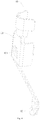
- each stopping reset piece 53 may be a torsional spring; and as shown in Fig. 18-20 , the input end base 20 may be provided with rotating shafts 21, and each connection portion 511 may be provided with a first limiting slot 5111 and a rotating drum 5112.
- the rotating drums 5112 may be arranged on the corresponding rotating shafts 21 in a sleeved manner to rotate, such that the stopper 51 is difficult to offset or fall off when rotating relative to the input end base 20, and rotation is smoother.
- each torsional spring may be sleeved on the corresponding rotating drum 5112, one end of each torsional spring is connected to the input end base 20, and the other end of each torsional spring may be arranged in the corresponding first limiting slot 5111, such that each torsional spring is firmly and reliably fixed and difficulty loosened.
- the rotating shafts 21 and the rotating drums 5112 may be exchanged in position, that is, the input end base 20 may be provided with the rotating drums 5112, and the connection portions 511 may be provided with the rotating shafts 21, which may also realize rotatable connection between the stoppers 51 and the input end base 20.
- connection structure of one end of each torsional spring and the input end base 20 may be provided with the fixed holes or fixed grooves, and one ends of the torsional springs may extend into the corresponding fixed holes or fixed grooves, such that one ends of the torsional springs are more reliable in fixing with the input end base 20.
- one ends of the torsional springs may be abutted to the inner wall face of the input end base 20, which may also provide supporting to the torsional springs when the other ends of the torsional springs are extruded by the corresponding stoppers 51 to enable the torsional springs to apply the action forces to the corresponding stoppers 51.
- two rotating shafts 21 are provided, and a fixed end of each rotating shaft 21 is connected to the input end base 20; two rotating drums 5112 are provided and are arranged at the two ends of a rotating axis of the corresponding stopper 51; and the rotating shafts 21 are clamped into the rotating drums 5112 in one-to-one correspondence.
- the stoppers 51 are mounted on the input end base 20, the rotating drums 5112 are inserted in radial directions of the corresponding rotating shafts 21 until the rotating shafts 21 are clamped into the corresponding rotating drums 5112.
- At least a portion of an end surface of a free end of each rotating shaft 21 is formed into an inclined surface, the inclined surface slantingly extends in a direction close to the downside and close to another rotating shaft 21 along an inserting manner of the corresponding rotating drum 5112.
- the inclined surfaces may guide the corresponding rotating drum 5112, such that mounting of the stoppers 51 is more simple and labor saving.
- the first limiting slots 5111 may be arranged on the corresponding stopping portions 512 or drive matching portions 513.
- the stopping portions 512 there are two stopping portions 512 arranged at the two axial ends of each stopper 51 respectively, a drive matching portion 513 is arranged at the middle part of each stopper 51, and the size of the free end of the drive matching portion 513 in the axial direction of each stopper 51 is smaller than that of the fixed end of the corresponding drive matching portion 513 in the axial direction of each stopper 51.
- Flangings are formed at one sides, away from each other, of the two stopping portions 512, the flangings and the stopping portions 512 collectively define the first limiting slots 5111; the two torsional springs may act on the corresponding stopper 51 from the two axial ends of the stopper 51 when being inserted into the two first limiting slots 5111 respectively, such that the stopper 51 is more uniformly stressed; and furthermore, interference is not generated on both of matching of the drive pieces 52 and the corresponding drive matching portions 513 and matching of the torsional springs, the stoppers 512 and the sealing cover, such that structure design is more reasonable.
- limiting mesas 301 may be arranged on the outer peripheral face of the sealing cover 30.
- the stoppers 51 may be interfered with the corresponding limiting mesas 301 to stop the sealing cover 30 from moving towards the opening position when being at the first position; and the stoppers 51 may move outsides to avoid the corresponding limiting mesas 301 when being at the second position.
- each stopper 51 includes the stopping portion 512
- the sealing cover 30 move upwards to realize movement from the first position to the second position
- each limiting mesa 301 is a stepped platform formed at the outer peripheral face of the sealing cover 30; and when the stoppers 51 are located at the first position, the free ends of the stopping portions 512 may be abutted to the upper surfaces of the corresponding stepped platform or are spaced from the upper surfaces of the corresponding stepped platform by a relatively small distance, such that the sealing cover 30 cannot move into the slot to expose the output conductive portion 40.
- the second position 512 rotate along with the corresponding stoppers 51, the free ends of the second positions 512 move towards a direction of the axis of the sealing cover 30 in a radial direction of the sealing cover 30, such that the free ends of the second position 512 are located on the outer sides of the corresponding stepped platforms to release limiting effect to the stepped platforms, and the sealing cover 30 may move upwards.
- each stopper 51 may be further provided with a limiting convex rib 514; when the sealing cover 30 is not mounted on the input end base 20, the limiting convex rib 514 may be abutted to the input end base 20 to limit an angle of each stopper 51 rotating inwards, and thus the situation that the sealing cover 30 is interfered with each stopper 51 when being mounted is prevented.
- the angle of each stopper 51 rotating inwards may be limited by abutting the corresponding limiting convex rib 514 to the input end base 20 and may also be limited by abutting each stopper 51 to the sealing cover 30, which are all within the scope of the present disclosure.
- each drive piece 52 is rotatably connected to the input end base 20
- the self-locking structure 50 may further includes the drive reset pieces 54
- each drive reset piece 54 may be connected to the input end base 20 and may apply reset force to the corresponding drive piece 52 to enable the drive piece 52 to be restored to an initial position.
- the corresponding drive piece 52 may automatically rotate to the initial position as shown in Fig. 1 , such that each drive piece 52 releases the drive action to the corresponding stopper 51 to enable the stopper 51 to move to the first position to limit movement of the sealing cover 30.
- the input end component 60 may compress the drive reset pieces 54 when being inserted into the input end component 10, such that the reset forces of the drive reset pieces 54 are overcome to enable the corresponding drive pieces 52 to rotate.
- each drive piece 52 may include: a drive connection portion 521, a drive portion 522 and a limiting matching portion 523.
- Each drive portion 522 may be connected to the corresponding drive connection portion 521, may drive the corresponding stopper 51 to rotate and may be rotatably connected to the input end base 20.
- each drive piece 52 may drive the corresponding drive portion 522 to rotate when rotating relative to the input end base 20 to realize matching and matching escapement of each drive piece 52 with the corresponding stopper 51.
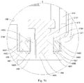
- each limiting matching portion 523 may be connected to the corresponding drive connection portion 521; and as shown in Fig. 16 and Fig. 17 , the input end base 20 may be provided with limiting portions 26.
- the limiting matching portion 523 may be abutted to the corresponding limiting portion 26 under the reset forces of the drive reset pieces 54 to limit the drive pieces 52, such that matching escapement of the drive pieces 52 with the input end base 20 is prevented.
- the drive reset pieces 54 may be torsional springs
- the input end base 20 may be provided with shaft slots 221
- the limiting matching portions 523 may be provided with second limiting slots 5231 respectively
- the drive connection portions 521 may be provided with shaft rods 5211 respectively
- the shaft rods 5211 may be arranged in the shaft slots 221 respectively and may rotate in the shaft slots 221 respectively, such that the drive pieces 52 are difficult to offset or fall off when rotating relative to the input end base 20, and rotation is smoother.
- the input end base 20 may be provided with shaft slots 221
- the limiting matching portions 523 may be provided with second limiting slots 5231 respectively
- the drive connection portions 521 may be provided with shaft rods 5211 respectively
- the shaft rods 5211 may be arranged in the shaft slots 221 respectively and may rotate in the shaft slots 221 respectively, such that the drive pieces 52 are difficult to offset or fall off when rotating relative to the input end base 20, and rotation is smoother.
- each torsional spring may be sleeved on the corresponding shaft rod 5211, one end of each torsional spring is connected to the input end base 20, and the other end of each torsional spring may be arranged in the corresponding first limiting slot 5231, such that each torsional spring is firmly and reliably fixed and difficulty loosened.
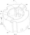
- mounting holes 202 may be formed in the bottom wall of the input end base 20, the drive pieces 52 may be arranged at the corresponding mounting holes 202, mounting seats 22 may be arranged on the edges of the corresponding mounting holes 202, the shaft slots 221 may be arranged on the corresponding mounting seats 22 to enable the mounting seats 22 to support the corresponding drive pieces 52 from the two axial ends of the drive pieces 52, the drive pieces 52 is more uniformly stressed, and rotation is smoother.
- the limiting portions 26 may be buckles which are connected to the corresponding mounting seats 22 and extend inwards, and "inwards" herein refers to orientations facing the mounting holes 202, such that the drive pieces 52 rotate under the effect of reset forces of the torsional springs, and the inner ends of the buckles may be abutted to the corresponding limiting matching portions 523 to prevent the drive pieces 52 to rotate to the outsides of the corresponding mounting holes 202.
- each shaft rod 5211 may be provided with a retaining rib 5212, the retaining rib 5212 may limit the corresponding torsional spring in the axial direction of the shaft rod 5211, and the situation that the reset force is influenced due to overlarge displacement of the torsional spring in the axial direction of the shaft rod 5211 is prevented.
- each drive portion 522 may be connected to the middle part of the corresponding shaft rod 5211 to enable the corresponding drive piece 52 to be uniformly stressed, and the action force of the drive piece 52 to the corresponding stopper 51 is more stable.
- a check rib 524 may be arranged at the middle part of each shaft rod 5211; and when each drive piece 52 rotates under the effect of the reset force of the corresponding torsional spring, the check rib 524 may be abutted to the bottom wall face of the input end base 20 to limit the corresponding drive piece 52, and the situation that the drive piece 52 is departed from the input end base 20 due to overlarge rotation angle of the drive piece 52 is prevented.
- the check ribs 524 and the drive portions 522 may be distributed in circumferential directions of the corresponding shaft rods 5211, such that stress uniformity of the drive pieces 52 may be further improved, interference on structures of the check ribs 524 and the drive portions 522 may be prevented, and the structure design is reasonable.
- the power coupler 100 may include the limiting portions 26 and the limiting matching portion 523 only, may also include the check ribs 524 only, or is provided with the limiting portions 26, the limiting matching portion 523 and the check ribs 524 at the same time, which may all limit rotating angles of the drive pieces 52.
- the output end component 60 may include the output end base 61
- the output end base 61 may include a base main body 611 and a convex portion 612
- the convex portion 612 is arranged on one side of the base main body 611 in a protruding manner to enable the output end base 61 to form into a convex-shaped structure, such that a dead angle is difficultly generated, and accumulation of residues is avoided.
- the convex portion 612 may extend into the slot 201 to realize connection of the output end component 60 to the input end component 10, such that a connection mode is simple, and connection is liable to disassemble.
- the output conductive portion 62 may be connected to the output end base 61 and may be exposed from the outer peripheral face of the convex portion 612, such that the output conductive portion 62 may be connected to the input conductive portion 40 as the convex portion 612 extends into the slot 201. Furthermore, the convex portion 612 may drive the self-locking structure 50 to move when extending into the slot 201 to enable the self-locking structure 50 to be switched to the unlocked state; and as unlocking and mounting are performed at the same time, operation steps are less, and mounting is more convenient.
- convex ribs 613 may be arranged on the outer peripheral face of the convex portion 612 and extend in the axial direction of the convex portion 612. In the process that the convex portion 612 extends into the slot 201, the convex ribs 613 may drive the self-locking structure 50 to move.
- the convex ribs 613 may be matched with the interiors of the mounting holes 202 respectively, the mounting holes 202 may limit the circumferential direction of the convex portion 612 to prevent the convex portion 612 from arbitrarily rotating, such that alignment of the input conductive portion 40 and the output conductive portion 62 is more accurate.
- a protruding height L of each convex rib 613 protruding from the outer peripheral face of the convex portion 612 satisfies: 0mm ⁇ L ⁇ 3mm, for example, in some specific embodiments, the protruding height L of each convex rib 613 protruding from the outer peripheral face of the convex portion 612 may be 1mm, 1.5mm, 2mm, 2.5mm and the like separately. L>0mm, such that alignment of the convex ribs 613 and the self-locking structure 50 is more convenient and accurate; and if L ⁇ 3mm, the radial size of the power coupler 100 may be prevented from being too large, and the structure is more compact.
- each convex rib 613 exceeds the end surface of one end, far away from the base main body 611, of the convex portion 612, such that the alignment of each convex rib 613 and the self-locking structure 50 is more convenient and accurate; and in addition, the exceeding height H may satisfy: 1mm ⁇ H ⁇ 6mm, for example, in some specific embodiments, the exceeding height H may be 2mm, 3mm, 4mm, 5mm and the like separately. H ⁇ 6mm, such that overlong axial length of the power coupler 100 may be prevented, and the structure is more compact. Further, the exceeding height H may satisfy: 2mm ⁇ H ⁇ 4mm.
- the drive portions 522 of the drive pieces 52 may be formed into drive plates, the convex ribs 613 may be abutted to the surface of one side, facing away from the slot 201, of the corresponding drive plates to push the corresponding drive plates to rotate around the axis, and thus opening of the self-locking structure 50 and the sealing cover 30 is realized.
- a waterproof air-permeable membrane 63 may be arranged on the top wall of the convex portion 612, such that inside sealing of the output end base 61 may be realized to prevent components in the output end base 61 from being wet by water ingress, and heat dissipation may be realized to prevent the situation that the components in the output end base 61 are damaged due to overhigh temperature in the output end base 61.
- the output conductive portion 62 may include a positive conductive sheet, a negative conductive sheet and a grounding conductive sheet, three output slots may be formed in the outer peripheral face of the convex portion 612, the positive conductive sheet, the negative conductive sheet and the grounding conductive sheet are inlaid into the three output slots in one-to-one correspondence, each output slot communicates with a base cavity of the output end base 61 through a line passing hole, and a positive electrode line 471, and a negative electrode line 472 and a grounding line 470 may penetrate through the line passing hole through the base cavity of the output end base 61 to be connected with the positive conductive sheet, the negative conductive sheet and the grounding conductive sheet respectively.
- An external structure of the output end component 60 is more simple, a dead angle is difficultly generated, and accumulation of the residues is avoided.
- the output end base 61 may shield wires, such that on one hand, an electric connection structure may be more firm and reliable; and on the other hand, in severe environments with water spots, oil contamination and the like, stains are difficult to contaminate an electric connection structure, and cleaning is more convenient.
- the stoppers 51 may be magnetic pieces, for example, magnets, ferrous metal and the like.
- the drive pieces 52 may be magnetic drive pieces 64; the magnetic drive pieces 64 may be arranged on the output end component 60, for example, be connected to the output end base 61; and furthermore, the magnetic drive pieces 64 may be magnetically matched with the corresponding stoppers 51 to enable the stoppers 51 to form magnetic drive self-locking pins, and the magnetic drive self-locking pins may move between the first position and the second position under the effect of magnetic force.
- the magnetic drive pieces 64 may be less distant from the corresponding stoppers 51, and the stoppers 51 move to the second position under the effect of the magnetic forces of the corresponding magnetic drive pieces 64.
- Position transformation of the stoppers 51 may be realized automatically without additional operation by the user, such that the situation that the user forgets operation to enable the input end component 10 not to be self-locked is prevented, the operation steps during mounting of the output end component 60 and the input end component 10 are also reduced, and mounting is more convenient. As shown in Fig.
- the sealing cover 30 may move to the opening position under the pushing of the output end base 61, the output conductive portion 62 may extend into the slot 201 to be connected to the input conductive portion 40, a connection portion of the input conductive portion 40 and the output conductive portion 62 is located in the slot 201, and the user may also be prevented from getting an electric shock by contacting the connection portion.
- the numbers of the stoppers 51 and the magnetic drive pieces 64 may be adjusted according to the actual needs.
- the power coupler 100 includes two stoppers 51 and one magnetic drive piece 64 for illustrative purposes only.
- ordinary skill in the art may apparently understand that the solution is applied to a technical solution with one, three or more stoppers 51 or more magnetic drive pieces 64 after reading the technical solution of the present disclosure, which may all fall within the protection scope of the present disclosure.
- the power coupler 100 form a magnetically-attracting coupler structure by matching of the sealing cover 30, the stoppers 51 and the magnetic drive pieces 64 and has a magnetic self-locking structure, and self locking of the input end component 10 can be realized when the input end component 10 is separated from the output end component 60, such that the input conductive portion 40 cannot be exposed outsides, the risk of the electric shock of the user is effectively lowered, and the user is safer; and the input end component 10 may also be unlocked automatically when the input end component 10 is connected to the output end component 60, and disassembly is more convenient.
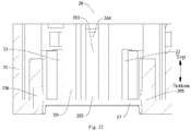
- the stoppers 51 may be arranged on the sealing cover 30 and may translate in the radial direction of the sealing cover 30. As shown in Fig. 32-34 , stopping slots 205 may be formed in the inner peripheral face of the slot 201. As shown in Fig. 25 and Fig. 26 , the stoppers 51 may extend into the corresponding stopping slots 205 when being at the first position to limit the position of the sealing cover 30 in the slot 201 in the axial direction. As shown in Fig.
- the stoppers 51 may move out of the corresponding stopping slots 205 when being at the second position; and at this time, the matching of the stoppers 51 with the input end base 20 is escaped, and the sealing cover 30 may move in the slot 201 in the axial direction.
- the sealing cover 30 may include: a sealing plate 34 and a side wall 35, and the side wall 35 may be connected to the outer peripheral edge of the sealing plate 34 and is located on one side of the sealing plate 34 to form a sealing cover slot 302 by matching with the sealing plate 34.
- through holes 351 may be formed in the side wall 35, and the stoppers 51 may be arranged in the sealing cover slot 302. The stoppers 51 may extend into the corresponding through holes 351 to realize connection of the stoppers 51 and the sealing cover 30.
- the outer ends of the stoppers 51 may penetrate through the corresponding through holes 351 to extend into the corresponding stopping slots 205 when the stoppers 51 are at the first position, such that the stoppers 51 may enable the through holes 351 and the stopping slots 205 to be fixed at the axial position of the sealing cover 30, and the sealing cover 30 and the input end base 20 are axially fixed.
- the stopping reset pieces 53 may be arranged in the sealing cover slot 302 so as to apply the action forces to the corresponding stoppers 51, and thus the structure is compact.
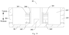
- the sealing plate 34 may be provided with sealing plate bulges 341 located in the sealing cover slot 302, and the stopping reset pieces 53 may be helical springs; and as shown in Fig. 38 , outer bulges 515 may be arranged on the outer peripheral faces of the corresponding stoppers 51.
- the helical springs may be arranged on the corresponding stoppers 51 in the sleeved manner, and the two ends of the helical springs may be abutted to the sealing plate bulges 341 and the outer bulges 515 respectively.
- the outer bulges 515 may compress the helical springs when the stoppers 51 is affected by the magnetism to move to the second position.
- the outer bulges 515 may define movement strokes of the stoppers 51 between the first position and the second position; when the stoppers 51 move to the first position under the effect of the corresponding helical springs, the outer bulges 515 may be abutted to the inner peripheral face of the side wall 35 to prevent the stoppers 51 from thoroughly departed from the corresponding through holes 351 outwards.
- limiting slots 342 may be formed in the sealing plate bulges 341 respectively and may extend in the radial direction of the sealing cover 30, and the inner ends of the stoppers 51 may be arranged in the corresponding limiting slots 342 in a translating and penetrating manner.
- the limiting slots 342 may limit movement routes of the stoppers 51 to prevent the situation that the stoppers 51 offset to escape matching with the corresponding through holes 351 to influence the self-locking function of the input end component 10.
- each limiting slot 342 in the radial direction of the sealing cover 30 are both opened, such that the stoppers 51 may penetrate out of the two ends of the corresponding limiting slots 342.
- the sealing plate 34 may further be provided with stopping convex ribs 343 located in the sealing cover slot 302; and when the stoppers 51 are located at the second position, the inner ends of the stoppers 51 may be abutted to the corresponding stopping convex ribs 343.
- the stopping convex ribs 343 may limit the movement strokes of the stoppers 51, and design is reasonable.
- each sealing plate bulge 341 may include two arm portions, a limiting slot 342 is formed between the two arm portions, each stopper 51 may be clamped into the corresponding limiting slot 342 from a gap between the free ends of the two arm portions, and mounting is convenient; and the free ends of the two arm portions extend, close to each other, such that each stopper 51 is difficultly departed after being clamped into the corresponding limiting slot 342, and fixing is more reliable.
- multiple stopping slots 205 and stopping reset pieces 53 may also be provided, and the stoppers 51, the stopping slots 205 and the stopping reset piece 53 may be arranged in one-to-one correspondence.
- the multiple stopping slots 205 may be arranged spaced from each other in the circumferential direction of the slot 201 to stop the sealing cover 30 from multiple positions in the circumferential direction of the sealing cover 30, such that the sealing cover 30 is more uniformly stressed.
- the multiple stoppers 51 may move towards the second position under the magnetic attraction of the magnetic drive piece 64.
- the multiple stoppers 51 may move under the effect of one magnetic drive piece 64, and the number of the magnetic drive piece 64 is less, such that the structure is more simple, and the cost is lower.
- the output end component 60 may drive the stoppers 51 to move towards the second position when being abutted to the sealing cover 30 of the input end component 10 as shown in Fig. 27 and Fig. 28 and may drive the stoppers 51 to move towards the second position when being spaced from the input end component 10 by a certain distance.
- an elastic piece 70 may also be arranged between the sealing cover 30 and the bottom wall face of the slot 201, and the sealing cover 30 and the bottom wall face of the slot 201 may perform axial positioning on the elastic piece 70.
- the elastic piece 70 may enable the sealing cover 30 to be restored to the closing position, i.e., the elastic piece 70 may usually drive the sealing cover 30 to cover and seal the slot port of the slot 201.
- the elastic piece 70 may drive the sealing cover 30 to move automatically to the closing position without manual operation, such that use is more convenient.
- a positioning column 251, protruding towards the interior of the slot 201 may be arranged on the bottom wall face of the slot 201; and as shown in Fig. 11 , the sealing cover 30 may be provided an inner cylinder 32 and an outer cylinder 33 which are coaxially arranged, one end of the elastic piece 70 may be arranged on the positioning column 251 in the sleeved manner, the other end of the elastic piece 70 may be inserted into the inner cylinder 32, and the inner cylinder 32 and the positioning column 251 may limit the radial position of the elastic piece 70 to prevent the situation that the drive effect on the sealing cover 30 is influenced by radial twisting deformation or displacement of the elastic piece 70.
- the positioning groove 206 may be formed in the bottom wall face of the slot 201, the sealing cover 30 may be provided with positioning bosses 344, and the two ends of the elastic piece 70 may be abutted to the interior of the positioning groove 206 and the positioning bosses 344 respectively.
- the positioning groove 206 and the positioning bosses 344 may limit the radial position of the elastic piece 70 to prevent the situation that the drive effect on the sealing cover 30 is influenced by radial twisting deformation or displacement of the elastic piece 70.
- the positioning boss 344 may extend to form arch-shaped bulges, each arch-shaped bulge may be provided with an arch-shaped stepped face, the elastic piece 70 may be a helical spring, the helical spring may be arranged on the arch-shaped bulges in the sleeved manner and is abutted to the arch-shaped stepped faces, and the arch-shaped bulges are more suitable to the helical spring, such that the limiting effect on the helical spring is better.
- the stopping convex rib 343 may be located between the two arch-shaped bulges, and the arch-shaped stepped faces are higher than or equal to the corresponding sealing plate bulges 341.
- the stoppers 51 may extend into a space between the two arch-shaped bulges to be abutted to the stopping convex ribs 343, such that the structure is more compact; and in addition, interference cannot be generated between the stoppers 51 and the elastic piece 70.
- the edge plate 27, extending inwards may be arranged at the slot port of the slot 201; and as shown in Fig. 36 and Fig. 37 , the positioning convex portions 31, protruding outwards, may be arranged on the outer peripheral face of the sealing cover 30 and may abutted to the edge plate 27 to limit the sealing cover 30 when the sealing cover 30 is located at the closing position, such that the sealing cover 30 is prevented from departing from the slot port of the slot 201, and fixing of the sealing cover 30 is more reliable.
- guide convex ribs 23 may be arranged on the inner peripheral face of the slot 201 and extend to the edge plate 27 in the axial direction of the slot 201; and as shown in Fig. 36 and Fig. 37 , a positioning slot 311 may be formed in each positioning convex portion 31 and may be movably matched with the corresponding guide convex rib 23 to guide and limit movement of the sealing cover 30, such that the situation that the sealing cover 30 is inclined and jammed and the situation that the sealing cover 30 rotates to enable the stoppers 51 to be staggered with the stopping slots 205 are prevented, and movement of the sealing cover 30 is smoother.
- the input end base 20 may include a shell 24 and a top cover 25, the top cover 25 may cover one axial end of the shell 24 to define the slot 201 with the shell 24 together, the inner surface of the top cover 25 is formed into the bottom wall face of the slot 201, the positioning columns 251 may be arranged on the top cover 25, and the other axial end of the shell 24 may be formed into the slot port of the slot 201.
- the structures of the input conductive portion 40, the stoppers 50 and the like may be mounted in the shell 24 from one axial end of the shell 24 when the top cover 25 is not mounted on the shell 24, such that mounting is more convenient and is liable to operate.
- an opening may be formed in the top cover 25, as shown in Fig. 1 , Fig. 5 , Fig. 25 , Fig. 27 and Fig. 30 ; and the input conductive portion 40 may extend out of the slot 201 through the opening to be connected to a power input wire, or the power input wire may extend into the slot 201 through the opening to be connected to the input conductive portion 40.
- the output end component 60 may include the output end base 61
- the output end base 61 may include a base main body 611 and a convex portion 612
- the convex portion 612 is arranged on one side of the base main body 611 in the protruding manner to enable the output end base 61 to form into the convex-shaped structure, such that a dead angle is difficultly generated, and accumulation of residues is avoided.
- the convex portion 612 may extend into the slot 201 to realize connection of the output end component 60 to the input end component 10, such that a connection mode is simple, and connection is liable to disassemble.
- the output conductive portion 62 may be connected to the output end base 61 and may be exposed from the outer peripheral face of the convex portion 612, such that the output conductive portion 62 may be connected to the input conductive portion 40 as the convex portion 612 extends into the slot 201. Furthermore, the convex portion 612 may drive the sealing cover 30 to move when extending into the slot 201, and the magnetic drive pieces 64 may be mounted on the convex portion 612 to drive the corresponding stoppers 51 to move towards the second position before the convex portion 612 is inserted into the slot 201, such that insertion of the convex portion 612 into the slot 201 is smoother, the operation steps are less, and mounting is more convenient.
- the magnetic drive pieces 64 may be magnets built in the convex portion 612, such that the appearance of the convex portion 612 is simple and beautiful; and in addition, the magnets are strong in drive forces to the stoppers 51.
- the present disclosure does not made particular limitation to a fixing mode of the magnets, for example, the magnets may be connected to the inner wall face of the convex portion 612 in an adhering manner, a clamping manner, through the corresponding fasteners or the like.
- the convex portion 612 and the base main body 611 may be an integral rubber seat, the structure is more simple, and the processing procedures and the assembly procedures may be reduced.
- the power coupler 100 according to a specific embodiment of the present disclosure is described in details with reference to the drawings below. It should be understood that the following descriptions are for illustrative purposes only, but not to be construed as limiting the present disclosure.
- the input end component 10 of the power coupler 100 is mounted on the upper cover 212 of the cover body assembly 200
- the output end component 60 is mounted on the cover plate 213 of the cover body assembly 200
- the magnetic drive pieces 64 are the magnets
- the stoppers 51 are magnetic drive self-locking pins
- the stopping slots 205 are self-locking holes.
- the output end component 60 when the cover plate 213 is inserted into the upper cover 212, the output end component 60 approaches the interpose 10, the magnets approach the corresponding magnetic drive self-locking pins, and the magnetic drive self-locking pins compress the corresponding stopping reset pieces 53 to move inwards under the effect of the magnets and are departed from the corresponding self-locking holes of the input end base 20 so as to be in an opening state.
- the output end component 60 may push the sealing cover 30 to compress the elastic piece 70 to move upwards, such that the convex portion 612 of the output end component 60 may be inserted into the slot 201 of the input end component 10 for power coupling.
- the ultrasonic oscillator device 400 includes an ultrasonic oscillator 410 and the power coupler 100 according to the embodiment of the first aspect of the present disclosure.
- one end of the output end component 60 is in coupling connection to the input end component 10, and the other end of the output end component 60 is electrically connected to the ultrasonic oscillator 410.
- the external power supply may supply power to the ultrasonic oscillator 410 by matching the output end component 60 to the input end component 10 to generate ultrasonic waves.
- the ultrasonic oscillator 410 may include: a piezoelectric assembly 4201, a first end block 4202, a second end block 4208, an oscillation rod 430, a first insulating ring 480 and a pre-tightening piece 451.
- the ultrasonic oscillator 410 of the ultrasonic oscillator device 400 according to the embodiment of the second aspect of the present disclosure may be an ultrasonic oscillator 410 according to the embodiment of the third aspect of the present disclosure.
- the piezoelectric assembly 4201 may include piezoelectric sheets (for example, piezoelectric ceramics) 11 and electrode sheets 4207, and the electrode sheets 4207 may be connected to the corresponding piezoelectric sheets 4206.
- the electrode sheets 4207 When the electrode sheets 4207 are energized, voltages at the two end surfaces of the piezoelectric sheets 4206 may be varied; and the piezoelectric sheets 4206 generate high-frequency oscillation under current excitation by using the inverse piezoelectric effect, conversion from electric power to mechanical power is realized, and the ultrasonic waves are generated.
- the first end block 4202 may be arranged at one axial end of the piezoelectric assembly 4201, and the second end block 4208 may be arranged at the other axial end of the piezoelectric assembly 4201, such that the ultrasonic oscillator 400 may be formed into a sandwich type ultrasonic oscillator device; the first end block 4202 and the second end block 4208 are matched to be capable of fixing the piezoelectric assembly 4201 to improve the stability of the piezoelectric assembly 4201; and a resonance frequency of the ultrasonic oscillator 410 may be adjusted at the same time, and energy transfer may be performed.
- the sandwich type ultrasonic oscillator device is liable to process and is liable in adjusting a frequency, and the structure is simple.
- the ultrasonic waves generated by the piezoelectric assembly 4201 may be transferred outwards in an indirect mode of transferring the ultrasonic waves by a medium and also in an entering mode that the oscillation rod 430 directly goes deep into the medium for working.
- the oscillation rod 430 may be arranged at one end, far away from the piezoelectric assembly 4201, of the second end block 4208, and mechanical oscillation generated by the piezoelectric assembly 4201 may be transferred to the oscillation rod 430 through the second end block 4208, may be continuously transferred along the oscillation rod 430 and then may be emitted outwards to be acted on a propagation medium.
- the ultrasonic oscillator works, voltage of each electrode sheet is several times higher than the mains voltage, and thus the ultrasonic oscillator is dangerous.
- the design of the ultrasonic oscillator has the creepage phenomenon and has a weak current; and the user may have a sense of electric shock in the using process and in a touchable application scenario, and certain security risks are generated.
- the first insulating ring 480 may be arranged between the piezoelectric assembly 4201 and the second end block 4208 and may isolate the piezoelectric assembly 4201 from the second end block 4208, a distance between the piezoelectric assembly 4201 and the second end block 4208 is increased, and in addition, a high-voltage creepage phenomenon occurring in the working process of the piezoelectric assembly 4201 is isolated, such that a current cannot be transferred to the second end block 4208 from the piezoelectric assembly 4201, and the risk that the user gets an electric shock by touching the second end block 4208 is lowered.
- the pre-tightening piece 451 may penetrate into the first end block 4202, the pre-tightening piece 4201, the first insulating ring 480, the second end block 4208 and the oscillation rod 430 to apply sufficient axial pre-tightening force to the first end block 4202, the pre-tightening piece 4201, the first insulating ring 480, the second end block 4208 and the oscillation rod 430, such that the first end block 4202, the pre-tightening piece 4201, the first insulating ring 480, the second end block 4208 and the oscillation rod 430 are connected together, and connection is firm.
- a contact portion of the pre-tightening piece 451 and the piezoelectric assembly 4201 is a plastic piece, or the pre-tightening piece 451 is formed into the plastic piece, such that insulating arrangement may be formed between the pre-tightening piece 451 and the piezoelectric assembly 4201.
- the pre-tightening piece 451 may isolate the first end block 4202, the pre-tightening piece 4201 the second end block 4208 and the oscillation rod 430, on one hand a short circuit of the pre-tightening piece 4201 may be prevented; and on the other hand, the pre-tightening piece 451 may cause insulation among the first end block 4202, the second end block 4208, the oscillation rod 430 and the piezoelectric assembly 4201, and the user is further prevented from getting the electric shock.
- the second end block 4208 may be isolated from the piezoelectric assembly 4201, such that the high-voltage creepage phenomenon is effectively improved, the risk of the electric shock of the user is lowered, hurts on a human body are avoided, and the ultrasonic oscillator 410 is safer and more reliable.
- the first insulating ring 480 may be a ceramic ring, for example, an alumina ceramic ring or a zirconia ceramic ring, is good in the insulativity, resists high temperature and wear and thus is beneficial to prolonging the service life of the ultrasonic oscillator 410.
- the thickness H1 of the first insulating ring 480 may satisfy: 4mm ⁇ H1 ⁇ 7mm, for example, the thickness H1 may be 4.5mm, 5mm, 5.5mm, 6mm, 6.5mm and the like. Therefore, the high-voltage creepage phenomenon may be guaranteed to be isolated, too long axial length of the first insulating ring 480 or large impedance caused by overlarge thickness H1 of the first insulating ring 480 is also prevented, decrease in working temperature of the ultrasonic oscillator 410 is facilitated, and the ultrasonic oscillator 410 may keep good energy transfer efficiency.
- the thickness H2 of the piezoelectric sheet 4206 may satisfy: 3mm ⁇ H2 ⁇ 6mm, for example, the thickness H2 of the piezoelectric sheet 4206 may be 3.5mm, 4mm, 4.5mm, 5mm, 5.5mm and the like; and the thickness H1 of the first insulating ring 480 and the thickness H2 of the piezoelectric sheet 4206 may satisfy: 10mm ⁇ H1+H2 ⁇ 13mm, for example, H1+H2 may be 10.5mm, 11mm, 11.5mm, 12mm, 12.5mm and the like.
- a distance between the electrode sheet 4207 and the second end block 4208 of the piezoelectric assembly 4201 may be further ensured to be long enough, such that the high-voltage creepage phenomenon may be better isolated, and meanwhile, serious heating of the piezoelectric assembly 4201 caused by too long axial length of the ultrasonic oscillator 410 is prevented.
- the ultrasonic oscillator 410 may further include an insulating sleeve 500, the insulating sleeve 500 may be arranged between the pre-tightening piece 451 and the piezoelectric assembly 4201, for example, the insulating sleeve 500 may be arranged on the pre-tightening piece 451 in the sleeved manner to be capable of forming insulating arrangement between the pre-tightening piece 451 and the piezoelectric assembly 4201.
- the insulating sleeve 500 may isolate the first end block 4202, the piezoelectric assembly 4201, the second end block 4208 and the oscillation rod 430, such that a short circuit of the piezoelectric assembly 4201 is prevented, and the insulating effect on the first end block 4202, the second end block 4208 and the oscillation rod 430 is better.
- the pre-tightening piece 451 may be an insulating fastener, for example, plastic fastener and the like and may also be a metal fastener, for example, a stainless steel bolt and the like.
- a first circular slot 4218 may be formed in the inner peripheral face of one end, facing the first insulating ring 480, of the second end block 4208 and may be internally provided with a first sealant layer 490.
- the first sealant layer 490 may seal the gap between the inner peripheral face of the first insulating ring 480 and the pre-tightening piece 451, and high-voltage creepage from the inner peripheral face of the first insulating ring 480 to the second end block 4208 is further isolated, such that the insulativity of the second end block 4208 is better.
- one end of the insulating sleeve 500 may extend into the first circular slot 4218, such that the area, isolating the first end block 4202, the second end block 4208 and the oscillation rod 430, of the insulating sleeve 500 may be increased to improve the insulating effect, and the first circular slot 4218 may limit the insulating sleeve 500 to enable fixing of the insulating sleeve 500 to be more stable. For example, when the axial end surface of the insulating sleeve 500 is abutted to the bottom slot surface of the first circular slot 4218, the axial position of the insulating sleeve 500 may be limited.
- the first sealant layer 490 is at least arranged between the outer peripheral face of the insulating sleeve 500 and the inner peripheral face of the first circular slot 4218 to seal the gap between the outer peripheral face of the insulating sleeve 500 and the inner peripheral face of the first insulating ring 480 with glue and shield the outer peripheral face of the insulating sleeve 500, such that the creepage phenomenon at a corner formed by the first insulating ring 480 and the insulating sleeve 500 is prevented.
- the thickness of the first insulating ring 480 may be reduced according to the actual condition to lower the impedance and the calorific value of the piezoelectric assembly 4201, and in addition, the production cost of the first insulating ring 480 may be lowered.
- the arrangement position of the first sealant layer 490 is not limited to be between the outer peripheral face of the insulating sleeve 500 and the inner peripheral face of the first circular slot 4218.
- the first sealant layer 490 may further be arranged between the axial end surface, far away from the first end block 4202, of the insulating sleeve 500 and the bottom slot surface of the first circular slot 4218 to seal the axial end surface, far away from the first end block 4202, of the insulating sleeve 500 with the glue, and thus creepage caused by a slit between the outer peripheral face of the insulating sleeve 500 and the first sealant layer 490 is prevented.
- the ultrasonic oscillator 410 may further include a second insulating ring 481.
- the pre-tightening piece 451 may penetrate through the second insulating ring 481 to enable the second insulating ring 481 to be connected to the first end block 4202, the piezoelectric assembly 4201, the first insulating ring 480, the second end block 4208 and the oscillation rod 430 together;
- the second insulating ring 481 may be arranged between the piezoelectric assembly 4201 and the first end block 4202 to isolate the piezoelectric assembly 4201 from the first end block 4202, such that a distance between the piezoelectric assembly 4201 and the first end block 4202 is increased, the high-voltage creepage phenomenon in the working process of the piezoelectric assembly 4201 is isolated, the electric shock of the user caused by energization of the first end block 4202 is prevented, and user is safer.
- the second insulating ring 481 may be a ceramic ring, for example, an alumina ceramic ring or a zirconia ceramic ring, is good in the insulativity, resists high temperature and wear and thus being beneficial to prolonging the service life of the ultrasonic oscillator 410.
- the thickness H3 of the second insulating ring 481 may satisfy: 4mm ⁇ H3 ⁇ 7mm
- the thickness H2 of the piezoelectric sheet 4206 may satisfy: 3mm ⁇ H2 ⁇ 6mm
- the thickness H3 of the second insulating ring 481 and the thickness H2 of the piezoelectric sheet 4206 may satisfy: 10mm ⁇ H2+H3 ⁇ 13mm. Therefore, the high-voltage creepage phenomenon may be guaranteed to be isolated, serious heating of the piezoelectric assembly 4201 caused by overlarge thickness H3 of the second insulating ring 481 is also prevented, decrease in working temperature of the ultrasonic oscillator 410 is facilitated, and the ultrasonic oscillator 410 may keep good energy transfer efficiency.
- the second annular slot 4212 may be formed in the inner peripheral face of the first end block 4202, one end, far away from the second end block 4208, of the insulating sleeve 500 may extend into the second annular slot 4212 to further limit the insulating sleeve 500.
- the second annular slot 4212 may be further internally provided with a second sealant layer 491, the second sealant layer 491 is at least arranged between the inner peripheral face of the second annular slot 4212 and the outer peripheral face of the insulating sleeve 500 to seal the gap between the outer peripheral face of the insulating sleeve 500 and the inner peripheral face of the second insulating ring 481 with the glue and shield the outer peripheral face of the insulating sleeve 500, such that the creepage phenomenon at a corner formed by the second insulating ring 481 and the insulating sleeve 500 is prevented.
- the thickness of the second insulating ring 481 may be reduced according to the actual condition to lower the impedance and the calorific value of the piezoelectric sheet 4206, and in addition, the production cost of the first insulating ring 481 may be lowered.
- the arrangement position of the second sealant layer 491 is not limited to be between the outer peripheral face of the insulating sleeve 500 and the inner peripheral face of the second annular slot 4212 either, for example, in a specific embodiment as shown in Fig. 52 , the second sealant layer 491 is further arranged between the axial end surface, far away from the second end block 4208, of the insulating sleeve 500 and the bottom slot surface of the second circular slot 4212 to seal the axial end surface, far away from the second end block 4208, of the insulating sleeve 500 with the glue, and thus creepage caused by a slit between the outer peripheral face of the insulating sleeve 500 and the second sealant layer 491 is prevented.
- the outer peripheral face of the first insulating ring 480 may exceed the outer peripheral face of the piezoelectric assembly 4201 outwards to increase a radial insulating distance of the first insulating ring 480, such that the situation that the second end block 4208 and the oscillation rod 430 are energized caused by creepage in a radial direction of the first insulating ring 480 is prevented, the safety regulation requirements are more met, and the electric shock resistance effect is better.
- the ultrasonic oscillator 410 may further include a first insulating glue layer 4801, and the first insulating glue layer 4801 may be arranged on the outer peripheral face of the first insulating ring 480.
- the first insulating glue layer 4801 may extend in the radial direction of the first insulating ring 480 to form more rings with outside diameters exceeding the outer peripheral face of the piezoelectric assembly 4201 outwards with the first insulating ring 480, such that the insulating distance is further increased, and the creepage and electric shock resistance effects are improved.
- the radial size and the axial size of the first insulating ring 480 may be properly reduced, such that the safety regulation requirements are met, and the production cost of the first insulating ring 480 and the caloric value of the piezoelectric assembly 4201 may also be lowered.
- an annular slot with an opening facing the first end block 4202 may be formed in the inner peripheral edge of the first insulating glue layer 4801, the inner peripheral face of the annular slot may cover the outer peripheral face of the first insulating ring 480, and the bottom slot surface of the annular slot may cover the outer edge of the axial end surface, far away from the first end block 4202, of the first insulating ring 480.
- a connection area of the first insulating glue layer 4801 and the first insulating ring 480 may be increased, the creepage between the outer peripheral face of the first insulating ring 480 and the inner peripheral face of the annular slot is prevented at the same time.
- the outer peripheral face of the second insulating ring 481 may also exceed the outer peripheral face of the piezoelectric assembly 4201 outwards to increase a radial insulating distance of the second insulating ring 481, such that the situation that the first end block 4208 is energized caused by creepage in a radial direction of the second insulating ring 481 is prevented, the safety regulation requirements are more met, and the electric shock resistance effect is better.
- the ultrasonic oscillator 410 may further include a second insulating glue layer 4811, and the second insulating glue layer 4811 may be arranged on the outer peripheral face of the second insulating ring 481 to increase a distance, exceeding the outer peripheral face of the piezoelectric assembly 4201, of the second insulating ring 481, such that the insulating distance is further increased, and the creepage and electric shock resistance effects are improved.
- the radial size and the axial size of the second insulating ring 481 may be properly reduced, such that the safety regulation requirements are met, and the production cost of the second insulating ring 481 and the caloric value of the piezoelectric assembly 4201 may also be lowered.
- the first insulating glue layer 4801 and the second insulating glue layer 4811 may be high-temperature glue
- the high-temperature glue may be formed at the outer peripheral face of the first insulating ring 480 or the second insulating ring 481 in an integrally molding manner, such that connection of the high-temperature glue to the first insulating ring 480 or the second insulating ring 481 is firm without a seam, and the high temperature resistance effect and the electric shock resistance effect are good.
- the numbers of the piezoelectric sheet 4206 and the electrode sheet 4207 may be adjusted according to the actual needs, such that the ultrasonic oscillator 410 may output ultrasonic waves with different intensities to meet different use demands.
- the multiple electrode sheets 4207 may be spaced from each other by the piezoelectric sheets 4206 to form different electrodes or varying a voltage difference between the two end surfaces of the piezoelectric sheets 4206; yet or the multiple electrode sheets 4207 may form a parallel circuit or a series circuit, such that the ultrasonic oscillator 410 may output the ultrasonic waves with different intensities.
- a positive electrode sheet 4217 may be sandwiched between two piezoelectric sheets 4206
- the second negative electrode sheet 4237 may be sandwiched between the piezoelectric sheets 4206 and the first insulating ring 480
- the first negative electrode sheet 4227 may be sandwiched between the first end block 4202 and the piezoelectric sheets 4206; and in the embodiments including the second insulating ring 481, the first negative electrode sheet 4227 may be sandwiched between the second insulating ring 481 and the piezoelectric sheets 4206.
- the positive electrode sheet 4217 may be electrically connected to a positive electrode line 471
- the first negative electrode sheet 422 and the second negative electrode sheet 4237 may be electrically connected to a negative electrode line 472, such that the piezoelectric sheets 4206 can form parallel connection through the negative electrode line 4217, the first negative electrode sheet 4227 and the second negative electrode sheet 4237 to increase a capacitance, and the ultrasonic oscillator 410 may meet more use demands.
- the ultrasonic oscillator 410 may further include a grounding line 470, the grounding line 470 may be electrically connected to the oscillation rod 430 to realize grounding of the oscillation rod 430, and thus the oscillation rod 430 is prevented from transferring charges.
- the oscillation rod 430 is exposed outsides when the ultrasonic oscillator 410 is mounted in the apparatuses such as the cooking utensil 300, a human body is liable to touch the oscillation rod 430. If the oscillation rod 430 is energized, the user is liable to generate the condition of the electric shock; and the user may be effectively avoided from getting the electric shock by grounding of the oscillation rod 430, such that potential safety hazards are completely eradicated.
- the oscillation rod 430 and the second end block 4208 may integrally formed to simplify the structure of the ultrasonic oscillator 410, and thus the assembly procedures are reduced.
- the mounting portion 440 protruding outwards may be arranged on the outer peripheral face of the upper part of the oscillation rod 430, a wiring ring 4701 may be arranged at one end of each grounding line 470, each wiring ring 4701 and the mounting portion 440 are connected through a connection fastener, and a connection structure is simple and firm.
- the wiring ring 4701 may be a wiring terminal.
- protruding fixed columns 4403 may be arranged on one surface, facing the first end block 4202, of the mounting portion 440, the wiring rings 4701 may be connected to the fixed columns 4403 through the connection fasteners respectively, such that electric connection of the grounding lines 470 to the oscillation rod 430 is realized; and furthermore, the wiring rings 4701 and the fixed columns 4403 are in face-to-face contact, such that connection resistance is smaller, and connection is more stable.
- the ultrasonic oscillator 410 may be mounted on the apparatuses, such as the cooking utensil 300, through the mounting portion 440, particularly, the connection fasteners may penetrate through the connection holes of the fixed columns 4403 and the apparatuses, such as the cooking utensil 300, that is the fixed columns 4403 may be used for fixing of the grounding lines 470 and also mounting of the ultrasonic oscillator 410, such that the structure of the ultrasonic oscillator 410 may be simplified.
- the oscillation rod 430 may include: an amplitude amplifier pole body 4301 and an emission disk 4302, wherein the amplitude amplifier pole body 4301 may vary amplitude of the ultrasonic waves, such that an oscillation-speed ratio is increased, and the energy transfer efficiency of the ultrasonic waves is improved.
- the amplitude amplifier pole body 4301 may vary amplitude of the ultrasonic waves, such that an oscillation-speed ratio is increased, and the energy transfer efficiency of the ultrasonic waves is improved.
- the radial cross sectional area of the amplitude amplifier pole body 4301 may vary, for example, the amplitude amplifier pole body 4301 may be formed into a stepped pole, a conical pole and the like, such that processing and assembly are convenient, the processing accuracy is easily ensured, improvement on the working frequency accuracy and the ultrasonic effect is facilitated, and the transfer efficiency of the ultrasonic waves is improved by being capable of realizing concentration.
- the emission disk 4302 may be arranged at one end, far away from the piezoelectric assembly 4201, of the amplitude amplifier pole body 4301, and the ultrasonic waves transferred from the second end block 4208 to the amplitude amplifier pole body 4301 may be continuously transferred to the emission disk 4302 and then are emitted outwards by the emission disk 4302.
- the emission disk 4302 may protrude outwards from the outer peripheral face of one end, far away from the piezoelectric assembly 4201, of the amplitude amplifier pole body 4301, such that an area of emitting the ultrasonic waves outwards may be increased, and the ultrasonic oscillator 410 may be acted on the medium in a greater range to improve the ultrasonic effect.
- the structure of the emission disk 4302 includes, but not limited to a horn head as shown in Figs. 47-51 ; and in another some embodiments, the requirement that the emission disk 4302 protrudes outwards from the outer peripheral face of one end, far away from the piezoelectric assembly 4201, of the amplitude amplifier pole body 4301 needs to be met only.
- the mounting assembly of the ultrasonic device according to the embodiment of the fourth aspect of the present disclosure includes: a base 211 and the ultrasonic oscillator device 400 according to the embodiment of the second aspect of the present disclosure.
- the mounting assembly of the ultrasonic device according to the embodiment of the fourth aspect of the present disclosure includes: a base 211 and the ultrasonic oscillator device; and alternatively, the ultrasonic oscillator device may be the ultrasonic oscillator device 400 according to the embodiment of the second aspect of the present disclosure and also other ultrasonic oscillator devices.
- the mounting hole 2102 may be formed in the base 211, the mounting portion 440 may be arranged on the outer peripheral face of the ultrasonic oscillator device 400, the upper end of the mounting portion 440 may extend upwards into the mounting hole 2102 to enable the mounting portion 440 to be located on the lower side of the periphery of the mounting hole 2102, and the mounting portion 440 may also be connected to the periphery of the mounting hole 2102.
- a soup is boiled by gas exhaust by an exhaust valve when being cooked by the cooking utensil to increase the strong degree of the soup.
- the gas exhaust process is short, the pressure boosting process is relatively slow with gas exhaust for multiple times, the cooking process is complex and long, and the gas exhaust process is relatively weak in effect on the soup, the strong degree of the soup and the extraction effect of nutrient substances are not ideal, and a clear soup state of the soup usually occurs.
- the ultrasonic oscillator device 400 may produce and release the ultrasonic waves, and the ultrasonic waves may perform ultrasonic treatment on food materials in the cooking utensil 300 or the heating apparatus.
- the food materials may be pretreated to remove harmful substances, such as smudges, pesticides and flesh blood in the food materials when are not cooked and thus being more clean and safe; and furthermore, the extraction time of the nutrient substances in the food materials and the flavor impregnation time of the food materials may be shortened in the cooking process, such that the concentration, proteins and the solid content of the soup are increased, the nutrition is improved, and the taste of the food materials is better; and meanwhile, ultrasonic cleaning may also be performed at the cooking utensil 300 to enable fouling on a cavity wall to disperse, loosen and fall off from the cavity wall of a cooking cavity 350 after cooking is finished, such that self cleaning of the cooking utensil 300 is realized, and cleaning is easier and more clean.
- harmful substances such as smudges, pesticides and flesh blood in the food materials when are not cooked and thus being more clean and safe
- the extraction time of the nutrient substances in the food materials and the flavor impregnation time of the food materials may be
- the ultrasonic oscillator device 400 penetrates through the mounting hole 2102 upwards to be mounted on the base 211, operation may be performed from the lower side of the base 211, such that an operation space is large, and interference is difficult to occur between the ultrasonic oscillator device 400 and other components of the base 211.
- the size of the space on the upper side of the base 211 may be reduced, and more compact structure of the base 211 is facilitated.
- connection condition of the mounting portion 440 and the periphery of the mounting hole 2102 is liable to observe, such that in-place mounting of the mounting portion 440 is facilitated, the stability and the reliability of connection of the mounting portion 440 are improved, and the situation that the sealing performance of the cooking utensil 300 is influenced due to unstable mounting of the mounting portion 440 is prevented.
- the ultrasonic oscillator device 400 may be mounted in the base 211 from bottom to top, such that a mounting structure is simple and compact; and assembly operation may be performed from the lower side of the base 211, such that operation is liable, connection is more firm and reliable, and improvement on the sealing performance and the cooking taste of the food materials is facilitated.
- connection mode of the mounting portion 440 and the base 211 may be selected according to the actual needs; and alternatively, the mounting portion 440 and the base 211 may be connected to each other in a welding manner, in a riveting manner, in the adhering manner or through structures such as the fastener.
- a first fixed hole 2103 may be formed in the base 211
- a second fixed hole 4401 may be formed in the mounting portion 440 and may be internally provided with a fastener 70
- the fastener 450 may penetrate through the first fixed hole 2103 to be connected to the base 211 to realize connection of the ultrasonic oscillator device 400 and the base 211, such that the connection structure is simple and firm; and sealing is realized through pre-tightening of the fastener 450.
- the fastener 450 may be a screw, a bolt and the like.
- the numbers of the first fixed holes 2103 and the second fixed holes 4401 may be adjusted according to the actual needs.
- the mounting portion 440 may be an annular flange arranged on the ultrasonic oscillator device 400
- the numbers of the first fixed holes 2103 and the second fixed holes 4401 may be two, three, four or more
- the multiple first fixed holes 2103 may be distributed along the periphery of the mounting hole 2102 spaced from each other
- the multiple second fixed holes 4401 may be distributed along the circumference of the annular flange spaced from each other
- the multiple first fixed holes 2103 and the multiple second fixed holes 4401 are arranged in one-to-one correspondence to enable the multiple second fixed holes 4401 to be located on the outer periphery of the mounting hole 2102.
- the multiple first fixed holes 2103 are uniformly distributed along the periphery of the mounting hole 2102 spaced from each other, when the mounting portion 440 is connected to the base 211, circumferential stress is more uniform, fixing is more stable, and improvement on the connection sealing performance and the working stability is facilitated.
- each second fixed hole 4401 may be a blind hole with an opened upper end, and the fasteners 450 may sequentially penetrate into the first fixed holes 2103 and the second fixed holes 4401 from top to bottom. That is, the lower ends of the fasteners 450 penetrate out of the lower surface of the mounting portion 440 downwards from the corresponding second fixed holes 4401, such that improvement on connection sealing performance of the fasteners 450 is facilitated, the sealing performance of the mounting assembly with the ultrasonic device is then improved, the lower surface of the mounting portion 440 is also flat at the same time, and the structure of the mounting assembly of the ultrasonic device is more concise and beautiful.
- the mounting assembly of the ultrasonic device may further include sealing cushions 460, the sealing cushions 460 may be arranged between the mounting portion 440 and the base 211 and may be provided with sealing through holes 4601 respectively, and the fasteners 450 may penetrate through the corresponding sealing through holes 4601 to axially compress the mounting portion 440, the sealing cushions 460 and the base 211, such that the sealing cushions 460 may seal gaps between the mounting portion 440 and the base 211, and the connection sealing performance is further improved.
- a sealing slot 4402 may be formed in the upper part of the mounting portion 440, and fixed columns 4403 protruding upwards may be arranged on the bottom wall face of the sealing slot 4402.
- the sealing cushion 460 may be arranged in the sealing slot 4402 to prevent exposure and easiness in loss of the structure of the sealing cushion 460, and thus the appearance is more beautiful.
- the sealing cushion 460 may be abutted to the lower surface of the base 211, the fixed columns 4403 may be inserted into the corresponding sealing through holes 4601, and the second fixed holes 4401 may be formed in the corresponding fixed columns 4403 to enable the sealing through holes 4601 of the sealing cushion 460 to be aligned to the second fixed holes 4401 of the mounting portion 440 respectively, such that the fasteners 450 are more liable to mount. And, the connection area of each second fixed hole 4401 and the corresponding fastener 450 may be increased by the corresponding fixed column 4403, such that connection is more firm and reliable.
- the fixed column 4403 used for fixing the corresponding grounding lines 470 and the fixed column 4403 used for matching with the sealing cushion 460 may be one cylinder, that is the fixed column 4403 on the mounting portion 440 may be used for fixing the corresponding grounding lines 470, also limiting the sealing cushion 460 and further arranging the second fixed holes 4401 to be connected to the ultrasonic oscillator device 400 and the base 211.
- the fixed column 4403 may be inserted into the corresponding first fixed holes 2103, such that the mounting portion 440 is fixed relative to the circumference of the base 211, insertion of the fasteners 450 into the corresponding first fixed holes 2103 and the corresponding second fixed holes 4401 is easier with more accurate alignment, and the situation that normal work and the connection sealing performance are influenced by rotation of the ultrasonic oscillator device 400 around the axis is prevented at the same time.
- sealing ridges 4602 may be formed at at least one of the upper surface and the lower surface of the sealing cushion 460 and may extend in a circumferential direction of the sealing cushion 460, and the sealing cushion 460 may be compressed when the fastener 450 is connected to the mounting portion 440 and the base 211, such that the sealing ridge 4602 is tightly attached to the mounting portion 440 and the base 211, and the sealing effect is better.
- At least two sealing ridges 4602 which are spaced from each other are arranged in an arbitrary radial direction of the sealing cushion 460, that is the sealing ridges 4602 may be sealed from multiple sites in the radial direction of the sealing cushion 460, and thus the sealing effect is further improved.
- multiple sealing convex rings 4603 which are concentrically arranged may further be arranged on at least one of the upper peripheral edge and the lower peripheral edge of each sealing through hole 4601 and may seal the peripheral edge of each sealing through hole 4601 to improve the air tightness; and in addition, the sealing convex ring 4603 at the outermost side may be connected with the sealing ridges 4602, such that the sealing convex rings 4603 and the sealing ridges 4602 may be seamlessly sealed, and processing formation is also facilitated.
- positioning chipped edges 4404 may be arranged on the outer peripheral wall of the mounting portion 440; and when the ultrasonic device is mounted through the mounting assembly and the ultrasonic device is assembled, clamping and positioning may be performed through the positioning chipped edges 4404, such that mounting is more convenient and is liable to operate.
- a cavity 2101 communicating with the mounting hole 2102 may be formed in the base 211;
- the ultrasonic oscillator device 400 may include: the ultrasonic oscillator 410 and the power coupler 100 electrically connected to the ultrasonic oscillator 410; and the ultrasonic oscillator 410 may include: an ultrasonic transducer 420 and the oscillation rod 430, wherein a portion of the ultrasonic transducer 420 and the power coupler 100 may be located in the cavity 2101 to protect the structures of the ultrasonic transducer 420 and the power coupler 100.
- the oscillation rod 430 may be connected to the ultrasonic transducer 420 and is located at the lower end of the ultrasonic transducer 420 to transfer and emit outwards the ultrasonic waves provided by the ultrasonic transducer 420.
- the mounting portion 440 may be arranged on the outer peripheral face of the upper part of the oscillation rod 430, such that when the mounting portion 440 is connected to the base 211, the lower part of the oscillation rod 430 may be located on the lower side of the base 211 so as to transfer and emit the ultrasonic waves.
- the output end base 61 may protect the structure of the ultrasonic transducer 420 and shield the ultrasonic transducer 420 at the same time to prevent the ultrasonic transducer 420 from being damaged by water ingress.
- the output end base 61 may include a lower shell 614 and an upper shell 616 which are connected to each other.
- the lower shell 614 and the upper shell 616 may be detachably connected; when the lower shell 614 is separated from the upper shell 616, the ultrasonic transducer 420 and other components may be mounted in the lower shell 614; and the fasteners 450 may penetrate through the third fixed holes 615, the first fixed holes 2103 and the second fixed holes 4401 from top to bottom, then the upper shell 616 is connected to the lower shell 614, and mounting of the ultrasonic transducer 420 and the fasteners 450 is convenient.
- a space between the upper shell 616 and the lower shell 614 may be sealed by a first sealing ring 617, and thus water is prevented from entering the input end base 61.
- a third fixed hole 615 may be formed in the bottom wall of the lower shell 614, the fastener 450 may further penetrate into the third fixed hole 615 to fix the output end base 61 to the base 211, and then the ultrasonic transducer 420 is fixed on the base 211, such that fixing of the ultrasonic transducer 420 is firm.
- the sealing cushion 460 and the ultrasonic transducer 420 are fixed on the base 211 by one fastener 450, such that a fixing structure is simple, and reduction in production cost and improvement on assembly efficiency are facilitated.
- a cover body assembly 200 may include a cover body 210 and the ultrasonic oscillator device 400 according to the embodiment of the second aspect of the present disclosure or may include the cover body 210 and the mounting assembly of the ultrasonic device according to the embodiment of the fifth aspect of the present disclosure.
- the base 211 may integrally formed at a cover plate 213 or an inner cover of the cover body 210, or may be connected to the cover plate 213 or the inner cover of the cover body 210 to form a whole body.
- the cover body 210 may include an upper cover 212 and the cover plate 213, and the cover plate 213 is detachably connected to the upper cover 212 to be beneficial to cleaning of the cover plate 213.
- the input end component 10 may be arranged on the upper cover 212, and the output end component 60 and the ultrasonic oscillator 410 may be connected to the cover plate 213.
- the output end component 60 is separated from the input end component 10, water difficultly enters the input end component 10 connected to the external power supply, and thus the user difficultly gets the electric shock.
- the output end component 60 may be in coupling connection to the input end component 10 to realize power transfer.
- the cooking utensil 300 according to the embodiment of the seventh aspect of the present disclosure includes the ultrasonic oscillator 410 according to the embodiment of the third aspect of the present disclosure or the cover body assembly 200 according to the embodiment of the sixth aspect of the present disclosure.
- the ultrasonic oscillator 410 according to the embodiment of the third aspect of the present disclosure and the cover body assembly 200 according to the embodiment of the sixth aspect of the present disclosure have the above beneficial technical effects, the cooking utensil 300 according to the embodiment of the present disclosure realizes self locking of the input end component 10 when the input end component 10 is separated from the output end component 60, the risk of the electric shock of the user is effectively lowered, and the user is safer.
- the cooking utensil 300 may be a soymilk maker, a high speed blender, an electric pressure cooker (for example, an IH electric pressure cooker), an electric cooker, an electric kettle, a food cooking machine and the like.
- an electric pressure cooker for example, an IH electric pressure cooker
- an electric cooker for example, an electric kettle
- a pedestal of the boiler body 310 of the cooking utensil 300 may be provided with an ultrasonic control panel 320 and a power panel 340, and the cover body assembly 200 of the cooking utensil 300 may be provided with a transducer 420.
- the ultrasonic control panel 320 may be electrically connected to the input end component 10 arranged on the cover body assembly 200 to control the transducer 420, and the power panel 340 may be connected to the ultrasonic control panel 320 to supply power to the ultrasonic control panel 320.
- the cooking utensil 300 may include a coil disk assembly 360, the coil disk assembly 360 is arranged at the lower part of an inner boiler of the cooking utensil 300, and the power panel 340 and the ultrasonic control panel 320 may be arranged in one plane along the periphery of the coil disk assembly 360, that is, the power panel 340 and the ultrasonic control panel 320 are located on the outer side of the coil disk assembly 360 and are not axially arranged, such that the coil disk assembly 360 may be prevented from generating electromagnetic interference with the power panel 340 and the ultrasonic control panel 320.
- the cover body assembly 200 of the cooking utensil 300 may be provided with a control panel 330, and the control panel 330 may be connected with the ultrasonic control panel 320, such that the user may control the ultrasonic control panel 320 through the control panel 330 and then may control a working state of the transducer 420, for example, may control opening and closing of the transducer 420, the intensity of the ultrasonic waves or the like.
- a heating apparatus includes the mounting assembly of the ultrasonic device according to the embodiment of the fifth aspect of the present disclosure.
- the ultrasonic oscillator device 400 of the heating apparatus according to the embodiment of the eighth aspect of the present disclosure may be mounted in the base 211 from bottom to top, such that a mounting structure is simple and compact; and assembly operation may be performed from the lower side of the base 211, such that operation is liable, connection is more firm and reliable, and improvement on the sealing performance and the cooking taste of the food materials is facilitated.
- references terms “embodiment”, “specific embodiment”, “example” and the like mean that a specific feature, structure, material or characteristic described in connection with the embodiment or example is included in at least one embodiment or example of the present disclosure.
- the schematic representation of the above terms does not necessarily mean the same embodiment or example.
- the described specific feature, structure, material or characteristic may all be mutually combined in a suitable manner in one or more embodiments or examples under the condition without interference and contradiction.
Landscapes
- Engineering & Computer Science (AREA)
- Food Science & Technology (AREA)
- Mechanical Engineering (AREA)
- General Electrical Machinery Utilizing Piezoelectricity, Electrostriction Or Magnetostriction (AREA)
- Connector Housings Or Holding Contact Members (AREA)
- Apparatuses For Generation Of Mechanical Vibrations (AREA)
- Cookers (AREA)
- Transducers For Ultrasonic Waves (AREA)
- Casings For Electric Apparatus (AREA)
Abstract
Description
- This application claims priority to
China Patent Application No. "201821599065.2 201811138757.1 201811138741.0 201821599181.4 201811138742.5 201821598950.9 201811138746.3 201821599061.4 - The present disclosure relates the technical field of cooking utensils, in particular to a power coupler, an ultrasonic oscillator device, an ultrasonic oscillator, a mounting assembly, a cover body assembly, a cooking utensil and a heating apparatus.
- In the related art, the cooking utensil realizes a function of power transmission with power coupling through the power coupler, an input end of the power coupler may be separated from an output end of the power coupler and has the charging property, such that after the input end is separated from the output end, a user is liable to touch the input end to generate the risk of an electric shock.
- The present disclosure aims to at least solve one of the technical problems in the prior art. For this purpose, the present disclosure provides a power coupler, the power coupler has a self-locking function to effectively lower the risk of the electric shock for the user.
- The present disclosure further provides an ultrasonic oscillator device with the power coupler.
- The present disclosure further provides an ultrasonic oscillator.
- The present disclosure further provides a mounting assembly for an ultrasonic device with the ultrasonic oscillator device.
- The present disclosure further provides a mounting assembly for the ultrasonic device.
- The present disclosure further provides a cover body assembly with the ultrasonic oscillator device or the mounting assembly.
- The present disclosure further provides a cooking utensil with the ultrasonic oscillator or the cover body assembly.
- The present disclosure further provides a heating apparatus with the mounting assembly.
- A power coupler according to an embodiment of a first aspect of the present disclosure includes an input end component; the input end component including an input end base, the input end base being internally provided with a slot therein; a sealing cover, the sealing cover being arranged at the input end base and being movable between a closing position where a slot port of the slot is covered and an opening position where the slot port of the slot is suitable to open; an input conductive portion, the input conductive portion being arranged on the input end base and connected to an external power supply; and a self-locking structure, the self-locking structure being switchable between a locked state limiting a movement of the sealing cover towards the opening position and an unlocked state releasing the sealing from the movement limitation. The power coupler further includes an output end component, the output end component being separably connected to the input end component in a coupling manner, and the output end component having an output conductive portion, wherein when the input end component is connected to the output end component, the self-locking structure is in the unlocked state, the sealing cover moves to the opening position, and the output conductive portion extends into the slot and is connected to the input conductive portion; and when the input end component is separated from the output end component, the output conductive portion moves out of the slot, the sealing cover is located at the closing position, and the self-locking structure moves to the locked state.
- According to an embodiment of a first aspect of the present disclosure, self locking of the input end component can be realized when the input end component is separated from the output end component, such that the risk of the electric shock of the user is effectively lowered, and the user is safer.
- Furthermore, the power coupler according to the embodiment of the present disclosure may further have the following additional technical features that:
for the power coupler according to the embodiment of the present disclosure, the self-locking structure is switched automatically to the locked state when the output end component is separated from the input end component and is switched to the unlocked state under a push by the output end component in the process that the output end component is connected to the input end component. - In some embodiments, the self-locking structure includes stoppers, each stopper being connected to the input end base or the sealing cover an movable between a first position where the sealing cover is stopped from moving towards the opening position and a second position where the sealing cover is released from stopping, and each stopper being at the first position normally; and drive pieces, each drive piece being connected to the input end base or being arranged at the output end component, and each drive piece drives the corresponding stopper to move to the second position when the output end component is inserted into the input end component.
- In some embodiments, each stopper is rotatably or movably connected to the input end base. The self-locking structure further includes stopping reset pieces, each stopping reset piece being connected to the input end base and being suitable to apply to the corresponding stopper an acting force for movement towards the first position.
- In some embodiments, each stopper includes connection portions, each connection portion being rotatably connected to the input end base; stopping portions, each stopping portion being connected to the corresponding connection portion and being used for stopping the sealing cover; and a drive matching portion, used for being matched with the corresponding drive piece, the drive matching portion being connected to the connection portion.
- In some embodiments, the stopping reset piece is a torsional spring, the input end base is provided with a rotating shaft, the connection portion is provided with a first limiting slot and a rotating drum which is arranged at the corresponding rotating shaft in a sleeved manner, a coil of the torsional spring is sleeved on the corresponding rotating drum, one end of the torsional spring is connected to the input end base, and the other end of the torsional spring is arranged in the corresponding first limiting slot.
- In some embodiments, the first limiting slot is formed at the corresponding stopping portion.
- In some embodiments, a limiting mesa is arranged at the outer peripheral face of the sealing cover, the stoppers are interfered with the limiting mesa to stop the sealing cover from moving towards the opening position when being at the first position and move outwards to avoid the limiting mesa when being at the second position.
- In some embodiments, each stopper is further provided with a limiting convex rib, the limiting convex ribs are abutted to the input end base to limit angles, rotating inwards, of the stoppers when the sealing cover is not mounted on the input end base.
- In some embodiments, the drive pieces are rotatably connected to the input end base. The self-locking structure further includes drive reset pieces used for enabling the corresponding drive pieces to be restored to an initial position, the drive reset pieces are connected to the input end base, and the output end component overcomes a reset force of the drive reset pieces to enable the corresponding drive pieces to rotate.
- In some embodiments, the input end base is provided with a limiting portion. Each drive piece includes a drive connection portion, the drive connection portion being rotatably connected to the input end base; a drive portion, the drive portion being connected to the corresponding drive connection portion and being used for driving the corresponding stopper to rotate; and a limiting matching portion, the limiting matching portion being connected to the corresponding drive portion, and the limiting matching portion is abutted to the corresponding limiting portion to limit the corresponding drive piece under the reset force of the corresponding drive reset piece when the output end component is separated from the input end component.
- In some embodiments, each drive reset piece is a torsional spring, the input end base is provided with shaft slots, each limiting matching portion is provided with a second limiting slot, each drive connection portion is provided with a shaft rod which is rotatably arranged in the corresponding shaft slot, a coil of each torsional spring is sleeved on the corresponding shaft rod, one end of each torsional spring is connected to the output end base, and the other end of each torsional spring is arranged in the corresponding second limiting slot.
- In some embodiments, mounting holes are formed at the bottom wall of the input end base, the drive pieces are arranged at the mounting holes respectively, a mounting seat is arranged at the edge of each mounting hole, each shaft slot is formed at the corresponding mounting seat, and each limiting portion is a buckle which is connected to the corresponding mounting seat and extends inwards.
- In some embodiments, each shaft rod is provided with a retaining rib used for limiting the corresponding torsional spring in an axial direction of the corresponding shaft rod.
- In some embodiments, each drive portion is connected to the middle part of the corresponding shaft rod, check ribs used for being abutted to the bottom wall face of the input end base to limit the corresponding drive pieces are further arranged at the middle parts of the corresponding shaft rods, and the check ribs and the drive portions are distributed in circumferential directions of the corresponding shaft rods.
- In some embodiments, the output end component includes an output end base, the output end base includes a base main body and a convex portion which is arranged at one side of the base main body in a protruding manner, the output conductive portion is exposed from the outer peripheral face of the convex portion, the convex portion is suitable to extend into the slot, the output conductive portion is connected to the output end base, and the convex portion is used for driving the self-locking structure to move.
- In some embodiments, convex ribs extending in an axial direction of the convex portion are arranged at the outer peripheral face of the convex portion to drive the self-locking structure to move through the convex ribs.
- In some embodiments, an exceeding distance H of the end surface which exceeds one end, far away from the base main body, of the convex portion of each convex rib satisfies: 1mm<H≤6mm; and a protruding height L of each convex rib protruding from the outer peripheral face of the convex portion satisfies: 0mm<L≤3mm.
- In some embodiments, each stopper is a magnetic piece, each drive piece is a magnetic drive piece, each magnetic drive piece is arranged at the output end component and is suitable to be magnetically matched with the corresponding stopper to enable the corresponding stopper to move between the first position and the second position.
- In some embodiments, the stoppers are arranged at the sealing cover in a manner capable of translating in a radial direction of the sealing cover; the stopping slots are arranged at the inner circumferential surfaces of the slots; and the stoppers extend into the corresponding stopping slots when being at the first position and move out of the corresponding stopping slots when being at the second position.
- In some embodiments, the sealing cover includes a sealing plate; and a side wall, the side wall being connected to the outer peripheral edge of the sealing plate and being at one side of the sealing plate to be matched with the sealing plate to form sealing cover slots, through holes are formed at the side wall, the stoppers are arranged at the corresponding sealing cover slots, the outer ends of the stoppers are suitable to penetrate through the corresponding through holes to extend into the corresponding stopping slots, and the stopping reset pieces are arranged at the corresponding sealing cover slots.
- In some embodiments, the sealing plate is provided with sealing plate bulges located in the corresponding sealing cover slots, the stopping reset pieces are helical springs arranged at the corresponding stoppers in the sleeved manner, outer budges are arranged at the outer peripheral faces of the corresponding stoppers, and the two ends of the helical springs are abutted to the corresponding sealing plate bulges and the corresponding outer bulges.
- In some embodiments, each sealing plate bulge is internally provided with a limiting slot extending in the radial direction of the sealing cover, and the inner ends of the stoppers penetrate through the corresponding limiting slot in the manner capable of translating.
- In some embodiments, the two ends of each limiting slot in the radial direction of the sealing cover are both opened, the sealing plate is further provided with stopping convex ribs located in the corresponding sealing cover slots, and the inner ends of stoppers are abutted to the corresponding stopping convex ribs when the stoppers are at the second position.
- In some embodiments, the stoppers, the stopping slots and the stopping reset pieces are multiple in number and in one-to-one correspondence with each other, the multiple stopping slots are spaced from each other in a circumferential direction of the slot, the multiple stoppers are suitable to move towards the second position under the magnetic attractive forces of the corresponding magnetic drive pieces when the output end component is close to the input end component.
- In some embodiments, an elastic piece used for enabling the sealing cover to be restored to the closing position is arranged between the sealing cover and the bottom wall face of the slot.
- In some embodiments, positioning grooves are formed at the bottom wall face of the slot, the sealing cover is provided with a positioning boss, and the two ends of the elastic piece stop at and abut against the corresponding positioning grooves and on the positioning boss respectively.
- In some embodiments, an edge plate extending inwards is arranged at the slot port of the slot, guide convex ribs extending to the edge plate in an axial direction of the slot are arranged at the inner peripheral wall face of the slot, positioning convex portions which protrude outwards and are provided with positioning slots are arranged at the outer peripheral face of the sealing cover, the positioning slots are movably matched with the guide convex ribs, and the positioning convex portions are abutted to the edge plate when the sealing cover is located at the closing position.
- In some embodiments, mounting clamping grooves are formed at the inner peripheral wall face of the input end base, and power supply line holes communicating with the mounting clamping grooves are formed at the top wall of the input end base. The input conductive portion includes terminal portions, the terminal portions being clamped into the mounting clamping grooves, and the terminal portions and/or the external power supply penetrate through the corresponding power supply line holes to realize electric connection; and electrode portions, the electrode portions being connected to the lower ends of the terminal portions respectively, extend out of the corresponding mounting clamping grooves and extend into the slot, and the electrode portions are electrically connected to the output conductive portion.
- In some embodiments, the output end component includes an output end base, the output end base includes a base main body and a convex portion which is arranged at one side of the base main body in a protruding manner; and the convex portion is suitable to extend into the slot, the output conductive portion is connected to the output end base and is exposed from the outer peripheral face of the convex portion, the convex portion is suitable to drive the sealing cover to move, and the magnetic drive pieces are mounted on the convex portion.
- In some embodiments, the magnetic drive pieces are magnets built in the convex portion.
- An ultrasonic oscillator device according to an embodiment of the second aspect of the present disclosure includes an ultrasonic oscillator and the power coupler according to the embodiment of the first aspect of the present disclosure, wherein one end of the output end component is in coupling connection to the input end component, and the other end of the output end component is electrically connected to the ultrasonic oscillator.
- An ultrasonic oscillator according to an embodiment of the third aspect of the present disclosure includes a piezoelectric assembly, the piezoelectric assembly including piezoelectric sheets and electrode sheets connected to the piezoelectric sheets, and the output end of the output conductive portion is electrically connected to the electrode sheets; a first end block and a second end block, the first end block and the second end block being arranged at the two axial ends of the piezoelectric assembly respectively; an oscillation rod which is arranged at one end, far away from the piezoelectric assembly, of the second end block; a first insulating ring, the first insulating ring being arranged between the piezoelectric assembly and the second end block; and a fastener, the fastener penetrating into the first end block, the piezoelectric assembly, the first insulating ring, the second end block and the oscillation rod to connect the first end block, the piezoelectric assembly, the first insulating ring, the second end block and the oscillation rod together.
- In some embodiments, the first insulating ring is an alumina ceramic ring or a zirconia ceramic ring.
- In some embodiments, the fastener and the piezoelectric assembly are arranged in an insulating manner, and a contact portion of the fastener and the piezoelectric assembly is a plastic piece.
- In some embodiments, a thickness H1 of the first insulating ring satisfies: 4mm≤H1≤7mm.
- In some embodiments, a thickness H1 of the first insulating ring and a thickness H2 of the piezoelectric sheets satisfy: 3mm≤H2≤6mm, 10mm≤H1+H2≤13mm.
- In some embodiments, the ultrasonic oscillator further includes an insulating sleeve, the insulating sleeve being arranged between the fastener and the piezoelectric assembly to enable the fastener and the piezoelectric assembly to be arranged in the insulating manner.
- In some embodiments, a first circular slot is formed at the inner peripheral face of one end, facing the first insulating ring, of the second end block and is internally provided with a first sealant layer.
- In some embodiments, the ultrasonic oscillator further includes: one end of the insulating sleeve extends into the first circular slot, and the first sealant layer is at least arranged between the outer peripheral face of the insulating sleeve and the inner peripheral face of the first circular slot.
- In some embodiments, the ultrasonic oscillator further includes: a second insulating ring, the second insulating ring being penetrated by the fastener and being arranged between the piezoelectric assembly and the first end block.
- In some embodiments, a second annular slot is formed at the inner peripheral face of the first end block, the other end of the insulating sleeve extends into the second annular ring, the second annular ring is further internally provided with a second sealant layer, the second sealant layer is at least arranged between the inner peripheral face of the second sealant layer and the outer peripheral face of the insulating sleeve.
- In some embodiments, the ultrasonic oscillator further includes: a first insulating glue layer, the outer peripheral face of the first insulating ring exceeds the outer peripheral face of the piezoelectric assembly outwards, and the first insulating glue layer is arranged on the outer peripheral face of the first insulating ring.
- In some embodiments, the ultrasonic oscillator further includes: a second insulating glue layer, the outer peripheral face of the second insulating ring exceeds the outer peripheral face of the piezoelectric assembly outwards, and the second insulating glue layer is arranged on the outer peripheral face of the second insulating ring.
- In some embodiments, three electrode sheets are provided and are a positive electrode sheet, a first negative electrode sheet and a second negative electrode sheet, two stacking piezoelectric sheets are provided, the positive electrode sheet is sandwiched between the two piezoelectric sheets, the first negative electrode sheet is sandwiched between the first end block and the piezoelectric sheets, and the second negative electrode sheet is sandwiched between the piezoelectric sheets and the first insulating ring.
- In some embodiments, the ultrasonic oscillator further includes: a grounding line, the grounding line is electrically connected to the oscillation rod to realize grounding of the oscillation rod, the oscillation rod and the second end block are integrally formed, a mounting portion protruding outwards is arranged at the outer peripheral face of the upper part of the oscillation rod, protruding fixed columns are arranged at one surface, facing the first end block, of the mounting portion, a wiring ring is arranged at one end of the grounding line, and the wiring ring and the fixed columns are connected through connection fasteners.
- A mounting assembly of the ultrasonic device according to an embodiment of the fourth aspect of the present disclosure includes a base, and the base is provided with a mounting hole; and for the ultrasonic oscillator device according to the embodiment of the second aspect of the present disclosure, the mounting portion is arranged at the outer peripheral face of the ultrasonic oscillator device, the upper end of the ultrasonic oscillator device extends into the mounting hole upwards, and the mounting portion is arranged at the lower side of the periphery of the mounting hole and is connected to the periphery of the mounting hole.
- A mounting assembly of the ultrasonic device according to an embodiment of the fifth aspect of the present disclosure includes a base, and the base is provided with a mounting hole; and for the ultrasonic oscillator device, the mounting portion is arranged at the outer peripheral face of the ultrasonic oscillator device, the upper end of the ultrasonic oscillator device extends into the mounting hole upwards, and the mounting portion is arranged at the lower side of the periphery of the mounting hole and is connected to the periphery of the mounting hole.
- In some embodiments, a first fixed hole is formed at the base, second fixed holes are formed at the mounting portion, and each second fixed hole is internally provided with the fastener connected to the base to enable the ultrasonic oscillator device to be connected to the base.
- In some embodiments, the second fixed hole is a blind hole with an opened upper end, and the fastener sequentially penetrates into the first fixed hole and the second fixed hole from top to bottom.
- In some embodiments, the mounting portion is an annular flange arranged at the ultrasonic oscillator device, and multiple second fixed holes are provided, are uniformly distributed along the circumference of the annular flange and are formed at the outer periphery of the mounting hole.
- In some embodiments, the mounting assembly further includes a sealing cushion, the sealing cushion being arranged between the mounting portion and the base and being provided with sealing through holes, through which the corresponding fasteners penetrate.
- In some embodiments, a sealing slot is formed at the upper part of the mounting portion, the bottom wall face of the sealing slot is provided with the fixed columns protruding upwards, the sealing cushion is arranged in the sealing slot and is abutted to the lower surface of the base, the fixed columns are inserted into the sealing through holes respectively, and the second fixed holes are formed at the fixed columns respectively.
- In some embodiments, sealing ridges, extending in a circumferential direction of the sealing cushion, are formed at at least one of the upper surface and the lower surface of the sealing cushion, at least two sealing ridges are spaced from each other in arbitrary radial direction of the sealing cushion, at least one of the upper peripheral edge and the lower peripheral edge of each sealing through hole is provided with multiple sealing convex rings which are concentrically arranged, and the sealing convex ring at the outermost side is connected to the sealing ridges.
- In some embodiments, positioning chipped edges are arranged at the outer peripheral wall of the mounting portion.
- In some embodiments, the base is provided with a cavity communicating with the mounting hole, and the ultrasonic oscillator device includes the ultrasonic oscillator and the power coupler electrically connected to the ultrasonic oscillator. The ultrasonic oscillator includes: the oscillation rod, the mounting portion being arranged at the outer peripheral face of the upper part of the oscillation rod; and an ultrasonic transducer, the ultrasonic transducer being connected to the oscillation rod and located at the upper end of the oscillation rod, wherein a portion of the ultrasonic transducer and the power coupler are located in the cavity, the output end component includes a lower shell and an upper shell which are connected to each other, third fixed holes are formed at the bottom wall of the lower shell, and the fasteners further penetrate through the corresponding third fixed holes to fix the output end component to the base.
- A cover body assembly according to an embodiment of a sixth aspect of the present disclosure includes: a cover body; and for the ultrasonic oscillator device according to the embodiment of the second aspect of the present disclosure, or for the mounting assembly of the ultrasonic device according to the embodiment of the fifth aspect of the present disclosure, the base is integrally formed at the cover body or is connected to the cover body to form a whole body.
- In some embodiments, the cover body includes an upper cover and a cover plate detachably connected to the upper cover, the input end component is arranged on the upper cover, and the output end component and the ultrasonic oscillator are connected to the cover plate; when the cover plate is disassembled, the output end component is separated from the input end component; and when the cover plate is assembled on the upper cover, the output end component is in coupling connection to the input end component.
- A cooking utensil according to an embodiment of a seventh aspect of the present disclosure includes the ultrasonic oscillator according to the embodiment of the third aspect of the present disclosure or the cover body assembly according to the embodiment of the sixth aspect of the present disclosure.
- A heating apparatus according to an embodiment of an eighth aspect of the present disclosure includes the mounting assembly of the ultrasonic device according to the embodiment of the fifth aspect of the present disclosure.
- Additional aspects and advantages of the present disclosure will be given in part in the following descriptions, become apparent in part from the following descriptions, or be learned from the practice of the present disclosure.
- The above and/or additional aspects and advantages of the present disclosure will be apparent and easily understood from description to the embodiments in combination with the drawings, wherein:
-
Fig. 1 is a structural schematic diagram of one state of a power coupler according to a first embodiment of the present disclosure; -
Fig. 2 is an enlarged structural schematic diagram at a block A shown inFig. 1 ; -
Fig. 3 is a structural schematic diagram of an input end component in one state of the power coupler according to the first embodiment of the present disclosure; -
Fig. 4 is a structural schematic diagram of an input conductive portion of the power coupler according to the first embodiment of the present disclosure; -
Fig. 5 is a structural schematic diagram of an angle of the input end component in another state of the power coupler according to the first embodiment of the present disclosure; -
Fig. 6 is a structural schematic diagram of a stopper of the power coupler according to the first embodiment of the present disclosure; -
Fig. 7 is a front view of the stopper of the power coupler according to the first embodiment of the present disclosure; -
Fig. 8 is a top view of the power coupler according to the first embodiment of the present disclosure; -
Fig. 9 is a top view of the input end component of the power coupler according to the first embodiment of the present disclosure, wherein a top cover is not included; -
Fig. 10 is a top view of the input end component of the power coupler according to the first embodiment of the present disclosure; -
Fig. 11 is a structural schematic diagram of a sealing cover of the power coupler according to the first embodiment of the present disclosure; -
Fig. 12 is a section view of the sealing cover of the power coupler according to the first embodiment of the present disclosure; -
Fig. 13 is a structural schematic diagram of a drive piece of the power coupler according to the first embodiment of the present disclosure; -
Fig. 14 is a section view of the drive piece of the power coupler according to the first embodiment of the present disclosure; -
Fig. 15 is a top view of the drive piece of the power coupler according to the first embodiment of the present disclosure; -
Fig. 16 is a structural schematic diagram of an angle of the input end component of the power coupler according to the first embodiment of the present disclosure; -
Fig. 17 is an enlarged structural schematic diagram at B shown inFig. 16 ; -
Fig. 18 is a structural schematic diagram of an angle of an input end base of the power coupler according to the first embodiment of the present disclosure, wherein the top cover is not included; -
Fig. 19 is a section view of the input end base of the power coupler according to the first embodiment of the present disclosure, wherein the top cover is not included; -
Fig. 20 is a structural schematic diagram of another angle of the input end base of the power coupler according to the first embodiment of the present disclosure, wherein the top cover is not included; -
Fig. 21 is a structural schematic diagram of the top cover of the power coupler according to the first embodiment of the present disclosure; -
Fig. 22 is a structural schematic diagram of an output end component of the power coupler according to the first embodiment of the present disclosure; -
Fig. 23 is a front view of the output end component of the power coupler according to the first embodiment of the present disclosure; -
Fig. 24 is a section view of the output end component of the power coupler according to the first embodiment of the present disclosure; -
Fig. 25 is a structural schematic diagram of one state of a power coupler according to a second embodiment of the present disclosure; -
Fig. 26 is an enlarged structural schematic diagram at C shown inFig. 25 ; -
Fig. 27 is a structural schematic diagram of another state of the power coupler according to the second embodiment of the present disclosure; -
Fig. 28 is an enlarged structural schematic diagram at D shown inFig. 27 ; -
Fig. 29 is a structural schematic diagram of yet another state of the power coupler according to the second embodiment of the present disclosure; -
Fig. 30 is a top view of the input end component of the power coupler according to the second embodiment of the present disclosure; -
Fig. 31 is a structural schematic diagram of the input end component of the power coupler according to the second embodiment of the present disclosure; -
Fig. 32 is a section view of the input end base of the power coupler according to the second embodiment of the present disclosure, wherein the top cover is not included; -
Fig. 33 is a structural schematic diagram of an angle of the input end base of the power coupler according to the second embodiment of the present disclosure, wherein the top cover is not included; -
Fig. 34 is a structural schematic diagram of another angle of the input end base of the power coupler according to the second embodiment of the present disclosure, wherein the top cover is not included; -
Fig. 35 is a section view of the sealing cover of the power coupler according to the second embodiment of the present disclosure; -
Fig. 36 is a top view of the sealing cover of the power coupler according to the second embodiment of the present disclosure; -
Fig. 37 is a structural schematic diagram of the sealing cover of the power coupler according to the second embodiment of the present disclosure; -
Fig. 38 is a structural schematic diagram of the stopper of the power coupler according to the second embodiment of the present disclosure; -
Fig. 39 is a structural schematic diagram of the top cover of the power coupler according to the second embodiment of the present disclosure; -
Fig. 40 is a structural schematic diagram of the output end component of the power coupler according to the second embodiment of the present disclosure; -
Fig. 41 is a front view of the output end component of the power coupler according to the second embodiment of the present disclosure; -
Fig. 42 is a top view of the output end component of the power coupler according to the second embodiment of the present disclosure; -
Fig. 43 is a structural schematic diagram of a cover body assembly according to the second embodiment of the present disclosure, wherein the top cover is not included; -
Fig. 44 is a structural schematic diagram of the cover body assembly according to the second embodiment of the present disclosure, wherein the input end component is not included; -
Fig. 45 is a top view of the cover body assembly according to the second embodiment of the present disclosure, wherein the input end component is not included; -
Fig. 46 is a breakdown drawing of the cover body assembly according to the second embodiment of the present disclosure, wherein the input end component is not included; -
Fig. 47 is a structural schematic diagram of an ultrasonic oscillator according to one embodiment of the present disclosure; -
Fig. 48 is an exploded view of the ultrasonic oscillator according to one embodiment of the present disclosure; -
Fig. 49 is a section view of the ultrasonic oscillator according to one embodiment of the present disclosure; -
Fig. 50 is a breakdown drawing of the ultrasonic oscillator according to another embodiment of the present disclosure; -
Fig. 51 is a section view of the ultrasonic oscillator according to another embodiment of the present disclosure; -
Fig. 52 is an enlarged structural schematic diagram at E shown inFig. 51 ; -
Fig. 53 is an enlarged structural schematic diagram at F shown inFig. 51 ; -
Fig. 54 is a structural schematic diagram of the cover body assembly according to the embodiment of the present disclosure; -
Fig. 55 is a section view of the cover body assembly according to the embodiment of the present disclosure; -
Fig. 56 is an enlarged structural schematic diagram at G shown inFig. 55 ; -
Fig. 57 is a top view of the cover body assembly according to the embodiment of the present disclosure; -
Fig. 58 is a section view of an ultrasonic oscillator device according to the embodiment of the present disclosure; -
Fig. 59 is a structural schematic diagram of an oscillation rod of the ultrasonic oscillator device according to the embodiment of the present disclosure; -
Fig. 60 is a structural schematic diagram of a sealing cushion of the ultrasonic oscillator device according to the embodiment of the present disclosure; -
Fig. 61 is an exploded view of the output end base of the ultrasonic oscillator device according to the embodiment of the present disclosure; -
Fig. 62 is a structural schematic diagram of the cover body assembly according to the embodiment of the present disclosure, wherein the power coupler is the power coupler according to the first embodiment of the present disclosure; -
Fig. 63 is a structural schematic diagram of the cooking utensil according to some embodiments of the present disclosure, wherein the power coupler is the power coupler according to the first embodiment of the present disclosure; -
Fig. 64 is an enlarged structural schematic diagram at a block J shown inFig. 63 ; -
Fig. 65 is a structural schematic diagram of tje cover body assembly of the cooking utensil according to another some embodiments of the present disclosure, wherein the power coupler is the power coupler according to the second embodiment of the present disclosure; -
Fig. 66 is a structural schematic diagram of the cooking utensil according to another some embodiments of the present disclosure, wherein the power coupler is the power coupler according to the second embodiment of the present disclosure; -
Fig. 67 is a structural schematic diagram of a boiler body of the cooking utensil according to the embodiment of the present disclosure; and -
Fig. 68 is a bottom view of the boiler body of the cooking utensil according to the embodiment of the present disclosure. -
-
power coupler 100; - cover
body assembly 200;cover body 210;cavity 2101; mountinghole 2102; first fixedhole 2103;base 211;upper cover 212;cover plate 213; -
cooking utensil 300;boiler body 310;ultrasonic control panel 320;control panel 330;power panel 340;cooking cavity 350;coil disk assembly 360; -
ultrasonic oscillator device 400;ultrasonic oscillator 410; -
ultrasonic transducer 420;piezoelectric assembly 4201;first end block 4202; secondannular slot 4212;piezoelectric sheet 4206;electrode sheet 4207;positive electrode sheet 4217; firstnegative electrode sheet 4227; secondnegative electrode sheet 4237;second end block 4208; firstcircular slot 4218; -
oscillation rod 430; amplitudeamplifier pole body 4301;emission disk 4302; mountingportion 440; secondfixed hole 4401; sealingslot 4402; fixedcolumn 4403; positioning chippededge 4404;fastener 450;pre-tightening piece 451; - sealing
cushion 460; sealing throughhole 4601; sealingridge 4602; sealingconvex ring 4603; groundingline 470;wiring ring 4701;positive electrode line 471;negative electrode line 472; - first
insulating ring 480; first insulatingglue layer 4801; second insulatingring 481; second insulatingglue layer 4811;first sealant layer 490;second sealant layer 491; insulatingsleeve 500; -
input end component 10; -
input end base 20;slot 201; mountinghole 202; mountingclamping groove 203;bayonet 204; stoppingslot 205; positioninggroove 206; rotatingshaft 21; mountingseat 22;shaft slot 221; guideconvex rib 23;shell 24;top cover 25;positioning column 251; limitingportion 26;edge plate 27; - sealing
cover 30; limitingmesa 301; sealingcover slot 302; positioningconvex portion 31;positioning slot 311;inner cylinder 32;outer cylinder 33; sealingplate 34; sealingplate bulge 341; limitingslot 342; stoppingconvex rib 343;positioning boss 344;side wall 35; throughhole 351; - input
conductive portion 40; clampingplate 401;terminal portion 41;electrode portion 42; - self-locking
structure 50; -
stopper 51;connection portion 511; first limitingslot 5111; rotatingdrum 5112; stoppingportion 512; drive matchingportion 513; limitingconvex rib 514;outer bulge 515; - drive
piece 52;drive connection portion 521;shaft rod 5211; retainingrib 5212; driveportion 522; limitingmatching portion 523; second limitingslot 5231; checkrib 524; - stopping
reset piece 53;drive reset piece 54; -
output end component 60;output end base 61; basemain body 611;convex portion 612;convex rib 613;lower shell 614; thirdfixed hole 615;upper shell 616;first sealing ring 617; outputconductive portion 62; waterproof air-permeable membrane 63;magnetic drive piece 64; -
elastic piece 70. - Embodiments of the present disclosure are described in details below and examples of said embodiments are shown in the drawings. The following embodiments described with reference to the drawings are illustrative and used to explain the present disclosure, but may not be interpreted as the restrictions of the present disclosure. Those skilled in the art may make various changes, modifications, substitutions and variations in these embodiments without departing from the principles and purposes of the present disclosure, the scope of which is defined in the claims and their equivalents.
- In the description herein, it should be noted that terms "center", "length", "width", "thickness", "upper", "lower", "front", "back", "left", "right", "inner", "outer", "axial direction", "radial direction", "circumference" and the like referring to an orientation or position relationship is an orientation or position relationship shown based on the drawings or an orientation or customarily placing position relationship when a product of the present disclosure is used to merely facilitate the description of the present disclosure and simplify the description but not to indicate or suggest the necessary specific orientation of the indicated device or element and construction and operation of the indicated device or element with a specific orientation, and thus it should not be considered as limitations upon the present disclosure. Furthermore, features defined with "first" and "second" may include one or more such features, either explicitly or implicitly. In the description of the present disclosure, unless otherwise noted, "multiple" means two or more.
- The
power coupler 100, thecover body assembly 200, theultrasonic oscillator device 400, theultrasonic oscillator 410, the mounting assembly of the ultrasonic device, thecooking utensil 300 and the heating apparatus according to the embodiments of the present disclosure are described with reference to the drawings below. - Referring to
Figs. 1-24 , thepower coupler 100 according to the embodiment of the first aspect of the present disclosure may include: aninput end component 10 and anoutput end component 60, wherein theinput end component 10 may include: aninput end base 20, a sealingcover 30, an inputconductive portion 40 and a self-lockingstructure 50. - Particularly, the
input end component 10 is separably connected to theoutput end component 60 in a coupling manner, such that thepower coupler 100 may realize detachability between different components of an apparatus with thepower coupler 100 by separating theinput end component 10 from theoutput end component 60 in the use process, and use is more convenience. - For example, in some embodiments, the
cooking utensil 300 realizes power transmission through thepower coupler 100, wherein theinput end component 10 is mounted on anupper cover 212 of thecover body assembly 200 of thecooking utensil 300, and theoutput end component 60 is mounted on acover plate 213 of thecover body assembly 200. When thecover plate 213 needs to be cleaned, theinput end component 10 is separated from theoutput end component 60 to enable thecover plate 213 to be detachable, such that thecover plate 213 is more convenient to clean, and the risk of a short circuit or an electric shock caused by water ingress of theinput end component 10 is also avoided. In another some embodiments, theinput end component 10 is mounted on a pedestal of aboiler body 310 of thecooking utensil 300, and theoutput end component 60 is mounted on an inner boiler of theboiler body 310. Theinput end component 10 is separated from theoutput end component 60 to enable the inner boiler to be taken out from the pedestal, such that food taking and placing and cleaning of the inner boiler are more convenient. - As shown in
Figs. 1-5 andFigs. 25-29 , theinput end base 20 is internally provided with aslot 201 so as to be formed into a cup seat; and as shown inFig. 9 , the inputconductive portion 40 is arranged on theinput end base 20 to be connected with an external power supply, and theoutput end component 60 is provided with an outputconductive portion 62. As shown inFig. 5-64 , when theinput end component 10 is connected to theoutput end component 60, the outputconductive portion 62 may extend into theslot 201 to be connected with the inputconductive portion 40, and thus power transmission from theinput end component 10 to theoutput end component 60 is realized. As shown inFig. 1 andFig. 3 , when theinput end component 10 is separated from theoutput end component 60, the outputconductive portion 62 moves out of theslot 201. The inputconductive portion 40 is located in theslot 201, a user is difficult to be in contact to the inputconductive portion 40, and thus reduction in risk of the electrical shock is facilitated. - Furthermore, in the present disclosure, the
power coupler 100 further includes a sealingcover 30 and a self-lockingstructure 50, wherein the sealingcover 30 may be arranged on theinput end base 20 and may move between a closing position and an opening position. As shown inFig. 1-3 ,Fig. 25-28 andFig. 31 , a slot port of theslot 201 may be covered and sealed when the sealingcover 30 is located at the closing position to prevent the user from extending into theslot 210 to be in contact to the inputconductive portion 40 when theinput end component 10 is separated from theoutput end component 60, and thus the risk of the electrical shock is further lowered. As shown inFig. 5 andFig. 29 , the slot port of theslot 201 may be opened when the sealingcover 30 is located at the opening position, such that the outputconductive portion 62 may extend into theslot 201 to be electrically connected to the inputconductive portion 40, and thepower coupler 100 may be normally used. - Furthermore, continue to refer to
Fig. 1 ,Fig. 2 ,Fig. 5 andFigs. 25-29 , the self-lockingstructure 50 may be switched between a locked state and an unlocked state. As shown inFig. 1-2 andFig. 25-16 , movement of the sealingcover 30 towards the opening position may be limited when the self-lockingstructure 50 is in the locked state; and as shown inFig. 5 andFig. 29 , limitation on the sealingcover 30 is released when the self-lockingstructure 50 is in the unlocked state. - Thus, when the
input end component 10 is separated from theoutput end component 60, the outputconductive portion 62 moves out of theslot 201, the sealingcover 30 is located at the closing position, and the self-lockingstructure 50 moves to the locked state, such that the electrical shock accident as the user pushes the sealingcover 30 to extend into theslot 201 is prevented. When theinput end component 10 is connected to theoutput end component 60, the self-lockingstructure 50 is in the unlocked state, the sealingcover 30 may move to the opening position, the outputconductive portion 62 may extend into theslot 201 to be connected to the inputconductive portion 40, a connection portion of the inputconductive portion 40 and the outputconductive portion 62 is located in theslot 201, and the user may also be prevented from getting an electric shock by contacting the connection portion. - It should be noted that in the present disclosure, the number of the self-locking
structure 50 may be adjusted according to the actual needs. In specific embodiments as shown inFig. 1-5 , thepower coupler 100 includes two self-lockingstructure 50 for illustrative purposes only. However, ordinary skill in the art may apparently understand that the solution is applied to a technical solution with one, three or more self-lockingstructures 50 after reading the technical solution of the present disclosure, which may also fall within the protection scope of the present disclosure. - The
power coupler 100 according to the embodiment of the present disclosure has a self-locking function by matching of the sealingcover 30 with the self-lockingstructure 50, and self locking of theinput end component 10 can be realized when theinput end component 10 is separated from theoutput end component 60, such that the inputconductive portion 40 cannot be exposed outsides, the risk of the electric shock of the user is effectively lowered, and the user is safer. - It should be noted that in the disassembling process of the
output end component 60 and theinput end component 10, the self-lockingstructure 50 may realize state switching automatically and also manually by the user to meet different application demands. In some embodiments, when theoutput end component 60 is separated from theinput end component 10, the self-lockingstructure 50 may automatically move the locked state; and in the process that theoutput end component 60 is connected to theinput end component 10, the self-lockingstructure 50 may be switched to the unlocked state under the pushing of theoutput end component 60. Thus, state switching of the self-lockingstructure 50 may be realized without additional operation by the user, such that the situation that the user forgets operation to enable theinput end component 10 not to be self-locked is prevented, the operation steps during mounting of theoutput end component 60 and theinput end component 10 are also reduced, and mounting is more convenient. - It should be noted that the present disclosure does not make particular limitation to a connection structure of the input
conductive portion 40 and theinput end base 20. For example, in some embodiments, as shown inFig. 3 ,Fig. 10 ,Fig. 20 ,Fig. 30 andFig. 33 , mounting clampinggrooves 203 may be formed in the inner wall of theinput end base 20, and power supply line holes may be formed in the top wall of theinput end base 20 and may communicate with the correspondingmounting clamping grooves 203. As shown inFig. 4 , each inputconductive portion 40 may include aterminal portion 41 and anelectrode portion 42, - As shown in
Fig. 3 andFig. 10 , theterminal portions 41 may be locked into the correspondingmounting clamping grooves 203 to realize connection of the inputconductive portion 40 to theinput end base 20, and eachterminal portion 41 may be electrically connected to the external power supply. Alternatively, theterminal portions 41 may penetrate through the power supply line holes to realize external electric connection to the external power supply, or the external power supply may penetrates through the power supply line holes to realize internal electric connection to theterminal portions 41, even or the connection portions of theterminal portions 41 and the external power supply may be located in the power supply line holes respectively. - As shown in
Fig. 3 ,Fig. 4 andFig. 64 , theelectrode portions 42 may be connected to the lower ends of the correspondingterminal portions 41 and may extend out of the correspondingmounting clamping grooves 203 and into theslot 201 to realize electric connection to the outputconductive portion 62 in theslot 201; and as an electric connection structure is located in theslot 201, use is safer and more reliable. - Further, as shown in
Fig. 3 andFig. 4 ,bayonets 204 may be formed in the groove bottom walls of the mounting clampinggrooves 203 respectively, theterminal portions 41 may be provided with clampingplates 401, and the clampingplates 401 may be clamped into thebayonets 204 respectively to limit an axial position of the inputconductive portion 40 and theinput end base 20 when theterminal portions 41 is clamped into the mounting clampinggrooves 203 respectively. - In some embodiments of the present disclosure, as shown in
Fig. 1 andFig. 25 , the self-lockingstructure 50 may include:stoppers 51 and drivepieces 52, wherein thestoppers 51 are connected to theinput end base 20 or the sealingcover 30 and may move between the first position as shown inFig. 1-2 andFig. 25-26 and the second position as shown inFig. 5 andFig. 29 . Thestoppers 51 may stop the sealingcover 30 from moving towards the opening position when being located in the first position, such that the sealingcover 30 keeps a state of covering and sealing the slot port of theslot 201 and is always at the closing position. Thestoppers 51 releases stopping to the sealingcover 30 when being in the second position, such that the sealingcover 30 may move towards the interior of theslot 201. Furthermore, thestoppers 51 are usually at the first position, that is, thestoppers 51 usually stop the sealingcover 30 to enable the sealingcover 30 not to move towards the opening position, such that the slot port of theslot 201 is usually in a covering and sealing state, and the effect of preventing electric shock is better. - The
drive pieces 52 may be connected to theinput end base 20 or may be arranged on theoutput end component 60 and may drive thestoppers 51 to move to the second position when theoutput end component 60 is inserted into theinput end component 10. Thedrive pieces 52 may switch a mounting action of theoutput end component 60 to movement of the stoppers towards the second position, and thus the structure design is reasonable. - For example, in specific embodiments as shown in
Figs. 1-5 , thedrive pieces 52 are connected to theinput end base 20, and theoutput end component 60 pushes thedrive pieces 52 to rotate relative to theinput end base 20 when theoutput end component 60 is inserted into theinput end component 10; and in the process that thedrive pieces 52 rotate from the position as shown inFig. 1 to the position as shown inFig. 5 , thedrive pieces 52 may generate extrusion with thestoppers 51 to enable thestoppers 51 to rotate relative to theinput end base 20, and thus thestoppers 51 release limitation to the sealingcover 30. - It should be noted that, for easy understanding, the position shown in a block in
Fig. 1 shows corresponding position states of eachdrive piece 52 when the correspondingstopper 51 is at the first position and the second position at the same time, rather than one position is provided with twodrive pieces 52. - In accordance with a further embodiment of the present disclosure, the
stoppers 51 may be rotatably connected to theinput end base 20 as shown inFig. 1 andFig. 2 or as shown inFig. 25 andFig. 26 . The self-lockingstructure 50 may further includes a stoppingreset pieces 53; and the stoppingreset pieces 53 may be connected to theinput end base 20 and may apply action forces to thecorresponding stoppers 51 to enable thecorresponding stoppers 51 to move towards the first position. That is, the stoppingreset pieces 53 may usually drive the correspondingstoppers 51 to be at the first position, such that self locking of theinput end component 10 is realized, and the situation that the user forgets operation to enable theinput end component 10 to be self locked when theinput end component 10 is separated from theoutput end component 60 is prevented. - Further, as shown in
Fig. 6 andFig. 8 , in the embodiment, in which thestoppers 51 are rotatably connected to theinput end base 20, eachstopper 51 may include: aconnection portion 511, a stoppingportion 512 and adrive matching portion 513. As shown inFig. 1 andFig. 9 , the stoppingportions 512 and thedrive matching portion 513 are connected to theconnection portion 511 separately, the stoppingportions 512 may stop the sealingcover 30, thedrive matching portion 513 may be matched with thedrive pieces 52, and theconnection portions 511 is rotatably connected to theinput end base 20. Therefore, movement of thedrive pieces 52 may drive thedrive matching portion 513 to move, movement of thedrive matching portion 513 may drive theconnection portions 511 to rotate relative to theinput end base 20, and thus the stoppingportions 512 are driven to rotate relative to theinput end base 20 to realize stopping and stopping release between the stoppingportions 512 and the sealingcover 30. - According to some embodiments of the present disclosure, as shown in
Fig. 1 andFig. 14 , each stoppingreset piece 53 may be a torsional spring; and as shown inFig. 18-20 , theinput end base 20 may be provided withrotating shafts 21, and eachconnection portion 511 may be provided with a first limitingslot 5111 and arotating drum 5112. Therotating drums 5112 may be arranged on the correspondingrotating shafts 21 in a sleeved manner to rotate, such that thestopper 51 is difficult to offset or fall off when rotating relative to theinput end base 20, and rotation is smoother. As shown inFig. 9 , a coil of each torsional spring may be sleeved on the correspondingrotating drum 5112, one end of each torsional spring is connected to theinput end base 20, and the other end of each torsional spring may be arranged in the corresponding first limitingslot 5111, such that each torsional spring is firmly and reliably fixed and difficulty loosened. - Certainly, in another some embodiments, the rotating
shafts 21 and therotating drums 5112 may be exchanged in position, that is, theinput end base 20 may be provided with therotating drums 5112, and theconnection portions 511 may be provided with therotating shafts 21, which may also realize rotatable connection between thestoppers 51 and theinput end base 20. - Furthermore, it should be noted that particular limitation is not made to a connection structure of one end of each torsional spring and the
input end base 20. For example, theinput end base 20 may be provided with the fixed holes or fixed grooves, and one ends of the torsional springs may extend into the corresponding fixed holes or fixed grooves, such that one ends of the torsional springs are more reliable in fixing with theinput end base 20. For another example, one ends of the torsional springs may be abutted to the inner wall face of theinput end base 20, which may also provide supporting to the torsional springs when the other ends of the torsional springs are extruded by the correspondingstoppers 51 to enable the torsional springs to apply the action forces to thecorresponding stoppers 51. - Further, as shown in
Figs. 18-20 , two rotatingshafts 21 are provided, and a fixed end of eachrotating shaft 21 is connected to theinput end base 20; tworotating drums 5112 are provided and are arranged at the two ends of a rotating axis of the correspondingstopper 51; and therotating shafts 21 are clamped into therotating drums 5112 in one-to-one correspondence. When thestoppers 51 are mounted on theinput end base 20, therotating drums 5112 are inserted in radial directions of the correspondingrotating shafts 21 until therotating shafts 21 are clamped into the correspondingrotating drums 5112. At least a portion of an end surface of a free end of eachrotating shaft 21 is formed into an inclined surface, the inclined surface slantingly extends in a direction close to the downside and close to another rotatingshaft 21 along an inserting manner of the correspondingrotating drum 5112. When therotating drums 5112 are inserted in the radial directions of the correspondingrotating shafts 21, the inclined surfaces may guide the correspondingrotating drum 5112, such that mounting of thestoppers 51 is more simple and labor saving. - Alternatively, the first limiting
slots 5111 may be arranged on the corresponding stoppingportions 512 or drive matchingportions 513. For example, in the specific embodiments as shown inFig. 6-8 , there are two stoppingportions 512 arranged at the two axial ends of eachstopper 51 respectively, adrive matching portion 513 is arranged at the middle part of eachstopper 51, and the size of the free end of thedrive matching portion 513 in the axial direction of eachstopper 51 is smaller than that of the fixed end of the correspondingdrive matching portion 513 in the axial direction of eachstopper 51. Flangings are formed at one sides, away from each other, of the two stoppingportions 512, the flangings and the stoppingportions 512 collectively define the first limitingslots 5111; the two torsional springs may act on the correspondingstopper 51 from the two axial ends of thestopper 51 when being inserted into the two first limitingslots 5111 respectively, such that thestopper 51 is more uniformly stressed; and furthermore, interference is not generated on both of matching of thedrive pieces 52 and the correspondingdrive matching portions 513 and matching of the torsional springs, thestoppers 512 and the sealing cover, such that structure design is more reasonable. - In some embodiments of the present disclosure, as shown in
Fig. 1 ,Fig. 5 ,Fig. 11 and Fig. 12 , limitingmesas 301 may be arranged on the outer peripheral face of the sealingcover 30. Thestoppers 51 may be interfered with the corresponding limitingmesas 301 to stop the sealingcover 30 from moving towards the opening position when being at the first position; and thestoppers 51 may move outsides to avoid the corresponding limitingmesas 301 when being at the second position. - For example, in examples that each
stopper 51 includes the stoppingportion 512, as shown inFig. 1 andFig. 5 , the sealingcover 30 move upwards to realize movement from the first position to the second position; shown inFig. 1 , each limitingmesa 301 is a stepped platform formed at the outer peripheral face of the sealingcover 30; and when thestoppers 51 are located at the first position, the free ends of the stoppingportions 512 may be abutted to the upper surfaces of the corresponding stepped platform or are spaced from the upper surfaces of the corresponding stepped platform by a relatively small distance, such that the sealingcover 30 cannot move into the slot to expose the outputconductive portion 40. As shown inFig. 5 , when thestoppers 51 are located at the second position, thesecond position 512 rotate along with thecorresponding stoppers 51, the free ends of thesecond positions 512 move towards a direction of the axis of the sealingcover 30 in a radial direction of the sealingcover 30, such that the free ends of thesecond position 512 are located on the outer sides of the corresponding stepped platforms to release limiting effect to the stepped platforms, and the sealingcover 30 may move upwards. - Further, as shown in
Figs. 5-7 , eachstopper 51 may be further provided with a limitingconvex rib 514; when the sealingcover 30 is not mounted on theinput end base 20, the limitingconvex rib 514 may be abutted to theinput end base 20 to limit an angle of eachstopper 51 rotating inwards, and thus the situation that the sealingcover 30 is interfered with eachstopper 51 when being mounted is prevented. When the sealingcover 30 is mounted on theinput end base 20, the angle of eachstopper 51 rotating inwards may be limited by abutting the corresponding limitingconvex rib 514 to theinput end base 20 and may also be limited by abutting eachstopper 51 to the sealingcover 30, which are all within the scope of the present disclosure. - For some embodiments according to the present disclosure, as shown in
Figs. 1-5 , eachdrive piece 52 is rotatably connected to theinput end base 20, the self-lockingstructure 50 may further includes the drive resetpieces 54, and each drive resetpiece 54 may be connected to theinput end base 20 and may apply reset force to thecorresponding drive piece 52 to enable thedrive piece 52 to be restored to an initial position. Thus, after theoutput end component 60 is separated from theinput end component 10, under the effect of the reset force of each drive resetpiece 54, the correspondingdrive piece 52 may automatically rotate to the initial position as shown inFig. 1 , such that eachdrive piece 52 releases the drive action to the correspondingstopper 51 to enable thestopper 51 to move to the first position to limit movement of the sealingcover 30. Theinput end component 60 may compress the drive resetpieces 54 when being inserted into theinput end component 10, such that the reset forces of the drive resetpieces 54 are overcome to enable thecorresponding drive pieces 52 to rotate. - Further, as shown in
Figs. 13-15 , eachdrive piece 52 may include: adrive connection portion 521, adrive portion 522 and a limitingmatching portion 523. Eachdrive portion 522 may be connected to the correspondingdrive connection portion 521, may drive the correspondingstopper 51 to rotate and may be rotatably connected to theinput end base 20. Thus, eachdrive piece 52 may drive the correspondingdrive portion 522 to rotate when rotating relative to theinput end base 20 to realize matching and matching escapement of eachdrive piece 52 with the correspondingstopper 51. - Furthermore, as shown in
Figs. 13-15 , each limiting matchingportion 523 may be connected to the correspondingdrive connection portion 521; and as shown inFig. 16 andFig. 17 , theinput end base 20 may be provided with limitingportions 26. When theoutput end component 60 is separated from theinput end component 10, the limitingmatching portion 523 may be abutted to the corresponding limitingportion 26 under the reset forces of the drive resetpieces 54 to limit thedrive pieces 52, such that matching escapement of thedrive pieces 52 with theinput end base 20 is prevented. - According to the further embodiments of the present disclosure, as shown in
Figs. 13-19 , the drive resetpieces 54 may be torsional springs, theinput end base 20 may be provided withshaft slots 221, the limitingmatching portions 523 may be provided with second limitingslots 5231 respectively, thedrive connection portions 521 may be provided withshaft rods 5211 respectively, and theshaft rods 5211 may be arranged in theshaft slots 221 respectively and may rotate in theshaft slots 221 respectively, such that thedrive pieces 52 are difficult to offset or fall off when rotating relative to theinput end base 20, and rotation is smoother. As shown inFig. 17 , a coil of each torsional spring may be sleeved on thecorresponding shaft rod 5211, one end of each torsional spring is connected to theinput end base 20, and the other end of each torsional spring may be arranged in the corresponding first limitingslot 5231, such that each torsional spring is firmly and reliably fixed and difficulty loosened. - Further, as shown in
Fig. 18 , mountingholes 202 may be formed in the bottom wall of theinput end base 20, thedrive pieces 52 may be arranged at the corresponding mountingholes 202, mountingseats 22 may be arranged on the edges of the corresponding mountingholes 202, theshaft slots 221 may be arranged on the corresponding mountingseats 22 to enable the mountingseats 22 to support thecorresponding drive pieces 52 from the two axial ends of thedrive pieces 52, thedrive pieces 52 is more uniformly stressed, and rotation is smoother. The limitingportions 26 may be buckles which are connected to the corresponding mountingseats 22 and extend inwards, and "inwards" herein refers to orientations facing the mountingholes 202, such that thedrive pieces 52 rotate under the effect of reset forces of the torsional springs, and the inner ends of the buckles may be abutted to the corresponding limiting matchingportions 523 to prevent thedrive pieces 52 to rotate to the outsides of the corresponding mounting holes 202. - According to some embodiments of the present disclosure, as shown in
Fig. 15 , eachshaft rod 5211 may be provided with a retainingrib 5212, the retainingrib 5212 may limit the corresponding torsional spring in the axial direction of theshaft rod 5211, and the situation that the reset force is influenced due to overlarge displacement of the torsional spring in the axial direction of theshaft rod 5211 is prevented. - In some embodiments of the present disclosure, as shown in
Figs. 13-15 , eachdrive portion 522 may be connected to the middle part of thecorresponding shaft rod 5211 to enable thecorresponding drive piece 52 to be uniformly stressed, and the action force of thedrive piece 52 to the correspondingstopper 51 is more stable. Furthermore, acheck rib 524 may be arranged at the middle part of eachshaft rod 5211; and when eachdrive piece 52 rotates under the effect of the reset force of the corresponding torsional spring, thecheck rib 524 may be abutted to the bottom wall face of theinput end base 20 to limit thecorresponding drive piece 52, and the situation that thedrive piece 52 is departed from theinput end base 20 due to overlarge rotation angle of thedrive piece 52 is prevented. Thecheck ribs 524 and thedrive portions 522 may be distributed in circumferential directions of thecorresponding shaft rods 5211, such that stress uniformity of thedrive pieces 52 may be further improved, interference on structures of thecheck ribs 524 and thedrive portions 522 may be prevented, and the structure design is reasonable. - Alternatively, the
power coupler 100 may include the limitingportions 26 and the limitingmatching portion 523 only, may also include thecheck ribs 524 only, or is provided with the limitingportions 26, the limitingmatching portion 523 and thecheck ribs 524 at the same time, which may all limit rotating angles of thedrive pieces 52. - In some embodiments of the present disclosure, as shown in
Figs. 22-24 , theoutput end component 60 may include theoutput end base 61, theoutput end base 61 may include a basemain body 611 and aconvex portion 612, and theconvex portion 612 is arranged on one side of the basemain body 611 in a protruding manner to enable theoutput end base 61 to form into a convex-shaped structure, such that a dead angle is difficultly generated, and accumulation of residues is avoided. Theconvex portion 612 may extend into theslot 201 to realize connection of theoutput end component 60 to theinput end component 10, such that a connection mode is simple, and connection is liable to disassemble. - Continue to refer to
Figs. 22-24 , the outputconductive portion 62 may be connected to theoutput end base 61 and may be exposed from the outer peripheral face of theconvex portion 612, such that the outputconductive portion 62 may be connected to the inputconductive portion 40 as theconvex portion 612 extends into theslot 201. Furthermore, theconvex portion 612 may drive the self-lockingstructure 50 to move when extending into theslot 201 to enable the self-lockingstructure 50 to be switched to the unlocked state; and as unlocking and mounting are performed at the same time, operation steps are less, and mounting is more convenient. - Further, as shown in
Fig. 22 andFig. 23 ,convex ribs 613 may be arranged on the outer peripheral face of theconvex portion 612 and extend in the axial direction of theconvex portion 612. In the process that theconvex portion 612 extends into theslot 201, theconvex ribs 613 may drive the self-lockingstructure 50 to move. Furthermore, in the embodiments that the mountingholes 202 are formed in the bottom wall of theinput end base 20, theconvex ribs 613 may be matched with the interiors of the mountingholes 202 respectively, the mountingholes 202 may limit the circumferential direction of theconvex portion 612 to prevent theconvex portion 612 from arbitrarily rotating, such that alignment of the inputconductive portion 40 and the outputconductive portion 62 is more accurate. - Alternatively, as shown in
Fig. 23 , a protruding height L of eachconvex rib 613 protruding from the outer peripheral face of theconvex portion 612 satisfies: 0mm<L≤3mm, for example, in some specific embodiments, the protruding height L of eachconvex rib 613 protruding from the outer peripheral face of theconvex portion 612 may be 1mm, 1.5mm, 2mm, 2.5mm and the like separately. L>0mm, such that alignment of theconvex ribs 613 and the self-lockingstructure 50 is more convenient and accurate; and if L≤3mm, the radial size of thepower coupler 100 may be prevented from being too large, and the structure is more compact. - According to some embodiments of the present disclosure, as shown in
Fig. 23 , eachconvex rib 613 exceeds the end surface of one end, far away from the basemain body 611, of theconvex portion 612, such that the alignment of eachconvex rib 613 and the self-lockingstructure 50 is more convenient and accurate; and in addition, the exceeding height H may satisfy: 1mm<H≤6mm, for example, in some specific embodiments, the exceeding height H may be 2mm, 3mm, 4mm, 5mm and the like separately. H≤6mm, such that overlong axial length of thepower coupler 100 may be prevented, and the structure is more compact. Further, the exceeding height H may satisfy: 2mm≤H≤4mm. - Alternatively, in the embodiments that the self-locking
structure 50 includes thedrive pieces 52, thedrive portions 522 of thedrive pieces 52 may be formed into drive plates, theconvex ribs 613 may be abutted to the surface of one side, facing away from theslot 201, of the corresponding drive plates to push the corresponding drive plates to rotate around the axis, and thus opening of the self-lockingstructure 50 and the sealingcover 30 is realized. - Alternatively, a waterproof air-
permeable membrane 63 may be arranged on the top wall of theconvex portion 612, such that inside sealing of theoutput end base 61 may be realized to prevent components in theoutput end base 61 from being wet by water ingress, and heat dissipation may be realized to prevent the situation that the components in theoutput end base 61 are damaged due to overhigh temperature in theoutput end base 61. - In some embodiments of the present disclosure, as shown in
Fig. 24 andFig. 42 , the outputconductive portion 62 may include a positive conductive sheet, a negative conductive sheet and a grounding conductive sheet, three output slots may be formed in the outer peripheral face of theconvex portion 612, the positive conductive sheet, the negative conductive sheet and the grounding conductive sheet are inlaid into the three output slots in one-to-one correspondence, each output slot communicates with a base cavity of theoutput end base 61 through a line passing hole, and apositive electrode line 471, and anegative electrode line 472 and agrounding line 470 may penetrate through the line passing hole through the base cavity of theoutput end base 61 to be connected with the positive conductive sheet, the negative conductive sheet and the grounding conductive sheet respectively. An external structure of theoutput end component 60 is more simple, a dead angle is difficultly generated, and accumulation of the residues is avoided. Furthermore, theoutput end base 61 may shield wires, such that on one hand, an electric connection structure may be more firm and reliable; and on the other hand, in severe environments with water spots, oil contamination and the like, stains are difficult to contaminate an electric connection structure, and cleaning is more convenient. - Refer to
Figs. 25-42 , according to some embodiments of the present disclosure, thestoppers 51 may be magnetic pieces, for example, magnets, ferrous metal and the like. Thedrive pieces 52 may bemagnetic drive pieces 64; themagnetic drive pieces 64 may be arranged on theoutput end component 60, for example, be connected to theoutput end base 61; and furthermore, themagnetic drive pieces 64 may be magnetically matched with thecorresponding stoppers 51 to enable thestoppers 51 to form magnetic drive self-locking pins, and the magnetic drive self-locking pins may move between the first position and the second position under the effect of magnetic force. - Thus, as shown in
Fig. 25 andFig. 26 , when theinput end component 10 is separated from theoutput end component 60, the outputconductive portion 62 moves out of theslot 201, and the sealingcover 30 is located at the closing position; and themagnetic drive pieces 64 is located at a relatively far position, and thestoppers 51 may be usually at the first position, such that self locking of theinput end component 10 is realized, and the electrical shock accident as the user pushes the sealingcover 30 to extend into theslot 201 is prevented. - When the
input end component 10 is connected to theoutput end component 60, as shown inFig. 27 andFig. 28 , themagnetic drive pieces 64 may be less distant from thecorresponding stoppers 51, and thestoppers 51 move to the second position under the effect of the magnetic forces of the correspondingmagnetic drive pieces 64. Position transformation of thestoppers 51 may be realized automatically without additional operation by the user, such that the situation that the user forgets operation to enable theinput end component 10 not to be self-locked is prevented, the operation steps during mounting of theoutput end component 60 and theinput end component 10 are also reduced, and mounting is more convenient. As shown inFig. 29 , the sealingcover 30 may move to the opening position under the pushing of theoutput end base 61, the outputconductive portion 62 may extend into theslot 201 to be connected to the inputconductive portion 40, a connection portion of the inputconductive portion 40 and the outputconductive portion 62 is located in theslot 201, and the user may also be prevented from getting an electric shock by contacting the connection portion. - It should be noted that in the present disclosure, the numbers of the
stoppers 51 and themagnetic drive pieces 64 may be adjusted according to the actual needs. In specific embodiments as shown inFig. 25-29 , thepower coupler 100 includes twostoppers 51 and onemagnetic drive piece 64 for illustrative purposes only. However, ordinary skill in the art may apparently understand that the solution is applied to a technical solution with one, three ormore stoppers 51 or moremagnetic drive pieces 64 after reading the technical solution of the present disclosure, which may all fall within the protection scope of the present disclosure. - The
power coupler 100 according to the embodiment of the present disclosure form a magnetically-attracting coupler structure by matching of the sealingcover 30, thestoppers 51 and themagnetic drive pieces 64 and has a magnetic self-locking structure, and self locking of theinput end component 10 can be realized when theinput end component 10 is separated from theoutput end component 60, such that the inputconductive portion 40 cannot be exposed outsides, the risk of the electric shock of the user is effectively lowered, and the user is safer; and theinput end component 10 may also be unlocked automatically when theinput end component 10 is connected to theoutput end component 60, and disassembly is more convenient. - Further, as shown in
Fig. 26 andFig. 28 , thestoppers 51 may be arranged on the sealingcover 30 and may translate in the radial direction of the sealingcover 30. As shown inFig. 32-34 , stoppingslots 205 may be formed in the inner peripheral face of theslot 201. As shown inFig. 25 andFig. 26 , thestoppers 51 may extend into the corresponding stoppingslots 205 when being at the first position to limit the position of the sealingcover 30 in theslot 201 in the axial direction. As shown inFig. 27-29 , thestoppers 51 may move out of the corresponding stoppingslots 205 when being at the second position; and at this time, the matching of thestoppers 51 with theinput end base 20 is escaped, and the sealingcover 30 may move in theslot 201 in the axial direction. - Still further, as shown in
Fig. 35 andFig. 36 , the sealingcover 30 may include: a sealingplate 34 and aside wall 35, and theside wall 35 may be connected to the outer peripheral edge of the sealingplate 34 and is located on one side of the sealingplate 34 to form a sealingcover slot 302 by matching with the sealingplate 34. As shown inFig. 26 , throughholes 351 may be formed in theside wall 35, and thestoppers 51 may be arranged in the sealingcover slot 302. Thestoppers 51 may extend into the corresponding throughholes 351 to realize connection of thestoppers 51 and the sealingcover 30. Furthermore, the outer ends of thestoppers 51 may penetrate through the corresponding throughholes 351 to extend into the corresponding stoppingslots 205 when thestoppers 51 are at the first position, such that thestoppers 51 may enable the throughholes 351 and the stoppingslots 205 to be fixed at the axial position of the sealingcover 30, and the sealingcover 30 and theinput end base 20 are axially fixed. - Furthermore, as shown in
Figs. 25-29 , the stoppingreset pieces 53 may be arranged in the sealingcover slot 302 so as to apply the action forces to thecorresponding stoppers 51, and thus the structure is compact. - In some embodiments of the present disclosure, as shown in
Figs. 35-37 , the sealingplate 34 may be provided with sealing plate bulges 341 located in the sealingcover slot 302, and the stoppingreset pieces 53 may be helical springs; and as shown inFig. 38 ,outer bulges 515 may be arranged on the outer peripheral faces of thecorresponding stoppers 51. As shown inFig. 25-29 , the helical springs may be arranged on thecorresponding stoppers 51 in the sleeved manner, and the two ends of the helical springs may be abutted to the sealing plate bulges 341 and theouter bulges 515 respectively. For the purpose that axial drive forces are applied to thestoppers 51 to enable thestoppers 51 to move to the first position by pushing theouter bulges 51 by the helical springs, theouter bulges 515 may compress the helical springs when thestoppers 51 is affected by the magnetism to move to the second position. - Furthermore, as shown in
Fig. 26 , theouter bulges 515 may define movement strokes of thestoppers 51 between the first position and the second position; when thestoppers 51 move to the first position under the effect of the corresponding helical springs, theouter bulges 515 may be abutted to the inner peripheral face of theside wall 35 to prevent thestoppers 51 from thoroughly departed from the corresponding throughholes 351 outwards. - Further, as shown in
Figs. 35-37 , limitingslots 342 may be formed in the sealing plate bulges 341 respectively and may extend in the radial direction of the sealingcover 30, and the inner ends of thestoppers 51 may be arranged in the corresponding limitingslots 342 in a translating and penetrating manner. The limitingslots 342 may limit movement routes of thestoppers 51 to prevent the situation that thestoppers 51 offset to escape matching with the corresponding throughholes 351 to influence the self-locking function of theinput end component 10. - Still further, as shown in
Figs. 35-37 , the two ends of each limitingslot 342 in the radial direction of the sealingcover 30 are both opened, such that thestoppers 51 may penetrate out of the two ends of the corresponding limitingslots 342. The sealingplate 34 may further be provided with stoppingconvex ribs 343 located in the sealingcover slot 302; and when thestoppers 51 are located at the second position, the inner ends of thestoppers 51 may be abutted to the corresponding stoppingconvex ribs 343. Thus, when thestoppers 51 move to the second position under the driving of the correspondingmagnetic drive pieces 64, the stoppingconvex ribs 343 may limit the movement strokes of thestoppers 51, and design is reasonable. - Alternatively, as shown in
Fig. 37 , each sealingplate bulge 341 may include two arm portions, a limitingslot 342 is formed between the two arm portions, eachstopper 51 may be clamped into the corresponding limitingslot 342 from a gap between the free ends of the two arm portions, and mounting is convenient; and the free ends of the two arm portions extend, close to each other, such that eachstopper 51 is difficultly departed after being clamped into the corresponding limitingslot 342, and fixing is more reliable. - In the present disclosure, when there are
multiple stoppers 51, multiple stoppingslots 205 and stoppingreset pieces 53 may also be provided, and thestoppers 51, the stoppingslots 205 and the stoppingreset piece 53 may be arranged in one-to-one correspondence. As shown inFig. 33 andFig. 34 , the multiple stoppingslots 205 may be arranged spaced from each other in the circumferential direction of theslot 201 to stop the sealingcover 30 from multiple positions in the circumferential direction of the sealingcover 30, such that the sealingcover 30 is more uniformly stressed. As shown inFig. 27 andFig. 28 , when theoutput end component 60 approaches theinput end component 10, themultiple stoppers 51 may move towards the second position under the magnetic attraction of themagnetic drive piece 64. Thus, themultiple stoppers 51 may move under the effect of onemagnetic drive piece 64, and the number of themagnetic drive piece 64 is less, such that the structure is more simple, and the cost is lower. - It should be noted that the
output end component 60 may drive thestoppers 51 to move towards the second position when being abutted to the sealingcover 30 of theinput end component 10 as shown inFig. 27 andFig. 28 and may drive thestoppers 51 to move towards the second position when being spaced from theinput end component 10 by a certain distance. - According to some embodiments of the present disclosure, as shown in
Figs. 1-5 andFigs. 25-29 , anelastic piece 70 may also be arranged between the sealingcover 30 and the bottom wall face of theslot 201, and the sealingcover 30 and the bottom wall face of theslot 201 may perform axial positioning on theelastic piece 70. Theelastic piece 70 may enable the sealingcover 30 to be restored to the closing position, i.e., theelastic piece 70 may usually drive the sealingcover 30 to cover and seal the slot port of theslot 201. When theoutput end component 60 is separated from theinput end component 10, theelastic piece 70 may drive the sealingcover 30 to move automatically to the closing position without manual operation, such that use is more convenient. - Alternatively, as shown in
Fig. 1 andFig. 5 , apositioning column 251, protruding towards the interior of theslot 201, may be arranged on the bottom wall face of theslot 201; and as shown inFig. 11 , the sealingcover 30 may be provided aninner cylinder 32 and anouter cylinder 33 which are coaxially arranged, one end of theelastic piece 70 may be arranged on thepositioning column 251 in the sleeved manner, the other end of theelastic piece 70 may be inserted into theinner cylinder 32, and theinner cylinder 32 and thepositioning column 251 may limit the radial position of theelastic piece 70 to prevent the situation that the drive effect on the sealingcover 30 is influenced by radial twisting deformation or displacement of theelastic piece 70. - Alternatively, as shown in
Figs. 25-29 andFigs. 35-37 , thepositioning groove 206 may be formed in the bottom wall face of theslot 201, the sealingcover 30 may be provided withpositioning bosses 344, and the two ends of theelastic piece 70 may be abutted to the interior of thepositioning groove 206 and thepositioning bosses 344 respectively. Thepositioning groove 206 and thepositioning bosses 344 may limit the radial position of theelastic piece 70 to prevent the situation that the drive effect on the sealingcover 30 is influenced by radial twisting deformation or displacement of theelastic piece 70. - Alternatively, in some embodiments, as shown in
Fig. 36 andFig. 37 , thepositioning boss 344 may extend to form arch-shaped bulges, each arch-shaped bulge may be provided with an arch-shaped stepped face, theelastic piece 70 may be a helical spring, the helical spring may be arranged on the arch-shaped bulges in the sleeved manner and is abutted to the arch-shaped stepped faces, and the arch-shaped bulges are more suitable to the helical spring, such that the limiting effect on the helical spring is better. Furthermore, there are two arch-shaped bulge spaced from each other, the stoppingconvex rib 343 may be located between the two arch-shaped bulges, and the arch-shaped stepped faces are higher than or equal to the corresponding sealing plate bulges 341. Thus, thestoppers 51 may extend into a space between the two arch-shaped bulges to be abutted to the stoppingconvex ribs 343, such that the structure is more compact; and in addition, interference cannot be generated between thestoppers 51 and theelastic piece 70. - According to some embodiments of the present disclosure, as shown in
Figs. 32-34 , theedge plate 27, extending inwards, may be arranged at the slot port of theslot 201; and as shown inFig. 36 andFig. 37 , the positioningconvex portions 31, protruding outwards, may be arranged on the outer peripheral face of the sealingcover 30 and may abutted to theedge plate 27 to limit the sealingcover 30 when the sealingcover 30 is located at the closing position, such that the sealingcover 30 is prevented from departing from the slot port of theslot 201, and fixing of the sealingcover 30 is more reliable. - Further, as shown in
Figs. 32-34 , guideconvex ribs 23 may be arranged on the inner peripheral face of theslot 201 and extend to theedge plate 27 in the axial direction of theslot 201; and as shown inFig. 36 andFig. 37 , apositioning slot 311 may be formed in each positioningconvex portion 31 and may be movably matched with the corresponding guideconvex rib 23 to guide and limit movement of the sealingcover 30, such that the situation that the sealingcover 30 is inclined and jammed and the situation that the sealingcover 30 rotates to enable thestoppers 51 to be staggered with the stoppingslots 205 are prevented, and movement of the sealingcover 30 is smoother. - Alternatively, as shown in
Fig. 1 ,Figs. 20-21 ,Fig. 25 ,Fig. 30 andFig. 39 , theinput end base 20 may include ashell 24 and atop cover 25, thetop cover 25 may cover one axial end of theshell 24 to define theslot 201 with theshell 24 together, the inner surface of thetop cover 25 is formed into the bottom wall face of theslot 201, thepositioning columns 251 may be arranged on thetop cover 25, and the other axial end of theshell 24 may be formed into the slot port of theslot 201. The structures of the inputconductive portion 40, thestoppers 50 and the like may be mounted in theshell 24 from one axial end of theshell 24 when thetop cover 25 is not mounted on theshell 24, such that mounting is more convenient and is liable to operate. - Furthermore, an opening may be formed in the
top cover 25, as shown inFig. 1 ,Fig. 5 ,Fig. 25 ,Fig. 27 andFig. 30 ; and the inputconductive portion 40 may extend out of theslot 201 through the opening to be connected to a power input wire, or the power input wire may extend into theslot 201 through the opening to be connected to the inputconductive portion 40. - In some embodiments of the present disclosure, as shown in
Figs. 40-42 , theoutput end component 60 may include theoutput end base 61, theoutput end base 61 may include a basemain body 611 and aconvex portion 612, and theconvex portion 612 is arranged on one side of the basemain body 611 in the protruding manner to enable theoutput end base 61 to form into the convex-shaped structure, such that a dead angle is difficultly generated, and accumulation of residues is avoided. Theconvex portion 612 may extend into theslot 201 to realize connection of theoutput end component 60 to theinput end component 10, such that a connection mode is simple, and connection is liable to disassemble. - Continue to refer to
Figs. 40-42 , the outputconductive portion 62 may be connected to theoutput end base 61 and may be exposed from the outer peripheral face of theconvex portion 612, such that the outputconductive portion 62 may be connected to the inputconductive portion 40 as theconvex portion 612 extends into theslot 201. Furthermore, theconvex portion 612 may drive the sealingcover 30 to move when extending into theslot 201, and themagnetic drive pieces 64 may be mounted on theconvex portion 612 to drive the correspondingstoppers 51 to move towards the second position before theconvex portion 612 is inserted into theslot 201, such that insertion of theconvex portion 612 into theslot 201 is smoother, the operation steps are less, and mounting is more convenient. - Further, as shown in
Fig. 41 , themagnetic drive pieces 64 may be magnets built in theconvex portion 612, such that the appearance of theconvex portion 612 is simple and beautiful; and in addition, the magnets are strong in drive forces to thestoppers 51. The present disclosure does not made particular limitation to a fixing mode of the magnets, for example, the magnets may be connected to the inner wall face of theconvex portion 612 in an adhering manner, a clamping manner, through the corresponding fasteners or the like. Alternatively, theconvex portion 612 and the basemain body 611 may be an integral rubber seat, the structure is more simple, and the processing procedures and the assembly procedures may be reduced. - The
power coupler 100 according to a specific embodiment of the present disclosure is described in details with reference to the drawings below. It should be understood that the following descriptions are for illustrative purposes only, but not to be construed as limiting the present disclosure. - As shown in
Figs. 25-68 , theinput end component 10 of thepower coupler 100 is mounted on theupper cover 212 of thecover body assembly 200, theoutput end component 60 is mounted on thecover plate 213 of thecover body assembly 200, themagnetic drive pieces 64 are the magnets, thestoppers 51 are magnetic drive self-locking pins, and the stoppingslots 205 are self-locking holes. - As shown in
Fig. 25 andFig. 26 , when thecover plate 213 is in a pulled out state, i.e. when thecover plate 213 is disassembled from theupper cover 212, theoutput end component 60 is separated from theinput end component 10, the magnets are farther from the magnetic drive self-locking pins, and the sealingcover 30 moves downwards under the effect of theelastic piece 70; and when the sealingcover 30 moves to a stopping position, i.e. the sealingcover 30 blocks off the slot port of theslot 201, the magnetic drive self-locking pins penetrate through the corresponding throughholes 351 and then the corresponding self-locking holes due to the effect of the thrust of the stoppingreset pieces 53 to realize the self-locking function. - As shown in
Fig. 26 andFig. 27 , when thecover plate 213 is inserted into theupper cover 212, theoutput end component 60 approaches the interpose 10, the magnets approach the corresponding magnetic drive self-locking pins, and the magnetic drive self-locking pins compress the corresponding stoppingreset pieces 53 to move inwards under the effect of the magnets and are departed from the corresponding self-locking holes of theinput end base 20 so as to be in an opening state. At the time, as shown inFig. 28 andFig. 29 , theoutput end component 60 may push the sealingcover 30 to compress theelastic piece 70 to move upwards, such that theconvex portion 612 of theoutput end component 60 may be inserted into theslot 201 of theinput end component 10 for power coupling. - An
ultrasonic oscillator device 400 according to the embodiment of the second aspect of the present disclosure is described with reference to the drawings below. - Refer to
Figs. 47-68 , theultrasonic oscillator device 400 according to the embodiment of the second aspect of the present disclosure includes anultrasonic oscillator 410 and thepower coupler 100 according to the embodiment of the first aspect of the present disclosure. - As shown in
Fig. 55 andFig. 62 , one end of theoutput end component 60 is in coupling connection to theinput end component 10, and the other end of theoutput end component 60 is electrically connected to theultrasonic oscillator 410. Thus, the external power supply may supply power to theultrasonic oscillator 410 by matching theoutput end component 60 to theinput end component 10 to generate ultrasonic waves. - Refer to
Figs. 47-53 , theultrasonic oscillator 410 according to the embodiment of the third aspect of the present disclosure may include: apiezoelectric assembly 4201, afirst end block 4202, asecond end block 4208, anoscillation rod 430, a firstinsulating ring 480 and apre-tightening piece 451. Theultrasonic oscillator 410 of theultrasonic oscillator device 400 according to the embodiment of the second aspect of the present disclosure may be anultrasonic oscillator 410 according to the embodiment of the third aspect of the present disclosure. - Particularly, the
piezoelectric assembly 4201 may include piezoelectric sheets (for example, piezoelectric ceramics) 11 andelectrode sheets 4207, and theelectrode sheets 4207 may be connected to the correspondingpiezoelectric sheets 4206. When theelectrode sheets 4207 are energized, voltages at the two end surfaces of thepiezoelectric sheets 4206 may be varied; and thepiezoelectric sheets 4206 generate high-frequency oscillation under current excitation by using the inverse piezoelectric effect, conversion from electric power to mechanical power is realized, and the ultrasonic waves are generated. Alternatively, in some embodiments, there may be multiplepiezoelectric sheets 4206, and the multiplepiezoelectric sheets 4206 may be arranged in a stacking manner. - As shown in
Figs. 47-51 , thefirst end block 4202 may be arranged at one axial end of thepiezoelectric assembly 4201, and thesecond end block 4208 may be arranged at the other axial end of thepiezoelectric assembly 4201, such that theultrasonic oscillator 400 may be formed into a sandwich type ultrasonic oscillator device; thefirst end block 4202 and thesecond end block 4208 are matched to be capable of fixing thepiezoelectric assembly 4201 to improve the stability of thepiezoelectric assembly 4201; and a resonance frequency of theultrasonic oscillator 410 may be adjusted at the same time, and energy transfer may be performed. The sandwich type ultrasonic oscillator device is liable to process and is liable in adjusting a frequency, and the structure is simple. - When the
ultrasonic oscillator 410 is applied to apparatuses, such as thecooking utensil 300, the ultrasonic waves generated by thepiezoelectric assembly 4201 may be transferred outwards in an indirect mode of transferring the ultrasonic waves by a medium and also in an entering mode that theoscillation rod 430 directly goes deep into the medium for working. Theoscillation rod 430 may be arranged at one end, far away from thepiezoelectric assembly 4201, of thesecond end block 4208, and mechanical oscillation generated by thepiezoelectric assembly 4201 may be transferred to theoscillation rod 430 through thesecond end block 4208, may be continuously transferred along theoscillation rod 430 and then may be emitted outwards to be acted on a propagation medium. - When the ultrasonic oscillator works, voltage of each electrode sheet is several times higher than the mains voltage, and thus the ultrasonic oscillator is dangerous. In the related art, the design of the ultrasonic oscillator has the creepage phenomenon and has a weak current; and the user may have a sense of electric shock in the using process and in a touchable application scenario, and certain security risks are generated.
- In the present disclosure, the first
insulating ring 480 may be arranged between thepiezoelectric assembly 4201 and thesecond end block 4208 and may isolate thepiezoelectric assembly 4201 from thesecond end block 4208, a distance between thepiezoelectric assembly 4201 and thesecond end block 4208 is increased, and in addition, a high-voltage creepage phenomenon occurring in the working process of thepiezoelectric assembly 4201 is isolated, such that a current cannot be transferred to thesecond end block 4208 from thepiezoelectric assembly 4201, and the risk that the user gets an electric shock by touching thesecond end block 4208 is lowered. - Furthermore, as shown in
Fig. 49 andFig. 51 , thepre-tightening piece 451 may penetrate into thefirst end block 4202, thepre-tightening piece 4201, the firstinsulating ring 480, thesecond end block 4208 and theoscillation rod 430 to apply sufficient axial pre-tightening force to thefirst end block 4202, thepre-tightening piece 4201, the firstinsulating ring 480, thesecond end block 4208 and theoscillation rod 430, such that thefirst end block 4202, thepre-tightening piece 4201, the firstinsulating ring 480, thesecond end block 4208 and theoscillation rod 430 are connected together, and connection is firm. - Further, a contact portion of the
pre-tightening piece 451 and thepiezoelectric assembly 4201 is a plastic piece, or thepre-tightening piece 451 is formed into the plastic piece, such that insulating arrangement may be formed between thepre-tightening piece 451 and thepiezoelectric assembly 4201. Thepre-tightening piece 451 may isolate thefirst end block 4202, thepre-tightening piece 4201 thesecond end block 4208 and theoscillation rod 430, on one hand a short circuit of thepre-tightening piece 4201 may be prevented; and on the other hand, thepre-tightening piece 451 may cause insulation among thefirst end block 4202, thesecond end block 4208, theoscillation rod 430 and thepiezoelectric assembly 4201, and the user is further prevented from getting the electric shock. - For the
ultrasonic oscillator 410 according to the embodiment of the present disclosure, by arranging the firstinsulating ring 480 between thepiezoelectric assembly 4201 and thesecond end block 4208, thesecond end block 4208 may be isolated from thepiezoelectric assembly 4201, such that the high-voltage creepage phenomenon is effectively improved, the risk of the electric shock of the user is lowered, hurts on a human body are avoided, and theultrasonic oscillator 410 is safer and more reliable. - Alternatively, in the present disclosure, the first
insulating ring 480 may be a ceramic ring, for example, an alumina ceramic ring or a zirconia ceramic ring, is good in the insulativity, resists high temperature and wear and thus is beneficial to prolonging the service life of theultrasonic oscillator 410. - In some embodiments of the present disclosure, as shown in
Fig. 49 , the thickness H1 of the first insulating ring 480 (i.e. an axial length of the first insulating ring 480) may satisfy: 4mm≤H1≤7mm, for example, the thickness H1 may be 4.5mm, 5mm, 5.5mm, 6mm, 6.5mm and the like. Therefore, the high-voltage creepage phenomenon may be guaranteed to be isolated, too long axial length of the firstinsulating ring 480 or large impedance caused by overlarge thickness H1 of the firstinsulating ring 480 is also prevented, decrease in working temperature of theultrasonic oscillator 410 is facilitated, and theultrasonic oscillator 410 may keep good energy transfer efficiency. - According to some embodiments of the present disclosure, as shown in
Fig. 49 , the thickness H2 of thepiezoelectric sheet 4206 may satisfy: 3mm≤H2≤6mm, for example, the thickness H2 of thepiezoelectric sheet 4206 may be 3.5mm, 4mm, 4.5mm, 5mm, 5.5mm and the like; and the thickness H1 of the firstinsulating ring 480 and the thickness H2 of thepiezoelectric sheet 4206 may satisfy: 10mm≤H1+H2≤13mm, for example, H1+H2 may be 10.5mm, 11mm, 11.5mm, 12mm, 12.5mm and the like. Thus, a distance between theelectrode sheet 4207 and thesecond end block 4208 of thepiezoelectric assembly 4201 may be further ensured to be long enough, such that the high-voltage creepage phenomenon may be better isolated, and meanwhile, serious heating of thepiezoelectric assembly 4201 caused by too long axial length of theultrasonic oscillator 410 is prevented. - In some embodiments of the present disclosure, as shown in
Fig. 49 ,Fig. 51 andFig. 52 , theultrasonic oscillator 410 may further include an insulatingsleeve 500, the insulatingsleeve 500 may be arranged between thepre-tightening piece 451 and thepiezoelectric assembly 4201, for example, the insulatingsleeve 500 may be arranged on thepre-tightening piece 451 in the sleeved manner to be capable of forming insulating arrangement between thepre-tightening piece 451 and thepiezoelectric assembly 4201. Thus, the insulatingsleeve 500 may isolate thefirst end block 4202, thepiezoelectric assembly 4201, thesecond end block 4208 and theoscillation rod 430, such that a short circuit of thepiezoelectric assembly 4201 is prevented, and the insulating effect on thefirst end block 4202, thesecond end block 4208 and theoscillation rod 430 is better. - It should be noted that in the embodiments including the insulating
sleeve 500, thepre-tightening piece 451 may be an insulating fastener, for example, plastic fastener and the like and may also be a metal fastener, for example, a stainless steel bolt and the like. - Furthermore, when the voltage of the
piezoelectric assembly 4201 is overlarge, the risk of high-voltage creepage from the inner peripheral face of the firstinsulating ring 480 to thesecond end block 4208 still exists. Thus, in a further embodiment of the present disclosure, a firstcircular slot 4218 may be formed in the inner peripheral face of one end, facing the firstinsulating ring 480, of thesecond end block 4208 and may be internally provided with afirst sealant layer 490. Thefirst sealant layer 490 may seal the gap between the inner peripheral face of the firstinsulating ring 480 and thepre-tightening piece 451, and high-voltage creepage from the inner peripheral face of the firstinsulating ring 480 to thesecond end block 4208 is further isolated, such that the insulativity of thesecond end block 4208 is better. - In some embodiments, as shown in
Fig. 50 andFig. 52 , one end of the insulatingsleeve 500 may extend into the firstcircular slot 4218, such that the area, isolating thefirst end block 4202, thesecond end block 4208 and theoscillation rod 430, of the insulatingsleeve 500 may be increased to improve the insulating effect, and the firstcircular slot 4218 may limit theinsulating sleeve 500 to enable fixing of the insulatingsleeve 500 to be more stable. For example, when the axial end surface of the insulatingsleeve 500 is abutted to the bottom slot surface of the firstcircular slot 4218, the axial position of the insulatingsleeve 500 may be limited. - As shown in
Fig. 52 , thefirst sealant layer 490 is at least arranged between the outer peripheral face of the insulatingsleeve 500 and the inner peripheral face of the firstcircular slot 4218 to seal the gap between the outer peripheral face of the insulatingsleeve 500 and the inner peripheral face of the firstinsulating ring 480 with glue and shield the outer peripheral face of the insulatingsleeve 500, such that the creepage phenomenon at a corner formed by the firstinsulating ring 480 and the insulatingsleeve 500 is prevented. Thus, on the premise of meeting the safety regulation requirements the thickness of the firstinsulating ring 480 may be reduced according to the actual condition to lower the impedance and the calorific value of thepiezoelectric assembly 4201, and in addition, the production cost of the firstinsulating ring 480 may be lowered. - It should be noted that the arrangement position of the
first sealant layer 490 is not limited to be between the outer peripheral face of the insulatingsleeve 500 and the inner peripheral face of the firstcircular slot 4218. For example, in some embodiments, thefirst sealant layer 490 may further be arranged between the axial end surface, far away from thefirst end block 4202, of the insulatingsleeve 500 and the bottom slot surface of the firstcircular slot 4218 to seal the axial end surface, far away from thefirst end block 4202, of the insulatingsleeve 500 with the glue, and thus creepage caused by a slit between the outer peripheral face of the insulatingsleeve 500 and thefirst sealant layer 490 is prevented. - According to a further embodiment of the present disclosure, as shown in
Figs. 47-52 , theultrasonic oscillator 410 may further include a secondinsulating ring 481. Thepre-tightening piece 451 may penetrate through the secondinsulating ring 481 to enable the secondinsulating ring 481 to be connected to thefirst end block 4202, thepiezoelectric assembly 4201, the firstinsulating ring 480, thesecond end block 4208 and theoscillation rod 430 together; the secondinsulating ring 481 may be arranged between thepiezoelectric assembly 4201 and thefirst end block 4202 to isolate thepiezoelectric assembly 4201 from thefirst end block 4202, such that a distance between thepiezoelectric assembly 4201 and thefirst end block 4202 is increased, the high-voltage creepage phenomenon in the working process of thepiezoelectric assembly 4201 is isolated, the electric shock of the user caused by energization of thefirst end block 4202 is prevented, and user is safer. - Alternatively, the second
insulating ring 481 may be a ceramic ring, for example, an alumina ceramic ring or a zirconia ceramic ring, is good in the insulativity, resists high temperature and wear and thus being beneficial to prolonging the service life of theultrasonic oscillator 410. - Alternatively, as shown in
Fig. 49 , the thickness H3 of the secondinsulating ring 481 may satisfy: 4mm≤H3≤7mm, the thickness H2 of thepiezoelectric sheet 4206 may satisfy: 3mm≤H2≤6mm, and the thickness H3 of the secondinsulating ring 481 and the thickness H2 of thepiezoelectric sheet 4206 may satisfy: 10mm≤H2+H3≤13mm. Therefore, the high-voltage creepage phenomenon may be guaranteed to be isolated, serious heating of thepiezoelectric assembly 4201 caused by overlarge thickness H3 of the secondinsulating ring 481 is also prevented, decrease in working temperature of theultrasonic oscillator 410 is facilitated, and theultrasonic oscillator 410 may keep good energy transfer efficiency. - As shown in
Fig. 52 , the secondannular slot 4212 may be formed in the inner peripheral face of thefirst end block 4202, one end, far away from thesecond end block 4208, of the insulatingsleeve 500 may extend into the secondannular slot 4212 to further limit theinsulating sleeve 500. Furthermore, the secondannular slot 4212 may be further internally provided with asecond sealant layer 491, thesecond sealant layer 491 is at least arranged between the inner peripheral face of the secondannular slot 4212 and the outer peripheral face of the insulatingsleeve 500 to seal the gap between the outer peripheral face of the insulatingsleeve 500 and the inner peripheral face of the secondinsulating ring 481 with the glue and shield the outer peripheral face of the insulatingsleeve 500, such that the creepage phenomenon at a corner formed by the secondinsulating ring 481 and the insulatingsleeve 500 is prevented. Thus, on the premise of meeting the safety regulation requirements the thickness of the secondinsulating ring 481 may be reduced according to the actual condition to lower the impedance and the calorific value of thepiezoelectric sheet 4206, and in addition, the production cost of the firstinsulating ring 481 may be lowered. - Certainly, the arrangement position of the
second sealant layer 491 is not limited to be between the outer peripheral face of the insulatingsleeve 500 and the inner peripheral face of the secondannular slot 4212 either, for example, in a specific embodiment as shown inFig. 52 , thesecond sealant layer 491 is further arranged between the axial end surface, far away from thesecond end block 4208, of the insulatingsleeve 500 and the bottom slot surface of the secondcircular slot 4212 to seal the axial end surface, far away from thesecond end block 4208, of the insulatingsleeve 500 with the glue, and thus creepage caused by a slit between the outer peripheral face of the insulatingsleeve 500 and thesecond sealant layer 491 is prevented. - In some embodiments of the present disclosure, as shown in
Fig. 51 andFig. 53 , the outer peripheral face of the firstinsulating ring 480 may exceed the outer peripheral face of thepiezoelectric assembly 4201 outwards to increase a radial insulating distance of the firstinsulating ring 480, such that the situation that thesecond end block 4208 and theoscillation rod 430 are energized caused by creepage in a radial direction of the firstinsulating ring 480 is prevented, the safety regulation requirements are more met, and the electric shock resistance effect is better. - Further, the
ultrasonic oscillator 410 may further include a first insulatingglue layer 4801, and the first insulatingglue layer 4801 may be arranged on the outer peripheral face of the firstinsulating ring 480. The first insulatingglue layer 4801 may extend in the radial direction of the firstinsulating ring 480 to form more rings with outside diameters exceeding the outer peripheral face of thepiezoelectric assembly 4201 outwards with the firstinsulating ring 480, such that the insulating distance is further increased, and the creepage and electric shock resistance effects are improved. And, in the embodiments including the first insulatingglue layer 4801, the radial size and the axial size of the firstinsulating ring 480 may be properly reduced, such that the safety regulation requirements are met, and the production cost of the firstinsulating ring 480 and the caloric value of thepiezoelectric assembly 4201 may also be lowered. - In some specific embodiments, as shown in
Fig. 51 andFig. 53 , an annular slot with an opening facing thefirst end block 4202 may be formed in the inner peripheral edge of the first insulatingglue layer 4801, the inner peripheral face of the annular slot may cover the outer peripheral face of the firstinsulating ring 480, and the bottom slot surface of the annular slot may cover the outer edge of the axial end surface, far away from thefirst end block 4202, of the firstinsulating ring 480. Thus, a connection area of the first insulatingglue layer 4801 and the firstinsulating ring 480 may be increased, the creepage between the outer peripheral face of the firstinsulating ring 480 and the inner peripheral face of the annular slot is prevented at the same time. - According to some embodiments of the present disclosure, as shown in
Fig. 51 andFig. 53 , the outer peripheral face of the secondinsulating ring 481 may also exceed the outer peripheral face of thepiezoelectric assembly 4201 outwards to increase a radial insulating distance of the secondinsulating ring 481, such that the situation that thefirst end block 4208 is energized caused by creepage in a radial direction of the secondinsulating ring 481 is prevented, the safety regulation requirements are more met, and the electric shock resistance effect is better. - Further, as shown in
Fig. 51 andFig. 53 , theultrasonic oscillator 410 may further include a second insulatingglue layer 4811, and the second insulatingglue layer 4811 may be arranged on the outer peripheral face of the secondinsulating ring 481 to increase a distance, exceeding the outer peripheral face of thepiezoelectric assembly 4201, of the secondinsulating ring 481, such that the insulating distance is further increased, and the creepage and electric shock resistance effects are improved. And, in the embodiments including the second insulatingglue layer 4811, the radial size and the axial size of the secondinsulating ring 481 may be properly reduced, such that the safety regulation requirements are met, and the production cost of the secondinsulating ring 481 and the caloric value of thepiezoelectric assembly 4201 may also be lowered. - Alternatively, in the present disclosure, the first insulating
glue layer 4801 and the second insulatingglue layer 4811 may be high-temperature glue, the high-temperature glue may be formed at the outer peripheral face of the firstinsulating ring 480 or the secondinsulating ring 481 in an integrally molding manner, such that connection of the high-temperature glue to the firstinsulating ring 480 or the secondinsulating ring 481 is firm without a seam, and the high temperature resistance effect and the electric shock resistance effect are good. - In the present disclosure, the numbers of the
piezoelectric sheet 4206 and theelectrode sheet 4207 may be adjusted according to the actual needs, such that theultrasonic oscillator 410 may output ultrasonic waves with different intensities to meet different use demands. In a further embodiment, as shown inFig. 47-51 , there may bemultiple electrode sheets 4207, themultiple electrode sheets 4207 may be spaced from each other by thepiezoelectric sheets 4206 to form different electrodes or varying a voltage difference between the two end surfaces of thepiezoelectric sheets 4206; yet or themultiple electrode sheets 4207 may form a parallel circuit or a series circuit, such that theultrasonic oscillator 410 may output the ultrasonic waves with different intensities. - For example, in the specific embodiments as shown in
Fig. 47-51 , there are twopiezoelectric sheets 4206 arranged in a stacking manner, threeelectrode sheets 4207 may be included and are apositive electrode sheet 4217, a firstnegative electrode sheet 4227 and a secondnegative electrode sheet 4237 respectively, wherein thepositive electrode sheet 4217 may be sandwiched between twopiezoelectric sheets 4206, the secondnegative electrode sheet 4237 may be sandwiched between thepiezoelectric sheets 4206 and the firstinsulating ring 480, and the firstnegative electrode sheet 4227 may be sandwiched between thefirst end block 4202 and thepiezoelectric sheets 4206; and in the embodiments including the secondinsulating ring 481, the firstnegative electrode sheet 4227 may be sandwiched between the secondinsulating ring 481 and thepiezoelectric sheets 4206. - As shown in
Fig. 47 andFig. 48 , thepositive electrode sheet 4217 may be electrically connected to apositive electrode line 471, and the first negative electrode sheet 422 and the secondnegative electrode sheet 4237 may be electrically connected to anegative electrode line 472, such that thepiezoelectric sheets 4206 can form parallel connection through thenegative electrode line 4217, the firstnegative electrode sheet 4227 and the secondnegative electrode sheet 4237 to increase a capacitance, and theultrasonic oscillator 410 may meet more use demands. - According to some embodiments of the present disclosure, as shown in
Fig. 47 andFig. 48 , theultrasonic oscillator 410 may further include agrounding line 470, thegrounding line 470 may be electrically connected to theoscillation rod 430 to realize grounding of theoscillation rod 430, and thus theoscillation rod 430 is prevented from transferring charges. As theoscillation rod 430 is exposed outsides when theultrasonic oscillator 410 is mounted in the apparatuses such as thecooking utensil 300, a human body is liable to touch theoscillation rod 430. If theoscillation rod 430 is energized, the user is liable to generate the condition of the electric shock; and the user may be effectively avoided from getting the electric shock by grounding of theoscillation rod 430, such that potential safety hazards are completely eradicated. - Further, as shown in
Fig. 47 andFig. 48 , theoscillation rod 430 and thesecond end block 4208 may integrally formed to simplify the structure of theultrasonic oscillator 410, and thus the assembly procedures are reduced. The mountingportion 440 protruding outwards may be arranged on the outer peripheral face of the upper part of theoscillation rod 430, awiring ring 4701 may be arranged at one end of eachgrounding line 470, eachwiring ring 4701 and the mountingportion 440 are connected through a connection fastener, and a connection structure is simple and firm. Alternatively, thewiring ring 4701 may be a wiring terminal. - Still further, continue to refer to
Fig. 47 andFig. 48 , protruding fixedcolumns 4403 may be arranged on one surface, facing thefirst end block 4202, of the mountingportion 440, the wiring rings 4701 may be connected to the fixedcolumns 4403 through the connection fasteners respectively, such that electric connection of thegrounding lines 470 to theoscillation rod 430 is realized; and furthermore, the wiring rings 4701 and the fixedcolumns 4403 are in face-to-face contact, such that connection resistance is smaller, and connection is more stable. - Furthermore, the
ultrasonic oscillator 410 may be mounted on the apparatuses, such as thecooking utensil 300, through the mountingportion 440, particularly, the connection fasteners may penetrate through the connection holes of the fixedcolumns 4403 and the apparatuses, such as thecooking utensil 300, that is the fixedcolumns 4403 may be used for fixing of thegrounding lines 470 and also mounting of theultrasonic oscillator 410, such that the structure of theultrasonic oscillator 410 may be simplified. - In some embodiments of the present disclosure, as shown in
Figs. 47-51 , theoscillation rod 430 may include: an amplitudeamplifier pole body 4301 and anemission disk 4302, wherein the amplitudeamplifier pole body 4301 may vary amplitude of the ultrasonic waves, such that an oscillation-speed ratio is increased, and the energy transfer efficiency of the ultrasonic waves is improved. Alternatively, as shown inFig. 49 , the radial cross sectional area of the amplitudeamplifier pole body 4301 may vary, for example, the amplitudeamplifier pole body 4301 may be formed into a stepped pole, a conical pole and the like, such that processing and assembly are convenient, the processing accuracy is easily ensured, improvement on the working frequency accuracy and the ultrasonic effect is facilitated, and the transfer efficiency of the ultrasonic waves is improved by being capable of realizing concentration. - Furthermore, as shown in
Figs. 47-51 , theemission disk 4302 may be arranged at one end, far away from thepiezoelectric assembly 4201, of the amplitudeamplifier pole body 4301, and the ultrasonic waves transferred from thesecond end block 4208 to the amplitudeamplifier pole body 4301 may be continuously transferred to theemission disk 4302 and then are emitted outwards by theemission disk 4302. Theemission disk 4302 may protrude outwards from the outer peripheral face of one end, far away from thepiezoelectric assembly 4201, of the amplitudeamplifier pole body 4301, such that an area of emitting the ultrasonic waves outwards may be increased, and theultrasonic oscillator 410 may be acted on the medium in a greater range to improve the ultrasonic effect. - It should be noted that the structure of the
emission disk 4302 includes, but not limited to a horn head as shown inFigs. 47-51 ; and in another some embodiments, the requirement that theemission disk 4302 protrudes outwards from the outer peripheral face of one end, far away from thepiezoelectric assembly 4201, of the amplitudeamplifier pole body 4301 needs to be met only. - A mounting assembly of the ultrasonic device according to the embodiment of the fourth aspect and the fifth aspect of the present disclosure is described with reference to the drawings below.
- Refer to
Figs. 54-57 , the mounting assembly of the ultrasonic device according to the embodiment of the fourth aspect of the present disclosure includes: abase 211 and theultrasonic oscillator device 400 according to the embodiment of the second aspect of the present disclosure. The mounting assembly of the ultrasonic device according to the embodiment of the fourth aspect of the present disclosure includes: abase 211 and the ultrasonic oscillator device; and alternatively, the ultrasonic oscillator device may be theultrasonic oscillator device 400 according to the embodiment of the second aspect of the present disclosure and also other ultrasonic oscillator devices. - Particularly, the mounting
hole 2102 may be formed in thebase 211, the mountingportion 440 may be arranged on the outer peripheral face of theultrasonic oscillator device 400, the upper end of the mountingportion 440 may extend upwards into the mountinghole 2102 to enable the mountingportion 440 to be located on the lower side of the periphery of the mountinghole 2102, and the mountingportion 440 may also be connected to the periphery of the mountinghole 2102. - In some related arts, a soup is boiled by gas exhaust by an exhaust valve when being cooked by the cooking utensil to increase the strong degree of the soup. As the gas exhaust process is short, the pressure boosting process is relatively slow with gas exhaust for multiple times, the cooking process is complex and long, and the gas exhaust process is relatively weak in effect on the soup, the strong degree of the soup and the extraction effect of nutrient substances are not ideal, and a clear soup state of the soup usually occurs.
- Whereas, in the present disclosure, when the ultrasonic device is mounted on the
cover body assembly 200, thecooking utensil 300 or the heating apparatus through the mounting assembly, theultrasonic oscillator device 400 may produce and release the ultrasonic waves, and the ultrasonic waves may perform ultrasonic treatment on food materials in thecooking utensil 300 or the heating apparatus. With the mechanical effect and the cavatition of the ultrasonic waves, the food materials may be pretreated to remove harmful substances, such as smudges, pesticides and flesh blood in the food materials when are not cooked and thus being more clean and safe; and furthermore, the extraction time of the nutrient substances in the food materials and the flavor impregnation time of the food materials may be shortened in the cooking process, such that the concentration, proteins and the solid content of the soup are increased, the nutrition is improved, and the taste of the food materials is better; and meanwhile, ultrasonic cleaning may also be performed at thecooking utensil 300 to enable fouling on a cavity wall to disperse, loosen and fall off from the cavity wall of acooking cavity 350 after cooking is finished, such that self cleaning of thecooking utensil 300 is realized, and cleaning is easier and more clean. - Furthermore, when the
ultrasonic oscillator device 400 penetrates through the mountinghole 2102 upwards to be mounted on thebase 211, operation may be performed from the lower side of thebase 211, such that an operation space is large, and interference is difficult to occur between theultrasonic oscillator device 400 and other components of thebase 211. According to the actual needs, the size of the space on the upper side of the base 211 may be reduced, and more compact structure of thebase 211 is facilitated. And, the connection condition of the mountingportion 440 and the periphery of the mountinghole 2102 is liable to observe, such that in-place mounting of the mountingportion 440 is facilitated, the stability and the reliability of connection of the mountingportion 440 are improved, and the situation that the sealing performance of thecooking utensil 300 is influenced due to unstable mounting of the mountingportion 440 is prevented. - With the mounting assembly of the ultrasonic device according to the embodiment of the present disclosure, the
ultrasonic oscillator device 400 may be mounted in the base 211 from bottom to top, such that a mounting structure is simple and compact; and assembly operation may be performed from the lower side of thebase 211, such that operation is liable, connection is more firm and reliable, and improvement on the sealing performance and the cooking taste of the food materials is facilitated. - In the present disclosure, the connection mode of the mounting
portion 440 and the base 211 may be selected according to the actual needs; and alternatively, the mountingportion 440 and the base 211 may be connected to each other in a welding manner, in a riveting manner, in the adhering manner or through structures such as the fastener. - For example, in the specific embodiments as shown in
Figs. 54-59 , a firstfixed hole 2103 may be formed in thebase 211, a secondfixed hole 4401 may be formed in the mountingportion 440 and may be internally provided with afastener 70, and thefastener 450 may penetrate through the firstfixed hole 2103 to be connected to the base 211 to realize connection of theultrasonic oscillator device 400 and thebase 211, such that the connection structure is simple and firm; and sealing is realized through pre-tightening of thefastener 450. Alternatively, thefastener 450 may be a screw, a bolt and the like. - It should be noted that in the present disclosure, the numbers of the first fixed
holes 2103 and the second fixedholes 4401 may be adjusted according to the actual needs. For example, in some embodiments, there are on firstfixed hole 2103 and one secondfixed hole 4401, the positions of which correspond to each other; for another example, in another some embodiments, the mountingportion 440 may be an annular flange arranged on theultrasonic oscillator device 400, the numbers of the first fixedholes 2103 and the second fixedholes 4401 may be two, three, four or more, the multiple first fixedholes 2103 may be distributed along the periphery of the mountinghole 2102 spaced from each other, the multiple second fixedholes 4401 may be distributed along the circumference of the annular flange spaced from each other, and the multiple first fixedholes 2103 and the multiple second fixedholes 4401 are arranged in one-to-one correspondence to enable the multiple second fixedholes 4401 to be located on the outer periphery of the mountinghole 2102. In the embodiment that the multiple first fixedholes 2103 are uniformly distributed along the periphery of the mountinghole 2102 spaced from each other, when the mountingportion 440 is connected to thebase 211, circumferential stress is more uniform, fixing is more stable, and improvement on the connection sealing performance and the working stability is facilitated. - Further, as shown in
Fig. 56 andFig. 59 , each second fixedhole 4401 may be a blind hole with an opened upper end, and thefasteners 450 may sequentially penetrate into the first fixedholes 2103 and the second fixedholes 4401 from top to bottom. That is, the lower ends of thefasteners 450 penetrate out of the lower surface of the mountingportion 440 downwards from the corresponding second fixedholes 4401, such that improvement on connection sealing performance of thefasteners 450 is facilitated, the sealing performance of the mounting assembly with the ultrasonic device is then improved, the lower surface of the mountingportion 440 is also flat at the same time, and the structure of the mounting assembly of the ultrasonic device is more concise and beautiful. - In some embodiments of the present disclosure, as shown in
Fig. 55 ,Fig. 56 andFig. 60 , the mounting assembly of the ultrasonic device may further include sealingcushions 460, the sealingcushions 460 may be arranged between the mountingportion 440 and thebase 211 and may be provided with sealing throughholes 4601 respectively, and thefasteners 450 may penetrate through the corresponding sealing throughholes 4601 to axially compress the mountingportion 440, the sealingcushions 460 and thebase 211, such that the sealingcushions 460 may seal gaps between the mountingportion 440 and thebase 211, and the connection sealing performance is further improved. - Further, as shown in
Figs. 58-59 , asealing slot 4402 may be formed in the upper part of the mountingportion 440, and fixedcolumns 4403 protruding upwards may be arranged on the bottom wall face of thesealing slot 4402. As shown inFig. 56 , the sealingcushion 460 may be arranged in thesealing slot 4402 to prevent exposure and easiness in loss of the structure of the sealingcushion 460, and thus the appearance is more beautiful. The sealingcushion 460 may be abutted to the lower surface of thebase 211, the fixedcolumns 4403 may be inserted into the corresponding sealing throughholes 4601, and the second fixedholes 4401 may be formed in the corresponding fixedcolumns 4403 to enable the sealing throughholes 4601 of the sealingcushion 460 to be aligned to the second fixedholes 4401 of the mountingportion 440 respectively, such that thefasteners 450 are more liable to mount. And, the connection area of each second fixedhole 4401 and thecorresponding fastener 450 may be increased by the corresponding fixedcolumn 4403, such that connection is more firm and reliable. - It should be noted that in the embodiments that the
grounding lines 470 are connected to the mountingportion 440, the fixedcolumn 4403 used for fixing thecorresponding grounding lines 470 and the fixedcolumn 4403 used for matching with the sealingcushion 460 may be one cylinder, that is the fixedcolumn 4403 on the mountingportion 440 may be used for fixing thecorresponding grounding lines 470, also limiting the sealingcushion 460 and further arranging the second fixedholes 4401 to be connected to theultrasonic oscillator device 400 and thebase 211. - Alternatively, as shown in
Fig. 56 , the fixedcolumn 4403 may be inserted into the corresponding first fixedholes 2103, such that the mountingportion 440 is fixed relative to the circumference of thebase 211, insertion of thefasteners 450 into the corresponding first fixedholes 2103 and the corresponding second fixedholes 4401 is easier with more accurate alignment, and the situation that normal work and the connection sealing performance are influenced by rotation of theultrasonic oscillator device 400 around the axis is prevented at the same time. - According to a further embodiment of the present disclosure, as shown in
Fig. 56 andFig. 60 , sealingridges 4602 may be formed at at least one of the upper surface and the lower surface of the sealingcushion 460 and may extend in a circumferential direction of the sealingcushion 460, and the sealingcushion 460 may be compressed when thefastener 450 is connected to the mountingportion 440 and thebase 211, such that thesealing ridge 4602 is tightly attached to the mountingportion 440 and thebase 211, and the sealing effect is better. - Furthermore, as shown in
Fig. 56 andFig. 60 , at least two sealingridges 4602 which are spaced from each other are arranged in an arbitrary radial direction of the sealingcushion 460, that is the sealingridges 4602 may be sealed from multiple sites in the radial direction of the sealingcushion 460, and thus the sealing effect is further improved. - As shown in
Fig. 60 , multiple sealingconvex rings 4603 which are concentrically arranged may further be arranged on at least one of the upper peripheral edge and the lower peripheral edge of each sealing throughhole 4601 and may seal the peripheral edge of each sealing throughhole 4601 to improve the air tightness; and in addition, the sealingconvex ring 4603 at the outermost side may be connected with the sealingridges 4602, such that the sealingconvex rings 4603 and the sealingridges 4602 may be seamlessly sealed, and processing formation is also facilitated. - According to some embodiments of the present disclosure, as shown in
Fig. 47 andFig. 59 , positioning chippededges 4404 may be arranged on the outer peripheral wall of the mountingportion 440; and when the ultrasonic device is mounted through the mounting assembly and the ultrasonic device is assembled, clamping and positioning may be performed through the positioning chippededges 4404, such that mounting is more convenient and is liable to operate. - According to some embodiments of the present disclosure, as shown in
Fig. 55 andFig. 58 , acavity 2101 communicating with the mountinghole 2102 may be formed in thebase 211; theultrasonic oscillator device 400 may include: theultrasonic oscillator 410 and thepower coupler 100 electrically connected to theultrasonic oscillator 410; and theultrasonic oscillator 410 may include: anultrasonic transducer 420 and theoscillation rod 430, wherein a portion of theultrasonic transducer 420 and thepower coupler 100 may be located in thecavity 2101 to protect the structures of theultrasonic transducer 420 and thepower coupler 100. Theoscillation rod 430 may be connected to theultrasonic transducer 420 and is located at the lower end of theultrasonic transducer 420 to transfer and emit outwards the ultrasonic waves provided by theultrasonic transducer 420. The mountingportion 440 may be arranged on the outer peripheral face of the upper part of theoscillation rod 430, such that when the mountingportion 440 is connected to thebase 211, the lower part of theoscillation rod 430 may be located on the lower side of the base 211 so as to transfer and emit the ultrasonic waves. - As shown in
Fig. 58 andFig. 61 , in the embodiments that theoutput end component 60 includes theoutput end base 61, theoutput end base 61 may protect the structure of theultrasonic transducer 420 and shield theultrasonic transducer 420 at the same time to prevent theultrasonic transducer 420 from being damaged by water ingress. Theoutput end base 61 may include alower shell 614 and anupper shell 616 which are connected to each other. - Alternatively, the
lower shell 614 and theupper shell 616 may be detachably connected; when thelower shell 614 is separated from theupper shell 616, theultrasonic transducer 420 and other components may be mounted in thelower shell 614; and thefasteners 450 may penetrate through the thirdfixed holes 615, the first fixedholes 2103 and the second fixedholes 4401 from top to bottom, then theupper shell 616 is connected to thelower shell 614, and mounting of theultrasonic transducer 420 and thefasteners 450 is convenient. Alternatively, a space between theupper shell 616 and thelower shell 614 may be sealed by afirst sealing ring 617, and thus water is prevented from entering theinput end base 61. - As shown in
Fig. 56 , a thirdfixed hole 615 may be formed in the bottom wall of thelower shell 614, thefastener 450 may further penetrate into the thirdfixed hole 615 to fix theoutput end base 61 to thebase 211, and then theultrasonic transducer 420 is fixed on thebase 211, such that fixing of theultrasonic transducer 420 is firm. The sealingcushion 460 and theultrasonic transducer 420 are fixed on thebase 211 by onefastener 450, such that a fixing structure is simple, and reduction in production cost and improvement on assembly efficiency are facilitated. - Refer to
Fig. 62 andFig. 65 , acover body assembly 200 according to the embodiment of the sixth aspect of the present disclosure may include acover body 210 and theultrasonic oscillator device 400 according to the embodiment of the second aspect of the present disclosure or may include thecover body 210 and the mounting assembly of the ultrasonic device according to the embodiment of the fifth aspect of the present disclosure. In some embodiments, thebase 211 may integrally formed at acover plate 213 or an inner cover of thecover body 210, or may be connected to thecover plate 213 or the inner cover of thecover body 210 to form a whole body. - Further, as shown in
Figs. 54-57 andFig. 62 , thecover body 210 may include anupper cover 212 and thecover plate 213, and thecover plate 213 is detachably connected to theupper cover 212 to be beneficial to cleaning of thecover plate 213. Theinput end component 10 may be arranged on theupper cover 212, and theoutput end component 60 and theultrasonic oscillator 410 may be connected to thecover plate 213. Thus, when thecover plate 213 is disassembled, theoutput end component 60 is separated from theinput end component 10, water difficultly enters theinput end component 10 connected to the external power supply, and thus the user difficultly gets the electric shock. Whereas, when thecover plate 213 is assembled on theupper cover 212, theoutput end component 60 may be in coupling connection to theinput end component 10 to realize power transfer. - The
cooking utensil 300 according to the embodiment of the seventh aspect of the present disclosure includes theultrasonic oscillator 410 according to the embodiment of the third aspect of the present disclosure or thecover body assembly 200 according to the embodiment of the sixth aspect of the present disclosure. As theultrasonic oscillator 410 according to the embodiment of the third aspect of the present disclosure and thecover body assembly 200 according to the embodiment of the sixth aspect of the present disclosure have the above beneficial technical effects, thecooking utensil 300 according to the embodiment of the present disclosure realizes self locking of theinput end component 10 when theinput end component 10 is separated from theoutput end component 60, the risk of the electric shock of the user is effectively lowered, and the user is safer. - Alternatively, in the present disclosure, the
cooking utensil 300 may be a soymilk maker, a high speed blender, an electric pressure cooker (for example, an IH electric pressure cooker), an electric cooker, an electric kettle, a food cooking machine and the like. - Further, as shown in
Figs. 62-68 , a pedestal of theboiler body 310 of thecooking utensil 300 may be provided with anultrasonic control panel 320 and apower panel 340, and thecover body assembly 200 of thecooking utensil 300 may be provided with atransducer 420. Theultrasonic control panel 320 may be electrically connected to theinput end component 10 arranged on thecover body assembly 200 to control thetransducer 420, and thepower panel 340 may be connected to theultrasonic control panel 320 to supply power to theultrasonic control panel 320. - Furthermore, as shown in
Fig. 62-68 , thecooking utensil 300 may include acoil disk assembly 360, thecoil disk assembly 360 is arranged at the lower part of an inner boiler of thecooking utensil 300, and thepower panel 340 and theultrasonic control panel 320 may be arranged in one plane along the periphery of thecoil disk assembly 360, that is, thepower panel 340 and theultrasonic control panel 320 are located on the outer side of thecoil disk assembly 360 and are not axially arranged, such that thecoil disk assembly 360 may be prevented from generating electromagnetic interference with thepower panel 340 and theultrasonic control panel 320. - Further, as shown in
Figs. 62-68 , thecover body assembly 200 of thecooking utensil 300 may be provided with acontrol panel 330, and thecontrol panel 330 may be connected with theultrasonic control panel 320, such that the user may control theultrasonic control panel 320 through thecontrol panel 330 and then may control a working state of thetransducer 420, for example, may control opening and closing of thetransducer 420, the intensity of the ultrasonic waves or the like. - A heating apparatus according to the embodiment of the eighth aspect of the present disclosure includes the mounting assembly of the ultrasonic device according to the embodiment of the fifth aspect of the present disclosure. As the mounting assembly of the ultrasonic device according to the embodiment of the fifth aspect of the present disclosure has the technical beneficial effects, the
ultrasonic oscillator device 400 of the heating apparatus according to the embodiment of the eighth aspect of the present disclosure may be mounted in the base 211 from bottom to top, such that a mounting structure is simple and compact; and assembly operation may be performed from the lower side of thebase 211, such that operation is liable, connection is more firm and reliable, and improvement on the sealing performance and the cooking taste of the food materials is facilitated. - Other configurations and operation of the
power coupler 100, thecover body assembly 200, theultrasonic oscillator device 400, theultrasonic oscillator 410, the mounting assembly of the ultrasonic device, thecooking utensil 300 and the heating apparatus according to the embodiments of the present disclosure are well-known to those of ordinary skill in the art and therefore not described in detail herein. In descriptions of the present disclosure, it should be noted that unless clearly specified or limited otherwise, terms "mounting", "connecting" and "connection" should be broadly understood here, for example, may be fixed connection, detachable connection or integral connection, mechanical connection and electric connection, direction connection, indirect connection through an intermediate and communication of two elements insides. To those of ordinary skill in the art, the specific meanings of the terms in the present disclosure may be understood based on the specific condition. - In the description of the specification, descriptions of reference terms "embodiment", "specific embodiment", "example" and the like mean that a specific feature, structure, material or characteristic described in connection with the embodiment or example is included in at least one embodiment or example of the present disclosure. In the present specification, the schematic representation of the above terms does not necessarily mean the same embodiment or example. Furthermore, the described specific feature, structure, material or characteristic may all be mutually combined in a suitable manner in one or more embodiments or examples under the condition without interference and contradiction.
Claims (60)
- A power coupler, comprising:an input end component, wherein the input end component comprises:an input end base, the input end base being provided with a slot therein;a sealing cover, the sealing cover being arranged at the input end base and the sealing cover being movable between a closing position where a slot port of the slot is covered and an opening position where the slot port of the slot is suitable to open;an input conductive portion, the input conductive portion being arranged at the input end base and the input conductive portion being connected to an external power supply; anda self-locking structure, the self-locking structure being switchable between a locked state limiting a movement of the sealing cover towards the opening position and an unlocked state releasing the sealing cover from the movement limitation;an output end component, the output end component being separably connected to the input end component in a coupling manner, and the output end component being provided with an output conductive portion, whereinwhen the input end component is connected to the output end component, the self-locking structure is in the unlocked state, the sealing cover moves to the opening position, and the output conductive portion extends into the slot and the output conductive portion is connected to the input conductive portion; andwhen the input end component is separated from the output end component, the output conductive portion moves out of the slot, the sealing cover is located at the closing position, and the self-locking structure moves to the locked state.
- The power coupler according to claim 1, wherein the self-locking structure is switched automatically to the locked state when the output end component is separated from the input end component and the self-locking structure is switched to the unlocked state under a push by the output end component in a process that the output end component is connected to the input end component.
- The power coupler according to claim 1 or 2, wherein the self-locking structure comprises:a stopper, the stopper being connected to the input end base or being connected to the sealing cover in a manner that the stopper being movable between a first position where the movement of the sealing cover towards the opening position is stopped and a second position where the sealing cover is released from the movement limitation, and the stopper being at the first position by default; anda drive piece, the drive piece being connected to the input end base or being arranged at the output end component, and the drive piece drives the stopper to move to the second position when the output end component is inserting into the input end component.
- The power coupler according to claim 3, wherein the stopper is rotatably or movably connected to the input end base; and the self-locking structure further comprises:
a stopping reset piece, the stopping reset piece being connected to the input end base and the stopping reset piece being suitable to apply an acting force to the stopper, the acting force moving the stopper towards the first position. - The power coupler according to claim 4, wherein the stopper comprises:a connection portions, the connection portion being rotatably connected to the input end base;a stopping portion, the stopping portion being connected to the connection portion and the stopping portion being used for stopping the sealing cover; anda drive matching portion, used for being matched with the drive piece, the drive matching portion being connected to the connection portion.
- The power coupler according to claim 5, wherein the stopping reset piece is a torsional spring, the input end base is provided with a rotating shaft, the connection portion is provided with a first limiting slot and a rotating drum, the rotating drum is sleeved on the rotating shaft, a coil of the torsional spring is sleeved on the rotating drum, an end of the torsional spring is connected to the input end base, and an other end of the torsional spring is arranged in the first limiting slot.
- The power coupler according to claim 6, wherein the first limiting slot is formed at the stopping portion.
- The power coupler according to any one of claims 4-7, wherein a limiting mesa is arranged at an outer peripheral face of the sealing cover, when the stopper is at the first position, the stopper interferes with the limiting mesa to stop the sealing cover from moving towards the opening position and when the stopper is at the second position, the stopper moves outwards to avoid the limiting mesa.
- The power coupler according to claim 8, wherein the stopper is further provided with a limiting convex rib, the limiting convex rib abuts against the input end base to limit an angle of an inward rotation of the stopper when the sealing cover is not mounted on the input end base.
- The power coupler according to any one of claims 3-9, wherein the drive pieces is rotatably connected to the input end base; and the self-locking structure further comprises:
a drive reset piece used for restoring the drive piece to an initial position, the drive reset piece is connected to the input end base, and the output end component overcomes a reset force of the drive reset piece to rotate the drive pieces. - The power coupler according to claim 10, wherein the input end base is provided with a limiting portion; and the drive piece comprises:a drive connection portion, the drive connection portion being rotatably connected to the input end base;a drive portion, the drive portion being connected to the drive connection portion and the drive portion being used for driving the stopper to rotate; anda limiting matching portion, the limiting matching portion being connected to the drive portion, and when the output end component is separated from the input end component, under the reset force of the drive reset piece, the limiting matching portion abuts against the limiting portion to limit the drive piece.
- The power coupler according to claim 11, wherein the drive reset piece is a torsional spring, the input end base is provided with a shaft slot, the limiting matching portion is provided with a second limiting slot, the drive connection portion is provided with a shaft rod rotatably arranged in the shaft slot, a coil of the torsional spring is sleeved on the shaft rod, an end of the torsional spring is connected to an output end base, and an other end of the torsional spring is arranged in the second limiting slot.
- The power coupler according to claim 12, wherein a mounting hole is formed at a bottom wall of the input end base, the drive piece is arranged at the mounting hole, a mounting seat is arranged at an edge of the mounting hole, the shaft slot is formed at the mounting seat, and the limiting portion is a buckle connected to the mounting seat and the buckle extends inwards.
- The power coupler according to claim 12 or 13, wherein the shaft rod is provided with a retaining rib used for limiting the torsional spring in an axial direction of the shaft rod.
- The power coupler according to any one of claims 12-14, wherein the drive portion is connected to a middle part of the shaft rod, a check rib used for abutting against a bottom wall face of the input end base in order to limit the drive piece is further arranged at the middle part of the shaft rod, and the check rib and the drive portion are distributed in a circumferential direction of the shaft rod.
- The power coupler according to any one of claims 1-15, wherein the output end component comprises:
an output end base, the output end base comprises a base main body and a convex portion arranged at a side of the base main body in a protruding manner, the output conductive portion is exposed from an outer peripheral face of the convex portion, the convex portion is suitable to extend into the slot, the output conductive portion is connected to the output end base, and the convex portion is used for driving the self-locking structure to move. - The power coupler according to claim 16, wherein a convex rib extending in an axial direction of the convex portion is arranged at the outer peripheral face of the convex portion, in order to drive the self-locking structure to move through the convex ribs.
- The power coupler according to claim 17, wherein the convex rib exceeds an end of the convex portion, the end of the convex portion is far away from the base main body, an exceeding distance H satisfies: 1mm<H≤6mm; and a protruding height L of the convex rib protruding from the outer peripheral face of the convex portion satisfies: 0mm<L≤3mm.
- The power coupler according to claim 4, wherein the stopper is a magnetic piece, the drive piece is a magnetic drive piece, the magnetic drive piece is arranged at the output end component and is suitable to be magnetically matched with the stopper in order to enable the stopper to move between the first position and the second position.
- The power coupler according to claim 19, wherein the stopper is arranged at the sealing cover in a manner that the stopper is capable of translating in a radial direction of the sealing cover; a stopping slot is arranged at an inner circumferential surface of the slot; and when the stopper is at the first position, the stopper extends into the stopping slot and when the stopper is at the second position, the stopper moves out of the stopping slot
- The power coupler according to claim 20, wherein the sealing cover comprises:a sealing plate; anda side wall, the side wall being connected to an outer peripheral edge of the sealing plate and the side wall being at a side of the sealing plate in order to match with the sealing plate to form a sealing cover slot, a through hole is formed at the side wall, the stopper is arranged at the sealing cover slot, an outer end of the stoppers is suitable to penetrate through the through hole to extend into the stopping slot, and the stopping reset piece is arranged at the sealing cover slot.
- The power coupler according to claim 21, wherein the sealing plate is provided with a sealing plate bulge located in the sealing cover slot, the stopping reset piece is helical spring sleeved on the stopper, an outer budge preferably is arranged at an outer peripheral face of the stopper, and two ends of the helical spring preferably abut against the sealing plate bulge and the outer bulge respectively.
- The power coupler according to claim 22, wherein the sealing plate bulge is internally provided with a limiting slot, the limiting slot extends in the radial direction of the sealing cover, and an inner end of the stopper penetrates the limiting slot in a manner capable of translating.
- The power coupler according to claim 23, wherein two ends of the limiting slot in the radial direction of the sealing cover are both opened, the sealing plate is further provided with a stopping convex rib located in the sealing cover slot, and when the stopper is at the second position, the inner end of the stopper abuts against the stopping convex ribs.
- The power coupler according to claim 23 or 24, wherein the stopper, the stopping slot and the stopping reset piece are multiple in number and in one-to-one correspondence with each other, the multiple stopping slots are spaced from each other in a circumferential direction of the slot, when the output end component is approaching the input end component, the multiple stoppers are suitable to move towards the second position under a magnetic attractive force of the magnetic drive pieces.
- The power coupler according to any one of claims 1-25, wherein an elastic piece used for restoring the sealing cover to the closing position is arranged between the sealing cover and a bottom wall face of the slot.
- The power coupler according to claim 26, wherein a positioning groove is formed at the bottom wall face of the slot, the sealing cover is provided with a positioning boss, and two ends of the elastic piece stop at and abut against the positioning groove and the positioning boss respectively.
- The power coupler according to claim 26 or 27, wherein an edge plate extending inwards is arranged at the slot port of the slot, a guide convex rib extending to the edge plate in an axial direction of the slot is arranged at an inner peripheral wall face of the slot, a positioning convex portion protruding outwards and being provided with a positioning slot is arranged at the outer peripheral face of the sealing cover, the positioning slot is movably matched with the guide convex rib, and the positioning convex portion abuts against the edge plate when the sealing cover is located at the closing position.
- The power coupler according to any one of claims 1-28, wherein a mounting clamping groove is formed at an inner peripheral wall face of the input end base, and a power supply line hole communicating with the mounting clamping groove is formed at a top wall of the input end base; the input conductive portion comprises:a terminal portion, the terminal portion being snapped into the mounting clamping groove, and the terminal portion and/or the external power supply penetrate(s) the power supply line hole to realize an electric connection; andan electrode portion, the electrode portion being connected to a lower end of the terminal portion, the electrode portion extending out of the mounting clamping groove and the electrode portion extending into the slot, and the electrode portion being electrically connected to the output conductive portion.
- The power coupler according to any one of claims 19-25, wherein the output end component comprises an output end base, and the output end base comprises:a base main body, anda convex portion being arranged at a side of the base main body in a protruding manner, the convex portion is suitable to extend into the slot, the output conductive portion is connected to the output end base and the output conductive portion is exposed from an outer peripheral face of the convex portion, the convex portion is suitable to drive the sealing cover to move, and the magnetic drive pieces is mounted on the convex portion.
- The power coupler according to claim 30, wherein the magnetic drive piece is a magnet built in the convex portion.
- An ultrasonic oscillator device, comprising an ultrasonic oscillator and a power coupler of any one of claims 1-31, wherein an end of an output end component is in coupling connection to an input end component, and an other end of the output end component is electrically connected to the ultrasonic oscillator.
- An ultrasonic oscillator, comprising:a piezoelectric assembly, the piezoelectric assembly comprising a piezoelectric sheet and an electrode sheet connected to the piezoelectric sheet, and an output end of an output conductive portion being electrically connected to the electrode sheet;a first end block and a second end block, the first end block and the second end block being arranged at two axial ends of the piezoelectric assembly respectively;an oscillation rod arranged at an end of the second end block, the end of the second end block being far away from the piezoelectric assembly;a first insulating ring, the first insulating ring being arranged between the piezoelectric assembly and the second end block; anda fastener, the fastener penetrating into the first end block, the piezoelectric assembly the first insulating ring, the second end block and the oscillation rod in order to connect the first end block, the piezoelectric assembly, the first insulating ring, the second end block and the oscillation rod together.
- The ultrasonic oscillator according to claim 33, wherein
the first insulating ring is an alumina ceramic ring or a zirconia ceramic ring. - The ultrasonic oscillator according to claim 33 or 34, wherein
the fastener and the piezoelectric assembly are arranged in an insulating manner, and a contact portion of the fastener and the piezoelectric assembly is a plastic piece. - The ultrasonic oscillator according to any one of claims 33-35, wherein a thickness H1 of the first insulating ring satisfies: 4mm≤H1≤7mm.
- The ultrasonic oscillator according to any one of claims 33-36, wherein a thickness H1 of the first insulating ring and a thickness H2 of the piezoelectric sheets satisfy:
3mm≤H2≤6mm, 10mm≤H1+H2≤13mm. - The ultrasonic oscillator according to any one of claims 33-37, further comprises:
an insulating sleeve, the insulating sleeve being arranged between the fastener and the piezoelectric assembly to enable the fastener and the piezoelectric assembly to be arranged in the insulating manner. - The ultrasonic oscillator according to claim 38, wherein a first circular slot is formed at an inner peripheral face of an endof the second end block, the end of the second end block is facing the first insulating ring, and the first circular slot is internally provided with a first sealant layer.
- The ultrasonic oscillator according to claim 39, further comprising:
an end of the insulating sleeve extends into the first circular slot, and the first sealant layer is at least arranged between an outer peripheral face of the insulating sleeve and an inner peripheral face of the first circular slot. - The ultrasonic oscillator according to any one of claims 38-40, wherein further comprising:
a second insulating ring, the second insulating ring being penetrated by the fastener and the second insulating ring being arranged between the piezoelectric assembly and the first end block. - The ultrasonic oscillator according to claim 41, wherein a second annular slot is formed at an inner peripheral face of the first end block, an other end of the insulating sleeve extends into the second annular slot, the second annular slot is further internally provided with a second sealant layer, the second sealant layer is at least arranged between an inner peripheral face of the second annular slot and the outer peripheral face of the insulating sleeve.
- The ultrasonic oscillator according to any one of claims 33-40, further comprising:
a first insulating glue layer, wherein an outer peripheral face of the first insulating ring exceeds outwards an outer peripheral face of the piezoelectric assembly, and the first insulating glue layer is arranged on the outer peripheral face of the first insulating ring. - The ultrasonic oscillator according to claim 43, further comprising:
a second insulating glue layer, wherein an outer peripheral face of the second insulating ring exceeds outwards the outer peripheral face of the piezoelectric assembly, and the second insulating glue layer is arranged on the outer peripheral face of the second insulating ring. - The ultrasonic oscillator according to any one of claims 33-44, wherein three electrode sheets are provided, and the three electrode sheets are a positive electrode sheet, a first negative electrode sheet and a second negative electrode sheet, two piezoelectric sheets are provided in a stacking manner, the positive electrode sheet is sandwiched between the two piezoelectric sheets, the first negative electrode sheet is sandwiched between the first end block and the piezoelectric sheets, and the second negative electrode sheet is sandwiched between the piezoelectric sheets and the first insulating ring.
- The ultrasonic oscillator according to any one of claims 33-45, further comprising:
a grounding line, wherein the grounding line is electrically connected to the oscillation rod in order to realize a grounding of the oscillation rod, the oscillation rod and the second end block are integrally formed, a mounting portion protruding outwards is arranged at an outer peripheral face of an upper part of the oscillation rod, a protruding fixed columns is arranged at a surface of the mounting portion, the surface of the mounting portion is facing the first end block, a wiring ring is arranged at an end of the grounding line, and the wiring ring and the fixed column are connected through a connection fastener. - A mounting assembly of an ultrasonic device, comprising:a base, the base being provided with a mounting hole; andan ultrasonic oscillator device according to claim 32, wherein a mounting portion is arranged at an outer peripheral face of the ultrasonic oscillator device, an upper end of the ultrasonic oscillator device extends upwards into the mounting hole, and the mounting portion is arranged at a lower side of a periphery of the mounting hole and the mounting portion is connected to the periphery of the mounting hole.
- A mounting assembly of an ultrasonic device, comprising:a base, which is provided with a mounting hole; andan ultrasonic oscillator device, wherein a mounting portion is arranged at an outer peripheral face of the ultrasonic oscillator device, an upper end of the ultrasonic oscillator device extends upwards into the mounting hole, and the mounting portion is arranged at a lower side of a periphery of the mounting hole and is connected to the periphery of the mounting hole.
- The mounting assembly of the ultrasonic device according to claim 48, wherein a first fixed hole is formed at the base, a second fixed hole is formed at the mounting portion, and the second fixed hole is internally provided with a fastener, the fastener is connected to the base in order to connect the ultrasonic oscillator device to the base.
- The mounting assembly of the ultrasonic device according to claim 49, wherein the second fixed hole is a blind hole with an open upper end, and the fastener sequentially penetrates into the first fixed hole and the second fixed hole from top to bottom.
- The mounting assembly of the ultrasonic device according to claim 49 or 50, wherein the mounting portion is an annular flange, the mounting portion is arranged at the ultrasonic oscillator device, and multiple second fixed holes are provided, the multiple second fixed holes are uniformly distributed along a circumference of the annular flange and the multiple second fixed holes are formed at an outer periphery of the mounting hole.
- The mounting assembly of the ultrasonic device according to any one of claims 49-51, further comprising:
a sealing cushion arranged between the mounting portion and the base and the sealing cushion being provided with a sealing through hole), the sealing through hole allowing the fastener to penetrate. - The mounting assembly of the ultrasonic device according to claim 52, wherein a sealing slot is formed at an upper part of the mounting portion, a bottom wall face of the sealing slot is provided with a fixed column protruding upwards, the sealing cushion is arranged in the sealing slot and the sealing cushion abuts against a lower surface of the base, the fixed column is inserted into the sealing through holes, and the second fixed hole is formed at the fixed column.
- The mounting assembly of the ultrasonic device according to claim 53, wherein a sealing ridge extending in a circumferential direction of the sealing cushion is at least formed at an upper surface of the sealing cushion or a lower surface of the sealing cushion, at least two sealing ridges are spaced from each other in an arbitrary radial direction of the sealing cushion, multiple concentrically-arranged sealing convex rings are at least provided at an upper peripheral edge of the sealing through hole or a lower peripheral edge of the sealing through hole, and the sealing convex ring at an outermost side is connected to the sealing ridge.
- The mounting assembly of the ultrasonic device according to any one of claims 48-54, wherein a positioning chipped edge is arranged at an outer peripheral wall of the mounting portion.
- The mounting assembly of the ultrasonic device according to any one of claims 50-55, wherein the base is provided with a cavity, the cavity communicating with the mounting hole, and the ultrasonic oscillator device comprises an ultrasonic oscillator and a power coupler, the power coupler is electrically connected to the ultrasonic oscillator; the ultrasonic oscillator comprises:an oscillation rod, wherein the mounting portion is arranged at an outer peripheral face of an upper part of the oscillation rod; andan ultrasonic transducer, wherein the ultrasonic transducer is connected to the oscillation rod and the ultrasonic transducer is located at an upper end of the oscillation rod; a portion of the ultrasonic transducer and the power coupler are located in the cavity, an output end component comprises a lower shell and an upper shell, the lower shell and the upper shell are connected to each other, a third fixed hole is formed at a bottom wall of the lower shell, and the fastener further penetrates through the third fixed hole to fix the output end component to the base.
- A cover body assembly, comprising:a cover body;an ultrasonic oscillator device according to claim 32, ora mounting assembly of the ultrasonic device according to any one of claims 48-56, wherein a base is integrally formed at the cover body or the base is connected to the cover body to form an integral body.
- The cover body assembly according to claim 57, wherein the cover body comprises an upper cover and a cover plate detachably connected to the upper cover, an input end component is arranged on the upper cover, and an output end component and an ultrasonic oscillator are connected to the cover plate; when the cover plate is disassembled, the output end component is separated from the input end component; and when the cover plate is assembled on the upper cover, the output end component is in coupling connection to the input end component.
- A cooking utensil, comprising an ultrasonic oscillator according to any one of claims 33-46, or a cover body assembly according to any one of claims 57-58.
- A heating apparatus, comprising a mounting assembly of an ultrasonic device according to any one of claims 48-56.
Applications Claiming Priority (9)
| Application Number | Priority Date | Filing Date | Title |
|---|---|---|---|
| CN201811138746.3A CN110960061B (en) | 2018-09-28 | 2018-09-28 | Cooking utensil and power coupler, ultrasonic vibrator subassembly, pot cover thereof |
| CN201821599065.2U CN209153079U (en) | 2018-09-28 | 2018-09-28 | Cooking apparatus and its power coupler, ultrasonic oscillator component, pot cover |
| CN201821599061.4U CN209153078U (en) | 2018-09-28 | 2018-09-28 | Cooking apparatus and its power coupler, ultrasonic oscillator component, pot cover |
| CN201811138742.5A CN110960060B (en) | 2018-09-28 | 2018-09-28 | Mounting assembly, cover body assembly with mounting assembly, cooking utensil and heating equipment |
| CN201811138741.0A CN110961335B (en) | 2018-09-28 | 2018-09-28 | Ultrasonic vibrator device and cooking utensil with same |
| CN201821599181.4U CN208912472U (en) | 2018-09-28 | 2018-09-28 | Ultrasonic oscillator device and cooking apparatus with it |
| CN201811138757.1A CN110960062B (en) | 2018-09-28 | 2018-09-28 | Cooking utensil and power coupler, ultrasonic vibrator subassembly, pot cover thereof |
| CN201821598950.9U CN209436995U (en) | 2018-09-28 | 2018-09-28 | Mounting assembly and cover assembly, cooking apparatus, heating equipment with it |
| PCT/CN2019/094914 WO2020063015A1 (en) | 2018-09-28 | 2019-07-05 | Power coupler, ultrasonic oscillator device, ultrasonic oscillator, mounting assembly, cover body assembly, cooking utensil and heating apparatus |
Publications (3)
| Publication Number | Publication Date |
|---|---|
| EP3841927A1 true EP3841927A1 (en) | 2021-06-30 |
| EP3841927A4 EP3841927A4 (en) | 2021-10-27 |
| EP3841927B1 EP3841927B1 (en) | 2025-06-25 |
Family
ID=69952842
Family Applications (1)
| Application Number | Title | Priority Date | Filing Date |
|---|---|---|---|
| EP19865610.0A Active EP3841927B1 (en) | 2018-09-28 | 2019-07-05 | Power coupler, ultrasonic oscillator device, ultrasonic oscillator, mounting assembly, cover body assembly, cooking utensil and heating apparatus |
Country Status (5)
| Country | Link |
|---|---|
| US (1) | US11569607B2 (en) |
| EP (1) | EP3841927B1 (en) |
| JP (2) | JP7078764B2 (en) |
| CA (1) | CA3114127C (en) |
| WO (1) | WO2020063015A1 (en) |
Cited By (1)
| Publication number | Priority date | Publication date | Assignee | Title |
|---|---|---|---|---|
| US11569607B2 (en) | 2018-09-28 | 2023-01-31 | Foshan Shunde Midea Electrical Heating Appliances Manufacturing Co., Ltd. | Power coupler, ultrasonic oscillator device, ultrasonic oscillator, mounting assembly, cover body assembly, cooking utensil and heating apparatus |
Families Citing this family (7)
| Publication number | Priority date | Publication date | Assignee | Title |
|---|---|---|---|---|
| CN113243758B (en) * | 2020-06-05 | 2022-06-03 | 杭州九阳小家电有限公司 | Split type pressure cooking utensil |
| CN112336168A (en) * | 2020-10-20 | 2021-02-09 | 王兴杰 | Food processing equipment capable of being heated uniformly |
| US20230073915A1 (en) * | 2021-09-09 | 2023-03-09 | Olympus Medical Systems Corp. | Ultrasonic transducer and ultrasonic treatment instrument |
| CN114406935A (en) * | 2022-01-21 | 2022-04-29 | 广州白云电器设备股份有限公司 | Static contact system assembly fixture and system |
| CN115133368B (en) * | 2022-06-22 | 2025-08-15 | 九阳股份有限公司 | Coupler |
| KR102587540B1 (en) * | 2023-06-02 | 2023-10-10 | 장효혁 | Ultrasonic vibrators and cooking utensils using ultrasonic vibrators |
| US20250009162A1 (en) * | 2023-07-05 | 2025-01-09 | Ningbo Demao Decoration Co., Ltd. | Ultrasonic extraction machine capable of improving infusion efficiency and concentration |
Family Cites Families (68)
| Publication number | Priority date | Publication date | Assignee | Title |
|---|---|---|---|---|
| FR1198588A (en) | 1958-01-28 | 1959-12-08 | Hubbell Inc Harvey | Electrical outlet for industrial use |
| US3610884A (en) * | 1970-06-01 | 1971-10-05 | Sperry Rand Corp | Electric food warmer |
| DE2710915A1 (en) | 1977-03-12 | 1978-09-21 | Bernhard Boekels | Combined wedge closure for plug sockets - has underneath socket lid wedges with guide rails operated by compression, or tensile, springs |
| JPS62217874A (en) * | 1986-03-19 | 1987-09-25 | Hitachi Maxell Ltd | Ultrasonic motor priventive of high-tension generation |
| CH673387A5 (en) * | 1987-08-25 | 1990-03-15 | Bien Air | |
| JP2977685B2 (en) * | 1992-10-13 | 1999-11-15 | アルプス電気株式会社 | Ultrasonic motor |
| US5466164A (en) * | 1993-03-09 | 1995-11-14 | Sumitomo Wiring Systems, Ltd. | Connector having a protective hood |
| JPH1041019A (en) * | 1996-07-25 | 1998-02-13 | Dai Ichi Denshi Kogyo Kk | Electric connector |
| JPH10277483A (en) * | 1997-04-04 | 1998-10-20 | Daishinku Co | Bolted Langevin type vibrator |
| DE19809801A1 (en) * | 1998-03-09 | 1999-09-16 | Kromberg & Schubert | Electrical contact arrangement, esp. for motor vehicles |
| JP2003032795A (en) | 2001-07-19 | 2003-01-31 | Sanshin Denshi:Kk | Ultrasonic transducer |
| JP2004305366A (en) | 2003-04-04 | 2004-11-04 | Olympus Corp | Ultrasonic treatment apparatus |
| WO2005044509A1 (en) | 2003-11-06 | 2005-05-19 | Kazumasa Ohnishi | Vibration table |
| TWM269611U (en) * | 2004-12-23 | 2005-07-01 | Cheng Uei Prec Ind Co Ltd | Dustproof receptacle connector |
| FR2886775B1 (en) | 2005-06-07 | 2016-12-09 | Legrand France | MOBILE WELL BASE CURRENT AND REMOVABLE SHUTTER |
| JP4657964B2 (en) | 2005-10-07 | 2011-03-23 | 株式会社新川 | Ultrasonic horn |
| US20070212918A1 (en) * | 2006-03-10 | 2007-09-13 | Edwin Gruebel | Socket/plug coupling unit |
| US7140891B1 (en) * | 2006-06-02 | 2006-11-28 | Cheng Uei Precision Industry Co., Ltd. | Dustproof receptacle connector |
| JP4941244B2 (en) | 2007-03-28 | 2012-05-30 | 住友電装株式会社 | connector |
| FR2918216B3 (en) * | 2007-06-27 | 2009-08-21 | Franck Dabel | ELECTRICAL CONNECTOR DEVICE WITH PROTECTIVE MEANS AND MAGNETIC MAINTAINING FOR LIGHTING |
| FR2933244B1 (en) * | 2008-06-25 | 2010-07-30 | Soc Dexploitation Des Procedes Marechal Sepm | SECURE ELECTRICAL CONNECTION DEVICE |
| JP5182941B2 (en) | 2008-11-26 | 2013-04-17 | 矢崎総業株式会社 | Composite connector |
| US8011941B2 (en) * | 2009-03-10 | 2011-09-06 | Honeybee Robotics, Ltd. | Dust-tolerant electrical connector |
| CN201586334U (en) | 2009-12-21 | 2010-09-22 | 陈福元 | Ultrasonic transducer |
| FR2964501B1 (en) | 2010-09-07 | 2013-05-17 | Schneider Electric Ind Sas | ASSEMBLY OF ELECTRICAL OUTLET |
| CN102019273B (en) | 2010-12-21 | 2012-08-01 | 广东固特超声实业有限公司 | Ultrasonic transducer |
| FR2975231B1 (en) * | 2011-05-10 | 2014-08-22 | Souriau | SEALED CONNECTION ASSEMBLY |
| CN202398511U (en) | 2011-12-13 | 2012-08-29 | 温清武 | Ultrasonic transducer |
| CN102769236B (en) | 2012-01-06 | 2014-11-12 | 广东黑默工业技术有限公司 | Mechanical interlocking socket |
| US9112303B2 (en) | 2012-06-04 | 2015-08-18 | Adonit Co., Ltd. | Magnetic connector |
| CN103474826B (en) | 2012-06-06 | 2015-07-08 | 公牛集团有限公司 | Waterproof and electric shock-proof socket and its functional module |
| CN102861716A (en) | 2012-09-06 | 2013-01-09 | 无锡市兰辉超声电子设备厂 | Ultrasonic transducer |
| CN202997132U (en) | 2012-11-15 | 2013-06-12 | 北汽福田汽车股份有限公司 | Plug assembly and automobile with the same |
| TWI465176B (en) | 2013-01-30 | 2014-12-11 | Wistron Corp | Cover plate module |
| CN103331251B (en) | 2013-06-04 | 2015-08-12 | 常州大学 | A kind of ultrasonic transducer used in strong acidic environment |
| CN103462485A (en) | 2013-09-07 | 2013-12-25 | 李增成 | Rice cooking device |
| CN104414517A (en) | 2013-09-10 | 2015-03-18 | 美的集团股份有限公司 | Food processing equipment and method for processing food by adopting food processing equipment |
| JP6160767B2 (en) * | 2014-03-17 | 2017-07-12 | 株式会社リコー | Connector and electronic device including the connector |
| CN204016058U (en) | 2014-07-04 | 2014-12-17 | 九阳股份有限公司 | A kind of food processor |
| CN105322376A (en) | 2014-07-28 | 2016-02-10 | 金瑞通科技股份有限公司 | Electronic device replacement structure |
| CN104188558A (en) | 2014-08-01 | 2014-12-10 | 广东美的生活电器制造有限公司 | Food processing device |
| CN104259083B (en) | 2014-10-29 | 2016-09-07 | 武汉浩宏科技有限公司 | A kind of protection against electric shock ultrasonic transducer |
| CN104682093B (en) | 2015-02-10 | 2017-08-04 | 深圳市凌科电气有限公司 | Electric connector with self-locking structure |
| US9484664B1 (en) * | 2015-04-13 | 2016-11-01 | Sprint Communications Company L.P. | Water and ingress resistant audio port |
| CN104852217B (en) | 2015-05-22 | 2016-08-17 | 朱招勇 | A kind of direct insertion self-locking explosionproof electric connecting device and plug and socket thereof |
| DE102015213734A1 (en) * | 2015-07-21 | 2017-01-26 | Itt Manufacturing Enterprises Llc | Connectors |
| CN105499048B (en) | 2016-01-19 | 2018-05-11 | 江苏大学 | A kind of gas helps formula low frequency electrostatic ultrasonic atomizing nozzle |
| JP6638509B2 (en) | 2016-03-24 | 2020-01-29 | 日本電気株式会社 | Langevin type vibrator and active sonar equipped with the Langevin type vibrator |
| CN106077718B (en) | 2016-06-14 | 2018-03-20 | 杭州电子科技大学 | A kind of rotating ultrasonic chief axis of energy quick-replaceable sound system |
| DE102016116091A1 (en) * | 2016-08-30 | 2018-03-01 | DEHN + SÖHNE GmbH + Co. KG. | Electrical connection connector with contact protection |
| CN107799945B (en) | 2016-08-31 | 2020-03-27 | 株洲中车时代电气股份有限公司 | Laminated busbar and manufacturing method thereof |
| CN108065807A (en) | 2016-11-15 | 2018-05-25 | 广东美的生活电器制造有限公司 | A kind of food cooking machine |
| CN106733571B (en) | 2016-12-09 | 2019-12-17 | 天津大学 | Single-excitation longitudinal-bending composite vibration ultrasonic transducer |
| CN206964514U (en) * | 2017-01-06 | 2018-02-06 | 泓首翔电器(深圳)有限公司 | A kind of ultrasonic low temperature food simmers machine |
| CN106936020B (en) | 2017-03-03 | 2018-05-15 | 安徽原上草节能环保科技有限公司 | A kind of power supply equipment of firm plug |
| CN207126776U (en) | 2017-06-01 | 2018-03-23 | 苏州嘉辉超声波科技有限公司 | A kind of ultrasonic transducer |
| CN206789778U (en) | 2017-06-15 | 2017-12-22 | 陈锋 | A kind of high pressure-temperature insulated enclosure terminal screw |
| CN207886096U (en) * | 2017-07-03 | 2018-09-21 | 浙江苏泊尔家电制造有限公司 | Cooking apparatus |
| CN107411536A (en) | 2017-08-18 | 2017-12-01 | 江门市盈德钢化玻璃制品有限公司 | A kind of ultrasonic soup cooker with magnetic-type pot cover |
| CN207265295U (en) | 2017-09-25 | 2018-04-20 | 泰科电子(上海)有限公司 | Connector and electric coupler component |
| CN207282817U (en) | 2017-10-20 | 2018-04-27 | 信富(河源)电子有限公司 | A kind of bonder terminal with auto-lock function |
| CN207430653U (en) | 2017-10-30 | 2018-06-01 | 佛山市顺德区美的电热电器制造有限公司 | Ultrasonic unit and with its cooking equipment |
| CN207822999U (en) | 2017-12-20 | 2018-09-07 | 无锡其宏包装材料厂 | A kind of miniature ultrasonic wave apparatus |
| CN108183355A (en) | 2018-01-16 | 2018-06-19 | 绍兴市上虞区中泰医疗科技有限公司 | A kind of Novel medical waste high-temperature disinfection treatment device |
| CN209153079U (en) | 2018-09-28 | 2019-07-26 | 佛山市顺德区美的电热电器制造有限公司 | Cooking apparatus and its power coupler, ultrasonic oscillator component, pot cover |
| CN209153078U (en) | 2018-09-28 | 2019-07-26 | 佛山市顺德区美的电热电器制造有限公司 | Cooking apparatus and its power coupler, ultrasonic oscillator component, pot cover |
| CN208912472U (en) * | 2018-09-28 | 2019-05-31 | 佛山市顺德区美的电热电器制造有限公司 | Ultrasonic oscillator device and cooking apparatus with it |
| US11569607B2 (en) | 2018-09-28 | 2023-01-31 | Foshan Shunde Midea Electrical Heating Appliances Manufacturing Co., Ltd. | Power coupler, ultrasonic oscillator device, ultrasonic oscillator, mounting assembly, cover body assembly, cooking utensil and heating apparatus |
-
2019
- 2019-07-05 US US17/280,889 patent/US11569607B2/en active Active
- 2019-07-05 CA CA3114127A patent/CA3114127C/en active Active
- 2019-07-05 JP JP2020572796A patent/JP7078764B2/en active Active
- 2019-07-05 EP EP19865610.0A patent/EP3841927B1/en active Active
- 2019-07-05 WO PCT/CN2019/094914 patent/WO2020063015A1/en not_active Ceased
-
2022
- 2022-05-19 JP JP2022082493A patent/JP7318061B2/en active Active
Cited By (1)
| Publication number | Priority date | Publication date | Assignee | Title |
|---|---|---|---|---|
| US11569607B2 (en) | 2018-09-28 | 2023-01-31 | Foshan Shunde Midea Electrical Heating Appliances Manufacturing Co., Ltd. | Power coupler, ultrasonic oscillator device, ultrasonic oscillator, mounting assembly, cover body assembly, cooking utensil and heating apparatus |
Also Published As
| Publication number | Publication date |
|---|---|
| WO2020063015A1 (en) | 2020-04-02 |
| CA3114127C (en) | 2023-09-26 |
| US11569607B2 (en) | 2023-01-31 |
| EP3841927B1 (en) | 2025-06-25 |
| JP2021528826A (en) | 2021-10-21 |
| EP3841927A4 (en) | 2021-10-27 |
| JP2022122898A (en) | 2022-08-23 |
| CA3114127A1 (en) | 2020-04-02 |
| US20220013948A1 (en) | 2022-01-13 |
| JP7078764B2 (en) | 2022-05-31 |
| JP7318061B2 (en) | 2023-07-31 |
Similar Documents
| Publication | Publication Date | Title |
|---|---|---|
| EP3841927B1 (en) | Power coupler, ultrasonic oscillator device, ultrasonic oscillator, mounting assembly, cover body assembly, cooking utensil and heating apparatus | |
| JP2915895B2 (en) | microwave | |
| CN103860061A (en) | Embedded multifunctional food processor | |
| CN107049055A (en) | A kind of baking tray suspension module | |
| CN110960061B (en) | Cooking utensil and power coupler, ultrasonic vibrator subassembly, pot cover thereof | |
| CN110961335B (en) | Ultrasonic vibrator device and cooking utensil with same | |
| CN110960060B (en) | Mounting assembly, cover body assembly with mounting assembly, cooking utensil and heating equipment | |
| CN108768377A (en) | Magnetic control knob assembly and electrical equipment | |
| WO2021031490A1 (en) | Electric rice cooker | |
| CN208876085U (en) | Power switch component and cooking apparatus | |
| CN209047927U (en) | Cooking apparatus | |
| WO2025040113A1 (en) | Cooking device | |
| CN207101117U (en) | Cooking apparatus | |
| CN109744863A (en) | Cooking utensil | |
| CN209995933U (en) | Dish frying machine and material box plugging and unplugging structure | |
| CN216166912U (en) | Cooking utensil | |
| CN220778126U (en) | Tight multiple heat conduction system in top and rice cooker | |
| CN212037164U (en) | Cooking utensil | |
| CN216953157U (en) | Microwave cooking appliance | |
| CN222162399U (en) | Door structure, cooking device and integrated stove | |
| CN211093542U (en) | Food processing device | |
| CN211533962U (en) | Cooking utensil with baking function | |
| CN111853877B (en) | cooking utensils | |
| CN116268971A (en) | Electric power energy-saving direct heating type cooking method and device | |
| CN203857511U (en) | Protection structure of barbecue tube |
Legal Events
| Date | Code | Title | Description |
|---|---|---|---|
| STAA | Information on the status of an ep patent application or granted ep patent |
Free format text: STATUS: THE INTERNATIONAL PUBLICATION HAS BEEN MADE |
|
| PUAI | Public reference made under article 153(3) epc to a published international application that has entered the european phase |
Free format text: ORIGINAL CODE: 0009012 |
|
| STAA | Information on the status of an ep patent application or granted ep patent |
Free format text: STATUS: REQUEST FOR EXAMINATION WAS MADE |
|
| 17P | Request for examination filed |
Effective date: 20210323 |
|
| AK | Designated contracting states |
Kind code of ref document: A1 Designated state(s): AL AT BE BG CH CY CZ DE DK EE ES FI FR GB GR HR HU IE IS IT LI LT LU LV MC MK MT NL NO PL PT RO RS SE SI SK SM TR |
|
| REG | Reference to a national code |
Ref country code: DE Ref legal event code: R079 Free format text: PREVIOUS MAIN CLASS: A47J0027000000 Ipc: H01R0013453000 Ref country code: DE Ref legal event code: R079 Ref document number: 602019071716 Country of ref document: DE Free format text: PREVIOUS MAIN CLASS: A47J0027000000 Ipc: H01R0013453000 |
|
| A4 | Supplementary search report drawn up and despatched |
Effective date: 20210928 |
|
| RIC1 | Information provided on ipc code assigned before grant |
Ipc: A47J 43/044 20060101ALN20210922BHEP Ipc: A47J 43/07 20060101ALI20210922BHEP Ipc: A47J 27/00 20060101ALI20210922BHEP Ipc: H01R 13/453 20060101AFI20210922BHEP |
|
| DAV | Request for validation of the european patent (deleted) | ||
| DAX | Request for extension of the european patent (deleted) | ||
| STAA | Information on the status of an ep patent application or granted ep patent |
Free format text: STATUS: EXAMINATION IS IN PROGRESS |
|
| 17Q | First examination report despatched |
Effective date: 20230804 |
|
| GRAP | Despatch of communication of intention to grant a patent |
Free format text: ORIGINAL CODE: EPIDOSNIGR1 |
|
| STAA | Information on the status of an ep patent application or granted ep patent |
Free format text: STATUS: GRANT OF PATENT IS INTENDED |
|
| RIC1 | Information provided on ipc code assigned before grant |
Ipc: A47J 43/044 20060101ALN20250219BHEP Ipc: A47J 43/07 20060101ALI20250219BHEP Ipc: A47J 27/00 20060101ALI20250219BHEP Ipc: H01R 13/453 20060101AFI20250219BHEP |
|
| INTG | Intention to grant announced |
Effective date: 20250318 |
|
| RIC1 | Information provided on ipc code assigned before grant |
Ipc: A47J 43/044 20060101ALN20250310BHEP Ipc: A47J 43/07 20060101ALI20250310BHEP Ipc: A47J 27/00 20060101ALI20250310BHEP Ipc: H01R 13/453 20060101AFI20250310BHEP |
|
| GRAS | Grant fee paid |
Free format text: ORIGINAL CODE: EPIDOSNIGR3 |
|
| GRAA | (expected) grant |
Free format text: ORIGINAL CODE: 0009210 |
|
| STAA | Information on the status of an ep patent application or granted ep patent |
Free format text: STATUS: THE PATENT HAS BEEN GRANTED |
|
| AK | Designated contracting states |
Kind code of ref document: B1 Designated state(s): AL AT BE BG CH CY CZ DE DK EE ES FI FR GB GR HR HU IE IS IT LI LT LU LV MC MK MT NL NO PL PT RO RS SE SI SK SM TR |
|
| REG | Reference to a national code |
Ref country code: GB Ref legal event code: FG4D |
|
| REG | Reference to a national code |
Ref country code: CH Ref legal event code: EP |
|
| REG | Reference to a national code |
Ref country code: CH Ref legal event code: EP |
|
| REG | Reference to a national code |
Ref country code: IE Ref legal event code: FG4D |
|
| REG | Reference to a national code |
Ref country code: DE Ref legal event code: R096 Ref document number: 602019071716 Country of ref document: DE |
|
| PG25 | Lapsed in a contracting state [announced via postgrant information from national office to epo] |
Ref country code: FI Free format text: LAPSE BECAUSE OF FAILURE TO SUBMIT A TRANSLATION OF THE DESCRIPTION OR TO PAY THE FEE WITHIN THE PRESCRIBED TIME-LIMIT Effective date: 20250625 |
|
| PGFP | Annual fee paid to national office [announced via postgrant information from national office to epo] |
Ref country code: DE Payment date: 20250724 Year of fee payment: 7 |
|
| REG | Reference to a national code |
Ref country code: LT Ref legal event code: MG9D |
|
| PG25 | Lapsed in a contracting state [announced via postgrant information from national office to epo] |
Ref country code: NO Free format text: LAPSE BECAUSE OF FAILURE TO SUBMIT A TRANSLATION OF THE DESCRIPTION OR TO PAY THE FEE WITHIN THE PRESCRIBED TIME-LIMIT Effective date: 20250925 Ref country code: GR Free format text: LAPSE BECAUSE OF FAILURE TO SUBMIT A TRANSLATION OF THE DESCRIPTION OR TO PAY THE FEE WITHIN THE PRESCRIBED TIME-LIMIT Effective date: 20250926 |
|
| PG25 | Lapsed in a contracting state [announced via postgrant information from national office to epo] |
Ref country code: BG Free format text: LAPSE BECAUSE OF FAILURE TO SUBMIT A TRANSLATION OF THE DESCRIPTION OR TO PAY THE FEE WITHIN THE PRESCRIBED TIME-LIMIT Effective date: 20250625 |
|
| PGFP | Annual fee paid to national office [announced via postgrant information from national office to epo] |
Ref country code: GB Payment date: 20250722 Year of fee payment: 7 |
|
| PG25 | Lapsed in a contracting state [announced via postgrant information from national office to epo] |
Ref country code: HR Free format text: LAPSE BECAUSE OF FAILURE TO SUBMIT A TRANSLATION OF THE DESCRIPTION OR TO PAY THE FEE WITHIN THE PRESCRIBED TIME-LIMIT Effective date: 20250625 |
|
| PGFP | Annual fee paid to national office [announced via postgrant information from national office to epo] |
Ref country code: FR Payment date: 20250722 Year of fee payment: 7 |
|
| PG25 | Lapsed in a contracting state [announced via postgrant information from national office to epo] |
Ref country code: RS Free format text: LAPSE BECAUSE OF FAILURE TO SUBMIT A TRANSLATION OF THE DESCRIPTION OR TO PAY THE FEE WITHIN THE PRESCRIBED TIME-LIMIT Effective date: 20250925 |
|
| PG25 | Lapsed in a contracting state [announced via postgrant information from national office to epo] |
Ref country code: LV Free format text: LAPSE BECAUSE OF FAILURE TO SUBMIT A TRANSLATION OF THE DESCRIPTION OR TO PAY THE FEE WITHIN THE PRESCRIBED TIME-LIMIT Effective date: 20250625 |
|
| REG | Reference to a national code |
Ref country code: NL Ref legal event code: MP Effective date: 20250625 |
|
| PG25 | Lapsed in a contracting state [announced via postgrant information from national office to epo] |
Ref country code: NL Free format text: LAPSE BECAUSE OF FAILURE TO SUBMIT A TRANSLATION OF THE DESCRIPTION OR TO PAY THE FEE WITHIN THE PRESCRIBED TIME-LIMIT Effective date: 20250625 |
|
| PG25 | Lapsed in a contracting state [announced via postgrant information from national office to epo] |
Ref country code: PT Free format text: LAPSE BECAUSE OF FAILURE TO SUBMIT A TRANSLATION OF THE DESCRIPTION OR TO PAY THE FEE WITHIN THE PRESCRIBED TIME-LIMIT Effective date: 20251027 |
|
| REG | Reference to a national code |
Ref country code: AT Ref legal event code: MK05 Ref document number: 1807585 Country of ref document: AT Kind code of ref document: T Effective date: 20250625 |
|
| PG25 | Lapsed in a contracting state [announced via postgrant information from national office to epo] |
Ref country code: IS Free format text: LAPSE BECAUSE OF FAILURE TO SUBMIT A TRANSLATION OF THE DESCRIPTION OR TO PAY THE FEE WITHIN THE PRESCRIBED TIME-LIMIT Effective date: 20251025 |
|
| PG25 | Lapsed in a contracting state [announced via postgrant information from national office to epo] |
Ref country code: AT Free format text: LAPSE BECAUSE OF FAILURE TO SUBMIT A TRANSLATION OF THE DESCRIPTION OR TO PAY THE FEE WITHIN THE PRESCRIBED TIME-LIMIT Effective date: 20250625 Ref country code: SM Free format text: LAPSE BECAUSE OF FAILURE TO SUBMIT A TRANSLATION OF THE DESCRIPTION OR TO PAY THE FEE WITHIN THE PRESCRIBED TIME-LIMIT Effective date: 20250625 |
|
| PG25 | Lapsed in a contracting state [announced via postgrant information from national office to epo] |
Ref country code: CZ Free format text: LAPSE BECAUSE OF FAILURE TO SUBMIT A TRANSLATION OF THE DESCRIPTION OR TO PAY THE FEE WITHIN THE PRESCRIBED TIME-LIMIT Effective date: 20250625 |
|
| PG25 | Lapsed in a contracting state [announced via postgrant information from national office to epo] |
Ref country code: PL Free format text: LAPSE BECAUSE OF FAILURE TO SUBMIT A TRANSLATION OF THE DESCRIPTION OR TO PAY THE FEE WITHIN THE PRESCRIBED TIME-LIMIT Effective date: 20250625 |
|
| PG25 | Lapsed in a contracting state [announced via postgrant information from national office to epo] |
Ref country code: EE Free format text: LAPSE BECAUSE OF FAILURE TO SUBMIT A TRANSLATION OF THE DESCRIPTION OR TO PAY THE FEE WITHIN THE PRESCRIBED TIME-LIMIT Effective date: 20250625 |
|
| PG25 | Lapsed in a contracting state [announced via postgrant information from national office to epo] |
Ref country code: SK Free format text: LAPSE BECAUSE OF FAILURE TO SUBMIT A TRANSLATION OF THE DESCRIPTION OR TO PAY THE FEE WITHIN THE PRESCRIBED TIME-LIMIT Effective date: 20250625 |
|
| PG25 | Lapsed in a contracting state [announced via postgrant information from national office to epo] |
Ref country code: ES Free format text: LAPSE BECAUSE OF FAILURE TO SUBMIT A TRANSLATION OF THE DESCRIPTION OR TO PAY THE FEE WITHIN THE PRESCRIBED TIME-LIMIT Effective date: 20250625 |
|
| REG | Reference to a national code |
Ref country code: CH Ref legal event code: H13 Free format text: ST27 STATUS EVENT CODE: U-0-0-H10-H13 (AS PROVIDED BY THE NATIONAL OFFICE) Effective date: 20260224 |
|
| PG25 | Lapsed in a contracting state [announced via postgrant information from national office to epo] |
Ref country code: LU Free format text: LAPSE BECAUSE OF NON-PAYMENT OF DUE FEES Effective date: 20250705 Ref country code: RO Free format text: LAPSE BECAUSE OF FAILURE TO SUBMIT A TRANSLATION OF THE DESCRIPTION OR TO PAY THE FEE WITHIN THE PRESCRIBED TIME-LIMIT Effective date: 20250625 |
|
| REG | Reference to a national code |
Ref country code: BE Ref legal event code: MM Effective date: 20250731 |
|
| PG25 | Lapsed in a contracting state [announced via postgrant information from national office to epo] |
Ref country code: MC Free format text: LAPSE BECAUSE OF FAILURE TO SUBMIT A TRANSLATION OF THE DESCRIPTION OR TO PAY THE FEE WITHIN THE PRESCRIBED TIME-LIMIT Effective date: 20250625 |
|
| PG25 | Lapsed in a contracting state [announced via postgrant information from national office to epo] |
Ref country code: DK Free format text: LAPSE BECAUSE OF FAILURE TO SUBMIT A TRANSLATION OF THE DESCRIPTION OR TO PAY THE FEE WITHIN THE PRESCRIBED TIME-LIMIT Effective date: 20250625 |
|
| PG25 | Lapsed in a contracting state [announced via postgrant information from national office to epo] |
Ref country code: BE Free format text: LAPSE BECAUSE OF NON-PAYMENT OF DUE FEES Effective date: 20250731 Ref country code: IT Free format text: LAPSE BECAUSE OF FAILURE TO SUBMIT A TRANSLATION OF THE DESCRIPTION OR TO PAY THE FEE WITHIN THE PRESCRIBED TIME-LIMIT Effective date: 20250625 |
|
| PG25 | Lapsed in a contracting state [announced via postgrant information from national office to epo] |
Ref country code: CH Free format text: LAPSE BECAUSE OF NON-PAYMENT OF DUE FEES Effective date: 20250731 |
|
| PLBE | No opposition filed within time limit |
Free format text: ORIGINAL CODE: 0009261 |
|
| STAA | Information on the status of an ep patent application or granted ep patent |
Free format text: STATUS: NO OPPOSITION FILED WITHIN TIME LIMIT |
|
| REG | Reference to a national code |
Ref country code: CH Ref legal event code: L10 Free format text: ST27 STATUS EVENT CODE: U-0-0-L10-L00 (AS PROVIDED BY THE NATIONAL OFFICE) Effective date: 20260507 |