EP3841871B1 - Simplified interface and operation in a watering system - Google Patents
Simplified interface and operation in a watering system Download PDFInfo
- Publication number
- EP3841871B1 EP3841871B1 EP21158455.2A EP21158455A EP3841871B1 EP 3841871 B1 EP3841871 B1 EP 3841871B1 EP 21158455 A EP21158455 A EP 21158455A EP 3841871 B1 EP3841871 B1 EP 3841871B1
- Authority
- EP
- European Patent Office
- Prior art keywords
- watering
- gateway
- sensor
- equipment
- processing circuitry
- Prior art date
- Legal status (The legal status is an assumption and is not a legal conclusion. Google has not performed a legal analysis and makes no representation as to the accuracy of the status listed.)
- Active
Links
- 238000012545 processing Methods 0.000 claims description 54
- XLYOFNOQVPJJNP-UHFFFAOYSA-N water Substances O XLYOFNOQVPJJNP-UHFFFAOYSA-N 0.000 claims description 54
- 241001061260 Emmelichthys struhsakeri Species 0.000 claims description 50
- 238000004891 communication Methods 0.000 claims description 33
- 230000000875 corresponding effect Effects 0.000 description 22
- 238000005259 measurement Methods 0.000 description 16
- 239000002689 soil Substances 0.000 description 12
- 238000010586 diagram Methods 0.000 description 11
- 230000006870 function Effects 0.000 description 10
- 230000000694 effects Effects 0.000 description 9
- 238000012423 maintenance Methods 0.000 description 8
- 230000007246 mechanism Effects 0.000 description 8
- 238000000034 method Methods 0.000 description 8
- 241000196324 Embryophyta Species 0.000 description 7
- 230000003044 adaptive effect Effects 0.000 description 6
- 238000012544 monitoring process Methods 0.000 description 6
- 230000004044 response Effects 0.000 description 6
- 230000003993 interaction Effects 0.000 description 5
- 230000004048 modification Effects 0.000 description 5
- 238000012986 modification Methods 0.000 description 5
- 230000008859 change Effects 0.000 description 4
- 238000010413 gardening Methods 0.000 description 4
- 238000003973 irrigation Methods 0.000 description 4
- 230000002262 irrigation Effects 0.000 description 4
- 238000007726 management method Methods 0.000 description 4
- 239000007787 solid Substances 0.000 description 4
- 244000025254 Cannabis sativa Species 0.000 description 3
- 230000009471 action Effects 0.000 description 3
- 230000005540 biological transmission Effects 0.000 description 3
- 238000003780 insertion Methods 0.000 description 3
- 230000037431 insertion Effects 0.000 description 3
- 230000000007 visual effect Effects 0.000 description 3
- 230000006399 behavior Effects 0.000 description 2
- 239000003795 chemical substances by application Substances 0.000 description 2
- 230000001276 controlling effect Effects 0.000 description 2
- 238000005520 cutting process Methods 0.000 description 2
- 230000001419 dependent effect Effects 0.000 description 2
- 230000007613 environmental effect Effects 0.000 description 2
- 230000008014 freezing Effects 0.000 description 2
- 238000007710 freezing Methods 0.000 description 2
- 230000006872 improvement Effects 0.000 description 2
- 238000005507 spraying Methods 0.000 description 2
- 238000013519 translation Methods 0.000 description 2
- 241001494496 Leersia Species 0.000 description 1
- 230000004913 activation Effects 0.000 description 1
- 230000002776 aggregation Effects 0.000 description 1
- 238000004220 aggregation Methods 0.000 description 1
- 230000003796 beauty Effects 0.000 description 1
- 230000004397 blinking Effects 0.000 description 1
- 239000003086 colorant Substances 0.000 description 1
- 230000002596 correlated effect Effects 0.000 description 1
- 230000008878 coupling Effects 0.000 description 1
- 238000010168 coupling process Methods 0.000 description 1
- 238000005859 coupling reaction Methods 0.000 description 1
- 238000013075 data extraction Methods 0.000 description 1
- 238000013500 data storage Methods 0.000 description 1
- 230000003247 decreasing effect Effects 0.000 description 1
- 230000003111 delayed effect Effects 0.000 description 1
- 238000013461 design Methods 0.000 description 1
- 230000001066 destructive effect Effects 0.000 description 1
- 238000001514 detection method Methods 0.000 description 1
- 239000006185 dispersion Substances 0.000 description 1
- 238000005265 energy consumption Methods 0.000 description 1
- 230000003370 grooming effect Effects 0.000 description 1
- 230000005283 ground state Effects 0.000 description 1
- 230000002452 interceptive effect Effects 0.000 description 1
- 230000007257 malfunction Effects 0.000 description 1
- 239000000463 material Substances 0.000 description 1
- 230000005012 migration Effects 0.000 description 1
- 238000013508 migration Methods 0.000 description 1
- 238000012806 monitoring device Methods 0.000 description 1
- 238000003825 pressing Methods 0.000 description 1
- 230000008569 process Effects 0.000 description 1
- 238000003860 storage Methods 0.000 description 1
- 239000000126 substance Substances 0.000 description 1
- 230000002123 temporal effect Effects 0.000 description 1
- 230000001960 triggered effect Effects 0.000 description 1
Images


Classifications
-
- A—HUMAN NECESSITIES
- A01—AGRICULTURE; FORESTRY; ANIMAL HUSBANDRY; HUNTING; TRAPPING; FISHING
- A01G—HORTICULTURE; CULTIVATION OF VEGETABLES, FLOWERS, RICE, FRUIT, VINES, HOPS OR SEAWEED; FORESTRY; WATERING
- A01G25/00—Watering gardens, fields, sports grounds or the like
- A01G25/16—Control of watering
- A01G25/165—Cyclic operations, timing systems, timing valves, impulse operations
-
- A—HUMAN NECESSITIES
- A01—AGRICULTURE; FORESTRY; ANIMAL HUSBANDRY; HUNTING; TRAPPING; FISHING
- A01G—HORTICULTURE; CULTIVATION OF VEGETABLES, FLOWERS, RICE, FRUIT, VINES, HOPS OR SEAWEED; FORESTRY; WATERING
- A01G25/00—Watering gardens, fields, sports grounds or the like
- A01G25/16—Control of watering
- A01G25/167—Control by humidity of the soil itself or of devices simulating soil or of the atmosphere; Soil humidity sensors
-
- B—PERFORMING OPERATIONS; TRANSPORTING
- B05—SPRAYING OR ATOMISING IN GENERAL; APPLYING FLUENT MATERIALS TO SURFACES, IN GENERAL
- B05B—SPRAYING APPARATUS; ATOMISING APPARATUS; NOZZLES
- B05B12/00—Arrangements for controlling delivery; Arrangements for controlling the spray area
- B05B12/004—Arrangements for controlling delivery; Arrangements for controlling the spray area comprising sensors for monitoring the delivery, e.g. by displaying the sensed value or generating an alarm
Definitions
- the invention relates to a system for intelligent watering according to claim 1 that includes components configured to facilitate easy interface and operation.
- Prior art systems are known from EP 2 342 965 A1 and US 2014/039697 A1 .
- Grounds care maintenance tasks may include lawn care and/or gardening tasks related to facilitating growth and manicuring the lawns or gardens that hopefully prosper as a result of those efforts.
- Facilitating growth has commonly required individuals to focus routine attention on ensuring growing conditions are appropriate for the vegetation being grown, and on providing the necessary care and grooming tasks to further enhance growth.
- the system of the invention provides a capability for intelligent control or management of a number of assets in connection with yard maintenance with the assistance or inclusion of a user terminal.
- sensor equipment and watering equipment operation comprising a robotic rover may be coordinated remotely for efficient gardening and lawn care.
- the system according to the invention includes sensor equipment including one or more sensors disposed on a parcel of land, watering equipment disposed on the parcel and configured to selectively apply water to the parcel, a user terminal, and a gateway.
- the gateway is configured to communicate with the sensor equipment and the watering equipment via a first network, and communicate with the user terminal via a second network.
- the user terminal includes processing circuitry configured to provide a remote interface for communication with the sensor equipment and the watering equipment via the gateway.
- Some example embodiments may improve the ability of operators to maximize the beauty and productivity of their yards and gardens, but do so in a user friendly and intuitive way.
- Example embodiments may provide an intelligent system for monitoring and/or maintaining yard conditions (i.e., lawn and/or garden conditions) at any of what may potentially be a number of locations throughout a particular parcel, and allowing the operator to interface with devices within the system in a flexible way.
- the devices of the system may be coordinated in their activities and/or may be configured to adapt to their environment or at least to the current conditions or stimuli that are present in their environment.
- the operations conducted and/or monitoring may be accomplished with the assistance of a mobile asset such as a robotic rover.
- the system may utilize a communication network that gathers information on growing conditions from sensor equipment for association of the information with the areas from which the information was gathered.
- the system may also employ an interface mechanism that allows the operator to have a great deal of flexibility with remotely controlling various components of the system and programming such components via processing circuitry at each respective component. Programming may therefore be coordinated remotely, but at least some of the programming may also be stored locally so that the system can operate with or without connectivity.
- the connectivity aspects of the system may utilize home network components and wide area network components (e.g., the internet), but may also include a gateway that is configured to interface between the deployed components (e.g., components in the yard/garden or otherwise related to yard maintenance) and the home network/wide area network components.
- the processing aspects may be distributed between local and remote management components so that some aspects of yard maintenance may utilize remote assets or at least incorporate information available from abroad, while other aspects can be managed locally.
- adaptability and ease of interface and control are characteristics of the system that are improved by employing example embodiments.
- the system may therefore employ any combination of fixed and/or mobile assets that gather data that relates to specific segments of the parcel that may correspond to respective different areas.
- the specific segments may have different types of plants therein, and therefore may optimally have different growing conditions desirable in connection with each respective one of the segments.
- the owner/operator may program operating instructions to guide the deployed components relative to operations in the specific segments, which may be referred to as "zones.”
- the processing circuitry may be equipped to allow the user to define specific operating parameters and the system may then adapt to the current conditions to operate according to the operating parameters. Given that internet connectivity is possible, in some cases, the system may be employed to correlate desirable growing conditions to an identified plant species based on stored information associated with each plant species from a database or online resource.
- each zone may have corresponding growing condition parameters associated therewith, and the user can see the growing condition parameters relative to the various areas and program operation of system components accordingly relative to maintaining desired growing conditions (e.g., any or all of moisture level, temperature, lighting level, pH, and/or the like) for the corresponding zone.
- desired growing conditions e.g., any or all of moisture level, temperature, lighting level, pH, and/or the like
- schedules among deployed components may be deconflicted or otherwise organized to prevent damage to components, ineffective use of resources, or efficiency reducing behaviors.
- the deployed components associated with the zones may provide the operator with reports and/or warnings via the gateway to enable the operator to intercede in certain situations, or the components may simply respond and inform the operator of their responses via the gateway.
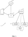
- FIG. 1 illustrates a block diagram of a system 10 that may be employed to accomplish the basic operations described above in accordance with an example embodiment.
- certain tasks like grass cutting, chemical application, visual monitoring and/or the like may be performed by a robot or robotic rover 15. Because the system could operate without the robotic rover 15, the robotic rover 15 is shown in dashed lines in FIG. 1 . Robots or other devices could also be engaged to perform certain other yard maintenance tasks such as raking, fertilizing, lighting, wildlife dispersion and/or the like.
- sprinkler heads and/or a watering computer that interfaces therewith.
- the sprinkler heads may be attached to hoses and the watering computer may provide a mechanism by which to control the turning on/off of water application at the respective sprinkler head locations by providing a central shut off valve for the hoses.
- the hoses, sprinkler heads and/or watering computer may together form watering equipment 20.
- various sensors may be employed by insertion of such sensors into soil for monitoring soil or other growing conditions (e.g., lighting levels, moisture levels, pH, temperature, video or image data, etc.). These sensors may therefore be understood to take various forms within the system 10. However, generally speaking, the sensors may have connectivity to the system 10 in order to enhance operation of system components on the basis of the soil and/or growing condition information gathered by the sensors. Regardless of the specific configuration or placement paradigm, the various sensors may represent sensor equipment 30, as described above.
- the sensor equipment 30, and in some cases also one or more of the devices that comprise the watering equipment 20, may be in communication with a gateway 40 via wireless connections.
- the gateway 40 may subsequently have wireless connection to an access point (AP) 45, which may be directly or indirectly connectable to a user terminal 50.
- the AP 45 may be a router of a home network of the operator.
- direct connection of the AP 45 to the user terminal 50 may be provided via short range wireless communication methods (e.g., Bluetooth, WiFi and/or the like). Indirect connection of the AP 45 to the user terminal 50 may occur via a network 60.
- the network 60 may be a data network, such as a local area network (LAN), a metropolitan area network (MAN), a wide area network (WAN) (e.g., the internet), a wireless personal area network (WPAN), and/or the like, which may couple devices (e.g., the deployed components) to devices such as processing elements (e.g., personal computers, server computers or the like) and/or databases such as the user terminal 50.
- LAN local area network
- MAN metropolitan area network
- WAN wide area network
- WPAN wireless personal area network
- the link between the user interface 50 and the access point 45 is wireless.
- Communication between the network 60 and other devices of the system 10 may be accomplished by either wireline or wireless communication mechanisms and corresponding communication protocols.
- some or all of the sensors of the sensor equipment 30, the watering equipment 20 and/or the robotic rover 15 may be connected to the user terminal 50 by wire and/or be wireless communication means.
- the robotic rover 15 may act as one or both of a piece of sensor equipment 30 or a piece of watering equipment 20. However, given the ability of the robotic rover 15 to act as either or both of a piece of sensor equipment 30 or a piece of watering equipment 20 and the ability of the robotic rover 15 to perform other tasks (e.g., grass cutting) in combination with or independent of the sensor equipment 30 and the watering equipment 20, the robotic rover 15 is shown separately in FIG. 1 .
- the gateway 40 may be a translation agent configured to interface with any or all of the deployed components via wired or wireless communication. According to the invention the gateway 40 translates between two wireless networks.
- the gateway 40 may include a high performance antenna to enable the gateway 40 to communicate wirelessly with deployed components via an 868 mHz radio link (e.g., a first wireless link).
- 868 mHz radio link e.g., a first wireless link
- the first wireless link, and the components connected thereby may be part of a first network (e.g., a garden network) or deployed component network that extends outdoors. Components internal to the house or business, and extending to and between the user terminal 50 may form a second network.
- the gateway 40 may be a translation agent between the first and second networks.
- the gateway 40 may be an aggregation point and communications center for communications in both networks.
- the gateway 40 may be provided within the home or otherwise indoor environment of the operator, and still wirelessly communicate with the deployed components (via the first wireless link) to translate instructions thereto from the operator, which may be provided via a second wireless link to the AP 45.
- the wireless communications may be secured by employing encryption or other security techniques.
- the gateway 40 may also provide secure cloud data storage through connection to the network 60 (e.g., via the AP 45).
- the first and second wireless links are different wireless links that employ different communication protocols and/or frequencies.
- the gateway 40 may also provide the ability for each of the deployed components to be monitored, controlled, programmed or otherwise interfaced with by an operator using the user terminal 50.
- the user terminal 50 may be configured to execute an application (or app) that is tailored to providing an easy setup and/or easy to use interface for interaction with the gateway 40 (and the corresponding deployed components that are reachable through the gateway 40).
- the user terminal 50 may therefore be a smartphone or other mobile terminal, or a laptop, PC, or other computing/communication device.
- the user terminal 50 may include processing circuitry that is enabled to interface with corresponding processing circuitry of the gateway 40 and/or the deployed components to program, control or otherwise interact with the deployed components in a manner described in greater detail below.
- the interaction between the user terminal 50 and the gateway 40 to facilitate programming of, control of, or interaction with the deployed components may create an interactive and fully connectable garden system for irrigation and/or mowing control/coordination.
- the app that may be executed at the user terminal 50 may be configured for control of any or all of the deployed components on a real time or programmed basis.
- the resulting system may be a holistic and connected automatic garden system.
- the connection to content on the internet via network 60 may allow educational content to be integrated into the system's operation to provide operators with an improved interface and more control over gaining full satisfaction of their gardening experience.
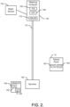
- FIGS. 2 and 3 illustrate a water migration path that may be practiced in connection with an example embodiment.
- some of the components may be removed in simpler example embodiments, and some components may be added to provide more complex architectures in other example embodiments.
- the examples of FIGS. 2 and 3 not provided to be limiting in relation to the components included in the system, but merely to show various examples of some components that may be included in one example system.
- FIG. 3 is merely shown to illustrate one way in which multiple water delivery lines can be provided to service a parcel or yard. The fact that FIG. 3 only shows two water lines is not meant to imply that example embodiments may only work with two lines. To the contrary, example embodiments may be practiced with any number of lines, and with separate and/or different water sources.
- a water source 100 may be used to charge a first water line 110 via a watering computer 120.
- the water source 100 may also charge a second water line 1 12 via a second watering computer 122.
- the first and second water lines 110 and 112 may each be a flexible water hose or garden hose.
- the first and second watering computers 120 and 122 may each be one of the deployed components that forms one component of the watering equipment 20 of FIG. 1 .
- the first and second watering computers 120 and 122 may be directly attached to the water source 100 such that the water source 100 is a tap or spigot to which the pressurized water supply of a house or other structure is supplied.
- a hose or other connector may be provided between the first and second watering computers 120 and 122 and the water source 100.
- An example of such other connector is shown in FIG. 3 , which illustrates an example in which a splitter 125 is provided to split water between the first and second watering computers 120 and 122 and the first and second water lines 110 and 112 that may otherwise be identical or similar to each other in their makeup and operation.
- one or more sprinklers may receive water from the first water line 110 and second water line 112, respectively.
- the first water line 110 may be selectively charged under control of the first watering computer 120 to provide water for spraying from the first sprinkler 130.
- the second water line 112 may be selectively charged under control of the second watering computer 122 to provide water for spraying from the second sprinkler 132.
- the first sprinklers 130 may be provided with pressurized water that is distributed therethough, and the second sprinkler 132 may be similarly provided with water responsive to operation of the second watering computer 122.
- the first and second sprinklers 130 and 132 may typically be components that are not provided with any local intelligence. Instead, the first and second sprinklers 130 and 132 may only be controllable via operation of the first and second watering computers 120 and 122, respectively, to turn on and off watering functions. However, it is possible that the first and second sprinklers 130 and 132 could have intelligent components and/or control aspects provided therein in some cases.
- One or more sensors may also be provided at various locations in the parcel that is served by the sprinklers to detect or sense conditions proximate to the corresponding sensors.
- the first and second sensors 140 and 142 may each correspond to a respective one of the first and second sprinklers 130 and 132, and the app at the user terminal 50 may be configured to note such correspondence so that information received from a respective one of the first or second sensor 140 or 142 can be correlated to actions that may be ordered to the first watering computer 120 or the second watering computer 122, if needed, based on the information.
- some of the deployed components may include a power supply (P/S) 150 that is local to the corresponding ones of the deployed components.
- the P/S 150 f each component may be a battery or battery pack.
- Each powered one of the deployed components may also include communication circuitry (C/C) 160 that includes processing circuitry for controlling each respective component and an antenna for enabling the deployed components to communicate with the gateway 40 via the first wireless link (or alternatively via a wired connection).
- the robotic rover 15 may also be an example of the deployed components, and thus the robotic rover 15 may also include the P/S 150 and the C/C 160.
- the various power supply and communication circuitry components may have different scale, structure and configuration features.
- the first and second watering computers 120 and 122 may each further include a valve 170, which may be operated to respectively isolate and operably couple the water source 100 from/to the first water line 110 and/or the second water line 122, respectively.
- the valve 170 may be operated based on instructions received through the gateway 40 or based on schedule information stored or otherwise accessible via the C/C 160 of the first or second watering computers 120 or 122.
- the first and second watering computers 120 and 122 may provide convenience to operation of the system 10 since the first and second watering computers 120 and 122 can be controlled from anywhere and/or at anytime via the app at the user terminal 50 by programming a schedule or manually directing operation of the first and second watering computers 120 and 122 at the user terminal 50.
- the app can also be used to program the watering computer 120 for automatic operation of the valves 170 based on sensor data received from the first or second sensor 140 or 142.
- the C/C 160 may include processing circuitry 210, as shown in FIG. 4 .
- the processing circuitry 210 that may be configured to perform data processing, control function execution and/or other processing and management services according to an example embodiment of the present invention.
- the processing circuitry 210 may be embodied as a chip or chip set.
- the processing circuitry 210 may comprise one or more physical packages (e.g., chips) including materials, components and/or wires on a structural assembly (e.g., a baseboard).
- the structural assembly may provide physical strength, conservation of size, and/or limitation of electrical interaction for component circuitry included thereon.
- the processing circuitry 210 may therefore, in some cases, be configured to implement an embodiment of the present invention on a single chip or as a single "system on a chip.” As such, in some cases, a chip or chipset may constitute means for performing one or more operations for providing the functionalities described herein.
- the processing circuitry 210 may include one or more instances of a processor 212 and memory 214 that may be in communication with or otherwise control a device interface 220.
- the processing circuitry 210 may be embodied as a circuit chip (e.g., an integrated circuit chip) configured (e.g., with hardware, software or a combination of hardware and software) to perform operations described herein.
- the processing circuitry 210 may communicate with internal electronic components of the first and second watering computers 120 and 122, the first or second sensors 140 and 142 and/or the robotic rover 15, and enable communication externally with other components.
- the device interface 220 may include one or more interface mechanisms for enabling communication with other devices via the gateway 40.
- the device interface 220 may be any means such as a device or circuitry embodied in either hardware, or a combination of hardware and software that is configured to receive and/or transmit data from/to the gateway 40 by virtue of the device interface 220 being capable of sending and receiving messages via the gateway 40.
- the device interface 220 may provide interfaces for communication of components of or external to the system 10 via the gateway 40.
- the device interface 220 may further interface with a sensor (e.g., a temperature sensor, a pH sensor, a light sensor, a moisture sensor and/or the like) to obtain sensor data for communication to other devices (e.g., the watering computers). Meanwhile, if the C/C 160 is for a watering computer, the device interface 220 may provide interfaces to other onboard components (e.g., a user interface including lights and a main button as described below).
- a sensor e.g., a temperature sensor, a pH sensor, a light sensor, a moisture sensor and/or the like
- other onboard components e.g., a user interface including lights and a main button as described below.
- the processor 212 may be embodied in a number of different ways.
- the processor 212 may be embodied as various processing means such as one or more of a microprocessor or other processing element, a coprocessor, a controller or various other computing or processing devices including integrated circuits such as, for example, an ASIC (application specific integrated circuit), an FPGA (field programmable gate array), or the like.
- the processor 212 may be configured to execute instructions stored in the memory 214 or otherwise accessible to the processor 212.
- the processor 212 may represent an entity (e.g., physically embodied in circuitry - in the form of processing circuitry 210) capable of performing operations according to embodiments of the present invention while configured accordingly.
- the processor 212 when the processor 212 is embodied as an ASIC, FPGA or the like, the processor 212 may be specifically configured hardware for conducting the operations described herein.
- the processor 212 when the processor 212 is embodied as an executor of software instructions, the instructions may specifically configure the processor 212 to perform the operations described herein.
- the processor 212 may be embodied as, include or otherwise control the C/C 160.
- the processor 212 may be said to cause each of the operations described in connection with the C/C 160 (and corresponding distributed component with which the C/C 160 is associated) by directing the C/C 160 to undertake the corresponding functionalities responsive to execution of instructions or algorithms configuring the processor 212 (or processing circuitry 210) accordingly.
- the C/C 160 of the sensors may be configured to detect environmental parameters (e.g., sensor data) and report the sensor data via the first wireless link to the gateway 40 (and ultimately to the app on the user terminal 50 or to storage in the cloud via the network 60).
- the C/C 160 of the sensors may be configured to determine a difference between a prior set of sensor data (e.g., the magnitude of a previous sensor measurement) and the current set of sensor data (e.g., the magnitude of a most recent sensor measurement). The amount of difference may then be used to determine whether or not the sensor will report the current set of sensor data. If the difference is small (e.g., less than a threshold amount) the sensor may not report the new value. However, if the difference is large enough (e.g., larger than the threshold amount), then the sensor may report the new value. As such, the C/C 160 of the sensors may be configured to perform battery conservation techniques relative to reporting of sensor data.
- the C/C 160 of the sensors may also be configured to otherwise report (or make a determination on whether to report based on the criteria discussed above) sensor data on a given schedule or responsive to certain activities or events.
- a trigger event e.g., temporal or action based trigger
- the C/C 160 of the sensor may make a determination of the current sensor data and decide whether or not to report the sensor data.
- the C/C 160 of the watering computers may be configured to control the operation of the valve 170 on the basis of schedule information stored locally in the memory 214 of the C/C 160.
- the C/C 160 of the watering computers may also allow modifications to the schedule, other programming operations, and/or the real-time taking of control over the position of the valve 170.
- the operator may be enabled to remotely monitor current valve 170 position and/or program settings and make modifications to either.
- the C/C 160 of the watering computers may be programmed to water when sensor data falling within or exceeding certain ranges or thresholds is received.
- the watering computers may be configured to open the valve 170 to deliver water to the sprinklers.
- the C/C 160 of the robotic rover 15 may be configured to control the travels and operations of the robotic rover 15. Moreover, the C/C 160 of the robotic rover 15 may allow the gateway 40 to grant user access to modification of the schedule of operations of the robotic rover 15 and/or to take real-time control over various operations of the robotic rover 15.
- the app at the user terminal 50 may be employed to coordinate and/or de-conflict watering schedules and mowing schedules. Additionally or alternatively, if the operator makes a modification to a schedule or takes real-time control of one or more components, the app at the user terminal 50 may provide alerts to indicate that the proposed changes to the schedule or current operations may be problematic, or may prevent the making of such changes.
- an alert may be provided to indicate that the robotic rover 15 should have its operations changed, or the opening of the valve 170 may be delayed.
- the electronic deployed components may further include a reset button 230 provided at a secure portion thereof.
- the reset button 230 may be provided in or near a battery compartment of the corresponding device.
- the reset button 230 may trigger different functionalities through the programming of the processing circuitry 210 for corresponding different situations and/or actuation methods. For example, a short press of the reset button 230 may cause the corresponding device to go into a pairing mode. Once in the pairing mode, the device may be detectable by the gateway 40 and/or other devices for a given period of time.
- the app on the user terminal 50 may be used to detect the device in pairing mode and, once detected, the app may also be used to pair the device to another device (e.g., of the first network - the deployed component network).
- the gateway 40 and the C/C 160 of the corresponding devices may then be capable of communication with each other on a continuous, event driven or scheduled basis via the first wireless link.
- the first sensor 140 may be configured to provide sensor data to the first watering computer 120 (e.g., via the gateway 40).
- the first sensor 140 may be paired with the first watering computer 120 via a setup procedure and communicate thereafter on a schedule or an activity/event driven basis.
- simple replacement or insertion of a battery to power up the device may be an additional or alternative method by which to initiate the pairing mode.
- a long press of the reset button 230 may result in returning the device to factory settings.
- contents of the memory 214 may be cleared or otherwise reset to initial settings or conditions.
- Other functions may also or alternatively be provided.
- some devices may have additional buttons or operable members.
- the first watering computer 120 may have a main button on a housing of the first watering computer 120 as described in greater detail below.
- Communication between the gateway 40 and the sensors or watering computers may occur for pairing purposes and to facilitate the operational activities for which the system 10 is ultimately configured.
- the operator may use the app at the user terminal 50 to connect to the gateway 40 and may be provided with one or more control console or interface screens that provide options for interacting with deployed components and/or for programming the deployed components.
- initial setup of the system may be facilitated by placing individual deployed components (either sequentially or simultaneously) in a pairing mode.
- the deployed components are then discoverable via the first wireless link and can be added to the first network. Once added to the first network, the deployed components are considered to be assets of the first network that can be interacted with/programmed and/or the like.
- the deployed components can then be paired with each other and configured for individual and/or cooperative functional performance.
- the first watering computer 120 may be paired with the second watering computer 122, with the robotic rover 15 and/or the first sensor 140.
- the operator may have options provided (e.g., via the app) to select instructions or scheduling options for intelligent irrigation.
- the first watering computer 120 may therefore be instructed regarding the specific stimuli that may be received from the first sensor 140 to trigger opening the valve 170.
- the first watering computer 120 may be provided with (e.g., in the memory 214) a schedule or listing of event triggers which cause the first watering computer 120 to "ping" or otherwise reach out to the first sensor to initiate communication to receive sensor data. Based on the sensor data received (e.g., if certain threshold parameters are reached or not), the valve 170 may be opened.
- the app on the user terminal 50 may ensure that scheduling of mowing during watering (or vice versa) is not possible. However, given that the operator can take control of the watering computers and/or the robotic rover 15 to initiate operations, the app on the user terminal 50 may further prevent any attempts to initiate operations of watering computers or the robotic rover 15 in real-time when the other is also operating in the same area.
- watering schedules or operations can be coordinated to manage or prevent under-pressure situations.
- the first and second watering computers 120 and 122 are connected to the splitter 125, as shown in FIG. 3 , it may be possible for water pressure to be insufficient to effectively charge both the first water line 110 and the second water line 112 at the same time.
- operations of one may be communicated to the other (e.g., via the gateway 40) so that the second watering computer 122 will not open its valve 170, while the first watering computer 120 is currently engaged in watering operations.
- the deployed components of various example embodiments may be adaptive to various conditions or situations.
- the adaptive nature of the deployed components may be provided as a programmable feature, where the operator can use the user terminal 50 to program specific adaptive behaviors that are adjustable parameters, relationships or responses.
- the programmable feature should be understood to be remotely programmable (i.e., programmable from the app and/or the user terminal 50 remote from the component being programmed) via the gateway 40.
- the adaptive nature of the deployed components may be provided as a default feature.
- the adaptive capabilities of the deployed components may either be dependent upon connectivity (e.g., connectivity dependent) for remote programming, or may be connectivity independent (e.g., default programming that exists or is instituted when there is no connectivity or responsive to a loss of connectivity.
- battery power levels may be communicated to the gateway 40 and signal strength values relating to communication with the sensors and/or watering computers may also be determined at the gateway 40. This information (along with sensor data) may be provided to the app at the user terminal 50 to alert the operator when battery power is low, or signal strengths are low. Battery replacement and/or sensor repositioning may then be undertaken to improve the situation.
- the sensor may also adaptively respond to its surroundings to trigger reports.
- the water computer may attempt to ping the sensor via the gateway 40 to trigger a report of sensor data.
- the sensor may be configured (e.g., via the C/C 160) to determine the amount of change in the requested parameter before deciding whether to respond to the ping.
- a change of at least a specific amount or percentage may be required before the sensor will report sensor data via wireless transmission. Since wireless transmission consumes more power than internal operation (e.g., to determine the amount of change and current sensor data), by saving several transmission cycles when there is little data change, battery life can be substantially extended.
- the last value received may be substituted and communicated to the operator (e.g., via the app).
- the operator can wake up the watering computers and/or sensors by sending a ping or wake up message to either component via the app.
- the wake up message may be used to see if the devices are still reacting and active, or to request specific data from or initiate actions at such components in real time.
- the operator can send a wakeup, or setup signal to have the corresponding device beacon for at least a predetermined amount of time (e.g., three minutes).
- the devices may be positioned and the operator may check the app to see what signal strength is detected by the gateway 40. The operator can therefore position the devices in real time and make sure that the position in which a device is currently located is a good location from the perspective of its ability to communicate with the gateway 40.
- one or more of the deployed components may further include frost warning capability.
- frost warning capability since the watering computers typically have pressurized water proximate to the valve 170, it should be appreciated that freezing of water in the body of the watering computers may be destructive to the valve 170. Accordingly, the C/C 160 of one or more components (especially the watering computers) may be configured to identify situations where there is a potential for frost that may damage the watering computers. In some embodiments, if the temperature reaches a predetermined threshold distance from the freezing point (e.g., 5 degrees C, or 10 degrees F), an alert may be issued (e.g., through the app at the user terminal 50) to warn the operator that the watering computer (and/or sensors) should be brought in to avoid damage.
- a predetermined threshold distance from the freezing point e.g., 5 degrees C, or 10 degrees F
- the predetermined threshold may be a factory setting, or may be set by the operator. However, in either case, the ability to identify a present temperature condition to alert the operator of a possible frost event is another example of how the deployed components may be configured (by operator program or by default) to be adaptive relative to their surroundings and/or circumstances.
- the adaptability of the deployed components relates to the inability to connect to the first network or a loss of connection to the first network.
- the watering schedules could be maintained in the cloud, on the user terminal 50 or elsewhere, in some cases, the watering schedule (or at least a portion thereof) may be stored locally at the watering computers.
- the memory 214 may be configured to record at least the last water schedule information employed.
- the first and second watering computers 120 and 122 may each store at least the information indicative of their respective last watering schedules.
- each of the first and second watering computers 120 and 122 will continue to water on the previously provided schedule.
- the user interface for the system may be largely provided via the user terminal 50.
- the user terminal 50 could be a mobile device (e.g., a smartphone) or a fixed terminal (e.g., a PC).
- the user terminal 50 could also be other devices such as a tablet, laptop and/or the like.
- the user terminal 50 may be configured to provide a simple and intuitive interface for enabling the operator to control operation of the system 10.
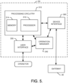
- FIG. 5 illustrates a block diagram of some components of the user terminal 50 that may configure the user terminal to provide the app for control of the system 10.
- the user terminal 50 may include processing circuitry 310, a processor 312, memory 314 and device interface 320 that may be similar in form and/or function to the processing circuitry 210, processor 212, memory 214 and device interface 220 described above. Specific structures, forms and scales of such components may differ. However, the general capabilities may be similar so these components will not be described in detail again in detail. Instead, it should be appreciated that except for changes in specific configuration, content and structure, these components are generally similar. As shown in FIG. 5 , the user terminal 50 includes a user interface 330 and an operation manager 340.
- the user interface 330 may be in communication with the processing circuitry 310 to receive an indication of a user input at the user interface 330 and/or to provide an audible, visual, mechanical or other output to the user.
- the user interface 330 may include, for example, a display (e.g., a touch screen display), one or more buttons or keys (e.g., function buttons or a keyboard), and/or other input/output mechanisms (e.g., microphone, mouse, speakers, cursor, joystick, lights and/or the like).
- the user interface 330 may be configured to provide alerts, warnings and/or notifications to the user or operator responsive to various trigger conditions being detected (e.g., via the sensor equipment 30 or other components).
- System malfunctions, damage or tampering with equipment, equipment theft and other component related stimuli may also be defined as triggers for generation of the alerts, warnings and/or notifications.
- the user interface 330 may be configured to generate such alerts, warnings and/or notifications in response to plant growing conditions being out of specification or out of recommended ranges, or in response to system components having schedule or operational conflicts. Notifications may also be provided regarding general status, current conditions and/or the like.
- the alerts, warnings and/or notifications may be generated via light, sound, visual display, or other devices that may be connected to or part of the operation manager 340.
- the notifications may be provided by text message or email.
- the processing circuitry 310 may be configured to perform data processing, control function execution and/or other processing and management services according to an example embodiment of the present invention.
- the processing circuitry 310 may be configured to control or be embodied as the operation manager 340.
- the operation manager 340 may be configured to receive sensor information from the sensor equipment 30 and/or the watering equipment 20 and make decisions regarding information to be provided to the owner/operator and/or instructions to be provided to the sensor equipment 30 and/or the watering equipment 20.
- the processing circuitry 310 may, in some cases, process the condition information received from the sensor equipment 30 and compare the condition information to growing condition parameters that are stored in the memory 314 for a given zone.
- the memory 314 may be configured to store information, data, applications, instructions or the like for enabling the operation manager 340 to carry out various functions in accordance with exemplary embodiments of the present invention.
- the memory 314 could be configured to buffer input data for processing by the processor 312.
- the memory 314 could be configured to store instructions for execution by the processor 312.
- the memory 314 may include one or more databases that may store a variety of data sets responsive to input from the sensor network.
- applications may be stored for execution by the processor 312 in order to carry out the functionality associated with each respective application.
- the applications may include applications for generation of control consoles for providing options for control of the system.
- the applications may also or alternatively include applications for receiving information regarding component activity/status, environmental parameters, schedule information, device pairing, and/or the like to allow the operation manager 340 to define responses to the information (e.g., based on predefined programming or user input).
- the information/parameters may be entered by the operator, received from deployed components, or may be extracted or retrieved from databases or sources accessible via the internet based on entry of an identity of the plant vegetation in a given zone.
- the operation manager 340 may therefore, for example, provide interface mechanisms for control of the operation of the watering computers.
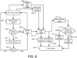
- FIG. 6 illustrates a block diagram of one example of operations that may be facilitated by the operation manager 340 in accordance with an example embodiment.
- the watering computer WC
- the user terminal 50 may present a control console (or series of control consoles) via which the operator can provide instructions to initiate the operations of FIG. 6 .
- An instruction may be provided at operation 400 to open the watering computer's valve (i.e., valve 170).
- a determination may then be made at operation 402 as to whether the robotic rover 15 is active in the area (or at all).
- a warning may be issued at the user interface 330 of the user terminal 50 at operation 404.
- the operator may then determine whether to allow opening of the valve or not at operation 406. If the operator decides not the open the valve, flow returns to the initial state. If the operator decides to allow opening of the valve anyway (e.g., overriding or disregarding the warning), the operator may then be asked to enter a time duration for opening of the valve at operation 408. Of note, the operator may also have the option to cancel to return to the initial state at this time instead of entering the time duration.
- an activation signal may be issued from the user terminal to the watering computer to direct the valve to be opened at operation 410.
- the valve may then remain in an open state until the time duration expires, at which time the valve may close and flow returns to the initial state.
- the operator may also insert instructions to manually close the valve at operation 412.
- a determination may then be made as to whether the manual closure is before or overlaps with a scheduled start time at operation 414. If this manual closure (off schedule) defines an end time that is before the scheduled next start time, the schedule may be maintained at operation 416 and the valve may close at operation 420 so that flow may return to the initial state to be ready for opening again in accordance with the schedule.
- the schedule may be skipped at operation 418 and the valve may close at operation 420 so that flow may return to the initial state to be ready for opening again when the next scheduled opening time arrives.
- the valve may open at operation 410 at the corresponding time, and responsive to time expiring at operation 424, the valve may close.
- the valve may open at operation 410 and then close after a predetermined period of time expires at operation 424 or when the condition clears at operation 428.
- the operator may also manually open or close the valve 170 by operating a local button at the watering computer. If manual (local) operation is performed, the operations described above may still be performed and the times for remaining opening (or a next programmed opening) may again be governed by the schedule information input into the operation manager 340.
- the watering computers may include a limited user interface in the form of a main button provided on a front panel thereof, and a light assembly.
- the light assembly may include three LEDs the LEDs may be capable of expressing red, green and yellow colors in a solid or flashing manner. The LEDs may be useful for providing status information associated with attempts to pair the watering computer with another device, battery status, valve status, and/or the like.
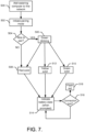
- FIG. 7 illustrates a block diagram of some operations associated with conducting a pairing operation and how information is displayed at the watering computer during such operations.
- the user interface 330 of the user terminal 50 may be employed initially to provide control console options for adding devices to the first network so that they are discovered by the gateway 40 and are recognized by the operation manager 340.
- the watering computer may be added at operation 500.
- the pairing mode e.g., by battery insertion into a deployed component, or by pressing the reset button, or by selection of an option on the user terminal 50
- the watering computer may be discovered by the gateway 40 and the gateway 40 may communicate the identity of the discovered watering computer to the user operation manager 340 so that information indicative of the discovered watering computer can be displayed at the user interface 330.
- a determination is made as to weather pairing is possible at operation 504.
- a green blinking LED lighting output may be provided at operation 506 (at the watering computer).
- the user interface 330 of the user terminal 50 may also or alternatively provide an indication of detection of the watering computer. If the gateway 40 is unable to find the watering computer, a red LED lighting output may be generated at operation 508 for a predetermined time duration (e.g., solid for 20 seconds).
- the LED lighting outputs during the pairing mode may be converted to a signal strength indicator. Again similar indications could also be provided at the user terminal 50. If signal strength is strong (e.g., above a threshold amount), then the LED lighting output may remain green at operation 510. If, the watering computer is moved a sufficient distance away, is shielded from communication with the gateway 40 or otherwise has signal strength fall below the threshold, then the LED lighting output may turn to yellow at operation 512. In both cases, the solid color may be maintained for 20 seconds or some other predetermined time period. However, if the gateway 40 loses contact with the watering computer, flow may proceed to operation 508 from operation 504 and the LED lighting output may again be red.
- the indications regarding signal strength may only be presented for a given period of time (e.g., 20 seconds).
- the LED lighting output may generally be indicative of the battery state of the watering computer at operation 514.
- the battery state may only be provided when a query is received in order to preserve battery life.
- the battery state indication could also indicate that connectivity to the gateway 40 is also still available. As such, connection status may be monitored at operation 516 and, if connectivity is lost, a red flashing LED lighting output may be presented at operation 518.
- battery capacity can be checked remotely or locally at any time.
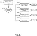
- FIG. 8 illustrates some operations that may be associated with such activity.
- the battery check can be initiated at operation 530 via the operation manager 340 by interacting therewith at the user terminal 50 or via the main button at the watering computer itself. Thereafter, a check is conducted for battery state at the battery pack of the watering computer at operation 532. If battery capacity is estimated to be greater than 4 weeks, the LED lighting output may indicate green (or flash) for twenty seconds at operation 534. If battery capacity is less than 4 weeks, but greater than two weeks, the LED lighting output may indicate yellow by flashing for twenty seconds at operation 536. If battery capacity is less than 2 weeks, the LED lighting output may indicate red by flashing for twenty seconds at operation 538. If the valve is in the off position, the LED lighting output may be solid red (only responsive to a ping) at operation 540.
- the robotic rover 15 may be configured to operate within an area that is defined by a boundary wire or by some other method. The robotic rover 15 then roams within the bounded area to ensure that the entire area is serviced.
- the robotic rover 15 may operate to cut grass on the parcel (i.e., a land lot) or in a zone, the boundaries of which may be defined using one or more physical boundaries (e.g., a fence, wall, curb and/or the like), learned positional boundaries, a boundary wire or combinations thereof.
- the robotic rover 15 may be controlled, at least in part, via control circuitry located onboard.
- the control circuitry may include, among other things, the ability to detect the boundary wire to redirect the robotic rover 15 to other areas within the parcel.
- the control circuitry may also control a positioning module that uses GPS, radio beacon triangulation, odometry or other means to determine location (e.g., its own, or the location of devices encountered).
- the robotic rover 15 may be battery powered via one or more rechargeable batteries. Accordingly, the robotic rover 15 may be configured to return to a charge station that may be located at some position on the parcel in order to recharge the batteries.
- the batteries may power a drive system and a functional control system of the robotic rover 15.
- the control circuitry of the robotic rover 15 may selectively control the application of power or other control signals to the drive system and/or the functional control system to direct the operation of the drive system and/or functional control system. Accordingly, movement and operation of the robotic rover 15 over the parcel may be controlled by the control circuitry in a manner that enables the robotic rover 15 to systematically traverse the parcel while operating to perform a function on the work area of the parcel.
- control circuitry may be configured to communicate wirelessly with the user terminal 50 via the gateway 40 to allow the operator to take control over robotic rover 15 operation via the operation manager 340.
- the operator may be enabled to provide programming instructions remotely through the first and second networks or to take real-time control of one or more aspects of robotic rover 15 operation (e.g., mowing, positioning, etc.).
- the operation manager 340 may be configured to provide interface mechanisms for control of the operation of the watering computers. In some cases, these interface mechanisms may be provided via one or more control consoles or display screens to that allow the operator to interact with data, request data or view data that is retrieved via the gateway 40. As such, the operation manager 340 may interact with components of the second network in order to access the gateway 40, which translates from whatever communication protocols are employed in the second network into the corresponding protocols of the first network (e.g., the garden network) to access information for display at the user terminal 50. However, the operation manager 340 may also interact with the gateway 40 in similar fashion to provide programming instructions to the robotic rover 15, watering computers, sensors and/or the like of the deployed components that are part of the first network.
- the operation manager 340 may also enable real time control or data extraction to be undertaken. Additionally, the operation manager 340 may receive alerts or warnings from the deployed components relating to battery status, signal status, weather-related warnings (e.g., frost warnings), and/or the like.
- alerts or warnings from the deployed components relating to battery status, signal status, weather-related warnings (e.g., frost warnings), and/or the like.
- FIG. 9 which includes FIGS. 9A-9C , illustrates some examples of interface screens or control consoles that may be provided by the operation manager 340 in some embodiments.
- FIG. 9A illustrates a basic start screen showing a home page 600 for the app.
- the app may display a general sensor data section 610, which may display current garden conditions (e.g., temperature, lighting situation, soil moisture, pH, and/or the like).
- the app may also display device status information 620, which may show each device of the first network along with corresponding status information such as, for example, battery status, operational status, and/or the like.
- an option may also be provided for adding new devices in box 630.
- FIG. 9B illustrates an example sensor status screen 650 that may be accessed responsive to selecting the sensor data section 610.
- the sensor status screen 650 may include a current sensor data section 660 that may display current sensor data.
- a historical sensor data section 670 may also be provided to show past data over a given period of time (that may be user selectable).
- a settings adjustment option 680 may also be provided to allow the operator to select various sensor settings.
- the sensor settings may relate to trigger points to trigger the watering computer, pairing activity, signal strength, battery levels, identifying plant types nearby, identifying soil type and/or the like.
- the robotic rover or a watering computer may be selected and similarly controlled to the manner described above for the sensor. That is, after adding the device (e.g., via the new device addition box 630), the device may be paired in a manner described above. The device and its status may then be visible as a selectable device in the device status information 620.
- FIG. 9C illustrates an example device status screen 700 for a watering computer. After pairing, or at any time after the device is added, corresponding settings may be provided for the device. The settings may include an indication of signal strength at 710 (e.g., for placement and setup), options for pairing with a sensor at 720, or options for schedule adjustment (including manual start) at 730.
- the device is the robotic rover 15 and options for selecting a camera view (e.g., in real time) are also be provided.
- the operation manager 340 is further configured to store image data for images captured by the robotic rover 15. In some cases, the operation manager 340 may store such images in a library of images that is selectable and reviewable by the operator via the user terminal 50.
- the C/C 160 of the sensor 140 may be configured with an intelligent measurement cycle.
- the intelligent measurement cycle may be adaptable based on results of previous measurements.
- the intelligent measurement cycle may be adaptable based on the result of the last measurement and/or of the last measurements of the current situation.
- the time between measurements may be extended for various situations. For example, if soil moisture levels are high, the time between measurements may be increased since moist soil is generally regarded as being good for plants. For drier soil, the time between measurements may be decreased in order to avoid not detecting rain or manual watering.
- a planned irrigation event a soil moisture measurement may be performed regardless of the outcome of a previous measurement. This may ensure that the ground state before the irrigation decision is made is known.
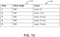
- a plurality of cycle times may be defined for various corresponding moisture content levels or specific humidity ranges.
- a chart such as the chart shown in FIG. 10 may be provided to define corresponding cycle times 800 for different moisture or humidity ranges 810.
- the value ranges are simply listed as TBD to illustrate that any desirable ranges can be input for these values.
- the interface provided by the operation manager 340 may be used to define these values.
- Some corresponding example cycle times 800 are listed, but these are merely exemplary and are not intended to be limiting.
- a mathematical functional relationship between soil moisture and cycle time may be defined instead of a chart. Thus, even more precise adjustment of cycle times may be possible in some cases.
- a system of an example embodiment may include sensor equipment having one or more sensors disposed on a parcel of land, watering equipment disposed on the parcel and configured to selectively apply water to the parcel, and a gateway configured to provide for communication with the sensor equipment and the watering equipment.
- the gateway may interface between a first network and a second network.
- the first network may include at least the watering equipment and the sensor equipment.
- the system may also include a user terminal including processing circuitry configured to provide a remote interface for communication with the sensor equipment and the watering equipment via the gateway.
- the system may further include a robotic rover that is also adaptively configured.
- the watering equipment may include a watering computer including a valve assembly.
- the watering computer may be operably coupled to a water source and a water line such that the valve assembly is operable, by the watering computer, to alternately couple the water source to and isolate the water source from the water line.
- the provide for setup of the sensor equipment and the watering equipment by enabling pairing of the sensor equipment and the watering equipment with each other and the gateway.
- the processing circuitry may be configured to provide an interface for current sensor data and historical sensor data. Alternatively or additionally, the processing circuitry may be configured to provide an interface for adding a new device to the first network and an interface for displaying device status.
- the processing circuitry may be configured to provide an interface for system setup including a display of signal strength of devices of the first network relative to the gateway.
- the processing circuitry may be configured to provide an interface for adjusting a watering schedule of the watering computer.
- the processing circuitry may be configured to enable remote coordination of robotic rover operation with operation of the watering computer.
- the processing circuitry may be configured to provide warnings to the operator based on battery status, schedule conflicts, and weather issues.
- battery status of the watering computer is displayable at the user terminal via the processing circuitry.
- connectivity status of the watering computer may be displayable at the user terminal via the processing circuitry.
Priority Applications (3)
| Application Number | Priority Date | Filing Date | Title |
|---|---|---|---|
| EP21158455.2A EP3841871B1 (en) | 2015-04-10 | 2015-04-10 | Simplified interface and operation in a watering system |
| FIEP21158455.2T FI3841871T3 (fi) | 2015-04-10 | 2015-04-10 | Yksinkertaistettu rajapinta ja toiminta kastelujärjestelmässä |
| EP24162707.4A EP4356724A2 (en) | 2015-04-10 | 2015-04-10 | Simplified interface and operation in a watering system |
Applications Claiming Priority (3)
| Application Number | Priority Date | Filing Date | Title |
|---|---|---|---|
| PCT/EP2015/057846 WO2016162086A1 (en) | 2015-04-10 | 2015-04-10 | Simplified interface and operation in a watering system |
| EP21158455.2A EP3841871B1 (en) | 2015-04-10 | 2015-04-10 | Simplified interface and operation in a watering system |
| EP15716766.9A EP3280251B1 (en) | 2015-04-10 | 2015-04-10 | System comprising watering equipment |
Related Parent Applications (2)
| Application Number | Title | Priority Date | Filing Date |
|---|---|---|---|
| EP15716766.9A Division EP3280251B1 (en) | 2015-04-10 | 2015-04-10 | System comprising watering equipment |
| PCT/EP2015/057846 Previously-Filed-Application WO2016162086A1 (en) | 2015-04-10 | 2015-04-10 | Simplified interface and operation in a watering system |
Related Child Applications (1)
| Application Number | Title | Priority Date | Filing Date |
|---|---|---|---|
| EP24162707.4A Division EP4356724A2 (en) | 2015-04-10 | 2015-04-10 | Simplified interface and operation in a watering system |
Publications (2)
| Publication Number | Publication Date |
|---|---|
| EP3841871A1 EP3841871A1 (en) | 2021-06-30 |
| EP3841871B1 true EP3841871B1 (en) | 2024-03-27 |
Family
ID=52875674
Family Applications (3)
| Application Number | Title | Priority Date | Filing Date |
|---|---|---|---|
| EP24162707.4A Pending EP4356724A2 (en) | 2015-04-10 | 2015-04-10 | Simplified interface and operation in a watering system |
| EP21158455.2A Active EP3841871B1 (en) | 2015-04-10 | 2015-04-10 | Simplified interface and operation in a watering system |
| EP15716766.9A Active EP3280251B1 (en) | 2015-04-10 | 2015-04-10 | System comprising watering equipment |
Family Applications Before (1)
| Application Number | Title | Priority Date | Filing Date |
|---|---|---|---|
| EP24162707.4A Pending EP4356724A2 (en) | 2015-04-10 | 2015-04-10 | Simplified interface and operation in a watering system |
Family Applications After (1)
| Application Number | Title | Priority Date | Filing Date |
|---|---|---|---|
| EP15716766.9A Active EP3280251B1 (en) | 2015-04-10 | 2015-04-10 | System comprising watering equipment |
Country Status (11)
| Country | Link |
|---|---|
| US (2) | US11039582B2 (zh) |
| EP (3) | EP4356724A2 (zh) |
| JP (1) | JP6480599B2 (zh) |
| CN (3) | CN113726908A (zh) |
| AU (3) | AU2015390451B2 (zh) |
| CA (2) | CA2977293C (zh) |
| FI (1) | FI3841871T3 (zh) |
| HU (1) | HUE054635T2 (zh) |
| PL (1) | PL3280251T3 (zh) |
| TW (2) | TWI745766B (zh) |
| WO (1) | WO2016162086A1 (zh) |
Families Citing this family (20)
| Publication number | Priority date | Publication date | Assignee | Title |
|---|---|---|---|---|
| US9468162B2 (en) | 2012-08-01 | 2016-10-18 | Rain Bird Corporation | Irrigation controller wireless network adapter and networked remote service |
| EP2730159B1 (en) | 2012-11-07 | 2019-03-20 | Rain Bird Corporation | Irrigation control system |
| WO2016103066A1 (en) * | 2014-12-23 | 2016-06-30 | Husqvarna Ab | Zone control system for a robotic vehicle |
| WO2016162086A1 (en) | 2015-04-10 | 2016-10-13 | Husqvarna Ab | Simplified interface and operation in a watering system |
| WO2018013964A1 (en) | 2016-07-15 | 2018-01-18 | Rain Bird Corporation | Wireless remote irrigation control |
| WO2018112552A1 (en) * | 2016-12-23 | 2018-06-28 | Ayres Ryan | Apparatus and method for irrigating plants |
| AU2017232031A1 (en) * | 2016-12-23 | 2018-07-12 | Ryan AYRES | Apparatus and Method for Irrigating Plants |
| US10889374B1 (en) * | 2017-05-03 | 2021-01-12 | Survice Engineering Company | Onboard drone human-machine interface for autonomous operation |
| CN107682835B (zh) * | 2017-09-04 | 2020-12-25 | 深圳市瑞科慧联科技有限公司 | 一种分散式决策系统及其决策方法 |
| US10925222B2 (en) * | 2017-11-02 | 2021-02-23 | Larry C. Sarver | Wireless self-powered flow sensor system and ethernet decoder |
| CN108199984A (zh) * | 2018-03-19 | 2018-06-22 | 浙江国自机器人技术有限公司 | 一种云台控制系统、云台网关 |
| DE102018108513A1 (de) | 2018-04-10 | 2019-10-10 | Alfred Kärcher SE & Co. KG | System zur Bewässerung von Grünflächen |
| EP3806617B1 (en) * | 2018-06-15 | 2022-05-25 | Husqvarna Ab | Irrigation computer |
| US11234380B2 (en) | 2018-09-27 | 2022-02-01 | Rain Bird Corporation | Irrigation controller with relays |
| AU2019390300B2 (en) | 2018-11-28 | 2023-12-14 | The Toro Company | Autonomous ground surface treatment system and method of operation of such a system |
| CN110991944B (zh) * | 2019-12-31 | 2023-04-18 | 周浩 | 一种区域化草坪维护管理系统及方法 |
| US11357181B2 (en) | 2020-02-12 | 2022-06-14 | Rain Bird Corporation | Data modulated signal generation in a multi-wire irrigation control system |
| EP3994977A1 (en) | 2020-11-06 | 2022-05-11 | Husqvarna Ab | Watering robot and associated watering system |
| CN113286351B (zh) * | 2021-05-12 | 2022-10-11 | 捷佳润科技集团股份有限公司 | 一种用于智慧农业的无线远程控制终端的通信方法 |
| CA3219284A1 (en) * | 2021-05-17 | 2022-11-24 | Sebastien Eckersley-Maslin | Agricultural system, device and method |
Citations (1)
| Publication number | Priority date | Publication date | Assignee | Title |
|---|---|---|---|---|
| US20140039697A1 (en) * | 2012-08-01 | 2014-02-06 | Rain Bird Corporation | Irrigation controller wireless network adapter and networked remote service |
Family Cites Families (85)
| Publication number | Priority date | Publication date | Assignee | Title |
|---|---|---|---|---|
| US5251153A (en) * | 1988-09-28 | 1993-10-05 | Solatrol, Inc. | Flexibly programmable irrigation system controller |
| JP2764717B2 (ja) * | 1992-09-28 | 1998-06-11 | 株式会社堀場製作所 | 計測システム |
| US6437692B1 (en) * | 1998-06-22 | 2002-08-20 | Statsignal Systems, Inc. | System and method for monitoring and controlling remote devices |
| IL130791A0 (en) * | 1999-07-04 | 2001-01-28 | Arad Com Inc | Irrigation method and system |
| US7103344B2 (en) * | 2000-06-08 | 2006-09-05 | Menard Raymond J | Device with passive receiver |
| US6666384B2 (en) * | 2000-12-04 | 2003-12-23 | Santiago Miguel Prandi | Apparatus and method for applying variable doses of irrigation and agrochemicals |
| JP2002233255A (ja) | 2001-02-07 | 2002-08-20 | Sekisui Plant Systems Co Ltd | 散水システム |
| US6823239B2 (en) * | 2001-11-05 | 2004-11-23 | Rain Master Irrigation Systems, Inc. | Internet-enabled central irrigation control |
| US7146254B1 (en) | 2002-07-05 | 2006-12-05 | Matsushita Electric Works, Ltd. | Systems and methods for optimizing the efficiency of a watering system through use of a computer network |
| US7185045B2 (en) * | 2002-07-15 | 2007-02-27 | Sixnet, Llc | Ethernet interface device for reporting status via common industrial protocols |
| US7010394B1 (en) * | 2002-10-24 | 2006-03-07 | The Toro Company | Intelligent environmental sensor for irrigation systems |
| US7788970B2 (en) * | 2002-10-28 | 2010-09-07 | Digital Sun, Inc. | Wireless sensor probe |
| US7010395B1 (en) * | 2003-01-06 | 2006-03-07 | The Toro Company | PC-programmed irrigation control system |
| US6997642B2 (en) * | 2003-02-12 | 2006-02-14 | Subair Systems, Llc | Golf course environmental management system |
| US7962244B2 (en) * | 2003-04-25 | 2011-06-14 | George Alexanian | Landscape irrigation time of use scheduling |
| US20050125083A1 (en) | 2003-11-10 | 2005-06-09 | Kiko Frederick J. | Automation apparatus and methods |
| KR100677252B1 (ko) * | 2004-09-23 | 2007-02-02 | 엘지전자 주식회사 | 로봇 청소기를 이용한 원격 감시시스템 및 방법 |
| DE102004051438B4 (de) * | 2004-10-22 | 2008-09-25 | Rolf Wilhelm Haupt | Gießwarneinrichtung |
| US20100094472A1 (en) * | 2008-10-14 | 2010-04-15 | Woytowitz Peter J | Irrigation System With Soil Moisture Based Seasonal Watering Adjustment |
| EP2005271A2 (en) * | 2005-10-24 | 2008-12-24 | The Toro Company | Computer-operated landscape irrigation and lighting system |
| US8359288B1 (en) * | 2005-12-30 | 2013-01-22 | Dp Technologies, Inc. | Method and apparatus to utilize sensor, monitor, device (SMD) data based on location |
| US8516087B2 (en) | 2006-02-14 | 2013-08-20 | At&T Intellectual Property I, L.P. | Home automation system and method |
| US7705743B2 (en) * | 2006-03-01 | 2010-04-27 | L-3 Communications Corporation | Self-assembling wireless network, vehicle communications system, railroad wheel and bearing monitoring system and methods therefor |
| US7872593B1 (en) * | 2006-04-28 | 2011-01-18 | At&T Intellectual Property Ii, L.P. | System and method for collecting image data |
| US7949433B2 (en) * | 2006-06-20 | 2011-05-24 | Rain Bird Corporation | Sensor device for interrupting irrigation |
| US9144204B2 (en) * | 2006-06-20 | 2015-09-29 | Rain Bird Corporation | User interface for a sensor-based interface device for interrupting an irrigation controller |
| US20080016436A1 (en) * | 2006-07-14 | 2008-01-17 | Microsoft Corporation | Spreadsheet Interface For Streaming Sensor Data |
| US8055389B2 (en) | 2006-09-01 | 2011-11-08 | Dig Corporation | Method and apparatus for controlling irrigation |
| US20090123340A1 (en) * | 2007-05-04 | 2009-05-14 | H2Observe, Llc | Water quality monitoring device and method |
| ES2311409A1 (es) * | 2007-07-13 | 2009-02-01 | Samcla-Esic, S.L. | Sistema de riego automatizado, remoto y centralizado. |
| WO2009049361A1 (en) * | 2007-10-16 | 2009-04-23 | Aquaspy Group Pty Ltd | Water resource management system and method |
| US20090150002A1 (en) | 2007-12-05 | 2009-06-11 | Daniel Joseph Fekete | Wireless irrigation control server for monitoring and controlling a field module matrix |
| US20090281672A1 (en) * | 2008-02-04 | 2009-11-12 | Reza Pourzia | Weather responsive irrigation systems and methods |
| WO2009114626A2 (en) * | 2008-03-11 | 2009-09-17 | The Regents Of The University Of California | Wireless sensors and applications |
| US8275471B2 (en) * | 2009-11-06 | 2012-09-25 | Adura Technologies, Inc. | Sensor interface for wireless control |
| US9026315B2 (en) * | 2010-10-13 | 2015-05-05 | Deere & Company | Apparatus for machine coordination which maintains line-of-site contact |
| MX2011004330A (es) * | 2008-10-27 | 2011-08-03 | Mueller Int Llc | Sistema y metodo de monitoreo de infraestructura. |
| TWM357196U (en) * | 2008-11-10 | 2009-05-21 | qi-jun Chen | Mobile road-sprinkler |
| WO2010068950A2 (en) * | 2008-12-12 | 2010-06-17 | Blanchard Ron N | Irrigation control apparatus, system, and method |
| US8682494B1 (en) * | 2009-02-02 | 2014-03-25 | Green Badge, LLC | Methods for performing soil measurements including defining antenna configuration based on sensor burial depth |
| US9046461B1 (en) * | 2009-02-03 | 2015-06-02 | Green Badge, LLC | RF amplifier tuning method for coping with expected variations in local dielectric |
| CN101569281B (zh) * | 2009-05-26 | 2013-06-12 | 重庆大学 | 露天植物浇灌控制系统及其控制方法 |
| US8428782B2 (en) | 2009-07-20 | 2013-04-23 | Allure Energy, Inc. | Energy management system and method |
| US20110106320A1 (en) * | 2009-10-30 | 2011-05-05 | Rain Bird Corporation | Method and apparatus for generating an irrigation schedule |
| US8234014B1 (en) * | 2009-11-02 | 2012-07-31 | Eco-Precise Irrigation Controls, LLC | Irrigation control system and method |
| US8285460B2 (en) * | 2010-01-06 | 2012-10-09 | Deere & Company | Varying irrigation scheduling based on height of vegetation |
| US9104211B2 (en) * | 2010-11-19 | 2015-08-11 | Google Inc. | Temperature controller with model-based time to target calculation and display |
| JP5234079B2 (ja) * | 2010-10-01 | 2013-07-10 | オムロン株式会社 | センサ装置、センサ管理システム、センサ装置の制御方法、プログラム及びコンピュータ読み取り可能な記録媒体 |
| CN102035876A (zh) * | 2010-10-15 | 2011-04-27 | 江苏鸿信系统集成有限公司 | 基于m2m架构的农业大棚远程监测和智能控制系统及方法 |
| JP2012147753A (ja) * | 2011-01-21 | 2012-08-09 | Yonden Gijutsu Consultant:Kk | 植物生育施設用自動散水システム |
| US9301460B2 (en) * | 2011-02-25 | 2016-04-05 | The Toro Company | Irrigation controller with weather station |
| US9703275B2 (en) | 2011-06-23 | 2017-07-11 | Rain Bird Corporation | Methods and systems for irrigation and climate control |
| US9212966B2 (en) * | 2011-08-05 | 2015-12-15 | Solon Manufacturing Company | Network manageable advanced gas sensor apparatus and method |
| CN202232421U (zh) | 2011-09-08 | 2012-05-30 | 甘肃大禹节水集团股份有限公司 | 田间滴灌的ZigBee无线控制系统 |
| DE102011084594A1 (de) * | 2011-10-17 | 2013-04-18 | Robert Bosch Gmbh | Autonomes Arbeitsgerät |
| US20130110293A1 (en) * | 2011-10-31 | 2013-05-02 | Harald Illig | Remotely-controlled water sprinkling system and method |
| US8930032B2 (en) * | 2011-11-22 | 2015-01-06 | Zbs Technology, Llc | System and method for wireless irrigation control with a remote application |
| CN102566558B (zh) | 2012-02-21 | 2013-04-10 | 南京农业大学 | 基于Android平台的智能温室管理系统及其方法 |
| US10498623B2 (en) * | 2012-06-27 | 2019-12-03 | Ubiquiti Inc. | Method and apparatus for monitoring and processing sensor data using a sensor-interfacing device |
| TW201430762A (zh) | 2013-01-16 | 2014-08-01 | Tzu-Ping Teng | 分享植物成長照片種植箱及社群網站 |
| ES2659773T3 (es) | 2013-03-15 | 2018-03-19 | Vivint, Inc | Uso de un panel de control como un punto de acceso inalámbrico |
| US20150057817A1 (en) | 2013-07-01 | 2015-02-26 | Skydrop, Llc | Irrigation protocols when connection to a network is lost for an extended period |
| TWI515695B (zh) | 2013-07-05 | 2016-01-01 | 台達電子工業股份有限公司 | 狀態監控系統 |
| US9804604B2 (en) | 2013-08-16 | 2017-10-31 | Husqvarna Ab | Intelligent grounds management system integrating robotic rover |
| RU2643061C2 (ru) | 2013-08-16 | 2018-01-30 | Хускварна Аб | Интеллектуальная система управления для земельного участка |
| CA2927883A1 (en) * | 2013-10-22 | 2015-04-30 | Koninklijke Philips N.V. | Sensor apparatus and method for monitoring a vital sign of a subject |
| EP2870853A1 (en) * | 2013-11-11 | 2015-05-13 | Honda Research Institute Europe GmbH | Lawn mower with remote control |
| TWM483503U (zh) * | 2014-03-03 | 2014-08-01 | Pu Guo Co Ltd | 遠端農場管理系統 |
| AU2015231169B2 (en) | 2014-03-20 | 2019-04-04 | Melnor, Inc. | Wireless apparatus, system, and method for controlling a valve |
| US10512227B2 (en) * | 2014-08-08 | 2019-12-24 | H2O Flow Pro, Llc | Water flow management systems and methods |
| US10425488B2 (en) * | 2014-08-14 | 2019-09-24 | Husqvarna Ab | Distributed intelligent grounds management system |
| US10609862B2 (en) * | 2014-09-23 | 2020-04-07 | Positec Technology (China) Co., Ltd. | Self-moving robot |
| CN204066350U (zh) * | 2014-09-28 | 2014-12-31 | 厦门万安智能股份有限公司 | 一种向室内提醒室外盆景浇水的云传输系统 |
| EP3236732B1 (en) | 2014-12-23 | 2019-12-11 | Husqvarna AB | Lawn monitoring and maintenance via a robotic vehicle |
| CN107249352A (zh) * | 2014-12-31 | 2017-10-13 | 沃尔玛百货有限公司 | 提供新鲜度信息的系统和方法 |
| US20160198645A1 (en) * | 2015-01-08 | 2016-07-14 | Sean B. Weatherill | Irrigation control systems and methods |
| WO2016162086A1 (en) | 2015-04-10 | 2016-10-13 | Husqvarna Ab | Simplified interface and operation in a watering system |
| KR102398330B1 (ko) * | 2015-06-12 | 2022-05-16 | 엘지전자 주식회사 | 이동 로봇 및 그 제어방법 |
| EP3316673B1 (en) * | 2015-07-02 | 2020-11-04 | EcoRobotix SA | Robot vehicle and method using a robot for an automatic treatment of vegetable organisms |
| US10034421B2 (en) * | 2015-07-24 | 2018-07-31 | Irobot Corporation | Controlling robotic lawnmowers |
| HUE049173T2 (hu) * | 2016-04-08 | 2020-09-28 | Husqvarna Ab | Intelligens öntözõrendszer |
| US20190320602A1 (en) * | 2018-04-23 | 2019-10-24 | Rachio, Inc. | Low power data transmission for sprinkler systems |
| EP3948467B1 (en) * | 2019-03-25 | 2024-04-24 | The Toro Company | Autonomous working machine with computer vision-based monitoring and security system |
| CN110338037A (zh) | 2019-08-09 | 2019-10-18 | 王志军 | 一种园林绿化灌溉供水装置 |
| CN114786471A (zh) * | 2019-12-11 | 2022-07-22 | 胡斯华纳有限公司 | 浇水计划控制系统 |
-
2015
- 2015-04-10 WO PCT/EP2015/057846 patent/WO2016162086A1/en active Application Filing
- 2015-04-10 US US15/565,537 patent/US11039582B2/en active Active
- 2015-04-10 CA CA2977293A patent/CA2977293C/en active Active
- 2015-04-10 PL PL15716766T patent/PL3280251T3/pl unknown
- 2015-04-10 EP EP24162707.4A patent/EP4356724A2/en active Pending
- 2015-04-10 EP EP21158455.2A patent/EP3841871B1/en active Active
- 2015-04-10 CN CN202111095424.7A patent/CN113726908A/zh active Pending
- 2015-04-10 CN CN202111095399.2A patent/CN113676552A/zh active Pending
- 2015-04-10 AU AU2015390451A patent/AU2015390451B2/en active Active
- 2015-04-10 CN CN201580078691.XA patent/CN107534677A/zh active Pending
- 2015-04-10 EP EP15716766.9A patent/EP3280251B1/en active Active
- 2015-04-10 CA CA3047462A patent/CA3047462C/en active Active
- 2015-04-10 HU HUE15716766A patent/HUE054635T2/hu unknown
- 2015-04-10 FI FIEP21158455.2T patent/FI3841871T3/fi active
- 2015-04-10 JP JP2017550894A patent/JP6480599B2/ja active Active
-
2016
- 2016-03-30 TW TW108137765A patent/TWI745766B/zh active
- 2016-03-30 TW TW105110114A patent/TWI678905B/zh active
-
2019
- 2019-06-06 AU AU2019203947A patent/AU2019203947A1/en not_active Abandoned
-
2021
- 2021-04-19 AU AU2021202345A patent/AU2021202345A1/en not_active Abandoned
- 2021-06-18 US US17/351,697 patent/US20210307264A1/en active Pending
Patent Citations (1)
| Publication number | Priority date | Publication date | Assignee | Title |
|---|---|---|---|---|
| US20140039697A1 (en) * | 2012-08-01 | 2014-02-06 | Rain Bird Corporation | Irrigation controller wireless network adapter and networked remote service |
Also Published As
| Publication number | Publication date |
|---|---|
| AU2015390451A1 (en) | 2017-08-31 |
| US11039582B2 (en) | 2021-06-22 |
| EP3280251B1 (en) | 2021-03-10 |
| EP3841871A1 (en) | 2021-06-30 |
| AU2015390451B2 (en) | 2019-03-14 |
| JP6480599B2 (ja) | 2019-03-13 |
| TWI678905B (zh) | 2019-12-01 |
| TW202005350A (zh) | 2020-01-16 |
| HUE054635T2 (hu) | 2021-09-28 |
| WO2016162086A1 (en) | 2016-10-13 |
| TWI745766B (zh) | 2021-11-11 |
| CA3047462C (en) | 2022-04-19 |
| CN113726908A (zh) | 2021-11-30 |
| EP4356724A2 (en) | 2024-04-24 |
| US20210307264A1 (en) | 2021-10-07 |
| JP2018511324A (ja) | 2018-04-26 |
| CN113676552A (zh) | 2021-11-19 |
| US20180084741A1 (en) | 2018-03-29 |
| FI3841871T3 (fi) | 2024-04-24 |
| AU2019203947A1 (en) | 2019-06-27 |
| CA2977293A1 (en) | 2016-10-13 |
| TW201637418A (zh) | 2016-10-16 |
| CA3047462A1 (en) | 2016-10-13 |
| PL3280251T3 (pl) | 2021-08-30 |
| CN107534677A (zh) | 2018-01-02 |
| AU2021202345A1 (en) | 2021-05-13 |
| EP3280251A1 (en) | 2018-02-14 |
| CA2977293C (en) | 2019-08-20 |
Similar Documents
| Publication | Publication Date | Title |
|---|---|---|
| US20210307264A1 (en) | Simplified Interface and Operation in a Watering System | |
| US20210307265A1 (en) | Watering System with Adaptive Components | |
| US11844315B2 (en) | Intelligent watering system | |
| JP2023017061A (ja) | 散水システムにおける簡略化されたインタフェースおよび動作 |
Legal Events
| Date | Code | Title | Description |
|---|---|---|---|
| PUAI | Public reference made under article 153(3) epc to a published international application that has entered the european phase |
Free format text: ORIGINAL CODE: 0009012 |
|
| STAA | Information on the status of an ep patent application or granted ep patent |
Free format text: STATUS: THE APPLICATION HAS BEEN PUBLISHED |
|
| AC | Divisional application: reference to earlier application |
Ref document number: 3280251 Country of ref document: EP Kind code of ref document: P |
|
| AK | Designated contracting states |
Kind code of ref document: A1 Designated state(s): AL AT BE BG CH CY CZ DE DK EE ES FI FR GB GR HR HU IE IS IT LI LT LU LV MC MK MT NL NO PL PT RO RS SE SI SK SM TR |
|
| STAA | Information on the status of an ep patent application or granted ep patent |
Free format text: STATUS: REQUEST FOR EXAMINATION WAS MADE |
|
| 17P | Request for examination filed |
Effective date: 20211029 |
|
| RBV | Designated contracting states (corrected) |
Designated state(s): AL AT BE BG CH CY CZ DE DK EE ES FI FR GB GR HR HU IE IS IT LI LT LU LV MC MK MT NL NO PL PT RO RS SE SI SK SM TR |
|
| STAA | Information on the status of an ep patent application or granted ep patent |
Free format text: STATUS: EXAMINATION IS IN PROGRESS |
|
| 17Q | First examination report despatched |
Effective date: 20230616 |
|
| GRAP | Despatch of communication of intention to grant a patent |
Free format text: ORIGINAL CODE: EPIDOSNIGR1 |
|
| STAA | Information on the status of an ep patent application or granted ep patent |
Free format text: STATUS: GRANT OF PATENT IS INTENDED |
|
| INTG | Intention to grant announced |
Effective date: 20231213 |
|
| GRAS | Grant fee paid |
Free format text: ORIGINAL CODE: EPIDOSNIGR3 |
|
| GRAA | (expected) grant |
Free format text: ORIGINAL CODE: 0009210 |
|
| STAA | Information on the status of an ep patent application or granted ep patent |
Free format text: STATUS: THE PATENT HAS BEEN GRANTED |
|
| P01 | Opt-out of the competence of the unified patent court (upc) registered |
Effective date: 20240123 |
|
| AC | Divisional application: reference to earlier application |
Ref document number: 3280251 Country of ref document: EP Kind code of ref document: P |
|
| AK | Designated contracting states |
Kind code of ref document: B1 Designated state(s): AL AT BE BG CH CY CZ DE DK EE ES FI FR GB GR HR HU IE IS IT LI LT LU LV MC MK MT NL NO PL PT RO RS SE SI SK SM TR |
|
| REG | Reference to a national code |
Ref country code: GB Ref legal event code: FG4D |
|
| REG | Reference to a national code |
Ref country code: CH Ref legal event code: EP |
|
| REG | Reference to a national code |
Ref country code: DE Ref legal event code: R096 Ref document number: 602015088119 Country of ref document: DE |
|
| REG | Reference to a national code |
Ref country code: SE Ref legal event code: TRGR |