EP3840706B1 - Verfahren zur herstellung von inkontinenzwegwerfwindeln - Google Patents
Verfahren zur herstellung von inkontinenzwegwerfwindeln Download PDFInfo
- Publication number
- EP3840706B1 EP3840706B1 EP19756349.7A EP19756349A EP3840706B1 EP 3840706 B1 EP3840706 B1 EP 3840706B1 EP 19756349 A EP19756349 A EP 19756349A EP 3840706 B1 EP3840706 B1 EP 3840706B1
- Authority
- EP
- European Patent Office
- Prior art keywords
- diaper
- web
- material web
- diaper side
- side part
- Prior art date
- Legal status (The legal status is an assumption and is not a legal conclusion. Google has not performed a legal analysis and makes no representation as to the accuracy of the status listed.)
- Active
Links
Images


Classifications
-
- A—HUMAN NECESSITIES
- A61—MEDICAL OR VETERINARY SCIENCE; HYGIENE
- A61F—FILTERS IMPLANTABLE INTO BLOOD VESSELS; PROSTHESES; DEVICES PROVIDING PATENCY TO, OR PREVENTING COLLAPSING OF, TUBULAR STRUCTURES OF THE BODY, e.g. STENTS; ORTHOPAEDIC, NURSING OR CONTRACEPTIVE DEVICES; FOMENTATION; TREATMENT OR PROTECTION OF EYES OR EARS; BANDAGES, DRESSINGS OR ABSORBENT PADS; FIRST-AID KITS
- A61F13/00—Bandages or dressings; Absorbent pads
- A61F13/15—Absorbent pads, e.g. sanitary towels, swabs or tampons for external or internal application to the body; Supporting or fastening means therefor; Tampon applicators
- A61F13/15577—Apparatus or processes for manufacturing
- A61F13/15756—Applying tabs, strips, tapes, loops; Knotting the ends of pads
-
- A—HUMAN NECESSITIES
- A61—MEDICAL OR VETERINARY SCIENCE; HYGIENE
- A61F—FILTERS IMPLANTABLE INTO BLOOD VESSELS; PROSTHESES; DEVICES PROVIDING PATENCY TO, OR PREVENTING COLLAPSING OF, TUBULAR STRUCTURES OF THE BODY, e.g. STENTS; ORTHOPAEDIC, NURSING OR CONTRACEPTIVE DEVICES; FOMENTATION; TREATMENT OR PROTECTION OF EYES OR EARS; BANDAGES, DRESSINGS OR ABSORBENT PADS; FIRST-AID KITS
- A61F13/00—Bandages or dressings; Absorbent pads
- A61F13/15—Absorbent pads, e.g. sanitary towels, swabs or tampons for external or internal application to the body; Supporting or fastening means therefor; Tampon applicators
- A61F13/45—Absorbent pads, e.g. sanitary towels, swabs or tampons for external or internal application to the body; Supporting or fastening means therefor; Tampon applicators characterised by the shape
- A61F13/49—Absorbent pads, e.g. sanitary towels, swabs or tampons for external or internal application to the body; Supporting or fastening means therefor; Tampon applicators characterised by the shape specially adapted to be worn around the waist, e.g. diapers, nappies
- A61F13/49007—Form-fitting, self-adjusting disposable diapers
- A61F13/49009—Form-fitting, self-adjusting disposable diapers with elastic means
- A61F13/49014—Form-fitting, self-adjusting disposable diapers with elastic means the elastic means is located at the side panels
- A61F13/49015—Form-fitting, self-adjusting disposable diapers with elastic means the elastic means is located at the side panels the elastic means being elastic panels
Definitions
- the present invention relates to a method for producing a plurality of open-type disposable incontinence diapers for adults.
- Such disposable incontinence diapers are known and often have a main part consisting of a front area, a back area and a crotch area lying between the legs of a user in the longitudinal direction of the diaper, the main part usually already comprising an absorbent core, and separate diaper side parts attached to both sides of the rear lateral longitudinal edges of the back area, which extend in the transverse direction of the diaper beyond the lateral longitudinal edges of the main part and connect the front area and the back area to one another when the article is worn.
- the diaper side panels are preferably attached directly to the main body, i.e., the chassis of the hygiene article, on both sides using the cut-and-place (slip-cut) process.
- This manufacturing technology allows the diaper side panels to be made from a different material than the main body of the hygiene article.
- the diaper side panels can comprise elastic material at least in some areas, whereas the main body can be made from a substantially non-stretchable material.
- the flat material web can be made of a composite material, with continuous material webs that differ in their properties, such as stretchability or breathability, joined together at their respective longitudinal edges.
- WO2008/036706A1 discloses a method for producing diaper side panels using a single-use diaper side panel web in the transverse direction, which has three differentiable regions in the transverse direction.
- the diaper side panels are produced by separating the diaper side panel web is separated in the transverse direction, in particular in such a way that successively formed diaper side panels are aligned rotated by 180° in the plane.
- WO2011/101773A1 discloses a method for producing hygiene articles, wherein a diaper side panel web that is two-fold in the transverse direction is fed to a main panel web.
- the diaper side panel web is produced in such a way that outer side panel sections are separated from a first prefolded material web and joined in a timed manner to a second prefolded material web.
- the timed joining of the outer side panel sections to the second material web entails a complex process.
- WO96/03952A1 discloses a method for manufacturing a diaper, wherein diaper ear sections consisting of a first and a second ear and a bridge material inserted therebetween are severed from an endless composite material web and attached to the diaper main body such that the bridge material overlaps the diaper main body.
- the bridge material adversely affects the manufacturing costs of the diaper.
- WO96/31180A1 discloses a method for producing a closure system for hygiene articles, wherein a continuous closure material web is attached to two continuous flat material webs such that the closure material web forms the central region of a two-way diaper side panel. Before separation, the two-way diaper side panel must be separated into two single-way diaper side panels by cutting, in particular by meandering through the closure material.
- WO2007/042084A1 discloses a method for producing a diaper with attached diaper side panels comprising elastic regions. For this purpose, an elastic material is applied to a carrier material, and the carrier material is overstretched in certain areas.
- the present invention is based on the object of providing an improved method for producing such or similar disposable incontinence diapers, which can be realized cost-effectively and with advantageous processing technology.
- the method according to the invention enables the cost-effective provision of a diaper side panel web which is two-use in the transverse direction and has elastic material in the transverse direction and which can be reliably separated into diaper side panel sections by separating and singling steps which are advantageous in terms of process technology.
- the single, double or triple use of a respective web refers to its transverse direction, i.e. to a direction orthogonal to the respective longitudinal direction of the web.
- the "utility" factor (one, two, three) refers to the number of segments - such as in the case of the diaper side panel, the number of Diaper side panels - which can be formed or separated from the web in the respective direction.
- first material web and/or the attachment material encompassed by the first material web—by means of which the diaper side sections are attached to the diaper main web edge—is substantially inextensible also offers the advantage of increasing the stability of the joining connection between the diaper main web and the attachment material of the diaper side sections.
- fourth and/or fifth material web and/or the fastener carrier material preferably encompassed by the fourth and/or fifth material web, to which fastener elements are attached is substantially inextensible also facilitates the production of a joining connection between fastener elements and a respective diaper side section.
- the closure carrier material of the fourth and/or fifth material web and/or the attachment material of the first material web preferably comprises or consists of a nonwoven material, such as spunbonded nonwovens, meltblown nonwovens, carded nonwovens, spunlace nonwovens, or through-air bonded carded nonwovens, or combinations thereof.
- Spunbonded nonwovens and/or meltblown nonwoven materials are particularly preferred, in particular laminates of spunbond (S) and meltblown (M) nonwovens or nonwoven layers such as SMS, SSMS, SMMS, SSMMS, or SSMMSS laminates.
- nonwoven material contains at least one formulation component based on a thermoplastic polymer, such as polyethylene PE, polypropylene PP, or polyethylene terephthalate PET, or mixtures thereof.
- a thermoplastic polymer such as polyethylene PE, polypropylene PP, or polyethylene terephthalate PET, or mixtures thereof.
- Nonwoven materials comprising rayon, cellulose, polyamide PA, and mixtures thereof are also conceivable.
- the nonwoven material advantageously has a basis weight of 10 - 70 g/m 2 , more preferably of 20 - 60 g/m 2 , more preferably of 30 - 50 g/m 2 .
- the first and second closure carrier materials comprise or consist of the same material, in particular the same nonwoven material.
- the attachment material and the first and/or second closure carrier materials comprise or consist of the same material, in particular the same nonwoven material.
- the first and second elastic materials comprise or consist of the same material.
- the first and/or second elastic material of the second and/or third material web further preferably comprises or consists of a flat material, in particular of a nonwoven fabric, a film, a textile material, a foam or combinations thereof.
- the first and/or second elastic material comprises or consists of a laminate of two or more of the aforementioned flat materials.
- the first and/or second elastic material can be formed from a composite of elastic components and non-elastic components, in particular from a composite of an elastic film or an elastic nonwoven fabric or an elastic foam or elastic threads such as Lycra or Spandex or elastane threads with a non-elastic and/or stretchable nonwoven fabric or foam.
- the composite can be provided as an elastic material by making the non-elastic component stretchable, thus offering little or no resistance to the elastic stretching of the elastic component.
- Another possibility is to join the components using the so-called stretch-bonding process, known to those skilled in the art, thus joining the elastic component in a pre-stretched state to the inelastic component.
- Ring rolling is the process of overstretching an inherently non-stretchable composite material, such as a nonwoven/film laminate, through excessive deflection between meshing rollers.
- an inherently non-stretchable composite material such as a nonwoven/film laminate
- the previously inherently non-stretchable laminate material offers essentially no resistance to elongation.
- the transversely double-sided diaper side panel has a first axis of symmetry extending in the longitudinal direction of the double-sided diaper side panel. Furthermore, the separation of the double-sided diaper side panel takes place along the first axis of symmetry.
- the third material web edge region of the second material web is joined to the first material web edge region of the first material web
- the fifth material web edge region of the third material web is joined to the second material web edge region of the first material web, such that the first, second and third material webs together form a composite web, wherein the materials of the first, second and third material webs extend endlessly in a longitudinal direction of the composite web, and wherein the composite web has a first composite web edge region and a second composite web edge region
- the seventh material web edge region of the fourth material web is joined to the first composite web edge region of the composite web
- the ninth material web edge region of the fifth material web is joined to the second composite web edge region of the composite web, such that the composite web together with the fourth and fifth material webs form the diaper side panel which is two-way in its transverse direction, wherein the materials of the fourth and fifth material webs extend endlessly in a longitudinal direction of the diaper side panel extend.
- the composite web has a second axis of symmetry running in the longitudinal direction of the composite web.
- the first and second elastic diaper side parts each have at least one closure element.
- the respective closure elements are in particular synchronized and attached by means of application techniques known to the person skilled in the art, such as the cut&place method (slip-cut), in particular to first regions of a first diaper side panel edge and to second regions of a second diaper side panel edge.
- cut&place method slip-cut
- each diaper side panel has exactly one fastening element.
- the fastening elements are typically a tab made of a single- or multi-layer flat material, which, starting from a configuration generally folded inward around a distal longitudinal edge of the diaper side panel in question, can be unfolded into an outwardly folded operating position.
- the fastening carrier material of a respective diaper side panel it is conceivable for the fastening carrier material of a respective diaper side panel to have a functional fastening element ("patch") within the distal region of the diaper side panel.
- each fastening element is equipped with adhesive and/or mechanically adhering areas, layers, or elements, such as hook/loop materials.
- the diaper side panel has exactly one fastening element, it proves advantageous if this fastening element is provided approximately centrally in the longitudinal direction of the diaper side panel and in a distal region of the diaper side panel. Furthermore, it proves advantageous if the respective closure element has a longitudinal extension of between 25% and 75% of the longitudinal extension C of the diaper side panel. Furthermore, the respective closure elements are preferably rectangular in shape when folded in and unfolded. In the manufacturer's inactive configuration, they are preferably folded inward onto themselves.
- the second and third material webs are provided by separating a first material web which is two-use in its transverse direction.
- the fourth and fifth material webs are provided by separating a second material web which is two-use in its transverse direction.
- This separation process can be carried out in a manner known to those skilled in the art "in-line” such that the single-use material webs obtained from the separation process in their transverse direction are then fed directly to the further process for producing the diaper side panel, or "off-line” such that the single-use material webs are brought into a storage form and further processed at a later time or at a spatially distant facility.
- the phrase "separating in the longitudinal direction” or “separating along a longitudinal direction” preferably refers to a separation along a straight separating line running parallel to the longitudinal extent of the web in question.
- Other line shapes are also conceivable, such as curved, bent, bent, wavy, jagged, obtuse-angled, acute-angled, pointed-arched, flat-arched, or irregular, whereby these line shapes produce web edges that are not straight.
- the separation can be complete, i.e., continuous, or discontinuous, as a weakening line, such as through perforation or in the form of material cutouts, with the separation being completed in a subsequent process step.
- the separation is preferably carried out without generating scrap material, but can also result in a small amount of discarded material, for example, for aesthetic reasons.
- Both the separation of webs in the longitudinal direction and the separation of diaper side panel sections from a diaper side panel web in the transverse direction as well as the separation of disposable incontinence diapers in the transverse direction can be carried out by means of different methods known to those skilled in the art, such as cutting, punching, lasering, fluid cutting (for example water jet cutting).
- a preferred embodiment provides that the diaper side sections are designed, in particular, to be single-use in their longitudinal direction.
- a diaper side section comprises precisely one diaper side section of a single disposable incontinence diaper.
- the diaper side sections are designed to be double-ended in their longitudinal direction, wherein the separation of the diaper main web is carried out through the diaper side sections in such a way that a first section of a respective diaper side section forms a rear diaper side part of a first disposable incontinence diaper and a second partial section of the respective diaper side section forms a rear diaper side part of a second disposable incontinence diaper immediately adjacent in a diaper longitudinal direction.
- first and second subsections are preferred and are each essentially of the same design.
- the first and the second elastic diaper side part are folded onto themselves at least one fold line FW1 each, in particular at least two fold lines FW1 each, further in particular at least three fold lines FW1 each extending preferably parallel to the longitudinal direction of the disposable incontinence diaper and are releasably fixed in this configuration.
- Such folding of the diaper side panels proves advantageous, on the one hand, when packaging the disposable incontinence diaper, and on the other hand, when the user puts on the disposable incontinence diaper.
- the folded configuration thus obtained can preferably be fixed by the manufacturer, for example by means of individual joining points, in particular adhesive or welding points, in particular ultrasonic welding points, which can nevertheless be manually released relatively easily, in particular in one go, by the user to unfold the diaper side panels.
- a single fastening element preferably positioned approximately centrally on the diaper side panels in the longitudinal direction of the diaper, proves advantageous, wherein furthermore the joining points then do not engage the folded-in fastening element, but are arranged outside the fastening element in the longitudinal direction of the diaper.
- the folded closure element forms an easily graspable gripping area for unfolding the respective diaper side part.
- the diaper side parts are folded by the manufacturer around at least two, in particular at least three folding lines FW1 running in the diaper longitudinal direction, in particular in a Z-shape, and partial areas of the diaper side parts folded onto one another are defined and limited by these folding lines FW1, and further preferably that a partial area lying outside in the transverse direction is substantially inextensible This particularly improves the grip and unfoldability of both the diaper side panel and the folded-in closure element.
- a partial area adjoining the outer partial area towards the inside is designed to be non-stretchable over at least 40% of its area.
- WO 2017/140604 A1 This ensures that the outer part in the transverse direction of the diaper and the part adjoining it to the inside lie flat against one another over a very large inextensible area (of at least 40% of the area of the latter part), which is therefore free of elastic or elasticizing elements.
- an extension E of a respective non-stretchable region of the partial region adjoining the outer partial region inwards, starting from the outer fold line running in the longitudinal direction of the diaper in the transverse direction of the diaper up to the beginning of a stretchable region is preferably at least 15 mm, in particular at least 20 mm, more particularly at least 25 mm, more preferably at least 30 mm, but preferably at most 100 mm, more preferably at most 85 mm, more preferably at most 70 mm.
- an extension A of the diaper side parts folded upon themselves in the diaper transverse direction beyond the respective rear lateral longitudinal edge and an extension C of the diaper side parts folded upon themselves in the diaper longitudinal direction of the disposable incontinence diaper is dimensioned such that the ratio of the extensions A/C to one another is 0.5 ⁇ A/C ⁇ 1.
- the two-way diaper side panel is folded onto itself on both sides by at least one, in particular by at least two, further in particular by at least three folding lines FW2 parallel to the longitudinal direction of the two-way diaper side panel and is releasably fixed in this configuration.
- the longitudinal folding of the diaper side panel can also be carried out after the separation of the dual-use diaper side panel to form single-use diaper side panels.
- the single-use diaper side panels are folded onto themselves by at least one fold line FW3 or FW4, in particular by at least two fold lines FW3 or FW4, which are parallel to a longitudinal direction of the respective single-use diaper side panel, and are releasably fixed in this configuration.
- An embodiment is also conceivable in which the diaper side panels are folded only after being attached to the main diaper panel.
- the diaper side sections are folded onto the main diaper web, and in particular onto an upper side of the main diaper web.
- the respective fold line around which a diaper side section is folded onto the main diaper web can run within the main diaper web or within the region of the diaper side section extending beyond the main diaper web, i.e. outside the main diaper web.
- the upper side of the main diaper web can be the side of the main diaper web facing away from the body, but in particular the side facing the body.
- the diaper side parts formed by the diaper side sections are folded onto the main diaper part of the incontinence disposable diaper only after the incontinence disposable diaper has been separated.
- the main part is preferably folded inwards by the manufacturer, together with the diaper side parts folded onto itself and/or the diaper side parts folded onto the main part, around a first and a second main part folding line each running in the diaper longitudinal direction, preferably in such a way that the diaper side parts on both sides are folded in the thickness direction, i.e. orthogonal to a line enclosing the diaper longitudinal direction and the diaper transverse direction. plane, in at least partial overlap with one another.
- the main part is folded by the manufacturer together with the diaper side parts folded upon themselves and preferably following the previously described folding around main part folding lines running in the diaper longitudinal direction, additionally preferably around at least one or two main part folding lines running in the diaper transverse direction, to form an inner side, i.e. a side of the main part facing the body in the use state, in such a way that a body-facing side of the main part comes to lie directly or indirectly on itself at least in some areas.
- the individual disposable incontinence diapers are folded around at least one, in particular two fold lines FQ extending in a diaper transverse direction.
- the webs i.e. the first, second, third, fourth and fifth material webs and the composite web, each have web edges on both sides, with a web edge region extending flatly in the direction of the other web edge of the respective web adjoining the web edges.
- these webs are each conveyed along their respective longitudinal direction, preferably parallel to each other, in such a way that the two webs preferably lie flat next to each other.
- the joining of two webs can be carried out by means of joining methods known to those skilled in the art, in particular by thermal welding, ultrasonic welding, sewing, sealing or gluing, wherein the two webs are preferably permanently connected to one another.
- the two webs to be joined can be joined with their edge areas pointing towards the other web, i.e. "butt-to-butt", with or without additional material webs bridging the joint between the two webs.
- a quotient Q1 of the width B1 and the sum of the widths B2 and B3 calculated as: B1/(B2+B3) has a value of 0.2 to 1.5, in particular a value of 0.25 to 1.2, in particular a value of 0.25 to 1.0, in particular a value of 0.3 to 0.9, in particular a value of 0.4 to 0.8 and/or a quotient Q2 of the width B1 and the sum of the widths B4 and B5 calculated as: B1/(B4+B5) has a value of 0.15 to 1.5, in particular a value of 0.2 to 1.2, in particular a value of 0.2 to 1.0, in particular a value of 0.25 to 0.7, in particular a value of 0.3 to 0.5.
- B1 ⁇ (B2+B3) and/or B1 ⁇ (B4+B5) applies.
- the width B2 of the second material web and/or the width B3 of the third material web is preferably 20 - 130 mm, in particular 30 - 120 mm, further in particular 40 - 100 mm.
- the width B4 of the fourth material web and/or the width B5 of the fifth material web is preferably 50 - 200 mm, in particular 60 - 190 mm, further in particular 70 - 180 mm.
- a width B6 of the overlap region of the first material web with the second material web and/or a width B7 of the overlap region of the first material web with the third material web is in each case preferably 3 - 17 mm, more particularly 5 - 15 mm, more particularly 6 - 13 mm.
- a width B11 of the composite sheet is 150 - 400 mm, in particular 170 - 350 mm, further in particular 200 - 300 mm.
- a width B10 of the diaper side panel having two uses in its transverse direction is preferably 300 - 650 mm, in particular 320 - 630 mm, further in particular 340 - 610 mm.
- a quotient Q3 of the width B11 (numerator) and the width B10 (denominator) preferably has a value of 0.25 - 0.8, more particularly 0.3 - 0.75, more particularly 0.4 - 0.7.
- the longitudinal extent of the diaper side part sections which are single-use in their longitudinal direction and/or the diaper side parts which are single-use in the diaper longitudinal direction is each 110 - 170 mm, in particular 120 - 160 mm, further in particular 130 - 150 mm.
- the width B1 of the first material web, the width B2 of the second material web, the width B3 of the third material web, the width B4 of the fourth material web, the width B5 of the fifth material web, the width B11 of the composite web and the width B10 of the diaper side panel which is double-sided in its transverse direction are each measured in mm in the transverse direction of the respective web, i.e. along a transverse extension which runs at an angle of 90° to the longitudinal direction of the respective web, in the flat, unfolded and unstretched state.
- width is to be understood as the maximum extension in the transverse direction of the respective web.
- the respective widths B6, B7, B8 or B9 of the overlapping or joining areas and the widths B2e and B3e of the effective elastic areas of the two-use diaper side panel are measured in the transverse direction of the two-use diaper side panel in the flat, unfolded state.
- Longitudinal or transverse dimensions and widths of the disposable incontinence diaper and/or its first or second elastic diaper side panels are measured in mm in the flat, unfolded, unfolded and unstretched state of the disposable incontinence diaper and/or its first and second elastic diaper side panels, i.e. with regard to the stretching of the elastic diaper side panels in the state of first being picked up by the user, but after the manufacturer's folds of the disposable incontinence diaper and/or its elastic diaper side panels have been fully unfolded.
- the extensions A and C of the first and second elastic diaper side panels are measured in mm in the flat, unfolded and unfolded state of the disposable incontinence diaper, whereby, however, the first or second elastic diaper side panel remains in the folded, unstretched and flat, unfolded state.
- the wording "not stretched” is to be understood as meaning that the unfolding and flat spreading of the elastic diaper side panels without the the tensile forces typically exerted by the user when putting on the disposable incontinence diaper are absorbed, so that the material of the unstretched elastic diaper side panels remains in the relaxed state intended by the manufacturer before use.
- the present invention also encompasses a disposable incontinence diaper manufactured or producible according to any of the above or below embodiments.
- the disposable incontinence diaper is particularly preferably designed as a so-called T-shaped diaper. In particular, no diaper side panels are attached to the front area of the disposable incontinence diaper.
- the main part of the disposable incontinence diaper preferably comprises a topsheet that is at least partially liquid-permeable and a preferably breathable and preferably at least partially liquid-impermeable backsheet, which sandwich the absorbent body.
- the disposable incontinence diaper can have cuff elements on both sides of the body-facing side of the crotch region, each forming a lateral leakage barrier and/or extending along a longitudinal extent of the absorbent body.
- the cuff elements preferably comprise or are formed from a nonwoven material ("cuff fleece"), in particular a hydrophobic nonwoven material.
- the topsheet and/or backsheet and/or cuff fleece preferably extend beyond the contour edges of the absorbent body at least in the transverse direction of the diaper, and preferably also in the longitudinal direction of the diaper, in order to form a corresponding overhang.
- the backsheet and topsheet and/or cuff fleece are preferably connected to one another at least in regions, in particular by known joining methods such as welding, sealing, sewing or gluing.
- the main part in the crotch area has, on both sides adjacent to a respective longitudinal edge of the crotch area, an elastic or elasticized section extending in the longitudinal direction of the disposable incontinence diaper, thus forming an elastic or elasticized leg opening section.
- an elastic or elasticized leg opening section extending in the longitudinal direction of the disposable incontinence diaper, thus forming an elastic or elasticized leg opening section.
- elastic threads (Lycra® or similar) known to those skilled in the art are fixed in a pre-tensioned state to the materials forming the main part, preferably to the top and/or backsheet of the main part, in particular in an area in which the top and/or backsheet and/or cuff fleece form an overhang outside the contour edges of the absorbent body.
- An elastic or elasticized leg opening section can be In one variant, it can also be formed by flat or band-shaped materials such as elastic bands, films, nonwovens or foams.
- the absorbent body is suitable and intended for absorbing and permanently storing body excretions, especially body fluids, especially urine.
- the absorbent body can advantageously contain superabsorbent polymer material (SAP), in particular at 5-100% by weight, preferably at 10-95% by weight, more preferably at 15-90% by weight, and most preferably at 20-80% by weight.
- SAP material can absorb at least 15 times, in particular 20 times, its weight in 0.9% by weight saline solution (measured according to NWSP 242.0.R2(15)).
- the SAP material can, for example, be in particle or fiber form or in sheet or foam form.
- the absorbent body may contain additional materials, such as wood pulp fibers or plastic fibers. It is also conceivable to form the absorbent body by arranging one or more layers of different materials, particularly nonwovens.
- the absorbent body is preferably an integral part of the main part and, in such a case, is permanently connected to the other components of the main part by the manufacturer. In such a case, the absorbent body is preferably permanently connected to a topsheet and/or a backsheet of the main part.
- test device is equipped with software that controls the test cycle and ensures automated recording of the force values.
- the rectangular material section to be tested is ideally 25 mm wide and 60 mm long (the length corresponds to the tensile direction) as a test specimen.
- the test specimen is punched out, for example, from a corresponding elastic component of the disposable incontinence diaper or a respective material web, whereby the tensile direction of the test specimen corresponds to the transverse direction of the disposable incontinence diaper or the transverse direction of the material web.
- the 25 mm wide and 60 mm long (tensile direction) test specimen is clamped in the clamps of a tensile testing machine with a jaw spacing of 40 mm, a preload of 0.05 N is applied, and a cyclic movement (loading and unloading, test speed 500 mm/min) is performed, without a dwell time at the upper reversal point, between L0 (length of the test section at a preload of 0.05 N) and a maximum elongation of 60%.
- the final length L1 is also recorded at 0.05 N.
- a material is considered elastic in the respective direction if the permanent elongation is less than 25%.
- a correspondingly narrower section is used. If a 60 mm long section of the elastic component is not available, a correspondingly shorter section is used, whereby the clamping jaw spacing, and thus the effective length of the test section, may need to be reduced to as little as 15 mm. Ensure that the section is firmly clamped in the clamping jaws.
- test device is equipped with software that controls the test cycle and ensures automated recording of the force values.
- the rectangular material section to be tested is ideally 25 mm wide and 60 mm long (the length corresponds to the tensile direction) as a test specimen.
- the test specimen is punched out, for example, from a corresponding component of the disposable incontinence diaper or a respective material web, whereby the tensile direction of the test specimen corresponds to the transverse direction of the disposable incontinence diaper or the transverse direction of the material web.
- a 25 mm wide and 60 mm long (tensile direction) specimen of the material is clamped into the clamps of a tensile testing machine with a 40 mm jaw spacing under a preload of 0.05 N, and the specimen is stretched to a force of 5 N (loaded, test speed 500 mm/min). If the elongation at a force of 5 N is less than 30%, the material is considered inextensible for the purposes of this invention. If the specimen breaks during the above test before the maximum force of 5 N is reached, the material is also considered “inextensible" in the respective direction for the purposes of this invention.
- a method according to the invention for producing disposable incontinence diapers 17 is described below by way of example.
- the method shown by way of example comprises several steps, i.e. separating, joining, folding and singling steps as well as the application of closure elements, which are each described in more detail in the following figures.
- a material web 2 which has three uses in its transverse direction 25 and which essentially comprises material that is inextensible in its transverse direction 25, namely attachment material or closure carrier material, is separated in its longitudinal direction 24 into three material webs (provided with reference numerals 3, 4 and 5), each of which has one use in its transverse direction, namely the first material web 3, the fourth material web 4 and the fifth material web 5.
- a material web 6 which is two-use in its transverse direction 25 and which comprises elastic material at least in some regions in the transverse direction 25 is separated in a second cutting station S2 in the longitudinal direction into two material webs which are each single-use in their transverse direction, namely the second material web 7 and the third material web 8, wherein the second material web 7 and the third material web 8 are each comprise elastic material at least in regions.
- the material webs are subsequently fed to one another and joined together in such a way that in a first joining station U1 the first material web 3, which essentially comprises (or consists of) joining material, and the second material web 7 and third material web 8, each comprising elastic material at least in regions in the transverse direction 25, are joined together in such a way that they together form a composite web 9, in which the joining material of the first material web 3 is arranged in the transverse direction 25 between the second material web 7 and the third material web 8, in which the joining material of the first material web 3 therefore forms a central region 53 in the transverse direction 25.
- the fourth material web 4 and the fifth material web 5, each comprising (or consisting of) closure carrier material that is essentially inextensible in the transverse direction 25, are joined to the composite web 9, as described in more detail below, such that the composite web 9 is arranged between the fourth material web 4 and the fifth material web 5 in the transverse direction 25, and the composite web 9, together with the fourth material web 4 and the fifth material web 5, forms a diaper side panel 10 that is two-sided in the transverse direction 25.
- closure elements tapes
- closure elements are attached to both sides of the closure carrier material of the two-sided diaper side panel 10.
- the dual-use diaper side panel 10 comprising the closure elements 44 is fed to a folding station F1, in which the dual-use diaper side panel 10 is folded onto itself along its fold lines FW2 50 running on both sides in the longitudinal direction 24.
- the folded configuration thus obtained can preferably be fixed by the manufacturer, for example by individual joining points, in particular adhesive or welding points, in particular ultrasonic welding points, which can nevertheless be manually released relatively easily, in particular in one go, by the user to unfold the diaper side panels formed from the dual-use diaper side panel by means of further method steps described in more detail below, namely cutting, separating and joining steps.
- the double-sided diaper side panel 10 folded upon itself is fed to a cutting station S3 and there, in the central region 53 comprising the attachment material, is separated in the longitudinal direction 24 into two single-sided diaper side panels 13a and 13b in the transverse direction 25.
- the single-sided diaper side panels 13a and 13b are separated in a separating station V1 in the transverse direction 25 into single-sided diaper side panels 14a and 14b, respectively.
- the diaper side panels 14a and 14b are combined with an endless diaper main panel 15 in a joining station U3 and are joined on both sides to the diaper main panel 15, preferably by means of ultrasonic welding and in particular in a synchronized manner.
- the separation of the diaper side panels 14a and 14b and their attachment to The diaper main body web 15 can be produced using the cut-and-place method (slip-cut) known to those skilled in the art, but all other application techniques known to those skilled in the art and suitable for this purpose are also possible.
- the diaper main body web 15, which has diaper side sections on both sides, is fed to a second separating station V2, in which the diaper main body web 15 is severed in the transverse direction 25, forming individual disposable incontinence diapers 17.
- the disposable incontinence diapers 17 can then be fed to further processes, such as additional folding steps and/or packaging.
- the joining of webs in the joining stations U1 and/or U2 and/or U3 is particularly preferably carried out by means of ultrasonic welding in this embodiment, but any other joining method known per se to the person skilled in the art and suitable for the purpose, in particular thermal welding, sewing, sealing or gluing, is also possible.
- the separation of the material webs in the cutting stations S1 and/or S2 and/or S3 can be carried out by means of different methods known to those skilled in the art, such as cutting, punching, lasering, fluid cutting (for example water jet cutting).
- the separation of the diaper side sections 14a and 14b in the separation station V1 and of the disposable incontinence diapers 17 in the separation station V2 can be carried out by means of different methods known per se to those skilled in the art, such as cutting, punching, lasering, fluid cutting (for example water jet cutting).
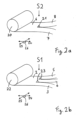
- the Figure 2a shows in a perspective, not to scale, but schematic representation, by way of example, the provision of the second material web 7 and the third material web 8 by separating the two-use material web 6.
- the two-use material web 6 is unwound endlessly from a first roll 20 and conveyed along its longitudinal direction 24.
- the transverse direction 25 of the two-use material web 6 runs orthogonally, i.e. at a right angle 26, to the longitudinal direction 24.
- a cutting device 21 separates the two-use material web 6, which comprises (or consists of) elastic material in the transverse direction 25, into two material webs that are single-use in the transverse direction 25, namely the second material web 7, which comprises or consists of a first elastic material in its transverse direction 25, and the third material web 8, which comprises or consists of a second elastic material in its transverse direction 25.
- the first elastic material is preferably identical to that of the second elastic material, so the first and second elastic materials are preferably made of the same material.
- the second material web 7 and the third material web 8 are preferably approximately the same width in the transverse direction 25, but another variant is conceivable in which the second material web 7 and the third material web 8 are of different widths.
- the Figure 2b shows, in a perspective, not to scale, but schematic representation, by way of example, the provision of the first material web 3, the fourth material web 4 and the fifth material web 5, wherein the first material web 3 comprises (or consists of) attachment material that is essentially inextensible in the transverse direction 25, and wherein the fourth material web 4 comprises or consists of a first closure carrier material that is inextensible in its transverse direction 25, and wherein the fifth material web 5 comprises or consists of a second closure carrier material that is inextensible in its transverse direction 25, by severing a material web 2 that is three-way in the transverse direction 25 and that comprises or consists of material that is essentially inextensible in the transverse direction 25.
- the three-way material web 2 is unwound endlessly from a second roll 22 and conveyed along its longitudinal direction 24.
- the transverse direction 25 of the three-use material web 2 runs orthogonally, i.e. at a right angle 26, to the longitudinal direction 24.
- a cutting device 23 separates the three-use material web 2 into three material webs that are single-use in the transverse direction 25, namely the first material web 3, the fourth material web 4, and the fifth material web 5.
- the first and second closure carrier materials and the attachment material comprise or consist of the same material, in particular of the same nonwoven material.
- At least the fourth material web 4 and the fifth material web 5 are preferably approximately the same width in the transverse direction 25, preferably approximately the same width or each wider than the first material web 3.
- the cutting device 23 is formed by two knives arranged side by side, so that the two cutting processes take place approximately simultaneously. Alternatively, it is conceivable that the knives are arranged offset along the longitudinal direction 24 of the three-use material web 2 such that the two cutting processes take place one after the other. Examples are shown in Figure 2b the material webs are arranged such that the fourth material web 4 is formed from a central region of the three-use material web 2 and the first material web 3 and the fifth material web 5 on both sides of the material web 4 are formed from distal regions of the material web 2. However, any other arrangement of the first material web 3, the fourth material web 4 and the fifth material web 5 along the transverse direction 25 is also conceivable.
- FIGS. 3 a to c show, by way of example, a detailed representation of the arrangement and execution of the process steps for the production of disposable incontinence diapers 17.
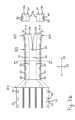
- Figure 3a shows not to scale, but schematically an exemplary embodiment of the attachment steps of the with reference to Figures 2a and 2b referenced first material web 3, second material web 7, third material web 8, fourth material web 4 and fifth material web 5 in plan view.
- the first material web 3 has a first material web edge region 30 and a second material web edge region 31.
- the second material web 7 has a third material web edge region 32 and a fourth material web edge region 33.
- the third material web 8 has a fifth material web edge region 34 and a sixth material web edge region 35.
- the fourth material web 4 has a seventh material web edge region 38 and an eighth material web edge region 39.
- the fifth material web 5 has a ninth material web edge region 40 and a tenth material web edge region 41.
- the first material web 3, which has a width B1 is guided in such a way that it overlaps with the second material web 7, which has a width B2, in such a way that the first material web edge region 30 of the first material web 3 forms an overlap region or joining region with a width B6 with the third material web edge region 32 of the second material web 7, within which the first material web 3 and the second material web 7 are permanently connected to one another in the joining station U1.
- the first material web 3 is guided in such a way that it overlaps with the third material web 8, which has a width B3, in such a way that the second material web edge region 31 of the first material web 3 forms an overlap region or joining region with a width B7 with the fifth material web edge region 34 of the third material web 8, within which the first material web 3 and the third material web 8 are permanently connected to one another in the joining station U1.
- the first material web 3, the second material web 7 and the third material web 8 together form the composite web 9 with a width B11 and a second axis of symmetry 100.
- the composite web 9 further has a first composite web edge region 36 and a second composite web edge region 37.
- the composite web 9 is guided overlapping with the fourth material web 4, which has a width B4, such that the first composite web edge region 36 of the composite web 9 forms an overlapping region or joining region with the seventh material web edge region 38 of the fourth material web 4 with a width B8, within which the composite web 9 and the fourth material web 4 are permanently joined to one another in the joining station U2.
- the composite web 9 is guided with the fifth material web 5, which has a width B5, is guided in an overlapping manner such that the second composite web edge region 37 of the composite web 9 forms an overlapping region or joining region with a width B9 with the ninth material web edge region 40 of the fifth material web 5, within which the composite web 9 and the fifth material web 5 are permanently joined to one another in the joining station U2.
- the composite web 9, the fourth material web 4, and the fifth material web 5 together form the diaper side panel 10, which is two-use in the transverse direction 25, with a width B10 and a first axis of symmetry 101.
- width B1 is 100 mm
- width B2 is 90 mm
- width B3 is 90 mm
- width B1 at 100 mm
- width B1 is smaller than the sum of widths B2 and B3, which is 180 mm.
- the width B4 is 170 mm and the width B5 is 170 mm.
- the width B6 of the overlapping area or joining area formed by the first material web 3 and the second material web 7 has a value of 10 mm.
- the width B7 of the overlapping area or joining area formed by the first material web 3 and the third material web 8 has a value of 10 mm.
- the width B8 of the overlapping area or joining area formed by the composite web 9 and the fourth material web 4 has a value of 10 mm.
- the width B9 of the overlapping area or joining area formed by the composite web 9 and the fifth material web 5 has a value of 10 mm.
- the width B10 of the two-use diaper side panel 10 has a value of 580 mm in this embodiment.
- the width B11 of the composite sheet 9 has a value of 260 mm in this embodiment.
- a quotient Q3 of width 11 (numerator) and width 10 (denominator) has a value of 0.45.
- a distance B2e in the transverse direction 25 of the diaper side panel 10 between the overlapping or joining region formed by the first material web edge region 30 and the third material web edge region 32 and the first composite web edge region 36 and The overlap or joining area formed by the seventh material web edge area 38 is 70 mm in this embodiment.
- a distance B3e in the transverse direction 25 of the diaper side panel 10 between the overlap or joining region formed by the second material web edge region 31 and the fifth material web edge region 34 and the overlap or joining region formed by the second composite web edge region 37 and the ninth material web edge region 40 is 70 mm.
- B2e and B3e therefore denote the widths of the respective effective elastic region of the dual-use diaper side panel 10, since the elastic properties of the materials of the second and third material webs may be impaired in the respective overlap and joining regions.
- the dual-use diaper side panel 10 has a first diaper side panel edge 42 and a second diaper side panel edge 43 and is fed to a taper station T in which the respective closure elements 44 are attached to first regions of the first diaper side panel edge 42 and to second regions of the second diaper side panel edge 43.
- the second material web 7 and the third material web 8 are simultaneously attached to the first material web 3, so that the first material web 3 together with the second material web 7 and the third material web 8 together form the composite web 9. Subsequently, the fourth material web 4 and the fifth material web 5 are again simultaneously attached to the composite web 9. Any other order or combination of the attachment steps is also conceivable and encompassed by the present invention.
- the joining of material web edge regions in the joining stations U1 and/or U2 is particularly preferably carried out by means of ultrasonic welding, but any other joining method known per se to the person skilled in the art and suitable for the purpose, in particular thermal welding, sewing, sealing or gluing, is also possible.
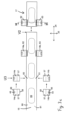
- FIG 3b is not to scale, but schematically and in plan view a preferred embodiment of the folding of the diaper side panel 10, provided with closure elements 44 and two-sided in the transverse direction 25, onto itself and the separating and singling steps for forming the diaper side sections 14a and 14b.
- the two-sided diaper side panel 10 is fed to a folding station F1, in which the two-sided diaper side panel 10 is folded on both sides in a Z-shaped manner around two folding lines FW2 50 running parallel to the longitudinal direction 24 of the two-sided diaper side panel 10. is folded onto itself, forming a diaper side panel 10 which is two-way in the transverse direction 25, provided with closure elements 44 and folded onto itself.
- the first diaper side panel edge 42 and the second diaper side panel edge 43 lie in the transverse direction 25 outside the respective folded-on-self region 51, i.e. outside the region between the two fold lines FW2 50.
- This arrangement is particularly advantageous since a distal gripping region 56 projecting in the transverse direction 25 is formed, which facilitates the gripping and unfolding by the user of the diaper side panels formed from the two-way diaper side panel 10 by means of further method steps described in more detail below.
- the two-use diaper side panel 10 is folded on both sides around two fold lines FW2 50, Z-shaped, onto itself. Further variants are shown in Figures 10b and 10c (but there with reference to the finished disposable incontinence diaper), a single fold line FW2 on each side, for example C-shaped, or at least three fold lines FW2 on each side, for example W-shaped, are conceivable, around which the two-use diaper side panel 10 is folded onto itself.
- the diaper side panel 10, which is double-sided and folded upon itself in the transverse direction 25, is further conveyed to a cutting station S3, in which the double-sided diaper side panel 10 is severed in the longitudinal direction 24 by means of a cutting device 52.
- the separation takes place in the central region 53 of the diaper side panel 10, which comprises the attachment material and is not folded upon itself, in such a way that two diaper side panels 13a and 13b, which are single-sided in the transverse direction 25, are formed.
- the diaper side panels 13a and 13b, which are single-sided in the transverse direction 25, are fed to a separating station V1, in which the single-sided diaper side panels 13a and 13b are severed in the transverse direction 25 in such a way that separated diaper side panels 14a and 14b are formed.
- an area 57 of the diaper side sections 14a or 14b comprising the attachment material is arranged on a longitudinal edge 58 of the diaper side section 14a or 14b opposite the respective gripping area 56.
- the two-use diaper side panel 10 not yet folded around the fold lines FW2 50 comprises Figure 3b in the preferred manner shown by way of example, the closure elements 44.
- an alternative arrangement of the method steps for attaching the closure elements 44 is also conceivable, such as attaching the closure elements 44 to the diaper side panel webs 13a and 13b which are single-use in the transverse direction 25 or to the already separated diaper side panel sections 14a and 14b.
- FIG 3b A preferred variant is shown in which the two-use diaper side panel 10 is first folded onto itself in the folding station F1 and then separated in the cutting station S3 in the longitudinal direction 24 into two single-use diaper side panels 13a and 13b in the transverse direction 25.
- the two-use diaper side panel 10 is separated in a cutting station S4 by means of a cutting device 75 in the central region 53 comprising the attachment material approximately centrally and in the longitudinal direction 24, whereby two single-use diaper side panels 13a and 13b are formed.
- the single-use diaper side panels 13a and 13b are subsequently conveyed to a folding station F2 and there folded onto themselves along two respective folding lines FW3 76 or folding lines FW4 77.
- the diaper side panels 13a and 13b folded upon themselves and single-use in the transverse direction 25 are fed to a separating station V3 in which the single-use diaper side panels 13a and 13b are severed in the transverse direction 25 such that single diaper side panels 14a and 14b are formed.
- the separation of the two-use diaper side panel 10 in the cutting station S4 and/or the separation of the diaper side panel sections 14a and 14b in the separation station V3 can be carried out by means of different methods known per se to the person skilled in the art, such as cutting, punching, lasering, fluid cutting (for example water jet cutting).
- Figure 3c shows, not to scale, but schematically and in plan view, a preferred embodiment of the attachment of diaper side sections 14a and 14b to a diaper main web 15.
- the diaper main web 15 is conveyed to a joining station U3.
- the diaper side sections 14a and 14b, each comprising a closure element 44 are fed to the diaper main web 15 in pairs, preferably in a synchronized manner in the longitudinal direction 24, preferably on both sides and preferably approximately opposite one another in the transverse direction 25.
- the diaper side sections 14a and 14b are arranged in such a way that they each form, at least with a part of the respective region 57 comprising the attachment material, on the longitudinal edge 58 of the respective diaper side section 14a or 14b opposite the gripping region 56, an overlapping or joining region with a first region 60 or a second region 61 of the diaper main part web 15, within which the respective diaper side section 14a or 14b and the diaper main part web 15 are permanently connected to one another in the joining station U3, wherein the diaper side section 14a first elastic diaper side part 62 and the diaper side part section 14b forms the second elastic diaper side part 63.
- the joining of the diaper side sections 14a and 14b to the diaper main part web 15 in the joining station U3 is particularly preferably carried out by means of ultrasonic welding in this embodiment, but any other joining method known per se to the person skilled in the art and suitable for the purpose, in particular thermal welding, sewing, sealing or gluing, is also possible.
- the diaper main part web 15 is fed to a separating station V2 in which the incontinence disposable diapers 17 are separated by separating the diaper main part web 15 in the transverse direction 25.
- the diaper main part web 15 consists of two flat material webs, namely a topsheet web 80 which is at least partially liquid-permeable and a backsheet web 81 which is at least partially liquid-impermeable, between which liquid-absorbing absorbent bodies 69 are inserted in a longitudinally synchronized manner.
- the diaper side part sections 14a and 14b are placed with their regions 57 comprising the attachment material between the topsheet web 80 and the backsheet web 81, as described with reference to Figure 12a described in more detail.
- Figure 12b liquid-impermeable material (cuff fleece) with the function of a lateral leakage barrier, wherein in such a case the first elastic diaper side part 62 and the second elastic diaper side part 63 are placed between the backsheet web 81 and the cuff fleece.
- first elastic diaper side part and the second elastic diaper side part of the disposable incontinence diaper in a thickness direction is also conceivable.
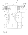
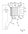
- Figure 5 is not to scale, but schematically and in cross-section a preferred embodiment of a diaper side panel 10 which is two-use in the transverse direction 25.
- the first material web 3, the second material web 7, the third material web 8, the fourth material web 4 and the fifth material web 5 are arranged next to one another in the transverse direction 25 in such a way that the respective directly adjacent material webs with their respective edges pointing in the direction of the nearest material web web edge areas each form an overlapping area or joining area within which the respective webs are permanently connected to one another.
- an upper side 70 of the second material web 7 and the third material web 8, which is facing the body when the disposable incontinence diaper is worn, is connected to an upper side 71 of the first material web 3, the fourth material web 4, and the fifth material web 5, which is facing away from the body.
- any other arrangement of the webs in the thickness direction 27 is also conceivable and is included as a possible embodiment.
- the Figure 6 shows, not to scale, but schematically, a disposable incontinence diaper in the so-called T-shape, designated overall by reference numeral 17.
- the disposable incontinence diaper 17 comprises a main part, designated overall by reference numeral 65, with a body fluid-absorbing absorbent body 69.
- the absorbent body 69 preferably comprises cellulose fibers and superabsorbent polymer particles (SAP).
- SAP superabsorbent polymer particles
- the absorbent body 69 is arranged between two flat materials, namely a liquid-permeable topsheet 80a and a liquid-impermeable backsheet 81a of the diaper main part 65.
- a diaper longitudinal direction 73 and a diaper transverse direction 74 can be distinguished, the latter corresponding to the user's hip circumference direction when the disposable incontinence diaper is worn.
- the main part 65 comprises a front region 82 with front lateral longitudinal edges 83, a back region 64 with a first rear lateral longitudinal edge 66 and a second rear lateral longitudinal edge 67, and a crotch region 84 arranged therebetween. Adjacent to a respective longitudinal edge 85 of the crotch region 84, the main part 65 has an elasticized section 86, thus an elasticized leg opening section.
- These elasticized leg opening sections 86 are formed by elastic threads running between topsheet 80a and backsheet 81a and fixed to topsheet 80a and/or backsheet 81a in a pre-tensioned state, which are curved in an arcuate manner and are therefore oriented at least in sections in the diaper longitudinal direction 73.
- first elastic diaper side part 62 in the back region 64 of the main part 65 in the diaper transverse direction 74, a laterally extending beyond the first rear lateral longitudinal edge 66 and through the diaper side part section 14a (see also Figures 3b and 3c ) formed first elastic diaper side part 62 and a laterally extending beyond the second rear lateral longitudinal edge 67 and through the diaper side part section 14b (see also Figures 3b and 3c ) formed second elastic diaper side part 63 is provided, which are permanently attached to the back region 64 of the main part 65 in an overlapping region 87 in the region of the rear lateral longitudinal edges 66 and 67. In contrast, no diaper side parts are provided in the front region 82.
- the first elastic diaper side part 62 and the second elastic diaper side part 63 each have at least one closure element 44 in the region of their free end 88 in the diaper transverse direction 74.
- the closure element 44 is designed in the form of a preferably rectangular tab and is folded upon itself by the manufacturer. In the use situation, the closure element 44 can be opened, that is to say unfolded again, in order to apply the incontinence disposable diaper 17 to a user, wherein the first elastic diaper side part 62 and the second elastic diaper side part 63 are brought into overlap with the front region 82 of the main part 65 and the closure elements 44 are releasably secured to the side of the front region 82 of the main part 65 facing away from the user (schematically shown in Figure 7 ).
- the first elastic diaper side part 62 and the second elastic diaper side part 63 have a distance D of preferably 5 - 50 mm from a rear transverse edge 79 of the disposable incontinence diaper 17 in the diaper longitudinal direction 73.
- Figure 8 shows a section of the incontinence disposable diaper 17 according to Figure 6 in an enlarged view, specifically in the area of a first elastic diaper side part 62 in a flat, but not stretched, state with two fold lines FW1 68a and 68b.
- the second elastic diaper side panel 63 is merely reversed but otherwise preferably constructed and dimensioned identically. The same applies conversely when the second elastic diaper side panel 63 is described further below.
- the fold lines FW1 68a, 68b correspond to the fold lines FW2 50 of the two-use diaper side panel 10 (cf. Figure 3b ).
- the formation of the diaper side panels as previously described with reference to Figures 1-4 the first elastic diaper side panel 62 comprises three directly adjacent regions in the diaper transverse direction 74, namely a substantially inextensible distal region 90, a substantially inextensible proximal region 93 and an intermediate elastic region 92.
- the distal region 90 of the first elastic diaper side part 62 has the extension B4.1 in the diaper transverse direction 74 (where B4.1 essentially corresponds to the width B4, see Figure 3a , corresponds), comprises substantially inextensible closure carrier material and forms the free end 88 of the first elastic diaper side part 62. Through this distal region 90 runs the fold line FW1 68b closest to the closure element 44 or the free end 88 of the first elastic diaper side part 62 in the diaper longitudinal direction 73.
- the substantially inextensible proximal region 93 has a width B1 approximately half the width of the first material web 3 (see Figure 3a ) corresponding extension B1.1 in the diaper transverse direction 74 and comprises the substantially inextensible attachment material.
- the proximal region 93 overlaps with the diaper main body 65 and is in the overlap or joining region 87 as in Figure 3c illustrated in more detail, inseparably connected to the main diaper part 65.
- the region 92 lying between the distal region 90 and the proximal region 93 and elastic at least in the diaper transverse direction 74 has an extension B2e.1 in the diaper transverse direction 74 (which corresponds to the extension B2e, Figure 3a , corresponds).
- the fold line FW1 68a closest to the main diaper part 65 runs through the elastic region 92 in the diaper longitudinal direction 73.
- an extension E of an inextensible partial region 89 of the partial region 91 extending in the diaper transverse direction 74 between the two fold lines FW1 68a and 68b is 80 mm.
- Figure 9 shows a section of the incontinence disposable diaper 17 according to Figure 6 in an enlarged view, in the area of a second elastic diaper side part 63 with closure element 44 in folded configuration with two fold lines FW1 68, in Z-configuration.
- An extension C of the diaper side part 63 in the diaper longitudinal direction 73 is 140 mm in the illustrated case.
- the folded configuration of the second elastic diaper side panel 63 is releasably fixed in the Z-configuration by joints 94.
- Figure 10a shows a sectional view in section plane III-III from Figure 6
- the cutting plane runs in the transverse direction 74 of the diaper in the back region 64 of a disposable incontinence diaper 17.
- the second elastic diaper side part 63 is placed in the back region 64 of the disposable incontinence diaper 17 between the cover layer 80a (top sheet), which forms the body-facing upper side 70 of the diaper main part 65, and the back layer 81a (back sheet), which forms the body-facing upper side 71 of the diaper main part 65 and which together enclose an absorbent body 69.
- cover layer 80a top sheet
- back layer 81a back sheet
- the second elastic diaper side part 63 is folded onto itself around two fold lines FW1 68, forming a so-called Z-configuration.
- the second elastic diaper side part 63 is folded at the fold line FW1 68a closest to the main part 65 in the flat, spread-out state, i.e., in the unfolded state, in the direction of the upper side 71 facing away from the body, and at the fold line FW1 68b closest to the respective closure element 44 or the free end 88 of the second elastic diaper side part 63 in the flat, spread-out state, i.e., in the unfolded state, in the direction of the upper side 70 of the disposable incontinence diaper 17 facing the body.
- This configuration has proven particularly advantageous when unfolding the diaper side parts by the user.
- the reverse orientation of the folds around the fold lines 68a and 68b is also possible.
- Figure 10b shows a second elastic diaper side part 63 folded onto itself in a W-shape around three fold lines FW1 68, wherein the second elastic diaper side part 63 is folded at the fold line FW1 68a closest to the main part 65 in the flat spread out state, i.e. in the unfolded state, and at the fold line FW1 68b closest to the closure part 44 or the free end 88 of the second elastic diaper side part 63 in the flat spread out state, i.e.
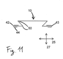
- FIG 11 is not to scale, but schematically a sectional view in section plane II from Figure 3b shown.
- the cutting plane runs in the transverse direction 25 through the two-way diaper side panel 10, which is provided on both sides, i.e. on its first 42 and second diaper side panel edge 43, with a closure element 44 each, and is folded in a Z-shape on both sides around two fold lines FW2 50 running parallel to the longitudinal direction 24.
- the two-way diaper side panel 10 is in Figure 11 shown in a simplified manner, namely without marking the overlapping or joining areas of the webs forming the diaper side panel 10.
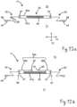
- Figure 12a shows not to scale, but schematically a sectional view in section plane II-II from Figure 3c
- the cutting plane runs in the diaper transverse direction 74 through the back region 64 of the disposable incontinence diaper 17.
- the absorbent body 69 is placed between a backsheet 81a arranged on the side 71 of the disposable incontinence diaper 17 facing away from the body and a topsheet 80a arranged on the side 70 of the disposable incontinence diaper 17 facing the body.
- the first elastic diaper side part 62 and the second elastic diaper side part 63 are each provided with a closure element 44 at their respective free end 88 and are each folded onto themselves in a Z-shape around two fold lines FW1 68.
- the first 62 and the second diaper side part 63 are each arranged between the backsheet 81a arranged on the side 71 of the disposable incontinence diaper 17 facing away from the body and the topsheet 80a arranged on the side 70 of the disposable incontinence diaper 17 facing the body, and are permanently connected to the topsheet and/or the backsheet in the respective overlapping region 87.
- the topsheet 80a is formed entirely from a single flat material.
- FIG 12b An alternative embodiment of a disposable incontinence diaper 17 is shown as a schematic sectional view, not to scale.
- the sectional plane runs in the diaper transverse direction 74 through the disposable incontinence diaper 17.
- the topsheet 80a arranged on the body-facing side of the disposable incontinence diaper 17 is formed from three flat material webs 95, 96a, and 96b.
- the three Flat material webs 95, 96a and 96b are arranged offset from one another in the diaper transverse direction 74 in such a way that the preferably liquid-permeable flat material 95, which is placed centrally in the diaper transverse direction 74, is arranged between a preferably liquid-impermeable first cuff material 96a and a preferably liquid-impermeable second cuff material 96b, wherein the first 96a and the second cuff material 96b each overlap at least in regions with the central flat material 95, and wherein the first 96a and the second cuff material 96b are in particular non-detachably connected to the central flat material 95 in respective joining or overlapping regions.
- the three flat material webs 95, 96a, and 96b forming the topsheet 80a are arranged such that, in the respective joining or overlapping regions, an upper side 70 of the central liquid-permeable flat material 95, which faces the body when the disposable incontinence diaper 17 is worn, is connected to an upper side 71 of the first cuff material 96a and the second cuff material 96b, which faces away from the body.
- the first cuff material 96a and the second cuff material 96b each extend beyond the joining or overlapping region toward the respective other cuff material, specifically such that the projecting free regions 97 of the cuff material can function as a lateral leakage barrier of the disposable incontinence diaper 17.
- first 96a and second cuff material 96b are each provided in the projecting free area 97 in particular with one or more elasticizing means 98, which support the lifting of the first 96a and second cuff material 96b in the worn state and their function as a leakage barrier.
- the liquid-permeable flat material 95 of the topsheet 80a is designed to extend in the diaper transverse direction 74 with approximately the same length as the absorbent body 69, in particular shorter than the backsheet 81a, wherein furthermore in particular the first cuff material 96a extends up to the first rear lateral longitudinal edge 66 and the second cuff material 96b extends up to the second rear lateral longitudinal edge 67 of the disposable incontinence diaper 17.
- first elastic diaper side part 62 and the second elastic diaper side part 63 are preferably placed between the backsheet 81a and the respective first 96a or second cuff material 96b in the thickness direction 27 and are in particular non-detachably connected to them in the respective overlap region 87.
Landscapes
- Health & Medical Sciences (AREA)
- Engineering & Computer Science (AREA)
- Life Sciences & Earth Sciences (AREA)
- Biomedical Technology (AREA)
- Heart & Thoracic Surgery (AREA)
- Vascular Medicine (AREA)
- Epidemiology (AREA)
- Animal Behavior & Ethology (AREA)
- General Health & Medical Sciences (AREA)
- Public Health (AREA)
- Veterinary Medicine (AREA)
- Manufacturing & Machinery (AREA)
- Absorbent Articles And Supports Therefor (AREA)
- Orthopedics, Nursing, And Contraception (AREA)
Applications Claiming Priority (2)
| Application Number | Priority Date | Filing Date | Title |
|---|---|---|---|
| DE102018120495.7A DE102018120495A1 (de) | 2018-08-22 | 2018-08-22 | Verfahren zur Herstellung von Inkontinenzwegwerfwindeln |
| PCT/EP2019/072088 WO2020038860A1 (de) | 2018-08-22 | 2019-08-19 | Verfahren zur herstellung von inkontinenzwegwerfwindeln |
Publications (3)
| Publication Number | Publication Date |
|---|---|
| EP3840706A1 EP3840706A1 (de) | 2021-06-30 |
| EP3840706C0 EP3840706C0 (de) | 2025-03-26 |
| EP3840706B1 true EP3840706B1 (de) | 2025-03-26 |
Family
ID=67704514
Family Applications (1)
| Application Number | Title | Priority Date | Filing Date |
|---|---|---|---|
| EP19756349.7A Active EP3840706B1 (de) | 2018-08-22 | 2019-08-19 | Verfahren zur herstellung von inkontinenzwegwerfwindeln |
Country Status (6)
| Country | Link |
|---|---|
| EP (1) | EP3840706B1 (pl) |
| AU (1) | AU2019324489B2 (pl) |
| DE (1) | DE102018120495A1 (pl) |
| ES (1) | ES3032289T3 (pl) |
| PL (1) | PL3840706T3 (pl) |
| WO (1) | WO2020038860A1 (pl) |
Family Cites Families (9)
| Publication number | Priority date | Publication date | Assignee | Title |
|---|---|---|---|---|
| EP0650714A1 (en) | 1993-11-01 | 1995-05-03 | The Procter & Gamble Company | Method of making an absorbent article using an activatable composite elastic member |
| US5540796A (en) | 1994-08-03 | 1996-07-30 | Kimberly-Clark Corporation | Process for assembling elasticized ear portions |
| US5595618A (en) | 1995-04-03 | 1997-01-21 | Kimberly-Clark Corporation | Assembly process for a laminated tape |
| JP4672649B2 (ja) * | 2004-02-23 | 2011-04-20 | 株式会社瑞光 | 着用物品の製造方法 |
| DE102005048868A1 (de) * | 2005-10-12 | 2007-04-19 | Paul Hartmann Ag | Verfahren zum Herstellen einer Vielzahl von einen Windelhauptteil und daran angefügte vordere und hintere Windelseitenteile aufweisenden Inkontinenzwegwerfwindeln |
| WO2008036706A1 (en) * | 2006-09-20 | 2008-03-27 | Avery Dennison Corporation | Method of making diaper side panels |
| IT1398206B1 (it) * | 2010-02-16 | 2013-02-14 | Fameccanica Data Spa | Procedimento per produrre articoli igienico-sanitari indossabili a guisa di mutandina ed articolo corrispondente. |
| DE102015226814A1 (de) * | 2015-12-29 | 2017-06-29 | Paul Hartmann Ag | Inkontinenzwegwerfwindel |
| DE102016102684A1 (de) * | 2016-02-16 | 2017-08-17 | Paul Hartmann Ag | Inkontinenzwegwerfwindel |
-
2018
- 2018-08-22 DE DE102018120495.7A patent/DE102018120495A1/de not_active Withdrawn
-
2019
- 2019-08-19 AU AU2019324489A patent/AU2019324489B2/en active Active
- 2019-08-19 ES ES19756349T patent/ES3032289T3/es active Active
- 2019-08-19 WO PCT/EP2019/072088 patent/WO2020038860A1/de not_active Ceased
- 2019-08-19 EP EP19756349.7A patent/EP3840706B1/de active Active
- 2019-08-19 PL PL19756349.7T patent/PL3840706T3/pl unknown
Also Published As
| Publication number | Publication date |
|---|---|
| AU2019324489A1 (en) | 2021-04-08 |
| DE102018120495A1 (de) | 2020-02-27 |
| PL3840706T3 (pl) | 2025-07-21 |
| ES3032289T3 (en) | 2025-07-16 |
| AU2019324489B2 (en) | 2025-01-02 |
| EP3840706C0 (de) | 2025-03-26 |
| EP3840706A1 (de) | 2021-06-30 |
| WO2020038860A1 (de) | 2020-02-27 |
Similar Documents
| Publication | Publication Date | Title |
|---|---|---|
| EP2180865B1 (de) | Verfahren zum herstellen von inkontinenzartikeln in höschenform | |
| EP2533741B1 (de) | Inkontinenzartikel in höschenform | |
| EP1933796B1 (de) | Verfahren zum herstellen einer vielzahl von einen windelhauptteil und daran angefügte vordere und hintere windelseitenteile aufweisenden inkontinenzwegwerfwindeln | |
| EP2337541B1 (de) | Absorbierende inkontinenzwegwerfwindel | |
| EP2849695B1 (de) | Inkontinenzartikel in höschenform | |
| EP2241296B1 (de) | Inkontinenzartikel in Höschenform | |
| EP3397225B1 (de) | Inkontinenzwegwerfwindel | |
| DE102008046607A1 (de) | Inkontinenzartikel in Höschenform | |
| EP3416601B1 (de) | Inkontinenzwegwerfwindel | |
| WO2013171066A1 (de) | Inkontinenzartikel in höschenform | |
| EP3397226A1 (de) | Inkontinenzwegwerfwindel | |
| EP3860541A1 (de) | Anordnung von inkontinenzwegwerfwindeln | |
| EP2629727B1 (de) | Verfahren zur herstellung einer inkontinenzwegwerfwindel mit konturierten windelseitenteilen | |
| EP3840706B1 (de) | Verfahren zur herstellung von inkontinenzwegwerfwindeln | |
| EP3886780B1 (de) | Verfahren zur herstellung von inkontinenzwegwerfwindeln | |
| EP3174509B1 (de) | Verfahren zum herstellen von inkontinenzwegwerfwindeln | |
| EP3858310B1 (de) | Inkontinenzwegwerfwindel mit asymmetrischer faltung der hinteren seitenabschnitte | |
| EP3758661A1 (de) | Inkontinenzwegwerfwindel mit elastischer komponente | |
| WO2019166338A1 (de) | Inkontinenzwegwerfwindel mit seitenabschnitten und elastischer komponente | |
| EP3860539A1 (de) | Gefaltete inkontinenzwegwerfwindeln | |
| WO2020069961A1 (de) | Gefaltete inkontinenzwegwerfwindeln | |
| EP3558196A1 (de) | Verfahren zum herstellen von inkontinenzwegwerfwindeln |
Legal Events
| Date | Code | Title | Description |
|---|---|---|---|
| STAA | Information on the status of an ep patent application or granted ep patent |
Free format text: STATUS: UNKNOWN |
|
| STAA | Information on the status of an ep patent application or granted ep patent |
Free format text: STATUS: THE INTERNATIONAL PUBLICATION HAS BEEN MADE |
|
| PUAI | Public reference made under article 153(3) epc to a published international application that has entered the european phase |
Free format text: ORIGINAL CODE: 0009012 |
|
| STAA | Information on the status of an ep patent application or granted ep patent |
Free format text: STATUS: REQUEST FOR EXAMINATION WAS MADE |
|
| 17P | Request for examination filed |
Effective date: 20210318 |
|
| AK | Designated contracting states |
Kind code of ref document: A1 Designated state(s): AL AT BE BG CH CY CZ DE DK EE ES FI FR GB GR HR HU IE IS IT LI LT LU LV MC MK MT NL NO PL PT RO RS SE SI SK SM TR |
|
| DAV | Request for validation of the european patent (deleted) | ||
| DAX | Request for extension of the european patent (deleted) | ||
| GRAP | Despatch of communication of intention to grant a patent |
Free format text: ORIGINAL CODE: EPIDOSNIGR1 |
|
| STAA | Information on the status of an ep patent application or granted ep patent |
Free format text: STATUS: GRANT OF PATENT IS INTENDED |
|
| GRAJ | Information related to disapproval of communication of intention to grant by the applicant or resumption of examination proceedings by the epo deleted |
Free format text: ORIGINAL CODE: EPIDOSDIGR1 |
|
| STAA | Information on the status of an ep patent application or granted ep patent |
Free format text: STATUS: REQUEST FOR EXAMINATION WAS MADE |
|
| GRAP | Despatch of communication of intention to grant a patent |
Free format text: ORIGINAL CODE: EPIDOSNIGR1 |
|
| STAA | Information on the status of an ep patent application or granted ep patent |
Free format text: STATUS: GRANT OF PATENT IS INTENDED |
|
| INTG | Intention to grant announced |
Effective date: 20240912 |
|
| INTC | Intention to grant announced (deleted) | ||
| INTG | Intention to grant announced |
Effective date: 20241014 |
|
| GRAS | Grant fee paid |
Free format text: ORIGINAL CODE: EPIDOSNIGR3 |
|
| GRAA | (expected) grant |
Free format text: ORIGINAL CODE: 0009210 |
|
| STAA | Information on the status of an ep patent application or granted ep patent |
Free format text: STATUS: THE PATENT HAS BEEN GRANTED |
|
| AK | Designated contracting states |
Kind code of ref document: B1 Designated state(s): AL AT BE BG CH CY CZ DE DK EE ES FI FR GB GR HR HU IE IS IT LI LT LU LV MC MK MT NL NO PL PT RO RS SE SI SK SM TR |
|
| REG | Reference to a national code |
Ref country code: GB Ref legal event code: FG4D Free format text: NOT ENGLISH |
|
| REG | Reference to a national code |
Ref country code: CH Ref legal event code: EP |
|
| REG | Reference to a national code |
Ref country code: DE Ref legal event code: R096 Ref document number: 502019013118 Country of ref document: DE |
|
| REG | Reference to a national code |
Ref country code: IE Ref legal event code: FG4D Free format text: LANGUAGE OF EP DOCUMENT: GERMAN |
|
| U01 | Request for unitary effect filed |
Effective date: 20250414 |
|
| U07 | Unitary effect registered |
Designated state(s): AT BE BG DE DK EE FI FR IT LT LU LV MT NL PT RO SE SI Effective date: 20250422 |
|
| PG25 | Lapsed in a contracting state [announced via postgrant information from national office to epo] |
Ref country code: RS Free format text: LAPSE BECAUSE OF FAILURE TO SUBMIT A TRANSLATION OF THE DESCRIPTION OR TO PAY THE FEE WITHIN THE PRESCRIBED TIME-LIMIT Effective date: 20250626 |
|
| PG25 | Lapsed in a contracting state [announced via postgrant information from national office to epo] |
Ref country code: NO Free format text: LAPSE BECAUSE OF FAILURE TO SUBMIT A TRANSLATION OF THE DESCRIPTION OR TO PAY THE FEE WITHIN THE PRESCRIBED TIME-LIMIT Effective date: 20250626 |
|
| PG25 | Lapsed in a contracting state [announced via postgrant information from national office to epo] |
Ref country code: HR Free format text: LAPSE BECAUSE OF FAILURE TO SUBMIT A TRANSLATION OF THE DESCRIPTION OR TO PAY THE FEE WITHIN THE PRESCRIBED TIME-LIMIT Effective date: 20250326 |
|
| REG | Reference to a national code |
Ref country code: ES Ref legal event code: FG2A Ref document number: 3032289 Country of ref document: ES Kind code of ref document: T3 Effective date: 20250716 |
|
| PG25 | Lapsed in a contracting state [announced via postgrant information from national office to epo] |
Ref country code: GR Free format text: LAPSE BECAUSE OF FAILURE TO SUBMIT A TRANSLATION OF THE DESCRIPTION OR TO PAY THE FEE WITHIN THE PRESCRIBED TIME-LIMIT Effective date: 20250627 |
|
| U20 | Renewal fee for the european patent with unitary effect paid |
Year of fee payment: 7 Effective date: 20250826 |
|
| PG25 | Lapsed in a contracting state [announced via postgrant information from national office to epo] |
Ref country code: SM Free format text: LAPSE BECAUSE OF FAILURE TO SUBMIT A TRANSLATION OF THE DESCRIPTION OR TO PAY THE FEE WITHIN THE PRESCRIBED TIME-LIMIT Effective date: 20250326 |
|
| PGFP | Annual fee paid to national office [announced via postgrant information from national office to epo] |
Ref country code: ES Payment date: 20250917 Year of fee payment: 7 |
|
| PGFP | Annual fee paid to national office [announced via postgrant information from national office to epo] |
Ref country code: PL Payment date: 20250811 Year of fee payment: 7 |
|
| PGFP | Annual fee paid to national office [announced via postgrant information from national office to epo] |
Ref country code: GB Payment date: 20250822 Year of fee payment: 7 |
|
| PGFP | Annual fee paid to national office [announced via postgrant information from national office to epo] |
Ref country code: CH Payment date: 20250901 Year of fee payment: 7 |
|
| PGFP | Annual fee paid to national office [announced via postgrant information from national office to epo] |
Ref country code: CZ Payment date: 20250808 Year of fee payment: 7 |
|
| PG25 | Lapsed in a contracting state [announced via postgrant information from national office to epo] |
Ref country code: SK Free format text: LAPSE BECAUSE OF FAILURE TO SUBMIT A TRANSLATION OF THE DESCRIPTION OR TO PAY THE FEE WITHIN THE PRESCRIBED TIME-LIMIT Effective date: 20250326 |
|
| PG25 | Lapsed in a contracting state [announced via postgrant information from national office to epo] |
Ref country code: IS Free format text: LAPSE BECAUSE OF FAILURE TO SUBMIT A TRANSLATION OF THE DESCRIPTION OR TO PAY THE FEE WITHIN THE PRESCRIBED TIME-LIMIT Effective date: 20250726 |
|
| PLBE | No opposition filed within time limit |
Free format text: ORIGINAL CODE: 0009261 |
|
| STAA | Information on the status of an ep patent application or granted ep patent |
Free format text: STATUS: NO OPPOSITION FILED WITHIN TIME LIMIT |
|
| REG | Reference to a national code |
Ref country code: CH Ref legal event code: L10 Free format text: ST27 STATUS EVENT CODE: U-0-0-L10-L00 (AS PROVIDED BY THE NATIONAL OFFICE) Effective date: 20260211 |
|
| 26N | No opposition filed |
Effective date: 20260105 |
|
| PG25 | Lapsed in a contracting state [announced via postgrant information from national office to epo] |
Ref country code: MC Free format text: LAPSE BECAUSE OF FAILURE TO SUBMIT A TRANSLATION OF THE DESCRIPTION OR TO PAY THE FEE WITHIN THE PRESCRIBED TIME-LIMIT Effective date: 20250326 |