EP3840601B1 - Patellaschutzsystem und knieorthese mit solch einem patellaschutzsystem - Google Patents
Patellaschutzsystem und knieorthese mit solch einem patellaschutzsystem Download PDFInfo
- Publication number
- EP3840601B1 EP3840601B1 EP19755389.4A EP19755389A EP3840601B1 EP 3840601 B1 EP3840601 B1 EP 3840601B1 EP 19755389 A EP19755389 A EP 19755389A EP 3840601 B1 EP3840601 B1 EP 3840601B1
- Authority
- EP
- European Patent Office
- Prior art keywords
- protection system
- patella
- patella protection
- designed
- intermediate guard
- Prior art date
- Legal status (The legal status is an assumption and is not a legal conclusion. Google has not performed a legal analysis and makes no representation as to the accuracy of the status listed.)
- Active
Links
Images



Classifications
-
- A—HUMAN NECESSITIES
- A41—WEARING APPAREL
- A41D—OUTERWEAR; PROTECTIVE GARMENTS; ACCESSORIES
- A41D13/00—Professional, industrial or sporting protective garments, e.g. surgeons' gowns or garments protecting against blows or punches
- A41D13/05—Professional, industrial or sporting protective garments, e.g. surgeons' gowns or garments protecting against blows or punches protecting only a particular body part
- A41D13/06—Knee or foot
- A41D13/065—Knee protectors
-
- A—HUMAN NECESSITIES
- A41—WEARING APPAREL
- A41D—OUTERWEAR; PROTECTIVE GARMENTS; ACCESSORIES
- A41D13/00—Professional, industrial or sporting protective garments, e.g. surgeons' gowns or garments protecting against blows or punches
- A41D13/015—Professional, industrial or sporting protective garments, e.g. surgeons' gowns or garments protecting against blows or punches with shock-absorbing means
- A41D13/0153—Professional, industrial or sporting protective garments, e.g. surgeons' gowns or garments protecting against blows or punches with shock-absorbing means having hinged or separable parts
-
- A—HUMAN NECESSITIES
- A41—WEARING APPAREL
- A41D—OUTERWEAR; PROTECTIVE GARMENTS; ACCESSORIES
- A41D13/00—Professional, industrial or sporting protective garments, e.g. surgeons' gowns or garments protecting against blows or punches
- A41D13/015—Professional, industrial or sporting protective garments, e.g. surgeons' gowns or garments protecting against blows or punches with shock-absorbing means
- A41D13/0158—Professional, industrial or sporting protective garments, e.g. surgeons' gowns or garments protecting against blows or punches with shock-absorbing means having ventilation features
-
- A—HUMAN NECESSITIES
- A61—MEDICAL OR VETERINARY SCIENCE; HYGIENE
- A61F—FILTERS IMPLANTABLE INTO BLOOD VESSELS; PROSTHESES; DEVICES PROVIDING PATENCY TO, OR PREVENTING COLLAPSING OF, TUBULAR STRUCTURES OF THE BODY, e.g. STENTS; ORTHOPAEDIC, NURSING OR CONTRACEPTIVE DEVICES; FOMENTATION; TREATMENT OR PROTECTION OF EYES OR EARS; BANDAGES, DRESSINGS OR ABSORBENT PADS; FIRST-AID KITS
- A61F5/00—Orthopaedic methods or devices for non-surgical treatment of bones or joints; Nursing devices ; Anti-rape devices
- A61F5/01—Orthopaedic devices, e.g. long-term immobilising or pressure directing devices for treating broken or deformed bones such as splints, casts or braces
- A61F5/0102—Orthopaedic devices, e.g. long-term immobilising or pressure directing devices for treating broken or deformed bones such as splints, casts or braces specially adapted for correcting deformities of the limbs or for supporting them; Ortheses, e.g. with articulations
- A61F5/0123—Orthopaedic devices, e.g. long-term immobilising or pressure directing devices for treating broken or deformed bones such as splints, casts or braces specially adapted for correcting deformities of the limbs or for supporting them; Ortheses, e.g. with articulations for the knees
-
- A—HUMAN NECESSITIES
- A61—MEDICAL OR VETERINARY SCIENCE; HYGIENE
- A61F—FILTERS IMPLANTABLE INTO BLOOD VESSELS; PROSTHESES; DEVICES PROVIDING PATENCY TO, OR PREVENTING COLLAPSING OF, TUBULAR STRUCTURES OF THE BODY, e.g. STENTS; ORTHOPAEDIC, NURSING OR CONTRACEPTIVE DEVICES; FOMENTATION; TREATMENT OR PROTECTION OF EYES OR EARS; BANDAGES, DRESSINGS OR ABSORBENT PADS; FIRST-AID KITS
- A61F5/00—Orthopaedic methods or devices for non-surgical treatment of bones or joints; Nursing devices ; Anti-rape devices
- A61F5/01—Orthopaedic devices, e.g. long-term immobilising or pressure directing devices for treating broken or deformed bones such as splints, casts or braces
- A61F5/0102—Orthopaedic devices, e.g. long-term immobilising or pressure directing devices for treating broken or deformed bones such as splints, casts or braces specially adapted for correcting deformities of the limbs or for supporting them; Ortheses, e.g. with articulations
- A61F5/0123—Orthopaedic devices, e.g. long-term immobilising or pressure directing devices for treating broken or deformed bones such as splints, casts or braces specially adapted for correcting deformities of the limbs or for supporting them; Ortheses, e.g. with articulations for the knees
- A61F5/0125—Orthopaedic devices, e.g. long-term immobilising or pressure directing devices for treating broken or deformed bones such as splints, casts or braces specially adapted for correcting deformities of the limbs or for supporting them; Ortheses, e.g. with articulations for the knees the device articulating around a single pivot-point
-
- A—HUMAN NECESSITIES
- A61—MEDICAL OR VETERINARY SCIENCE; HYGIENE
- A61F—FILTERS IMPLANTABLE INTO BLOOD VESSELS; PROSTHESES; DEVICES PROVIDING PATENCY TO, OR PREVENTING COLLAPSING OF, TUBULAR STRUCTURES OF THE BODY, e.g. STENTS; ORTHOPAEDIC, NURSING OR CONTRACEPTIVE DEVICES; FOMENTATION; TREATMENT OR PROTECTION OF EYES OR EARS; BANDAGES, DRESSINGS OR ABSORBENT PADS; FIRST-AID KITS
- A61F5/00—Orthopaedic methods or devices for non-surgical treatment of bones or joints; Nursing devices ; Anti-rape devices
- A61F5/01—Orthopaedic devices, e.g. long-term immobilising or pressure directing devices for treating broken or deformed bones such as splints, casts or braces
- A61F5/0102—Orthopaedic devices, e.g. long-term immobilising or pressure directing devices for treating broken or deformed bones such as splints, casts or braces specially adapted for correcting deformities of the limbs or for supporting them; Ortheses, e.g. with articulations
- A61F2005/0132—Additional features of the articulation
- A61F2005/0137—Additional features of the articulation with two parallel pivots
-
- A—HUMAN NECESSITIES
- A61—MEDICAL OR VETERINARY SCIENCE; HYGIENE
- A61F—FILTERS IMPLANTABLE INTO BLOOD VESSELS; PROSTHESES; DEVICES PROVIDING PATENCY TO, OR PREVENTING COLLAPSING OF, TUBULAR STRUCTURES OF THE BODY, e.g. STENTS; ORTHOPAEDIC, NURSING OR CONTRACEPTIVE DEVICES; FOMENTATION; TREATMENT OR PROTECTION OF EYES OR EARS; BANDAGES, DRESSINGS OR ABSORBENT PADS; FIRST-AID KITS
- A61F5/00—Orthopaedic methods or devices for non-surgical treatment of bones or joints; Nursing devices ; Anti-rape devices
- A61F5/01—Orthopaedic devices, e.g. long-term immobilising or pressure directing devices for treating broken or deformed bones such as splints, casts or braces
- A61F5/0102—Orthopaedic devices, e.g. long-term immobilising or pressure directing devices for treating broken or deformed bones such as splints, casts or braces specially adapted for correcting deformities of the limbs or for supporting them; Ortheses, e.g. with articulations
- A61F2005/0132—Additional features of the articulation
- A61F2005/0141—Additional features of the articulation with more than two parallel pivots
-
- A—HUMAN NECESSITIES
- A61—MEDICAL OR VETERINARY SCIENCE; HYGIENE
- A61F—FILTERS IMPLANTABLE INTO BLOOD VESSELS; PROSTHESES; DEVICES PROVIDING PATENCY TO, OR PREVENTING COLLAPSING OF, TUBULAR STRUCTURES OF THE BODY, e.g. STENTS; ORTHOPAEDIC, NURSING OR CONTRACEPTIVE DEVICES; FOMENTATION; TREATMENT OR PROTECTION OF EYES OR EARS; BANDAGES, DRESSINGS OR ABSORBENT PADS; FIRST-AID KITS
- A61F5/00—Orthopaedic methods or devices for non-surgical treatment of bones or joints; Nursing devices ; Anti-rape devices
- A61F5/01—Orthopaedic devices, e.g. long-term immobilising or pressure directing devices for treating broken or deformed bones such as splints, casts or braces
- A61F5/0102—Orthopaedic devices, e.g. long-term immobilising or pressure directing devices for treating broken or deformed bones such as splints, casts or braces specially adapted for correcting deformities of the limbs or for supporting them; Ortheses, e.g. with articulations
- A61F2005/0132—Additional features of the articulation
- A61F2005/0165—Additional features of the articulation with limits of movement
-
- A—HUMAN NECESSITIES
- A61—MEDICAL OR VETERINARY SCIENCE; HYGIENE
- A61F—FILTERS IMPLANTABLE INTO BLOOD VESSELS; PROSTHESES; DEVICES PROVIDING PATENCY TO, OR PREVENTING COLLAPSING OF, TUBULAR STRUCTURES OF THE BODY, e.g. STENTS; ORTHOPAEDIC, NURSING OR CONTRACEPTIVE DEVICES; FOMENTATION; TREATMENT OR PROTECTION OF EYES OR EARS; BANDAGES, DRESSINGS OR ABSORBENT PADS; FIRST-AID KITS
- A61F5/00—Orthopaedic methods or devices for non-surgical treatment of bones or joints; Nursing devices ; Anti-rape devices
- A61F5/01—Orthopaedic devices, e.g. long-term immobilising or pressure directing devices for treating broken or deformed bones such as splints, casts or braces
- A61F5/0102—Orthopaedic devices, e.g. long-term immobilising or pressure directing devices for treating broken or deformed bones such as splints, casts or braces specially adapted for correcting deformities of the limbs or for supporting them; Ortheses, e.g. with articulations
- A61F2005/0132—Additional features of the articulation
- A61F2005/0172—Additional features of the articulation with cushions
- A61F2005/0176—Additional features of the articulation with cushions supporting the patella
-
- A—HUMAN NECESSITIES
- A63—SPORTS; GAMES; AMUSEMENTS
- A63B—APPARATUS FOR PHYSICAL TRAINING, GYMNASTICS, SWIMMING, CLIMBING, OR FENCING; BALL GAMES; TRAINING EQUIPMENT
- A63B71/00—Games or sports accessories not covered in groups A63B1/00 - A63B69/00
- A63B71/08—Body-protectors for players or sportsmen, i.e. body-protecting accessories affording protection of body parts against blows or collisions
- A63B71/12—Body-protectors for players or sportsmen, i.e. body-protecting accessories affording protection of body parts against blows or collisions for the body or the legs, e.g. for the shoulders
- A63B71/1225—Body-protectors for players or sportsmen, i.e. body-protecting accessories affording protection of body parts against blows or collisions for the body or the legs, e.g. for the shoulders for the legs, e.g. thighs, knees, ankles, feet
- A63B2071/125—Body-protectors for players or sportsmen, i.e. body-protecting accessories affording protection of body parts against blows or collisions for the body or the legs, e.g. for the shoulders for the legs, e.g. thighs, knees, ankles, feet for the knee
Definitions
- the present invention relates to a patella protection system designed to be worn by a user.
- the present invention relates to a knee brace designed to be worn by a user and comprising such a patella protection system.
- orthopaedic protection systems are well known and are designed to protect a wearer's body part from injuries, particularly during physical activity.
- braces for protecting the knees of wearers, in particular during motorcycle racing and skiing.
- knee braces are used to limit the movement of the knee joint within a predetermined angular range, thus avoiding ligament tears, hypertension or other injuries.
- braces usually comprise an upper frame member, i.e. the member that is fastened to and protects the upper part of the leg of the wearer, a lower frame member, i.e. the member that is fastened to and protects the lower part of the leg of the wearer, and an intermediate guard member positioned between the upper frame and lower frame members.
- an upper frame member i.e. the member that is fastened to and protects the upper part of the leg of the wearer
- a lower frame member i.e. the member that is fastened to and protects the lower part of the leg of the wearer
- an intermediate guard member positioned between the upper frame and lower frame members.
- the upper and the lower frame members are pivotally connected therebetween and with the intermediate member to allows the brace to move between a straight configuration and an angulated configuration, when the user flexes his/her leg.
- knee braces do not provide an effective and continuous protection of the patella during the movement of the members between the straight configuration and the angulated configuration of the brace.
- knee braces which allow for a more efficient protection of the patella in all the operative configurations.
- US9693887 describes a protective patella guard adapted for use with a knee brace having upper and lower frame members.
- the protective patella guard includes an upper cup element coupled to the upper frame member, a lower cup element coupled to the lower frame member and an intermediate cup member operatively coupled to the upper cup element.
- patella guard All elements of the patella guard are formed by concave cups.
- the patella guard is transitional between a first (straight) configuration and a second (angulated) configuration, wherein the degree of overlap between the upper cup element, the lower cup element and the intermediate cup element decreases as the patella guard transitions from the first configuration to the second configuration.
- a first drawback lies in that the upper and lower cup elements could laterally move or block during configuration transitions, thus preventing the correct functioning of the brace.
- a further drawback concerns the fact that this system does not allow an effective breathability of the user's leg, since the cup elements have a closed wall.
- Another drawback is that the intermediate cup element has a reduced deformability and doesn't allow an efficient absorption of the strikes and blows against the brace.
- a further drawback is that the hinge means of the brace which connect the upper and the lower frame members do not accurately block the rotation thereof within a predetermined angular range.
- An object of the present invention is to provide a patella protection system for use with a knee brace which allow to solve the above mentioned drawbacks.
- an aim of the present invention is to provide a patella protection system which allows the protection of the patella during the movement from a straight configuration to an angulated configuration.
- a further aim of the present invention is to provide a patella protection system which allows movement from a straight configuration to an angulated configuration without blockings or drifting.
- Yet another aim of the present invention is to provide a patella protection system which allows the breathability of the user's leg in use.
- a further aim of the present invention is to provide a patella protection system wherein an intermediate guard member could deform and better absorb blows and strikes.
- Another aim of the present invention is to provide a patella protection system that can adapt to the user's leg during movement from a straight configuration to an angulated configuration.
- a further aim of the present invention is to provide a knee brace which allows to limit the rotation of the frame members within a predetermined angular range.
- a patella protection system indicated as a whole by the reference 1
- a knee brace indicated as a whole by the reference 2
- patella protection system 1 and the knee brace 2 are suitable for being used by motorcyclists, preferably by motocross riders, but they could also be used by skiers or in other fields where an effective protection of the user's leg must be obtained.
- the knee brace 2 could be worn by the user underneath a leather suit, not shown in the figures, and fastened to a leg of the user, also not shown in the figures, by suitable securing means 3.
- Such securing means 3 can comprise, for example, buckles for the insertion and the securement of strips or bands, not shown in the figures.
- the securing means 3 could also comprise tear-strip means without prejudice to the scope of the protection of the present invention.
- the knee brace 2 comprises an upper frame member 4 and a lower frame member 5 which are designed to be positioned and fastened at the upper part and at the lower part of the wearer's leg respectively.
- securing means 3 are connected to the upper and the lower frame members 4, 5.
- the upper frame member 4 and the lower frame member 5 can be made of a rigid polymeric material, eventually mixed with carbon, and have a shape corresponding to the shape of the upper and the lower parts of the leg.
- the upper and the lower frame members 4, 5 may also be formed of different polymeric material, without prejudice to the scope of protection of the present invention.
- the upper frame member 4 and the lower frame member 5 can be internally covered with a layer of a soft material, not shown in the figures, which is advantageously suitable to improve impact absorption.
- the knee brace 2 comprises the patella protection system 1, which is interposed between the upper frame member 4 and the lower frame member 5 and it is operatively connected thereto.
- the patella protection system 1 is designed to be positioned over the patella of the user.
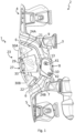
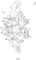
- the upper frame member 4 and the lower frame member 5 are pivotally connected therebetween and with the patella protection system 1 in order to rotate about respective rotation axes X1, X2, as shown in figures 1 , 1a and 2 , within a predetermined angular range relative to the patella protection system 1 when the leg is flexed.
- both the upper frame member 4 and the lower frame member 5 comprise a central edge portion 6 and a pair of side brackets 7 pivotally connected with the side brackets 7 of the other member by suitable hinge means 8, better illustrated in figures 1 , 1a , 2 , 7 , 9 , 10 , 12 and 13 .
- the hinge means 8 are of the four-pivot type in order for each of the upper member 4 and the lower member 5 to rotate about respective rotation axes X1, X2, as shown in figures 1 , 1a and 2 .
- the side brackets 7 and the central edge portion 6 of both the upper frame member 4 and the lower frame member 5 delimit a central space 9 for the housing of the patella protection system 1.
- the hinge means 8 are positioned at both the sides of the central space 9.
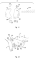
- each of the hinge means 8 comprises an outer plate 10 and an inner plate 11 defining an interspace 12 and coupled by at least two rivets 13 inserted in respective through holes 14.
- each of the plates 10, 11 comprises two through holes 14, as shown in figure 12 .
- the ends of the side brackets 7 are inserted in the interspace 12 and comprise through holes 15 (see figures 7 and 10 ) designed to be aligned with the holes 14 of the plates 10, 11 for the insertion of the rivets 13, as better shown in figure 13 .
- the rivets 13 define the rotation axes X1, X2 of the upper frame member 4 and lower frame member 5.
- the surface of the inner plate 11 oriented towards the space 9 may be covered with a layer of protection soft material, not shown in the figures, for protecting the knee on both its sides and avoiding injuries.
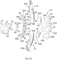
- the inner plates 11 of the hinge means 8 comprise flanges 16 (see figures 11 and 11a ) secured to patella protection system 1 on both its sides.
- each of the flanges 16 can comprise a respective slot 17 for the insertion of a connection pin 18 formed on the protection system 1, as better illustrated in figures 4 and 9 .
- the inner plate 11 is shown schematically without the flange 16.
- connection pin 18 may slide with a limited angular excursion within the slot 17, so as to assure a certain degree of freedom to the patella protection system 1 relative to the coupled upper frame member 4 and lower frame member 5.
- the hinge means 8 can comprise at least one stop member 20 designed to interact with the ends of the side brackets 7 for limiting the rotation of the upper frame member 4 and the lower frame member 5.
- the stop member 20 is positioned in the interspace 12 and may be secured to the inner surface of the inner plate 11 or the outer plate 10.
- the stop member 20 may be chosen among a set of stop members having different sizes and shapes (see figure 12 ).
- the user will select the stop member with the desired size in order to settle the angular range within which the upper frame member 4 and the lower frame member 5 can rotate.
- patella protection system 1 In the following a preferred embodiment of the patella protection system 1 will be described with reference to the components of the knee brace 2 described above.
- the patella protection system 1 comprises an upper member 21, designed to be positioned in proximity of the upper part of the wearer's leg, and a lower member 22, designed to be positioned in proximity of the lower part of the wearer's leg.
- the upper member 21 and the lower member 22 may have the same configuration, as shown in the figures.
- the patella protection system 1 further comprises an intermediate guard member 23 designed to be positioned over the patella and to be operatively connected to the upper member 21 and the lower member 22.
- the intermediate guard member 23 may have a different shape and configuration with respect to the upper member 21 and the lower member 22, as shown in the figures.
- the upper member 21 and the lower member 22 are secured, respectively, to the upper frame member 4 and the lower frame member 5 of the knee brace 2, preferably at their central edge portion 6, as shown in figures 2 and 7 .
- the upper member 21 and lower member 22 are designed to be connected to the upper and the lower parts of the leg by way of their connection with the upper frame member 4 and the lower frame member 5.
- the upper member 21 and the lower member 22 are not directly connected with the hinge means 8 described above, but they are designed to move jointly with the upper frame member 4 and the lower frame member 5 of the knee brace 2.
- the intermediate guard member 23 is connected to the hinge means 8, namely it comprises, at both its sides, the respective connection pin 18, as described above, inserted in the slot 17 of a respective flange 16, as better shown in figure 9 .
- the upper member 21 and the lower member 22 are designed to move, jointly with the upper frame member 4 and the lower frame member 5, within the intermediate guard member 23.
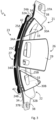
- the upper member 21 and the lower member 22 move between a straight configuration, better illustrated in figures 1 , 1a and 3 , and an angulated configuration, better illustrated in figures 2 , 4 and 5 .
- the upper member 21 and the lower member 22 have at least a reduced degree of overlap there between within the intermediate guard member 23, as shown in figure 5 .
- the intermediate guard member 23 is a box-like member with end openings 24A, 24B and an inner cavity 25 for the slidable insertion and guidance of the upper member 21 and the lower member 22 during the movement thereof between the straight and the angulated configuration, and viceversa.
- the upper member 21 and the lower member 22 are inserted in the inner cavity 25 and are positioned over the patella.
- the upper member 21 and the lower member 22 occupy the space between the edge portions 6 of the upper frame member 4 and the lower frame member 5 and the intermediate guard member 23.
- the intermediate guard member 23 of the patella protection system 1 can be formed by a pair of shells 26, 27 coupled there between and designed to delimit the inner cavity 25.
- the intermediate guard member 23 comprises an inner shell 26, which faces the knee of the user when the patella protection system 1 is in use, and an outer shell 27 oriented to the opposite side, as shown in figures 3-5 .
- the inner cavity 25 is delimited between the inner surfaces 39 of the inner shell 26 and the outer shell 27, which have a concave shape.
- the upper member 21 and the lower member 22 have a predetermined degree of overlap within the intermediate guard member 23, it is meant that the upper member 21 and the lower member 22 overlap the inner shell 26, namely its inner surface 39, when they are inserted in the inner cavity 25.
- the shells 26, 27, as illustrated in the figures 8 and 9 may be connected by snap-fit connection means 28 or by different types of connection, for example by means of screws, without prejudice to the scope of protection of the present invention. Further, the two shells 26, 27 could also be integrally formed with the inner cavity 25 provided there between.
- the outer shell 27 remains always exposed outward, both in the straight configuration and in the angulated configuration, since the upper member 21 and the lower member 22 slide inside the inner cavity 25 of the intermediate guard member 23.
- Such a configuration allows for an increased absorption of the impacts by deformation of the walls of the shells 26, 27, according with the standard EN 1621-1.
- the inner shell 26 and the outer shell 27 comprise at least two portions 29, 30A, 30B connected by at least one hinge section 31A, 31B.
- the inner shell 26 and the outer shell 27 comprise three portions, namely a central portion 29, an upper portion 30A and a lower portion 30B.
- the upper portion 30A is the portion proximate to the upper member 21, and the lower portion 30B is the portion proximate to the lower member 22.
- the number of portions of the inner shell 26 and the outer shell 27 can also be different, according with the use of the patella protection system 1, without prejudice to the scope of protection of the present invention.
- the upper portion 30A and the lower portion 30B are connected to the central portion 29 at a respective hinge section 31A, 31B and all the portions 29, 30A, 30B define transverse extension axes T with reference to an elongated axis Y which corresponds to the extension axis of the leg, as shown in figure 6 .
- each of the shells 26, 27 can be manufactured by injection as a single segmented element so as to define the three portions 29, 30A, 30B connected by the hinge sections 31A, 31B.
- the at least one hinge section 31A, 31B has a reduced thickness relative to the shells portions 29, 30A, 30B.
- the material of the hinge sections 31A, 31B is the same of the material of the portions 29, 30A, 30B but it has a reduced thickness relative to the material of the portions 29, 30A, 30B.
- the inner cavity 25 of the intermediate guard member 23 may be segmented as well as the portions 29, 30A, 30B so as to form three parts 25A, 25B, 25C, as shown in figures 3 and 5 .
- the parts 25A, 25B, 25C are defined respectively inside the portions 29, 30A, 30B.
- the above indicated end openings 24A, 24B can be formed on the transverse ends 32A, 32B of the upper portion 30A and the lower portion 30B which are not connected to the central portion 29, as illustrated in figures 3 and 5 .
- the central portion 29 of the inner shell 26 can comprise, at both its transverse sides, the connection pin 18 which is designed to be inserted in the slot 17 of the flange 16 of the hinge means 8, as illustrated in figure 9 .
- each portion 29, 30A, 30B of the inner shell 26 and the outer shell 27 comprises at least one ventilation hole 33 aligned with the hole of the other shell for allowing the breathability of the knee when the patella protection system 1 is in use.
- a plurality of ventilation holes 33 distributed in series 33A along the portions 29, 30A, 30B of the inner shell 26 and the outer shell 27.
- the ventilation holes 33 of the inner shell 26 are aligned with the ventilation holes 33 of the outer shell 27.
- the ventilation holes 33 of the inner shell 26 can have shaped walls 43 which project inside the cavity 25 when the intermediate guard member 23 is assembled and which engage the ventilation holes 33 of the outer shell 27, as shown in figures 8, 9 , 11 and 11a .
- each of the upper member 21 and lower member 22 comprises at least one finger-like projection 34 and the inner cavity 25 of the intermediate member 23 comprises at least one passage 35 for the slidable insertion and guidance of said at least one finger-like projection 34.
- the upper member 21 and the lower member 22 can comprise a plurality of finger-like projections 34, preferably transversely staggered, while the inner cavity 25 can comprise a plurality of passages 35, also preferably transversely staggered for the insertion of a respective projection 34.
- the finger-like projections 34 define longitudinal spaces 36 therebetween.
- the upper member 21 and the lower member 22 comprise a respective connection portion 37A, 37B from which the projections 34 extent and designed to be connected to the central edge portion 6 of the respective upper frame member 4 or lower frame member 5 by suitable connection means 38, as shown in figures 3 and 5 .
- the finger-like projections 34 preferably have a longitudinal extension equal to the three-piece intermediate guard member 23 and may be made of a semi-rigid flexible material in order to be deformable during their sliding in the passages 35.
- the finger-like projections 34 are superimposed in the passages 35 when the upper member 21 and the lower member 22 are in the straight configuration, as shown in figure 3 , and the ventilation holes 33 are not obstructed, because of the presence of the spaces 36 between the finger-like projections 34.
- the shells 26, 27 and the free ends 34A of the finger-like projections 34 form a stack inside the inner cavity 25, as shown in figure 3 , with the free ends 34A superimposed and positioned between the inner shell 26 and the outer shell 27.
- the finger-like projections 34 longitudinally cross the spaces between the central portion 29 and the upper portion 30A and the lower portion 30B wherein the hinge sections 31A, 31B are not present.
- stabilizer wings 44A, 44B can be positioned between the inner shell 26 and the outer shell 27 at the outer sides of the hinge sections 31A, 31B so as to close the gap between the central portion 29 and the upper and lower portions 30A, 30B.
- the stabilizer wings 44A, 44B are preferably provided with a seat 45 designed to engage the shaped walls 43 projecting from the inner shell 26.
- the stabilizer wings 44A, 44B have the function to prevent that the finger-like projections 34 during their movements can slide out from the inner cavity 25.
- the free ends 34A of the finger-like projections 34 are in contact with the inner surface 39, i.e. the surface facing the inner cavity 25, of the outer shell 27 and are flexed, as better shown in figure 5 .
- At least one of the finger-like projections 34 comprises a respective elongated slot 40 with two opposed ends 41.
- the slot 40 may have an extension smaller than the extension of the respective projection 34.
- At least one of the passages 35 can comprise at least one engaging pin 42, preferably a pair of engaging pins 42, shown in figures 3 and 7-10 , which are slidably inserted in the slot 40.
- the pins 42 may be formed in the inner surfaces 39 of the upper and lower portions 30 of both the inner 26 and outer shells 27.
- the opposed ends 41 of the slot 40 define limit positions for the sliding of the pins 42 which correspond to the straight configuration or to the angulated configuration of the upper member 21 and lower member 22.
- the patella protection system 1 when the pins 42 of the intermediate guard member 23 abut against the end 41 of the slot 40 proximate to the connection portion 37A, 37B of the upper member 21 or the lower member 22, the patella protection system 1 is in the straight configuration. Instead, when the pins 42 abut against the end 41 of the slot 40 proximate to the free ends 34A of the finger-like projections 34, the patella protection system 1 is in the angulated configuration.
- a plurality of finger-like projections 34 when a plurality of finger-like projections 34 is provided, there could be provided also a plurality of slots 40 each formed on a respective finger-like projection 34. In the figures, only the central projections 34 are provided with respective slots 40. Accordingly, for each of the slots 40 a pair of pins 42 is provided and is formed in transverse staggered positions in the inner shell 26 and in the outer shell 27.
- the patella protection system comprises a box-like intermediate guard member which allows the insertion and guidance of the upper member and lower member.
- the intermediate guard member is formed by at least three pieces which could be deformed to adapt the shape of the patella protection system to the knee when it is flexed.
- the outer shell of the intermediate guard member remains always exposed during the operations of the patella protection system, thus allowing for an improved absorption of the impacts against the brace.
- the intermediate guard member further comprises a plurality of openings which allows the breathability of the knee when the patella protection system and the brace are in use.
- the patella protection system could also be coupled with a wearable article different from a knee brace, provided that its functioning remains the same described in the present application.
- the protection system could be designed for protecting the wearer's elbow, or other joints which move from a straight configuration to an angulated configuration.
- the person skilled in the art may, in order to satisfy specific requirements, make modifications to and/or replace elements described with equivalent elements, without thereby departing from the scope of the accompanying claims.
- the skilled person could replace the material of the components of the brace, or select a different type of connection between the shells, or further change the shape and the number of projections without thereby departing from the scope of the accompanying claims.
Landscapes
- Health & Medical Sciences (AREA)
- General Health & Medical Sciences (AREA)
- Engineering & Computer Science (AREA)
- Textile Engineering (AREA)
- Physical Education & Sports Medicine (AREA)
- Biomedical Technology (AREA)
- Vascular Medicine (AREA)
- Life Sciences & Earth Sciences (AREA)
- Animal Behavior & Ethology (AREA)
- Heart & Thoracic Surgery (AREA)
- Public Health (AREA)
- Veterinary Medicine (AREA)
- Orthopedic Medicine & Surgery (AREA)
- Nursing (AREA)
- Orthopedics, Nursing, And Contraception (AREA)
- Medicines Containing Antibodies Or Antigens For Use As Internal Diagnostic Agents (AREA)
Claims (17)
- Patellaschutzsystem (1), das zur Verwendung durch einen Träger geeignet ist, umfassend:- ein oberes Element (21), das dazu ausgebildet ist, in der Nähe eines oberen Teils des Beins des Trägers positioniert zu sein;- ein unteres Element (22), das dazu ausgebildet ist, in der Nähe eines unteren Teils des Beins des Trägers positioniert zu sein;- ein Zwischenschutzelement (23), das dazu ausgebildet ist, über der Patella positioniert und mit dem oberen Element (21) und dem unteren Element (22) wirkungsmäßig verbunden zu sein;wobei das obere Element (21) und das untere Element (22) dazu ausgebildet sind, sich innerhalb des Zwischenschutzelements (23) zwischen einer geraden Anordnung und einer gewinkelten Anordnung zu bewegen, wobei das Patellaschutzsystem dadurch gekennzeichnet ist, dassdas obere Element (21) und das untere Element (22) einen vorbestimmten Grad an Überlappung dazwischen innerhalb des Zwischenschutzelements (23) in der geraden Anordnung und einen verringerten Grad an Überlappung dazwischen innerhalb des Zwischenschutzelements (23) in der angewinkelten Anordnung aufweisen.
- Patellaschutzsystem (1) nach Anspruch 1, wobei das Zwischenschutzelement (23) ein kastenartiges Element ist, das einen inneren Hohlraum (25) und Endöffnungen (24A, 24B) zum verschiebbaren Einführen und Führen des oberen Elements (21) und des unteren Elements (22) aufweist.
- Patellaschutzsystem (1) nach Anspruch 2, wobei das Zwischenschutzelement (23) durch ein Paar von Hüllen (26, 27) gebildet ist, die dazwischen gekoppelt und dazu ausgebildet sind, den inneren Hohlraum (25) zu begrenzen.
- Patellaschutzsystem (1) nach Anspruch 3, wobei jede Hülle (26, 27) des Zwischenschutzelements (23) mindestens zwei Abschnitte (29, 30A, 30B) umfasst, die durch mindestens einen Gelenkabschnitt (31 A, 31B) miteinander verbunden sind.
- Patellaschutzsystem (1) nach Anspruch 4, wobei der mindestens eine Gelenkabschnitt (31 A, 31B) eine verringerte Dicke relativ zu den Hüllenabschnitten (29, 30A, 30B) aufweist.
- Patellaschutzsystem (1) nach Anspruch 5, wobei jede Hülle (26, 27) einen zentralen Abschnitt (29), einen oberen Abschnitt (30A) und einen unteren Abschnitt (30B) umfasst, wobei der obere Abschnitt (30A) und der untere Abschnitt (30B) mit dem zentralen Abschnitt (29) an einem jeweiligen Gelenkabschnitt (31A, 31B) verbunden sind.
- Patellaschutzsystem (1) nach Anspruch 6, wobei jeder der Abschnitte (29, 30A, 30B) mindestens ein Lüftungsloch (33) umfasst.
- Patellaschutzsystem (1) nach Anspruch 1, wobei das obere Element (21) und das untere Element (22) mindestens einen fingerartigen Vorsprung (34) umfassen, und wobei das Zwischenschutzelement (23) einen inneren Hohlraum (25) umfasst, der mindestens einen Durchgang (35) zum verschiebbaren Einführen und Führen des mindestens einen fingerartigen Vorsprungs (34) umfasst.
- Patellaschutzsystem (1) nach Anspruch 8, wobei das obere Element (21) und das untere Element (22) eine Mehrzahl von fingerartigen Vorsprüngen (34) umfassen, und wobei der innere Hohlraum (25) eine Mehrzahl von Durchgängen (35) umfasst, wobei jeder Durchgang (35) zum verschiebbaren Einführen und Führen eines jeweiligen fingerartigen Vorsprungs (34) ausgebildet ist.
- Patellaschutzsystem (1) nach Anspruch 9, wobei die fingerartigen Vorsprünge (34) des oberen Elements (21) und des unteren Elements (22) innerhalb jedes der Durchgänge (35) überlagert sind, wenn sich das Patellaschutzsystem (1) in der geraden Anordnung befindet.
- Patellaschutzsystem (1) nach Anspruch 9, wobei die fingerartigen Vorsprünge (34) aus einem halbstarren flexiblen Material hergestellt sind.
- Patellaschutzsystem (1) nach Anspruch 9, wobei mindestens einer der fingerartigen Vorsprünge (34) einen länglichen Schlitz (40) mit zwei gegenüberliegenden Enden (41) umfasst.
- Patellaschutzsystem (1) nach Anspruch 12, wobei mindestens einer der Durchgänge (35) einen jeweiligen Eingriffsstift (42) umfasst, der verschiebbar in den mindestens einen Schlitz (40) eingeführt ist.
- Patellaschutzsystem nach Anspruch 13, dadurch gekennzeichnet, dass die gegenüberliegenden Enden (41) jedes Schlitzes (40) Begrenzungspositionen für das Verschieben des Stifts (42) definieren; wobei die Begrenzungspositionen der geraden Anordnung oder der gewinkelten Anordnung des oberen Elements (21) und des unteren Elements (22) entsprechen.
- Kniestütze (2), umfassend:ein oberes Rahmenelement (4), das dazu ausgebildet ist, am oberen Teil des Beins des Trägers befestigt zu sein und diesen zu schützen;ein unteres Rahmenelement (5), das dazu ausgebildet ist, am unteren Teil des Beins des Trägers befestigt zu sein und diesen zu schützen;ein Patellaschutzsystem (1), das zwischen dem oberen Rahmenelement (4) und dem unteren Rahmenelement (5) angeordnet ist;wobei das obere Rahmenelement (4) und das untere Rahmenelement (5) dazwischen und mit dem Patellaschutzsystem (1) schwenkbar verbunden sind, undwobei das Patellaschutzsystem (1) ein oberes Element (21), das an dem oberen Rahmenelement (4) befestigt ist, ein unteres Element (22), das an dem unteren Rahmenelement (5) befestigt ist, und ein Zwischenschutzelement (23) umfasst, das dazu ausgebildet ist, über der Patella positioniert und mit dem oberen Element (21) und dem unteren Element (22) wirkungsmäßig verbunden zu sein;wobei das obere Element (21) und das untere Element (22) dazu ausgebildet sind, sich innerhalb des Zwischenschutzelements (23) zwischen einer geraden Anordnung und einer gewinkelten Anordnung zu bewegen, wobei die Kniestütze dadurch gekennzeichnet ist, dassdas obere Element (21) und das untere Element (22) einen vorbestimmten Grad an Überlappung dazwischen innerhalb des Zwischenschutzelements (23) in der geraden Anordnung und einen verringerten Grad an Überlappung dazwischen innerhalb des Zwischenschutzelements (23) in der angewinkelten Anordnung aufweisen.
- Kniestütze (2) nach Anspruch 15, wobei das Zwischenschutzelement (23) ein kastenartiges Element ist, das einen inneren Hohlraum (25) und Endöffnungen (24A, 2413) zum verschiebbaren Einführen und Führen des oberen Elements (21) und des unteren Elements (22) aufweist.
- Kniestütze (2) nach Anspruch 15, wobei das obere Rahmenelement (4) und das untere Rahmenelement (5) jeweils ein Paar von Seitenhalterungen (7) umfassen, die dazwischen und um eine jeweilige Drehachse (X1, X2) durch Gelenkmittel (8) schwenkbar verbunden sind, die mindestens ein Anschlagelement (20) zum Begrenzen der Drehung des oberen Rahmenelements (4) und des unteren Rahmenelements (5) umfassen.
Applications Claiming Priority (2)
| Application Number | Priority Date | Filing Date | Title |
|---|---|---|---|
| IT102018000008174A IT201800008174A1 (it) | 2018-08-23 | 2018-08-23 | Sistema di protezione della rotula e ginocchiera comprendente tale sistema di protezione della rotula |
| PCT/EP2019/072347 WO2020038987A1 (en) | 2018-08-23 | 2019-08-21 | Patella protection system and knee brace comprising such a patella protection system |
Publications (2)
| Publication Number | Publication Date |
|---|---|
| EP3840601A1 EP3840601A1 (de) | 2021-06-30 |
| EP3840601B1 true EP3840601B1 (de) | 2023-09-27 |
Family
ID=63896598
Family Applications (1)
| Application Number | Title | Priority Date | Filing Date |
|---|---|---|---|
| EP19755389.4A Active EP3840601B1 (de) | 2018-08-23 | 2019-08-21 | Patellaschutzsystem und knieorthese mit solch einem patellaschutzsystem |
Country Status (4)
| Country | Link |
|---|---|
| US (1) | US12016405B2 (de) |
| EP (1) | EP3840601B1 (de) |
| IT (1) | IT201800008174A1 (de) |
| WO (1) | WO2020038987A1 (de) |
Families Citing this family (4)
| Publication number | Priority date | Publication date | Assignee | Title |
|---|---|---|---|---|
| CN113171267B (zh) * | 2021-04-21 | 2022-08-05 | 吉林大学第一医院 | 一种防止屈伸拉伤的膝关节韧带断裂康复训练装置 |
| IT202100021542A1 (it) | 2021-08-09 | 2023-02-09 | Alpinestars Res Spa | Ginocchiera |
| CN114522412A (zh) * | 2022-03-17 | 2022-05-24 | 湖南师范大学 | 一种力量训练用膝盖防内扣保护器 |
| US20250228689A1 (en) * | 2022-03-31 | 2025-07-17 | Ossur Iceland Ehf | Impact guard for knee brace |
Family Cites Families (14)
| Publication number | Priority date | Publication date | Assignee | Title |
|---|---|---|---|---|
| US2587166A (en) * | 1950-01-06 | 1952-02-26 | Vance Jovick | Knee-supporting brace |
| US4068312A (en) * | 1976-11-10 | 1978-01-17 | Thomas Ledesma | Athletic knee guard |
| SE426359B (sv) * | 1981-05-19 | 1983-01-17 | Lars Eghamn | Ledanordning for benskydd |
| US4599748A (en) * | 1985-03-22 | 1986-07-15 | Francis R. Shearer | Protective knee guard |
| DE3626005A1 (de) | 1986-07-31 | 1988-02-04 | Aerodynamische Autoteile Aav | Stossschutz fuer knie- oder ellbogengelenk |
| GB9303147D0 (en) | 1993-02-17 | 1993-03-31 | Doyle Kelvin C | Limb protector |
| US6796951B2 (en) * | 2001-02-02 | 2004-09-28 | Asterisk.Asterisk. Llc | Anatomical joint brace with adjustable joint extension limiter |
| CA2337566C (en) * | 2001-02-20 | 2007-03-27 | Chris Budda | Body guard |
| SE0100999L (sv) * | 2001-03-22 | 2002-05-07 | Sportopedgruppen Ab | Ledanordning för benskydd |
| ITTV20030133A1 (it) * | 2003-09-26 | 2005-03-27 | Alpinestars Res Srl | Struttura di protezione degli arti inferiori del corpo umano. |
| WO2008100486A2 (en) * | 2007-02-12 | 2008-08-21 | Ossur Hf | Orthopedic brace and component for use therewith |
| US20110098618A1 (en) * | 2007-05-03 | 2011-04-28 | Darren Fleming | Cable Knee Brace System |
| US9693887B2 (en) | 2013-12-20 | 2017-07-04 | Asterick, LLC | Multi-piece joint guard |
| US10420668B2 (en) * | 2014-11-20 | 2019-09-24 | Ossur Iceland Ehf | Patella cup |
-
2018
- 2018-08-23 IT IT102018000008174A patent/IT201800008174A1/it unknown
-
2019
- 2019-08-21 EP EP19755389.4A patent/EP3840601B1/de active Active
- 2019-08-21 WO PCT/EP2019/072347 patent/WO2020038987A1/en not_active Ceased
- 2019-08-21 US US17/270,310 patent/US12016405B2/en active Active
Also Published As
| Publication number | Publication date |
|---|---|
| WO2020038987A1 (en) | 2020-02-27 |
| US12016405B2 (en) | 2024-06-25 |
| IT201800008174A1 (it) | 2020-02-23 |
| US20210195969A1 (en) | 2021-07-01 |
| EP3840601A1 (de) | 2021-06-30 |
Similar Documents
| Publication | Publication Date | Title |
|---|---|---|
| EP3840601B1 (de) | Patellaschutzsystem und knieorthese mit solch einem patellaschutzsystem | |
| US7958568B2 (en) | Glove with support system | |
| AU2002345220B2 (en) | Protective headgear | |
| EP2613744B1 (de) | Scharnier für orthopädische vorrichtungen | |
| US9693887B2 (en) | Multi-piece joint guard | |
| CN102026595B (zh) | 腿支承件 | |
| US20130312152A1 (en) | Two-way protective pad construction | |
| US20130269075A1 (en) | Conformable device for protecting a joint area of the human body | |
| AU2002345220A1 (en) | Protective headgear | |
| US11731028B2 (en) | Leg pad | |
| US7752679B2 (en) | Protective gear | |
| US8813262B2 (en) | Wrist protector for a sport glove | |
| WO2008037584A1 (en) | Lumbar back brace support member for a back brace support belt | |
| US5561857A (en) | Shin pad with lateral support | |
| FI71657B (fi) | Skyddshjaelm | |
| US20070214538A1 (en) | Hockey shin guard | |
| EP4384125B1 (de) | Polyzentrisches scharnier für eine knieorthese und knieorthese mit solch einem polyzentrischen scharnier | |
| US20240365892A1 (en) | Knee brace | |
| US20160262465A1 (en) | Joint protector system | |
| KR100749958B1 (ko) | 관절 보호대용 완충부재 및 이를 갖는 관절 보호대 | |
| CA2263028A1 (en) | Protective guard | |
| EP3834644B1 (de) | Verbesserter schienbeinschutz und entsprechendes herstellungsverfahren | |
| EP1563811B1 (de) | Orthese zum Schutze des Handgelenkes, vor allem zur Sportausübung. | |
| CA2539524A1 (en) | Hockey shin guard | |
| GB2304270A (en) | Protective pad for absorbing impact |
Legal Events
| Date | Code | Title | Description |
|---|---|---|---|
| STAA | Information on the status of an ep patent application or granted ep patent |
Free format text: STATUS: UNKNOWN |
|
| STAA | Information on the status of an ep patent application or granted ep patent |
Free format text: STATUS: THE INTERNATIONAL PUBLICATION HAS BEEN MADE |
|
| PUAI | Public reference made under article 153(3) epc to a published international application that has entered the european phase |
Free format text: ORIGINAL CODE: 0009012 |
|
| STAA | Information on the status of an ep patent application or granted ep patent |
Free format text: STATUS: REQUEST FOR EXAMINATION WAS MADE |
|
| 17P | Request for examination filed |
Effective date: 20210309 |
|
| AK | Designated contracting states |
Kind code of ref document: A1 Designated state(s): AL AT BE BG CH CY CZ DE DK EE ES FI FR GB GR HR HU IE IS IT LI LT LU LV MC MK MT NL NO PL PT RO RS SE SI SK SM TR |
|
| DAV | Request for validation of the european patent (deleted) | ||
| DAX | Request for extension of the european patent (deleted) | ||
| GRAP | Despatch of communication of intention to grant a patent |
Free format text: ORIGINAL CODE: EPIDOSNIGR1 |
|
| STAA | Information on the status of an ep patent application or granted ep patent |
Free format text: STATUS: GRANT OF PATENT IS INTENDED |
|
| INTG | Intention to grant announced |
Effective date: 20230317 |
|
| GRAS | Grant fee paid |
Free format text: ORIGINAL CODE: EPIDOSNIGR3 |
|
| GRAA | (expected) grant |
Free format text: ORIGINAL CODE: 0009210 |
|
| STAA | Information on the status of an ep patent application or granted ep patent |
Free format text: STATUS: THE PATENT HAS BEEN GRANTED |
|
| AK | Designated contracting states |
Kind code of ref document: B1 Designated state(s): AL AT BE BG CH CY CZ DE DK EE ES FI FR GB GR HR HU IE IS IT LI LT LU LV MC MK MT NL NO PL PT RO RS SE SI SK SM TR |
|
| REG | Reference to a national code |
Ref country code: GB Ref legal event code: FG4D |
|
| REG | Reference to a national code |
Ref country code: CH Ref legal event code: EP |
|
| REG | Reference to a national code |
Ref country code: DE Ref legal event code: R096 Ref document number: 602019038237 Country of ref document: DE |
|
| REG | Reference to a national code |
Ref country code: IE Ref legal event code: FG4D |
|
| REG | Reference to a national code |
Ref country code: NL Ref legal event code: FP Ref country code: LT Ref legal event code: MG9D |
|
| PG25 | Lapsed in a contracting state [announced via postgrant information from national office to epo] |
Ref country code: GR Free format text: LAPSE BECAUSE OF FAILURE TO SUBMIT A TRANSLATION OF THE DESCRIPTION OR TO PAY THE FEE WITHIN THE PRESCRIBED TIME-LIMIT Effective date: 20231228 |
|
| PG25 | Lapsed in a contracting state [announced via postgrant information from national office to epo] |
Ref country code: SE Free format text: LAPSE BECAUSE OF FAILURE TO SUBMIT A TRANSLATION OF THE DESCRIPTION OR TO PAY THE FEE WITHIN THE PRESCRIBED TIME-LIMIT Effective date: 20230927 Ref country code: RS Free format text: LAPSE BECAUSE OF FAILURE TO SUBMIT A TRANSLATION OF THE DESCRIPTION OR TO PAY THE FEE WITHIN THE PRESCRIBED TIME-LIMIT Effective date: 20230927 Ref country code: NO Free format text: LAPSE BECAUSE OF FAILURE TO SUBMIT A TRANSLATION OF THE DESCRIPTION OR TO PAY THE FEE WITHIN THE PRESCRIBED TIME-LIMIT Effective date: 20231227 Ref country code: LV Free format text: LAPSE BECAUSE OF FAILURE TO SUBMIT A TRANSLATION OF THE DESCRIPTION OR TO PAY THE FEE WITHIN THE PRESCRIBED TIME-LIMIT Effective date: 20230927 Ref country code: LT Free format text: LAPSE BECAUSE OF FAILURE TO SUBMIT A TRANSLATION OF THE DESCRIPTION OR TO PAY THE FEE WITHIN THE PRESCRIBED TIME-LIMIT Effective date: 20230927 Ref country code: HR Free format text: LAPSE BECAUSE OF FAILURE TO SUBMIT A TRANSLATION OF THE DESCRIPTION OR TO PAY THE FEE WITHIN THE PRESCRIBED TIME-LIMIT Effective date: 20230927 Ref country code: GR Free format text: LAPSE BECAUSE OF FAILURE TO SUBMIT A TRANSLATION OF THE DESCRIPTION OR TO PAY THE FEE WITHIN THE PRESCRIBED TIME-LIMIT Effective date: 20231228 Ref country code: FI Free format text: LAPSE BECAUSE OF FAILURE TO SUBMIT A TRANSLATION OF THE DESCRIPTION OR TO PAY THE FEE WITHIN THE PRESCRIBED TIME-LIMIT Effective date: 20230927 |
|
| REG | Reference to a national code |
Ref country code: AT Ref legal event code: MK05 Ref document number: 1614509 Country of ref document: AT Kind code of ref document: T Effective date: 20230927 |
|
| PG25 | Lapsed in a contracting state [announced via postgrant information from national office to epo] |
Ref country code: IS Free format text: LAPSE BECAUSE OF FAILURE TO SUBMIT A TRANSLATION OF THE DESCRIPTION OR TO PAY THE FEE WITHIN THE PRESCRIBED TIME-LIMIT Effective date: 20240127 |
|
| PG25 | Lapsed in a contracting state [announced via postgrant information from national office to epo] |
Ref country code: AT Free format text: LAPSE BECAUSE OF FAILURE TO SUBMIT A TRANSLATION OF THE DESCRIPTION OR TO PAY THE FEE WITHIN THE PRESCRIBED TIME-LIMIT Effective date: 20230927 |
|
| P01 | Opt-out of the competence of the unified patent court (upc) registered |
Effective date: 20240319 |
|
| PG25 | Lapsed in a contracting state [announced via postgrant information from national office to epo] |
Ref country code: ES Free format text: LAPSE BECAUSE OF FAILURE TO SUBMIT A TRANSLATION OF THE DESCRIPTION OR TO PAY THE FEE WITHIN THE PRESCRIBED TIME-LIMIT Effective date: 20230927 |
|
| PG25 | Lapsed in a contracting state [announced via postgrant information from national office to epo] |
Ref country code: SM Free format text: LAPSE BECAUSE OF FAILURE TO SUBMIT A TRANSLATION OF THE DESCRIPTION OR TO PAY THE FEE WITHIN THE PRESCRIBED TIME-LIMIT Effective date: 20230927 Ref country code: RO Free format text: LAPSE BECAUSE OF FAILURE TO SUBMIT A TRANSLATION OF THE DESCRIPTION OR TO PAY THE FEE WITHIN THE PRESCRIBED TIME-LIMIT Effective date: 20230927 Ref country code: IS Free format text: LAPSE BECAUSE OF FAILURE TO SUBMIT A TRANSLATION OF THE DESCRIPTION OR TO PAY THE FEE WITHIN THE PRESCRIBED TIME-LIMIT Effective date: 20240127 Ref country code: ES Free format text: LAPSE BECAUSE OF FAILURE TO SUBMIT A TRANSLATION OF THE DESCRIPTION OR TO PAY THE FEE WITHIN THE PRESCRIBED TIME-LIMIT Effective date: 20230927 Ref country code: EE Free format text: LAPSE BECAUSE OF FAILURE TO SUBMIT A TRANSLATION OF THE DESCRIPTION OR TO PAY THE FEE WITHIN THE PRESCRIBED TIME-LIMIT Effective date: 20230927 Ref country code: CZ Free format text: LAPSE BECAUSE OF FAILURE TO SUBMIT A TRANSLATION OF THE DESCRIPTION OR TO PAY THE FEE WITHIN THE PRESCRIBED TIME-LIMIT Effective date: 20230927 Ref country code: AT Free format text: LAPSE BECAUSE OF FAILURE TO SUBMIT A TRANSLATION OF THE DESCRIPTION OR TO PAY THE FEE WITHIN THE PRESCRIBED TIME-LIMIT Effective date: 20230927 Ref country code: PT Free format text: LAPSE BECAUSE OF FAILURE TO SUBMIT A TRANSLATION OF THE DESCRIPTION OR TO PAY THE FEE WITHIN THE PRESCRIBED TIME-LIMIT Effective date: 20240129 Ref country code: SK Free format text: LAPSE BECAUSE OF FAILURE TO SUBMIT A TRANSLATION OF THE DESCRIPTION OR TO PAY THE FEE WITHIN THE PRESCRIBED TIME-LIMIT Effective date: 20230927 |
|
| PG25 | Lapsed in a contracting state [announced via postgrant information from national office to epo] |
Ref country code: PL Free format text: LAPSE BECAUSE OF FAILURE TO SUBMIT A TRANSLATION OF THE DESCRIPTION OR TO PAY THE FEE WITHIN THE PRESCRIBED TIME-LIMIT Effective date: 20230927 |
|
| REG | Reference to a national code |
Ref country code: DE Ref legal event code: R097 Ref document number: 602019038237 Country of ref document: DE |
|
| PG25 | Lapsed in a contracting state [announced via postgrant information from national office to epo] |
Ref country code: DK Free format text: LAPSE BECAUSE OF FAILURE TO SUBMIT A TRANSLATION OF THE DESCRIPTION OR TO PAY THE FEE WITHIN THE PRESCRIBED TIME-LIMIT Effective date: 20230927 |
|
| PG25 | Lapsed in a contracting state [announced via postgrant information from national office to epo] |
Ref country code: DK Free format text: LAPSE BECAUSE OF FAILURE TO SUBMIT A TRANSLATION OF THE DESCRIPTION OR TO PAY THE FEE WITHIN THE PRESCRIBED TIME-LIMIT Effective date: 20230927 |
|
| PLBE | No opposition filed within time limit |
Free format text: ORIGINAL CODE: 0009261 |
|
| STAA | Information on the status of an ep patent application or granted ep patent |
Free format text: STATUS: NO OPPOSITION FILED WITHIN TIME LIMIT |
|
| 26N | No opposition filed |
Effective date: 20240628 |
|
| PG25 | Lapsed in a contracting state [announced via postgrant information from national office to epo] |
Ref country code: SI Free format text: LAPSE BECAUSE OF FAILURE TO SUBMIT A TRANSLATION OF THE DESCRIPTION OR TO PAY THE FEE WITHIN THE PRESCRIBED TIME-LIMIT Effective date: 20230927 |
|
| PG25 | Lapsed in a contracting state [announced via postgrant information from national office to epo] |
Ref country code: SI Free format text: LAPSE BECAUSE OF FAILURE TO SUBMIT A TRANSLATION OF THE DESCRIPTION OR TO PAY THE FEE WITHIN THE PRESCRIBED TIME-LIMIT Effective date: 20230927 |
|
| PG25 | Lapsed in a contracting state [announced via postgrant information from national office to epo] |
Ref country code: BG Free format text: LAPSE BECAUSE OF FAILURE TO SUBMIT A TRANSLATION OF THE DESCRIPTION OR TO PAY THE FEE WITHIN THE PRESCRIBED TIME-LIMIT Effective date: 20230927 |
|
| PG25 | Lapsed in a contracting state [announced via postgrant information from national office to epo] |
Ref country code: BG Free format text: LAPSE BECAUSE OF FAILURE TO SUBMIT A TRANSLATION OF THE DESCRIPTION OR TO PAY THE FEE WITHIN THE PRESCRIBED TIME-LIMIT Effective date: 20230927 |
|
| REG | Reference to a national code |
Ref country code: CH Ref legal event code: PL |
|
| PG25 | Lapsed in a contracting state [announced via postgrant information from national office to epo] |
Ref country code: LU Free format text: LAPSE BECAUSE OF NON-PAYMENT OF DUE FEES Effective date: 20240821 |
|
| PG25 | Lapsed in a contracting state [announced via postgrant information from national office to epo] |
Ref country code: MC Free format text: LAPSE BECAUSE OF FAILURE TO SUBMIT A TRANSLATION OF THE DESCRIPTION OR TO PAY THE FEE WITHIN THE PRESCRIBED TIME-LIMIT Effective date: 20230927 Ref country code: CH Free format text: LAPSE BECAUSE OF NON-PAYMENT OF DUE FEES Effective date: 20240831 |
|
| REG | Reference to a national code |
Ref country code: BE Ref legal event code: MM Effective date: 20240831 |
|
| PG25 | Lapsed in a contracting state [announced via postgrant information from national office to epo] |
Ref country code: BE Free format text: LAPSE BECAUSE OF NON-PAYMENT OF DUE FEES Effective date: 20240831 |
|
| PG25 | Lapsed in a contracting state [announced via postgrant information from national office to epo] |
Ref country code: IE Free format text: LAPSE BECAUSE OF NON-PAYMENT OF DUE FEES Effective date: 20240821 |
|
| PGFP | Annual fee paid to national office [announced via postgrant information from national office to epo] |
Ref country code: NL Payment date: 20250826 Year of fee payment: 7 |
|
| PGFP | Annual fee paid to national office [announced via postgrant information from national office to epo] |
Ref country code: DE Payment date: 20250827 Year of fee payment: 7 |
|
| PGFP | Annual fee paid to national office [announced via postgrant information from national office to epo] |
Ref country code: IT Payment date: 20250722 Year of fee payment: 7 |
|
| PGFP | Annual fee paid to national office [announced via postgrant information from national office to epo] |
Ref country code: GB Payment date: 20250827 Year of fee payment: 7 |
|
| PGFP | Annual fee paid to national office [announced via postgrant information from national office to epo] |
Ref country code: FR Payment date: 20250825 Year of fee payment: 7 |
|
| PG25 | Lapsed in a contracting state [announced via postgrant information from national office to epo] |
Ref country code: CY Free format text: LAPSE BECAUSE OF FAILURE TO SUBMIT A TRANSLATION OF THE DESCRIPTION OR TO PAY THE FEE WITHIN THE PRESCRIBED TIME-LIMIT; INVALID AB INITIO Effective date: 20190821 |
|
| PG25 | Lapsed in a contracting state [announced via postgrant information from national office to epo] |
Ref country code: HU Free format text: LAPSE BECAUSE OF FAILURE TO SUBMIT A TRANSLATION OF THE DESCRIPTION OR TO PAY THE FEE WITHIN THE PRESCRIBED TIME-LIMIT; INVALID AB INITIO Effective date: 20190821 |