EP3840523B1 - Implicit drx cycle length adjustment control in lte_active mode - Google Patents
Implicit drx cycle length adjustment control in lte_active mode Download PDFInfo
- Publication number
- EP3840523B1 EP3840523B1 EP21155851.5A EP21155851A EP3840523B1 EP 3840523 B1 EP3840523 B1 EP 3840523B1 EP 21155851 A EP21155851 A EP 21155851A EP 3840523 B1 EP3840523 B1 EP 3840523B1
- Authority
- EP
- European Patent Office
- Prior art keywords
- drx
- wtru
- cycle length
- drx cycle
- trigger
- Prior art date
- Legal status (The legal status is an assumption and is not a legal conclusion. Google has not performed a legal analysis and makes no representation as to the accuracy of the status listed.)
- Active
Links
- 238000000034 method Methods 0.000 claims description 21
- 230000011664 signaling Effects 0.000 claims description 21
- 230000005540 biological transmission Effects 0.000 claims description 14
- 230000001360 synchronised effect Effects 0.000 claims description 6
- 230000008859 change Effects 0.000 claims description 4
- 238000012544 monitoring process Methods 0.000 claims description 3
- 230000007704 transition Effects 0.000 description 34
- 238000005259 measurement Methods 0.000 description 22
- 238000010586 diagram Methods 0.000 description 13
- 238000004891 communication Methods 0.000 description 12
- 230000007246 mechanism Effects 0.000 description 9
- 230000003466 anti-cipated effect Effects 0.000 description 6
- 230000000694 effects Effects 0.000 description 5
- 230000009471 action Effects 0.000 description 3
- 238000005516 engineering process Methods 0.000 description 2
- 238000004458 analytical method Methods 0.000 description 1
- 238000003491 array Methods 0.000 description 1
- 230000001413 cellular effect Effects 0.000 description 1
- 238000004590 computer program Methods 0.000 description 1
- 230000003247 decreasing effect Effects 0.000 description 1
- 230000006870 function Effects 0.000 description 1
- 230000006872 improvement Effects 0.000 description 1
- 230000003993 interaction Effects 0.000 description 1
- 239000004973 liquid crystal related substance Substances 0.000 description 1
- 230000007774 longterm Effects 0.000 description 1
- 230000003287 optical effect Effects 0.000 description 1
- 230000004044 response Effects 0.000 description 1
- 239000004065 semiconductor Substances 0.000 description 1
- 230000003595 spectral effect Effects 0.000 description 1
- 230000001960 triggered effect Effects 0.000 description 1
Images


Classifications
-
- H—ELECTRICITY
- H04—ELECTRIC COMMUNICATION TECHNIQUE
- H04W—WIRELESS COMMUNICATION NETWORKS
- H04W76/00—Connection management
- H04W76/20—Manipulation of established connections
- H04W76/28—Discontinuous transmission [DTX]; Discontinuous reception [DRX]
-
- H—ELECTRICITY
- H04—ELECTRIC COMMUNICATION TECHNIQUE
- H04W—WIRELESS COMMUNICATION NETWORKS
- H04W52/00—Power management, e.g. TPC [Transmission Power Control], power saving or power classes
- H04W52/02—Power saving arrangements
- H04W52/0209—Power saving arrangements in terminal devices
- H04W52/0212—Power saving arrangements in terminal devices managed by the network, e.g. network or access point is master and terminal is slave
- H04W52/0216—Power saving arrangements in terminal devices managed by the network, e.g. network or access point is master and terminal is slave using a pre-established activity schedule, e.g. traffic indication frame
-
- H—ELECTRICITY
- H04—ELECTRIC COMMUNICATION TECHNIQUE
- H04W—WIRELESS COMMUNICATION NETWORKS
- H04W52/00—Power management, e.g. TPC [Transmission Power Control], power saving or power classes
- H04W52/02—Power saving arrangements
- H04W52/0209—Power saving arrangements in terminal devices
- H04W52/0225—Power saving arrangements in terminal devices using monitoring of external events, e.g. the presence of a signal
- H04W52/0229—Power saving arrangements in terminal devices using monitoring of external events, e.g. the presence of a signal where the received signal is a wanted signal
-
- H—ELECTRICITY
- H04—ELECTRIC COMMUNICATION TECHNIQUE
- H04W—WIRELESS COMMUNICATION NETWORKS
- H04W52/00—Power management, e.g. TPC [Transmission Power Control], power saving or power classes
- H04W52/02—Power saving arrangements
- H04W52/0209—Power saving arrangements in terminal devices
- H04W52/0225—Power saving arrangements in terminal devices using monitoring of external events, e.g. the presence of a signal
- H04W52/0235—Power saving arrangements in terminal devices using monitoring of external events, e.g. the presence of a signal where the received signal is a power saving command
-
- H—ELECTRICITY
- H04—ELECTRIC COMMUNICATION TECHNIQUE
- H04W—WIRELESS COMMUNICATION NETWORKS
- H04W52/00—Power management, e.g. TPC [Transmission Power Control], power saving or power classes
- H04W52/04—TPC
- H04W52/18—TPC being performed according to specific parameters
- H04W52/28—TPC being performed according to specific parameters using user profile, e.g. mobile speed, priority or network state, e.g. standby, idle or non transmission
- H04W52/288—TPC being performed according to specific parameters using user profile, e.g. mobile speed, priority or network state, e.g. standby, idle or non transmission taking into account the usage mode, e.g. hands-free, data transmission, telephone
-
- Y—GENERAL TAGGING OF NEW TECHNOLOGICAL DEVELOPMENTS; GENERAL TAGGING OF CROSS-SECTIONAL TECHNOLOGIES SPANNING OVER SEVERAL SECTIONS OF THE IPC; TECHNICAL SUBJECTS COVERED BY FORMER USPC CROSS-REFERENCE ART COLLECTIONS [XRACs] AND DIGESTS
- Y02—TECHNOLOGIES OR APPLICATIONS FOR MITIGATION OR ADAPTATION AGAINST CLIMATE CHANGE
- Y02D—CLIMATE CHANGE MITIGATION TECHNOLOGIES IN INFORMATION AND COMMUNICATION TECHNOLOGIES [ICT], I.E. INFORMATION AND COMMUNICATION TECHNOLOGIES AIMING AT THE REDUCTION OF THEIR OWN ENERGY USE
- Y02D30/00—Reducing energy consumption in communication networks
- Y02D30/70—Reducing energy consumption in communication networks in wireless communication networks
Definitions
- the present invention is in the field of wireless communications.
- a goal of the Third Generation Partnership Project (3GPP) Long Term Evolution (LTE) program is to develop new technology, new architecture and new methods for settings and configurations in wireless communication systems in order to improve spectral efficiency, reduce latency and better utilize the radio resource to bring faster user experiences and richer applications and services to users with lower costs.
- 3GPP Third Generation Partnership Project
- LTE Long Term Evolution
- a wireless transmit/receive unit may operate in a number of modes. While in LTE_ACTIVE mode, the WTRU may operate in a discontinuous reception (DRX) mode.
- DRX mode allows the WTRU to operate in a low power, or sleep mode, for a preset time, and then switch to a full power, or awake, mode for another preset time in order to reduce battery consumption.
- the DRX cycle lengths are generally configured by the enhanced universal terrestrial radio access network (E-UTRAN) so that an enhanced Node B (eNB) and the WTRU are synchronized on a consistent sleep and wake-up cycle.
- E-UTRAN enhanced universal terrestrial radio access network
- Live traffic situations and WTRU mobility may require frequent adjustment of the DRX cycle length in order to balance system performance, WTRU performance and WTRU power savings.
- relying only on WTRU/E-UTRAN signaling to make the fine DRX cycle adjustment may incur a heavy system and WTRU signaling load.
- Implicit rules for DRX cycle length adjustment may be used for smooth LTE_ACTIVE DRX operations to reduce battery power consumption while not effecting system or WTRU performance issues. Implicit rules may assist the implicit DRX cycle length transitions between the WTRU and the E-UTRAN without using excessive explicit signaling .
- " Fast setup for PS services (CELL PCH & URA PCH) ",3GPP DRAFT; R2-063413, XP050133092 , EP 1 613 107 A and US 2005/148348 A1 disclose WTRUs configured by the network for different (longer, shorter) DRX cycles.
- wireless transmit/receive unit includes but is not limited to a user equipment (UE), a mobile station, a fixed or mobile subscriber unit, a pager, a cellular telephone, a personal digital assistant (PDA), a computer, or any other type of user device capable of operating in a wireless environment.
- base station includes but is not limited to a Node-B, a site controller, an access point (AP), or any other type of interfacing device capable of operating in a wireless environment.
- FIG 1 shows a wireless communication system 100 in accordance with one embodiment.
- the system 100 includes a plurality of WTRUs 110 and an eNB 120. As shown in Figure 1 , the WTRUs 110 are in communication with the eNB 120. Although three WTRUs 110 and one eNB 120 are shown in Figure 1 , it should be noted that any combination of wireless and wired devices may be included in the wireless communication system 100.
- the eNB 120 and the WTRUs 110 may communicate while in DRX mode and may have coordinated DRX cycles.
- FIG 2 is a functional block diagram 200 of a WTRU 110 and the eNB 120 of the wireless communication system 100 of Figure 1 .
- the WTRU 110 is in communication with the eNB 120. Both WTRU 110 and eNB 120 may operate in DRX mode.
- the WTRU 110 includes a processor 215, a receiver 216, a transmitter 217, and an antenna 218.
- the processor 215 may be configured to adjust DRX cycle length as necessary.
- the receiver 216 and the transmitter 217 are in communication with the processor 215.
- the antenna 218 is in communication with both the receiver 216 and the transmitter 217 to facilitate the transmission and reception of wireless data.
- the eNB 120 includes a processor 225, a receiver 226, a transmitter 227, and an antenna 228.
- the processor 225 is configured to communicate with the receiver 226 and transmitter 227 to adjust DRX cycles as necessary.
- the receiver 226 and the transmitter 227 are in communication with the processor 225.
- the antenna 228 is in communication with both the receiver 226 and the transmitter 227 to facilitate the transmission and reception of wireless data.
- transitions between DRX cycle length states may be defined implicitly, rather than explicitly.
- the implicit rules may be implemented at the radio resource control (RRC) and the medium access control (MAC) levels while the WTRU 110 is in a LTE_ACTIVE DRX state.
- WTRU 110 requests and reports and eNB 120 responses while the WTRU 110 is in LTE_ACTIVE DRX mode.
- measurement events may be reported to the eNB 120, and the eNB 120 may respond to the situation by commanding the WTRU 110 to start a new service, mobility activity, and the like. If the downlink command transmission or reception is limited by a relatively long DRX cycle length, WTRU 110 and eNB 120 system performance during LTE_ACTIVE DRX mode may suffer. However, certain measurement events may make good candidates for the anticipated network downlink commands.
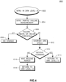
- Figure 3 shows an implicit DRX transition state machine 300 in accordance with one embodiment.
- the state machine 300 may be configured by the eNB (120 of Figure 1 ).
- the state machine 300 may have a life span, also configured by the eNB 120.
- Each state may be applied at the WTRU (110 of Figure 1 ) and at the eNB 120, so that operation is consistent and synchronized.
- a different DRX cycle length is associated with both the WTRU 110 and the eNB 120 operations.
- the DRX cycle length transition rules may be based on WTRU 110 and eNB 120 experiences. Given a certain elapsed time, or a given set of measurement values, the WTRU 110 and the eNB 120 may learn and predict traffic patterns. These learned and predicted traffic patterns may be superimposed on a general model for a state machine, resulting in the DRX state machine 300 for a WTRU 110/eNB 120 system that permits implicit transition operation and consistent DRX actions for both the WTRU 110 and the eNB 120.
- the eNB 120 can prescribe DRX states for service and mobility conditions with the potential for continuous improvement and learned traffic patterns upon every invocation.
- Figure 3 shows 3 defined DRX levels, 302, 304, 306 and an undefined DRX level 308.
- DRX level 3 306 the WTRU 110 is operating in a normal DRX cycle.
- the actual length of the normal state may be defined by the eNB 120.
- DRX level 2 304 is a shorter cycle length than DRX level 3 306, and is associated with more frequent activity than normal.
- the eNB 120 may also define the cycle length for DRX level 2 304, and may also set a "resume" period.
- a resume period is a length of time in which there are no new transmissions and after which the WTRU 110 may return to DRX level 3 306 operation, unless the WTRU 110 is commanded to do otherwise.
- DRX level 1302 has the shortest DRX cycle length, and may be used by a WTRU 110 or eNB 120 to handle predicted immediate downlink commands and when uplink traffic patterns are recognized by the WTRU 110 and the eNB 120 as requiring immediate downlink action, such as during a handover event, for example.
- a DRX level n 308 may be configured with longer DRX cycles than that for the DRX Level 3 306.
- the eNB 120 can redefine the DRX cycle lengths for each state at the end of the DRX configuration life span but may observe a DRX cycle length rule that lower level DRX states have shorter DRX lengths.
- a timer or counter trigger may be defined to trigger a transition to DRX Level 2 304 if the eNB 120 determines that the WTRU 110 should periodically transition to a "busy" cycle to check downlink data. This may be considered a trigger based on a measurement event.
- Another trigger based on a measurement event can also be defined to transition a WTRU 110 from DRX level-3 306 to DRX Level 1 when a traffic volume event on a certain radio bearer accumulating a larger amount of uplink data than a threshold is reported and an anticipated Radio Bearer (RB) Reconfiguration command is imminent.
- RB Radio Bearer
- the WTRU 110 in DRX Level 1 302 state receives a RB Reconfiguration command, the current DRX Level 1 state is over. If the WTRU 110 at DRX Level 1 state 302 does not receive the anticipated command for the defined "resume period", it can go back to its original DRX state and resume the power saving DRX cycle.
- Regular timers and counters may be used during a DRX mode to trigger the implicit DRX cycle length transition. The choice between the timers and counters and the values of the timers or counters may be based on learned traffic patterns and models with respect to the mobility and/or service state of the WTRU 110 at a particular time while the WTRU 110 is in LTE_ACTIVE DRX mode. The timer or counter triggers may be used as transition triggers to bring up the DRX cycle length as well as to bring down the DRX cycle length as the DRX state changes.
- the eNB 120 may configures DRX parameters based on a network traffic monitoring operation and analysis. Several methods exist to select the parameter values, such as by including a default system value set that is defined for implicit DRX transition operation. Optionally, the parameters may be published in system information broadcasts, or they can be determined by the eNB 120 from time to time and loaded to a particular WTRU 110 via higher layer signaling before an intended DRX mode period.
- Transitions between different states may be signaled in an information element.
- An example of a skeleton for signaling an implicit DRX cycle transition if shown in Table 1.
- the Implicit DRX Transition List is mandatory and is limited to a value indicating a maximum number of DRX states.
- the DRX cycle length IE is mandatory, and is an integer.
- the trigger mechanisms are optional, and may be a trigger to move up a DRX state level, or move down a DRX state level.
- the Implicit DRX Transition configured life Span IE is mandatory, and sets the resume period for non-normal states.
- the Initial DRX state is optional, and may set the DRX state of the WTRU 110 at start-up.
- the DRX cycle length definition may be given as a function of the shortest DRX base number ( L). Then various DRX length values may be:
- DRX cycle lengths that are multiples of each other reduces the probability that DRX periods may be mismatched and provides an efficient mechanism to resynchronize DRX periods between the WTRU 110 and eNB 120.
- DRX periods are defined as multiples of each other, and when DRX periods become mismatched between the WTRU 110 and the eNB 120, each entity can determine the period of the other by increasing or decreasing the cycle length to determine the period being used by the other entity, and resynchronizing the entities accordingly.
- a WTRU 110 in DRX Level 1 302 may count n times before it transits back to the original DRX state.
- the network may configure n for the "resume method".
- Transitions from state to state may be initiated by a trigger.
- Table 2 shows an example of transition trigger IEs. Each of the IEs is mandatory, except for the resume period.
- the Transition Trigger is mandatory and is specified by the network if specified as shown in Table 1.
- the CHOICE mechanism allows the network to configure the WTRU 110 for implicit DRX operational triggers.
- the trigger Timer value may be in units of absolute time, LTE frames or transmission time intervals (TTIs) and is used to monitor or regulate ON and OFF periods for network signaling channel activities or data channel activities for the WTRU 110.
- the Counter values may be an integer value used to check the occurrences of certain trigger events.
- the measurement event may enumerate the event that causes the trigger.
- the resume period may be a time period given in seconds, DRX cycles, or some other value, that denotes the total time a WTRU 110 may remain in an elevated state without receiving a command to move back to normal state.
- TABLE 2 Information Element/Group name Need Multi Type and reference Semantics description Transition Trigger MP CHOICE mechanism MP >Timer >> Timer Value MP Integer TBD >Counter >> Counts MP Integer TBD > Measurement Event >> measurement Event-Id MP Enumerated (TBD) >resume period CV-Trigger -UP-2 TBD could be default in Level-1 State. Default is to stay n Level-1 cycles so the total length is equivalent to its original DRX state DRX length
- FIG 4 is a signal flow diagram for implicit DRX transition 400 in accordance with one embodiment.
- a WTRU 402 may receive an RRC message or an IE 406 from the E-UTRAN 404 that triggers the WTRU 402 to enter DRX mode.
- the WTRU 402 may enter DRX mode 408 at a default level which may be a normal cycle length DRX level 3 (306 of Figure 3 ).
- Both the WTRU 402 and the E-UTRAN 404 enter DRX mode (408, 410 respectively).
- the WTRU 402 may receive another RRC message or IE 412 that triggers the WTRU 402 to enter a faster DRX cycle mode (DRX level 1302 of Figure 3 ).
- the WTRU 402 and the E-UTRAN 404 enter the DRX level 1 (414, 416 respectively).
- a WTRU timer 418 synchronized with an E-UTRAN timer (not shown), expires. As the timers are synchronized, no notice of timer expiration is required. The expiration of the timer 418 triggers the WTRU 402 and the E-UTRAN 404 to return to normal DRX level.
- the WTRU 402 returns 422 to DRX level-3 306 at the same time that the E-UTRAN 404 returns 424 to DRX level-3 306.
- FIG. 5 is a flow diagram of a method of implicit signaling 500 in accordance with one embodiment.
- the WTRU is in normal operating mode, or Level-3.
- the WTRU checks to see if a timer has timed-out, or a trigger has been received that would force the WTRU to move to another DRX state. If no, at step 506, the WTRU remains in normal state. If the WTRU detects a time out signal or a trigger at step 504, at step 508, the WTRU determines if it should move to DRX Level 1 or DRX level 2. If the WTRU determines that the trigger is a level-2 trigger, at step 510 the WTRU moves to DRX Level 2.
- the WTRU determines that the resume period has ended, and returns to DRX level-3. If, however, the WTRU, at step 508, determines that it received a level 1 trigger, at step 514, the WTRU goes into a DRX level 1. At step, 516, the WTRU determines if it has received a Radio Bearer Reconfiguration message. If not, the WTRU, at step 518, waits for the resume period to end and returns to normal operation at step 522. If, however, at step 518, the WTRU receives a radio bearer reconfigure message, at step 520, the WTRU returns to normal DRX cycle operation.
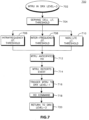
- FIG. 6 is a flow diagram of an implicit DRX method 600 in accordance with another embodiment.
- the WTRU is in normal or DRX Level-3 mode.
- the WTRU conducts a traffic volume measurement.
- the WTRU compares the traffic volume measurement with a threshold. It if the volume is below the threshold, at step 608, the WTRU takes no action and remains in DRX Level-3 mode. However, if, at step 606, the WTRU determines that the traffic is above a threshold, at step 610, the WTRU changes mode to a shorter DRX cycle. Based on the traffic, the new DRX mode may be DRX level-2 or DRX level-1.
- the WTRU determines if a command or message has been received. If yes, at step 614, the WTRU returns to Level-3 mode. If not, the WTRU, at step 616 the WTRU waits the resume period before returning to level-3 mode at step 618.
- the E-UTRAN may determine the traffic volume measurement reporting threshold level for DRX state transition triggering. Once the defined traffic volume measurement event occurs, the DRX state transition is triggered.
- a WTRU may perform traffic volume measurements for uplink traffic.
- the E-UTRAN may configure the WTRU to report the events on threshold crossing. Based on learned traffic patterns, the E-UTRAN determines that there is a large volume change, which may means that an RB addition, an RB reconfiguration or an RB release command is imminent. Therefore, the traffic volume event reports may be used as implicit DRX transition triggers. For example, a large volume change may be used to trigger the WTRU into the shortest DRX cycle (DRX level 1, 302 of Figure 3 , for example) in order to receive the network command.
- DRX level 1, 302 of Figure 3 for example
- the network when receiving the predetermined measurement event, may determine the WTRU's DRX state via implicit DRX transition rules and either sends the anticipated command to the WTRU or wait for the WTRU to return to its previous DRX state with the specified "resume period".
- the WTRU while in LTE_ACTIVE mode, may use configured handover measurements. Certain measurement event reports may indicate that a handover (HO) command is imminent for intra-frequency, inter-frequency or an inter-radio access technology (RAT) handover. Depending on handover measurement events, certain other measurement events may act as triggers for DRX transition control.
- Figure 7 is a flow diagram of a method of implicit DRX signaling 700 in accordance with an alternative embodiment.
- the WTRU is in normal DRX level 3 state.
- the WTRU determines that a serving cell measurement is below a threshold.
- the WTRU may then determine that an intra-frequency measurement is high 706, meaning that an intra-frequency neighbor is measuring as the best cell.
- the WTRU may determine that an inter-frequency band measures to be the best 708.
- the WTRU may determine that a non-LTE system measures the best 710.
- the WTRU due to the measurements, may anticipate a handover command.
- the WTRU reports the measurement event. This may invoke, at step 716, an implicit DRX transition trigger that causes the WTRU to go to a Level-1 DRX state in order to receive the possible handover command from the network.
- the WTRU receives the handover command.
- the WTRU transitions back to its original DRX state.
- FIG. 8 is a flow diagram of a method of implicit DRX cycle signaling 800 in accordance with yet another embodiment.
- the WTRU is level-1 mode.
- the WTRU begins to monitor a Level 1/Level 2 control channel to intercept anticipated downlink commands.
- the WTRU determines if an anticipated network command is received. If received, at step 808, the WTRU will follow the command to end the DRX mode or will receive instruction on the next DRX activity with the command. If the command is not received, at step 810, the WTRU transitions back to its original DRX state before entering the Level-1 state.
- ROM read only memory
- RAM random access memory
- register cache memory
- semiconductor memory devices magnetic media such as internal hard disks and removable disks, magneto-optical media, and optical media such as CD-ROM disks, and digital versatile disks (DVDs).
- Suitable processors include, by way of example, a general purpose processor, a special purpose processor, a conventional processor, a digital signal processor (DSP), a plurality of microprocessors, one or more microprocessors in association with a DSP core, a controller, a microcontroller, Application Specific Integrated Circuits (ASICs), Field Programmable Gate Arrays (FPGAs) circuits, any other type of integrated circuit (IC), and/or a state machine.
- DSP digital signal processor
- ASICs Application Specific Integrated Circuits
- FPGAs Field Programmable Gate Arrays
- a processor in association with software may be used to implement a radio frequency transceiver for use in a wireless transmit receive unit (WTRU), user equipment (UE), terminal, base station, radio network controller (RNC), or any host computer.
- the WTRU may be used in conjunction with modules, implemented in hardware and/or software, such as a camera, a video camera module, a videophone, a speakerphone, a vibration device, a speaker, a microphone, a television transceiver, a hands free headset, a keyboard, a Bluetooth ® module, a frequency modulated (FM) radio unit, a liquid crystal display (LCD) display unit, an organic light-emitting diode (OLED) display unit, a digital music player, a media player, a video game player module, an Internet browser, and/or any wireless local area network (WLAN) module.
- modules implemented in hardware and/or software, such as a camera, a video camera module, a videophone, a speakerphone, a vibration device, a speaker
Landscapes
- Engineering & Computer Science (AREA)
- Computer Networks & Wireless Communication (AREA)
- Signal Processing (AREA)
- Mobile Radio Communication Systems (AREA)
- Transceivers (AREA)
- Transmitters (AREA)
Description
- The present invention is in the field of wireless communications.
- A goal of the Third Generation Partnership Project (3GPP) Long Term Evolution (LTE) program is to develop new technology, new architecture and new methods for settings and configurations in wireless communication systems in order to improve spectral efficiency, reduce latency and better utilize the radio resource to bring faster user experiences and richer applications and services to users with lower costs.
- In a typical LTE network, a wireless transmit/receive unit (WTRU) may operate in a number of modes. While in LTE_ACTIVE mode, the WTRU may operate in a discontinuous reception (DRX) mode. DRX mode allows the WTRU to operate in a low power, or sleep mode, for a preset time, and then switch to a full power, or awake, mode for another preset time in order to reduce battery consumption. The DRX cycle lengths are generally configured by the enhanced universal terrestrial radio access network (E-UTRAN) so that an enhanced Node B (eNB) and the WTRU are synchronized on a consistent sleep and wake-up cycle.
- Live traffic situations and WTRU mobility may require frequent adjustment of the DRX cycle length in order to balance system performance, WTRU performance and WTRU power savings. However, relying only on WTRU/E-UTRAN signaling to make the fine DRX cycle adjustment may incur a heavy system and WTRU signaling load.
- Implicit rules for DRX cycle length adjustment may be used for smooth LTE_ACTIVE DRX operations to reduce battery power consumption while not effecting system or WTRU performance issues. Implicit rules may assist the implicit DRX cycle length transitions between the WTRU and the E-UTRAN without using excessive explicit signaling. "Fast setup for PS services (CELL PCH & URA PCH) ",3GPP DRAFT; R2-063413, XP050133092,
EP 1 613 107 A andUS 2005/148348 A1 disclose WTRUs configured by the network for different (longer, shorter) DRX cycles. - The present invention is disclosed by the appended claims.
- A more detailed understanding may be had from the following description, given by way of example and to be understood in conjunction with the accompanying drawings wherein:
-
Figure 1 shows a wireless communications; -
Figure 2 is a functional block diagram of a WTRU and an e Node B (eNB); -
Figure 3 is a state diagram of implicit DRX transition; -
Figure 4 is a signal flow diagram for implicit DRX transition; -
Figure 5 is a flow diagram for a method of implicit DRX signaling; -
Figure 6 is a flow diagram for a method of implicit DRX signaling; -
Figure 7 is a flow diagram for a method of implicit DRX signaling; -
Figure 8 is a flow diagram for a method of implicit DRX signaling. - When referred to hereafter, the terminology "wireless transmit/receive unit (WTRU)" includes but is not limited to a user equipment (UE), a mobile station, a fixed or mobile subscriber unit, a pager, a cellular telephone, a personal digital assistant (PDA), a computer, or any other type of user device capable of operating in a wireless environment. When referred to hereafter, the terminology "base station" includes but is not limited to a Node-B, a site controller, an access point (AP), or any other type of interfacing device capable of operating in a wireless environment.
-
Figure 1 shows awireless communication system 100 in accordance with one embodiment. Thesystem 100 includes a plurality of WTRUs 110 and an eNB 120. As shown inFigure 1 , the WTRUs 110 are in communication with the eNB 120. Although three WTRUs 110 and one eNB 120 are shown inFigure 1 , it should be noted that any combination of wireless and wired devices may be included in thewireless communication system 100. The eNB 120 and the WTRUs 110 may communicate while in DRX mode and may have coordinated DRX cycles. -
Figure 2 is a functional block diagram 200 of a WTRU 110 and the eNB 120 of thewireless communication system 100 ofFigure 1 . As shown inFigure 1 , the WTRU 110 is in communication with the eNB 120. Both WTRU 110 and eNB 120 may operate in DRX mode. - In addition to the components that may be found in a typical WTRU, the WTRU 110 includes a
processor 215, areceiver 216, atransmitter 217, and anantenna 218. Theprocessor 215 may be configured to adjust DRX cycle length as necessary. Thereceiver 216 and thetransmitter 217 are in communication with theprocessor 215. Theantenna 218 is in communication with both thereceiver 216 and thetransmitter 217 to facilitate the transmission and reception of wireless data. - In addition to the components that may be found in a typical eNB 120, the eNB 120 includes a
processor 225, areceiver 226, atransmitter 227, and anantenna 228. Theprocessor 225 is configured to communicate with thereceiver 226 andtransmitter 227 to adjust DRX cycles as necessary. Thereceiver 226 and thetransmitter 227 are in communication with theprocessor 225. Theantenna 228 is in communication with both thereceiver 226 and thetransmitter 227 to facilitate the transmission and reception of wireless data. - In order to improve battery life, but not limit the eNB 120 and WTRU 110 performance, transitions between DRX cycle length states may be defined implicitly, rather than explicitly. The implicit rules may be implemented at the radio resource control (RRC) and the medium access control (MAC) levels while the WTRU 110 is in a LTE_ACTIVE DRX state.
- Approximately half of
WTRU 110 to eNB 120 interaction involves WTRU 110 requests and reports andeNB 120 responses while theWTRU 110 is in LTE_ACTIVE DRX mode. When the WTRU 110 measures a particular scenario, measurement events may be reported to the eNB 120, and the eNB 120 may respond to the situation by commanding the WTRU 110 to start a new service, mobility activity, and the like. If the downlink command transmission or reception is limited by a relatively long DRX cycle length, WTRU 110 and eNB 120 system performance during LTE_ACTIVE DRX mode may suffer. However, certain measurement events may make good candidates for the anticipated network downlink commands. -
Figure 3 shows an implicit DRXtransition state machine 300 in accordance with one embodiment. Thestate machine 300, as well as associated transition mechanisms and parameter values, may be configured by the eNB (120 ofFigure 1 ). Thestate machine 300 may have a life span, also configured by the eNB 120. Each state may be applied at the WTRU (110 ofFigure 1 ) and at theeNB 120, so that operation is consistent and synchronized. At each defined and configured DRX state, a different DRX cycle length is associated with both the WTRU 110 and the eNB 120 operations. - The DRX cycle length transition rules may be based on WTRU 110 and eNB 120 experiences. Given a certain elapsed time, or a given set of measurement values, the WTRU 110 and the eNB 120 may learn and predict traffic patterns. These learned and predicted traffic patterns may be superimposed on a general model for a state machine, resulting in the
DRX state machine 300 for a WTRU 110/eNB 120 system that permits implicit transition operation and consistent DRX actions for both the WTRU 110 and the eNB 120. The eNB 120 can prescribe DRX states for service and mobility conditions with the potential for continuous improvement and learned traffic patterns upon every invocation. -
Figure 3 shows 3 defined DRX levels, 302, 304, 306 and anundefined DRX level 308. InDRX level 3 306, the WTRU 110 is operating in a normal DRX cycle. The actual length of the normal state may be defined by the eNB 120.DRX level 2 304 is a shorter cycle length thanDRX level 3 306, and is associated with more frequent activity than normal. The eNB 120 may also define the cycle length forDRX level 2 304, and may also set a "resume" period. A resume period is a length of time in which there are no new transmissions and after which the WTRU 110 may return toDRX level 3 306 operation, unless the WTRU 110 is commanded to do otherwise. - DRX level 1302 has the shortest DRX cycle length, and may be used by a
WTRU 110 oreNB 120 to handle predicted immediate downlink commands and when uplink traffic patterns are recognized by theWTRU 110 and theeNB 120 as requiring immediate downlink action, such as during a handover event, for example. - A
DRX level n 308 may be configured with longer DRX cycles than that for theDRX Level 3 306. TheeNB 120 can redefine the DRX cycle lengths for each state at the end of the DRX configuration life span but may observe a DRX cycle length rule that lower level DRX states have shorter DRX lengths. - For a
WTRU 110 atDRX level 3 306, a timer or counter trigger may be defined to trigger a transition toDRX Level 2 304 if theeNB 120 determines that theWTRU 110 should periodically transition to a "busy" cycle to check downlink data. This may be considered a trigger based on a measurement event. Another trigger based on a measurement event can also be defined to transition aWTRU 110 from DRX level-3 306 toDRX Level 1 when a traffic volume event on a certain radio bearer accumulating a larger amount of uplink data than a threshold is reported and an anticipated Radio Bearer (RB) Reconfiguration command is imminent. - If the
WTRU 110 inDRX Level 1 302 state receives a RB Reconfiguration command, thecurrent DRX Level 1 state is over. If theWTRU 110 atDRX Level 1state 302 does not receive the anticipated command for the defined "resume period", it can go back to its original DRX state and resume the power saving DRX cycle. Regular timers and counters may be used during a DRX mode to trigger the implicit DRX cycle length transition. The choice between the timers and counters and the values of the timers or counters may be based on learned traffic patterns and models with respect to the mobility and/or service state of theWTRU 110 at a particular time while theWTRU 110 is in LTE_ACTIVE DRX mode. The timer or counter triggers may be used as transition triggers to bring up the DRX cycle length as well as to bring down the DRX cycle length as the DRX state changes. - The
eNB 120 may configures DRX parameters based on a network traffic monitoring operation and analysis. Several methods exist to select the parameter values, such as by including a default system value set that is defined for implicit DRX transition operation. Optionally, the parameters may be published in system information broadcasts, or they can be determined by theeNB 120 from time to time and loaded to aparticular WTRU 110 via higher layer signaling before an intended DRX mode period. - Transitions between different states may be signaled in an information element. An example of a skeleton for signaling an implicit DRX cycle transition if shown in Table 1. As shown in Table 1, the Implicit DRX Transition List is mandatory and is limited to a value indicating a maximum number of DRX states.
- The DRX cycle length IE is mandatory, and is an integer. The trigger mechanisms are optional, and may be a trigger to move up a DRX state level, or move down a DRX state level. The Implicit DRX Transition configured life Span IE is mandatory, and sets the resume period for non-normal states. The Initial DRX state is optional, and may set the DRX state of the
WTRU 110 at start-up. - To aid with easier DRX cycle length transition and maintain DRX cycle length synchronization between the
WTRU 110 and theeNB 120, the DRX cycle length definition may be given as a function of the shortest DRX base number ( L). Then various DRX length values may be: - DRX-cycle-len = L x 2n, Equation(1) where n = 0, 1, 2... such that the resulting DRX-cycle-len does not exceed a maximum DRX cycle length. The shortest DRX cycle length possible occurs when n=0, and is a fraction of a longer DRX cycle length.
- The use of DRX cycle lengths that are multiples of each other reduces the probability that DRX periods may be mismatched and provides an efficient mechanism to resynchronize DRX periods between the
WTRU 110 andeNB 120. When DRX periods are defined as multiples of each other, and when DRX periods become mismatched between theWTRU 110 and theeNB 120, each entity can determine the period of the other by increasing or decreasing the cycle length to determine the period being used by the other entity, and resynchronizing the entities accordingly. - Typically, a
WTRU 110 inDRX Level 1 302 may count n times before it transits back to the original DRX state. The default may be given as: n = (Level-k DRX Cycle Length or original DRX cycle length) / Level-1 DRX Cycle Length; where Level-k cycle length is the length of the DRX cycle before theWTRU 110 enters DRX Level 1302. Alternatively, the network may configure n for the "resume method".TABLE 1 Information Element/Group name Need Multi Type and reference Semantics description Implicit DRX Transition List MP maxDR Xstates (TBD) >DRX Cycle Length MP Integer (TBD) >Trigger-UP-1 OP Trigger Mechanism A.B.C.D To next upper level DRX State >Trigger-UP-2 OP Trigger Mechanism A.B.C.D Used by Level-1 for resume >Trigger-Down-1 OP Trigger Mechanism A.B.C.D To next lower level DRX state >Trigger-Down-2 OP Trigger Mechanism A.B.C.D To Level-1 trigger Implicit DRX Transition configured life span MP TBD Time in seconds Initial DRX state OP TBD - Transitions from state to state may be initiated by a trigger. Table 2 shows an example of transition trigger IEs. Each of the IEs is mandatory, except for the resume period. The Transition Trigger is mandatory and is specified by the network if specified as shown in Table 1. The CHOICE mechanism allows the network to configure the
WTRU 110 for implicit DRX operational triggers. The trigger Timer value may be in units of absolute time, LTE frames or transmission time intervals (TTIs) and is used to monitor or regulate ON and OFF periods for network signaling channel activities or data channel activities for theWTRU 110. The Counter values may be an integer value used to check the occurrences of certain trigger events. The measurement event may enumerate the event that causes the trigger. The resume period may be a time period given in seconds, DRX cycles, or some other value, that denotes the total time aWTRU 110 may remain in an elevated state without receiving a command to move back to normal state.TABLE 2 Information Element/Group name Need Multi Type and reference Semantics description Transition Trigger MP CHOICE mechanism MP >Timer >> Timer Value MP Integer TBD >Counter >> Counts MP Integer TBD > Measurement Event >> measurement Event-Id MP Enumerated (TBD) >resume period CV-Trigger -UP-2 TBD Could be default in Level-1 State. Default is to stay n Level-1 cycles so the total length is equivalent to its original DRX state DRX length -
Figure 4 is a signal flow diagram forimplicit DRX transition 400 in accordance with one embodiment. AWTRU 402 may receive an RRC message or anIE 406 from the E-UTRAN 404 that triggers theWTRU 402 to enter DRX mode. TheWTRU 402 may enterDRX mode 408 at a default level which may be a normal cycle length DRX level 3 (306 ofFigure 3 ). Both theWTRU 402 and the E-UTRAN 404 enter DRX mode (408, 410 respectively). TheWTRU 402 may receive another RRC message orIE 412 that triggers theWTRU 402 to enter a faster DRX cycle mode (DRX level 1302 ofFigure 3 ). TheWTRU 402 and the E-UTRAN 404 enter the DRX level 1 (414, 416 respectively). AWTRU timer 418, synchronized with an E-UTRAN timer (not shown), expires. As the timers are synchronized, no notice of timer expiration is required. The expiration of thetimer 418 triggers theWTRU 402 and the E-UTRAN 404 to return to normal DRX level. TheWTRU 402 returns 422 to DRX level-3 306 at the same time that the E-UTRAN 404 returns 424 to DRX level-3 306. -
Figure 5 is a flow diagram of a method ofimplicit signaling 500 in accordance with one embodiment. Atstep 502 the WTRU is in normal operating mode, or Level-3. Atstep 504, the WTRU checks to see if a timer has timed-out, or a trigger has been received that would force the WTRU to move to another DRX state. If no, atstep 506, the WTRU remains in normal state. If the WTRU detects a time out signal or a trigger atstep 504, atstep 508, the WTRU determines if it should move toDRX Level 1 orDRX level 2. If the WTRU determines that the trigger is a level-2 trigger, atstep 510 the WTRU moves toDRX Level 2. Atstep 512, the WTRU determines that the resume period has ended, and returns to DRX level-3. If, however, the WTRU, atstep 508, determines that it received alevel 1 trigger, atstep 514, the WTRU goes into aDRX level 1. At step, 516, the WTRU determines if it has received a Radio Bearer Reconfiguration message. If not, the WTRU, atstep 518, waits for the resume period to end and returns to normal operation atstep 522. If, however, atstep 518, the WTRU receives a radio bearer reconfigure message, atstep 520, the WTRU returns to normal DRX cycle operation. -
Figure 6 is a flow diagram of animplicit DRX method 600 in accordance with another embodiment. Atstep 602, the WTRU is in normal or DRX Level-3 mode. Atstep 604, the WTRU conducts a traffic volume measurement. Atstep 606, the WTRU compares the traffic volume measurement with a threshold. It if the volume is below the threshold, atstep 608, the WTRU takes no action and remains in DRX Level-3 mode. However, if, atstep 606, the WTRU determines that the traffic is above a threshold, atstep 610, the WTRU changes mode to a shorter DRX cycle. Based on the traffic, the new DRX mode may be DRX level-2 or DRX level-1. Atstep 612, the WTRU determines if a command or message has been received. If yes, atstep 614, the WTRU returns to Level-3 mode. If not, the WTRU, atstep 616 the WTRU waits the resume period before returning to level-3 mode atstep 618. Optionally, the E-UTRAN may determine the traffic volume measurement reporting threshold level for DRX state transition triggering. Once the defined traffic volume measurement event occurs, the DRX state transition is triggered. - While in LTE_ACTIVE DRX mode, a WTRU may perform traffic volume measurements for uplink traffic. The E-UTRAN may configure the WTRU to report the events on threshold crossing. Based on learned traffic patterns, the E-UTRAN determines that there is a large volume change, which may means that an RB addition, an RB reconfiguration or an RB release command is imminent. Therefore, the traffic volume event reports may be used as implicit DRX transition triggers. For example, a large volume change may be used to trigger the WTRU into the shortest DRX cycle (
DRX level Figure 3 , for example) in order to receive the network command. The network, when receiving the predetermined measurement event, may determine the WTRU's DRX state via implicit DRX transition rules and either sends the anticipated command to the WTRU or wait for the WTRU to return to its previous DRX state with the specified "resume period". - By way of another example, the WTRU, while in LTE_ACTIVE mode, may use configured handover measurements. Certain measurement event reports may indicate that a handover (HO) command is imminent for intra-frequency, inter-frequency or an inter-radio access technology (RAT) handover. Depending on handover measurement events, certain other measurement events may act as triggers for DRX transition control.
Figure 7 is a flow diagram of a method of implicit DRX signaling 700 in accordance with an alternative embodiment. Atstep 702, the WTRU is innormal DRX level 3 state. Atstep 704, the WTRU determines that a serving cell measurement is below a threshold. The WTRU may then determine that an intra-frequency measurement is high 706, meaning that an intra-frequency neighbor is measuring as the best cell. Alternatively, the WTRU may determine that an inter-frequency band measures to be the best 708. As another alternative, the WTRU may determine that a non-LTE system measures the best 710. - At
step 712, the WTRU, due to the measurements, may anticipate a handover command. Atstep 714, the WTRU reports the measurement event. This may invoke, atstep 716, an implicit DRX transition trigger that causes the WTRU to go to a Level-1 DRX state in order to receive the possible handover command from the network. Atstep 718, the WTRU receives the handover command. Atstep 720, the WTRU transitions back to its original DRX state. -
Figure 8 is a flow diagram of a method of implicit DRX cycle signaling 800 in accordance with yet another embodiment. Atstep 802, the WTRU is level-1 mode. Atstep 804, the WTRU begins to monitor aLevel 1/Level 2 control channel to intercept anticipated downlink commands. Atstep 806, the WTRU determines if an anticipated network command is received. If received, atstep 808, the WTRU will follow the command to end the DRX mode or will receive instruction on the next DRX activity with the command. If the command is not received, atstep 810, the WTRU transitions back to its original DRX state before entering the Level-1 state. - Although the features and elements are described in the embodiments in particular combinations, each feature or element can be used alone without the other features and elements or in various combinations with or without other features and elements. The methods or flow charts provided may be implemented in a computer program, software, or firmware tangibly embodied in a computer-readable storage medium for execution by a general purpose computer or a processor. Examples of computer-readable storage mediums include a read only memory (ROM), a random access memory (RAM), a register, cache memory, semiconductor memory devices, magnetic media such as internal hard disks and removable disks, magneto-optical media, and optical media such as CD-ROM disks, and digital versatile disks (DVDs).
- Suitable processors include, by way of example, a general purpose processor, a special purpose processor, a conventional processor, a digital signal processor (DSP), a plurality of microprocessors, one or more microprocessors in association with a DSP core, a controller, a microcontroller, Application Specific Integrated Circuits (ASICs), Field Programmable Gate Arrays (FPGAs) circuits, any other type of integrated circuit (IC), and/or a state machine.
- A processor in association with software may be used to implement a radio frequency transceiver for use in a wireless transmit receive unit (WTRU), user equipment (UE), terminal, base station, radio network controller (RNC), or any host computer. The WTRU may be used in conjunction with modules, implemented in hardware and/or software, such as a camera, a video camera module, a videophone, a speakerphone, a vibration device, a speaker, a microphone, a television transceiver, a hands free headset, a keyboard, a Bluetooth® module, a frequency modulated (FM) radio unit, a liquid crystal display (LCD) display unit, an organic light-emitting diode (OLED) display unit, a digital music player, a media player, a video game player module, an Internet browser, and/or any wireless local area network (WLAN) module.
Claims (17)
- A method implemented by a wireless transmit/receive unit, WTRU (110) for controlling discontinuous reception, DRX, the method comprising:receiving higher layer signaling comprising DRX parameters for a first DRX level associated with a first DRX cycle length, a second DRX level associated with a second DRX cycle length, and an indication of a resume period, wherein the indication of a resume period indicates a number of DRX cycles at which the WTRU is to perform DRX using the first DRX cycle length prior to implicitly transitioning to performing DRX using the second DRX cycle length if no new transmissions are received;performing DRX using the second DRX cycle length;performing DRX using the first DRX cycle length based on a trigger;determining that the WTRU has performed DRX using the first DRX cycle length for the number of DRX cycles indicated by the resume period without receiving a new transmission; andtransitioning the WTRU from performing DRX using the first DRX cycle length to performing DRX using the second DRX cycle length based on determining that the WTRU has performed DRX using the first DRX cycle length for the determined number of DRX cycles indicated by the resume period without receiving a new transmission, wherein the second DRX cycle length is a multiple of the first DRX cycle length.
- The method as in claim 1, wherein the resume period is synchronized with a base station.
- The method as in claim 1, further comprising monitoring a control channel for reception of downlink commands.
- The method as in claim 1, wherein a command received on a control channel causes the WTRU to change its DRX cycle length.
- The method as in claim 1, wherein the DRX operation is implemented at a medium access control, MAC, level.
- The method as in claim 1, wherein the higher layer signaling comprises radio resource control, RRC, signaling.
- The method as in claim 1, wherein the trigger comprises expiration of a timer.
- The method as in claim 1, wherein the trigger comprises a downlink command.
- A wireless transmit/receive unit, WTRU (110) comprising:means for receiving higher layer signaling comprising DRX parameters for a first DRX level associated with a first DRX cycle length, a second DRX level associated with a second DRX cycle length, and an indication of a resume period, wherein the indication of a resume period indicates a number of DRX cycles at which the WTRU is to perform DRX using the first DRX cycle length prior to implicitly transitioning to performing DRX using the second DRX cycle length if no new transmissions are received;means for performing DRX using the second DRX cycle length;means for performing DRX using the first DRX cycle length based on a trigger;means for determining that the WTRU has performed DRX using the first DRX cycle length for the number of DRX cycles indicated by the resume period without receiving a new transmission; andmeans for transitioning the WTRU from performing DRX using the first DRX cycle length to performing DRX using the second DRX cycle length based on determining that the WTRU has performed DRX using the first DRX cycle length for the determined number of DRX cycles indicated by the resume period without receiving a new transmission, wherein the second DRX cycle length is a multiple of the first DRX cycle length.
- The WTRU as in claim 9, wherein the resume period is synchronized with a base station.
- The WTRU as in claim 9, further comprising means for monitoring a control channel for reception of downlink commands.
- The WTRU as in claim 9, wherein a command received on a control channel causes the WTRU to change its DRX cycle length.
- The WTRU as in claim 9, wherein the DRX operation is implemented at a medium access control, MAC, level.
- The WTRU as in claim 9, wherein the higher layer signaling comprises radio resource control, RRC, signaling.
- The WTRU as in claim 9, wherein the trigger comprises expiration of a timer.
- The WTRU as in claim 9, wherein the trigger comprises a downlink command.
- A network device comprising:means for sending higher layer signaling to a wireless transmit/receive unit, WTRU, the higher layer signaling comprising DRX parameters for a first DRX level associated with a first DRX cycle length, a second DRX level associated with a second DRX cycle length, and an indication of a resume period, wherein the indication of a resume period indicates a number of DRX cycles at which the WTRU is to perform DRX using the first DRX cycle length prior to implicitly transitioning to performing DRX using the second DRX cycle length if no new transmissions are received;means for sending a trigger to the WTRU, the trigger causing the WTRU to perform DRX using the first DRX cycle length;means for determining that the WTRU has performed DRX using the first DRX cycle length for the number of DRX cycles indicated by the resume period without receiving a new transmission; andmeans for determining that the WTRU has transitioned from performing DRX using the first DRX cycle length to performing DRX using the second DRX cycle based on determining that the WTRU has performed DRX using the first DRX cycle length for the determined number of DRX cycles indicated by the resume period without receiving a new transmission, wherein the second DRX cycle length is a multiple of the first DRX cycle length.
Priority Applications (1)
| Application Number | Priority Date | Filing Date | Title |
|---|---|---|---|
| EP23178469.5A EP4236602A1 (en) | 2007-01-30 | 2008-01-30 | Implicit drx cycle length adjustment control in lte_active mode |
Applications Claiming Priority (5)
| Application Number | Priority Date | Filing Date | Title |
|---|---|---|---|
| US88727607P | 2007-01-30 | 2007-01-30 | |
| EP08713371.6A EP2127420B1 (en) | 2007-01-30 | 2008-01-30 | Implicit drx cycle length adjustment control in lte_active mode |
| PCT/US2008/001344 WO2008094681A1 (en) | 2007-01-30 | 2008-01-30 | Implicit drx cycle length adjustment control in lte_active mode |
| EP15177661.4A EP2958395B1 (en) | 2007-01-30 | 2008-01-30 | Implicit drx cycle length adjustment control in lte_active mode |
| EP17203983.6A EP3310115B1 (en) | 2007-01-30 | 2008-01-30 | Implicit drx cycle length adjustment control in lte_active mode |
Related Parent Applications (4)
| Application Number | Title | Priority Date | Filing Date |
|---|---|---|---|
| EP15177661.4A Division EP2958395B1 (en) | 2007-01-30 | 2008-01-30 | Implicit drx cycle length adjustment control in lte_active mode |
| EP08713371.6A Division EP2127420B1 (en) | 2007-01-30 | 2008-01-30 | Implicit drx cycle length adjustment control in lte_active mode |
| EP17203983.6A Division EP3310115B1 (en) | 2007-01-30 | 2008-01-30 | Implicit drx cycle length adjustment control in lte_active mode |
| EP17203983.6A Division-Into EP3310115B1 (en) | 2007-01-30 | 2008-01-30 | Implicit drx cycle length adjustment control in lte_active mode |
Related Child Applications (2)
| Application Number | Title | Priority Date | Filing Date |
|---|---|---|---|
| EP23178469.5A Division-Into EP4236602A1 (en) | 2007-01-30 | 2008-01-30 | Implicit drx cycle length adjustment control in lte_active mode |
| EP23178469.5A Division EP4236602A1 (en) | 2007-01-30 | 2008-01-30 | Implicit drx cycle length adjustment control in lte_active mode |
Publications (2)
| Publication Number | Publication Date |
|---|---|
| EP3840523A1 EP3840523A1 (en) | 2021-06-23 |
| EP3840523B1 true EP3840523B1 (en) | 2023-11-15 |
Family
ID=39540680
Family Applications (7)
| Application Number | Title | Priority Date | Filing Date |
|---|---|---|---|
| EP12170399.5A Ceased EP2574136B1 (en) | 2007-01-30 | 2008-01-30 | Implicit DRX cycle length adjustment control in LTE active mode |
| EP08713371.6A Active EP2127420B1 (en) | 2007-01-30 | 2008-01-30 | Implicit drx cycle length adjustment control in lte_active mode |
| EP17203983.6A Active EP3310115B1 (en) | 2007-01-30 | 2008-01-30 | Implicit drx cycle length adjustment control in lte_active mode |
| EP21155851.5A Active EP3840523B1 (en) | 2007-01-30 | 2008-01-30 | Implicit drx cycle length adjustment control in lte_active mode |
| EP15177661.4A Active EP2958395B1 (en) | 2007-01-30 | 2008-01-30 | Implicit drx cycle length adjustment control in lte_active mode |
| EP23178469.5A Pending EP4236602A1 (en) | 2007-01-30 | 2008-01-30 | Implicit drx cycle length adjustment control in lte_active mode |
| EP12170412.6A Not-in-force EP2568762B1 (en) | 2007-01-30 | 2008-01-30 | Implicit DRX cycle length adjustment control in LTE active mode |
Family Applications Before (3)
| Application Number | Title | Priority Date | Filing Date |
|---|---|---|---|
| EP12170399.5A Ceased EP2574136B1 (en) | 2007-01-30 | 2008-01-30 | Implicit DRX cycle length adjustment control in LTE active mode |
| EP08713371.6A Active EP2127420B1 (en) | 2007-01-30 | 2008-01-30 | Implicit drx cycle length adjustment control in lte_active mode |
| EP17203983.6A Active EP3310115B1 (en) | 2007-01-30 | 2008-01-30 | Implicit drx cycle length adjustment control in lte_active mode |
Family Applications After (3)
| Application Number | Title | Priority Date | Filing Date |
|---|---|---|---|
| EP15177661.4A Active EP2958395B1 (en) | 2007-01-30 | 2008-01-30 | Implicit drx cycle length adjustment control in lte_active mode |
| EP23178469.5A Pending EP4236602A1 (en) | 2007-01-30 | 2008-01-30 | Implicit drx cycle length adjustment control in lte_active mode |
| EP12170412.6A Not-in-force EP2568762B1 (en) | 2007-01-30 | 2008-01-30 | Implicit DRX cycle length adjustment control in LTE active mode |
Country Status (22)
| Country | Link |
|---|---|
| US (8) | US8238260B2 (en) |
| EP (7) | EP2574136B1 (en) |
| JP (4) | JP5475466B2 (en) |
| KR (6) | KR101293812B1 (en) |
| CN (2) | CN101682888B (en) |
| AR (1) | AR065086A1 (en) |
| AU (1) | AU2008210980A1 (en) |
| BR (1) | BRPI0806385B1 (en) |
| CA (1) | CA2677074C (en) |
| DK (1) | DK2958395T3 (en) |
| ES (3) | ES2966379T3 (en) |
| FI (1) | FI3840523T3 (en) |
| HK (1) | HK1219379A1 (en) |
| IL (1) | IL200180A (en) |
| MX (1) | MX2009008111A (en) |
| MY (1) | MY151801A (en) |
| NO (1) | NO2958395T3 (en) |
| PL (1) | PL2958395T3 (en) |
| RU (2) | RU2433567C2 (en) |
| SG (1) | SG177986A1 (en) |
| TW (3) | TWI558247B (en) |
| WO (1) | WO2008094681A1 (en) |
Families Citing this family (155)
| Publication number | Priority date | Publication date | Assignee | Title |
|---|---|---|---|---|
| EP2005619A2 (en) | 2006-03-24 | 2008-12-24 | Interdigital Technology Corporation | Method and apparatus for maintaining uplink synchronization and reducing battery power consumption |
| KR101265643B1 (en) * | 2006-08-22 | 2013-05-22 | 엘지전자 주식회사 | A mothod of executing handover and controlling thereof in mobile communication system |
| KR101387500B1 (en) | 2006-08-22 | 2014-04-21 | 엘지전자 주식회사 | Method of transmitting and receiving control information in wireless communicaiton system |
| EP2070368B1 (en) * | 2006-10-02 | 2016-07-06 | LG Electronics Inc. | Method for transmitting and receiving paging message in wireless communication system |
| KR101443618B1 (en) | 2006-10-30 | 2014-09-23 | 엘지전자 주식회사 | Method for transmitting random access channel message and response message, and Mobile communication terminal |
| JP4523072B2 (en) * | 2006-10-30 | 2010-08-11 | エルジー エレクトロニクス インコーポレイティド | Redirection method for uplink connection |
| EP2084928B1 (en) | 2006-10-30 | 2017-08-23 | LG Electronics Inc. | Method of performing random access in a wireless communication system |
| KR100938754B1 (en) * | 2006-10-30 | 2010-01-26 | 엘지전자 주식회사 | Data transmission method and data receiving method using discontinuous reception |
| FI3840523T3 (en) * | 2007-01-30 | 2024-01-03 | Interdigital Tech Corp | Implicit drx cycle length adjustment control in lte_active mode |
| US20090023448A1 (en) * | 2007-02-21 | 2009-01-22 | Qualcomm Incorporated | Method and apparatus for inter-system handover |
| US20100034145A1 (en) * | 2007-03-15 | 2010-02-11 | Samsung Electronics Co., Ltd. | Method for receiving packet in mobile communication system |
| US8020075B2 (en) | 2007-03-16 | 2011-09-13 | Apple Inc. | Channel quality index feedback reduction for broadband systems |
| US8023467B2 (en) * | 2007-04-27 | 2011-09-20 | Research In Motion Limited | Method and system for efficient DRX operation during handover in LTE |
| US20080267168A1 (en) * | 2007-04-27 | 2008-10-30 | Zhijun Cai | Slow Adaptation of Modulation and Coding for Packet Transmission |
| EP2132910B1 (en) * | 2007-04-30 | 2016-01-06 | LG Electronics Inc. | Method of transmitting data in a wireless communication system |
| US8040806B2 (en) * | 2007-04-30 | 2011-10-18 | Lg Electronics Inc. | Methods of generating data block in mobile communication system |
| KR101458641B1 (en) * | 2007-04-30 | 2014-11-05 | 엘지전자 주식회사 | Method of transmitting data in wireless communication system supporting multimedia broadcast/multicast service |
| KR101469281B1 (en) * | 2007-04-30 | 2014-12-04 | 엘지전자 주식회사 | Method for state transition of mobile terminal |
| KR101464748B1 (en) * | 2007-04-30 | 2014-11-24 | 엘지전자 주식회사 | Method for triggering a measurement report of mobile terminal |
| EP2137910B1 (en) * | 2007-04-30 | 2015-07-08 | LG Electronics Inc. | Methods of transmitting data blocks in wireless communication system |
| KR101461236B1 (en) * | 2007-04-30 | 2014-11-12 | 엘지전자 주식회사 | Methods for performing an Authentication of entities during establishment of wireless call connection |
| US8218524B2 (en) * | 2007-04-30 | 2012-07-10 | Lg Electronics Inc. | Method for transmitting or receiving data unit using header field existence indicator |
| KR20080097338A (en) * | 2007-05-01 | 2008-11-05 | 엘지전자 주식회사 | Discontinuous data transmittion/reception method |
| KR100917205B1 (en) * | 2007-05-02 | 2009-09-15 | 엘지전자 주식회사 | Method of configuring a data block in wireless communication system |
| US20080273482A1 (en) * | 2007-05-02 | 2008-11-06 | Lg Electronics Inc. | Uplink access method for receiving a point-to-multipoint service |
| US20080273503A1 (en) * | 2007-05-02 | 2008-11-06 | Lg Electronics Inc. | Method and terminal for performing handover in mobile communications system of point-to-multipoint service |
| WO2008136598A1 (en) * | 2007-05-03 | 2008-11-13 | Lg Electronics Inc. | Method of data processing in a wireless communication system |
| EP2538614B1 (en) * | 2007-06-15 | 2014-06-11 | BlackBerry Limited | System and method for semi-persistent and dynamic scheduling and discontinuous reception control |
| WO2008151411A1 (en) * | 2007-06-15 | 2008-12-18 | Research In Motion Limited | System and method for large packet delivery during semi persistently allocated session |
| CN101682857B (en) * | 2007-06-15 | 2013-10-30 | 捷讯研究有限公司 | System and method for link adaptation overhead reduction |
| KR101526971B1 (en) * | 2007-06-18 | 2015-06-11 | 엘지전자 주식회사 | Method for transmitting/receiving broadcast or multicast service and terminal thereof |
| ES2428569T3 (en) | 2007-06-18 | 2013-11-08 | Lg Electronics Inc. | Procedure for performing uplink synchronization in a wireless communication system |
| WO2008156308A2 (en) * | 2007-06-18 | 2008-12-24 | Lg Electronics Inc. | Paging information transmission method for effective call setup |
| US8139524B2 (en) * | 2007-06-18 | 2012-03-20 | Lg Electronics Inc. | Control channel reception method for receiving broadcast or multicast service |
| KR101470638B1 (en) * | 2007-06-18 | 2014-12-08 | 엘지전자 주식회사 | Method for enhancing radio resource and informing status report in mobile telecommunications system and receiver of mobile telecommunications |
| KR101829565B1 (en) * | 2007-07-23 | 2018-03-29 | 더 차이니즈 유니버시티 오브 홍콩 | Determining a nucleic acid sequence imbalance |
| CN101772928B (en) | 2007-08-03 | 2016-08-24 | 交互数字专利控股公司 | For discontinuous reception, cell reselection and the system level information of RACH |
| US20090046639A1 (en) * | 2007-08-14 | 2009-02-19 | Zhijun Cai | System and Method for Handling Large IP Packets During VoIP Session |
| EP2346198B1 (en) | 2007-08-20 | 2020-02-12 | BlackBerry Limited | System and method for DRX control and NACK/ACK |
| ATE536066T1 (en) | 2007-09-14 | 2011-12-15 | Research In Motion Ltd | SYSTEM AND METHOD FOR CONTROLLING DISCONTINUOUS RECEIPT START TIME |
| US8400982B2 (en) * | 2007-09-20 | 2013-03-19 | Lg Electronics Inc. | Method for handling correctly received but header compression failed packets |
| KR101387537B1 (en) * | 2007-09-20 | 2014-04-21 | 엘지전자 주식회사 | A method for handling correctly received but header compression failed packets |
| US8451803B2 (en) * | 2007-10-05 | 2013-05-28 | Qualcomm Incorporated | Methods and apparatus for managing measurement behavior of DRX mode UE |
| US20100330920A1 (en) * | 2007-10-30 | 2010-12-30 | Nokia Corporation | Providing improved connection failure detection |
| EP2232722B1 (en) * | 2008-01-17 | 2017-06-21 | Telefonaktiebolaget LM Ericsson (publ) | Method and arrangement for handling a radio receiver in a wireless communication network |
| US8606336B2 (en) | 2008-03-20 | 2013-12-10 | Blackberry Limited | System and method for uplink timing synchronization in conjunction with discontinuous reception |
| WO2009117634A1 (en) * | 2008-03-21 | 2009-09-24 | Research In Motion Limited | Method and system for configuring a long drx cycle in a lte ( e-utra) mobile communications network |
| US8526377B2 (en) * | 2008-03-25 | 2013-09-03 | Telefonaktiebolaget Lm Ericsson (Publ) | DRX functionality in multi-carrier wireless networks |
| US9313720B2 (en) | 2008-03-27 | 2016-04-12 | Qualcomm Incorporated | Power efficient small base station scanning and acquisition |
| JP5367810B2 (en) | 2008-04-25 | 2013-12-11 | ブラックベリー リミテッド | Method and system for control of discontinuous reception in a wireless network |
| US8774133B2 (en) * | 2008-05-02 | 2014-07-08 | Mediatek Inc. | Method of cell measurement based on cell reselection and measured report in UMTS cellular system |
| WO2009148366A1 (en) * | 2008-06-02 | 2009-12-10 | Telefonaktiebolaget L M Ericsson (Publ) | Gating control loop |
| US9386431B2 (en) | 2008-08-05 | 2016-07-05 | Qualcomm Incorporated | Battery efficient method to search for preferred femtocell |
| CN101656978B (en) | 2008-08-22 | 2014-01-01 | 株式会社Ntt都科摩 | Method and device for dynamically indicating user equipment to change discontinuous receiving state |
| CN102647756B (en) * | 2008-09-04 | 2015-03-25 | 华为技术有限公司 | Service collocation method and device |
| JP5282495B2 (en) * | 2008-09-05 | 2013-09-04 | 富士通モバイルコミュニケーションズ株式会社 | Mobile radio terminal |
| US9661683B2 (en) * | 2008-09-05 | 2017-05-23 | Nokia Solutions And Networks Oy | Use of off period of DRX for direct peer to peer communication in a cell |
| EP2359630B1 (en) * | 2008-09-30 | 2013-07-17 | Telefonaktiebolaget L M Ericsson (PUBL) | Methods and apparatuses for detecting radio link failure in a telecommunications system |
| US20110199934A1 (en) * | 2008-10-23 | 2011-08-18 | Olofsson Haakan | Communication system and method |
| US8971933B2 (en) | 2008-11-18 | 2015-03-03 | Qualcomm Incorporated | Method and apparatus for determining DRX cycle used for paging |
| CN102342158B (en) * | 2009-03-06 | 2014-12-10 | 夏普株式会社 | Communication system and discontinuous reception method |
| US8462736B2 (en) * | 2009-06-19 | 2013-06-11 | Telefonaktiebolaget L M Ericsson (Publ) | Telecommunications method and apparatus for facilitating positioning measurements |
| US9560140B2 (en) * | 2009-09-29 | 2017-01-31 | Qualcomm Incorporated | Signaling identification of machine to machine devices and services |
| US9125211B2 (en) * | 2009-10-06 | 2015-09-01 | Qualcomm Incorporated | System and methods for traffic volume reporting during radio access network connection setup |
| US9693299B2 (en) * | 2009-11-30 | 2017-06-27 | Nokia Technology Oy | Method and apparatus for power saving operations in wireless network elements |
| US8185116B2 (en) * | 2010-02-10 | 2012-05-22 | Htc Corporation | Methods and system for handling proximity indication and detection in a wireless communication system |
| WO2011123744A1 (en) | 2010-04-02 | 2011-10-06 | Interdigital Patent Holdings, Inc. | Low mobility states and procedures |
| JP2012010202A (en) * | 2010-06-25 | 2012-01-12 | Sony Corp | Communication apparatus and communication method, and communication system |
| TW201215018A (en) * | 2010-09-21 | 2012-04-01 | Wistron Corp | Method of discontinuous reception and wireless communication device in a wireless communication system |
| CN102421170A (en) * | 2010-09-28 | 2012-04-18 | 纬创资通股份有限公司 | Discontinuous receiving method of wireless communication system and wireless communication device |
| CN101986679B (en) * | 2010-10-21 | 2013-07-10 | 意法·爱立信半导体(北京)有限公司 | Mobile terminal, electricity-saving method and electricity-saving device |
| KR101496793B1 (en) | 2010-11-15 | 2015-03-02 | 블랙베리 리미티드 | Managing communications across a wireless network |
| US8654691B2 (en) | 2010-11-15 | 2014-02-18 | Blackberry Limited | Managing wireless communications |
| US8611240B2 (en) * | 2010-11-15 | 2013-12-17 | Blackberry Limited | Managing wireless communications |
| EP2458922B1 (en) * | 2010-11-29 | 2014-03-26 | Telefonaktiebolaget L M Ericsson (Publ) | Receiver apparatus and method |
| KR20120080403A (en) | 2011-01-07 | 2012-07-17 | 삼성전자주식회사 | Method and apparatus for system signal mesurement |
| CN102595568A (en) | 2011-01-12 | 2012-07-18 | 华为技术有限公司 | Method, device and system for discontinuous receiving |
| CN102625432B (en) * | 2011-01-28 | 2016-01-27 | 华为技术有限公司 | A kind of method and apparatus of discontinuous reception |
| CN105722195B (en) * | 2011-01-28 | 2019-12-24 | 华为技术有限公司 | Discontinuous reception method and device |
| US20130170415A1 (en) | 2011-04-04 | 2013-07-04 | Kyocera Corporation | Mobile communication method and radio terminal |
| CN102811192B (en) * | 2011-05-31 | 2015-07-15 | 普天信息技术研究院有限公司 | Method for controlling signaling in orthogonal frequency division multiplexing technology |
| EP2727305A4 (en) | 2011-07-01 | 2015-01-07 | Intel Corp | Layer shifting in open loop multiple-input, multiple-output communications |
| CN102905286B (en) * | 2011-07-29 | 2017-07-11 | 上海贝尔股份有限公司 | The method that DRX configurations and measurement are carried out in user equipment and base station equipment |
| CN102932881A (en) * | 2011-08-10 | 2013-02-13 | 中兴通讯股份有限公司 | Discontinuous reception (DRX) method and system |
| CN102932822B (en) * | 2011-08-12 | 2018-07-24 | 中兴通讯股份有限公司 | Discontinuous receiving method and device in a kind of mobile management |
| CN102932884B (en) * | 2011-08-12 | 2019-08-13 | 中兴通讯股份有限公司 | A kind of method and system for realizing DRX |
| US20130107727A1 (en) * | 2011-10-27 | 2013-05-02 | Nokia Corporation | Apparatus and Method for the Management of Reception Parameters in a Communication System |
| US9894705B2 (en) * | 2011-11-11 | 2018-02-13 | Nokia Technologies Oy | Self-adjusting discontinuous reception pattern |
| WO2013082801A1 (en) * | 2011-12-09 | 2013-06-13 | Renesas Mobile Corporation | An apparatus and method of discontinuous operation in lte on shared band |
| CA2862789C (en) | 2012-01-13 | 2016-10-18 | Yoshiaki Ohta | Radio terminal, radio communication system, and radio communication method |
| EP2621242A1 (en) | 2012-01-26 | 2013-07-31 | Panasonic Corporation | Improved discontinuous reception operation with additional wake up opportunities |
| US8953478B2 (en) | 2012-01-27 | 2015-02-10 | Intel Corporation | Evolved node B and method for coherent coordinated multipoint transmission with per CSI-RS feedback |
| CN102595606B (en) * | 2012-01-31 | 2015-08-19 | 电信科学技术研究院 | A kind of method, system and equipment configured and perform discontinuous reception |
| CN102595573A (en) * | 2012-02-02 | 2012-07-18 | 电信科学技术研究院 | Method, system and equipment for configuring DRX parameters |
| US8879518B2 (en) | 2012-02-08 | 2014-11-04 | Acer Incorporated | Method of timing reference management |
| US9119153B2 (en) * | 2012-02-10 | 2015-08-25 | Apple Inc. | Methods and apparatus for improving power consumption in a wireless network |
| JP5836474B2 (en) | 2012-02-24 | 2015-12-24 | 三菱電機株式会社 | Wireless communication system, source wireless communication device, destination wireless communication device, and wireless communication method |
| GB2500260A (en) * | 2012-03-16 | 2013-09-18 | Renesas Mobile Corp | Comparing channel measurements for selecting discontinuous reception cycle lengths or intra-frequency neighbour cell measurement frequency |
| US9131516B2 (en) | 2012-03-30 | 2015-09-08 | Acer Incorporated | Method of preventing random access response collision |
| TWI493941B (en) * | 2012-04-20 | 2015-07-21 | Acer Inc | Method of managing discontinuous reception functionality |
| US20130279383A1 (en) * | 2012-04-20 | 2013-10-24 | Acer Incorporated | Method of Managing Discontinuous Reception Functionality |
| US10111168B2 (en) * | 2012-05-02 | 2018-10-23 | Mediatek Inc. | User equipment enhancement for diverse data application |
| CN104429152B (en) * | 2012-05-03 | 2019-03-22 | 瑞典爱立信有限公司 | Telecommunication system with discontinuous reception |
| CN103384394A (en) * | 2012-05-04 | 2013-11-06 | 中兴通讯股份有限公司 | Method and device for processing user equipment power consumption and power consumption configuration parameters |
| CN103391599A (en) * | 2012-05-08 | 2013-11-13 | 中兴通讯股份有限公司 | Information sending method and device, state transition method of terminal and terminal |
| CN103391549B (en) * | 2012-05-10 | 2018-04-06 | 中兴通讯股份有限公司 | A kind of Dynamic Configuration discontinuously received, terminal and base station |
| US8879475B2 (en) | 2012-05-15 | 2014-11-04 | Apple Inc. | Adaptive channel state feedback in discontinuous reception scenarios based on connection characteristics |
| US8798590B2 (en) | 2012-07-06 | 2014-08-05 | Apple Inc. | Mobile device which deletes duplicate preferred roaming list system records for improved performance |
| US20150163740A1 (en) * | 2012-07-11 | 2015-06-11 | Lg Electronics Inc. | Method and apparatus for changing discontinuous reception cycle in wireless communication system |
| US20140036748A1 (en) * | 2012-08-02 | 2014-02-06 | Research In Motion Limited | Ue indications of power mode preferences |
| US8755318B2 (en) | 2012-09-05 | 2014-06-17 | Apple Inc. | Synchronizing uplink and downlink transmissions in a wireless device |
| US9084162B2 (en) * | 2012-09-13 | 2015-07-14 | Telefonaktiebolaget L M Ericsson (Publ) | Forced DRX during automatic neighbor relation (ANR) in LTE |
| EP2725852B1 (en) | 2012-10-29 | 2016-07-20 | Alcatel Lucent | Optimization of network signaling load and/or of user equipment power consumption in a packet mobile system |
| US9338070B2 (en) | 2012-11-02 | 2016-05-10 | Industrial Technology Research Institute | System and method for operating M2M devices |
| US20140126400A1 (en) * | 2012-11-08 | 2014-05-08 | Qualcomm Incorporated | Method and apparatus for downlink/uplink flow control in an hspa+ ue using autonomous connected drx mode triggering |
| CN104838686B (en) * | 2012-11-12 | 2019-09-06 | 瑞典爱立信有限公司 | DRX method for parameter configuration and associated base station for assisting ANR to measure |
| TWI586187B (en) * | 2013-01-31 | 2017-06-01 | 蘋果公司 | Dynamic adaptation of a traffic inactivity timer |
| CN113541906A (en) * | 2013-03-14 | 2021-10-22 | Hmd全球公司 | Method and apparatus |
| JP6094297B2 (en) * | 2013-03-21 | 2017-03-15 | 富士通株式会社 | Wireless terminal device, communication control device, and wireless communication method |
| AU2014251413B2 (en) | 2013-04-12 | 2017-02-02 | Telefonaktiebolaget L M Ericsson (Publ) | A method and wireless device for providing device-to-device communication |
| US9801232B2 (en) | 2013-04-15 | 2017-10-24 | Idac Holdings, Inc. | Discontinuous reception (DRX) schemes for millimeter wavelength (MMW) dual connectivity |
| WO2014185702A1 (en) * | 2013-05-15 | 2014-11-20 | Lg Electronics Inc. | Method for performing a drx operation in a wireless communication system and a device therefor |
| WO2015007304A1 (en) * | 2013-07-15 | 2015-01-22 | Huawei Technologies Co., Ltd. | Method for transmitting communication signals in a wireless communication system |
| CN105453668B (en) | 2013-08-09 | 2019-03-22 | 瑞典爱立信有限公司 | Method and apparatus for timing offset signaling |
| EP3031222B1 (en) * | 2013-08-09 | 2017-10-11 | Telefonaktiebolaget LM Ericsson (publ) | Direct control signaling in a wireless communication system |
| US9955525B2 (en) * | 2013-09-03 | 2018-04-24 | Telefonaktiebolaget Lm Ericsson (Publ) | Radio base station and method therein |
| US9900838B2 (en) | 2013-10-14 | 2018-02-20 | Samsung Electronics Co., Ltd. | Method and system for selecting an optimal DRX configuration |
| CN104602327A (en) * | 2013-10-30 | 2015-05-06 | 华为终端有限公司 | Method for controlling power supply and wireless terminal |
| KR102220934B1 (en) | 2014-05-07 | 2021-02-26 | 삼성전자 주식회사 | A method, a user device and a base station for controlling discontinuous reception(DRX) in a wireless communication system |
| US9622289B2 (en) | 2014-06-20 | 2017-04-11 | Apple Inc. | End-to-end delay adaptation with connected DRX in a cellular voice call |
| WO2016133122A1 (en) * | 2015-02-20 | 2016-08-25 | 株式会社Nttドコモ | User equipment and timer control method |
| US11025446B2 (en) | 2015-06-15 | 2021-06-01 | Samsung Electronics Co., Ltd. | Method and apparatus for group communication in wireless communication system |
| US10739835B2 (en) * | 2015-07-23 | 2020-08-11 | Hewlett-Packard Development Company, L.P. | Power management for electronic devices |
| TWI599247B (en) * | 2015-07-24 | 2017-09-11 | 宏碁股份有限公司 | Method of discontinuous reception state change |
| US10568028B2 (en) | 2015-08-07 | 2020-02-18 | Samsung Electronics Co., Ltd | Method and apparatus for applying discontinuous reception mode in wireless communication system |
| EP3335475B1 (en) | 2015-08-12 | 2019-10-02 | Samsung Electronics Co., Ltd. | Method and apparatus of managing stored system information using validity timer when applying discontinuous reception mode in mobile communication system |
| WO2017043767A1 (en) * | 2015-09-11 | 2017-03-16 | 엘지전자 주식회사 | Method for operating idle mode by applying extended drx mode in wireless communication system, and apparatus therefor |
| EP3375245B1 (en) * | 2015-11-09 | 2021-09-15 | Telefonaktiebolaget LM Ericsson (PUBL) | Measuring multiple carriers under discontinuous activity |
| WO2018152673A1 (en) * | 2017-02-21 | 2018-08-30 | 广东欧珀移动通信有限公司 | Cell handover method, and terminal |
| US10212755B1 (en) * | 2017-03-13 | 2019-02-19 | Sprint Communications Company L.P. | Wireless access point control of discontinuous reception (DRX) parameters for user equipment (UE) |
| US10701756B2 (en) * | 2017-05-16 | 2020-06-30 | Qualcomm Incorporated | Service specific short DRX cycles |
| US10455638B2 (en) * | 2017-07-06 | 2019-10-22 | Qualcomm Incorporated | Techniques and apparatuses for configuring an extended discontinuous reception cycle |
| MX2019015471A (en) * | 2017-08-25 | 2020-02-19 | Guangdong Oppo Mobile Telecommunications Corp Ltd | Communication method, terminal device and network device. |
| CN107613576B (en) * | 2017-10-23 | 2020-05-26 | 中国联合网络通信集团有限公司 | Method and system for configuring receiving state parameters of terminal of Internet of things |
| US10763992B2 (en) * | 2018-06-29 | 2020-09-01 | Itron, Inc. | Techniques for maintaining network connectivity in wireless mesh networks |
| CN111405610B (en) * | 2019-01-03 | 2022-04-05 | 海信集团有限公司 | Method and equipment for receiving data by D2D |
| US10841971B1 (en) | 2019-03-18 | 2020-11-17 | Sprint Communications Company L.P. | Wireless discontinuous reception (DRX) based on user equipment (UE) subscriber data |
| CN111726851A (en) * | 2019-03-18 | 2020-09-29 | 华为技术有限公司 | Configuration method and device for discontinuous reception |
| CN111867018B (en) * | 2019-04-30 | 2022-09-23 | 华为技术有限公司 | Communication method, device and system |
| WO2020258108A1 (en) * | 2019-06-26 | 2020-12-30 | Oppo广东移动通信有限公司 | Drx-based data transmission method and apparatus |
| FR3105683B1 (en) * | 2019-12-24 | 2021-11-19 | Thales Sa | Method of dynamic allocation of resources of an IP network for communication between applications executed in secure domains; system for carrying out the process |
| CN113920690B (en) * | 2020-07-07 | 2023-03-21 | 中国联合网络通信集团有限公司 | Disaster early warning method and equipment |
| US11889578B2 (en) * | 2021-03-26 | 2024-01-30 | Qualcomm Incorporated | UE assisted CDRX fallback |
| WO2022225310A1 (en) * | 2021-04-19 | 2022-10-27 | 엘지전자 주식회사 | Method and apparatus for carrying out sl drx operation in nr v2x |
| US20230309182A1 (en) * | 2022-03-23 | 2023-09-28 | Qualcomm Incorporated | User equipment power saving algorithm for discontinuous reception scenarios |
Family Cites Families (44)
| Publication number | Priority date | Publication date | Assignee | Title |
|---|---|---|---|---|
| JPH04120920A (en) | 1990-09-12 | 1992-04-21 | Yaesu Musen Co Ltd | System for reducing energy consumption of power source |
| SE469254B (en) | 1991-10-04 | 1993-06-07 | Ericsson Telefon Ab L M | PROCEDURES TO AVOID UNNECESSARY HIGH ENERGY CONSUMPTION OF MOBILE STATIONS IN A MOBILE PHONE SYSTEM |
| RU2216100C2 (en) | 1998-02-13 | 2003-11-10 | Телефонактиеболагет Лм Эрикссон (Пабл) | Method for planning readings of variable blocks with aid of status flag of ascending communication line in burst data transmission system |
| EP1613107A3 (en) | 1998-10-15 | 2016-11-09 | Telefonaktiebolaget LM Ericsson (publ) | A variable sleep mode for mobile stations in a mobile communications network |
| US6480476B1 (en) | 1998-10-15 | 2002-11-12 | Telefonaktiebolaget Lm Ericsson (Publ) | Variable sleep mode for mobile stations in a mobile communications |
| US6829493B1 (en) | 2000-04-24 | 2004-12-07 | Denso Corporation | Adaptive adjustment of sleep duration to increase standby time in wireless mobile stations |
| US6625467B2 (en) * | 2000-07-13 | 2003-09-23 | Qualcomm, Incorporated | Method and apparatus for performing idle mode reacquisition and handoff in an asynchronous communication system |
| EP1432100B1 (en) * | 2001-09-28 | 2012-02-29 | Nikkiso Co., Ltd. | Insulating member for electric machine coil and use thereof as a slot liner of rotating electric machine |
| JP3886795B2 (en) | 2001-12-10 | 2007-02-28 | 株式会社エヌ・ティ・ティ・ドコモ | Mobile communication system, mobile communication method, mobile terminal, and communication base station |
| SE0200106D0 (en) * | 2002-01-14 | 2002-01-14 | Ericsson Telefon Ab L M | A method and arrangement for paging in a mobile telecommunication system |
| KR100827137B1 (en) | 2002-08-16 | 2008-05-02 | 삼성전자주식회사 | Method for serving multimedia broadcast/multicast service in mobile communication system |
| US7015584B2 (en) * | 2003-07-08 | 2006-03-21 | Xerox Corporation | High force metal plated spring structure |
| JP2005039471A (en) | 2003-07-18 | 2005-02-10 | Toshiba Corp | Mobile communication terminal and intermittent reception control method therefor |
| US20050032555A1 (en) * | 2003-08-07 | 2005-02-10 | Iqbal Jami | Method of intermittent activation of receiving circuitry of a mobile user terminal |
| TWI306718B (en) * | 2003-12-22 | 2009-02-21 | Interdigital Tech Corp | Precise sleep timer using a low-cost and low-accuracy clock |
| US7197341B2 (en) * | 2003-12-22 | 2007-03-27 | Interdigital Technology Corporation | Precise sleep timer using a low-cost and low-accuracy clock |
| KR100664278B1 (en) | 2004-01-09 | 2007-01-04 | 엘지전자 주식회사 | Radio communication system providing mbms |
| KR100595644B1 (en) * | 2004-01-09 | 2006-07-03 | 엘지전자 주식회사 | Method for receiving notification indicator for point-to-multipoint service in mobile communication system |
| JP4599128B2 (en) * | 2004-03-08 | 2010-12-15 | 株式会社東芝 | Mobile communication terminal and intermittent reception method thereof |
| US7636331B2 (en) | 2004-04-19 | 2009-12-22 | Lg Electronic Inc. | Transmission of control information in wireless communication system |
| US7873051B2 (en) * | 2004-05-05 | 2011-01-18 | Siemens Aktiengesellschaft | Method for receiving data sent in a sequence in a mobile radio system with reception gaps |
| WO2006039812A1 (en) | 2004-10-15 | 2006-04-20 | Nortel Networks Limited | Communication resource allocation systems and methods |
| US8312142B2 (en) * | 2005-02-28 | 2012-11-13 | Motorola Mobility Llc | Discontinuous transmission/reception in a communications system |
| KR101100199B1 (en) | 2005-05-02 | 2011-12-28 | 엘지전자 주식회사 | method of band limiting for IFDMA commnuication system |
| US7916623B2 (en) | 2005-06-15 | 2011-03-29 | Lg Electronics Inc. | Method of allocating wireless resources in a multi-carrier system |
| US8094595B2 (en) * | 2005-08-26 | 2012-01-10 | Qualcomm Incorporated | Method and apparatus for packet communications in wireless systems |
| US8570924B2 (en) | 2005-10-31 | 2013-10-29 | Telefonaktiebolaget L M Ericsson (Publ) | Method and arrangement for activity detection in a telecommunication system |
| EP2205027B1 (en) * | 2005-12-22 | 2011-11-09 | Electronics and Telecommunications Research Institute | Method for discontinuous transmission/reception operation for reducing power consumption in cellular system |
| CN101047951B (en) | 2006-03-27 | 2010-06-16 | 中兴通讯股份有限公司 | Media access control station transport method in radio communication system |
| US8818321B2 (en) | 2006-06-20 | 2014-08-26 | Nokia Corporation | Method and system for providing reply-controlled discontinuous reception |
| US7760676B2 (en) * | 2006-06-20 | 2010-07-20 | Intel Corporation | Adaptive DRX cycle length based on available battery power |
| US7916675B2 (en) | 2006-06-20 | 2011-03-29 | Nokia Corporation | Method and system for providing interim discontinuous reception/transmission |
| US20080046132A1 (en) * | 2006-08-18 | 2008-02-21 | Nokia Corporation | Control of heat dissipation |
| CN101179825B (en) | 2006-11-08 | 2010-09-29 | 华为技术有限公司 | Uplink non-continuous transmission processing method, terminal, base station and system |
| KR100938754B1 (en) | 2006-10-30 | 2010-01-26 | 엘지전자 주식회사 | Data transmission method and data receiving method using discontinuous reception |
| CN101352093A (en) * | 2007-01-08 | 2009-01-21 | 华为技术有限公司 | Method for forwarding learned state information to mobile target node |
| US7957360B2 (en) * | 2007-01-09 | 2011-06-07 | Motorola Mobility, Inc. | Method and system for the support of a long DRX in an LTE—active state in a wireless network |
| KR101211758B1 (en) | 2007-01-10 | 2012-12-12 | 엘지전자 주식회사 | Method for generating block data in wireless communication system |
| US8755313B2 (en) | 2007-01-11 | 2014-06-17 | Qualcomm Incorporated | Using DTX and DRX in a wireless communication system |
| FI3840523T3 (en) * | 2007-01-30 | 2024-01-03 | Interdigital Tech Corp | Implicit drx cycle length adjustment control in lte_active mode |
| US20080232310A1 (en) * | 2007-03-19 | 2008-09-25 | Shugong Xu | Flexible user equipment-specified discontinuous reception |
| US20080225772A1 (en) * | 2007-03-12 | 2008-09-18 | Shugong Xu | Explicit layer two signaling for discontinuous reception |
| EP2127441A2 (en) * | 2007-03-23 | 2009-12-02 | Nokia Corporation | Apparatus, method and computer program product providing semi-dynamic persistent allocation |
| JP5055360B2 (en) * | 2007-04-24 | 2012-10-24 | 株式会社エヌ・ティ・ティ・ドコモ | Mobile communication method, radio base station, mobile station, and processor |
-
2008
- 2008-01-30 FI FIEP21155851.5T patent/FI3840523T3/en active
- 2008-01-30 MX MX2009008111A patent/MX2009008111A/en active IP Right Grant
- 2008-01-30 KR KR1020097018059A patent/KR101293812B1/en active IP Right Grant
- 2008-01-30 EP EP12170399.5A patent/EP2574136B1/en not_active Ceased
- 2008-01-30 KR KR1020137002593A patent/KR101489310B1/en active IP Right Grant
- 2008-01-30 EP EP08713371.6A patent/EP2127420B1/en active Active
- 2008-01-30 EP EP17203983.6A patent/EP3310115B1/en active Active
- 2008-01-30 RU RU2009132517/08A patent/RU2433567C2/en active
- 2008-01-30 ES ES21155851T patent/ES2966379T3/en active Active
- 2008-01-30 TW TW103117412A patent/TWI558247B/en active
- 2008-01-30 AU AU2008210980A patent/AU2008210980A1/en not_active Abandoned
- 2008-01-30 AR ARP080100367A patent/AR065086A1/en active IP Right Grant
- 2008-01-30 EP EP21155851.5A patent/EP3840523B1/en active Active
- 2008-01-30 EP EP15177661.4A patent/EP2958395B1/en active Active
- 2008-01-30 BR BRPI0806385-0A patent/BRPI0806385B1/en active IP Right Grant
- 2008-01-30 CA CA2677074A patent/CA2677074C/en active Active
- 2008-01-30 MY MYPI20093142 patent/MY151801A/en unknown
- 2008-01-30 KR KR1020137033574A patent/KR101573999B1/en active IP Right Grant
- 2008-01-30 NO NO15177661A patent/NO2958395T3/no unknown
- 2008-01-30 DK DK15177661.4T patent/DK2958395T3/en active
- 2008-01-30 EP EP23178469.5A patent/EP4236602A1/en active Pending
- 2008-01-30 CN CN200880003644.9A patent/CN101682888B/en active Active
- 2008-01-30 KR KR1020097024722A patent/KR101405347B1/en active IP Right Grant
- 2008-01-30 WO PCT/US2008/001344 patent/WO2008094681A1/en active Application Filing
- 2008-01-30 EP EP12170412.6A patent/EP2568762B1/en not_active Not-in-force
- 2008-01-30 TW TW097103595A patent/TWI474745B/en active
- 2008-01-30 TW TW100111907A patent/TWI471038B/en active
- 2008-01-30 JP JP2009548314A patent/JP5475466B2/en not_active Expired - Fee Related
- 2008-01-30 CN CN201410188277.1A patent/CN103974460B/en active Active
- 2008-01-30 KR KR1020157008433A patent/KR101615868B1/en active IP Right Grant
- 2008-01-30 US US12/022,233 patent/US8238260B2/en not_active Expired - Fee Related
- 2008-01-30 PL PL15177661T patent/PL2958395T3/en unknown
- 2008-01-30 KR KR1020147015139A patent/KR101615837B1/en active IP Right Grant
- 2008-01-30 ES ES12170412.6T patent/ES2552505T3/en active Active
- 2008-01-30 ES ES15177661.4T patent/ES2661673T3/en active Active
- 2008-01-30 SG SG2012003182A patent/SG177986A1/en unknown
-
2009
- 2009-07-30 IL IL200180A patent/IL200180A/en active IP Right Grant
-
2011
- 2011-07-07 RU RU2011128099/08A patent/RU2011128099A/en unknown
-
2012
- 2012-06-28 US US13/535,915 patent/US9014032B2/en active Active
-
2014
- 2014-02-06 JP JP2014021523A patent/JP5775187B2/en active Active
-
2015
- 2015-03-20 US US14/664,002 patent/US9749951B2/en active Active
- 2015-07-02 JP JP2015133777A patent/JP5993989B2/en not_active Expired - Fee Related
-
2016
- 2016-06-22 HK HK16107219.2A patent/HK1219379A1/en unknown
- 2016-08-22 JP JP2016161813A patent/JP6314186B2/en active Active
-
2017
- 2017-07-20 US US15/655,510 patent/US10237820B2/en active Active
-
2019
- 2019-01-24 US US16/256,121 patent/US11172441B2/en active Active
-
2021
- 2021-09-22 US US17/481,569 patent/US11991627B2/en active Active
- 2021-09-22 US US17/481,787 patent/US12004080B2/en active Active
-
2024
- 2024-04-25 US US18/645,839 patent/US20240276369A1/en active Pending
Also Published As
Similar Documents
| Publication | Publication Date | Title |
|---|---|---|
| US11991627B2 (en) | DRX cycle length adjustment control | |
| AU2012201632B2 (en) | Implicit DRX cycle length adjustment control in LTE_active mode |
Legal Events
| Date | Code | Title | Description |
|---|---|---|---|
| PUAI | Public reference made under article 153(3) epc to a published international application that has entered the european phase |
Free format text: ORIGINAL CODE: 0009012 |
|
| STAA | Information on the status of an ep patent application or granted ep patent |
Free format text: STATUS: REQUEST FOR EXAMINATION WAS MADE |
|
| 17P | Request for examination filed |
Effective date: 20210208 |
|
| AC | Divisional application: reference to earlier application |
Ref document number: 3310115 Country of ref document: EP Kind code of ref document: P Ref document number: 2958395 Country of ref document: EP Kind code of ref document: P Ref document number: 2127420 Country of ref document: EP Kind code of ref document: P |
|
| AK | Designated contracting states |
Kind code of ref document: A1 Designated state(s): AT BE BG CH CY CZ DE DK EE ES FI FR GB GR HR HU IE IS IT LI LT LU LV MC MT NL NO PL PT RO SE SI SK TR |
|
| RIC1 | Information provided on ipc code assigned before grant |
Ipc: H04W 52/02 20090101ALI20221121BHEP Ipc: H04W 76/28 20180101AFI20221121BHEP |
|
| GRAP | Despatch of communication of intention to grant a patent |
Free format text: ORIGINAL CODE: EPIDOSNIGR1 |
|
| STAA | Information on the status of an ep patent application or granted ep patent |
Free format text: STATUS: GRANT OF PATENT IS INTENDED |
|
| INTG | Intention to grant announced |
Effective date: 20230103 |
|
| GRAJ | Information related to disapproval of communication of intention to grant by the applicant or resumption of examination proceedings by the epo deleted |
Free format text: ORIGINAL CODE: EPIDOSDIGR1 |
|
| STAA | Information on the status of an ep patent application or granted ep patent |
Free format text: STATUS: REQUEST FOR EXAMINATION WAS MADE |
|
| GRAP | Despatch of communication of intention to grant a patent |
Free format text: ORIGINAL CODE: EPIDOSNIGR1 |
|
| STAA | Information on the status of an ep patent application or granted ep patent |
Free format text: STATUS: GRANT OF PATENT IS INTENDED |
|
| INTC | Intention to grant announced (deleted) | ||
| P01 | Opt-out of the competence of the unified patent court (upc) registered |
Effective date: 20230514 |
|
| INTG | Intention to grant announced |
Effective date: 20230605 |
|
| GRAS | Grant fee paid |
Free format text: ORIGINAL CODE: EPIDOSNIGR3 |
|
| GRAA | (expected) grant |
Free format text: ORIGINAL CODE: 0009210 |
|
| STAA | Information on the status of an ep patent application or granted ep patent |
Free format text: STATUS: THE PATENT HAS BEEN GRANTED |
|
| AC | Divisional application: reference to earlier application |
Ref document number: 2127420 Country of ref document: EP Kind code of ref document: P Ref document number: 2958395 Country of ref document: EP Kind code of ref document: P Ref document number: 3310115 Country of ref document: EP Kind code of ref document: P |
|
| AK | Designated contracting states |
Kind code of ref document: B1 Designated state(s): AT BE BG CH CY CZ DE DK EE ES FI FR GB GR HR HU IE IS IT LI LT LU LV MC MT NL NO PL PT RO SE SI SK TR |
|
| REG | Reference to a national code |
Ref country code: CH Ref legal event code: EP Ref country code: GB Ref legal event code: FG4D |
|
| REG | Reference to a national code |
Ref country code: DE Ref legal event code: R096 Ref document number: 602008064905 Country of ref document: DE |
|
| REG | Reference to a national code |
Ref country code: IE Ref legal event code: FG4D |
|
| REG | Reference to a national code |
Ref country code: NL Ref legal event code: FP |
|
| PGFP | Annual fee paid to national office [announced via postgrant information from national office to epo] |
Ref country code: NL Payment date: 20240125 Year of fee payment: 17 |
|
| REG | Reference to a national code |
Ref country code: LT Ref legal event code: MG9D |
|
| PG25 | Lapsed in a contracting state [announced via postgrant information from national office to epo] |
Ref country code: GR Free format text: LAPSE BECAUSE OF FAILURE TO SUBMIT A TRANSLATION OF THE DESCRIPTION OR TO PAY THE FEE WITHIN THE PRESCRIBED TIME-LIMIT Effective date: 20240216 |
|
| PG25 | Lapsed in a contracting state [announced via postgrant information from national office to epo] |
Ref country code: IS Free format text: LAPSE BECAUSE OF FAILURE TO SUBMIT A TRANSLATION OF THE DESCRIPTION OR TO PAY THE FEE WITHIN THE PRESCRIBED TIME-LIMIT Effective date: 20240315 |
|
| PG25 | Lapsed in a contracting state [announced via postgrant information from national office to epo] |
Ref country code: LT Free format text: LAPSE BECAUSE OF FAILURE TO SUBMIT A TRANSLATION OF THE DESCRIPTION OR TO PAY THE FEE WITHIN THE PRESCRIBED TIME-LIMIT Effective date: 20231115 |
|
| REG | Reference to a national code |
Ref country code: AT Ref legal event code: MK05 Ref document number: 1632949 Country of ref document: AT Kind code of ref document: T Effective date: 20231115 |
|
| PGFP | Annual fee paid to national office [announced via postgrant information from national office to epo] |
Ref country code: IE Payment date: 20240118 Year of fee payment: 17 Ref country code: ES Payment date: 20240213 Year of fee payment: 17 |
|
| REG | Reference to a national code |
Ref country code: ES Ref legal event code: FG2A Ref document number: 2966379 Country of ref document: ES Kind code of ref document: T3 Effective date: 20240422 |
|
| PG25 | Lapsed in a contracting state [announced via postgrant information from national office to epo] |
Ref country code: AT Free format text: LAPSE BECAUSE OF FAILURE TO SUBMIT A TRANSLATION OF THE DESCRIPTION OR TO PAY THE FEE WITHIN THE PRESCRIBED TIME-LIMIT Effective date: 20231115 |
|
| PG25 | Lapsed in a contracting state [announced via postgrant information from national office to epo] |
Ref country code: LT Free format text: LAPSE BECAUSE OF FAILURE TO SUBMIT A TRANSLATION OF THE DESCRIPTION OR TO PAY THE FEE WITHIN THE PRESCRIBED TIME-LIMIT Effective date: 20231115 Ref country code: IS Free format text: LAPSE BECAUSE OF FAILURE TO SUBMIT A TRANSLATION OF THE DESCRIPTION OR TO PAY THE FEE WITHIN THE PRESCRIBED TIME-LIMIT Effective date: 20240315 Ref country code: GR Free format text: LAPSE BECAUSE OF FAILURE TO SUBMIT A TRANSLATION OF THE DESCRIPTION OR TO PAY THE FEE WITHIN THE PRESCRIBED TIME-LIMIT Effective date: 20240216 Ref country code: BG Free format text: LAPSE BECAUSE OF FAILURE TO SUBMIT A TRANSLATION OF THE DESCRIPTION OR TO PAY THE FEE WITHIN THE PRESCRIBED TIME-LIMIT Effective date: 20240215 Ref country code: AT Free format text: LAPSE BECAUSE OF FAILURE TO SUBMIT A TRANSLATION OF THE DESCRIPTION OR TO PAY THE FEE WITHIN THE PRESCRIBED TIME-LIMIT Effective date: 20231115 Ref country code: PT Free format text: LAPSE BECAUSE OF FAILURE TO SUBMIT A TRANSLATION OF THE DESCRIPTION OR TO PAY THE FEE WITHIN THE PRESCRIBED TIME-LIMIT Effective date: 20240315 |
|
| PGFP | Annual fee paid to national office [announced via postgrant information from national office to epo] |
Ref country code: FI Payment date: 20240125 Year of fee payment: 17 Ref country code: DE Payment date: 20240129 Year of fee payment: 17 Ref country code: GB Payment date: 20240123 Year of fee payment: 17 |
|
| PG25 | Lapsed in a contracting state [announced via postgrant information from national office to epo] |
Ref country code: SE Free format text: LAPSE BECAUSE OF FAILURE TO SUBMIT A TRANSLATION OF THE DESCRIPTION OR TO PAY THE FEE WITHIN THE PRESCRIBED TIME-LIMIT Effective date: 20231115 Ref country code: PL Free format text: LAPSE BECAUSE OF FAILURE TO SUBMIT A TRANSLATION OF THE DESCRIPTION OR TO PAY THE FEE WITHIN THE PRESCRIBED TIME-LIMIT Effective date: 20231115 Ref country code: NO Free format text: LAPSE BECAUSE OF FAILURE TO SUBMIT A TRANSLATION OF THE DESCRIPTION OR TO PAY THE FEE WITHIN THE PRESCRIBED TIME-LIMIT Effective date: 20240215 Ref country code: LV Free format text: LAPSE BECAUSE OF FAILURE TO SUBMIT A TRANSLATION OF THE DESCRIPTION OR TO PAY THE FEE WITHIN THE PRESCRIBED TIME-LIMIT Effective date: 20231115 Ref country code: HR Free format text: LAPSE BECAUSE OF FAILURE TO SUBMIT A TRANSLATION OF THE DESCRIPTION OR TO PAY THE FEE WITHIN THE PRESCRIBED TIME-LIMIT Effective date: 20231115 |
|
| PGFP | Annual fee paid to national office [announced via postgrant information from national office to epo] |
Ref country code: TR Payment date: 20240124 Year of fee payment: 17 Ref country code: FR Payment date: 20240125 Year of fee payment: 17 |
|
| PG25 | Lapsed in a contracting state [announced via postgrant information from national office to epo] |
Ref country code: DK Free format text: LAPSE BECAUSE OF FAILURE TO SUBMIT A TRANSLATION OF THE DESCRIPTION OR TO PAY THE FEE WITHIN THE PRESCRIBED TIME-LIMIT Effective date: 20231115 |
|
| PG25 | Lapsed in a contracting state [announced via postgrant information from national office to epo] |
Ref country code: CZ Free format text: LAPSE BECAUSE OF FAILURE TO SUBMIT A TRANSLATION OF THE DESCRIPTION OR TO PAY THE FEE WITHIN THE PRESCRIBED TIME-LIMIT Effective date: 20231115 |
|
| PG25 | Lapsed in a contracting state [announced via postgrant information from national office to epo] |
Ref country code: SK Free format text: LAPSE BECAUSE OF FAILURE TO SUBMIT A TRANSLATION OF THE DESCRIPTION OR TO PAY THE FEE WITHIN THE PRESCRIBED TIME-LIMIT Effective date: 20231115 |
|
| PG25 | Lapsed in a contracting state [announced via postgrant information from national office to epo] |
Ref country code: SK Free format text: LAPSE BECAUSE OF FAILURE TO SUBMIT A TRANSLATION OF THE DESCRIPTION OR TO PAY THE FEE WITHIN THE PRESCRIBED TIME-LIMIT Effective date: 20231115 Ref country code: RO Free format text: LAPSE BECAUSE OF FAILURE TO SUBMIT A TRANSLATION OF THE DESCRIPTION OR TO PAY THE FEE WITHIN THE PRESCRIBED TIME-LIMIT Effective date: 20231115 Ref country code: IT Free format text: LAPSE BECAUSE OF FAILURE TO SUBMIT A TRANSLATION OF THE DESCRIPTION OR TO PAY THE FEE WITHIN THE PRESCRIBED TIME-LIMIT Effective date: 20231115 Ref country code: EE Free format text: LAPSE BECAUSE OF FAILURE TO SUBMIT A TRANSLATION OF THE DESCRIPTION OR TO PAY THE FEE WITHIN THE PRESCRIBED TIME-LIMIT Effective date: 20231115 Ref country code: DK Free format text: LAPSE BECAUSE OF FAILURE TO SUBMIT A TRANSLATION OF THE DESCRIPTION OR TO PAY THE FEE WITHIN THE PRESCRIBED TIME-LIMIT Effective date: 20231115 Ref country code: CZ Free format text: LAPSE BECAUSE OF FAILURE TO SUBMIT A TRANSLATION OF THE DESCRIPTION OR TO PAY THE FEE WITHIN THE PRESCRIBED TIME-LIMIT Effective date: 20231115 |
|
| REG | Reference to a national code |
Ref country code: DE Ref legal event code: R097 Ref document number: 602008064905 Country of ref document: DE |
|
| PG25 | Lapsed in a contracting state [announced via postgrant information from national office to epo] |
Ref country code: MC Free format text: LAPSE BECAUSE OF FAILURE TO SUBMIT A TRANSLATION OF THE DESCRIPTION OR TO PAY THE FEE WITHIN THE PRESCRIBED TIME-LIMIT Effective date: 20231115 |
|
| PG25 | Lapsed in a contracting state [announced via postgrant information from national office to epo] |
Ref country code: MC Free format text: LAPSE BECAUSE OF FAILURE TO SUBMIT A TRANSLATION OF THE DESCRIPTION OR TO PAY THE FEE WITHIN THE PRESCRIBED TIME-LIMIT Effective date: 20231115 |
|
| REG | Reference to a national code |
Ref country code: CH Ref legal event code: PL |
|
| PG25 | Lapsed in a contracting state [announced via postgrant information from national office to epo] |
Ref country code: LU Free format text: LAPSE BECAUSE OF NON-PAYMENT OF DUE FEES Effective date: 20240130 |
|
| PLBE | No opposition filed within time limit |
Free format text: ORIGINAL CODE: 0009261 |
|
| STAA | Information on the status of an ep patent application or granted ep patent |
Free format text: STATUS: NO OPPOSITION FILED WITHIN TIME LIMIT |
|
| PG25 | Lapsed in a contracting state [announced via postgrant information from national office to epo] |
Ref country code: LU Free format text: LAPSE BECAUSE OF NON-PAYMENT OF DUE FEES Effective date: 20240130 |
|
| PG25 | Lapsed in a contracting state [announced via postgrant information from national office to epo] |
Ref country code: BE Free format text: LAPSE BECAUSE OF NON-PAYMENT OF DUE FEES Effective date: 20240131 |
|
| PG25 | Lapsed in a contracting state [announced via postgrant information from national office to epo] |
Ref country code: CH Free format text: LAPSE BECAUSE OF NON-PAYMENT OF DUE FEES Effective date: 20240131 |
|
| 26N | No opposition filed |
Effective date: 20240819 |
|
| PG25 | Lapsed in a contracting state [announced via postgrant information from national office to epo] |
Ref country code: SI Free format text: LAPSE BECAUSE OF FAILURE TO SUBMIT A TRANSLATION OF THE DESCRIPTION OR TO PAY THE FEE WITHIN THE PRESCRIBED TIME-LIMIT Effective date: 20231115 |