EP3840518B1 - Rrc connection method and terminal - Google Patents
Rrc connection method and terminal Download PDFInfo
- Publication number
- EP3840518B1 EP3840518B1 EP19856754.7A EP19856754A EP3840518B1 EP 3840518 B1 EP3840518 B1 EP 3840518B1 EP 19856754 A EP19856754 A EP 19856754A EP 3840518 B1 EP3840518 B1 EP 3840518B1
- Authority
- EP
- European Patent Office
- Prior art keywords
- terminal
- rrc message
- access network
- network device
- radio access
- Prior art date
- Legal status (The legal status is an assumption and is not a legal conclusion. Google has not performed a legal analysis and makes no representation as to the accuracy of the status listed.)
- Active
Links
- 238000000034 method Methods 0.000 title claims description 88
- 238000004891 communication Methods 0.000 claims description 141
- 238000012545 processing Methods 0.000 claims description 56
- 101100150273 Caenorhabditis elegans srb-1 gene Proteins 0.000 claims description 50
- 230000005540 biological transmission Effects 0.000 claims description 23
- 238000013507 mapping Methods 0.000 claims description 15
- 230000011664 signaling Effects 0.000 claims description 9
- 230000006870 function Effects 0.000 description 41
- 230000008569 process Effects 0.000 description 26
- 238000013461 design Methods 0.000 description 19
- 230000006978 adaptation Effects 0.000 description 17
- 238000010586 diagram Methods 0.000 description 16
- 230000009471 action Effects 0.000 description 11
- 238000005516 engineering process Methods 0.000 description 10
- 230000000694 effects Effects 0.000 description 6
- 101100150274 Caenorhabditis elegans srb-2 gene Proteins 0.000 description 5
- 235000008694 Humulus lupulus Nutrition 0.000 description 5
- 230000004888 barrier function Effects 0.000 description 4
- 230000003287 optical effect Effects 0.000 description 4
- 238000004590 computer program Methods 0.000 description 3
- 230000001419 dependent effect Effects 0.000 description 3
- 230000001413 cellular effect Effects 0.000 description 2
- 238000012937 correction Methods 0.000 description 2
- 230000007774 longterm Effects 0.000 description 2
- 238000007726 management method Methods 0.000 description 2
- 230000003068 static effect Effects 0.000 description 2
- 101150005660 PHY1 gene Proteins 0.000 description 1
- 230000004913 activation Effects 0.000 description 1
- 230000006399 behavior Effects 0.000 description 1
- 230000009286 beneficial effect Effects 0.000 description 1
- 230000006835 compression Effects 0.000 description 1
- 238000007906 compression Methods 0.000 description 1
- 238000013500 data storage Methods 0.000 description 1
- 230000006837 decompression Effects 0.000 description 1
- 238000001514 detection method Methods 0.000 description 1
- 230000003993 interaction Effects 0.000 description 1
- 238000005259 measurement Methods 0.000 description 1
- 238000012986 modification Methods 0.000 description 1
- 230000004048 modification Effects 0.000 description 1
- 239000013307 optical fiber Substances 0.000 description 1
- 230000004044 response Effects 0.000 description 1
- 239000004065 semiconductor Substances 0.000 description 1
- 239000007787 solid Substances 0.000 description 1
Images

Classifications
-
- H—ELECTRICITY
- H04—ELECTRIC COMMUNICATION TECHNIQUE
- H04W—WIRELESS COMMUNICATION NETWORKS
- H04W76/00—Connection management
- H04W76/10—Connection setup
- H04W76/14—Direct-mode setup
-
- H—ELECTRICITY
- H04—ELECTRIC COMMUNICATION TECHNIQUE
- H04W—WIRELESS COMMUNICATION NETWORKS
- H04W76/00—Connection management
- H04W76/10—Connection setup
- H04W76/11—Allocation or use of connection identifiers
-
- H—ELECTRICITY
- H04—ELECTRIC COMMUNICATION TECHNIQUE
- H04W—WIRELESS COMMUNICATION NETWORKS
- H04W72/00—Local resource management
- H04W72/04—Wireless resource allocation
- H04W72/044—Wireless resource allocation based on the type of the allocated resource
-
- H—ELECTRICITY
- H04—ELECTRIC COMMUNICATION TECHNIQUE
- H04W—WIRELESS COMMUNICATION NETWORKS
- H04W88/00—Devices specially adapted for wireless communication networks, e.g. terminals, base stations or access point devices
- H04W88/02—Terminal devices
- H04W88/04—Terminal devices adapted for relaying to or from another terminal or user
-
- H—ELECTRICITY
- H04—ELECTRIC COMMUNICATION TECHNIQUE
- H04W—WIRELESS COMMUNICATION NETWORKS
- H04W48/00—Access restriction; Network selection; Access point selection
- H04W48/16—Discovering, processing access restriction or access information
-
- H—ELECTRICITY
- H04—ELECTRIC COMMUNICATION TECHNIQUE
- H04W—WIRELESS COMMUNICATION NETWORKS
- H04W48/00—Access restriction; Network selection; Access point selection
- H04W48/20—Selecting an access point
-
- H—ELECTRICITY
- H04—ELECTRIC COMMUNICATION TECHNIQUE
- H04W—WIRELESS COMMUNICATION NETWORKS
- H04W76/00—Connection management
- H04W76/20—Manipulation of established connections
- H04W76/27—Transitions between radio resource control [RRC] states
-
- H—ELECTRICITY
- H04—ELECTRIC COMMUNICATION TECHNIQUE
- H04W—WIRELESS COMMUNICATION NETWORKS
- H04W8/00—Network data management
- H04W8/005—Discovery of network devices, e.g. terminals
-
- H—ELECTRICITY
- H04—ELECTRIC COMMUNICATION TECHNIQUE
- H04W—WIRELESS COMMUNICATION NETWORKS
- H04W80/00—Wireless network protocols or protocol adaptations to wireless operation
- H04W80/02—Data link layer protocols
Definitions
- Embodiments of this application relate to the field of communications technologies, and in particular, to a radio resource control (radio resource control, RRC) connection method, and a terminal.
- RRC radio resource control
- An existing relay technology specifies that a remote device and a base station can communicate with each other through a relay device.
- the remote device may send the user plane data or the control plane data to the relay device through a wireless communications interface (for example, a PC5 interface) between the remote device and the relay device, and the relay device may send the user plane data or the control plane data of the remote device to the base station through a wireless communications interface between the relay device and the base station.
- the base station may also send the user plane data or the control plane data to the remote device through the relay device.
- GB 2 548 374 A relates to a communication system.
- WO 2018/063082 A1 relates to radio resource control connection establishment.
- WO 2018/145292 A1 discloses a communication method.
- WO 2018/028694 A1 relates to a communication method and device for a direct device communication system.
- Qualcomm Inc. "Uni-directional sidelink UE-to-NW relaying", 3GPP TSG RAN WG1 Meeting #89, R1-1708815, 2017 discusses design aspects related to unidirectional relaying.
- CN 106 656 418 A relates to a method for transmitting radio resource control messages.
- CN 106 488 569 A discloses a radio resource control information transmission method.
- the invention provides a RRC connection method and a first terminal as recited in the independent claims.
- Advantageous embodiments are set out in the dependent claims. Aspects of the invention which contribute to the understanding of the invention are listed below.
- Embodiments of this application provide an RRC connection method, a device, and a system, to implement an RRC connection between a remote device and a base station.
- an RRC connection method as according to claim 1 is provided.
- this application provides a first terminal as according to independent claim 8.
- the first terminal implements functions performed by the first terminal in the foregoing aspect or the possible designs, and the functions may be implemented by hardware, or by hardware by executing corresponding software.
- the hardware or the software includes one or more modules corresponding to the foregoing functions.
- the first terminal inlcudes a generation unit and a sending unit.
- the generation unit is configured to generate a first RRC message.
- the sending unit is configured to send a first indication and first data to a second terminal through a wireless communications interface between the first terminal and the second terminal, where the first indication is used to indicate the second terminal to send the first RRC message to a radio access network device. Further features are defined in independent claim 8.
- the provided first terminal can achieve same beneficial effects as any one of the first aspect or possible designs of the first aspect.
- the RRC layer is mainly responsible for RRC message generation, measurement configuration, and reporting, and may further be responsible for other functions, for example, sending a dedicated non-access stratum (non-access stratum, NAS) message, and transmitting user equipment (user equipment, UE) access capability information.
- RRC messages are classified into cell-level messages and UE-level messages. For example, system broadcast messages and the like are cell-level RRC messages, and RRC connection control messages and the like are UE-level RRC messages.
- a UE-level RRC message is transmitted through a signaling radio bearer (SRB).
- SRB Signaling radio bearer
- An existing protocol defines three types of SRBs: an SRB 0, an SRB 1, and an SRB 2.
- SRB 0 The SRB 0 is a default radio bearer.
- RRC messages using the SRB 0 are transparent at a PDCP layer, and neither integrity protection nor encryption and decryption processing is performed. These messages are sent by using a common control channel (common control channel, CCCH).
- SRB 1 The SRB 1 is used to send RRC messages, and these messages are sent by using a dedicated control channel (dedicated control channel, DCCH).
- SRB 2 The SRB 2 is used to send RRC messages including NAS messages.
- the SRB 2 has a lower priority than SRB 1, and the SRB 2 is always configured after security activation.
- each SRB has a corresponding PDCP layer for integrity protection, and encryption and decryption, and each PDCP layer has one or two corresponding RLC layers.
- the PDCP layer mainly processes an RRC message from a control plane and an IP packet from a data plane. Functions of the PDCP layer include header compression and decompression, encryption/decryption, integrity protection, transmission of user data and control plane data, reordering, retransmission, and the like.
- the RLC layer is mainly responsible for segmenting/concatenating and reassembling RLC service data units (service data unit, SDU), performing error correction by using an automatic repeat request (automatic repeat request, ARQ), performing reordering and duplicate packet detection on RLC protocol data units (protocol data unit, PDU), re-segmenting RLC PDUs, and the like.
- the MAC layer is mainly responsible for matching a logical channel and a transport channel, multiplexing a plurality of MAC SDUs that belong to one logical channel or belong to different logical channels into a same MAC PDU, sending the MAC PDU to a PHY (physical) layer, and performing error correction, scheduling, logical channel priority processing, scheduling information reporting, random access process processing, or the like by using a hybrid automatic repeat request (hybrid automatic repeat request, HARQ).
- HARQ hybrid automatic repeat request
- the PHY layer specifies that mechanical, electronic, functional, and procedural characteristics are provided to create, maintain, and delete a physical link required for data transmission. In brief, the PHY layer ensures that original data can be transmitted over a variety of physical media.
- the solutions provided in the embodiments of this application are applicable to a relay system shown in FIG. 1 , wherein a relay system as such is not covered by the claimed invention.
- the relay system may be a long term evolution (long term evolution, LTE) or new radio (new radio, NR) system, and is configured to implement an RRC connection between a remote device and a radio access network device.
- the relay system may include a remote device, relay devices, and a radio access network device.
- the remote device may be a device that is relatively far away from the radio access network device.
- the remote device cannot be directly connected to the radio access network device, but is connected to the radio access network device through one or more relay devices.
- a wireless communications interface (for example, a PCS interface or a sidelink) may be established between the remote device and a relay device, and a wireless communications interface (for example, an LTE air interface or an NR air interface) may be established between a relay device closest to the radio access network device and the radio access network device.
- a wireless communications interface for example, an LTE air interface or an NR air interface
- the network architecture shown in FIG. 1 is merely an example architecture diagram.
- the network shown in FIG. 1 may further include another function entity, for example, a core network element. This is not limited.
- the remote device in FIG. 1 may be remote user equipment (remote user equipment, remote UE), for example, may be a wearable device (a smartwatch, a smart band, or the like), or may be smart furniture (or household appliances), a car in the internet of vehicles, a robotic arm in the industrial internet, or other devices such as intelligent refueling devices that are relatively far away from the radio access network device and need to be connected to the radio access network device through a relay device.
- remote user equipment remote user equipment
- remote UE may be a wearable device (a smartwatch, a smart band, or the like), or may be smart furniture (or household appliances), a car in the internet of vehicles, a robotic arm in the industrial internet, or other devices such as intelligent refueling devices that are relatively far away from the radio access network device and need to be connected to the radio access network device through a relay device.
- the relay device in FIG. 1 may be relay user equipment (relay user equipment, relay UE).
- the relay device may be any handheld device, vehicle-mounted device, wearable device, or computing device that has a wireless communication function, or another processing device connected to a wireless modem.
- the relay device may alternatively be but is not limited to: a subscriber unit (subscriber unit), a cellular phone (cellular phone), a smartphone (smart phone), a wireless data card, a personal digital assistant (Personal Digital Assistant, PDA) computer, a tablet computer, a wireless modem (modem), a handheld (handheld) device, a laptop computer (laptop computer), a cordless phone (cordless phone), a wireless local loop (Wireless Local Loop, WLL) station, a machine type communication (Machine Type Communication, MTC) terminal, a mobile station (Mobile Station, MS), or the like.
- a subscriber unit subscriber unit
- a cellular phone cellular phone
- smartphone smart phone
- PDA Personal Digital Assistant
- modem wireless modem
- handheld handheld
- laptop computer laptop computer
- WLL wireless local loop
- MTC Machine Type Communication
- the radio access network device in FIG. 1 may also be named as an access network device, and is mainly configured to implement functions such as a radio physical entity function, resource scheduling and radio resource management, radio access control, and mobility management.
- the radio access network device may be a radio access network (radio access network, RAN) next-generation NodeB (generation nodeB, gNB), an LTE NodeB eNB, or any other access unit.
- radio access network radio access network
- gNB next-generation NodeB
- LTE NodeB eNB LTE NodeB
- the remote device and the radio access network device communicate with each other through a relay device.
- Protocol stacks shown in FIG. 2 and as such not covered by the claimed invention may be established between the remote device, the relay device, and the radio access network device.
- the remote device may include an RRC layer, a PDCP layer, an RLC layer, a MAC layer, and a PHY layer.
- the relay device may include a PDCP layer 1, an RLC layer 1, a MAC layer 1, and a PHY layer 1, and may further include a PDCP layer 2, an RLC layer 2, a MAC layer 2, and a PHY layer 2.
- the access network device may include an RRC layer, a PDCP layer, an RLC layer, a MAC layer, and a PHY layer.
- the RRC layer of the remote device is corresponding to the RRC layer of the radio access network device, and a wireless communications interface technology, for example, an LTE or NR air interface technology, is used between the two. Dashed lines between the RRC layer of the remote device and the RRC layer of the radio access network device indicate that no RRC connection has been established between the remote device and the radio access network device.
- the PDCP layer, the RLC layer, the MAC layer, and the PHY layer of the remote device are corresponding to the PDCP layer 1, the RLC layer 1, the MAC layer 1, and the PHY1 layer of the relay device.
- a wireless communications interface technology between the remote device and the relay device for example, an air interface technology such as a PCS interface or a sidelink (sidelink), is used between these protocol layers.
- the PDCP layer 2, the RLC layer 2, the MAC layer 2, and the PHY layer 2 of the relay device are corresponding to the PDCP layer, the RLC layer, the MAC layer, and the PHY layer of the radio access network device.
- a wireless communications interface technology between the relay device and the radio network device is used between these protocol layers.
- the relay device and the radio access network device may further include an adaptation (adaptation) layer.
- the adaptation layer may be a newly added protocol layer in the embodiments of this application.
- the adaptation layer in the relay device is corresponding to the adaptation layer in the radio access network device, and a wireless communications interface technology between the relay device and the radio access network device is used between the two.
- the names of the network elements, the names of the interfaces between the network elements, and the names of the protocol stacks that are in the architecture in FIG. 1 are merely examples.
- the network elements, the interfaces between the network elements, and the protocol stacks can have other names. This is not specifically limited in the embodiments of this application, which are partly not covered by the claimed invention.
- the remote device, the relay devices, and the radio access network device in FIG. 1 may be referred to as communications apparatuses or communications apparatuses (for example, a chip or a system-on-a-chip) configured to implement the RRC connection method
- the remote device is a first terminal
- the relay device is a second terminal.
- these communications apparatuses may include components shown in FIG. 3.
- FIG. 3 is a schematic composition diagram of a communications apparatus 300.
- the communications apparatus 300 includes at least one processor 301, a communications line 302, and at least one communications interface 303.
- the communications apparatus 300 may further include a memory 304.
- the processor 301, the memory 304, and the communications interface 303 may be connected through the communications line 302.
- "At least one" may be one, two, three, or more. This is not limited.
- the processor 301 may be a central processing unit (central processing unit, CPU), a general purpose processor, a network processor (network processor, NP), a digital signal processor (digital signal processing, DSP), a microprocessor, a microcontroller, a programmable logic device (programmable logic device, PLD), or any combination thereof.
- the processor may alternatively be any other apparatus having a processing function, for example, a circuit, a component, or a software module.
- the communications line 302 may include a path, used to transmit information between the components included in the communications apparatus.
- the communications interface 303 is configured to communicate with another device or communications network (for example, Ethernet, a radio access network (radio access network, RAN), or a wireless local area network (wireless local area networks, WLAN)).
- the communications interface 303 may be a module, a circuit, a transceiver, or any apparatus that can implement communication.
- the memory 304 may be a read-only memory (read-only memory, ROM) or another type of static storage device that can store static information and/or an instruction, or may be a random access memory (random access memory, RAM) or another type of dynamic storage device that can store information and/or an instruction, or may be an electrically erasable programmable read-only memory (electrically erasable programmable read-only memory, EEPROM), a compact disc read-only memory (compact disc read-only memory, CD-ROM) or another compact disc storage, an optical disc storage (including a compressed optical disc, a laser disc, an optical disc, a digital versatile disc, a Blu-ray disc, or the like), a magnetic disk storage medium or another magnetic storage device, or any other medium that can be used to carry or store expected program code in a form of an instruction or a data structure and that can be accessed by a computer, but is not limited thereto.
- ROM read-only memory
- RAM random access memory
- EEPROM electrically eras
- the memory 304 may be independent of the processor 301.
- the memory 304 may be a memory outside the processor 301.
- the memory 304 may be connected to the processor 301 through the communications line 302, and is configured to store an instruction or program code.
- the processor 301 can implement the RRC connection methods provided in the following embodiments of this application.
- the memory 304 may alternatively be integrated with the processor 301.
- the memory 304 may be an internal memory of the processor 301.
- the memory 304 is a cache, and may be configured to temporarily store some data, instruction information, and/or the like.
- the processor 301 may include one or more CPUs, for example, a CPU 0 and a CPU 1 in FIG. 3 .
- the communications apparatus 300 may include a plurality of processors, for example, the processor 301 and a processor 307 in FIG. 3 .
- the communications apparatus 300 may further include an output device 305 and an input device 306.
- the input device 306 may be a device, for example, a keyboard, a mouse, a microphone, or a joystick
- the output device 305 may be a device, for example, a display screen or a speaker (speaker).
- the communications apparatus 300 may be a general-purpose device or a dedicated device.
- the communications apparatus 300 may be a desktop computer, a portable computer, a network server, a PDA, a mobile phone, a tablet computer, a wireless terminal, an embedded device, a chip system, or a device with a structure similar to that in FIG. 3 .
- a type of the communications apparatus 300 is not limited in this embodiment of this application.
- the chip system may include a chip, or may include a chip and another discrete device.
- the following specifically describes the RRC connection method provided in the embodiments of this application by using an example in which the remote device is a first terminal, and the one or more relay devices directly connected to the remote device are second terminals, as required by the claimed invention.
- names of messages between network elements, names of parameters in messages, or the like are merely examples, and there may be other names in specific implementation. This is not specifically limited in the embodiments of this application.
- FIG. 4 shows an RRC connection method, to implement an RRC connection between a first terminal and a radio access network device.
- the method may be interactively performed by the first terminal, a second terminal, and the radio access network device.
- a wireless communications interface for example, a PC5 interface or a sidelink, as according to the invention, is established between the first terminal and the second terminal, and the first terminal and the second terminal communicate with each other through the PCS interface or the sidelink.
- a wireless communications interface for example, an LTE air interface or an NR air interface, is established between the second terminal and the radio access network device.
- the LTE air interface may be a Uu interface
- the second terminal and the radio access network device may communicate with each other through the LTE air interface or the NR air interface.
- the method may include step 401 to step 404.
- Step 401 A first terminal generates a first RRC message.
- the first RRC message may be generated by an RRC layer of the first terminal, and the RRC layer of the first terminal is corresponding to an RRC layer of the radio access network device.
- the first RRC message may be used to request to establish an RRC connection to the radio access network device.
- the first RRC message may be an RRC connection request (RRC connection request or RRC setup Request), or may be an RRC connection reestablishment request (RRC connection reestablishment request or RRC connection reestablishment request), or may be an RRC connection resume request (RRC connection resume request or RRC resume request), or another message. This is not limited.
- the first RRC message may include but is not limited to a first request.
- the first request may be used to request a cell identifier of a serving cell of the first terminal.
- the cell identifier of the serving cell of the first terminal may be used to identify the serving cell of the first terminal.
- the cell identifier of the serving cell of the first terminal may be an LTE cell global identifier (LTE cell global identifier, ECGI), an NR cell global identifier (new radio cell global identifier, NR CGI), or a physical cell identifier (physical cell identity, PCI).
- LTE cell global identifier LTE cell global identifier
- NR CGI new radio cell global identifier
- PCI physical cell identity
- the first RRC message may not include the first request.
- the first RRC message may further include an identifier of the first terminal, for example, an identifier of the first terminal on a PC5 interface or a sidelink (sidelink).
- Step 402 The first terminal sends a first indication and first data to the second terminal through a first path.
- the first path may be a wireless communications interface between the first terminal and the second terminal, for example, a PC5 interface, according to the invention a sidelink (sidelink), or another device-to-device (device to device, D2D) link.
- the first path may include one or more logical paths (logic channel, LCH).
- LCH logic channel
- Each logical channel is corresponding to an identifier (identity, ID), the logical channel identifier (logic channel identity, LCID) may be used to identify the logical channel, and the logical channel identifier may be an index number or the like of the logical channel.
- ID an identifier
- LCID logic channel identity
- the logical channel identifier may be an index number or the like of the logical channel.
- Identifiers corresponding to the five LCs may be an LCID 1, an LCID 2, an LCID 3, an LCID 4, and an LCID 5.
- the first data may include the first RRC message.
- the first data may include a data packet header and a payload (payload), and the first RRC message may be included in the payload of the first data.
- the first terminal may send the first data to the second terminal through the first path between the first terminal and the second terminal.
- the first data processed by using the PDCP layer may be referred to as a PDCP protocol data unit (protocol data unit, PDU)
- the first data processed by using the RLC layer may be referred to as an RLC PDU
- the data processed by using the MAC layer may be referred to as a MAC PDU.
- the first RRC message included in the first data remains unchanged after the first data is processed by using different protocol layers, but information included in a data packet header may be different after the first data is processed by using different protocol layers.
- the data packet header may include a PDCP sequence number.
- the data packet header may further include an LCID, a source address (source address) field, a destination address (target address) field, and the like in addition to a PDCP sequence number.
- the source address field may include the identifier of the first terminal, and the destination address field may include an identifier of the second terminal.
- the LCID included in the data packet header of the first data may be used to identify a logical channel for transmitting the first data.
- the identifier of the first terminal may be used to identify the first terminal
- the identifier of the second terminal may be used to identify the second terminal.
- the identifier of the first terminal may be an identifier of the first terminal on the first path, for example, an identifier of the first terminal on a PC5 interface or a sidelink sidelink.
- the identifier of the second terminal may be an identifier of the second terminal on the first path, for example, an identifier of the first terminal on a PC5 interface or a sidelink sidelink.
- An objective of this embodiment of this application is to implement an RRC connection between the first terminal and the radio access network device. Therefore, the first RRC message sent by the first terminal to the second terminal needs to be sent to the radio access network device.
- the first indication in step 402 is used to indicate the second terminal to send the first RRC message to the radio access network device, so that after receiving the first indication, the second terminal determines, according to the first indication, that data received from the first terminal is data to be sent to the radio access network device, and then, the second terminal sends the first RRC message to the radio access network device.
- a protocol specifies that data transmitted on a logical channel (for example, a first logical channel) of the first path is data or an RRC message to be sent to the radio access network device.
- the first indication may be an identifier of the first logical channel, and the first indication is included in the first data.
- the protocol specification may refer to a rule that is agreed on in advance and that needs to be followed by both the first terminal and the second terminal.
- the protocol specifies that data transmitted on an LCID 0 is data or an RRC message to be sent to the radio access network device.
- the first terminal may send, to the second terminal by using the LCID 0, the first data that includes the LCID 0 and the first RRC message.
- the second terminal may determine, based on the LCID 0 in the first data, to send the first RRC message to the radio access network device.
- the first indication may be included in a PDCP PDU, to be specific, the first indication is included in the first data when the first data is processed by using the PDCP layer, for example, included in a PDCP header.
- the first indication may be included in an RLC PDU, to be specific, the first indication is included in the first data when the first data is processed by using the RCL layer, for example, included in an RLC packet header.
- the first indication may be included in a MAC PDU, to be specific, the first indication is included in the first data when the first data is processed by using the MAC layer, for example, included in a MAC header or a subheader.
- the first indication may be a binary bit number 0 or 1 or another symbol. Specifically, which symbol is used to represent the first indication may be specified in a protocol in advance. This is not limited in this embodiment of this application.
- the bit number "1" is used to indicate the second terminal to send the first RRC message to the radio access network device.
- the first terminal may include the bit number "1" to the data packet header of the first data, and send the subsequently processed first data to the second terminal.
- a new protocol layer (or adaptation) (not shown in FIG. 2 ) may be further added to the first terminal.
- the newly added protocol layer is mainly responsible for encapsulating the first indication into the first data.
- the first indication may be included in the first data, for example, included in the adaptation layer packet header, when the first data is processed by using the newly added protocol layer.
- the newly added protocol layer may be deployed above the PDCP layer, or deployed between the PDCP layer and the RLC layer, or deployed between the RLC layer and the MAC layer. This is not limited.
- the first data may further include a newly added protocol layer indication
- the newly added protocol layer indication may be included in a PDCP PDU, an RLC PDU, a MAC PDU, or a PHY PDU.
- a PDCP header, an RLC header, a MAC header, or a PHY layer header includes a newly added protocol layer indication, to indicate that there is a newly added protocol layer, so that the second terminal determines, according to the newly added protocol layer indication, to deliver the received first data to the newly added protocol layer of the second terminal for processing.
- the newly added protocol layer of the second terminal is corresponding to a newly added protocol layer of the first terminal (that is, there is a peer-to-peer relationship), and the newly added protocol layer of the second terminal is mainly responsible for decapsulating the first data to obtain the first indication.
- the first indication is included in sidelink control information (sidelink control information, SCI).
- SCI sidelink control information
- the SCI is sent to the second terminal before the first terminal sends the first data to the second terminal.
- the bit number "1" is used to indicate the second terminal to send the first RRC message to the radio access network device.
- the first terminal may send the first data to the second terminal after the first terminal includes the bit number "1" to the SCI and sending the SCI to the second terminal.
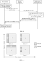
- the first indication is transmitted on a sidelink control channel (physical sidelink control channel, PSCCH), and the first data is transmitted on a physical sidelink shared channel (physical sidelink shared channel, PSSCH); and a time domain resource occupied by the PSCCH is different from a time domain resource occupied by the PSSCH, or a frequency domain resource occupied by the PSCCH is different from a frequency domain resource occupied by the PSSCH, or a frequency domain resource occupied by the PSCCH is different from a frequency domain resource occupied by the PSSCH and a time domain resource occupied by the PSCCH is different from a frequency domain resource occupied by the PSSCH.
- PSSCH physical sidelink shared channel
- the PSSCH and the PSCCH may be multiplexed together and sent to the second terminal.
- the PSSCH and the PSCCH may be sent by using four frame structures shown in FIG. 4-1 .
- the four frame structures are respectively:
- Option 1a The PSCCH and the PSSCH are in same frequency domain and do not overlap in time domain.
- Option 1b The PSCCH and the PSSCH overlap in frequency domain but do not overlap in time domain.
- Option 2 The PSCCH and the PSSCH are in same time domain and do not overlap in frequency domain.
- Option 3 A part of the PSCCH and a part of the PSSCH are in same time domain and do not overlap in frequency domain, and a remaining part of the PSCCH and a remaining part of the PSSCH overlap in frequency domain but do not overlap in time domain.
- Step 403 The second terminal receives the first indication and the first data that are sent by the first terminal through the first path, and sends second data according to the first indication.
- the second terminal may process the first data received from the first path, by using a PHY layer, a MAC layer, an RLC layer, and a PDCP layer that are in the second terminal and that are corresponding to the first terminal, to obtain the identifier of the first terminal, the first indication, and the first RRC message, and send the second data according to the first indication.
- the first indication is processed by using a protocol layer newly added to the first terminal and is included in the first data
- a protocol layer is also newly added to the second terminal, and the first data is processed by using the protocol layer, to obtain the first indication.
- the second terminal receives, from the first path, the first data sent by the first terminal, processes the received first data by using the PHY layer, the MAC layer, the RLC layer, and the PDCP layer that are in the second terminal and that are corresponding to the first terminal, to obtain the identifier of the first terminal and the first RRC message, and sends the second data according to the first indication in the SCI.
- FIG. 2 shows a PHY layer 1, a MAC layer 1, an RLC layer 1, and a PDCP layer 1 that are in the second terminal and that are end-to-end connected to the PHY layer, the MAC layer, the RLC layer, and the PDCP layer of the first terminal.
- the MAC layer, the RLC layer, and the PDCP layer that are in the second terminal and that are corresponding to the first terminal refer to the prior art. Details are not described.
- the second data may include the identifier of the first terminal and the first RRC message.
- the second data may include a data packet header and a payload (payload), the first RRC message may be included in the payload of the second data, and the identifier of the first terminal may be included in the data packet header of the second data.
- the second data may include the first RRC message, and the first RRC message may include the identifier of the first terminal.
- that the second terminal sends the second data may include the following two cases:
- the second path is a wireless communications interface between the second terminal and the radio access network device, and the second path may be an LTE-standard air interface (LTE air interface for short) such as a Uu interface, or an NR-standard air interface (NR air interface for short) such as an Nu interface.
- LTE air interface for short LTE-standard air interface
- NR air interface for short NR air interface for short
- the second terminal may send the second data to another relay device (for example, the third terminal) through a direct connection path between the second terminal and the another relay device, and the another relay device sends the first RRC message to the radio access network device.
- another relay device for example, the third terminal
- the another relay device sends the first RRC message to the radio access network device.
- Case 2 A second path is established between the second terminal and the radio access network device.
- the second terminal may send the second data to the radio access network device through the second path.
- the details of the second terminal sending the second data are not covered by the appended claims.
- the second data may include the first RRC message, and may further include the identifier of the first terminal.
- the first RRC message includes the identifier of the first terminal.
- the second terminal needs to include an RRC message indication or an RRC connection request indication (or an SRB 0 indication) in the second data.
- the RRC message indication or the RRC connection request indication (or the SRB 0 indication) is used to indicate that data received by the radio access network device from the second path is an RRC message, an RRC connection request message, or an RRC message corresponding to an SRB 0.
- the radio access network device may determine, based on the RRC message indication or the RRC connection request indication (or the SRB 0 indication), that the received data is an RRC message, then obtain the identifier of the first terminal by reading the first RRC message, and determine, based on the identifier of the first terminal, that the RRC message is the RRC message sent by the first terminal.
- the implementation is as follows:
- the second terminal sends the second data to the radio access network device through a data radio bearer (data radio barrier, DRB) between the second terminal and the radio access network device.
- a data radio bearer data radio barrier, DRB
- the second terminal may send the second data to the radio access network device through the data radio bearer (data radio barrier, DRB) between the second terminal and the radio access network device.
- the PDCP layer, the RLC layer, the MAC layer, and the PHY layer that are in the second terminal and that are corresponding to the radio access network device may be shown in FIG. 2.
- FIG. 2 shows a PHY layer 2, a MAC layer 2, an RLC layer 2, and a PDCP layer 2 that are in the second terminal and that are end-to-end connected to a PHY layer, a MAC layer, an RLC layer, and a PDCP layer of the radio access network device.
- the first RRC message included in the second data remains unchanged after the second data is processed by using different protocol layers of the second terminal, but information included in a data packet header may be different after the data packet header of the second data is processed by using different protocol layers.
- the data packet header may include a PDCP sequence number.
- the data packet header may further include an LCID and the like in addition to the PDCP sequence number.
- the identifier of the first terminal may be included in the second data when the second data is processed by using the PDCP layer, or may be included in the second data when the second data is processed by using the RLC layer, or may be included in the second data when the second data is processed by using the MAC layer.
- a new protocol layer (for example, adaptation) corresponding to the radio access network device may be further added to the second terminal.
- the newly added protocol layer is mainly responsible for encapsulating the identifier of the first terminal into the second data, that is, the identifier of the first terminal may be included in the second data when the second data is processed by using the newly added protocol layer.
- the newly added protocol layer in the second terminal may be deployed above the PDCP layer of the second terminal, or deployed between the PDCP layer and the RLC layer, or deployed between the RLC layer and the MAC layer.
- the second data may further include a newly added protocol layer indication
- the newly added protocol layer indication may be included in the second data when the second data is processed by using the PDCP layer, the RLC layer, the MAC layer, or the PHY layer, so that the radio access network device determines, according to the newly added protocol layer indication, to deliver the received second data to the newly added protocol layer of the radio access network device for processing.
- the newly added protocol layer of the radio access network device is mainly responsible for decapsulating the second data to obtain the identifier of the first terminal, and learning, based on the identifier of the first terminal, that the first RRC message received from the second terminal is the RRC message sent by the first terminal.
- the second data may include the first RRC message, and may further include the identifier of the first terminal.
- the second data may include the first RRC message, and the first RRC message includes an identifier of the first terminal.
- the second data may further include an RRC message indication, and the RRC message indication may be used to indicate that a message included in the second data is an RRC message.
- the radio access network device delivers, according to the RRC message indication, the first RRC message in the second data to the RRC layer of the radio access network device for processing.
- the RRC message indication may be included in the second data when the second data is processed by using the PDCP layer.
- the RRC message indication may be included in the second data when the second data is processed by using the RLC layer.
- the RRC message indication may be included in the second data when the second data is processed by using the MAC layer.
- the RRC message indication may be included in the second data when the second data is processed by using the newly added protocol layer. This is not limited. For example, for related descriptions of the newly added protocol layer, refer to the foregoing descriptions. Details are not described again.
- the radio access network device may determine, based on the identifier of the first terminal, that the second data includes the first RRC message of the first terminal, so as to deliver the first RRC message in the second data to the RRC layer of the radio access network device for processing.
- the RRC message indication may also be included.
- the second terminal after processing the second data by using a PDCP layer, an RLC layer, a MAC layer, and a PHY layer that are in the second terminal and that are corresponding to the radio access network device, the second terminal sends the second data to the radio access network device through a signaling radio bearer (signal radio barrier, SRB) 1 between the second terminal and the radio access network device.
- a signaling radio bearer signal radio barrier, SRB
- the second data may include the first RRC message, and the first RRC message includes the identifier of the first terminal.
- the second data may further include an RRC connection request indication (or an SRB 0 indication), so that after receiving the second data, the radio access network device directly sends, according to the RRC connection request indication (or the SRB 0 indication), the first RRC message to the RRC layer of the radio access network device for processing.
- the RRC connection request indication may indicate the radio access network device to establish an RRC connection to the first terminal, that is, indicate that the message is an RRC message.
- the SRB 0 indication may be used to indicate that the first RRC message is an RRC message carried on an SRB 0.
- the radio access network device may determine, based on the identifier of the first terminal, that the second data includes the first RRC message of the first terminal, so as to deliver the first RRC message in the second data to the RRC layer of the radio access network device for processing.
- the RRC message indication may also be included.
- the second terminal after processing the second data by using a PDCP layer, an RLC layer, a MAC layer, and a PHY layer that are in the second terminal and that are corresponding to the radio access network device, the second terminal sends the second data to the radio access network device through a signaling radio bearer (signal radio barrier, SRB) 1 between the second terminal and the radio access network device.
- SRB signaling radio barrier
- Step 404 The radio access network device receives the second data sent by the second terminal, and generates a second RRC message corresponding to the first RRC message.
- the second RRC message may be used to indicate whether the RRC connection between the first terminal and the radio access network device is successfully established.
- the second RRC message is used to indicate that the RRC connection between the first terminal and the radio access network device is successfully established.
- the second RRC message may be RRC connection setup (RRC Connection Setup or RRC setup), RRC connection reestablishment (RRC connection reestablishment or RRC reestablishment), or RRC connection resume (RRC connection resume or RRC resume).
- the second RRC message may include an identifier of the second logical channel of the first path, and may further include a cell radio network temporary identifier (cell radio network temporary identifier, C-RNTI) configured by the radio access network device for the first terminal, a configuration of the SRB 1 between the radio access network device and the first terminal, and other information.
- the second logical channel is a logical channel used to transmit, an RRC message sent by the first terminal to the radio access network device and an RRC message sent by the radio access network device to the first terminal, between the first terminal and the second terminal after the RRC connection is established between the first terminal and the radio access network device.
- an RRC message subsequently sent by the second terminal to the first terminal by using the LCID 1 may be an RRC message sent by the radio access network device
- an RRC message sent by the first terminal to the second terminal by using the LCID 1 may be an RRC message sent to the radio access network device.
- the second RRC message may not include the configuration of the SRB 1 between the radio access network device and the first terminal.
- the first terminal may establish an RRC connection to the radio access network device by using an original SRB 1 configuration between the radio access network device and the first terminal or a default SRB 1 configuration.
- the second RRC message may further include the cell identifier of the serving cell of the first terminal.
- the radio access network device may process the received second data by using the MAC layer, the RLC layer, and the PDCP layer of the radio access network device, to obtain the identifier of the first terminal and the first RRC message, determine, based on the identifier of the first terminal, that the received first RRC message is an RRC message sent by the first terminal, and send the first RRC message to the RRC layer of the radio access network device for processing, to obtain the second RRC message.
- the radio access network device may process the received second data by using the MAC layer, the RLC layer, and the PDCP layer of the radio access network device, to obtain the identifier of the first terminal and the first RRC message, determine, based on the identifier of the first terminal, that the received first RRC message is an RRC message sent by the first terminal, and send the first RRC message to the RRC layer of the radio access network device for processing, to obtain the second RRC message.
- the first RRC message is sent to the RRC layer of the radio access network device for processing, to
- the radio access network device may process the received second data by using the MAC layer, the RLC layer, and the PDCP layer of the radio access network device, to obtain the RRC message indication, the identifier of the first terminal, and the first RRC message, determine, according to the RRC message indication, that a message received from the second terminal is an RRC message, determine, based on the identifier of the first terminal, that the RRC message is an RRC message sent by the first terminal, and send the first RRC message to the RRC layer of the radio access network device for processing, to obtain the second RRC message.
- the radio access network device receives, through the DRB, the second data that is sent by the second terminal and that includes the RRC message indication and the first RRC message, and the radio access network device learns, according to the RRC message indication or the RRC connection request indication (or the SRB 0 indication) in the second data, that the second data includes the first RRC message. Then, the radio access network device obtains the identifier of the first terminal by reading the first RRC message, and determines that the RRC message is the RRC message sent by the first terminal.
- the radio access network device may process the received second data by using the MAC layer, the RLC layer, and the PDCP layer of the radio access network device, to parse out a message type of the first RRC message, determine, based on the message type of the first RRC message, that the received message is an RRC message corresponding to an SRB 0, determine, based on the identifier of the first terminal, that the RRC message is an RRC message sent by the first terminal, and send the first RRC message to the RRC layer for processing, to obtain the second RRC message.
- the second data further includes an RRC message indication or an RRC connection request indication (or an SRB 0 indication).
- the radio access network device processes the received second data by using the MAC layer, the RLC layer, and the PDCP layer of the radio access network device, to obtain the RRC message indication or the RRC connection request indication (or the SRB 0 indication), the identifier of the first terminal, and the first RRC message, determines, based on the RRC message indication or the RRC connection request indication (or the SRB 0 indication) and the identifier of the first terminal, that the received message is an RRC message, and directly sends the second data to the RRC layer for processing, to obtain the second RRC message.
- the radio access network device may receive the first RRC message that is sent by the remote device and that is used to request to establish an RRC connection, and generate, based on the received first RRC message, the second RRC message used to establish the RRC connection between the remote device and the radio network device.
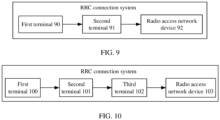
- the radio access network device may further send the second RRC message to a first device through the second terminal, so that an RRC connection is established between the first device and the radio access network device.
- the process is shown in FIG. 4 , and may include the following steps.
- Step 405 The radio access network device sends the identifier of the first terminal and the second RRC message to the second terminal through the second path.
- the radio access network device may include the identifier of the first terminal and the second RRC message to third data, and send the third data to the second terminal through the second path.
- the third data may include a data packet header and a payload (payload)
- the second RRC message may be included in the payload of the third data
- the identifier of the first terminal may be included in the data packet header of the third data.
- the radio access network device may process the third data by using a PDCP layer, an RLC layer, a MAC layer, and a PHY layer that are in the radio access network device and that are corresponding to the second terminal, and then send the third data to the second terminal through a data radio bearer DRB between the second terminal and the radio access network device.
- a PDCP layer, the RLC layer, the MAC layer, and the PHY layer that are in the radio access network device and that are corresponding to the second terminal may be shown in FIG. 2.
- FIG. 2 shows the PDCP layer, the RLC layer, the MAC layer, and the PHY layer that are in the radio access network device and that are end-to-end connected to a PDCP layer 2, an RLC layer 2, a MAC layer 2, and a PHY layer 2 of the second terminal.
- the radio access network device after processing the third data by using a PDCP layer, an RLC layer, a MAC layer, and a PHY layer that are in the radio access network device and that are corresponding to the second terminal, the radio access network device sends the third data to the second terminal through an SRB 1 between the radio access network device and the second terminal.
- the second RRC message included in the third data after the third data is processed by different protocol layers of the radio access network device remains unchanged, but information included in a data packet header of the third data after the third data is processed by different protocol layers may be different.
- the data packet header may include the identifier of the first terminal.
- the data packet header may further include a PDCP sequence number.
- the data packet header may further include an LCID in addition to the identifier of the first terminal and the PDCP sequence number, so that the second terminal device forwards the second RRC message to the first terminal on the first path.
- the identifier of the first terminal may be further included in a newly added adaptation layer packet header.
- the radio access network device may further include, to the third data, an indication used to indicate the second terminal to send the second RRC message to the first terminal.
- the indication may be included in the newly added adaptation layer packet header or an existing PDCP/RLC/MAC/PHY layer packet header.
- Step 406 The second terminal receives the third data that includes the identifier of the first terminal and the second RRC message, and sends the second RRC message to the first terminal through the first path based on the identifier of the first terminal.
- the second terminal may process the received third data by using the PHY layer 2, the MAC layer 2, the RLC layer 2, and the PDCP layer 2 of the second terminal, to obtain the identifier of the first terminal and the second RRC message, determine, based on the identifier of the first terminal, that the received second RRC message is an RRC message sent by the radio access network device to the first terminal, and send the second RRC message to the first terminal through the first path.
- the third data includes the indication used to indicate the second terminal to send the second RRC message to the first terminal.
- the second terminal sends the second RRC message to the first terminal through the first path according to the indication.
- the indication may be included in the newly added adaptation layer packet header or an existing PDCP/RLC/MAC/PHY layer packet header.
- that the second terminal sends the second RRC message to the first terminal through the first path may include: The second terminal includes the received second RRC message to a payload of data, processes the data by using the PDCP layer 1, the RLC layer 1, the MAC layer 1, and the PHY layer 1 of the second terminal, and sends the data to the first terminal through the first path.
- Step 407 The first terminal receives the second RRC message that is sent by the second terminal through the first path.
- the first terminal processes the received data by using the PHY layer, the MAC layer, the RLC layer, and the PDCP layer of the first terminal, to obtain the second RRC message.
- the first terminal may configure the SRB 1 between the first terminal and the radio access network device based on the second RRC message.
- the first terminal may configure the SRB 1 based on a previously stored SRB 1 configuration or a default SRB 1 configuration.
- mapping relationship between the SRB 1 between the first terminal and the radio access network device and the identifier of the second logical channel, so that after subsequently receiving the data through the second logical channel, the first terminal determines, based on the mapping relationship, that the received data is an RRC message sent by the radio access network device, and sends the received RRC message to the PDCP layer that is in the first terminal and that is corresponding to the SRB 1 for processing.
- the first terminal configures the SRB 1 between the first terminal and the radio access network device based on the second RRC message, refer to the prior art. Details are not described again.
- the third data may further include the identifier of the second logical channel; or the method further includes: sending, by the radio access network device, a fourth RRC message to the second terminal.
- the fourth RRC message may be sent when the radio access network device sends the third data, or may be sent before or after the radio access network device sends the third data.
- the fourth RRC message may include the identifier of the second logical channel, and the radio access network device may send the fourth RRC message to the second terminal through the SRB 1 between the second terminal and the radio access network device.
- the second terminal may determine, based on the identifier of the second logical channel, to send the received RRC message sent by the radio access network device to the first terminal, to the first terminal through the second logical channel.
- the first terminal After receiving the RRC message from the second logical channel, the first terminal uploads the data to a PDCP layer that is in the first terminal and that is corresponding to the SRB 1 for processing.
- the radio access network device sends a third RRC message to the second terminal.
- the third RRC message may be a signaling message, for example, an RRC reconfiguration message, sent by the radio access network device to the first terminal after the first terminal establishes an RRC connection to the radio access network device.
- the radio access network device may further send the identifier of the first terminal to the second terminal while sending the third RRC message to the second terminal.
- the second terminal receives the third RRC message, and sends the third RRC message to the first terminal through the second logical channel.
- the first terminal receives the third RRC message that is sent by the second terminal through the second logical channel, and sends, based on the mapping relationship between the identifier of the second logical channel and the SRB 1 between the first terminal and the radio access network device, the third RRC message to the PDCP layer corresponding to the SRB 1 between the first terminal and the radio access network device for processing.
- the method may further include: sending, by the radio access network device, an indication message to the first terminal through the second terminal.
- the indication message may be used to indicate that the third RRC message is from the radio access network device.
- the indication message may be included in the third data that carries the third RRC message.
- the indication message may be included in a newly added adaptation layer/PDCP/RLC/MAC PDU, to be specific, the indication message is included in the third data, for example, included in a newly added adaptation layer PDCP/RLC/MAC header, when the third data is processed by using the newly added adaptation layer/PDCP/RLC/MAC layer.
- a specific location of the newly added adaptation layer is not limited in this specification.
- the indication message may be a binary bit number 0 or 1 or another symbol. Specifically, which symbol is used to represent the first indication may be specified in a protocol in advance. This is not limited in this embodiment of this application. For example, the bit number "1" is used to indicate that the third RRC message is from the radio access network device.
- the second terminal may include the bit number "1" to the MAC header of the first data, and send the subsequent processed first data to the first terminal.
- the first terminal receives the indication message sent by the second terminal, determines, based on the indication message, that the third RRC message received on the second logical channel is an RRC message from the radio access network device, and sends the third RRC message to the PDCP layer corresponding to the SRB 1 between the first terminal and the radio access network device for processing.
- Manner 1 Before the first terminal sends the first indication and the first data to the second terminal through the first path, the first terminal receives a discovery message (for example, a discovery request or a discovery response) sent by one or more terminals, and determines, based on the discovery message, that the first RRC message is to be sent by the second terminal to the radio access network device.
- a discovery message for example, a discovery request or a discovery response
- the one or more terminals may include the second terminal, and the discovery message sent by each terminal includes any one or more pieces of information of: a cell identifier of a serving cell of the terminal, a time advance (timing advance, TA) from the terminal to the radio access network device, a hop count from the terminal to the radio access network device, a group identifier of a group in which the terminal is located, quality of a transmission link between the terminal and the radio access network device, and quality of a transmission link between the terminal and the first terminal.
- TA timing advance
- the cell identifier of the serving cell of the terminal may be a cell identifier of a cell serving the terminal.
- the cell identifier may be an ECGI, an NR CGI, or a PCI, and the cell identifier may be used to identify the serving cell of the terminal.
- the TA from the terminal to the radio access network device may be a time advance of sending uplink data by the terminal to the radio access network device relative to receiving data from the radio access network device.
- a shorter distance to the radio access network device indicates a smaller TA from the terminal to the radio access network device.
- a longer distance to the radio access network device indicates a larger TA from the terminal to the radio access network device.
- the hop count from the terminal to the radio access network device may be a quantity of relay devices through which the terminal sends data to the radio access network device. For example, if a terminal 1 sends data to the radio access network device through a terminal 2, a terminal 3, and a terminal 4, the hop count from the terminal 1 to the radio access network device is 3. A shorter distance between the terminal and the radio access network device indicates a smaller hop count from the terminal to the radio access network device. On the contrary, a longer distance between the terminal and the radio access network device indicates a larger hop count from the terminal to the radio access network device.
- the identifier of the group in which the terminal is located may be used to identify a group to which the terminal belongs. For example, the first terminal may select the second terminal in a same group as the first terminal as a relay to forward the first RRC message.
- the quality of the transmission link between the terminal and the radio access network device may include reference signal receiving power (reference signal receiving power, RSRP) or reference signal receiving quality (reference signal receiving quality, RSRQ) between the terminal and the radio access network device.
- RSRP reference signal receiving power
- RSRQ reference signal receiving quality
- Larger RSRP or RSRQ between the terminal and the radio access network device indicates better quality of the transmission link between the terminal and the radio access network device.
- smaller RSRP or RSRQ between the terminal and the radio access network device indicates poorer quality of the transmission link between the terminal and the radio access network device.
- the quality of the transmission link between the terminal and the first terminal may include RSRP or RSRQ between the terminal and the first terminal. Larger RSRP or RSRQ between the terminal and the first terminal indicates better quality of the transmission link between the terminal and the first terminal. On the contrary, smaller RSRP or RSRQ between the terminal and the first terminal indicates poorer quality of the transmission link between the terminal and the first terminal.
- the second terminal is any one of the one or more terminals. That the first terminal determines, based on the discovery message, that the first RRC message is to be sent by the terminal to the radio access network device may include the following steps:
- the first terminal searches for cell identifiers of serving cells, compares the cell identifiers of the found serving cells with cell identifiers of serving cells of the one or more terminals, and selects, from the one or more terminals, a terminal whose serving cell has a cell identifier the same as the cell identifier of the serving cell of the first terminal, to send the first RRC message to the radio access network device.
- a process in which the first terminal searches for the cell identifier of the serving cell refer to the prior art. Details are not described again.
- the first terminal sorts TAs from the one or more terminals to the radio access network device, and selects one or more terminals with smaller TAs from the one or more terminals, to send the first RRC message to the radio access network device.
- the first terminal sorts hop counts from the one or more terminals to the radio access network device, and selects one or more terminals with relatively small TAs from the one or more terminals, to send the first RRC message to the radio access network device.
- the first terminal compares the identifier of the group in which the first terminal is located with an identifier of a group in which the one or more terminals are located, and selects, from the one or more terminals, a terminal in a group whose identifier is the same as the identifier of the group in which the first terminal is located, to send the first RRC message to the radio access network device.
- the first terminal sorts quality of transmission links between the one or more terminals and the radio access network device, and selects one or more terminals with relatively high transmission link quality from the one or more terminals, to send the first RRC message to the radio access network device.
- the first terminal sorts quality of transmission links between the one or more terminals and the first terminal, and selects one or more terminals with relatively high transmission link quality from the one or more terminals, to send the first RRC message to the radio access network device.
- the first terminal compares the cell identifier of the found serving cell (or an identifier of a group in which the found serving cell is located) with a cell identifier of a serving cell of the one or more terminals (or an identifier of a group in which the serving cell of the one or more terminals is located), obtains, from the one or more terminals, terminals in a serving cell whose cell identifier (or whose identifier of a group in which the serving cell of the terminals is located) is the same as the cell identifier of the found serving cell (or the identifier of the group in which the found serving cell is located), sorts TAs (and/or hop counts) between the terminals and the radio access network device, and selects one or more terminals with smaller TAs (and/or hop counts), to send the first RRC message to the radio access network device.
- the first terminal compares the cell identifier of the found serving cell (or an identifier of a group in which the found serving cell is located) with a cell identifier of a serving cell of the one or more terminals (or an identifier of a group in which the serving cell of the one or more terminals is located), obtains, from the one or more terminals, terminals in a serving cell whose cell identifier (or whose identifier of a group in which the serving cell of the terminals is located) is the same as the cell identifier of the found serving cell (or the identifier of the group in which the found serving cell is located), sorts quality of transmission links between the terminals and the radio access network device (and/or quality of transmission links between the terminals and the first terminal), and selects one or more terminals with relatively high transmission link quality, to send the first RRC message to the radio access network device.
- the first terminal compares the cell identifier of the found serving cell (or an identifier of a group in which the found serving cell is located) with a cell identifier of a serving cell of the one or more terminals (or an identifier of a group in which the serving cell of the one or more terminals is located), obtains, from the one or more terminals, terminals in a serving cell whose cell identifier (or whose identifier of a group in which the serving cell of the terminals is located) is the same as the cell identifier of the found serving cell (or the identifier of the group in which the found serving cell is located), sorts TAs (and/or hop counts) between the terminals and the radio access network device and sorts quality of transmission links between the terminals and the radio access network device (and/or quality of transmission links between the terminals and the first terminal), and selects one or more terminals with smaller TAs (and/or hop counts) and relatively high transmission link quality, to send the first RRC message to the radio access network device.
- the first data may further include the identifier of the second terminal or the identifier of the group in which the second terminal is located.
- the identifier of the second terminal or the identifier of the group in which the second terminal is located may be included in a destination address segment of a data packet header when the first data is processed by using the MAC layer of the first terminal.
- the first data may further include any one or more pieces of information of a preset TA threshold from the terminal to the radio access network device and a preset hop count threshold from the terminal to the radio access network device.
- the second terminal may determine, based on the any one or more pieces of information of the TA threshold and the hop count threshold, whether to send the first RRC message in the first data. If the second terminal determines to send the first RRC message in the first data, step 303 is performed; otherwise, step 303 is not performed, and a forwarding failure indication is sent to the first terminal.
- the forwarding failure indication may be used to indicate that the second terminal has not sent the first RRC message to the radio access network device.
- the second terminal when determining to forward the first RRC message in the first data, performs step 303 of sending a forwarding success indication to the first terminal.
- the forwarding success indication may be used to indicate that the second terminal has sent the first RRC message to the radio access network device.
- the second terminal sends a forwarding indication to the first terminal.
- the forwarding indication is used to indicate whether the second terminal has sent the first RRC message to the radio access network device.
- the TA threshold is used to limit a maximum TA for sending uplink data by the terminal to the radio access network device. If the TA from the terminal to the radio access network device is greater than the TA threshold, it indicates that the terminal is relatively far away from the radio access network device, and is not suitable to send the first RRC message to the radio access network device; otherwise, it may be determined that the first RRC message is to be sent by the terminal to the radio access network device.
- the hop count threshold is used to limit a maximum hop count from the terminal to the radio access network device. If the hop count from the terminal to the radio access network device is greater than the hop count threshold, it indicates that the terminal is relatively far away from the radio access network device, and is not suitable to send the first RRC message to the radio access network device; otherwise, it may be determined that the first RRC message is to be sent by the terminal to the radio access network device.
- the second terminal determines, based on the any one or more pieces of information of the TA threshold and the hop count threshold, whether to send the first RRC message in the first data may include:
- the first terminal may send the first RRC message to the radio access network device through the second terminal.
- the radio access network device After receiving the first RRC message, the radio access network device generates the second RRC message, and sends the second RRC message to the first terminal through the second terminal, so that the first terminal establishes an RRC connection between the first terminal and the radio access network device based on the received second RRC message.
- FIG. 4 is described by using an example in which a wireless communications interface is established between the second terminal and the radio access network device.
- the second terminal may send the first RRC message to the radio access network device through another relay device that establishes a wireless communications interface with the radio access network device, wherein the details of the second terminal sending the first RRC message are not covered by the appended claims.
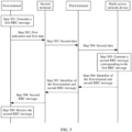
- the method is shown in FIG. 5 , and may include the following steps.
- Step 501 A first terminal generates a first RRC message.
- Step 501 is the same as step 401. Details are not described again.
- Step 502 The first terminal sends a first indication and first data to a second terminal through the first path.
- Step 502 is the same as step 402. Details are not described again.
- Step 503 The second terminal receives the first indication and the first data that are sent by the first terminal through the first path, and sends second data to a third terminal according to the first indication.
- the third terminal may be any terminal that establishes a wireless communications interface with the second terminal. Specifically, it may be determined, in the foregoing Manner 1 or Manner 2, that the first RRC message is to be sent by the third terminal to the radio access network device.
- the second data may further include a second indication.
- the second indication may be used to indicate the third terminal to send the first RRC message to the radio access network device.
- the second indication may be a preset identifier of a logical channel between the second terminal and the third terminal, or may be an indication in a newly added adaptation layer PDU, a PDCP PDU, an RLC PDU, or a MAC PDU of the second terminal, or may be an indication included in SCI that is sent by the second terminal to the third terminal. Details are not described again.
- Step 504 The third terminal receives the second indication and the second data that are sent by the second terminal, and sends the second data to the radio access network device according to the second indication.
- a radio interface channel namely, a second channel
- a process in which the third terminal sends the second data to the radio access network device is the same as the process in which the second terminal sends the second data to the radio access network device in the method shown in FIG. 4 . Details are not described again.
- the second data sent by the third terminal to the radio access network device may include an identifier of the second terminal, for example, an identifier of the second terminal on a PC5 interface or a sidelink sidelink, so that when subsequently sending a second RRC message, the radio access network device sends the second RRC message to the first terminal through the second terminal.
- Step 505 The radio access network device receives the second data sent by the third terminal, and generates the second RRC message corresponding to the first RRC message.
- step 505 refer to the description of step 504. Details are not described again.
- the radio access network device may receive, through the second terminal and the third terminal, the first RRC message that is sent by the first terminal and that is used to request to establish an RRC connection, and generate, based on the received first RRC message, the second RRC message used to establish the RRC connection between the remote device (that is, the first terminal) and the radio network device.
- the method may further include the following steps.
- Step 506 The radio access network device sends the identifier of the first terminal and the second RRC message to the third terminal.
- the identifier of the first terminal and the second RRC message may be included in third data.
- the third data is shown in FIG. 4 .
- the radio access network device sends the third data to the third terminal refer to the manner in which the radio access network device sends the third data to the second terminal in FIG. 4 . Details are not described again.
- the radio access network device may further send the identifier of the second terminal to the third terminal while sending the identifier of the first terminal and the second RRC message to the third terminal.
- the identifier of the second terminal may be included in the third data that is sent by the radio access network device to the third terminal.
- the identifier of the first terminal may be an identifier of the first terminal on the PC5 interface or the sidelink sidelink
- the identifier of the second terminal may be an identifier of the second terminal on the PC5 interface or the sidelink sidelink.
- Step 507 The third terminal receives the identifier of the first terminal and the second RRC message, and sends an indication of the first terminal and the second RRC message to the second terminal.
- Step 508 The second terminal receives the indication of the first terminal and the second RRC message, and sends the second RRC message to the first terminal according to the indication of the first terminal.
- Step 509 The first terminal receives the second RRC message sent by the second terminal.
- the first terminal may configure an SRB 1 between the first terminal and the radio access network device based on the second RRC message.
- the first terminal may configure the SRB 1 based on a previously stored SRB 1 configuration or a default SRB 1 configuration.
- the third data may further include the identifier of the second logical channel; or the method further includes: sending, by the radio access network device, a fourth RRC message to the second terminal through the third terminal.
- the fourth RRC message may be sent when the radio access network device sends the third data, or may be sent before or after the radio access network device sends the third data.
- the fourth RRC message may include the identifier of the second logical channel.
- the second terminal may determine, based on the identifier of the second logical channel, to send the received RRC message sent by the radio access network device to the first terminal, to the first terminal through the second logical channel.
- the first terminal After receiving the RRC message from the second logical channel, the first terminal uploads the RRC message to the PDCP layer corresponding to the SRB 1 for processing.
- the radio access network device sends a third RRC message to the second terminal through the third terminal.
- the second terminal receives the third RRC message, and sends the third RRC message to the first terminal through the second logical channel.
- the first terminal receives the third RRC message that is sent by the second terminal through the second logical channel, and sends, based on the mapping relationship between the identifier of the second logical channel and the SRB 1 between the first terminal and the radio access network device, the third RRC message to the PDCP layer corresponding to the SRB 1 between the first terminal and the radio access network device for processing.
- the third RRC message is described above. Details are not described again.
- the method may further include: sending, by the radio access network device, an indication message to the first terminal through the third terminal and the second terminal.
- the indication message may be used to indicate that the third RRC message is from the radio access network device.
- the first terminal receives the indication message, determines, based on the indication message, that the third RRC message received on the second logical channel is an RRC message from the radio access network device, and sends the third RRC message to the PDCP layer corresponding to the SRB 1 between the first terminal and the radio access network device for processing.
- the indication message may be carried in a data packet header when the third terminal or the second terminal sends the third RRC message on the PC5 interface or the sidelink.
- the second terminal sends the first RRC message to the radio access network device through only one relay device.
- the second terminal may alternatively send the first RRC message to the radio access network device through a plurality of hops, for example, through a plurality of relay devices such as the third terminal and a fourth terminal.
- the second terminal sends the first RRC message to the radio access network device through a plurality of hops for a process of forwarding the first RRC message between the plurality of hops, refer to the process in which the second terminal sends the first RRC message to the third terminal. Details are not described again.
- the first terminal may send the first RRC message to the radio access network device through the second terminal and the third terminal.
- the radio access network device After receiving the first RRC message, the radio access network device generates the second RRC message, and sends the second RRC message to the first terminal through the third terminal and the second terminal, so that the first terminal establishes an RRC connection between the first terminal and the radio access network device based on the received second RRC message.
- the first terminal, the second terminal, and the radio access network device include corresponding hardware structures and/or software modules for performing the functions.
- a person skilled in the art should be easily aware that, in combination with the examples of units and algorithm steps described in the embodiments disclosed in this specification, this application can be implemented by hardware or a combination of hardware and computer software. Whether a function is performed by hardware or hardware driven by computer software depends on particular applications and design constraints of the technical solutions. A person skilled in the art may use different methods to implement the described functions for each particular application, but it should not be considered that the implementation goes beyond the scope of this application.
- the first terminal, the second terminal, and the radio access network device may be divided into functional modules based on the foregoing method examples.
- each functional module may be obtained through division based on each corresponding function, or two or more functions may be integrated into one processing module.
- the integrated module may be implemented in a form of hardware, or may be implemented in a form of a software functional module.
- module division is used as an example, and is merely logical function division. In actual implementation, another division manner may be used.
- FIG. 6 is a schematic composition diagram of a communications apparatus.
- the communications apparatus is according to the invention a first terminal, or may be, in examples not covered by the claimed invention, a chip or a system-on-a-chip in the first terminal.
- the communications apparatus is configured to perform a function of the first terminal in the foregoing embodiments.
- the communications apparatus shown in FIG. 6 includes a generation unit 60 and a sending unit 61.
- the generation unit 60 is configured to generate a first RRC message.
- the generation unit 60 may be configured to support the communications apparatus in performing step 401 and step 501.
- the sending unit 61 is configured to send a first indication and first data to a second terminal through a wireless communications interface between the first terminal and the second terminal, where the first indication is used to indicate the second terminal to send the first RRC message to a radio access network device.
- the sending unit 61 may be configured to support the communications apparatus in performing step 402 and step 502.
- the communications apparatus may further include: a receiving unit 62, configured to receive a second RRC message that is sent by the second terminal through the first path and that includes an identifier of a second logical channel of the first path.
- the receiving unit 62 may be configured to support the communications apparatus in performing step 406 and step 508.
- the second RRC message is from the radio access network device, there is a mapping relationship between the identifier of the second logical channel and an SRB 1 of the first terminal, and the SRB 1 of the first terminal is a signaling radio bearer between the first terminal and the radio access network device.
- the receiving unit 62 is further configured to receive a third RRC message that is sent by the second terminal through the second logical channel.
- An RRC processing unit 63 is configured to send, based on the mapping relationship between the identifier of the second logical channel and the SRB 1, the third RRC message to a PDCP layer corresponding to the SRB 1 for processing.
- the communications apparatus configured to perform the function of the first terminal in the foregoing RRC connection methods, and therefore can achieve a same effect as the foregoing RRC connection methods.
- the communications apparatus shown in FIG. 6 may include a processing module and a communications module.
- the generation unit 60 and the RRC processing unit 63 are integrated into the processing module, and the sending unit 61 and the receiving unit 62 are integrated into the communications module.
- the processing module is configured to control and manage an action of the communications apparatus.
- the processing module is configured to support the communications apparatus in performing step 401, step 501, and another process of the technology described in this specification.
- the communications module is configured to support the communications apparatus in performing step 402, step 502, step 406, and step 508, and communicating with another network entity, for example, communicating with the relay device shown in FIG. 1 or the another network entity through a first path.
- the communications apparatus may further include a storage module, configured to store program code and data of the communications apparatus.
- the processing module may be a processor or a controller.
- the processor or the controller may implement or execute various example logical blocks, modules, and circuits described with reference to content disclosed in this application.
- the processor may be a combination of processors implementing a computing function, for example, a combination of one or more microprocessors, or a combination of a DSP and a microprocessor.
- the communications module may be a transceiver circuit, a communications interface, or the like.
- the storage module may be a memory.
- the processing module is a processor
- the communications module is a communications interface
- the storage module is a memory
- the communications apparatus shown in FIG. 6 may be the communications apparatus shown in FIG. 3 .
- FIG. 7 is a schematic composition diagram of a communications apparatus not covered by the claimed invention.
- the communications apparatus may be a second terminal, or a chip or a system-on-a-chip in the second terminal.
- the communications apparatus may be configured to perform a function of the second terminal in the foregoing embodiments.
- the communications apparatus shown in FIG. 7 includes a receiving unit 70 and a sending unit 71.
- the receiving unit 70 is configured to receive a first indication and first data that are sent by a first terminal through a first path, where the first data includes a first RRC message, and the first indication is used to indicate the second terminal to send the first RRC message to a radio access network device.
- the receiving unit 70 is configured to support the communications apparatus in performing the receiving action in step 403 and step 503.
- the sending unit 71 is configured to send second data according to the first indication.
- the second data includes an identifier of the first terminal and the first RRC message.
- the sending unit 71 is configured to support the communications apparatus in performing the sending action in step 403 and step 503.
- the receiving unit 70 is further configured to receive third data.
- the third data includes the identifier of the first terminal and a second RRC message, where the second RRC message includes an identifier of a second logical channel of the first path.
- the receiving unit 70 is further configured to support the communications apparatus in performing the receiving action in step 406 and step 508.
- the sending unit 71 is further configured to send the second RRC message to the first terminal through the first path based on the identifier of the first terminal.
- the sending unit 71 is further configured to support the communications apparatus in performing the sending action in step 406 and step 508.
- the communications apparatus configured to perform the function of the second terminal in the foregoing RRC connection methods, and therefore can achieve a same effect as the foregoing RRC connection methods.
- the communications apparatus shown in FIG. 7 may include a processing module and a communications module.
- the receiving unit 70 and the sending unit 71 may be integrated into the communications module.
- the processing module is configured to control and manage an action of the communications apparatus.
- the communications module is configured to support the communications apparatus in performing step 403, step 503, step 406, and step 508, and communicating with another network entity, for example, communicating with the remote device or the radio access network device shown in FIG. 1 , or the another network entity.
- the communications apparatus may further include a storage module, configured to store program code and data of the communications apparatus.
- the processing module may be a processor or a controller.
- the processor or the controller may implement or execute various example logical blocks, modules, and circuits described with reference to content disclosed in this application.
- the processor may be a combination of processors implementing a computing function, for example, a combination of one or more microprocessors, or a combination of a DSP and a microprocessor.
- the communications module may be a transceiver circuit, a communications interface, or the like.
- the storage module may be a memory.
- the processing module is a processor
- the communications module is a communications interface
- the storage module is a memory
- the communications apparatus shown in FIG. 7 may be the communications apparatus shown in FIG. 3 .
- FIG. 8 is a schematic composition diagram of a communications apparatus not covered by the claimed invention.
- the communications apparatus may be a radio access network device, or a chip or a system-on-a-chip in the radio access network device.
- the communications apparatus may be configured to perform a function of the radio access network device in the foregoing embodiments.
- the communications apparatus shown in FIG. 8 includes a receiving unit 80 and a generation unit 81.
- the receiving unit 80 is configured to receive, from a wireless communications interface between the radio access network device and a second terminal, second data sent by the second terminal, where the second data includes an identifier of a first terminal and a first RRC message.
- the receiving unit 80 may support the communications apparatus in performing the receiving action in step 404 and step 505.
- the generation unit 81 is configured to generate a second RRC message corresponding to the first RRC message.
- the generation unit 81 may be configured to support the communications apparatus in performing the action of generating the RRC message in step 404 and step 505.
- the communications apparatus may further include: a sending unit 82, configured to send the identifier of the first terminal and the second RRC message to the second terminal through the second path.
- the second RRC message includes an identifier of a second logical channel of a first path.
- the sending unit 82 may be configured to support the communications apparatus in performing step 405 and step 506.
- the communications apparatus configured to perform the function of the radio access network device in the foregoing RRC connection methods, and therefore can achieve a same effect as the foregoing RRC connection methods.
- the communications apparatus shown in FIG. 8 may include a processing module and a communications module.
- the processing module is integrated with a generation unit 81, and the communications module is integrated with a receiving unit 80 and a sending unit 82.
- the processing module is configured to control and manage an action of the communications apparatus.
- the processing module is configured to support the communications apparatus in performing the action of generating the RRC message in step 404 and step 505, and performing another process of the technology described in this specification.
- the communications module is configured to support the communications apparatus in performing the receiving action in step 404 and step 505, step 405 and step 506, and communicating with another network entity, for example, communicating with a functional module or a network entity shown in FIG. 1 .
- the communications apparatus may further include a storage module, configured to store program code and data of the communications apparatus.
- the processing module may be a processor or a controller.
- the processor or the controller may implement or execute various example logical blocks, modules, and circuits described with reference to content disclosed in this application.
- the processor may be a combination of processors implementing a computing function, for example, a combination of one or more microprocessors, or a combination of a DSP and a microprocessor.
- the communications module may be a transceiver circuit, a communications interface, or the like.
- the storage module may be a memory.
- the processing module is a processor
- the communications module is a communications interface
- the storage module is a memory
- the communications apparatus shown in FIG. 8 may be the communications apparatus shown in FIG. 3 .
- FIG. 9 is a schematic composition diagram of an RRC connection system, wherein an RRC connection system as such is not covered by the claimed invention.
- the RRC connection system may include a first terminal 90, a second terminal 91, and a radio access network device 92.
- a first path is established between the first terminal 90 and the second terminal 91, and the first terminal 90 and the second terminal 91 may communicate with each other through the first path.
- a second path is established between the second terminal 91 and the radio access network device 92, and the second terminal 91 and the radio access network device 92 may communicate with each other through the second path.
- the first terminal 90 has a function of the communications apparatus shown in FIG. 6 , and may be configured to: generate a first RRC message, send a first indication and first data to the second terminal 91 through a wireless communications interface between the first terminal 90 and the second terminal 91, and the first indication is used to indicate the second terminal 91 to send the first RRC message to the radio access network device 92.
- the second terminal 91 has a function of the communications apparatus shown in FIG. 7 , and may be configured to: receive a first indication and first data that are sent by the first terminal 90 through the first path, where the first data includes a first RRC message, and the first indication is used to indicate the second terminal 91 to send the first RRC message to the radio access network device 92; and send second data according to the first indication.
- the second data includes an identifier of the first terminal 90 and the first RRC message.
- the radio access network device 92 has a function of the communications apparatus shown in FIG. 8 , and may be configured to: receive, from a wireless communications interface between the radio access network device 92 and the second terminal 91, second data sent by the second terminal 91, where the second data includes an identifier of the first terminal 90 and a first RRC message, and generate a second RRC message corresponding to the first RRC message.
- the radio access network device 92 may be further configured to send the identifier of the first terminal 90 and the second RRC message to the second terminal 91 through the second path.
- the second RRC message includes an identifier of a second logical channel of a first path.
- the second terminal 91 may be further configured to receive third data.
- the third data includes the identifier of the first terminal 90 and a second RRC message, and the second RRC message includes an identifier of a second logical channel of the first path; and send the second RRC message to the first terminal 90 through the first path based on the identifier of the first terminal 90.
- the first terminal 90 may be further configured to receive the second RRC message that is sent by the second terminal 91 through the first path and that includes the identifier of the second logical channel of the first path.
- the second RRC message is from the radio access network device 92, there is a mapping relationship between the identifier of the second logical channel and an SRB 1 of the first terminal 90, and the SRB 1 of the first terminal 90 is a signaling radio bearer between the first terminal 90 and the radio access network device 92.
- the first terminal 90 may be further configured to: receive a third RRC message sent by the second terminal 91 through the second logical channel; and send, based on the mapping relationship between the identifier of the second logical channel and the SRB 1, the third RRC message to a PDCP layer corresponding to the SRB 1 for processing.
- the first terminal 90 may send an RRC message to the radio access network device 92 through the second terminal 91, so that the radio access network device 92 implements an RRC connection to the first terminal 90 based on the received RRC message.
- FIG. 10 is a schematic composition diagram of an RRC connection system, wherein the system as such is not covered by the claimed invention.
- the RRC connection system may include a first terminal 100, a second terminal 101, a third terminal 102, and a radio access network device 103.
- a first path is established between the first terminal 100 and the second terminal 101, and the first terminal 100 and the second terminal 101 may communicate with each other through the first path.
- a wireless communications interface is established between the second terminal 101 and the third terminal 102, a wireless communications interface is established between the third terminal 102 and the radio access network device 103, and the second terminal 101 and the radio access network device 103 may communicate with each other through the wireless communications interface.
- the first terminal 100 has a function of the communications apparatus shown in FIG. 6 , and may be configured to: generate a first RRC message, send a first indication and first data to the second terminal 101 through a wireless communications interface between the first terminal 100 and the second terminal 101, and the first indication is used to indicate the second terminal 101 to send the first RRC message to the radio access network device 103.
- the second terminal 101 has a function of the communications apparatus shown in FIG. 7 , and may be configured to: receive a first indication and first data that are sent by the first terminal 100 through the first path, where the first data includes a first RRC message, and the first indication is used to indicate the second terminal 101 to send the first RRC message to the radio access network device 103; and send second data according to the first indication.
- the second data includes an identifier of the first terminal 100 and the first RRC message.
- the radio access network device 103 has a function of the communications apparatus shown in FIG. 8 , and may be configured to: receive, from a wireless communications interface between the radio access network device 103 and the third terminal 102, second data sent by the third terminal 102, where the second data includes an identifier of the first terminal 100 and a first RRC message, and generate a second RRC message corresponding to the first RRC message.
- the radio access network device 103 may be further configured to send the identifier of the first terminal 100 and the second RRC message to the third terminal 102.
- the second RRC message includes an identifier of a second logical channel of the first path.
- the third terminal 102 may be further configured to receive third data.
- the third data includes the identifier of the first terminal 100 and a second RRC message, and the second RRC message includes an identifier of a second logical channel of the first path; and send the third data to the second terminal 101 based on the identifier of the first terminal 100 through the wireless communications interface between the third terminal 102 and the second terminal 101.
- the second terminal 101 may be further configured to receive the third data, and send the second RRC message to the first terminal 100 through the first path based on the identifier of the first terminal 100.
- the first terminal 100 may be further configured to receive the second RRC message that is sent by the second terminal 101 through the first path and that includes the identifier of the second logical channel of the first path.
- the second RRC message is from the radio access network device 103, there is a mapping relationship between the identifier of the second logical channel and an SRB 1 of the first terminal 100, and the SRB 1 of the first terminal 100 is a signaling radio bearer between the first terminal 100 and the radio access network device 103.
- the first terminal 100 may be further configured to: receive a third RRC message sent by the second terminal 101 through the second logical channel; and send, based on the mapping relationship between the identifier of the second logical channel and the SRB 1, the third RRC message to a PDCP layer corresponding to the SRB 1 for processing.
- the RRC connection provided in this embodiment of this application is used to perform the foregoing RRC connection method, and therefore can achieve a same effect as the foregoing RRC connection method.
- the first terminal 100 may send an RRC message to the radio access network device 103 through the second terminal 101 and the third terminal 102, so that the radio access network device 103 implements an RRC connection to the first terminal 100 based on the received RRC message.
- the first terminal may not only send the RRC message to the radio access network device 103 through the second terminal and the third terminal, but also send the RRC message to the radio access network device through relay devices of more than two hops.
- the first terminal sends the RRC message to the radio access network device through the relay devices of more than two hops for a specific sending process of the first terminal, refer to the methods provided in the embodiments of this application. Details are not described again.
- All or some of the foregoing embodiments may be implemented by using software, hardware, firmware, or any combination thereof.
- a software program is used to implement the embodiments, the embodiments may be implemented completely or partially in a form of a computer program product.
- the computer program product includes one or more computer instructions.
- the computer program instructions When the computer program instructions are loaded and executed on a computer, the procedure or functions according to the embodiments of this application are all or partially generated.
- the computer may be a general purpose computer, a dedicated computer, a computer network, or another programmable apparatus.
- the computer instructions may be stored in a computer-readable storage medium, or may be transmitted from one computer-readable storage medium to another computer-readable storage medium.
- the computer instructions may be transmitted from a website, computer, server, or data center to another website, computer, server, or data center in a wired (for example, a coaxial cable, an optical fiber, or a digital subscriber line (digital subscriber line, DSL)) or wireless (for example, infrared, wireless, or microwave) manner.
- the computer-readable storage medium may be any usable medium accessible by a computer, or a data storage device, such as a server or a data center, integrating one or more usable media.
- the usable medium may be a magnetic medium (for example, a floppy disk, a hard disk, or a magnetic tape), an optical medium (for example, a DVD), a semiconductor medium (for example, a solid-state drive (solid state disk, SSD)), or the like.
- a magnetic medium for example, a floppy disk, a hard disk, or a magnetic tape
- an optical medium for example, a DVD
- a semiconductor medium for example, a solid-state drive (solid state disk, SSD)
Description
- Embodiments of this application relate to the field of communications technologies, and in particular, to a radio resource control (radio resource control, RRC) connection method, and a terminal.
- An existing relay technology specifies that a remote device and a base station can communicate with each other through a relay device. For example, when the remote device needs to send user plane data or control plane data (for example, an RRC message) to the base station, the remote device may send the user plane data or the control plane data to the relay device through a wireless communications interface (for example, a PC5 interface) between the remote device and the relay device, and the relay device may send the user plane data or the control plane data of the remote device to the base station through a wireless communications interface between the relay device and the base station. Correspondingly, when the base station needs to send user plane data or control plane data to the remote device, the base station may also send the user plane data or the control plane data to the remote device through the relay device.
GB 2 548 374 AWO 2018/063082 A1 relates to radio resource control connection establishment.WO 2018/145292 A1 discloses a communication method.WO 2018/028694 A1 relates to a communication method and device for a direct device communication system. Qualcomm Inc., "Uni-directional sidelink UE-to-NW relaying", 3GPP TSG RAN WG1 Meeting #89, R1-1708815, 2017 discusses design aspects related to unidirectional relaying.CN 106 656 418 A relates to a method for transmitting radio resource control messages.CN 106 488 569 A discloses a radio resource control information transmission method. - Although an existing relay technical standard specifies how the remote device and the base station transmit user plane data or control plane data to each other, no corresponding specification is made for establishing an RRC connection between the remote device and the base station.
- The invention provides a RRC connection method and a first terminal as recited in the independent claims. Advantageous embodiments are set out in the dependent claims. Aspects of the invention which contribute to the understanding of the invention are listed below. Embodiments of this application provide an RRC connection method, a device, and a system, to implement an RRC connection between a remote device and a base station.
- To achieve the foregoing objective, the embodiments of this application provide the following technical solutions:
- According to a first aspect of the embodiments of this application, an RRC connection method as according to
claim 1 is provided. - According to a second aspect, this application provides a first terminal as according to independent claim 8. The first terminal implements functions performed by the first terminal in the foregoing aspect or the possible designs, and the functions may be implemented by hardware, or by hardware by executing corresponding software. The hardware or the software includes one or more modules corresponding to the foregoing functions. The first terminal inlcudes a generation unit and a sending unit.
- The generation unit is configured to generate a first RRC message.
- The sending unit is configured to send a first indication and first data to a second terminal through a wireless communications interface between the first terminal and the second terminal, where the first indication is used to indicate the second terminal to send the first RRC message to a radio access network device. Further features are defined in independent claim 8.
- For a specific implementation of the first terminal, refer to behavior functions of the first terminal in the RRC connection method provided in any one of the first aspect as according to
independent claim 1 or possible designs of the first aspect as according to the dependent claims. Details are not described herein again. Therefore, the provided first terminal can achieve same beneficial effects as any one of the first aspect or possible designs of the first aspect. -
-
FIG. 1 is a schematic diagram of a system architecture; -
FIG. 2 is a schematic diagram of a protocol stack; -
FIG. 3 is a schematic composition diagram of a communications apparatus; -
FIG. 4 is a flowchart of an RRC connection method; -
FIG. 4-1 is a schematic diagram of a multiplexing relationship between a control channel and a data channel; -
FIG. 5 is a flowchart of another RRC connection method; -
FIG. 6 is a schematic composition diagram of another communications apparatus; -
FIG. 7 is a schematic composition diagram of another communications apparatus; -
FIG. 8 is a schematic composition diagram of still another communications apparatus; -
FIG. 9 is a schematic composition diagram of an RRC connection system; and -
FIG. 10 is a schematic composition diagram of another RRC connection system. - First, to facilitate understanding of the embodiments of this application, some protocol stacks in the embodiments of this application are described.
- RRC layer: The RRC layer is mainly responsible for RRC message generation, measurement configuration, and reporting, and may further be responsible for other functions, for example, sending a dedicated non-access stratum (non-access stratum, NAS) message, and transmitting user equipment (user equipment, UE) access capability information. RRC messages are classified into cell-level messages and UE-level messages. For example, system broadcast messages and the like are cell-level RRC messages, and RRC connection control messages and the like are UE-level RRC messages.
- A UE-level RRC message is transmitted through a signaling radio bearer (SRB). An existing protocol defines three types of SRBs: an
SRB 0, anSRB 1, and anSRB 2. SRB 0: The SRB 0 is a default radio bearer. RRC messages using theSRB 0 are transparent at a PDCP layer, and neither integrity protection nor encryption and decryption processing is performed. These messages are sent by using a common control channel (common control channel, CCCH). SRB 1: The SRB 1 is used to send RRC messages, and these messages are sent by using a dedicated control channel (dedicated control channel, DCCH). SRB 2: The SRB 2 is used to send RRC messages including NAS messages. The SRB 2 has a lower priority than SRB 1, and the SRB 2 is always configured after security activation. In addition to theSRB 0, each SRB has a corresponding PDCP layer for integrity protection, and encryption and decryption, and each PDCP layer has one or two corresponding RLC layers. - PDCP layer: The PDCP layer mainly processes an RRC message from a control plane and an IP packet from a data plane. Functions of the PDCP layer include header compression and decompression, encryption/decryption, integrity protection, transmission of user data and control plane data, reordering, retransmission, and the like.
- RLC layer: The RLC layer is mainly responsible for segmenting/concatenating and reassembling RLC service data units (service data unit, SDU), performing error correction by using an automatic repeat request (automatic repeat request, ARQ), performing reordering and duplicate packet detection on RLC protocol data units (protocol data unit, PDU), re-segmenting RLC PDUs, and the like.
- MAC layer: The MAC layer is mainly responsible for matching a logical channel and a transport channel, multiplexing a plurality of MAC SDUs that belong to one logical channel or belong to different logical channels into a same MAC PDU, sending the MAC PDU to a PHY (physical) layer, and performing error correction, scheduling, logical channel priority processing, scheduling information reporting, random access process processing, or the like by using a hybrid automatic repeat request (hybrid automatic repeat request, HARQ).
- PHY layer: The PHY layer specifies that mechanical, electronic, functional, and procedural characteristics are provided to create, maintain, and delete a physical link required for data transmission. In brief, the PHY layer ensures that original data can be transmitted over a variety of physical media.
- The following describes the technical solutions in the embodiments of this application with reference to the accompanying drawings in the embodiments of this application.
- The solutions provided in the embodiments of this application are applicable to a relay system shown in
FIG. 1 , wherein a relay system as such is not covered by the claimed invention. The relay system may be a long term evolution (long term evolution, LTE) or new radio (new radio, NR) system, and is configured to implement an RRC connection between a remote device and a radio access network device. As shown inFIG. 1 , the relay system may include a remote device, relay devices, and a radio access network device. The remote device may be a device that is relatively far away from the radio access network device. The remote device cannot be directly connected to the radio access network device, but is connected to the radio access network device through one or more relay devices. A wireless communications interface (for example, a PCS interface or a sidelink) may be established between the remote device and a relay device, and a wireless communications interface (for example, an LTE air interface or an NR air interface) may be established between a relay device closest to the radio access network device and the radio access network device. It should be noted that the network architecture shown inFIG. 1 is merely an example architecture diagram. Although not shown, in addition to the network function entities shown inFIG. 1 , the network shown inFIG. 1 may further include another function entity, for example, a core network element. This is not limited. - For example, the remote device in
FIG. 1 may be remote user equipment (remote user equipment, remote UE), for example, may be a wearable device (a smartwatch, a smart band, or the like), or may be smart furniture (or household appliances), a car in the internet of vehicles, a robotic arm in the industrial internet, or other devices such as intelligent refueling devices that are relatively far away from the radio access network device and need to be connected to the radio access network device through a relay device. - The relay device in
FIG. 1 may be relay user equipment (relay user equipment, relay UE). For example, the relay device may be any handheld device, vehicle-mounted device, wearable device, or computing device that has a wireless communication function, or another processing device connected to a wireless modem. The relay device may alternatively be but is not limited to: a subscriber unit (subscriber unit), a cellular phone (cellular phone), a smartphone (smart phone), a wireless data card, a personal digital assistant (Personal Digital Assistant, PDA) computer, a tablet computer, a wireless modem (modem), a handheld (handheld) device, a laptop computer (laptop computer), a cordless phone (cordless phone), a wireless local loop (Wireless Local Loop, WLL) station, a machine type communication (Machine Type Communication, MTC) terminal, a mobile station (Mobile Station, MS), or the like. - The radio access network device in
FIG. 1 may also be named as an access network device, and is mainly configured to implement functions such as a radio physical entity function, resource scheduling and radio resource management, radio access control, and mobility management. For example, the radio access network device may be a radio access network (radio access network, RAN) next-generation NodeB (generation nodeB, gNB), an LTE NodeB eNB, or any other access unit. - For example, the remote device and the radio access network device communicate with each other through a relay device. Protocol stacks shown in
FIG. 2 and as such not covered by the claimed invention may be established between the remote device, the relay device, and the radio access network device. As shown inFIG. 2 , the remote device may include an RRC layer, a PDCP layer, an RLC layer, a MAC layer, and a PHY layer. The relay device may include aPDCP layer 1, anRLC layer 1, aMAC layer 1, and aPHY layer 1, and may further include aPDCP layer 2, anRLC layer 2, aMAC layer 2, and aPHY layer 2. The access network device may include an RRC layer, a PDCP layer, an RLC layer, a MAC layer, and a PHY layer. For example, the RRC layer of the remote device is corresponding to the RRC layer of the radio access network device, and a wireless communications interface technology, for example, an LTE or NR air interface technology, is used between the two. Dashed lines between the RRC layer of the remote device and the RRC layer of the radio access network device indicate that no RRC connection has been established between the remote device and the radio access network device. For example, the PDCP layer, the RLC layer, the MAC layer, and the PHY layer of the remote device are corresponding to thePDCP layer 1, theRLC layer 1, theMAC layer 1, and the PHY1 layer of the relay device. A wireless communications interface technology between the remote device and the relay device, for example, an air interface technology such as a PCS interface or a sidelink (sidelink), is used between these protocol layers. ThePDCP layer 2, theRLC layer 2, theMAC layer 2, and thePHY layer 2 of the relay device are corresponding to the PDCP layer, the RLC layer, the MAC layer, and the PHY layer of the radio access network device. A wireless communications interface technology between the relay device and the radio network device is used between these protocol layers. In addition to these protocol layers, as shown inFIG. 2 , the relay device and the radio access network device may further include an adaptation (adaptation) layer. For example, the adaptation layer may be a newly added protocol layer in the embodiments of this application. The adaptation layer in the relay device is corresponding to the adaptation layer in the radio access network device, and a wireless communications interface technology between the relay device and the radio access network device is used between the two. - It should be noted that, the names of the network elements, the names of the interfaces between the network elements, and the names of the protocol stacks that are in the architecture in
FIG. 1 are merely examples. In specific implementation, the network elements, the interfaces between the network elements, and the protocol stacks can have other names. This is not specifically limited in the embodiments of this application, which are partly not covered by the claimed invention. - For example, the remote device, the relay devices, and the radio access network device in
FIG. 1 may be referred to as communications apparatuses or communications apparatuses (for example, a chip or a system-on-a-chip) configured to implement the RRC connection method According to the claimed invention, the remote device is a first terminal, and the relay device is a second terminal. To implement the RRC connection method provided in embodiments, which are not according to the claimed invention, these communications apparatuses may include components shown inFIG. 3. FIG. 3 is a schematic composition diagram of acommunications apparatus 300. As shown inFIG. 3 , thecommunications apparatus 300 includes at least oneprocessor 301, acommunications line 302, and at least onecommunications interface 303. Further, thecommunications apparatus 300 may further include amemory 304. For example, theprocessor 301, thememory 304, and thecommunications interface 303 may be connected through thecommunications line 302. "At least one" may be one, two, three, or more. This is not limited. - The
processor 301 may be a central processing unit (central processing unit, CPU), a general purpose processor, a network processor (network processor, NP), a digital signal processor (digital signal processing, DSP), a microprocessor, a microcontroller, a programmable logic device (programmable logic device, PLD), or any combination thereof. The processor may alternatively be any other apparatus having a processing function, for example, a circuit, a component, or a software module. - The
communications line 302 may include a path, used to transmit information between the components included in the communications apparatus. - The
communications interface 303 is configured to communicate with another device or communications network (for example, Ethernet, a radio access network (radio access network, RAN), or a wireless local area network (wireless local area networks, WLAN)). Thecommunications interface 303 may be a module, a circuit, a transceiver, or any apparatus that can implement communication. - The
memory 304 may be a read-only memory (read-only memory, ROM) or another type of static storage device that can store static information and/or an instruction, or may be a random access memory (random access memory, RAM) or another type of dynamic storage device that can store information and/or an instruction, or may be an electrically erasable programmable read-only memory (electrically erasable programmable read-only memory, EEPROM), a compact disc read-only memory (compact disc read-only memory, CD-ROM) or another compact disc storage, an optical disc storage (including a compressed optical disc, a laser disc, an optical disc, a digital versatile disc, a Blu-ray disc, or the like), a magnetic disk storage medium or another magnetic storage device, or any other medium that can be used to carry or store expected program code in a form of an instruction or a data structure and that can be accessed by a computer, but is not limited thereto. - In a possible design, the
memory 304 may be independent of theprocessor 301. To be specific, thememory 304 may be a memory outside theprocessor 301. In this case, thememory 304 may be connected to theprocessor 301 through thecommunications line 302, and is configured to store an instruction or program code. When invoking and executing the instruction or the program code stored in thememory 304, theprocessor 301 can implement the RRC connection methods provided in the following embodiments of this application. In another possible design, thememory 304 may alternatively be integrated with theprocessor 301. To be specific, thememory 304 may be an internal memory of theprocessor 301. For example, thememory 304 is a cache, and may be configured to temporarily store some data, instruction information, and/or the like. - In an implementable manner, the
processor 301 may include one or more CPUs, for example, aCPU 0 and aCPU 1 inFIG. 3 . In another implementable manner, thecommunications apparatus 300 may include a plurality of processors, for example, theprocessor 301 and aprocessor 307 inFIG. 3 . In still another implementable manner, thecommunications apparatus 300 may further include anoutput device 305 and aninput device 306. For example, theinput device 306 may be a device, for example, a keyboard, a mouse, a microphone, or a joystick, and theoutput device 305 may be a device, for example, a display screen or a speaker (speaker). - It should be noted that the
communications apparatus 300 may be a general-purpose device or a dedicated device. For example, thecommunications apparatus 300 may be a desktop computer, a portable computer, a network server, a PDA, a mobile phone, a tablet computer, a wireless terminal, an embedded device, a chip system, or a device with a structure similar to that inFIG. 3 . A type of thecommunications apparatus 300 is not limited in this embodiment of this application. In this embodiment of this application, the chip system may include a chip, or may include a chip and another discrete device. - With reference to
FIG. 1 , the following specifically describes the RRC connection method provided in the embodiments of this application by using an example in which the remote device is a first terminal, and the one or more relay devices directly connected to the remote device are second terminals, as required by the claimed invention. It should be noted that in the following embodiments of this application, names of messages between network elements, names of parameters in messages, or the like are merely examples, and there may be other names in specific implementation. This is not specifically limited in the embodiments of this application. -
FIG. 4 shows an RRC connection method, to implement an RRC connection between a first terminal and a radio access network device. The method may be interactively performed by the first terminal, a second terminal, and the radio access network device. For example, a wireless communications interface, for example, a PC5 interface or a sidelink, as according to the invention, is established between the first terminal and the second terminal, and the first terminal and the second terminal communicate with each other through the PCS interface or the sidelink. A wireless communications interface, for example, an LTE air interface or an NR air interface, is established between the second terminal and the radio access network device. For example, the LTE air interface may be a Uu interface, and the second terminal and the radio access network device may communicate with each other through the LTE air interface or the NR air interface. As shown inFIG. 4 , the method may include step 401 to step 404. - Step 401: A first terminal generates a first RRC message.
- For example, the first RRC message may be generated by an RRC layer of the first terminal, and the RRC layer of the first terminal is corresponding to an RRC layer of the radio access network device. The first RRC message may be used to request to establish an RRC connection to the radio access network device. For example, the first RRC message may be an RRC connection request (RRC connection request or RRC setup Request), or may be an RRC connection reestablishment request (RRC connection reestablishment request or RRC connection reestablishment request), or may be an RRC connection resume request (RRC connection resume request or RRC resume request), or another message. This is not limited.
- The first RRC message may include but is not limited to a first request. The first request may be used to request a cell identifier of a serving cell of the first terminal. The cell identifier of the serving cell of the first terminal may be used to identify the serving cell of the first terminal. The cell identifier of the serving cell of the first terminal may be an LTE cell global identifier (LTE cell global identifier, ECGI), an NR cell global identifier (new radio cell global identifier, NR CGI), or a physical cell identifier (physical cell identity, PCI). Optionally, if the first terminal has learned of the cell identifier of the serving cell of the first terminal before generating the first RRC message, the first RRC message may not include the first request. Optionally, the first RRC message may further include an identifier of the first terminal, for example, an identifier of the first terminal on a PC5 interface or a sidelink (sidelink).
- Step 402: The first terminal sends a first indication and first data to the second terminal through a first path.
- For example, the first path may be a wireless communications interface between the first terminal and the second terminal, for example, a PC5 interface, according to the invention a sidelink (sidelink), or another device-to-device (device to device, D2D) link. The first path may include one or more logical paths (logic channel, LCH). The foregoing "sending a first indication and first data to the second terminal through a first path" may also be described as "sending a first indication and first data to the second terminal through a logical channel in a first path". Each logical channel is corresponding to an identifier (identity, ID), the logical channel identifier (logic channel identity, LCID) may be used to identify the logical channel, and the logical channel identifier may be an index number or the like of the logical channel. For example, it is assumed that the first terminal is
UE 1, the second terminal isUE 2, and a first path between theUE 1 and theUE 2 includes five LCs. Identifiers corresponding to the five LCs may be anLCID 1, anLCID 2, anLCID 3, an LCID 4, and an LCID 5. - In an example not covered by the invention, the first data may include the first RRC message. For example, the first data may include a data packet header and a payload (payload), and the first RRC message may be included in the payload of the first data. Specifically, after processing the first data by using a PDCP layer, an RLC layer, a MAC layer, and a PHY layer of the first terminal, the first terminal may send the first data to the second terminal through the first path between the first terminal and the second terminal. Optionally, to make the first data processed by using the PDCP layer, the RLC layer, the MAC layer, and the PHY layer of the first terminal suitable to be sent on the first path, specific formats of protocol stacks of the PDCP layer, the RLC layer, the MAC layer, and the PHY layer of the first terminal are specified in a protocol of the wireless communications interface between the first terminal and the second terminal. In this example, the first data processed by using the PDCP layer may be referred to as a PDCP protocol data unit (protocol data unit, PDU), the first data processed by using the RLC layer may be referred to as an RLC PDU, and the data processed by using the MAC layer may be referred to as a MAC PDU.
- For example, the first RRC message included in the first data remains unchanged after the first data is processed by using different protocol layers, but information included in a data packet header may be different after the first data is processed by using different protocol layers. For example, after the first data is processed by using the PDCP layer, the data packet header may include a PDCP sequence number. Subsequently, after the first data is processed by using the MAC layer, the data packet header may further include an LCID, a source address (source address) field, a destination address (target address) field, and the like in addition to a PDCP sequence number. The source address field may include the identifier of the first terminal, and the destination address field may include an identifier of the second terminal. For example, the LCID included in the data packet header of the first data may be used to identify a logical channel for transmitting the first data. The identifier of the first terminal may be used to identify the first terminal, and the identifier of the second terminal may be used to identify the second terminal. In this embodiment of this application, the identifier of the first terminal may be an identifier of the first terminal on the first path, for example, an identifier of the first terminal on a PC5 interface or a sidelink sidelink. The identifier of the second terminal may be an identifier of the second terminal on the first path, for example, an identifier of the first terminal on a PC5 interface or a sidelink sidelink.
- An objective of this embodiment of this application is to implement an RRC connection between the first terminal and the radio access network device. Therefore, the first RRC message sent by the first terminal to the second terminal needs to be sent to the radio access network device. To enable the second terminal to send the first RRC message, the first indication in
step 402 is used to indicate the second terminal to send the first RRC message to the radio access network device, so that after receiving the first indication, the second terminal determines, according to the first indication, that data received from the first terminal is data to be sent to the radio access network device, and then, the second terminal sends the first RRC message to the radio access network device. - In a possible design not covered by the claimed invention, a protocol specifies that data transmitted on a logical channel (for example, a first logical channel) of the first path is data or an RRC message to be sent to the radio access network device. In this case, the first indication may be an identifier of the first logical channel, and the first indication is included in the first data. For example, when the first data is processed by using the MAC layer, the identifier of the first logical channel is included in the data packet header. For example, the protocol specification may refer to a rule that is agreed on in advance and that needs to be followed by both the first terminal and the second terminal. For example, the protocol specifies that data transmitted on an
LCID 0 is data or an RRC message to be sent to the radio access network device. In this case, the first terminal may send, to the second terminal by using theLCID 0, the first data that includes theLCID 0 and the first RRC message. After receiving the first data, the second terminal may determine, based on theLCID 0 in the first data, to send the first RRC message to the radio access network device. - In another possible design not covered by the claimed invention, the first indication may be included in a PDCP PDU, to be specific, the first indication is included in the first data when the first data is processed by using the PDCP layer, for example, included in a PDCP header. Alternatively, the first indication may be included in an RLC PDU, to be specific, the first indication is included in the first data when the first data is processed by using the RCL layer, for example, included in an RLC packet header. Alternatively, the first indication may be included in a MAC PDU, to be specific, the first indication is included in the first data when the first data is processed by using the MAC layer, for example, included in a MAC header or a subheader. For example, the first indication may be a
binary bit number - In addition to the existing PDCP layer, RLC layer, and MAC layer, a new protocol layer (or adaptation) (not shown in
FIG. 2 ) may be further added to the first terminal. The newly added protocol layer is mainly responsible for encapsulating the first indication into the first data. In other words, the first indication may be included in the first data, for example, included in the adaptation layer packet header, when the first data is processed by using the newly added protocol layer. For example, the newly added protocol layer may be deployed above the PDCP layer, or deployed between the PDCP layer and the RLC layer, or deployed between the RLC layer and the MAC layer. This is not limited. Optionally, when the first indication is included in the first data after the first data is processed by using the newly added protocol layer, the first data may further include a newly added protocol layer indication, and the newly added protocol layer indication may be included in a PDCP PDU, an RLC PDU, a MAC PDU, or a PHY PDU. For example, a PDCP header, an RLC header, a MAC header, or a PHY layer header includes a newly added protocol layer indication, to indicate that there is a newly added protocol layer, so that the second terminal determines, according to the newly added protocol layer indication, to deliver the received first data to the newly added protocol layer of the second terminal for processing. For example, the newly added protocol layer of the second terminal is corresponding to a newly added protocol layer of the first terminal (that is, there is a peer-to-peer relationship), and the newly added protocol layer of the second terminal is mainly responsible for decapsulating the first data to obtain the first indication. - According to the invention, the first indication is included in sidelink control information (sidelink control information, SCI). The SCI is sent to the second terminal before the first terminal sends the first data to the second terminal. For example, the bit number "1" is used to indicate the second terminal to send the first RRC message to the radio access network device. The first terminal may send the first data to the second terminal after the first terminal includes the bit number "1" to the SCI and sending the SCI to the second terminal.
- The first indication is transmitted on a sidelink control channel (physical sidelink control channel, PSCCH), and the first data is transmitted on a physical sidelink shared channel (physical sidelink shared channel, PSSCH); and a time domain resource occupied by the PSCCH is different from a time domain resource occupied by the PSSCH, or a frequency domain resource occupied by the PSCCH is different from a frequency domain resource occupied by the PSSCH, or a frequency domain resource occupied by the PSCCH is different from a frequency domain resource occupied by the PSSCH and a time domain resource occupied by the PSCCH is different from a frequency domain resource occupied by the PSSCH.
- For example, the PSSCH and the PSCCH may be multiplexed together and sent to the second terminal. For example, the PSSCH and the PSCCH may be sent by using four frame structures shown in
FIG. 4-1 . As shown inFIG. 4-1 , the four frame structures are respectively: Option 1a: The PSCCH and the PSSCH are in same frequency domain and do not overlap in time domain.Option 1b: The PSCCH and the PSSCH overlap in frequency domain but do not overlap in time domain. Option 2: The PSCCH and the PSSCH are in same time domain and do not overlap in frequency domain. Option 3: A part of the PSCCH and a part of the PSSCH are in same time domain and do not overlap in frequency domain, and a remaining part of the PSCCH and a remaining part of the PSSCH overlap in frequency domain but do not overlap in time domain. - Step 403: The second terminal receives the first indication and the first data that are sent by the first terminal through the first path, and sends second data according to the first indication.
- When the first indication, in examples not covered by the claimed invention, is included in the first data, the second terminal may process the first data received from the first path, by using a PHY layer, a MAC layer, an RLC layer, and a PDCP layer that are in the second terminal and that are corresponding to the first terminal, to obtain the identifier of the first terminal, the first indication, and the first RRC message, and send the second data according to the first indication. Optionally, when the first indication is processed by using a protocol layer newly added to the first terminal and is included in the first data, correspondingly, a protocol layer is also newly added to the second terminal, and the first data is processed by using the protocol layer, to obtain the first indication.
- When the first indication is included in the SCI, as according to the invention, after receiving the SCI from the first terminal, the second terminal receives, from the first path, the first data sent by the first terminal, processes the received first data by using the PHY layer, the MAC layer, the RLC layer, and the PDCP layer that are in the second terminal and that are corresponding to the first terminal, to obtain the identifier of the first terminal and the first RRC message, and sends the second data according to the first indication in the SCI.
- For example, the PHY layer, the MAC layer, the RLC layer, and the PDCP layer that are in the second terminal and that are corresponding to the first terminal may be shown in
FIG. 2. FIG. 2 shows aPHY layer 1, aMAC layer 1, anRLC layer 1, and aPDCP layer 1 that are in the second terminal and that are end-to-end connected to the PHY layer, the MAC layer, the RLC layer, and the PDCP layer of the first terminal. Specifically, for a process in which the first data is processed by using the PHY, the MAC layer, the RLC layer, and the PDCP layer that are in the second terminal and that are corresponding to the first terminal, refer to the prior art. Details are not described. - For example, the second data may include the identifier of the first terminal and the first RRC message. For example, the second data may include a data packet header and a payload (payload), the first RRC message may be included in the payload of the second data, and the identifier of the first terminal may be included in the data packet header of the second data. In another possibility, the second data may include the first RRC message, and the first RRC message may include the identifier of the first terminal. In this embodiment of this application, that the second terminal sends the second data may include the following two cases:
- Case 1: No second path is established between the second terminal and the radio access network device. The second path is a wireless communications interface between the second terminal and the radio access network device, and the second path may be an LTE-standard air interface (LTE air interface for short) such as a Uu interface, or an NR-standard air interface (NR air interface for short) such as an Nu interface.
- The second terminal may send the second data to another relay device (for example, the third terminal) through a direct connection path between the second terminal and the another relay device, and the another relay device sends the first RRC message to the radio access network device. Specifically, for the implementation process, refer to the following
FIG. 5 . - Case 2: A second path is established between the second terminal and the radio access network device.
- As shown in
FIG. 5 , the second terminal may send the second data to the radio access network device through the second path. The details of the second terminal sending the second data are not covered by the appended claims. The second data may include the first RRC message, and may further include the identifier of the first terminal. Alternatively, in a possible design, the first RRC message includes the identifier of the first terminal. When the second data includes only the first RRC message, the second terminal needs to include an RRC message indication or an RRC connection request indication (or anSRB 0 indication) in the second data. The RRC message indication or the RRC connection request indication (or theSRB 0 indication) is used to indicate that data received by the radio access network device from the second path is an RRC message, an RRC connection request message, or an RRC message corresponding to anSRB 0. When receiving the second data, the radio access network device may determine, based on the RRC message indication or the RRC connection request indication (or theSRB 0 indication), that the received data is an RRC message, then obtain the identifier of the first terminal by reading the first RRC message, and determine, based on the identifier of the first terminal, that the RRC message is the RRC message sent by the first terminal. The implementation is as follows: - In a possible design, the second terminal sends the second data to the radio access network device through a data radio bearer (data radio barrier, DRB) between the second terminal and the radio access network device. For example, after processing the second data by using a PDCP layer, an RLC layer, a MAC layer, and a PHY layer that are in the second terminal and that are corresponding to the radio access network device, the second terminal may send the second data to the radio access network device through the data radio bearer (data radio barrier, DRB) between the second terminal and the radio access network device. For example, the PDCP layer, the RLC layer, the MAC layer, and the PHY layer that are in the second terminal and that are corresponding to the radio access network device may be shown in
FIG. 2. FIG. 2 shows aPHY layer 2, aMAC layer 2, anRLC layer 2, and aPDCP layer 2 that are in the second terminal and that are end-to-end connected to a PHY layer, a MAC layer, an RLC layer, and a PDCP layer of the radio access network device. - Optionally, the first RRC message included in the second data remains unchanged after the second data is processed by using different protocol layers of the second terminal, but information included in a data packet header may be different after the data packet header of the second data is processed by using different protocol layers. For example, after the second data is processed by using the PDCP layer, the data packet header may include a PDCP sequence number. Subsequently, after the second data is processed by using the MAC layer, the data packet header may further include an LCID and the like in addition to the PDCP sequence number. In this possible design, the identifier of the first terminal may be included in the second data when the second data is processed by using the PDCP layer, or may be included in the second data when the second data is processed by using the RLC layer, or may be included in the second data when the second data is processed by using the MAC layer. In addition to the PDCP layer, the RLC layer, and the MAC layer, as shown in
FIG. 2 , a new protocol layer (for example, adaptation) corresponding to the radio access network device may be further added to the second terminal. The newly added protocol layer is mainly responsible for encapsulating the identifier of the first terminal into the second data, that is, the identifier of the first terminal may be included in the second data when the second data is processed by using the newly added protocol layer. For example, the newly added protocol layer in the second terminal may be deployed above the PDCP layer of the second terminal, or deployed between the PDCP layer and the RLC layer, or deployed between the RLC layer and the MAC layer. This is not limited. Optionally, when the identifier of the first terminal is included in the second data after the second data is processed by using the newly added protocol layer, the second data may further include a newly added protocol layer indication, and the newly added protocol layer indication may be included in the second data when the second data is processed by using the PDCP layer, the RLC layer, the MAC layer, or the PHY layer, so that the radio access network device determines, according to the newly added protocol layer indication, to deliver the received second data to the newly added protocol layer of the radio access network device for processing. For example, there is a peer-to-peer relationship between the newly added protocol layer of the radio access network device and the newly added protocol layer of the second terminal, and the newly added protocol layer of the radio access network device is mainly responsible for decapsulating the second data to obtain the identifier of the first terminal, and learning, based on the identifier of the first terminal, that the first RRC message received from the second terminal is the RRC message sent by the first terminal. - In the possible design, the second data may include the first RRC message, and may further include the identifier of the first terminal. Alternatively, the second data may include the first RRC message, and the first RRC message includes an identifier of the first terminal. When the second data includes only the first RRC message, to enable the radio access network device to learn that the first RRC message sent by the second terminal is the RRC message of the first terminal, the second data may further include an RRC message indication, and the RRC message indication may be used to indicate that a message included in the second data is an RRC message. In this way, the radio access network device delivers, according to the RRC message indication, the first RRC message in the second data to the RRC layer of the radio access network device for processing. For example, the RRC message indication may be included in the second data when the second data is processed by using the PDCP layer. Alternatively, the RRC message indication may be included in the second data when the second data is processed by using the RLC layer. Alternatively, the RRC message indication may be included in the second data when the second data is processed by using the MAC layer. Alternatively, the RRC message indication may be included in the second data when the second data is processed by using the newly added protocol layer. This is not limited. For example, for related descriptions of the newly added protocol layer, refer to the foregoing descriptions. Details are not described again. When the second data includes the first RRC message and the identifier of the first terminal, the radio access network device may determine, based on the identifier of the first terminal, that the second data includes the first RRC message of the first terminal, so as to deliver the first RRC message in the second data to the RRC layer of the radio access network device for processing. Optionally, in this case, the RRC message indication may also be included.
- In another possible design, after processing the second data by using a PDCP layer, an RLC layer, a MAC layer, and a PHY layer that are in the second terminal and that are corresponding to the radio access network device, the second terminal sends the second data to the radio access network device through a signaling radio bearer (signal radio barrier, SRB) 1 between the second terminal and the radio access network device.
- In this possible design, the second data may include the first RRC message, and the first RRC message includes the identifier of the first terminal. When the second data includes only the first RRC message, the second data may further include an RRC connection request indication (or an
SRB 0 indication), so that after receiving the second data, the radio access network device directly sends, according to the RRC connection request indication (or theSRB 0 indication), the first RRC message to the RRC layer of the radio access network device for processing. For example, the RRC connection request indication may indicate the radio access network device to establish an RRC connection to the first terminal, that is, indicate that the message is an RRC message. TheSRB 0 indication may be used to indicate that the first RRC message is an RRC message carried on anSRB 0. When the second data includes the first RRC message and the identifier of the first terminal, the radio access network device may determine, based on the identifier of the first terminal, that the second data includes the first RRC message of the first terminal, so as to deliver the first RRC message in the second data to the RRC layer of the radio access network device for processing. Optionally, in this case, the RRC message indication may also be included. - In another possible design, after processing the second data by using a PDCP layer, an RLC layer, a MAC layer, and a PHY layer that are in the second terminal and that are corresponding to the radio access network device, the second terminal sends the second data to the radio access network device through a signaling radio bearer (signal radio barrier, SRB) 1 between the second terminal and the radio access network device. In this possible design, after receiving the second data, the radio access network device determines, by reading a message type of the first RRC message, that the first RRC message belongs to an
SRB 0, and directly sends the first RRC message to the RRC layer of the radio access network device for processing. - Step 404: The radio access network device receives the second data sent by the second terminal, and generates a second RRC message corresponding to the first RRC message.
- For example, the second RRC message may be used to indicate whether the RRC connection between the first terminal and the radio access network device is successfully established. In this embodiment of this application, for example, the second RRC message is used to indicate that the RRC connection between the first terminal and the radio access network device is successfully established. The second RRC message may be RRC connection setup (RRC Connection Setup or RRC setup), RRC connection reestablishment (RRC connection reestablishment or RRC reestablishment), or RRC connection resume (RRC connection resume or RRC resume). The second RRC message may include an identifier of the second logical channel of the first path, and may further include a cell radio network temporary identifier (cell radio network temporary identifier, C-RNTI) configured by the radio access network device for the first terminal, a configuration of the
SRB 1 between the radio access network device and the first terminal, and other information. For example, the second logical channel is a logical channel used to transmit, an RRC message sent by the first terminal to the radio access network device and an RRC message sent by the radio access network device to the first terminal, between the first terminal and the second terminal after the RRC connection is established between the first terminal and the radio access network device. There is a mapping relationship between the identifier of the second logical channel and theSRB 1 between the radio access network device and the first terminal. For example, if the second logical channel is anLCID 1, an RRC message subsequently sent by the second terminal to the first terminal by using theLCID 1 may be an RRC message sent by the radio access network device, and an RRC message sent by the first terminal to the second terminal by using theLCID 1 may be an RRC message sent to the radio access network device. - Optionally, the second RRC message may not include the configuration of the
SRB 1 between the radio access network device and the first terminal. In this case, the first terminal may establish an RRC connection to the radio access network device by using anoriginal SRB 1 configuration between the radio access network device and the first terminal or adefault SRB 1 configuration. When the first RRC message includes the first request, the second RRC message may further include the cell identifier of the serving cell of the first terminal. - Specifically, if the radio access network device receives, through the DRB, the second data that is sent by the second terminal and that includes the identifier of the first terminal and the first RRC message, after receiving the second data, the radio access network device may process the received second data by using the MAC layer, the RLC layer, and the PDCP layer of the radio access network device, to obtain the identifier of the first terminal and the first RRC message, determine, based on the identifier of the first terminal, that the received first RRC message is an RRC message sent by the first terminal, and send the first RRC message to the RRC layer of the radio access network device for processing, to obtain the second RRC message. For example, in the embodiments of this application, for a process in which the first RRC message is sent to the RRC layer of the radio access network device for processing, to obtain the second RRC message, refer to the prior art. Details are not described again.
- If the radio access network device receives, through the DRB, the second data that is sent by the second terminal and that includes the RRC message indication and the first RRC message, and the first RRC message includes the identifier of the first terminal, after receiving the second data, the radio access network device may process the received second data by using the MAC layer, the RLC layer, and the PDCP layer of the radio access network device, to obtain the RRC message indication, the identifier of the first terminal, and the first RRC message, determine, according to the RRC message indication, that a message received from the second terminal is an RRC message, determine, based on the identifier of the first terminal, that the RRC message is an RRC message sent by the first terminal, and send the first RRC message to the RRC layer of the radio access network device for processing, to obtain the second RRC message. In another possible case, the radio access network device receives, through the DRB, the second data that is sent by the second terminal and that includes the RRC message indication and the first RRC message, and the radio access network device learns, according to the RRC message indication or the RRC connection request indication (or the
SRB 0 indication) in the second data, that the second data includes the first RRC message. Then, the radio access network device obtains the identifier of the first terminal by reading the first RRC message, and determines that the RRC message is the RRC message sent by the first terminal. - If the radio access network device receives, through the
SRB 1, the second data that is sent by the second terminal and that includes the identifier of the first terminal and the first RRC message, after receiving the second data, the radio access network device may process the received second data by using the MAC layer, the RLC layer, and the PDCP layer of the radio access network device, to parse out a message type of the first RRC message, determine, based on the message type of the first RRC message, that the received message is an RRC message corresponding to anSRB 0, determine, based on the identifier of the first terminal, that the RRC message is an RRC message sent by the first terminal, and send the first RRC message to the RRC layer for processing, to obtain the second RRC message. Alternatively, the second data further includes an RRC message indication or an RRC connection request indication (or anSRB 0 indication). After receiving the second data, the radio access network device processes the received second data by using the MAC layer, the RLC layer, and the PDCP layer of the radio access network device, to obtain the RRC message indication or the RRC connection request indication (or theSRB 0 indication), the identifier of the first terminal, and the first RRC message, determines, based on the RRC message indication or the RRC connection request indication (or theSRB 0 indication) and the identifier of the first terminal, that the received message is an RRC message, and directly sends the second data to the RRC layer for processing, to obtain the second RRC message. - In this way, the radio access network device may receive the first RRC message that is sent by the remote device and that is used to request to establish an RRC connection, and generate, based on the received first RRC message, the second RRC message used to establish the RRC connection between the remote device and the radio network device.
- Further optionally, when the radio access network device generates the second RRC message, the radio access network device may further send the second RRC message to a first device through the second terminal, so that an RRC connection is established between the first device and the radio access network device. Specifically, the process is shown in
FIG. 4 , and may include the following steps. - Step 405: The radio access network device sends the identifier of the first terminal and the second RRC message to the second terminal through the second path.
- For example, for related descriptions of the second path, the identifier of the first terminal, and the second RRC message, refer to the foregoing description. Details are not described again. For example, the radio access network device may include the identifier of the first terminal and the second RRC message to third data, and send the third data to the second terminal through the second path. For example, the third data may include a data packet header and a payload (payload), the second RRC message may be included in the payload of the third data, and the identifier of the first terminal may be included in the data packet header of the third data.
- In a possible design, the radio access network device may process the third data by using a PDCP layer, an RLC layer, a MAC layer, and a PHY layer that are in the radio access network device and that are corresponding to the second terminal, and then send the third data to the second terminal through a data radio bearer DRB between the second terminal and the radio access network device. For example, the PDCP layer, the RLC layer, the MAC layer, and the PHY layer that are in the radio access network device and that are corresponding to the second terminal may be shown in
FIG. 2. FIG. 2 shows the PDCP layer, the RLC layer, the MAC layer, and the PHY layer that are in the radio access network device and that are end-to-end connected to aPDCP layer 2, anRLC layer 2, aMAC layer 2, and aPHY layer 2 of the second terminal. - In another possible design, after processing the third data by using a PDCP layer, an RLC layer, a MAC layer, and a PHY layer that are in the radio access network device and that are corresponding to the second terminal, the radio access network device sends the third data to the second terminal through an
SRB 1 between the radio access network device and the second terminal. - Optionally, the second RRC message included in the third data after the third data is processed by different protocol layers of the radio access network device remains unchanged, but information included in a data packet header of the third data after the third data is processed by different protocol layers may be different. For example, after the third data is processed by a newly added adaptation layer, the data packet header may include the identifier of the first terminal. After the third data is processed by the PDCP layer, the data packet header may further include a PDCP sequence number. Subsequently, after the third data is processed by the MAC layer, the data packet header may further include an LCID in addition to the identifier of the first terminal and the PDCP sequence number, so that the second terminal device forwards the second RRC message to the first terminal on the first path. Optionally, the identifier of the first terminal may be further included in a newly added adaptation layer packet header.
- Optionally, the radio access network device may further include, to the third data, an indication used to indicate the second terminal to send the second RRC message to the first terminal. Optionally, the indication may be included in the newly added adaptation layer packet header or an existing PDCP/RLC/MAC/PHY layer packet header.
- Step 406: The second terminal receives the third data that includes the identifier of the first terminal and the second RRC message, and sends the second RRC message to the first terminal through the first path based on the identifier of the first terminal.
- Optionally, after receiving the third data, the second terminal may process the received third data by using the
PHY layer 2, theMAC layer 2, theRLC layer 2, and thePDCP layer 2 of the second terminal, to obtain the identifier of the first terminal and the second RRC message, determine, based on the identifier of the first terminal, that the received second RRC message is an RRC message sent by the radio access network device to the first terminal, and send the second RRC message to the first terminal through the first path. Alternatively, the third data includes the indication used to indicate the second terminal to send the second RRC message to the first terminal. After obtaining the identifier of the first terminal and the second RRC message, the second terminal sends the second RRC message to the first terminal through the first path according to the indication. Optionally, the indication may be included in the newly added adaptation layer packet header or an existing PDCP/RLC/MAC/PHY layer packet header. - For example, that the second terminal sends the second RRC message to the first terminal through the first path may include:
The second terminal includes the received second RRC message to a payload of data, processes the data by using thePDCP layer 1, theRLC layer 1, theMAC layer 1, and thePHY layer 1 of the second terminal, and sends the data to the first terminal through the first path. - Step 407: The first terminal receives the second RRC message that is sent by the second terminal through the first path.
- Optionally, when the second RRC message sent by the second terminal is included in the data, after receiving the data that includes the second RRC message, the first terminal processes the received data by using the PHY layer, the MAC layer, the RLC layer, and the PDCP layer of the first terminal, to obtain the second RRC message.
- In this way, after receiving the second RRC message, the first terminal may configure the
SRB 1 between the first terminal and the radio access network device based on the second RRC message. When the second RRC message does not include anSRB 1 configuration, the first terminal may configure theSRB 1 based on a previously storedSRB 1 configuration or adefault SRB 1 configuration. There is a mapping relationship between theSRB 1 between the first terminal and the radio access network device and the identifier of the second logical channel, so that after subsequently receiving the data through the second logical channel, the first terminal determines, based on the mapping relationship, that the received data is an RRC message sent by the radio access network device, and sends the received RRC message to the PDCP layer that is in the first terminal and that is corresponding to theSRB 1 for processing. For example, for a process in which the first terminal configures theSRB 1 between the first terminal and the radio access network device based on the second RRC message, refer to the prior art. Details are not described again. - Optionally, to enable the second terminal to send an RRC message sent by the radio access network device to the first terminal, to the first terminal through the second logical channel, when the radio access network device sends the third data including the identifier of the first terminal and the second RRC message to the second terminal, the third data may further include the identifier of the second logical channel; or
the method further includes: sending, by the radio access network device, a fourth RRC message to the second terminal. For example, the fourth RRC message may be sent when the radio access network device sends the third data, or may be sent before or after the radio access network device sends the third data. The fourth RRC message may include the identifier of the second logical channel, and the radio access network device may send the fourth RRC message to the second terminal through theSRB 1 between the second terminal and the radio access network device. - In this way, the second terminal may determine, based on the identifier of the second logical channel, to send the received RRC message sent by the radio access network device to the first terminal, to the first terminal through the second logical channel. After receiving the RRC message from the second logical channel, the first terminal uploads the data to a PDCP layer that is in the first terminal and that is corresponding to the
SRB 1 for processing. - For example, the radio access network device sends a third RRC message to the second terminal. For example, the third RRC message may be a signaling message, for example, an RRC reconfiguration message, sent by the radio access network device to the first terminal after the first terminal establishes an RRC connection to the radio access network device. Optionally, the radio access network device may further send the identifier of the first terminal to the second terminal while sending the third RRC message to the second terminal.
- The second terminal receives the third RRC message, and sends the third RRC message to the first terminal through the second logical channel.
- The first terminal receives the third RRC message that is sent by the second terminal through the second logical channel, and sends, based on the mapping relationship between the identifier of the second logical channel and the
SRB 1 between the first terminal and the radio access network device, the third RRC message to the PDCP layer corresponding to theSRB 1 between the first terminal and the radio access network device for processing. - Optionally, when the second logical channel is multiplexed by an RRC message and another piece of data (or a message) that are sent by the radio access network device to the first terminal, to identify the RRC message that is sent by the radio access network device to the first terminal on the second logical channel, when the radio access network device sends the third RRC message, the method may further include:
sending, by the radio access network device, an indication message to the first terminal through the second terminal. For example, the indication message may be used to indicate that the third RRC message is from the radio access network device. The indication message may be included in the third data that carries the third RRC message. For example, the indication message may be included in a newly added adaptation layer/PDCP/RLC/MAC PDU, to be specific, the indication message is included in the third data, for example, included in a newly added adaptation layer PDCP/RLC/MAC header, when the third data is processed by using the newly added adaptation layer/PDCP/RLC/MAC layer. A specific location of the newly added adaptation layer is not limited in this specification. For example, the indication message may be abinary bit number - The first terminal receives the indication message sent by the second terminal, determines, based on the indication message, that the third RRC message received on the second logical channel is an RRC message from the radio access network device, and sends the third RRC message to the PDCP layer corresponding to the
SRB 1 between the first terminal and the radio access network device for processing. - Optionally, in the method shown in
FIG. 4 , it may be determined, in the followingManner 1 orManner 2, that the first RRC message is to be sent by the second terminal to the radio access network device. - Manner 1: Before the first terminal sends the first indication and the first data to the second terminal through the first path, the first terminal receives a discovery message (for example, a discovery request or a discovery response) sent by one or more terminals, and determines, based on the discovery message, that the first RRC message is to be sent by the second terminal to the radio access network device.
- For example, the one or more terminals may include the second terminal, and the discovery message sent by each terminal includes any one or more pieces of information of: a cell identifier of a serving cell of the terminal, a time advance (timing advance, TA) from the terminal to the radio access network device, a hop count from the terminal to the radio access network device, a group identifier of a group in which the terminal is located, quality of a transmission link between the terminal and the radio access network device, and quality of a transmission link between the terminal and the first terminal.
- The cell identifier of the serving cell of the terminal may be a cell identifier of a cell serving the terminal. The cell identifier may be an ECGI, an NR CGI, or a PCI, and the cell identifier may be used to identify the serving cell of the terminal.
- The TA from the terminal to the radio access network device may be a time advance of sending uplink data by the terminal to the radio access network device relative to receiving data from the radio access network device. A shorter distance to the radio access network device indicates a smaller TA from the terminal to the radio access network device. On the contrary, a longer distance to the radio access network device indicates a larger TA from the terminal to the radio access network device.
- The hop count from the terminal to the radio access network device may be a quantity of relay devices through which the terminal sends data to the radio access network device. For example, if a
terminal 1 sends data to the radio access network device through aterminal 2, aterminal 3, and a terminal 4, the hop count from theterminal 1 to the radio access network device is 3. A shorter distance between the terminal and the radio access network device indicates a smaller hop count from the terminal to the radio access network device. On the contrary, a longer distance between the terminal and the radio access network device indicates a larger hop count from the terminal to the radio access network device. - The identifier of the group in which the terminal is located may be used to identify a group to which the terminal belongs. For example, the first terminal may select the second terminal in a same group as the first terminal as a relay to forward the first RRC message.
- The quality of the transmission link between the terminal and the radio access network device may include reference signal receiving power (reference signal receiving power, RSRP) or reference signal receiving quality (reference signal receiving quality, RSRQ) between the terminal and the radio access network device. Larger RSRP or RSRQ between the terminal and the radio access network device indicates better quality of the transmission link between the terminal and the radio access network device. On the contrary, smaller RSRP or RSRQ between the terminal and the radio access network device indicates poorer quality of the transmission link between the terminal and the radio access network device.
- The quality of the transmission link between the terminal and the first terminal may include RSRP or RSRQ between the terminal and the first terminal. Larger RSRP or RSRQ between the terminal and the first terminal indicates better quality of the transmission link between the terminal and the first terminal. On the contrary, smaller RSRP or RSRQ between the terminal and the first terminal indicates poorer quality of the transmission link between the terminal and the first terminal.
- Specifically, for example, the second terminal is any one of the one or more terminals. That the first terminal determines, based on the discovery message, that the first RRC message is to be sent by the terminal to the radio access network device may include the following steps:
- The first terminal searches for cell identifiers of serving cells, compares the cell identifiers of the found serving cells with cell identifiers of serving cells of the one or more terminals, and selects, from the one or more terminals, a terminal whose serving cell has a cell identifier the same as the cell identifier of the serving cell of the first terminal, to send the first RRC message to the radio access network device. For example, in the embodiments of this application, for a process in which the first terminal searches for the cell identifier of the serving cell, refer to the prior art. Details are not described again.
- Alternatively, the first terminal sorts TAs from the one or more terminals to the radio access network device, and selects one or more terminals with smaller TAs from the one or more terminals, to send the first RRC message to the radio access network device.
- Alternatively, the first terminal sorts hop counts from the one or more terminals to the radio access network device, and selects one or more terminals with relatively small TAs from the one or more terminals, to send the first RRC message to the radio access network device.
- Alternatively, the first terminal compares the identifier of the group in which the first terminal is located with an identifier of a group in which the one or more terminals are located, and selects, from the one or more terminals, a terminal in a group whose identifier is the same as the identifier of the group in which the first terminal is located, to send the first RRC message to the radio access network device.
- Alternatively, the first terminal sorts quality of transmission links between the one or more terminals and the radio access network device, and selects one or more terminals with relatively high transmission link quality from the one or more terminals, to send the first RRC message to the radio access network device.
- Alternatively, the first terminal sorts quality of transmission links between the one or more terminals and the first terminal, and selects one or more terminals with relatively high transmission link quality from the one or more terminals, to send the first RRC message to the radio access network device.
- Alternatively, the first terminal compares the cell identifier of the found serving cell (or an identifier of a group in which the found serving cell is located) with a cell identifier of a serving cell of the one or more terminals (or an identifier of a group in which the serving cell of the one or more terminals is located), obtains, from the one or more terminals, terminals in a serving cell whose cell identifier (or whose identifier of a group in which the serving cell of the terminals is located) is the same as the cell identifier of the found serving cell (or the identifier of the group in which the found serving cell is located), sorts TAs (and/or hop counts) between the terminals and the radio access network device, and selects one or more terminals with smaller TAs (and/or hop counts), to send the first RRC message to the radio access network device.
- Alternatively, the first terminal compares the cell identifier of the found serving cell (or an identifier of a group in which the found serving cell is located) with a cell identifier of a serving cell of the one or more terminals (or an identifier of a group in which the serving cell of the one or more terminals is located), obtains, from the one or more terminals, terminals in a serving cell whose cell identifier (or whose identifier of a group in which the serving cell of the terminals is located) is the same as the cell identifier of the found serving cell (or the identifier of the group in which the found serving cell is located), sorts quality of transmission links between the terminals and the radio access network device (and/or quality of transmission links between the terminals and the first terminal), and selects one or more terminals with relatively high transmission link quality, to send the first RRC message to the radio access network device.
- Alternatively, the first terminal compares the cell identifier of the found serving cell (or an identifier of a group in which the found serving cell is located) with a cell identifier of a serving cell of the one or more terminals (or an identifier of a group in which the serving cell of the one or more terminals is located), obtains, from the one or more terminals, terminals in a serving cell whose cell identifier (or whose identifier of a group in which the serving cell of the terminals is located) is the same as the cell identifier of the found serving cell (or the identifier of the group in which the found serving cell is located), sorts TAs (and/or hop counts) between the terminals and the radio access network device and sorts quality of transmission links between the terminals and the radio access network device (and/or quality of transmission links between the terminals and the first terminal), and selects one or more terminals with smaller TAs (and/or hop counts) and relatively high transmission link quality, to send the first RRC message to the radio access network device.
- When the first terminal determines the second terminal in
Manner 1, the first data may further include the identifier of the second terminal or the identifier of the group in which the second terminal is located. For example, the identifier of the second terminal or the identifier of the group in which the second terminal is located may be included in a destination address segment of a data packet header when the first data is processed by using the MAC layer of the first terminal. - Manner 2: The first data may further include any one or more pieces of information of a preset TA threshold from the terminal to the radio access network device and a preset hop count threshold from the terminal to the radio access network device.
- After the second terminal receives the first data, the second terminal may determine, based on the any one or more pieces of information of the TA threshold and the hop count threshold, whether to send the first RRC message in the first data. If the second terminal determines to send the first RRC message in the first data,
step 303 is performed; otherwise,step 303 is not performed, and a forwarding failure indication is sent to the first terminal. The forwarding failure indication may be used to indicate that the second terminal has not sent the first RRC message to the radio access network device. - In
Manner 2, optionally, when determining to forward the first RRC message in the first data, the second terminal performsstep 303 of sending a forwarding success indication to the first terminal. The forwarding success indication may be used to indicate that the second terminal has sent the first RRC message to the radio access network device. Optionally, regardless of whether the second terminal indeed forwards the first RRC message in the first data, the second terminal sends a forwarding indication to the first terminal. The forwarding indication is used to indicate whether the second terminal has sent the first RRC message to the radio access network device. - For example, the TA threshold is used to limit a maximum TA for sending uplink data by the terminal to the radio access network device. If the TA from the terminal to the radio access network device is greater than the TA threshold, it indicates that the terminal is relatively far away from the radio access network device, and is not suitable to send the first RRC message to the radio access network device; otherwise, it may be determined that the first RRC message is to be sent by the terminal to the radio access network device.
- The hop count threshold is used to limit a maximum hop count from the terminal to the radio access network device. If the hop count from the terminal to the radio access network device is greater than the hop count threshold, it indicates that the terminal is relatively far away from the radio access network device, and is not suitable to send the first RRC message to the radio access network device; otherwise, it may be determined that the first RRC message is to be sent by the terminal to the radio access network device.
- Specifically, that the second terminal determines, based on the any one or more pieces of information of the TA threshold and the hop count threshold, whether to send the first RRC message in the first data may include:
- the second terminal compares the TA from the second terminal to the radio access network device with the TA threshold, and if the TA from the second terminal to the radio access network device is less than or equal to the TA threshold, the second terminal determines to send the first RRC message in the first data; and/or
- the second terminal compares the hop count from the second terminal to the radio access network device with the hop count threshold, and if the hop count from the second terminal to the radio access network device is less than or equal to the hop count threshold, the second terminal determines to send the first RRC message in the first data.
- Based on the method shown in
FIG. 4 , the first terminal may send the first RRC message to the radio access network device through the second terminal. After receiving the first RRC message, the radio access network device generates the second RRC message, and sends the second RRC message to the first terminal through the second terminal, so that the first terminal establishes an RRC connection between the first terminal and the radio access network device based on the received second RRC message. -
FIG. 4 is described by using an example in which a wireless communications interface is established between the second terminal and the radio access network device. When no wireless communications interface is established between the second terminal and the radio access network device, the second terminal may send the first RRC message to the radio access network device through another relay device that establishes a wireless communications interface with the radio access network device, wherein the details of the second terminal sending the first RRC message are not covered by the appended claims. Specifically, the method is shown inFIG. 5 , and may include the following steps. - Step 501: A first terminal generates a first RRC message.
- Step 501 is the same as
step 401. Details are not described again. - Step 502: The first terminal sends a first indication and first data to a second terminal through the first path.
- Step 502 is the same as
step 402. Details are not described again. - Step 503: The second terminal receives the first indication and the first data that are sent by the first terminal through the first path, and sends second data to a third terminal according to the first indication.
- For example, the third terminal may be any terminal that establishes a wireless communications interface with the second terminal. Specifically, it may be determined, in the
foregoing Manner 1 orManner 2, that the first RRC message is to be sent by the third terminal to the radio access network device. - For example, in addition to an identifier of the first terminal and the first RRC message (or only the first RRC message), the second data may further include a second indication. The second indication may be used to indicate the third terminal to send the first RRC message to the radio access network device. For a representation form of the second indication, refer to the first indication. The second indication may be a preset identifier of a logical channel between the second terminal and the third terminal, or may be an indication in a newly added adaptation layer PDU, a PDCP PDU, an RLC PDU, or a MAC PDU of the second terminal, or may be an indication included in SCI that is sent by the second terminal to the third terminal. Details are not described again.
- Step 504: The third terminal receives the second indication and the second data that are sent by the second terminal, and sends the second data to the radio access network device according to the second indication.
- For example, a radio interface channel, namely, a second channel, is established between the third terminal and the radio access network device. A process in which the third terminal sends the second data to the radio access network device is the same as the process in which the second terminal sends the second data to the radio access network device in the method shown in
FIG. 4 . Details are not described again. - Optionally, the second data sent by the third terminal to the radio access network device may include an identifier of the second terminal, for example, an identifier of the second terminal on a PC5 interface or a sidelink sidelink, so that when subsequently sending a second RRC message, the radio access network device sends the second RRC message to the first terminal through the second terminal.
- Step 505: The radio access network device receives the second data sent by the third terminal, and generates the second RRC message corresponding to the first RRC message.
- For
step 505, refer to the description ofstep 504. Details are not described again. - In this way, the radio access network device may receive, through the second terminal and the third terminal, the first RRC message that is sent by the first terminal and that is used to request to establish an RRC connection, and generate, based on the received first RRC message, the second RRC message used to establish the RRC connection between the remote device (that is, the first terminal) and the radio network device.
- Further, optionally, as shown in
FIG. 5 , the method may further include the following steps. - Step 506: The radio access network device sends the identifier of the first terminal and the second RRC message to the third terminal.
- For example, the identifier of the first terminal and the second RRC message may be included in third data. The third data is shown in
FIG. 4 . For a manner in which the radio access network device sends the third data to the third terminal, refer to the manner in which the radio access network device sends the third data to the second terminal inFIG. 4 . Details are not described again. - Optionally, to enable that the second RRC message is to be sent to the first terminal through the second terminal, the radio access network device may further send the identifier of the second terminal to the third terminal while sending the identifier of the first terminal and the second RRC message to the third terminal. For example, the identifier of the second terminal may be included in the third data that is sent by the radio access network device to the third terminal. Particularly, the identifier of the first terminal may be an identifier of the first terminal on the PC5 interface or the sidelink sidelink, and the identifier of the second terminal may be an identifier of the second terminal on the PC5 interface or the sidelink sidelink.
- Step 507: The third terminal receives the identifier of the first terminal and the second RRC message, and sends an indication of the first terminal and the second RRC message to the second terminal.
- Step 508: The second terminal receives the indication of the first terminal and the second RRC message, and sends the second RRC message to the first terminal according to the indication of the first terminal.
- Step 509: The first terminal receives the second RRC message sent by the second terminal.
- After receiving the second RRC message, the first terminal may configure an
SRB 1 between the first terminal and the radio access network device based on the second RRC message. When the second RRC message does not include anSRB 1 configuration, the first terminal may configure theSRB 1 based on a previously storedSRB 1 configuration or adefault SRB 1 configuration. There is a mapping relationship between theSRB 1 between the first terminal and the radio access network device and an identifier of a second logical channel, so that after subsequently receiving data through the second logical channel, the first terminal determines, based on the mapping relationship, that a received RRC message is an RRC message sent by the radio access network device, and sends the received RRC message to a PDCP layer corresponding to theSRB 1 for processing. - Optionally, to enable the second terminal to send an RRC message sent by the radio access network device to the first terminal, to the first terminal through the second logical channel, when the radio access network device sends the third data including the identifier of the first terminal and the second RRC message to the third terminal, the third data may further include the identifier of the second logical channel; or
the method further includes: sending, by the radio access network device, a fourth RRC message to the second terminal through the third terminal. For example, the fourth RRC message may be sent when the radio access network device sends the third data, or may be sent before or after the radio access network device sends the third data. The fourth RRC message may include the identifier of the second logical channel. - In this way, the second terminal may determine, based on the identifier of the second logical channel, to send the received RRC message sent by the radio access network device to the first terminal, to the first terminal through the second logical channel. After receiving the RRC message from the second logical channel, the first terminal uploads the RRC message to the PDCP layer corresponding to the
SRB 1 for processing. - For example, the radio access network device sends a third RRC message to the second terminal through the third terminal. The second terminal receives the third RRC message, and sends the third RRC message to the first terminal through the second logical channel. The first terminal receives the third RRC message that is sent by the second terminal through the second logical channel, and sends, based on the mapping relationship between the identifier of the second logical channel and the
SRB 1 between the first terminal and the radio access network device, the third RRC message to the PDCP layer corresponding to theSRB 1 between the first terminal and the radio access network device for processing. The third RRC message is described above. Details are not described again. - Optionally, when the second logical channel is multiplexed by an RRC message and another piece of data (or a message) that are sent by the radio access network device to the first terminal, to identify the RRC message that is sent by the radio access network device to the first terminal on the second logical channel, when the radio access network device sends the third RRC message, the method may further include:
sending, by the radio access network device, an indication message to the first terminal through the third terminal and the second terminal. For example, the indication message may be used to indicate that the third RRC message is from the radio access network device. The first terminal receives the indication message, determines, based on the indication message, that the third RRC message received on the second logical channel is an RRC message from the radio access network device, and sends the third RRC message to the PDCP layer corresponding to theSRB 1 between the first terminal and the radio access network device for processing. Optionally, the indication message may be carried in a data packet header when the third terminal or the second terminal sends the third RRC message on the PC5 interface or the sidelink. - Optionally, in the method shown in
FIG. 5 , it may be determined, in the followingManner 1 orManner 2, that the first RRC message is to be sent by the second terminal to the radio access network device. - Optionally, in the method shown in
FIG. 5 , that the second terminal sends the first RRC message to the radio access network device through only one relay device is described. Similarly, the second terminal may alternatively send the first RRC message to the radio access network device through a plurality of hops, for example, through a plurality of relay devices such as the third terminal and a fourth terminal. When the second terminal sends the first RRC message to the radio access network device through a plurality of hops, for a process of forwarding the first RRC message between the plurality of hops, refer to the process in which the second terminal sends the first RRC message to the third terminal. Details are not described again. - Based on the method shown in
FIG. 5 , the first terminal may send the first RRC message to the radio access network device through the second terminal and the third terminal. After receiving the first RRC message, the radio access network device generates the second RRC message, and sends the second RRC message to the first terminal through the third terminal and the second terminal, so that the first terminal establishes an RRC connection between the first terminal and the radio access network device based on the received second RRC message. - The foregoing mainly describes the solutions provided in the embodiments of this application from a perspective of interaction between the network elements. It may be understood that, to implement the foregoing functions, the first terminal, the second terminal, and the radio access network device include corresponding hardware structures and/or software modules for performing the functions. A person skilled in the art should be easily aware that, in combination with the examples of units and algorithm steps described in the embodiments disclosed in this specification, this application can be implemented by hardware or a combination of hardware and computer software. Whether a function is performed by hardware or hardware driven by computer software depends on particular applications and design constraints of the technical solutions. A person skilled in the art may use different methods to implement the described functions for each particular application, but it should not be considered that the implementation goes beyond the scope of this application.
- In the embodiments of this application, the first terminal, the second terminal, and the radio access network device may be divided into functional modules based on the foregoing method examples. For example, each functional module may be obtained through division based on each corresponding function, or two or more functions may be integrated into one processing module. The integrated module may be implemented in a form of hardware, or may be implemented in a form of a software functional module. Optionally, in the embodiments of this application, module division is used as an example, and is merely logical function division. In actual implementation, another division manner may be used.
-
FIG. 6 is a schematic composition diagram of a communications apparatus. The communications apparatus is according to the invention a first terminal, or may be, in examples not covered by the claimed invention, a chip or a system-on-a-chip in the first terminal. The communications apparatus is configured to perform a function of the first terminal in the foregoing embodiments. The communications apparatus shown inFIG. 6 includes ageneration unit 60 and a sendingunit 61. - The
generation unit 60 is configured to generate a first RRC message. For example, thegeneration unit 60 may be configured to support the communications apparatus in performingstep 401 andstep 501. - The sending
unit 61 is configured to send a first indication and first data to a second terminal through a wireless communications interface between the first terminal and the second terminal, where the first indication is used to indicate the second terminal to send the first RRC message to a radio access network device. For example, the sendingunit 61 may be configured to support the communications apparatus in performingstep 402 andstep 502. - Further, optionally, as shown in
FIG. 6 , the communications apparatus may further include:
a receivingunit 62, configured to receive a second RRC message that is sent by the second terminal through the first path and that includes an identifier of a second logical channel of the first path. For example, the receivingunit 62 may be configured to support the communications apparatus in performingstep 406 andstep 508. - For example, the second RRC message is from the radio access network device, there is a mapping relationship between the identifier of the second logical channel and an
SRB 1 of the first terminal, and theSRB 1 of the first terminal is a signaling radio bearer between the first terminal and the radio access network device. - The receiving
unit 62 is further configured to receive a third RRC message that is sent by the second terminal through the second logical channel. - An
RRC processing unit 63 is configured to send, based on the mapping relationship between the identifier of the second logical channel and theSRB 1, the third RRC message to a PDCP layer corresponding to theSRB 1 for processing. - Optionally, all related content of the steps in the foregoing method embodiments may be cited in function descriptions of corresponding functional modules. Details are not described herein again. The communications apparatus provided in this embodiment of this application is configured to perform the function of the first terminal in the foregoing RRC connection methods, and therefore can achieve a same effect as the foregoing RRC connection methods.
- In another implementable manner, the communications apparatus shown in
FIG. 6 may include a processing module and a communications module. Thegeneration unit 60 and theRRC processing unit 63 are integrated into the processing module, and the sendingunit 61 and the receivingunit 62 are integrated into the communications module. The processing module is configured to control and manage an action of the communications apparatus. For example, the processing module is configured to support the communications apparatus in performingstep 401,step 501, and another process of the technology described in this specification. The communications module is configured to support the communications apparatus in performingstep 402,step 502,step 406, and step 508, and communicating with another network entity, for example, communicating with the relay device shown inFIG. 1 or the another network entity through a first path. Further, the communications apparatus may further include a storage module, configured to store program code and data of the communications apparatus. - For example, the processing module may be a processor or a controller. The processor or the controller may implement or execute various example logical blocks, modules, and circuits described with reference to content disclosed in this application. Alternatively, the processor may be a combination of processors implementing a computing function, for example, a combination of one or more microprocessors, or a combination of a DSP and a microprocessor. The communications module may be a transceiver circuit, a communications interface, or the like. The storage module may be a memory. When the processing module is a processor, the communications module is a communications interface, and the storage module is a memory, the communications apparatus shown in
FIG. 6 may be the communications apparatus shown inFIG. 3 . -
FIG. 7 is a schematic composition diagram of a communications apparatus not covered by the claimed invention. The communications apparatus may be a second terminal, or a chip or a system-on-a-chip in the second terminal. The communications apparatus may be configured to perform a function of the second terminal in the foregoing embodiments. In an implementable manner, the communications apparatus shown inFIG. 7 includes a receivingunit 70 and a sendingunit 71. - The receiving
unit 70 is configured to receive a first indication and first data that are sent by a first terminal through a first path, where the first data includes a first RRC message, and the first indication is used to indicate the second terminal to send the first RRC message to a radio access network device. For example, the receivingunit 70 is configured to support the communications apparatus in performing the receiving action instep 403 andstep 503. - The sending
unit 71 is configured to send second data according to the first indication. For example, the second data includes an identifier of the first terminal and the first RRC message. For example, the sendingunit 71 is configured to support the communications apparatus in performing the sending action instep 403 andstep 503. - Further, the receiving
unit 70 is further configured to receive third data. For example, the third data includes the identifier of the first terminal and a second RRC message, where the second RRC message includes an identifier of a second logical channel of the first path. For example, the receivingunit 70 is further configured to support the communications apparatus in performing the receiving action instep 406 andstep 508. - The sending
unit 71 is further configured to send the second RRC message to the first terminal through the first path based on the identifier of the first terminal. For example, the sendingunit 71 is further configured to support the communications apparatus in performing the sending action instep 406 andstep 508. - Optionally, all related content of the steps in the foregoing method embodiments may be cited in function descriptions of corresponding functional modules. Details are not described herein again. The communications apparatus provided in this embodiment, not covered by the claimed invention, is configured to perform the function of the second terminal in the foregoing RRC connection methods, and therefore can achieve a same effect as the foregoing RRC connection methods.
- In another implementable manner, the communications apparatus shown in
FIG. 7 may include a processing module and a communications module. The receivingunit 70 and the sendingunit 71 may be integrated into the communications module. The processing module is configured to control and manage an action of the communications apparatus. The communications module is configured to support the communications apparatus in performingstep 403,step 503,step 406, and step 508, and communicating with another network entity, for example, communicating with the remote device or the radio access network device shown inFIG. 1 , or the another network entity. Further, the communications apparatus may further include a storage module, configured to store program code and data of the communications apparatus. - For example, the processing module may be a processor or a controller. The processor or the controller may implement or execute various example logical blocks, modules, and circuits described with reference to content disclosed in this application. Alternatively, the processor may be a combination of processors implementing a computing function, for example, a combination of one or more microprocessors, or a combination of a DSP and a microprocessor. The communications module may be a transceiver circuit, a communications interface, or the like. The storage module may be a memory. When the processing module is a processor, the communications module is a communications interface, and the storage module is a memory, the communications apparatus shown in
FIG. 7 may be the communications apparatus shown inFIG. 3 . -
FIG. 8 is a schematic composition diagram of a communications apparatus not covered by the claimed invention. The communications apparatus may be a radio access network device, or a chip or a system-on-a-chip in the radio access network device. The communications apparatus may be configured to perform a function of the radio access network device in the foregoing embodiments. In an implementable manner, the communications apparatus shown inFIG. 8 includes a receivingunit 80 and ageneration unit 81. - The receiving
unit 80 is configured to receive, from a wireless communications interface between the radio access network device and a second terminal, second data sent by the second terminal, where the second data includes an identifier of a first terminal and a first RRC message. For example, the receivingunit 80 may support the communications apparatus in performing the receiving action instep 404 andstep 505. - The
generation unit 81 is configured to generate a second RRC message corresponding to the first RRC message. For example, thegeneration unit 81 may be configured to support the communications apparatus in performing the action of generating the RRC message instep 404 andstep 505. - Further, as shown in
FIG. 8 , the communications apparatus may further include:
a sendingunit 82, configured to send the identifier of the first terminal and the second RRC message to the second terminal through the second path. For example, the second RRC message includes an identifier of a second logical channel of a first path. For example, the sendingunit 82 may be configured to support the communications apparatus in performingstep 405 andstep 506. - It should be noted that all related content of the steps in the foregoing method embodiments may be cited in function descriptions of corresponding functional modules. Details are not described again herein. The communications apparatus provided in this embodiment, not covered by the claimed invention, is configured to perform the function of the radio access network device in the foregoing RRC connection methods, and therefore can achieve a same effect as the foregoing RRC connection methods.
- In another implementable manner, the communications apparatus shown in
FIG. 8 may include a processing module and a communications module. The processing module is integrated with ageneration unit 81, and the communications module is integrated with a receivingunit 80 and a sendingunit 82. The processing module is configured to control and manage an action of the communications apparatus. For example, the processing module is configured to support the communications apparatus in performing the action of generating the RRC message instep 404 and step 505, and performing another process of the technology described in this specification. The communications module is configured to support the communications apparatus in performing the receiving action instep 404 and step 505,step 405 and step 506, and communicating with another network entity, for example, communicating with a functional module or a network entity shown inFIG. 1 . Further, the communications apparatus may further include a storage module, configured to store program code and data of the communications apparatus. - For example, the processing module may be a processor or a controller. The processor or the controller may implement or execute various example logical blocks, modules, and circuits described with reference to content disclosed in this application. Alternatively, the processor may be a combination of processors implementing a computing function, for example, a combination of one or more microprocessors, or a combination of a DSP and a microprocessor. The communications module may be a transceiver circuit, a communications interface, or the like. The storage module may be a memory. When the processing module is a processor, the communications module is a communications interface, and the storage module is a memory, the communications apparatus shown in
FIG. 8 may be the communications apparatus shown inFIG. 3 . -
FIG. 9 is a schematic composition diagram of an RRC connection system, wherein an RRC connection system as such is not covered by the claimed invention. As shown inFIG. 9 , the RRC connection system may include afirst terminal 90, a second terminal 91, and a radioaccess network device 92. A first path is established between thefirst terminal 90 and the second terminal 91, and thefirst terminal 90 and the second terminal 91 may communicate with each other through the first path. A second path is established between the second terminal 91 and the radioaccess network device 92, and the second terminal 91 and the radioaccess network device 92 may communicate with each other through the second path. - For example, the
first terminal 90 has a function of the communications apparatus shown inFIG. 6 , and may be configured to: generate a first RRC message, send a first indication and first data to the second terminal 91 through a wireless communications interface between thefirst terminal 90 and the second terminal 91, and the first indication is used to indicate the second terminal 91 to send the first RRC message to the radioaccess network device 92. - The second terminal 91 has a function of the communications apparatus shown in
FIG. 7 , and may be configured to: receive a first indication and first data that are sent by thefirst terminal 90 through the first path, where the first data includes a first RRC message, and the first indication is used to indicate the second terminal 91 to send the first RRC message to the radioaccess network device 92; and send second data according to the first indication. For example, the second data includes an identifier of thefirst terminal 90 and the first RRC message. - The radio
access network device 92 has a function of the communications apparatus shown inFIG. 8 , and may be configured to: receive, from a wireless communications interface between the radioaccess network device 92 and the second terminal 91, second data sent by the second terminal 91, where the second data includes an identifier of thefirst terminal 90 and a first RRC message, and generate a second RRC message corresponding to the first RRC message. - Further, the radio
access network device 92 may be further configured to send the identifier of thefirst terminal 90 and the second RRC message to the second terminal 91 through the second path. For example, the second RRC message includes an identifier of a second logical channel of a first path. - The second terminal 91 may be further configured to receive third data. For example, the third data includes the identifier of the
first terminal 90 and a second RRC message, and the second RRC message includes an identifier of a second logical channel of the first path; and send the second RRC message to thefirst terminal 90 through the first path based on the identifier of thefirst terminal 90. - The
first terminal 90 may be further configured to receive the second RRC message that is sent by the second terminal 91 through the first path and that includes the identifier of the second logical channel of the first path. - For example, the second RRC message is from the radio
access network device 92, there is a mapping relationship between the identifier of the second logical channel and anSRB 1 of thefirst terminal 90, and theSRB 1 of thefirst terminal 90 is a signaling radio bearer between thefirst terminal 90 and the radioaccess network device 92. - The
first terminal 90 may be further configured to: receive a third RRC message sent by the second terminal 91 through the second logical channel; and send, based on the mapping relationship between the identifier of the second logical channel and theSRB 1, the third RRC message to a PDCP layer corresponding to theSRB 1 for processing. - It should be noted that all related content of the steps in the foregoing method embodiments may be cited in function descriptions of corresponding network elements of the RRC connection system. Details are not described herein again. The RRC connection provided in this embodiment of this application is used to perform the foregoing RRC connection methods, and therefore can achieve a same effect as the foregoing RRC connection methods. For example, the
first terminal 90 may send an RRC message to the radioaccess network device 92 through the second terminal 91, so that the radioaccess network device 92 implements an RRC connection to thefirst terminal 90 based on the received RRC message. -
FIG. 10 is a schematic composition diagram of an RRC connection system, wherein the system as such is not covered by the claimed invention. As shown inFIG. 10 , the RRC connection system may include afirst terminal 100, asecond terminal 101, athird terminal 102, and a radioaccess network device 103. A first path is established between thefirst terminal 100 and thesecond terminal 101, and thefirst terminal 100 and thesecond terminal 101 may communicate with each other through the first path. A wireless communications interface is established between thesecond terminal 101 and thethird terminal 102, a wireless communications interface is established between thethird terminal 102 and the radioaccess network device 103, and thesecond terminal 101 and the radioaccess network device 103 may communicate with each other through the wireless communications interface. - For example, the
first terminal 100 has a function of the communications apparatus shown inFIG. 6 , and may be configured to: generate a first RRC message, send a first indication and first data to thesecond terminal 101 through a wireless communications interface between thefirst terminal 100 and thesecond terminal 101, and the first indication is used to indicate thesecond terminal 101 to send the first RRC message to the radioaccess network device 103. - The
second terminal 101 has a function of the communications apparatus shown inFIG. 7 , and may be configured to: receive a first indication and first data that are sent by thefirst terminal 100 through the first path, where the first data includes a first RRC message, and the first indication is used to indicate thesecond terminal 101 to send the first RRC message to the radioaccess network device 103; and send second data according to the first indication. For example, the second data includes an identifier of thefirst terminal 100 and the first RRC message. - The radio
access network device 103 has a function of the communications apparatus shown inFIG. 8 , and may be configured to: receive, from a wireless communications interface between the radioaccess network device 103 and thethird terminal 102, second data sent by thethird terminal 102, where the second data includes an identifier of thefirst terminal 100 and a first RRC message, and generate a second RRC message corresponding to the first RRC message. - Further, the radio
access network device 103 may be further configured to send the identifier of thefirst terminal 100 and the second RRC message to thethird terminal 102. For example, the second RRC message includes an identifier of a second logical channel of the first path. - The
third terminal 102 may be further configured to receive third data. For example, the third data includes the identifier of thefirst terminal 100 and a second RRC message, and the second RRC message includes an identifier of a second logical channel of the first path; and send the third data to thesecond terminal 101 based on the identifier of thefirst terminal 100 through the wireless communications interface between thethird terminal 102 and thesecond terminal 101. - The
second terminal 101 may be further configured to receive the third data, and send the second RRC message to thefirst terminal 100 through the first path based on the identifier of thefirst terminal 100. - The
first terminal 100 may be further configured to receive the second RRC message that is sent by thesecond terminal 101 through the first path and that includes the identifier of the second logical channel of the first path. - For example, the second RRC message is from the radio
access network device 103, there is a mapping relationship between the identifier of the second logical channel and anSRB 1 of thefirst terminal 100, and theSRB 1 of thefirst terminal 100 is a signaling radio bearer between thefirst terminal 100 and the radioaccess network device 103. - The
first terminal 100 may be further configured to: receive a third RRC message sent by thesecond terminal 101 through the second logical channel; and send, based on the mapping relationship between the identifier of the second logical channel and theSRB 1, the third RRC message to a PDCP layer corresponding to theSRB 1 for processing. - It should be noted that all related content of the steps in the foregoing method embodiments may be cited in function descriptions of corresponding network elements of the RRC connection system. Details are not described herein again. The RRC connection provided in this embodiment of this application is used to perform the foregoing RRC connection method, and therefore can achieve a same effect as the foregoing RRC connection method. For example, the
first terminal 100 may send an RRC message to the radioaccess network device 103 through thesecond terminal 101 and thethird terminal 102, so that the radioaccess network device 103 implements an RRC connection to thefirst terminal 100 based on the received RRC message. - It may be understood that the first terminal may not only send the RRC message to the radio
access network device 103 through the second terminal and the third terminal, but also send the RRC message to the radio access network device through relay devices of more than two hops. When the first terminal sends the RRC message to the radio access network device through the relay devices of more than two hops, for a specific sending process of the first terminal, refer to the methods provided in the embodiments of this application. Details are not described again. - All or some of the foregoing embodiments may be implemented by using software, hardware, firmware, or any combination thereof. When a software program is used to implement the embodiments, the embodiments may be implemented completely or partially in a form of a computer program product. The computer program product includes one or more computer instructions. When the computer program instructions are loaded and executed on a computer, the procedure or functions according to the embodiments of this application are all or partially generated. The computer may be a general purpose computer, a dedicated computer, a computer network, or another programmable apparatus. The computer instructions may be stored in a computer-readable storage medium, or may be transmitted from one computer-readable storage medium to another computer-readable storage medium. For example, the computer instructions may be transmitted from a website, computer, server, or data center to another website, computer, server, or data center in a wired (for example, a coaxial cable, an optical fiber, or a digital subscriber line (digital subscriber line, DSL)) or wireless (for example, infrared, wireless, or microwave) manner. The computer-readable storage medium may be any usable medium accessible by a computer, or a data storage device, such as a server or a data center, integrating one or more usable media. The usable medium may be a magnetic medium (for example, a floppy disk, a hard disk, or a magnetic tape), an optical medium (for example, a DVD), a semiconductor medium (for example, a solid-state drive (solid state disk, SSD)), or the like.
- Although this application is described with reference to the embodiments, in a process of implementing this application that claims protection, a person skilled in the art may understand and implement another variation of the disclosed embodiments by viewing the accompanying drawings, disclosed content, and the accompanying claims. In the claims, the word "comprising" (comprising) does not exclude another component or another step, and "a" or "one" does not exclude a case of plurality. A single processor or another unit may implement several functions enumerated in the claims. Some measures are recorded in dependent claims that are different from each other, but this does not mean that these measures cannot be combined to produce a better effect.
- Although this application is described with reference to specific features and the embodiments thereof, it is clear that various modifications and combinations may be made to them without departing from the scope of this application. Correspondingly, the specification and accompanying drawings are merely example description of this application defined by the accompanying claims.
Claims (8)
- A radio resource control, RRC, connection method, wherein the method comprises:generating (401; 501), by a first terminal, a first RRC message; andsending (402; 502), by the first terminal, a first indication and first data to a second terminal through a first path, wherein the first path is a wireless communications interface between the first terminal and the second terminal; and the first data comprises the first RRC message, and the first indication is used to indicate the second terminal to send the first RRC message to a radio access network device;characterized in thatthe first indication is comprised in sidelink control information, SCI, and the SCI is sent to the second terminal before the first terminal sends the first data to the second terminal, andthe first indication is transmitted on a physical sidelink control channel, PSCCH, and the first data is transmitted on a physical sidelink shared channel, PSSCH; and a time domain resource occupied by the PSCCH is different from a time domain resource occupied by the PSSCH, or a frequency domain resource occupied by the PSCCH is different from a frequency domain resource occupied by the PSSCH, or a frequency domain resource occupied by the PSCCH is different from a frequency domain resource occupied by the PSSCH and a time domain resource occupied by the PSCCH is different from a frequency domain resource occupied by the PSSCH.
- The method according to claim 1, wherein the method further comprises:receiving, by the first terminal, a discovery message sent by one or more terminals, wherein the one or more terminals comprise the second terminal, and the discovery message sent by each terminal comprises any one or more pieces of information of a cell identifier of a serving cell that is of the terminal and that is in the radio access network device, a time advance, TA, from the terminal to the radio access network device, a hop count from the terminal to the radio access network device, a group identifier of a group in which the terminal is located, quality of a transmission link between the terminal and the radio access network device, and quality of a transmission link between the terminal and the first terminal; anddetermining, by the first terminal based on the discovery message, that the first RRC message is to be forwarded by the second terminal, whereinthe first data further comprises an identifier of the second terminal or an identifier of a group in which the second terminal is located.
- The method according to claim 1, whereinthe first data further comprises any one or more pieces of information of a preset TA threshold from the terminal to the radio access network device and a preset hop count threshold from the terminal to the radio access network device; andthe any one or more pieces of information of the TA threshold and the hop count threshold are used by the second terminal to determine to send the first RRC message.
- The method according to any one of claims 1 to 3, wherein the method further comprises:
receiving (407; 509), by the first terminal, a second RRC message that is sent by the second terminal through the first path, wherein the second RRC message comprises an identifier of a second logical channel of the first path. - The method according to claim 4, wherein the second RRC message is from the radio access network device, there is a mapping relationship between the identifier of the second logical channel and a signaling radio bearer, SRB, 1 of the first terminal, and the SRB 1 of the first terminal is a signaling radio bearer between the first terminal and the radio access network device; and the method further comprises:receiving, by the first terminal, a third RRC message that is sent by the second terminal through the second logical channel; andsending, by the first terminal based on the mapping relationship between the identifier of the second logical channel and the SRB 1, the third RRC message to a PDCP layer corresponding to the SRB 1 for processing.
- The method according to claim 5, wherein the method further comprises:receiving, by the first terminal, an indication message sent by the second terminal, whereinthe indication message is used to indicate that the third RRC message is from the radio access network device.
- The method according to any one of claims 4 to 6, whereinthe first RRC message comprises a first request, and the first request is used to request the radio access network device to include a cell identifier of a serving cell of the first terminal to the second RRC message; andthe second RRC message comprises the cell identifier of the serving cell of the first terminal.
- A first terminal comprising a generation unit (60) and a sending unit (61), whereinthe generation unit (60) is configured to generate a first radio resource control, RRC, message; andthe sending unit (61) is configured to send a first indication and first data to a second terminal through a first path, wherein the first path is a wireless communications interface between the first terminal and the second terminal; and the first data comprises the first RRC message, and the first indication is used to indicate the second terminal to send the first RRC message to a radio access network device;characterized in thatthe first indication is comprised in sidelink control information, SCI, and the sending unit (61) is configured to send the SCI to the second terminal before the sending unit (61) sends the first data to the second terminal, andthe sending unit (61) is configured to transmit the first indication on a physical sidelink control channel, PSCCH, and to transmit the first data on a physical sidelink shared channel, PSSCH; and a time domain resource occupied by the PSCCH is different from a time domain resource occupied by the PSSCH, or a frequency domain resource occupied by the PSCCH is different from a frequency domain resource occupied by the PSSCH, or a frequency domain resource occupied by the PSCCH is different from a frequency domain resource occupied by the PSSCH and a time domain resource occupied by the PSCCH is different from a frequency domain resource occupied by the PSSCH.
Priority Applications (1)
| Application Number | Priority Date | Filing Date | Title |
|---|---|---|---|
| EP23180546.6A EP4271123A3 (en) | 2018-09-07 | 2019-09-05 | Rrc connection method and terminal |
Applications Claiming Priority (2)
| Application Number | Priority Date | Filing Date | Title |
|---|---|---|---|
| CN201811044515.6A CN110891324B (en) | 2018-09-07 | 2018-09-07 | RRC connection method, device and system |
| PCT/CN2019/104596 WO2020048517A1 (en) | 2018-09-07 | 2019-09-05 | Rrc connection method, device, and system |
Related Child Applications (2)
| Application Number | Title | Priority Date | Filing Date |
|---|---|---|---|
| EP23180546.6A Division EP4271123A3 (en) | 2018-09-07 | 2019-09-05 | Rrc connection method and terminal |
| EP23180546.6A Division-Into EP4271123A3 (en) | 2018-09-07 | 2019-09-05 | Rrc connection method and terminal |
Publications (3)
| Publication Number | Publication Date |
|---|---|
| EP3840518A1 EP3840518A1 (en) | 2021-06-23 |
| EP3840518A4 EP3840518A4 (en) | 2021-09-15 |
| EP3840518B1 true EP3840518B1 (en) | 2023-07-26 |
Family
ID=69722145
Family Applications (2)
| Application Number | Title | Priority Date | Filing Date |
|---|---|---|---|
| EP19856754.7A Active EP3840518B1 (en) | 2018-09-07 | 2019-09-05 | Rrc connection method and terminal |
| EP23180546.6A Pending EP4271123A3 (en) | 2018-09-07 | 2019-09-05 | Rrc connection method and terminal |
Family Applications After (1)
| Application Number | Title | Priority Date | Filing Date |
|---|---|---|---|
| EP23180546.6A Pending EP4271123A3 (en) | 2018-09-07 | 2019-09-05 | Rrc connection method and terminal |
Country Status (4)
| Country | Link |
|---|---|
| US (1) | US20210195666A1 (en) |
| EP (2) | EP3840518B1 (en) |
| CN (1) | CN110891324B (en) |
| WO (1) | WO2020048517A1 (en) |
Families Citing this family (5)
| Publication number | Priority date | Publication date | Assignee | Title |
|---|---|---|---|---|
| WO2020223629A1 (en) * | 2019-05-01 | 2020-11-05 | Convida Wireless, Llc | Methods for a multi-hop relay in 5g network |
| CN113498193A (en) * | 2020-04-07 | 2021-10-12 | 华为技术有限公司 | Communication method and device |
| CN114095977A (en) * | 2020-06-29 | 2022-02-25 | 华为技术有限公司 | Communication method and device |
| JP2023536001A (en) * | 2020-08-06 | 2023-08-22 | レノボ・(ベイジン)・リミテッド | Method and Apparatus for Fault Handling Procedures in Sidelink Relay Systems |
| CN115696273A (en) * | 2021-07-29 | 2023-02-03 | 华为技术有限公司 | Communication method, device and system |
Family Cites Families (17)
| Publication number | Priority date | Publication date | Assignee | Title |
|---|---|---|---|---|
| EP2745610B1 (en) * | 2011-08-19 | 2018-04-04 | SCA IPLA Holdings Inc. | Relay device and method |
| TW201941659A (en) * | 2015-04-08 | 2019-10-16 | 內數位專利控股公司 | Control plane method and apparatus for Wireless Local Area Network (WLAN) integration in cellular systems |
| US10904933B2 (en) * | 2015-05-14 | 2021-01-26 | Apple Inc. | UE-to-network relay initiation and configuration |
| US20180199229A1 (en) * | 2015-07-26 | 2018-07-12 | Lg Electronics Inc. | Method for transmitting information on priority for d2d link with relay ue in wireless communication system and apparatus therefor |
| CN106888494B (en) * | 2015-12-15 | 2020-10-27 | 上海诺基亚贝尔股份有限公司 | Method, device and system for selecting relay UE |
| GB2548374A (en) * | 2016-03-16 | 2017-09-20 | Nec Corp | Communication system |
| KR20180127967A (en) * | 2016-03-30 | 2018-11-30 | 광동 오포 모바일 텔레커뮤니케이션즈 코포레이션 리미티드 | Method and apparatus for establishing a radio resource control connection |
| CN108307472B (en) * | 2016-08-12 | 2023-06-30 | 中兴通讯股份有限公司 | Communication method and device of equipment through system and communication system |
| US11564268B2 (en) * | 2016-09-30 | 2023-01-24 | Telefonaktiebolaget Lm Ericsson (Publ) | Radio resource control connection establishment |
| JP6718103B2 (en) * | 2016-11-04 | 2020-07-08 | 京セラ株式会社 | Communication method |
| CN106488569B (en) * | 2016-11-26 | 2019-12-10 | 宇龙计算机通信科技(深圳)有限公司 | Method and device for transmitting radio resource control message |
| CN106656418B (en) * | 2016-11-26 | 2019-12-10 | 宇龙计算机通信科技(深圳)有限公司 | method and device for transmitting radio resource control message |
| CN110178441B (en) * | 2017-01-09 | 2022-12-30 | Lg 电子株式会社 | Method for connecting network by relay UE having connection with remote UE in wireless communication system and apparatus therefor |
| JP6787412B2 (en) * | 2017-02-03 | 2020-11-18 | 日本電気株式会社 | Communication processing system, communication processing method, base station and communication processing device control program |
| WO2018145292A1 (en) * | 2017-02-10 | 2018-08-16 | 华为技术有限公司 | Communication method, device, and system |
| WO2018164552A1 (en) * | 2017-03-10 | 2018-09-13 | 엘지전자(주) | Method for transmitting and receiving data using relay in wireless communication system, and apparatus therefor |
| CN111757341A (en) * | 2019-03-28 | 2020-10-09 | 华为技术有限公司 | Configuration method, device and system of radio bearer |
-
2018
- 2018-09-07 CN CN201811044515.6A patent/CN110891324B/en active Active
-
2019
- 2019-09-05 EP EP19856754.7A patent/EP3840518B1/en active Active
- 2019-09-05 EP EP23180546.6A patent/EP4271123A3/en active Pending
- 2019-09-05 WO PCT/CN2019/104596 patent/WO2020048517A1/en unknown
-
2021
- 2021-03-05 US US17/193,518 patent/US20210195666A1/en active Pending
Also Published As
| Publication number | Publication date |
|---|---|
| US20210195666A1 (en) | 2021-06-24 |
| CN110891324A (en) | 2020-03-17 |
| EP4271123A3 (en) | 2023-12-06 |
| WO2020048517A1 (en) | 2020-03-12 |
| CN110891324B (en) | 2023-06-02 |
| EP3840518A4 (en) | 2021-09-15 |
| EP3840518A1 (en) | 2021-06-23 |
| EP4271123A2 (en) | 2023-11-01 |
Similar Documents
| Publication | Publication Date | Title |
|---|---|---|
| EP3840518B1 (en) | Rrc connection method and terminal | |
| EP3570584B1 (en) | Transmission method and network device | |
| CN108432185B (en) | Application class based network slice selection in a wireless communication system | |
| CN110463270B (en) | System and method for dynamic data relay | |
| US20200260355A1 (en) | Data transmission system, method, and apparatus | |
| EP3852403A1 (en) | Communication method and apparatus | |
| WO2018192552A1 (en) | Method and apparatus for repeated transmission | |
| CN110121168B (en) | Security negotiation method and device | |
| US11259362B2 (en) | Method for repeatedly transmitting data and device | |
| JP2020529145A (en) | Methods for transmitting data, terminal equipment and network equipment | |
| TW201911901A (en) | Data transmission method, terminal device and network device | |
| WO2020015733A1 (en) | D2d communication method and terminal device | |
| WO2019131320A1 (en) | Terminal device, method, and integrated circuit | |
| KR102104844B1 (en) | Data transmission method, first device and second device | |
| CN111587607A (en) | Terminal device, base station device, and method | |
| WO2021155540A1 (en) | Key management method and communication apparatus | |
| WO2020142884A1 (en) | Method and device for switching between transmission paths | |
| US11032856B2 (en) | Data transmission method and apparatus | |
| WO2023213191A1 (en) | Security protection method and communication apparatus | |
| CN117062253B (en) | Communication method | |
| US20230199712A1 (en) | Wireless communication method and terminal | |
| WO2023279296A1 (en) | Wireless communication method, first terminal, and communication device | |
| WO2022188156A1 (en) | Communication method and communication apparatus | |
| EP4210426A1 (en) | Method and apparatus for performing data transmission by means of dual terminal devices | |
| WO2022016338A1 (en) | Communication method and apparatus |
Legal Events
| Date | Code | Title | Description |
|---|---|---|---|
| STAA | Information on the status of an ep patent application or granted ep patent |
Free format text: STATUS: THE INTERNATIONAL PUBLICATION HAS BEEN MADE |
|
| PUAI | Public reference made under article 153(3) epc to a published international application that has entered the european phase |
Free format text: ORIGINAL CODE: 0009012 |
|
| STAA | Information on the status of an ep patent application or granted ep patent |
Free format text: STATUS: REQUEST FOR EXAMINATION WAS MADE |
|
| 17P | Request for examination filed |
Effective date: 20210315 |
|
| AK | Designated contracting states |
Kind code of ref document: A1 Designated state(s): AL AT BE BG CH CY CZ DE DK EE ES FI FR GB GR HR HU IE IS IT LI LT LU LV MC MK MT NL NO PL PT RO RS SE SI SK SM TR |
|
| A4 | Supplementary search report drawn up and despatched |
Effective date: 20210813 |
|
| RIC1 | Information provided on ipc code assigned before grant |
Ipc: H04W 76/27 20180101ALN20210809BHEP Ipc: H04W 8/00 20090101ALN20210809BHEP Ipc: H04W 88/04 20090101ALI20210809BHEP Ipc: H04W 76/11 20180101ALI20210809BHEP Ipc: H04W 76/14 20180101AFI20210809BHEP |
|
| DAV | Request for validation of the european patent (deleted) | ||
| DAX | Request for extension of the european patent (deleted) | ||
| REG | Reference to a national code |
Ref country code: DE Ref legal event code: R079 Ref document number: 602019033751 Country of ref document: DE Free format text: PREVIOUS MAIN CLASS: H04W0076110000 Ipc: H04W0076140000 Ref legal event code: R079 Free format text: PREVIOUS MAIN CLASS: H04W0076110000 |
|
| RIC1 | Information provided on ipc code assigned before grant |
Ipc: H04W 76/27 20180101ALN20221221BHEP Ipc: H04W 48/20 20090101ALN20221221BHEP Ipc: H04W 48/16 20090101ALN20221221BHEP Ipc: H04W 8/00 20090101ALN20221221BHEP Ipc: H04W 88/04 20090101ALI20221221BHEP Ipc: H04W 76/14 20180101AFI20221221BHEP |
|
| GRAP | Despatch of communication of intention to grant a patent |
Free format text: ORIGINAL CODE: EPIDOSNIGR1 |
|
| STAA | Information on the status of an ep patent application or granted ep patent |
Free format text: STATUS: GRANT OF PATENT IS INTENDED |
|
| RIC1 | Information provided on ipc code assigned before grant |
Ipc: H04W 76/27 20180101ALN20230125BHEP Ipc: H04W 48/20 20090101ALN20230125BHEP Ipc: H04W 48/16 20090101ALN20230125BHEP Ipc: H04W 8/00 20090101ALN20230125BHEP Ipc: H04W 88/04 20090101ALI20230125BHEP Ipc: H04W 76/14 20180101AFI20230125BHEP |
|
| INTG | Intention to grant announced |
Effective date: 20230215 |
|
| GRAS | Grant fee paid |
Free format text: ORIGINAL CODE: EPIDOSNIGR3 |
|
| GRAA | (expected) grant |
Free format text: ORIGINAL CODE: 0009210 |
|
| STAA | Information on the status of an ep patent application or granted ep patent |
Free format text: STATUS: THE PATENT HAS BEEN GRANTED |
|
| P01 | Opt-out of the competence of the unified patent court (upc) registered |
Effective date: 20230524 |
|
| AK | Designated contracting states |
Kind code of ref document: B1 Designated state(s): AL AT BE BG CH CY CZ DE DK EE ES FI FR GB GR HR HU IE IS IT LI LT LU LV MC MK MT NL NO PL PT RO RS SE SI SK SM TR |
|
| REG | Reference to a national code |
Ref country code: CH Ref legal event code: EP |
|
| REG | Reference to a national code |
Ref country code: IE Ref legal event code: FG4D |
|
| REG | Reference to a national code |
Ref country code: DE Ref legal event code: R096 Ref document number: 602019033751 Country of ref document: DE |
|
| PGFP | Annual fee paid to national office [announced via postgrant information from national office to epo] |
Ref country code: GB Payment date: 20230803 Year of fee payment: 5 |
|
| REG | Reference to a national code |
Ref country code: LT Ref legal event code: MG9D |
|
| REG | Reference to a national code |
Ref country code: NL Ref legal event code: MP Effective date: 20230726 |
|
| REG | Reference to a national code |
Ref country code: AT Ref legal event code: MK05 Ref document number: 1593452 Country of ref document: AT Kind code of ref document: T Effective date: 20230726 |
|
| PG25 | Lapsed in a contracting state [announced via postgrant information from national office to epo] |
Ref country code: NL Free format text: LAPSE BECAUSE OF FAILURE TO SUBMIT A TRANSLATION OF THE DESCRIPTION OR TO PAY THE FEE WITHIN THE PRESCRIBED TIME-LIMIT Effective date: 20230726 |
|
| PG25 | Lapsed in a contracting state [announced via postgrant information from national office to epo] |
Ref country code: GR Free format text: LAPSE BECAUSE OF FAILURE TO SUBMIT A TRANSLATION OF THE DESCRIPTION OR TO PAY THE FEE WITHIN THE PRESCRIBED TIME-LIMIT Effective date: 20231027 |
|
| PG25 | Lapsed in a contracting state [announced via postgrant information from national office to epo] |
Ref country code: IS Free format text: LAPSE BECAUSE OF FAILURE TO SUBMIT A TRANSLATION OF THE DESCRIPTION OR TO PAY THE FEE WITHIN THE PRESCRIBED TIME-LIMIT Effective date: 20231126 |
|
| PG25 | Lapsed in a contracting state [announced via postgrant information from national office to epo] |
Ref country code: SE Free format text: LAPSE BECAUSE OF FAILURE TO SUBMIT A TRANSLATION OF THE DESCRIPTION OR TO PAY THE FEE WITHIN THE PRESCRIBED TIME-LIMIT Effective date: 20230726 Ref country code: RS Free format text: LAPSE BECAUSE OF FAILURE TO SUBMIT A TRANSLATION OF THE DESCRIPTION OR TO PAY THE FEE WITHIN THE PRESCRIBED TIME-LIMIT Effective date: 20230726 Ref country code: PT Free format text: LAPSE BECAUSE OF FAILURE TO SUBMIT A TRANSLATION OF THE DESCRIPTION OR TO PAY THE FEE WITHIN THE PRESCRIBED TIME-LIMIT Effective date: 20231127 Ref country code: NO Free format text: LAPSE BECAUSE OF FAILURE TO SUBMIT A TRANSLATION OF THE DESCRIPTION OR TO PAY THE FEE WITHIN THE PRESCRIBED TIME-LIMIT Effective date: 20231026 Ref country code: LV Free format text: LAPSE BECAUSE OF FAILURE TO SUBMIT A TRANSLATION OF THE DESCRIPTION OR TO PAY THE FEE WITHIN THE PRESCRIBED TIME-LIMIT Effective date: 20230726 Ref country code: LT Free format text: LAPSE BECAUSE OF FAILURE TO SUBMIT A TRANSLATION OF THE DESCRIPTION OR TO PAY THE FEE WITHIN THE PRESCRIBED TIME-LIMIT Effective date: 20230726 Ref country code: IS Free format text: LAPSE BECAUSE OF FAILURE TO SUBMIT A TRANSLATION OF THE DESCRIPTION OR TO PAY THE FEE WITHIN THE PRESCRIBED TIME-LIMIT Effective date: 20231126 Ref country code: HR Free format text: LAPSE BECAUSE OF FAILURE TO SUBMIT A TRANSLATION OF THE DESCRIPTION OR TO PAY THE FEE WITHIN THE PRESCRIBED TIME-LIMIT Effective date: 20230726 Ref country code: GR Free format text: LAPSE BECAUSE OF FAILURE TO SUBMIT A TRANSLATION OF THE DESCRIPTION OR TO PAY THE FEE WITHIN THE PRESCRIBED TIME-LIMIT Effective date: 20231027 Ref country code: FI Free format text: LAPSE BECAUSE OF FAILURE TO SUBMIT A TRANSLATION OF THE DESCRIPTION OR TO PAY THE FEE WITHIN THE PRESCRIBED TIME-LIMIT Effective date: 20230726 Ref country code: AT Free format text: LAPSE BECAUSE OF FAILURE TO SUBMIT A TRANSLATION OF THE DESCRIPTION OR TO PAY THE FEE WITHIN THE PRESCRIBED TIME-LIMIT Effective date: 20230726 |
|
| PG25 | Lapsed in a contracting state [announced via postgrant information from national office to epo] |
Ref country code: PL Free format text: LAPSE BECAUSE OF FAILURE TO SUBMIT A TRANSLATION OF THE DESCRIPTION OR TO PAY THE FEE WITHIN THE PRESCRIBED TIME-LIMIT Effective date: 20230726 |