EP3840450A1 - Joint beam selection and resource partitioning in a mm-wave network - Google Patents
Joint beam selection and resource partitioning in a mm-wave network Download PDFInfo
- Publication number
- EP3840450A1 EP3840450A1 EP19218790.4A EP19218790A EP3840450A1 EP 3840450 A1 EP3840450 A1 EP 3840450A1 EP 19218790 A EP19218790 A EP 19218790A EP 3840450 A1 EP3840450 A1 EP 3840450A1
- Authority
- EP
- European Patent Office
- Prior art keywords
- downlink
- partitioning
- transmission resources
- user equipment
- cellular network
- Prior art date
- Legal status (The legal status is an assumption and is not a legal conclusion. Google has not performed a legal analysis and makes no representation as to the accuracy of the status listed.)
- Granted
Links
Images




Classifications
-
- H—ELECTRICITY
- H04—ELECTRIC COMMUNICATION TECHNIQUE
- H04W—WIRELESS COMMUNICATION NETWORKS
- H04W72/00—Local resource management
- H04W72/04—Wireless resource allocation
- H04W72/044—Wireless resource allocation based on the type of the allocated resource
- H04W72/046—Wireless resource allocation based on the type of the allocated resource the resource being in the space domain, e.g. beams
-
- G—PHYSICS
- G01—MEASURING; TESTING
- G01S—RADIO DIRECTION-FINDING; RADIO NAVIGATION; DETERMINING DISTANCE OR VELOCITY BY USE OF RADIO WAVES; LOCATING OR PRESENCE-DETECTING BY USE OF THE REFLECTION OR RERADIATION OF RADIO WAVES; ANALOGOUS ARRANGEMENTS USING OTHER WAVES
- G01S11/00—Systems for determining distance or velocity not using reflection or reradiation
- G01S11/02—Systems for determining distance or velocity not using reflection or reradiation using radio waves
- G01S11/04—Systems for determining distance or velocity not using reflection or reradiation using radio waves using angle measurements
-
- H—ELECTRICITY
- H04—ELECTRIC COMMUNICATION TECHNIQUE
- H04W—WIRELESS COMMUNICATION NETWORKS
- H04W16/00—Network planning, e.g. coverage or traffic planning tools; Network deployment, e.g. resource partitioning or cells structures
- H04W16/24—Cell structures
- H04W16/28—Cell structures using beam steering
-
- H—ELECTRICITY
- H04—ELECTRIC COMMUNICATION TECHNIQUE
- H04W—WIRELESS COMMUNICATION NETWORKS
- H04W24/00—Supervisory, monitoring or testing arrangements
- H04W24/02—Arrangements for optimising operational condition
-
- H—ELECTRICITY
- H04—ELECTRIC COMMUNICATION TECHNIQUE
- H04W—WIRELESS COMMUNICATION NETWORKS
- H04W64/00—Locating users or terminals or network equipment for network management purposes, e.g. mobility management
Definitions
- the present invention concerns the field of 5 th generation (5G) of mobile wireless networks, especially those providing location-based services or functionalities.
- the high density of small cells and the use of mm-wave bands in the new generation (5G) of mobile networks will enable to localize user equipments (UEs) with an accuracy in the sub-meter range, thus clearly outperforming the present cellular network localization capabilities.
- UEs user equipments
- the access to high accuracy location information allows new services and functionalities to be offered such as navigation, collision-avoidance for autonomous vehicles, and traffic monitoring to name a few.
- the estimation of the location information of the UEs can also be leveraged at the network side for improving beam selection and beam alignment between the UEs and their respective serving base stations, thereby enabling a more efficient use of the radio resources such as the cell effective throughput or the effective rate coverage probability as described in the paper of G. Ghatak et al. entitled “Coverage analysis and load balancing in HetNets with mm-wave multi-RAT small cells” published in IEEE Trans. on wireless communications, vol. 17, No. 5, pp. 3154-3169, May 2018 .
- the initial phase allows to determine the characteristics of a pair of Tx and Rx beams to establish a directive physical link in the mm-wave band between a UE and the SBS (Small cell Base Station) when the UE is admitted into the cell. It also generally provides an initial estimate of the position of the UE for the subsequent service phase.
- SBS Small cell Base Station
- the data service phase is used for localization-assisted communication of the UEs.
- localization-assisted communication of a UE we mean here a communication using a location information of the UE, e.g., for selecting the beamwidth at the SBS side and/or improving the beam alignment between the UE and the SBS.
- the localization phase is dedicated to estimating and/or improving the location information of the UEs within the cell. This location information can be further used in the data service phase of the subsequent frame and/or to provide location-based service or a location-based functionality.
- the object of present invention is to propose such a method of joint optimization, in particular for a mm-wave network.
- the invention will more generally apply to a localization-assisted communication between a UE and its serving base station in a cellular network.
- localization-assisted communication it is meant a communication for which the location information of the UE is used to improve the performance of the communication e.g., by selecting a beamwidth at the BS side (and possibly also at the UE side) and pointing the directions of the BS and UE beams towards each other.
- the location information of the UE can also be leveraged to offer location-based services or functionalities as mentioned earlier.
- the 5G network comprises a layer of small cells which can communicate with the UE in the mm-wave band. It should be noted that this does not exclude a communication in another band, e.g., sub-6 GHz band or based on another technology as known in multi-RAT (Radio Access Technology) contexts.
- another band e.g., sub-6 GHz band or based on another technology as known in multi-RAT (Radio Access Technology) contexts.
- the BS, 210, serving the UE is assumed to be located at the origin.
- the UE is located at a distance d of the serving base station, where d is assumed to be a sample of a random variable U uniformly distributed over 0 d a 2 , i.e., d ⁇ U 0 d a 2 where d a 2 is the radius of the cell, d a being the inter BS distance.
- a neighbouring interfering BS has been represented at 220.
- the position of the UE would be assumed to be sampled from a bidimensional random variable exhibiting a uniform distribution on a disk of radius and the position of the UE could be defined by the distance to the base station together with an angle with a line passing through BSs 210 and 220.
- dictionary BD k may alternatively be defined by a list of triplets ⁇ k d j , k L d j , k R where d j , k L and d j , k R respectively define the left and right boundaries of the beam coverage (beam sectorized model) on the line passing through BSs 210 and 220.
- the beams of dictionary BD k would be defined by the beamwidth ⁇ k , the coordinates of the centre of the beam coverage and the associated radius.
- the plurality of beam dictionaries can be represented more concisely in a N ⁇ N matrix BD stacking the beam dictionaries.
- BD ⁇ 1 d 1 , 1 L d 1 , 1 R ⁇ ⁇ ⁇ 2 d 1 , 2 L d 1 , 2 R ⁇ 2 d 2 , 2 L d 2 , 2 R ⁇ ⁇ ⁇ ⁇ K d 1 , N L d 1 , N R ⁇ N d 1 , N L d 1 , N R ⁇ ⁇ K d N , N L d N , N R ⁇ ⁇ K d N , N L d N , N R
- Each row of matrix BD corresponds to a dictionary and each element of this row defines a beam belonging to this dictionary.
- the beams of a dictionary provide a complete coverage of the cell served by the BS. Consequently, the smaller the beamwidth ⁇ k , the higher the number N of beams in dictionary BD k .
- Fig. 3 shows the coverage of a cell by beams belonging to a dictionary.
- the cell may have beams pointing either to positive or negative directions.
- the invention is not restricted to a symmetrical or unsymmetrical angular distribution of beams though.
- the left part of the figure shows an example of cell coverage provided by beams belonging to BD 2 , that is ⁇ 2 d 1 , 2 L d 1 , 2 R and ⁇ 2 d 2 , 2 L d 2 , 2 R .
- the right part of the figure shows an example of cell coverage provided by beams belonging to BD N , that is ⁇ N d 1 , N L d 1 , N R , ⁇ N d 2 , N L d 2 , N R , ... , ⁇ N d N , N L d N , N R .
- Two main sources of errors may affect the choice of beam characteristics, such as beam pointing direction and beamwidth.
- the first source of errors relates to beam selection at the BS side. Indeed, relying on an estimate, d ⁇ , of the position of the UE, the BS may select a beam of a dictionary which does not cover the UE, actually located at position d .
- Fig. 4A represents a scenario of erroneous beam selection at the BS.
- the UE position estimate d ⁇ is found to be within ⁇ j,k whereas it actually lies outside this range.
- This probability of error depends on the position of the UE and will be therefore referred to as localization-based beam selection error.
- Q ( . ) is the tail distribution function of the standard normal distribution.
- the second source of errors relates to beamforming at the UE side. Indeed, relying on an estimate, ⁇ of the angle of arrival (AoA) of the downlink signal, the UE may form a beam which is not directed to the actual angle of arrival ⁇ .
- AoA angle of arrival
- Fig. 4B represents a scenario of erroneous beamforming at the UE side.
- the BS has selected beam B j,k and the UE has oriented the main lobe of the receive beam towards direction ⁇ in order to align it with the main lobe of B j,k .
- the initial orientation of the UE receive beam is designated by o I .
- the UE estimates the AoA and forms/ orientates the receive beam in direction o F .
- the variance ⁇ d 2 is lower bounded by the theoretical Cramer-Rao Lower Bound (CRLB) or the tighter Ziv-Zakai Bound (ZZB) related to any unbiased estimator of d .
- the standard deviation ⁇ d can therefore be approximated by the square root of the CRLB or the ZZB.
- the standard deviation ⁇ d can be empirically provided by a practical estimator out of received signals and/or sequences of range measurements.
- the standard deviation ⁇ ⁇ can be approximated by the CRLB or the ZZB related to any unbiased estimator of ⁇ , or empirically provided by a practical estimator out of received signals and/or sequences of AoA measurements.
- the present invention makes use of a communication performance indicator and of a localization performance indicator, respectively concerning the data service phase and the localization phase.
- the communication performance indicator indicates the quality of the downlink communication between the BS and the UE. It can be defined for example as the effective user throughput, the user SNR coverage probability or the user effective rate coverage probability.
- the effective user throughput is defined as the downlink data rate between the BS and the UE weighted by the probability of outage, P out of the downlink with respect to a predetermined SNR (or SINR) threshold.
- the user SNR coverage probability is defined as the probability that the SNR (or SNIR) is higher than a predetermined threshold, ⁇ 0 .
- the user effective rate coverage probability is defined as the probability that the downlink data rate of the user is greater than a predetermined threshold, r 0 .
- the communication performance indicator will depend on the beam selected in the dictionary, the UE location information estimate ( d ⁇ , ⁇ ), and the accuracy of the estimation ( ⁇ d , ⁇ ⁇ ) . It can be therefore denoted f com ( j,k,d ⁇ , ⁇ , ⁇ d , ⁇ ⁇ , ⁇ ) and more simply f com ( k, ⁇ ) in order to emphasize the dependency of the communication indicator upon the optimization parameters i.e., the beamwidth ⁇ k of the beam at the BS and the transmission resource partitioning factor, ⁇ .
- the localization performance indicator reflects the quality of the estimation of the location information of the user.
- the probability of beam selection error and of beam misalignment is dependent upon partitioning factor ⁇ . Indeed, the higher ⁇ , the less transmission resources can be used for localization purposes, e.g., the scarcer the pilot symbols for range and AoA estimation.
- the localization performance indicator will be more simply denoted f loc ( k, ⁇ ) in order to emphasize its dependency upon the optimization parameters, ⁇ k and ⁇ .
- the localization performance indicator can be defined as an (inverse) weighted product, a sum of logs or weighted logs, or a combination of the beam selection error probability and beam misalignment probability.
- the localization performance indicator may be computed according to a fairness criterion such as the min-max over the localization performance indicators of the UEs in question.
- the communication performance indicator may be computed according to an average an average effective throughput, the effective throughput of a user equipment being defined as a downlink data rate between the BS and this user equipment.
- it can be computed according to a proportional fairness indicator such as the average of the logarithms of the effective throughputs of the UEs in question.
- the communication and localization performance indicators have higher values for higher performances.
- an inverse localization performance indicator would be the product of the probability of BS beam selection error and the probability of misalignment of the UE and BS beams, which should thus be minimized to get a higher performance.
- Fig. 5 represents the flowchart of a method of joint beam selection and transmission resource partitioning, according to a first embodiment of the invention.
- priority is given to data communication for the allocation of transmission resources.
- the joint optimization is performed in each frame during the localization phase.
- the BS obtains an estimate, d ⁇ , of the location of the UE.
- This location can be estimated at the UE from RSSI measurements of the downlink signal, the estimate being then sent to the BS.
- the location of the UE can be estimated at the BS from RSSI measurements of the uplink signal.
- a further option consists in performing delay estimation for both downlink and uplink received signals (resp. at UE and BS) so as to determine the round-trip time of flight.
- the entity estimating the UE location also estimates the accuracy, ⁇ d , of the location measurement.
- the accuracy of the UE location can be approximated by a Cramer-Rao bound or a Ziv-Zakai bound.
- the UE estimates the angle of arrival (AoA), ⁇ , from downlink pilot symbols received by a plurality of elementary antennas equipping the UE.
- the estimation of the AoA can be carried out at the UE and the result is then sent to the BS.
- the amplitude and phase information of the received pilot symbols can be sent to the BS for estimation of the AoA.
- the entity in charge of the estimation of the AoA also estimates the accuracy, ⁇ ⁇ , of this measurement.
- the accuracy of the AoA measurement can be approximated by a Cramer-Rao bound or a Ziv-Zakai bound.
- the BS calculates the partition factor, ⁇ k com * , maximizing the communication performance indicator f com ( j,k,d ⁇ , ⁇ , ⁇ d , ⁇ d, ⁇ ⁇ , ⁇ ) taken as a function of ⁇ , while meeting the constraint on the localization performance constraint f loc ( k , ⁇ ) ⁇ ⁇ where ⁇ is a predetermined performance threshold.
- the optimal beam at the BS is therefore the beam B j , k * and the optimal partition factor is ⁇ k * com * .
- This optimal partition factor is used for partitioning the transmission resources respectively devoted to data communication and localization in the next frame.
- the just enough transmission resources are allocated to satisfy a priori localization performance constraints while the rest of them is allocated for full-extent maximization of the data communication performance, e.g., for maximization of the data rate.
- the optimal partition factor, ⁇ k * com * is sent to the UE.
- the optimal beamwidth, ⁇ k * of the beam at the BS side is sent along with the optimal partition factory ⁇ k * com * to the UE.
- the above described process can be periodically repeated during the localization phase to take into account any important change in the system dynamics, such as the user position or the TX/RX beamwidth.
- the joint optimization process described above is carried out at the BS.
- the joint optimization process can be carried out at the UE, the result of the joint optimization, namely the optimal partition factor, ⁇ k * com * , and the optimal beamwidth, ⁇ k * , being then sent to the BS.
- the joint beam selection and partitioning of transmission resources then being obtained by marginalizing the communication and localization performance indicators over an a priori spatial distribution of the base stations and the related user equipments.
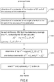
- Fig. 6 represents the flowchart of a method of a method of joint beam selection and transmission resource partitioning, according to a second embodiment of the invention.
- priority is given to localization for the allocation of transmission resources.
- Steps 610 and 620 are identical to steps 510 and 520, respectively. Hence, their description of these steps and their variants will be omitted here.
- the BS calculates the partition factor, ⁇ k loc * , maximizing the localization performance indicator, that is maximizing f loc (j,k,d ⁇ , ⁇ , ⁇ d , ⁇ d , ⁇ ⁇ , ⁇ ) taken as a function of ⁇ , while meeting the constraint on the communication performance constraint f com ( k, ⁇ ) ⁇ ⁇ where ⁇ is a predetermined performance threshold.
- the optimal beam at the BS is therefore the beam B j , k * and the optimal partition factor is ⁇ k * loc * .
- the optimal partition factor is used for partitioning the transmission resources respectively devoted to data communication and to localization (in the next frame).
- just enough transmission resources are allocated to satisfy a priori communication performance constraints while the rest of them is allocated for full-extent maximization of the localization performance.
- the optimal partition factor, ⁇ k * loc * is sent to the UE.
- the optimal beamwidth, ⁇ k * of the beam at the BS side is sent along with the optimal partition factor ⁇ k * loc * to the UE.
- the above described process can be periodically repeated during the localization phase.
- the joint optimization process can alternatively, but less preferably, be carried out at the UE, the result of the joint optimization, namely the optimal partition factor, ⁇ k * com * , and the optimal beamwidth, ⁇ k * , being then sent to the BS.
- Fig. 5 and 6 illustrate a joint optimization process of beam selection and transmission resource partitioning, based on UE centric performance indicators.
- these performance indicators can be averaged on all the UEs simultaneously served by the cell.
- the determination of the optimal partition factor be it according to the first or the second embodiment can therefore take into account all the UEs together.
- This optimization process can be performed sequentially one UE after the other, or carried out in parallel for all the users.
- a single global optimal partitioning factor can be determined for all the UEs of the cell served by the BS.
- Fig. 7 represents an example of behaviour of a communication performance indicator vs. an inverse localization performance indicator for different deployment densities and beam dictionary sizes.
- Fig. 7 represents the effective rate coverage probability of a UE with respect to the product of the BS beam selection error and the probability of misalignment of the UE and BS beams, for different SBS deployment densities and beam dictionary sizes, i.e., different values of N.
- the figure highlights the non-trivial trade-off between localization and data rate performance: to achieve high localization performance (i.e., a low error product), sufficient transmission resources need be allocated to the localization phase, thereby enabling efficient beam selection and accurate alignment.
- a small increase of the partition factor, ⁇ and hence a higher error product does not result in a large deterioration of the localization performance but, in contrast, may significantly enhance the communication performance.
- further increasing partition factor ⁇ beyond an optimal value deteriorates the communication performance. Indeed, allocating too many transmission resources to the communication phase leaves insufficient resources to the localization phase.
- the high beam error and poor beam alignment and therefore low SINR deteriorates the performance of the communication despite of the higher number of resources allocated thereto.
- the error product is slightly larger for larger beam dictionaries.
- the higher the size N of the beam dictionary the thinner the beams and hence the larger the probability that the UE would lie outside the serving BS beam or the probability that the beams are misaligned.
- the system parameters e.g., the antenna gains
- we do not have always the same trend i.e., by increasing the size N of the beam dictionary, we may improve the rate coverage as explained further below.
- Figs. 8A and 8B represent examples of behaviour of a communication performance indicator vs. a resource partitioning factor for different beam dictionary sizes.
- ⁇ k * com * there exists an optimum value, ⁇ k * com * , of the partitioning factor for each dictionary size for which the rate coverage probability is maximized.
- the optimum value ⁇ k * com * not only depends upon the dictionary size but also on the system parameters such as the antenna gains. From Fig. 8A , it can be seen that optimum value ⁇ k * com * decreases with the dictionary size. Indeed, the thinner the beamwidth, the more transmission resources have to be allocated to localization in order to cap the probability that the UE lies outside the coverage of the serving beam.
- the behavior of the rate coverage vs. the partitioning factor differs when the antenna gain, G 0 , is low or high.
- the rate coverage increases with the partitioning factor whereas, when the antenna gain is high, the rate coverage increases until it reaches a maximum and sharply decreases.
- the selection error and the beam misalignment large main lobe
- Fig. 9A represents the optimal value of the partitioning factor for different values of the deployment density and different noise levels affecting the quality of the localization estimates at the UE.
- the optimal value is obtained by giving priority to data communication for the allocation of transmission resources, according to Fig. 5 .
- the noise level directly impacts the accuracy of the estimation of the location and the AoA: the higher the noise level, the higher the standard deviations ⁇ d and ⁇ ⁇ .
- the optimal partitioning factor is close to 1 for high deployment densities and low noise levels. This is due to the fact that at low noise levels and for densely deployed BSs, even a limited amount of transmission resources allocated to localization results in accurate location and beam alignment. Thus, the optimal solution is to allocate most of the transmission resources to data communication. Conversely, for sparsely deployed BSs, that is for low values of deployment density ⁇ , larger amount of transmission resources are required to obtain accurate location and beam alignment, even at low noise levels, thereby resulting in lower values of the optimal partitioning factor.
- the variation of the optimal partitioning factor is not monotonous at high noise levels. It is noted indeed that at high noise levels (e.g. at -20 dBW), the optimal partitioning factor increases at first with the deployment density and then decreases at higher deployment densities. This is due to the fact that, for dense deployment of BSs, in a context of high noise level, the effect of a beam selection error is more important because of the high level of interference induced by the neighbouring BSs. Hence, a lower value of ⁇ com* is needed for allocating more resources to localization.
- the optimal value is obtained by giving priority to data communication for the allocation of transmission resources, as in Fig. 5 .
- the optimal size of the beam dictionary does not vary monotonously anymore with the deployment density, see right part of the figure: at low densities, it increases with the deployment density, because larger antenna gains improve the rate coverage, and then decreases at high densities (beyond a deployment density threshold, ⁇ th ) because beam selection errors seriously increase the interference due to the neighbouring BSs.
Landscapes
- Engineering & Computer Science (AREA)
- Computer Networks & Wireless Communication (AREA)
- Signal Processing (AREA)
- Physics & Mathematics (AREA)
- General Physics & Mathematics (AREA)
- Radar, Positioning & Navigation (AREA)
- Remote Sensing (AREA)
- Mobile Radio Communication Systems (AREA)
Abstract
Description
- The present invention concerns the field of 5th generation (5G) of mobile wireless networks, especially those providing location-based services or functionalities.
- The high density of small cells and the use of mm-wave bands in the new generation (5G) of mobile networks will enable to localize user equipments (UEs) with an accuracy in the sub-meter range, thus clearly outperforming the present cellular network localization capabilities. The access to high accuracy location information allows new services and functionalities to be offered such as navigation, collision-avoidance for autonomous vehicles, and traffic monitoring to name a few.
- The estimation of the location information of the UEs can also be leveraged at the network side for improving beam selection and beam alignment between the UEs and their respective serving base stations, thereby enabling a more efficient use of the radio resources such as the cell effective throughput or the effective rate coverage probability as described in the paper of G. Ghatak et al. entitled "Coverage analysis and load balancing in HetNets with mm-wave multi-RAT small cells" published in IEEE Trans. on wireless communications, vol. 17, No. 5, pp. 3154-3169, May 2018.
- However, when relying on the communication system itself to obtain location information of the UEs, a large overhead is required in terms of transmission resources (e.g., intervals of time, frequency etc.) which can be detrimental to the achievable data rate, latency, battery lifetime of the UEs. Conversely, if a large amount of transmission resources is allocated to data communication (and thus if a reduced amount of resources is dedicated to localization), poor localization may lead to a lower signal to noise ratio (SNR) and, hence a poorer quality of service (QoS).
- Therefore, in 5G mobile networks, a trade-off has to be achieved when allocating transmission resources to UE localization and localization-assisted communication.
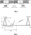
Fig. 1 illustrates a frame structure used in a small cell where the transmission resources (here timeslots) are partitioned between localization and localization-assisted communication. - More specifically, we assume that each frame comprises an initial access phase of length TI and a service phase of length TF, the latter being divided into a data service phase of length βTF and a localization phase of length (1 - β)TF where 0 < β < 1.
- The initial phase allows to determine the characteristics of a pair of Tx and Rx beams to establish a directive physical link in the mm-wave band between a UE and the SBS (Small cell Base Station) when the UE is admitted into the cell. It also generally provides an initial estimate of the position of the UE for the subsequent service phase.
- The data service phase is used for localization-assisted communication of the UEs. By localization-assisted communication of a UE, we mean here a communication using a location information of the UE, e.g., for selecting the beamwidth at the SBS side and/or improving the beam alignment between the UE and the SBS.
- The localization phase is dedicated to estimating and/or improving the location information of the UEs within the cell. This location information can be further used in the data service phase of the subsequent frame and/or to provide location-based service or a location-based functionality.
- The impact of localization performance during localization phase upon data rate performance in the data service phase has been investigated in the paper of G. Ghatak et al. entitled "Positioning data-rate trade-off in mm-wave small cells and service differentiation for 5G networks" published in Proc. IEEE VTC Spring, June 2018.
- However, no attempt has been made so far to jointly optimize beam selection and partition of transmission resources between localization and data communication. Hence, the object of present invention is to propose such a method of joint optimization, in particular for a mm-wave network.
- The present invention is defined by the appended independent claims. Various preferred embodiments are defined in the dependent claims.
- The present invention will be better understood from the description of the following embodiments, by way of illustration and in no way limitative thereto:
-
Fig. 1 , already described, schematically illustrates a frame structure used for both localization and localization-assisted communication services in a mm-wave network; -
Fig. 2 schematically illustrates a geometric model showing the position of a UE in a network; -
Fig. 3 schematically illustrates the coverage of a cell by beams of two beam dictionaries. -
Figs. 4A and 4B respectfully illustrate a beam selection error scenario and a beam misalignment error scenario; -
Fig. 5 represents the flowchart of a method of joint optimization of beam selection and transmission resource partitioning according to a first embodiment of the invention; -
Fig. 6 represents the flowchart of a method of joint optimization of beam selection and transmission resource partitioning according to a second embodiment of the invention; -
Fig. 7 represents an example of behaviour of a communication performance indicator vs. an inverse localization performance indicator for different deployment densities and beam dictionary sizes; -
Fig. 8A and 8B represent examples of behaviour of a communication performance indicator vs. a resource partitioning factor for different beam dictionary sizes; -
Fig. 9A represents the optimal value of the partitioning factor for different values of the deployment density and different noise levels; -
Fig. 9B represents the optimal dictionary size for different values of the deployment density and different noise levels. - Without loss of generality, the present invention will be described within the context of a 5G network. It will nevertheless be understood by the man skilled in the art that the invention is not limited to 5G networks and even not to mm-wave networks as referred to in the introductory part. The invention will more generally apply to a localization-assisted communication between a UE and its serving base station in a cellular network. By localization-assisted communication, it is meant a communication for which the location information of the UE is used to improve the performance of the communication e.g., by selecting a beamwidth at the BS side (and possibly also at the UE side) and pointing the directions of the BS and UE beams towards each other. The location information of the UE can also be leveraged to offer location-based services or functionalities as mentioned earlier.
- Typically, the 5G network comprises a layer of small cells which can communicate with the UE in the mm-wave band. It should be noted that this does not exclude a communication in another band, e.g., sub-6 GHz band or based on another technology as known in multi-RAT (Radio Access Technology) contexts.
- In order to simplify the presentation, and again without loss of generality, the invention will be explained with a 1D geometric model. Such a model is appropriate in case of BSs deployed along a road for example but in general a 2D or 3D geometric model will have to be taken into account. The extension to a 2D or 3D scenario does not invalidate the following conclusions, though.
-
Fig. 2 schematically illustrates a 1D geometric model showing position of a UE within the cellular network. - For convenience, the BS, 210, serving the UE is assumed to be located at the origin. The UE is located at a distance d of the serving base station, where d is assumed to be a sample of a random variable U uniformly distributed over


- Similarly, in case of a 2D geometric model for example, the position of the UE would be assumed to be sampled from a bidimensional random variable exhibiting a uniform distribution on a disk of radius and the position of the UE could be defined by the distance to the base station together with an angle with a line passing through
BSs - Turning back to the 1D model, the angle of departure of the signal transmitted by the serving BS is denoted φ, whereas the angle of arrival of the signal at the UE is denoted ψ. In other words, ψ is the angle between the pointing direction of the receiving beam and the direction of the incoming signal. In case of LOS (Line Of Sight), φ is the angle between the horizontal and the pointing direction of the transmitting beam. The angle between the receiving beam of the UE and the horizontal is denoted o.
- We will also assume in the following that the serving BS is provided with a plurality of beam dictionaries BD k, k =1,..,N. Each dictionary BD k is associated with a given beamwidth, θk and defines a set of beams of beamwidth θk and different orientations (or angles of departure), Bjk, j = 1,.., k Hence, each dictionary BD k can be defined as a list of pairs (θk,φj,k ), j = 1,.., k where φj,k, j = 1,.., k are the respective orientations of the beams. In case of the 1D model, dictionary BD k may alternatively be defined by a list of triplets


BSs - The plurality of beam dictionaries can be represented more concisely in a N×N matrix BD stacking the beam dictionaries. For example, where the triplet beam definition is adopted:

- Each row of matrix BD corresponds to a dictionary and each element of this row defines a beam belonging to this dictionary.
- The beams of a dictionary provide a complete coverage of the cell served by the BS. Consequently, the smaller the beamwidth θk, the higher the number N of beams in dictionary BD k .
-
Fig. 3 shows the coverage of a cell by beams belonging to a dictionary. - For the sake of simplicity, we have only represented one side of the 1D cell model. In practice, it will be understood that the cell may have beams pointing either to positive or negative directions. The invention is not restricted to a symmetrical or unsymmetrical angular distribution of beams though.
- The left part of the figure shows an example of cell coverage provided by beams belonging to BD 2, that is


- The right part of the figure shows an example of cell coverage provided by beams belonging to BD N, that is


- The partition Ω k of the cell induced by the beams of dictionary BD k can be expressed by a list of contiguous elementary coverage areas:


- Two main sources of errors may affect the choice of beam characteristics, such as beam pointing direction and beamwidth.
- The first source of errors relates to beam selection at the BS side. Indeed, relying on an estimate, d̂, of the position of the UE, the BS may select a beam of a dictionary which does not cover the UE, actually located at position d.
-
Fig. 4A represents a scenario of erroneous beam selection at the BS. The UE position estimate d̂ is found to be within ωj,k whereas it actually lies outside this range. - The probability of erroneously selecting beam Bj,k ∈ BD k can be expressed as follows:

- This probability of error depends on the position of the UE and will be therefore referred to as localization-based beam selection error. Assuming that the UE position estimate d̂ is a Gaussian random variable centered around d and of standard deviation σd , the localized-based beam selection error can be obtained by :

- The second source of errors relates to beamforming at the UE side. Indeed, relying on an estimate, ψ̂ of the angle of arrival (AoA) of the downlink signal, the UE may form a beam which is not directed to the actual angle of arrival ψ.
-
Fig. 4B represents a scenario of erroneous beamforming at the UE side. The BS has selected beam Bj,k and the UE has oriented the main lobe of the receive beam towards direction ψ̂ in order to align it with the main lobe of Bj,k . - The initial orientation of the UE receive beam is designated by oI. After having received pilot signals from the BS, the UE estimates the AoA and forms/ orientates the receive beam in direction oF .
- The probability of misaligning the receive beam with the main lobe of Bj,k can be expressed as follows:

- Assuming that ψ̂ is a Gaussian random variable centered around ψ and of standard deviation σψ, the localized-based beam alignment error can be obtained by :

- The
variance 
- Alternatively, the standard deviation σd can be empirically provided by a practical estimator out of received signals and/or sequences of range measurements.
- Similarly, the standard deviation σψ can be approximated by the CRLB or the ZZB related to any unbiased estimator of ψ, or empirically provided by a practical estimator out of received signals and/or sequences of AoA measurements.
- The present invention makes use of a communication performance indicator and of a localization performance indicator, respectively concerning the data service phase and the localization phase.
- The communication performance indicator indicates the quality of the downlink communication between the BS and the UE. It can be defined for example as the effective user throughput, the user SNR coverage probability or the user effective rate coverage probability. The effective user throughput is defined as the downlink data rate between the BS and the UE weighted by the probability of outage, Pout of the downlink with respect to a predetermined SNR (or SINR) threshold. The user SNR coverage probability is defined as the probability that the SNR (or SNIR) is higher than a predetermined threshold, γ 0. The user effective rate coverage probability is defined as the probability that the downlink data rate of the user is greater than a predetermined threshold, r 0.
- In general, assuming a predetermined beamwidth θU at the UE side, the communication performance indicator will depend on the beam selected in the dictionary, the UE location information estimate (d̂,ψ̂), and the accuracy of the estimation (σd,σψ ). It can be therefore denoted fcom (j,k,d̂,ψ̂,σd,σψ,β) and more simply fcom (k,β) in order to emphasize the dependency of the communication indicator upon the optimization parameters i.e., the beamwidth θk of the beam at the BS and the transmission resource partitioning factor, β.
- The localization performance indicator reflects the quality of the estimation of the location information of the user. A typical localization performance indicator can be defined as the inverse product of the probability of beam selection error and the probability of misalignment of the UE beam with the BS beam:

- As above, the localization performance indicator will be more simply denoted floc (k,β) in order to emphasize its dependency upon the optimization parameters, θk and β.
- It should be noted that the lower the beam selection error probability and the lower the beam misalignment probability, the higher the location performance indicator.
- The man skilled in the art will understand that alternative localization performance indicators could be envisaged. For example, the localization performance indicator can be defined as an (inverse) weighted product, a sum of logs or weighted logs, or a combination of the beam selection error probability and beam misalignment probability. In case of the localization performance indicator has to be calculated over a plurality of users, it may be computed according to a fairness criterion such as the min-max over the localization performance indicators of the UEs in question.
- Similarly, alternative communication performance indicators could be envisaged. For example, in case the communication performance indicator has to be calculated over a plurality of users, it may be computed according to an average an average effective throughput, the effective throughput of a user equipment being defined as a downlink data rate between the BS and this user equipment. According to another variant, it can be computed according to a proportional fairness indicator such as the average of the logarithms of the effective throughputs of the UEs in question.
- Other variants of these communication and localization performance indicators can be envisaged without falling outside the scope of the present invention.
- The communication and localization performance indicators have higher values for higher performances. Alternatively, we may use inverse performance indicators. For example, an inverse localization performance indicator would be the product of the probability of BS beam selection error and the probability of misalignment of the UE and BS beams, which should thus be minimized to get a higher performance.
-
Fig. 5 represents the flowchart of a method of joint beam selection and transmission resource partitioning, according to a first embodiment of the invention. - In this embodiment, priority is given to data communication for the allocation of transmission resources.
- The transmission resources can be for example time intervals in a frame structure as described above or a number of carriers in a frequency band, or a number of pilots in a time-frequency multiplexed scheme.
- The joint optimization is performed in each frame during the localization phase.
- At
step 510, the BS obtains an estimate, d̂, of the location of the UE. This location can be estimated at the UE from RSSI measurements of the downlink signal, the estimate being then sent to the BS. Alternatively, the location of the UE can be estimated at the BS from RSSI measurements of the uplink signal. A further option consists in performing delay estimation for both downlink and uplink received signals (resp. at UE and BS) so as to determine the round-trip time of flight. - The entity estimating the UE location also estimates the accuracy, σd , of the location measurement.
- As mentioned earlier, the accuracy of the UE location can be approximated by a Cramer-Rao bound or a Ziv-Zakai bound.
- At
step 520, the UE estimates the angle of arrival (AoA), ψ̂, from downlink pilot symbols received by a plurality of elementary antennas equipping the UE. The estimation of the AoA can be carried out at the UE and the result is then sent to the BS. Alternatively, the amplitude and phase information of the received pilot symbols can be sent to the BS for estimation of the AoA. In both cases, the entity in charge of the estimation of the AoA also estimates the accuracy, σψ , of this measurement. - As mentioned earlier, the accuracy of the AoA measurement can be approximated by a Cramer-Rao bound or a Ziv-Zakai bound.
- At
step 530, the BS looks up into each dictionary BD k , k =1,...,N for the respective elementary areas,

- At
step 540, the BS compares the values of the communication performance indicators

- This optimal partition factor is used for partitioning the transmission resources respectively devoted to data communication and localization in the next frame. In this embodiment, it is important to note that the just enough transmission resources are allocated to satisfy a priori localization performance constraints while the rest of them is allocated for full-extent maximization of the data communication performance, e.g., for maximization of the data rate.
- At
step 550, the optimal partition factor,
* , of the beam at the BS side is sent along with the optimal partition factory
- The above described process can be periodically repeated during the localization phase to take into account any important change in the system dynamics, such as the user position or the TX/RX beamwidth.
- The joint optimization process described above is carried out at the BS. Alternatively, but less preferably, the joint optimization process can be carried out at the UE, the result of the joint optimization, namely the optimal partition factor,

* , being then sent to the BS. - Alternatively, it can be carried out at a centralized controller (for example located at a macro-cell base station), the joint beam selection and partitioning of transmission resources then being obtained by marginalizing the communication and localization performance indicators over an a priori spatial distribution of the base stations and the related user equipments.
-
Fig. 6 represents the flowchart of a method of a method of joint beam selection and transmission resource partitioning, according to a second embodiment of the invention. - In this embodiment, priority is given to localization for the allocation of transmission resources.
-
Steps steps - At
step 630, the BS looks up into each dictionary BD k , k =1,...,N for the respective elementary areas,

- At
step 640, the BS compares the values of the location performance indicators
* and the optimal partition factor is
- As in the first embodiment, the optimal partition factor is used for partitioning the transmission resources respectively devoted to data communication and to localization (in the next frame). In this embodiment though, just enough transmission resources are allocated to satisfy a priori communication performance constraints while the rest of them is allocated for full-extent maximization of the localization performance.
- At
step 650, the optimal partition factor,
* , of the beam at the BS side is sent along with the optimal partition factor
- The above described process can be periodically repeated during the localization phase.
- As in the first embodiment, the joint optimization process can alternatively, but less preferably, be carried out at the UE, the result of the joint optimization, namely the optimal partition factor,

* , being then sent to the BS. - It can also be carried out at a centralized controller as mentioned above.
-
Fig. 5 and6 illustrate a joint optimization process of beam selection and transmission resource partitioning, based on UE centric performance indicators. However, the man skilled in the art will understand that these performance indicators can be averaged on all the UEs simultaneously served by the cell. The determination of the optimal partition factor, be it according to the first or the second embodiment can therefore take into account all the UEs together. This optimization process can be performed sequentially one UE after the other, or carried out in parallel for all the users. When carried out in parallel, a single global optimal partitioning factor can be determined for all the UEs of the cell served by the BS. -
Fig. 7 represents an example of behaviour of a communication performance indicator vs. an inverse localization performance indicator for different deployment densities and beam dictionary sizes. - More specifically,
Fig. 7 represents the effective rate coverage probability of a UE with respect to the product of the BS beam selection error and the probability of misalignment of the UE and BS beams, for different SBS deployment densities and beam dictionary sizes, i.e., different values of N. - It is noted that for different beam dictionary sizes, the effective rate coverage probability first increases with inverse localization performance (i.e. with decreasing localization performance) until it reaches a maximum and then gradually decreases. This is observed for various BS deployment densities, λ, as shown on the figure.
- The figure highlights the non-trivial trade-off between localization and data rate performance: to achieve high localization performance (i.e., a low error product), sufficient transmission resources need be allocated to the localization phase, thereby enabling efficient beam selection and accurate alignment. At first, a small increase of the partition factor, β, and hence a higher error product does not result in a large deterioration of the localization performance but, in contrast, may significantly enhance the communication performance. However, further increasing partition factor β beyond an optimal value deteriorates the communication performance. Indeed, allocating too many transmission resources to the communication phase leaves insufficient resources to the localization phase. The high beam error and poor beam alignment and therefore low SINR deteriorates the performance of the communication despite of the higher number of resources allocated thereto.
- It is also important to note that, in order to achieve the optimal rate coverage, the error product is slightly larger for larger beam dictionaries. Indeed, the higher the size N of the beam dictionary, the thinner the beams and hence the larger the probability that the UE would lie outside the serving BS beam or the probability that the beams are misaligned. However, when changing the system parameters, e.g., the antenna gains, we do not have always the same trend, i.e., by increasing the size N of the beam dictionary, we may improve the rate coverage as explained further below.
-
Figs. 8A and 8B represent examples of behaviour of a communication performance indicator vs. a resource partitioning factor for different beam dictionary sizes. - More specifically,
Figs. 8A and 8B represent the rate coverage probability for a downlink at 100 Mbps and 1 Mbs, respectively. The behaviour of the rate coverage is given for various BS antenna gains G0, g and dictionary sizes, N . G 0 stands for the gain of the main lobe in the pointing direction (i.e., the maximum value of the gain of the antenna) of the BS beam and g for the gain of its highest side lobe. - First, it should be noted that there exists an optimum value,


Fig. 8A , it can be seen that optimum value
- Second, the behavior of the rate coverage vs. the partitioning factor differs when the antenna gain, G 0, is low or high. When the antenna gain is low, the rate coverage increases with the partitioning factor whereas, when the antenna gain is high, the rate coverage increases until it reaches a maximum and sharply decreases. This can be explained by the fact that at low gain the selection error and the beam misalignment (large main lobe) play little role in the communication performance, the latter essentially depending upon the allocation of resources to transmission. Moreover, in the instance of low antenna gains, for a given deployment density, a beam dictionary of larger size, corresponding to a smaller beamwidth, leads to a slightly higher rate coverage probability because of the higher radiated power and hence higher SINR.
-
Fig. 9A represents the optimal value of the partitioning factor for different values of the deployment density and different noise levels affecting the quality of the localization estimates at the UE. - In the present instance, the optimal value is obtained by giving priority to data communication for the allocation of transmission resources, according to
Fig. 5 . - The noise level directly impacts the accuracy of the estimation of the location and the AoA: the higher the noise level, the higher the standard deviations σd and σψ .
- It appears from the figure that the optimal partitioning factor is close to 1 for high deployment densities and low noise levels. This is due to the fact that at low noise levels and for densely deployed BSs, even a limited amount of transmission resources allocated to localization results in accurate location and beam alignment. Thus, the optimal solution is to allocate most of the transmission resources to data communication. Conversely, for sparsely deployed BSs, that is for low values of deployment density λ, larger amount of transmission resources are required to obtain accurate location and beam alignment, even at low noise levels, thereby resulting in lower values of the optimal partitioning factor.
- By contrast, the variation of the optimal partitioning factor is not monotonous at high noise levels. It is noted indeed that at high noise levels (e.g. at -20 dBW), the optimal partitioning factor increases at first with the deployment density and then decreases at higher deployment densities. This is due to the fact that, for dense deployment of BSs, in a context of high noise level, the effect of a beam selection error is more important because of the high level of interference induced by the neighbouring BSs. Hence, a lower value of βcom* is needed for allocating more resources to localization.
-
Fig. 9B represents the optimal dictionary size for different deployment densities and different noise levels. - Here again, the optimal value is obtained by giving priority to data communication for the allocation of transmission resources, as in
Fig. 5 . - It can be seen from the left part of the figure that, at high noise levels, large beams have to be used in order to avoid beam selection errors, resulting in a small optimal size, N*, of the beam dictionary.
- By contrast, at low noise levels, the optimal size of the beam dictionary does not vary monotonously anymore with the deployment density, see right part of the figure: at low densities, it increases with the deployment density, because larger antenna gains improve the rate coverage, and then decreases at high densities (beyond a deployment density threshold, λth ) because beam selection errors seriously increase the interference due to the neighbouring BSs.
Claims (15)
- Method of joint beam selection and partitioning of transmission resources for a downlink between a base station (BS) and a user equipment (UE) in a cellular network, the transmission resources being partitioned with a partitioning factor, β between a data communication service, in which data are transmitted on the downlink, and a localization service, in which the UE is localized, the BS comprising a memory in which are stored a plurality of beam dictionaries, BD k, k = 1,.., N, each dictionary BD k being associated with a given beamwidth θk and defining a set of beams having the same beamwidth and different orientations, wherein(a) the BS is provided with an estimate (d̂) of the position of the UE along with a standard deviation (σd ) of this estimate (510);(b) the BS is provided with an estimate of the angle of arrival (ψ̂) of the signal at the UE along with a standard deviation (σψ ) of this estimate (520);(c) for each beam dictionary, BD k, k = 1,.., N and a BS beam of this dictionary having a coverage area including the UE, it is determined (530) a partitioning factor,
 (d) the beam dictionary,

* , having a coverage area including the UE;(e) the optimal partitioning factor is sent by the BS to the UE (550). - Method of joint beam selection and partitioning of transmission resources for a downlink between a base station (BS) and a user equipment (UE) in a cellular network, the transmission resources being partitioned with a partitioning factor, β, between a data communication service, in which data are transmitted on the downlink, and a localization service, in which the UE is localized, the BS comprising a memory in which are stored a plurality of beam dictionaries, BD k, k = 1,.., N, each dictionary BD k being associated with a given beamwidth θk and defining a set of beams having the same beamwidth and different orientations, wherein(a) the BS is provided with an estimate (d̂) of the position of the UE along with a standard deviation (σ d ) of this estimate (610);(b) the BS is provided with an estimate of the angle of arrival (ψ̂) of the signal at the UE along with a standard deviation (σψ ) of this estimate (620);(c) for each beam dictionary, BD k, k = 1,.., N and a selected BS beam within this dictionary having a coverage area including the UE, it is determined (630) a partitioning factor, which maximizes a localization performance indicator floc (k, β) while meeting a predetermined constraint of a communication performance indicator fcom (k, β);(d) the beam dictionary, , corresponding to the highest value of the localization performance indicators

* , having a coverage area including the UE;(e) the optimal partitioning factor is sent by the BS to the UE (650). - Method of joint beam selection and partitioning of transmission resources for a downlink between a base station and a user equipment in a cellular network according to claim 1 or 2, characterized in that the optimal beamwidth (θ com*, θloc* ) corresponding to the selected beam dictionary, BD k
* , is sent to the UE, along with the optimal partitioning dictionary (βcom* , βloc* ). - Method of joint beam selection and partitioning of transmission resources for a downlink between a base station and a user equipment in a cellular network according to any preceding claim, characterized in that the communication performance indicator is an effective throughput of the UE defined as the downlink data rate between the BS and the UE weighted by the probability of outage of the downlink with respect to a predetermined threshold of signal to noise and interference ratio.
- Method of joint beam selection and partitioning of transmission resources for a downlink between a base station and a user equipment in a cellular network according to any of claims 1 to 3, characterized in that the communication performance indicator is an average effective throughput, the effective throughput of a user equipment being defined as a downlink data rate between the BS and this user equipment, the downlink data rate being weighted by the probability of outage of the downlink with respect to a predetermined threshold of signal to noise and interference ratio, the average being calculated over a plurality of user equipments simultaneously served by the BS.
- Method of joint beam selection and partitioning of transmission resources for a downlink between a base station and a user equipement in a cellular network according to any of claims 1 to 3, characterized in that the communication performance indicator is a proportional fairness indicator calculated as an average of the logarithms of effective throughputs, the effective throughput of a user equipment being defined as a downlink data rate between the BS and this user equipment, the downlink data rate being weighted by the probability of outage of the downlink with respect to a predetermined threshold of signal to noise and interference ratio, the average of the logarithms of effective throughputs being calculated over the user equipments simultaneously served by the BS.
- Method of joint beam selection and partitioning of transmission resources for a downlink between a base station and a user equipment in a cellular network according to any of claims 1 to 3, characterized in that the communication performance indicator is an effective rate coverage probability, defined as the probability that the downlink data rate of the UE is greater than a predetermined threshold.
- Method of joint beam selection and partitioning of transmission resources for a downlink between a base station and a user equipment in a cellular network according to any of claims 1 to 3, characterized in that the communication performance indicator is an average effective rate coverage probability, the effective rate coverage probability of a user equipment being defined as the probability that the downlink data rate of this user equipment is greater than a predetermined threshold, the average being taken over the user equipments simultaneously served by the BS.
- Method of joint beam selection and partitioning of transmission resources for a downlink between a base station and a user equipment in a cellular network according to any of the preceding claims, characterized in that the transmission resources are time intervals in a frame structure, a number of carriers in a frequency band, or a number of pilots in a time-frequency multiplexed scheme.
- Method of joint beam selection and partitioning of transmission resources for a downlink between a base station and a user equipment in a cellular network according to any of the preceding claims, characterized in that the localization performance indicator is the inverse of the product of a probability of a beam selection error in the beam dictionary and of the probability of a misalignment between the selected BS beam and a receiving beam of the UE.
- Method of joint beam selection and partitioning of transmission resources for a downlink between a base station and a user equipment in a cellular network according to any of the preceding claims, characterized in that, at steps (a) and (b), the BS sends downlink pilot signals, the UE acquires phase and amplitude information of the received downlink pilot signals and sends this information back to the BS, and the BS estimates from this information the range of the UE as well as the angle of arrival of the downlink signal at the UE side.
- Method of joint beam selection and partitioning of transmission resources for a downlink between a base station and a user equipment in a cellular network according to any of claims 1-10, characterized in that, at steps (a) and (b), the BS sends downlink pilot signals, the UE acquires phase and amplitude information of the received downlink, estimates from this information, its range as well as the angle of arrival of the downlink signal, and sends back to the BS the range and angle of arrival thus estimated.
- Method of joint beam selection and partitioning of transmission resources for a downlink between a base station and a user equipment in a cellular network according to any of the preceding claims, characterized in that the standard deviation of the position and/or the standard deviation of the angle of arrival are approximated by a Cramer-Rao bound or a Ziv-Zakai bound.
- Method of joint beam selection and partitioning of transmission resources for a downlink between a base station and a user equipment in a cellular network according to any of the preceding claims, characterized in that the cellular network is a mm-wave cellular network.
- Method of joint beam selection and partitioning of transmission resources for a downlink between a base station and a user equipment in a cellular network according to claim 14, characterized in that the mm-wave cellular network is the small cell layer of a 5G network.
Priority Applications (2)
| Application Number | Priority Date | Filing Date | Title |
|---|---|---|---|
| EP19218790.4A EP3840450B1 (en) | 2019-12-20 | 2019-12-20 | Joint beam selection and resource partitioning in a mm-wave network |
| US17/120,430 US11297620B2 (en) | 2019-12-20 | 2020-12-14 | Joint beam selection and resource partitioning in a mm-wave network |
Applications Claiming Priority (1)
| Application Number | Priority Date | Filing Date | Title |
|---|---|---|---|
| EP19218790.4A EP3840450B1 (en) | 2019-12-20 | 2019-12-20 | Joint beam selection and resource partitioning in a mm-wave network |
Publications (2)
| Publication Number | Publication Date |
|---|---|
| EP3840450A1 true EP3840450A1 (en) | 2021-06-23 |
| EP3840450B1 EP3840450B1 (en) | 2022-12-14 |
Family
ID=69005292
Family Applications (1)
| Application Number | Title | Priority Date | Filing Date |
|---|---|---|---|
| EP19218790.4A Active EP3840450B1 (en) | 2019-12-20 | 2019-12-20 | Joint beam selection and resource partitioning in a mm-wave network |
Country Status (2)
| Country | Link |
|---|---|
| US (1) | US11297620B2 (en) |
| EP (1) | EP3840450B1 (en) |
Cited By (2)
| Publication number | Priority date | Publication date | Assignee | Title |
|---|---|---|---|---|
| CN116367332A (en) * | 2023-05-31 | 2023-06-30 | 华信咨询设计研究院有限公司 | Hierarchical control-based D2D resource allocation method under 5G system |
| CN116567645A (en) * | 2023-05-12 | 2023-08-08 | 郑州大学 | Safe energy efficiency robust design method in intelligent reflection surface-assisted cellular network |
Families Citing this family (3)
| Publication number | Priority date | Publication date | Assignee | Title |
|---|---|---|---|---|
| US12143183B2 (en) * | 2022-02-28 | 2024-11-12 | Nokia Solutions And Networks Oy | Beam and antenna array split configuration optimization |
| CN115276932B (en) * | 2022-06-02 | 2023-06-23 | 敦煌研究院 | A sub-channel allocation method in millimeter wave access and backhaul integrated network |
| CN116095823A (en) * | 2022-12-12 | 2023-05-09 | 杭州援宇科技有限公司 | Wave beam forming method for millimeter wave frequency band joint communication and positioning |
Citations (2)
| Publication number | Priority date | Publication date | Assignee | Title |
|---|---|---|---|---|
| US20170318590A1 (en) * | 2014-11-04 | 2017-11-02 | Lg Electronics Inc. | Signal transmission method and device |
| CN110166100A (en) * | 2019-05-09 | 2019-08-23 | 南京邮电大学 | Millimeter wave high-speed rail train-ground communication based on position justice stablizes beam-forming method |
Family Cites Families (11)
| Publication number | Priority date | Publication date | Assignee | Title |
|---|---|---|---|---|
| US7203520B2 (en) * | 2003-09-30 | 2007-04-10 | Nortel Networks Limited | Beam wobbling for increased downlink coverage and capacity |
| US9077649B2 (en) * | 2012-05-29 | 2015-07-07 | Verizon Patent And Licensing Inc. | Split customer premises equipment architecture for provisioning fixed wireless broadband services |
| KR20140045752A (en) * | 2012-10-09 | 2014-04-17 | 삼성전자주식회사 | Apparatus and mehtod for transmitting/receiving feedback information in a wireless communiation system using beamforming |
| WO2014208844A1 (en) * | 2013-06-28 | 2014-12-31 | 중앙대학교 산학협력단 | Beam training device and method |
| US10348117B2 (en) * | 2015-10-01 | 2019-07-09 | Motorola Mobility Llc | Antenna configuration change based on charging pad coupling |
| US10560851B2 (en) * | 2017-01-13 | 2020-02-11 | Samsung Electronics Co., Ltd. | Method and apparatus for uplink beam management in next generation wireless systems |
| CA3064628C (en) * | 2017-05-27 | 2022-05-24 | Guangdong Oppo Mobile Telecommunications Corp., Ltd. | Wireless communication method and device |
| US11087013B2 (en) * | 2018-01-22 | 2021-08-10 | Alitheon, Inc. | Secure digital fingerprint key object database |
| EP3749975A1 (en) * | 2018-02-08 | 2020-12-16 | Sony Corporation | Position estimation device and communication device |
| US11357053B2 (en) * | 2018-05-21 | 2022-06-07 | Comcast Cable Communications, Llc | Random access procedures using multiple active bandwidth parts |
| US11671971B2 (en) * | 2019-12-03 | 2023-06-06 | Samsung Electronics Co., Ltd. | Method and system for allocating resource in wireless communication network |
-
2019
- 2019-12-20 EP EP19218790.4A patent/EP3840450B1/en active Active
-
2020
- 2020-12-14 US US17/120,430 patent/US11297620B2/en not_active Expired - Fee Related
Patent Citations (2)
| Publication number | Priority date | Publication date | Assignee | Title |
|---|---|---|---|---|
| US20170318590A1 (en) * | 2014-11-04 | 2017-11-02 | Lg Electronics Inc. | Signal transmission method and device |
| CN110166100A (en) * | 2019-05-09 | 2019-08-23 | 南京邮电大学 | Millimeter wave high-speed rail train-ground communication based on position justice stablizes beam-forming method |
Non-Patent Citations (3)
| Title |
|---|
| G. GHATAK: "Coverage analysis and load balancing in HetNets with mm-wave multi-RAT small cells", IEEE TRANS. ON WIRELESS COMMUNICATIONS, vol. 17, no. 5, May 2018 (2018-05-01), pages 3154 - 3169, XP011683453, DOI: 10.1109/TWC.2018.2807426 |
| G. GHATAK: "Positioning data-rate trade-off in mm-wave small cells and service differentiation for 5G networks", PROC. IEEE VTC SPRING, June 2018 (2018-06-01) |
| G. GHATAK: "Positioning data-rate trade-off in mm-wave small cells and service differentiation for 5G networks", PROC. IEEE VTC SPRING, June 2018 (2018-06-01), XP002799154 * |
Cited By (3)
| Publication number | Priority date | Publication date | Assignee | Title |
|---|---|---|---|---|
| CN116567645A (en) * | 2023-05-12 | 2023-08-08 | 郑州大学 | Safe energy efficiency robust design method in intelligent reflection surface-assisted cellular network |
| CN116367332A (en) * | 2023-05-31 | 2023-06-30 | 华信咨询设计研究院有限公司 | Hierarchical control-based D2D resource allocation method under 5G system |
| CN116367332B (en) * | 2023-05-31 | 2023-09-15 | 华信咨询设计研究院有限公司 | Hierarchical control-based D2D resource allocation method under 5G system |
Also Published As
| Publication number | Publication date |
|---|---|
| US20210195571A1 (en) | 2021-06-24 |
| US11297620B2 (en) | 2022-04-05 |
| EP3840450B1 (en) | 2022-12-14 |
Similar Documents
| Publication | Publication Date | Title |
|---|---|---|
| EP3840450B1 (en) | Joint beam selection and resource partitioning in a mm-wave network | |
| US20230189315A1 (en) | Interference detection and handling | |
| CN109845122B (en) | Diagram of a millimeter-wavelength network including codebook constraints for use in beamforming | |
| CN106576265B (en) | Method and apparatus for measuring and reporting beams in a beamforming based system | |
| US9565010B2 (en) | Method and apparatus for handling inter-cell interference | |
| US7609661B2 (en) | System and method for controlling uplink traffic load in a cellular wireless mobile communication system | |
| Kela et al. | Borderless mobility in 5G outdoor ultra-dense networks | |
| US20190215842A1 (en) | Resource allocation for ofdma with preservation of wireless location accuracy | |
| US12574083B2 (en) | Reduced overhead beam profile parametrization | |
| EP1869797B1 (en) | High rate packet data spatial division multiple access (sdma) | |
| US20230068248A1 (en) | Ai/ml based ss burst set & csi-rs trs configuration optimization and improving nr network power and spectral efficiency | |
| US9538387B2 (en) | Radio resource assignment coordination in superdense networks | |
| Satchidanandan et al. | TrackMAC: An IEEE 802.11 ad-compatible beam tracking-based MAC protocol for 5G millimeter-wave local area networks | |
| EP3840243A1 (en) | Iterative beam training method for accessing a mm-wave network | |
| EP4161123A1 (en) | Wireless communication method, terminal, base station, system, electronic device and medium | |
| Kuboniwa et al. | High efficient network selection scheme using location information for heterogeneous wireless system | |
| EP4256839B1 (en) | Method, apparatus and computer program for machine learning-assisted beams coordinated scheduling in 5g and beyond | |
| KR20230131201A (en) | Reduced overhead beam profile characterization | |
| US12328605B2 (en) | Systems and methods for wireless channel information sharing | |
| US12634713B2 (en) | Apparatus and method for performing beam selection in communication system for supporting satellite networks | |
| US20240397340A1 (en) | Apparatus and method for performing beam selection in communication system for supporting satellite networks | |
| Xu et al. | Performance modeling for IEEE 802.11 vehicle-to-infrastructure networks with directional antennas | |
| Ravichandran et al. | Study on Autonomous Resource Selection in Sidelink Vehicular Communication on mmWave and Sub-THz in 6G | |
| Peng et al. | SNR Based Beam Switching in Millimeter Wave Vehicular Communications | |
| Koirala et al. | Throughput characterization and beamwidth selection for positioning-assisted mmwave service |
Legal Events
| Date | Code | Title | Description |
|---|---|---|---|
| PUAI | Public reference made under article 153(3) epc to a published international application that has entered the european phase |
Free format text: ORIGINAL CODE: 0009012 |
|
| STAA | Information on the status of an ep patent application or granted ep patent |
Free format text: STATUS: REQUEST FOR EXAMINATION WAS MADE |
|
| 17P | Request for examination filed |
Effective date: 20191220 |
|
| AK | Designated contracting states |
Kind code of ref document: A1 Designated state(s): AL AT BE BG CH CY CZ DE DK EE ES FI FR GB GR HR HU IE IS IT LI LT LU LV MC MK MT NL NO PL PT RO RS SE SI SK SM TR |
|
| GRAP | Despatch of communication of intention to grant a patent |
Free format text: ORIGINAL CODE: EPIDOSNIGR1 |
|
| RIC1 | Information provided on ipc code assigned before grant |
Ipc: H04W 24/02 20090101ALN20220601BHEP Ipc: H04W 64/00 20090101ALN20220601BHEP Ipc: H04W 16/28 20090101AFI20220601BHEP |
|
| STAA | Information on the status of an ep patent application or granted ep patent |
Free format text: STATUS: GRANT OF PATENT IS INTENDED |
|
| RIC1 | Information provided on ipc code assigned before grant |
Ipc: H04W 24/02 20090101ALN20220623BHEP Ipc: H04W 64/00 20090101ALN20220623BHEP Ipc: H04W 16/28 20090101AFI20220623BHEP |
|
| INTG | Intention to grant announced |
Effective date: 20220707 |
|
| GRAS | Grant fee paid |
Free format text: ORIGINAL CODE: EPIDOSNIGR3 |
|
| GRAA | (expected) grant |
Free format text: ORIGINAL CODE: 0009210 |
|
| STAA | Information on the status of an ep patent application or granted ep patent |
Free format text: STATUS: THE PATENT HAS BEEN GRANTED |
|
| AK | Designated contracting states |
Kind code of ref document: B1 Designated state(s): AL AT BE BG CH CY CZ DE DK EE ES FI FR GB GR HR HU IE IS IT LI LT LU LV MC MK MT NL NO PL PT RO RS SE SI SK SM TR |
|
| REG | Reference to a national code |
Ref country code: GB Ref legal event code: FG4D |
|
| REG | Reference to a national code |
Ref country code: CH Ref legal event code: EP |
|
| REG | Reference to a national code |
Ref country code: DE Ref legal event code: R096 Ref document number: 602019023118 Country of ref document: DE |
|
| REG | Reference to a national code |
Ref country code: IE Ref legal event code: FG4D |
|
| REG | Reference to a national code |
Ref country code: AT Ref legal event code: REF Ref document number: 1538398 Country of ref document: AT Kind code of ref document: T Effective date: 20230115 |
|
| REG | Reference to a national code |
Ref country code: LT Ref legal event code: MG9D |
|
| REG | Reference to a national code |
Ref country code: NL Ref legal event code: MP Effective date: 20221214 |
|
| PG25 | Lapsed in a contracting state [announced via postgrant information from national office to epo] |
Ref country code: SE Free format text: LAPSE BECAUSE OF FAILURE TO SUBMIT A TRANSLATION OF THE DESCRIPTION OR TO PAY THE FEE WITHIN THE PRESCRIBED TIME-LIMIT Effective date: 20221214 Ref country code: NO Free format text: LAPSE BECAUSE OF FAILURE TO SUBMIT A TRANSLATION OF THE DESCRIPTION OR TO PAY THE FEE WITHIN THE PRESCRIBED TIME-LIMIT Effective date: 20230314 Ref country code: LT Free format text: LAPSE BECAUSE OF FAILURE TO SUBMIT A TRANSLATION OF THE DESCRIPTION OR TO PAY THE FEE WITHIN THE PRESCRIBED TIME-LIMIT Effective date: 20221214 Ref country code: FI Free format text: LAPSE BECAUSE OF FAILURE TO SUBMIT A TRANSLATION OF THE DESCRIPTION OR TO PAY THE FEE WITHIN THE PRESCRIBED TIME-LIMIT Effective date: 20221214 |
|
| REG | Reference to a national code |
Ref country code: AT Ref legal event code: MK05 Ref document number: 1538398 Country of ref document: AT Kind code of ref document: T Effective date: 20221214 |
|
| PG25 | Lapsed in a contracting state [announced via postgrant information from national office to epo] |
Ref country code: RS Free format text: LAPSE BECAUSE OF FAILURE TO SUBMIT A TRANSLATION OF THE DESCRIPTION OR TO PAY THE FEE WITHIN THE PRESCRIBED TIME-LIMIT Effective date: 20221214 Ref country code: LV Free format text: LAPSE BECAUSE OF FAILURE TO SUBMIT A TRANSLATION OF THE DESCRIPTION OR TO PAY THE FEE WITHIN THE PRESCRIBED TIME-LIMIT Effective date: 20221214 Ref country code: HR Free format text: LAPSE BECAUSE OF FAILURE TO SUBMIT A TRANSLATION OF THE DESCRIPTION OR TO PAY THE FEE WITHIN THE PRESCRIBED TIME-LIMIT Effective date: 20221214 Ref country code: GR Free format text: LAPSE BECAUSE OF FAILURE TO SUBMIT A TRANSLATION OF THE DESCRIPTION OR TO PAY THE FEE WITHIN THE PRESCRIBED TIME-LIMIT Effective date: 20230315 |
|
| PG25 | Lapsed in a contracting state [announced via postgrant information from national office to epo] |
Ref country code: NL Free format text: LAPSE BECAUSE OF FAILURE TO SUBMIT A TRANSLATION OF THE DESCRIPTION OR TO PAY THE FEE WITHIN THE PRESCRIBED TIME-LIMIT Effective date: 20221214 |
|
| PG25 | Lapsed in a contracting state [announced via postgrant information from national office to epo] |
Ref country code: SM Free format text: LAPSE BECAUSE OF FAILURE TO SUBMIT A TRANSLATION OF THE DESCRIPTION OR TO PAY THE FEE WITHIN THE PRESCRIBED TIME-LIMIT Effective date: 20221214 Ref country code: RO Free format text: LAPSE BECAUSE OF FAILURE TO SUBMIT A TRANSLATION OF THE DESCRIPTION OR TO PAY THE FEE WITHIN THE PRESCRIBED TIME-LIMIT Effective date: 20221214 Ref country code: PT Free format text: LAPSE BECAUSE OF FAILURE TO SUBMIT A TRANSLATION OF THE DESCRIPTION OR TO PAY THE FEE WITHIN THE PRESCRIBED TIME-LIMIT Effective date: 20230414 Ref country code: ES Free format text: LAPSE BECAUSE OF FAILURE TO SUBMIT A TRANSLATION OF THE DESCRIPTION OR TO PAY THE FEE WITHIN THE PRESCRIBED TIME-LIMIT Effective date: 20221214 Ref country code: EE Free format text: LAPSE BECAUSE OF FAILURE TO SUBMIT A TRANSLATION OF THE DESCRIPTION OR TO PAY THE FEE WITHIN THE PRESCRIBED TIME-LIMIT Effective date: 20221214 Ref country code: CZ Free format text: LAPSE BECAUSE OF FAILURE TO SUBMIT A TRANSLATION OF THE DESCRIPTION OR TO PAY THE FEE WITHIN THE PRESCRIBED TIME-LIMIT Effective date: 20221214 Ref country code: AT Free format text: LAPSE BECAUSE OF FAILURE TO SUBMIT A TRANSLATION OF THE DESCRIPTION OR TO PAY THE FEE WITHIN THE PRESCRIBED TIME-LIMIT Effective date: 20221214 |
|
| REG | Reference to a national code |
Ref country code: CH Ref legal event code: PL |
|
| REG | Reference to a national code |
Ref country code: BE Ref legal event code: MM Effective date: 20221231 |
|
| PG25 | Lapsed in a contracting state [announced via postgrant information from national office to epo] |
Ref country code: SK Free format text: LAPSE BECAUSE OF FAILURE TO SUBMIT A TRANSLATION OF THE DESCRIPTION OR TO PAY THE FEE WITHIN THE PRESCRIBED TIME-LIMIT Effective date: 20221214 Ref country code: PL Free format text: LAPSE BECAUSE OF FAILURE TO SUBMIT A TRANSLATION OF THE DESCRIPTION OR TO PAY THE FEE WITHIN THE PRESCRIBED TIME-LIMIT Effective date: 20221214 Ref country code: LU Free format text: LAPSE BECAUSE OF NON-PAYMENT OF DUE FEES Effective date: 20221220 Ref country code: IS Free format text: LAPSE BECAUSE OF FAILURE TO SUBMIT A TRANSLATION OF THE DESCRIPTION OR TO PAY THE FEE WITHIN THE PRESCRIBED TIME-LIMIT Effective date: 20230414 Ref country code: AL Free format text: LAPSE BECAUSE OF FAILURE TO SUBMIT A TRANSLATION OF THE DESCRIPTION OR TO PAY THE FEE WITHIN THE PRESCRIBED TIME-LIMIT Effective date: 20221214 |
|
| REG | Reference to a national code |
Ref country code: DE Ref legal event code: R097 Ref document number: 602019023118 Country of ref document: DE |
|
| PG25 | Lapsed in a contracting state [announced via postgrant information from national office to epo] |
Ref country code: MC Free format text: LAPSE BECAUSE OF FAILURE TO SUBMIT A TRANSLATION OF THE DESCRIPTION OR TO PAY THE FEE WITHIN THE PRESCRIBED TIME-LIMIT Effective date: 20221214 |
|
| PLBE | No opposition filed within time limit |
Free format text: ORIGINAL CODE: 0009261 |
|
| STAA | Information on the status of an ep patent application or granted ep patent |
Free format text: STATUS: NO OPPOSITION FILED WITHIN TIME LIMIT |
|
| PG25 | Lapsed in a contracting state [announced via postgrant information from national office to epo] |
Ref country code: LI Free format text: LAPSE BECAUSE OF NON-PAYMENT OF DUE FEES Effective date: 20221231 Ref country code: IE Free format text: LAPSE BECAUSE OF NON-PAYMENT OF DUE FEES Effective date: 20221220 Ref country code: DK Free format text: LAPSE BECAUSE OF FAILURE TO SUBMIT A TRANSLATION OF THE DESCRIPTION OR TO PAY THE FEE WITHIN THE PRESCRIBED TIME-LIMIT Effective date: 20221214 Ref country code: CH Free format text: LAPSE BECAUSE OF NON-PAYMENT OF DUE FEES Effective date: 20221231 |
|
| 26N | No opposition filed |
Effective date: 20230915 |
|
| PG25 | Lapsed in a contracting state [announced via postgrant information from national office to epo] |
Ref country code: SI Free format text: LAPSE BECAUSE OF FAILURE TO SUBMIT A TRANSLATION OF THE DESCRIPTION OR TO PAY THE FEE WITHIN THE PRESCRIBED TIME-LIMIT Effective date: 20221214 Ref country code: BE Free format text: LAPSE BECAUSE OF NON-PAYMENT OF DUE FEES Effective date: 20221231 |
|
| PG25 | Lapsed in a contracting state [announced via postgrant information from national office to epo] |
Ref country code: CY Free format text: LAPSE BECAUSE OF FAILURE TO SUBMIT A TRANSLATION OF THE DESCRIPTION OR TO PAY THE FEE WITHIN THE PRESCRIBED TIME-LIMIT Effective date: 20221214 |
|
| PG25 | Lapsed in a contracting state [announced via postgrant information from national office to epo] |
Ref country code: MK Free format text: LAPSE BECAUSE OF FAILURE TO SUBMIT A TRANSLATION OF THE DESCRIPTION OR TO PAY THE FEE WITHIN THE PRESCRIBED TIME-LIMIT Effective date: 20221214 Ref country code: IT Free format text: LAPSE BECAUSE OF FAILURE TO SUBMIT A TRANSLATION OF THE DESCRIPTION OR TO PAY THE FEE WITHIN THE PRESCRIBED TIME-LIMIT Effective date: 20221214 Ref country code: HU Free format text: LAPSE BECAUSE OF FAILURE TO SUBMIT A TRANSLATION OF THE DESCRIPTION OR TO PAY THE FEE WITHIN THE PRESCRIBED TIME-LIMIT; INVALID AB INITIO Effective date: 20191220 |
|
| PG25 | Lapsed in a contracting state [announced via postgrant information from national office to epo] |
Ref country code: TR Free format text: LAPSE BECAUSE OF FAILURE TO SUBMIT A TRANSLATION OF THE DESCRIPTION OR TO PAY THE FEE WITHIN THE PRESCRIBED TIME-LIMIT Effective date: 20221214 |
|
| PG25 | Lapsed in a contracting state [announced via postgrant information from national office to epo] |
Ref country code: BG Free format text: LAPSE BECAUSE OF FAILURE TO SUBMIT A TRANSLATION OF THE DESCRIPTION OR TO PAY THE FEE WITHIN THE PRESCRIBED TIME-LIMIT Effective date: 20221214 |
|
| PG25 | Lapsed in a contracting state [announced via postgrant information from national office to epo] |
Ref country code: MT Free format text: LAPSE BECAUSE OF FAILURE TO SUBMIT A TRANSLATION OF THE DESCRIPTION OR TO PAY THE FEE WITHIN THE PRESCRIBED TIME-LIMIT Effective date: 20221214 |
|
| PGFP | Annual fee paid to national office [announced via postgrant information from national office to epo] |
Ref country code: GB Payment date: 20251229 Year of fee payment: 7 |
|
| PGFP | Annual fee paid to national office [announced via postgrant information from national office to epo] |
Ref country code: FR Payment date: 20251222 Year of fee payment: 7 |
|
| PGFP | Annual fee paid to national office [announced via postgrant information from national office to epo] |
Ref country code: DE Payment date: 20251222 Year of fee payment: 7 |