EP3840158B1 - Method for load-shedding of outputs from a facility for producing electrical energy - Google Patents
Method for load-shedding of outputs from a facility for producing electrical energy Download PDFInfo
- Publication number
- EP3840158B1 EP3840158B1 EP20211626.5A EP20211626A EP3840158B1 EP 3840158 B1 EP3840158 B1 EP 3840158B1 EP 20211626 A EP20211626 A EP 20211626A EP 3840158 B1 EP3840158 B1 EP 3840158B1
- Authority
- EP
- European Patent Office
- Prior art keywords
- importance
- output
- outputs
- maximum
- electrical energy
- Prior art date
- Legal status (The legal status is an assumption and is not a legal conclusion. Google has not performed a legal analysis and makes no representation as to the accuracy of the status listed.)
- Active
Links
- 238000000034 method Methods 0.000 title claims description 38
- 238000009434 installation Methods 0.000 claims description 80
- 230000005611 electricity Effects 0.000 claims description 38
- 238000004519 manufacturing process Methods 0.000 claims description 29
- 238000004590 computer program Methods 0.000 claims description 5
- 238000003860 storage Methods 0.000 claims description 4
- 230000006870 function Effects 0.000 description 15
- 238000004422 calculation algorithm Methods 0.000 description 11
- 101000604223 Homo sapiens Nocturnin Proteins 0.000 description 10
- 101150104466 NOCT gene Proteins 0.000 description 10
- 102100038815 Nocturnin Human genes 0.000 description 10
- 238000004364 calculation method Methods 0.000 description 10
- 210000004027 cell Anatomy 0.000 description 9
- 238000009826 distribution Methods 0.000 description 8
- 238000004891 communication Methods 0.000 description 7
- 238000012937 correction Methods 0.000 description 6
- 238000005259 measurement Methods 0.000 description 6
- 238000005265 energy consumption Methods 0.000 description 5
- 238000005070 sampling Methods 0.000 description 5
- 230000008569 process Effects 0.000 description 4
- 238000012360 testing method Methods 0.000 description 4
- 230000005855 radiation Effects 0.000 description 3
- 210000001744 T-lymphocyte Anatomy 0.000 description 2
- 230000009471 action Effects 0.000 description 2
- 230000004913 activation Effects 0.000 description 2
- 238000010276 construction Methods 0.000 description 2
- 238000012545 processing Methods 0.000 description 2
- 230000002123 temporal effect Effects 0.000 description 2
- 238000005303 weighing Methods 0.000 description 2
- 241000218631 Coniferophyta Species 0.000 description 1
- 241000897276 Termes Species 0.000 description 1
- 240000008042 Zea mays Species 0.000 description 1
- 239000002253 acid Substances 0.000 description 1
- QVFWZNCVPCJQOP-UHFFFAOYSA-N chloralodol Chemical compound CC(O)(C)CC(C)OC(O)C(Cl)(Cl)Cl QVFWZNCVPCJQOP-UHFFFAOYSA-N 0.000 description 1
- 238000005520 cutting process Methods 0.000 description 1
- 230000007423 decrease Effects 0.000 description 1
- 238000013461 design Methods 0.000 description 1
- 238000011161 development Methods 0.000 description 1
- 235000021183 entrée Nutrition 0.000 description 1
- 230000010354 integration Effects 0.000 description 1
- 238000010801 machine learning Methods 0.000 description 1
- SJWPTBFNZAZFSH-UHFFFAOYSA-N pmpp Chemical compound C1CCSC2=NC=NC3=C2N=CN3CCCN2C(=O)N(C)C(=O)C1=C2 SJWPTBFNZAZFSH-UHFFFAOYSA-N 0.000 description 1
- 239000004576 sand Substances 0.000 description 1
- 238000009423 ventilation Methods 0.000 description 1
Images


Classifications
-
- H—ELECTRICITY
- H02—GENERATION; CONVERSION OR DISTRIBUTION OF ELECTRIC POWER
- H02J—CIRCUIT ARRANGEMENTS OR SYSTEMS FOR SUPPLYING OR DISTRIBUTING ELECTRIC POWER; SYSTEMS FOR STORING ELECTRIC ENERGY
- H02J7/00—Circuit arrangements for charging or depolarising batteries or for supplying loads from batteries
- H02J7/34—Parallel operation in networks using both storage and other dc sources, e.g. providing buffering
- H02J7/35—Parallel operation in networks using both storage and other dc sources, e.g. providing buffering with light sensitive cells
-
- H—ELECTRICITY
- H02—GENERATION; CONVERSION OR DISTRIBUTION OF ELECTRIC POWER
- H02J—CIRCUIT ARRANGEMENTS OR SYSTEMS FOR SUPPLYING OR DISTRIBUTING ELECTRIC POWER; SYSTEMS FOR STORING ELECTRIC ENERGY
- H02J1/00—Circuit arrangements for dc mains or dc distribution networks
- H02J1/14—Balancing the load in a network
-
- H—ELECTRICITY
- H02—GENERATION; CONVERSION OR DISTRIBUTION OF ELECTRIC POWER
- H02J—CIRCUIT ARRANGEMENTS OR SYSTEMS FOR SUPPLYING OR DISTRIBUTING ELECTRIC POWER; SYSTEMS FOR STORING ELECTRIC ENERGY
- H02J4/00—Circuit arrangements for mains or distribution networks not specified as ac or dc
-
- H—ELECTRICITY
- H02—GENERATION; CONVERSION OR DISTRIBUTION OF ELECTRIC POWER
- H02J—CIRCUIT ARRANGEMENTS OR SYSTEMS FOR SUPPLYING OR DISTRIBUTING ELECTRIC POWER; SYSTEMS FOR STORING ELECTRIC ENERGY
- H02J1/00—Circuit arrangements for dc mains or dc distribution networks
- H02J1/08—Three-wire systems; Systems having more than three wires
-
- H—ELECTRICITY
- H02—GENERATION; CONVERSION OR DISTRIBUTION OF ELECTRIC POWER
- H02J—CIRCUIT ARRANGEMENTS OR SYSTEMS FOR SUPPLYING OR DISTRIBUTING ELECTRIC POWER; SYSTEMS FOR STORING ELECTRIC ENERGY
- H02J2300/00—Systems for supplying or distributing electric power characterised by decentralized, dispersed, or local generation
- H02J2300/20—The dispersed energy generation being of renewable origin
- H02J2300/22—The renewable source being solar energy
- H02J2300/24—The renewable source being solar energy of photovoltaic origin
- H02J2300/26—The renewable source being solar energy of photovoltaic origin involving maximum power point tracking control for photovoltaic sources
-
- H—ELECTRICITY
- H02—GENERATION; CONVERSION OR DISTRIBUTION OF ELECTRIC POWER
- H02J—CIRCUIT ARRANGEMENTS OR SYSTEMS FOR SUPPLYING OR DISTRIBUTING ELECTRIC POWER; SYSTEMS FOR STORING ELECTRIC ENERGY
- H02J2310/00—The network for supplying or distributing electric power characterised by its spatial reach or by the load
- H02J2310/10—The network having a local or delimited stationary reach
- H02J2310/12—The local stationary network supplying a household or a building
-
- H—ELECTRICITY
- H02—GENERATION; CONVERSION OR DISTRIBUTION OF ELECTRIC POWER
- H02J—CIRCUIT ARRANGEMENTS OR SYSTEMS FOR SUPPLYING OR DISTRIBUTING ELECTRIC POWER; SYSTEMS FOR STORING ELECTRIC ENERGY
- H02J2310/00—The network for supplying or distributing electric power characterised by its spatial reach or by the load
- H02J2310/50—The network for supplying or distributing electric power characterised by its spatial reach or by the load for selectively controlling the operation of the loads
- H02J2310/52—The controlling of the operation of the load not being the total disconnection of the load, i.e. entering a degraded mode or in current limitation
-
- H—ELECTRICITY
- H02—GENERATION; CONVERSION OR DISTRIBUTION OF ELECTRIC POWER
- H02J—CIRCUIT ARRANGEMENTS OR SYSTEMS FOR SUPPLYING OR DISTRIBUTING ELECTRIC POWER; SYSTEMS FOR STORING ELECTRIC ENERGY
- H02J2310/00—The network for supplying or distributing electric power characterised by its spatial reach or by the load
- H02J2310/50—The network for supplying or distributing electric power characterised by its spatial reach or by the load for selectively controlling the operation of the loads
- H02J2310/56—The network for supplying or distributing electric power characterised by its spatial reach or by the load for selectively controlling the operation of the loads characterised by the condition upon which the selective controlling is based
- H02J2310/58—The condition being electrical
- H02J2310/60—Limiting power consumption in the network or in one section of the network, e.g. load shedding or peak shaving
-
- H—ELECTRICITY
- H02—GENERATION; CONVERSION OR DISTRIBUTION OF ELECTRIC POWER
- H02J—CIRCUIT ARRANGEMENTS OR SYSTEMS FOR SUPPLYING OR DISTRIBUTING ELECTRIC POWER; SYSTEMS FOR STORING ELECTRIC ENERGY
- H02J2310/00—The network for supplying or distributing electric power characterised by its spatial reach or by the load
- H02J2310/50—The network for supplying or distributing electric power characterised by its spatial reach or by the load for selectively controlling the operation of the loads
- H02J2310/56—The network for supplying or distributing electric power characterised by its spatial reach or by the load for selectively controlling the operation of the loads characterised by the condition upon which the selective controlling is based
- H02J2310/62—The condition being non-electrical, e.g. temperature
-
- H—ELECTRICITY
- H02—GENERATION; CONVERSION OR DISTRIBUTION OF ELECTRIC POWER
- H02J—CIRCUIT ARRANGEMENTS OR SYSTEMS FOR SUPPLYING OR DISTRIBUTING ELECTRIC POWER; SYSTEMS FOR STORING ELECTRIC ENERGY
- H02J3/00—Circuit arrangements for ac mains or ac distribution networks
- H02J3/004—Generation forecast, e.g. methods or systems for forecasting future energy generation
-
- H—ELECTRICITY
- H02—GENERATION; CONVERSION OR DISTRIBUTION OF ELECTRIC POWER
- H02J—CIRCUIT ARRANGEMENTS OR SYSTEMS FOR SUPPLYING OR DISTRIBUTING ELECTRIC POWER; SYSTEMS FOR STORING ELECTRIC ENERGY
- H02J3/00—Circuit arrangements for ac mains or ac distribution networks
- H02J3/008—Circuit arrangements for ac mains or ac distribution networks involving trading of energy or energy transmission rights
-
- H—ELECTRICITY
- H02—GENERATION; CONVERSION OR DISTRIBUTION OF ELECTRIC POWER
- H02J—CIRCUIT ARRANGEMENTS OR SYSTEMS FOR SUPPLYING OR DISTRIBUTING ELECTRIC POWER; SYSTEMS FOR STORING ELECTRIC ENERGY
- H02J7/00—Circuit arrangements for charging or depolarising batteries or for supplying loads from batteries
- H02J7/007—Regulation of charging or discharging current or voltage
- H02J7/00712—Regulation of charging or discharging current or voltage the cycle being controlled or terminated in response to electric parameters
-
- Y—GENERAL TAGGING OF NEW TECHNOLOGICAL DEVELOPMENTS; GENERAL TAGGING OF CROSS-SECTIONAL TECHNOLOGIES SPANNING OVER SEVERAL SECTIONS OF THE IPC; TECHNICAL SUBJECTS COVERED BY FORMER USPC CROSS-REFERENCE ART COLLECTIONS [XRACs] AND DIGESTS
- Y02—TECHNOLOGIES OR APPLICATIONS FOR MITIGATION OR ADAPTATION AGAINST CLIMATE CHANGE
- Y02A—TECHNOLOGIES FOR ADAPTATION TO CLIMATE CHANGE
- Y02A30/00—Adapting or protecting infrastructure or their operation
-
- Y—GENERAL TAGGING OF NEW TECHNOLOGICAL DEVELOPMENTS; GENERAL TAGGING OF CROSS-SECTIONAL TECHNOLOGIES SPANNING OVER SEVERAL SECTIONS OF THE IPC; TECHNICAL SUBJECTS COVERED BY FORMER USPC CROSS-REFERENCE ART COLLECTIONS [XRACs] AND DIGESTS
- Y02—TECHNOLOGIES OR APPLICATIONS FOR MITIGATION OR ADAPTATION AGAINST CLIMATE CHANGE
- Y02E—REDUCTION OF GREENHOUSE GAS [GHG] EMISSIONS, RELATED TO ENERGY GENERATION, TRANSMISSION OR DISTRIBUTION
- Y02E10/00—Energy generation through renewable energy sources
- Y02E10/50—Photovoltaic [PV] energy
- Y02E10/56—Power conversion systems, e.g. maximum power point trackers
Definitions
- the invention relates to the field of installations for the production of electrical energy from renewable energy, of the solar energy type, and the control of the load shedding of their various outputs.
- SHS Small Home Systems
- domestic solar installations usually comprise one or more solar panels and one or more batteries to store electrical energy and supply homes when the sunlight is insufficient.
- SHS Small Home Systems
- the disadvantage of current installations is that if the energy demand cannot be satisfied either by the solar panels or by the batteries, the installations directly cut off the supply of all the equipment connected to said installations in a brutal manner.
- An object of the invention is to propose a method for intelligent load shedding of outputs of at least one installation for the production of electrical energy.
- the outputs are classified according to three distinct levels of importance: a high level of importance, an intermediate level of importance and a low level of importance.
- At least one of the outputs is associated with a connector that limits the electrical consumption.
- the output is the most important one in the installation.
- the installation can operate in degraded mode in which the hourly consumption credit electricity is taxed.
- the outputs are reactivated only if the SoC re-engagement threshold is exceeded.
- an electrical consumption is estimated at the level of the outputs for the day and this estimate is also based on to deduce the hourly electrical consumption credit for each level of output importance.
- one relies on at least one recording of an electrical consumption profile at the level of said outlets.
- an hourly electricity consumption credit not entirely consumed in a time slot is not carried over to the next time slot.
- the method comprises the step of comparing during the day the difference between the forecast of the maximum electrical energy potentially available and an electrical energy actually produced and of recalculating according to the following hourly electricity consumption credits if the comparison exceeds a predetermined threshold.
- the method is based on cloudiness, temperature and UV index data.
- the step of comparing is implemented via a Kalman filter.
- a predicted maximum solar irradiance is estimated based in particular on the meteorological forecasts, to determine the predicted maximum electrical production.
- the installation is a photovoltaic production installation.
- the invention also relates to a control member according to claim 18.
- the invention also relates to a computer program according to claim 19.
- the invention also relates to storage means storing a computer program comprising instructions for implementing, by a control unit, the method as mentioned above.
- the invention is here implemented works in an installation 1 for producing electrical energy, in this case in a photovoltaic production installation.
- the installation 1 is intended to supply one or more dwellings comprising electrical equipment.
- the installation 1 comprises at least one outlet associated with at least one electrical outlet arranged in one of the dwellings.
- installation 1 has three outputs independent of each other.
- the installation 1 here comprises a first output 12, a second output 13 and a third output 14.
- the first output 12 is associated with a first electrical outlet 15, the second output 13 is associated with a second electrical socket 16 and the third output 14 is associated with a third electrical socket 17.
- the first output 12 is also associated with a first contactor 9, the second output 13 is associated with a second contactor 10 and the third output 14 is associated a third contactor 11.
- the installation 1 further comprises a device for converting renewable energy into electrical energy 2, in this case a device for converting solar energy into electrical energy comprising a single solar panel 3, a solar regulator 4 and batteries 5.
- the solar panel 3 transforms the solar energy that it captures into electrical energy.
- the solar regulator 4 is an electronic device making it possible in particular to convert the photovoltaic DC voltage coming from the solar panel 3 into a DC supply voltage suitable for charging the batteries 5 and for supplying the dwelling.
- the solar regulator 4 is thus connected to the first output 12, to the second output 13 and to the third output 14 to deliver said supply voltage at the level of the three outputs 12, 13, 14.
- the DC supply voltage is for example equal to 48 Vdc.
- the solar regulator 4 is typically of the MPPT (for Maximum Power Point Tracking) regulator type.
- the solar regulator 4 thus mainly plays the role of a solar inverter here.
- the solar regulator 4 is moreover also configured to manage in the present case the storage of electrical energy in the batteries 5.
- the batteries 5 store electrical energy when the latter is not used directly to supply the dwelling.
- the batteries 5 are for example of the lead-acid type.
- the dwelling is thus powered, depending on the time and the amount of sunshine, by the solar panel 3 and/or by the batteries 5.
- the installation 1 also comprises a control device 6 which will allow the management of the installation 1 and in particular of the solar regulator 4 and the contactors 9, 10, 11 associated with the outputs 12, 13, 14 of the installation 1
- the control unit 6 comprises for example one or more calculation elements such as a processor, a computer, a micro-controller, etc. associated with a memory comprising one or more computer programs which each comprise instructions arranged to allow calculation element(s) to implement the method according to a particular implementation of the invention.
- the control unit 6 is also connected to a communication interface 7 of the installation 1.
- Said communication interface 7 is in particular in connection (wired or wireless) with one or more communication networks 8 such as a connection Internet. Thanks to this communication interface 7, the control unit 6 can recover information present on one or more communication networks 8 to manage the outputs 12, 13, 14 of the installation 1 and in particular for the shedding (ie cutting them off) by acting on the associated contactors 9, 10, 11.
- the installation 1 connects at least once to the Internet, via its communication interface 7: the control unit 6 thus retrieves weather forecast data for the day D. From there, the control unit 6 will predict a maximum production of electrical energy for day D which it will compare as day D progresses with the maximum real potential for the production of electrical energy of the installation 1 (for this the control member 6 is based in particular on information supplied by the solar regulator 4). On the basis of this comparison, the control unit 6 will be able to adjust the load shedding strategy of the various outputs 12, 13, 14 in order to favor some of them.
- the control unit 6 will predict the maximum predicted solar irradiance W prev (t) for day D as a function of the weather, in particular from the acquisition of weather forecast data acquired at least once during day D (preferably at least once in the morning very early before sunrise, for example at midnight one).
- This first step 101 comprises in the present case three phases 111, 112 and 113.
- the maximum theoretical solar irradiance namely Wcs(t)
- Wcs(t) the maximum theoretical solar irradiance
- the maximum theoretical solar irradiance depends on the local time of the installation and is expressed in W/m 2 .
- Northern hemisphere the angle is defined from the true south (0°), then negative towards the east (anti trigonometric)
- the figure 4 shows the evolution of the maximum theoretical solar irradiance W cs (t) as a function of local time as well as the value Href, obtained by such an algorithm.
- the communication interface retrieves weather forecasts by API Collect type protocol, GPRS, LoRa or any other protocol or communicating link with weather servers such as Mluso France, AccuWeather, NOAA ... and transmits them to the control unit.
- the control unit acquires in particular the following data: cloudiness, temperature and UV index.
- the UV index is a scale for measuring the intensity of ultraviolet radiation emitted by the sun, the UV index being able to take a value varying between 0 and 11.
- the nebulosity defines the cloud cover, the nebulosity being able to take a value varying between 0% (no visible cloud in the sky) and 100% (no visible sky).
- the temperature is room temperature in the shade.
- the aforementioned data is supplied to the control device as a function of the local time, ie cloudiness(t), UV(t) and temperature(t) [sometimes called T(t)].
- the control unit adapts the maximum theoretical solar irradiance W cs (t) estimated in the first phase 111 to the weather forecasts for day D obtained in the second phase 112 in order to get solar irradiance forecast maximum W forecast (t).
- the maximum predicted solar irradiance W prev (t) takes into account as meteorological forecast data only the cloudiness and the UV index.
- the temperature(t) will be taken into account during a third step 103 which will be described later.
- control device 6 will recover from the solar regulator 4 data of the maximum electrical power actually available at the level of the solar panel 3 according to the local time during the day D.
- the solar regulator 4 can sometimes exploit the solar energy of the solar panel 3 at the maximum level available thanks to its MPPT function (one then says that one is at the MPPT operating point): it is then sufficient to estimate the power supplied by the solar panel 3 at this instant and store this value in an array.
- the memory therefore contains a plurality of values P site (ti) since each time the operating point MPPT is reached at time t i of day D, the corresponding value P site (ti) is recorded.
- the third step 103 will comprise two phases.
- the control unit 6 will estimate correction coefficients (Kk1, ..., Kkn), also called reliability coefficients, to allow a comparison between the maximum electrical power actually available at the level of the solar panel P site (ti) calculated in the second step and maximum predicted electrical power P PV (t).
- the control unit 6 will then calculate the maximum electrical energy potentially available E(t) at the level of the solar panel from said correction coefficients (K k1 , ..., K kn ).
- the maximum predicted electrical power P pv (t) (designated by P mpp (t) below) is defined from the characteristics of installation 1, and at least of solar panel 3 (type of solar panel, number of panels sources, type of solar controller, etc.), but also the maximum predicted solar irradiance W prev (t) previously estimated and the temperature (t) .
- the objective being to calculate a predictive law, over 24 hours, of the maximum deliverable power P mpp_est (t), the previously established equations are solved numerically via an algorithm implemented in the control device.
- This algorithm can be broken down into the following steps on a day N.
- a new KALMAN corrector Kk is calculated (ie a new correction coefficient in the present case) for each time interval bounded between two successive recorded values of Psite. Consequently, since the Psite values are recorded as day N progresses, new correction coefficients Kk are also regularly calculated over day N. This makes it possible to adapt the correction during the day.
- the Psite values of day N-1 are used to calculate the KALMAN corrector, then this corrector is adapted to the Psite values of the day as the day progresses.
- the load shedding strategies which will be described below are therefore advantageously adapted during the day according to the actual energy production of day N. of day N so that the KALMAN corrector is also adapted during the day at this level.
- the installation 1 From the maximum electrical energy potentially available E(t), the installation 1 will be able to implement intelligent load shedding strategies during a fourth step 104 and a fifth step 105 shown diagrammatically in figure 2 and 7 .
- the first output 12 therefore makes it possible to supply emergency equipment (radio, mobile phone recharging, etc.).
- the second output 13 makes it possible to supply essential equipment (lighting, refrigerator, etc.).
- the third output 14 is used to supply comfort equipment (ventilation, television, Hi-Fi system, etc.).
- the first output 12 (of high importance level) is configured to consume little electrical power.
- the first output 12 can be used via a connector limiting power consumption such as a USB socket.
- the classification of outputs 12, 13, 14 is performed by a remote operator.
- a second possibility of configuration consists in the distribution of electrical energy between the three aforementioned levels of importance (high, intermediate, low). For example, the operator indicates a percentage of electrical energy dedicated to each level of importance, it being understood that the installation is programmed to authorize these indications only if the level of high importance receives a greater percentage than the level of intermediate importance which itself must receive a higher percentage than the low level of importance.
- control device 6 automatically sets the hourly electricity consumption credit for each output level (high, intermediate, low) during the day.
- control unit 6 is based on the maximum potentially available electrical energy E(t) of the day calculated as indicated previously but also the state of charge of the batteries (SoC for State of Charge) at daybreak (Href ) as well as the energy stored in the batteries 5 available (linked to the state of charge of the batteries 5 and to the authorized depth of discharge of the batteries 5).
- SoC State of Charge
- Href daybreak
- the state of charge and the energy stored in the batteries 5 are data measured by the solar regulator 4 and supplied to the control device 6 during a fourth step 104.
- a state of charge of the batteries 5 of at least 95% is imposed at the end of the day. It is thus possible to calculate the electrical energy which must be reserved for each battery 5 as follows: (SoC target of 95% - SoC measured at daybreak) * Battery capacity (in Ah) * Nominal voltage of the battery * Efficiency drums. This makes it possible to increase the lifetime of the battery or batteries 5 of the installation.
- the control unit 6 of course favors first the output of high importance 12 then the output of intermediate importance 13 then the output of low importance 14 in this setting of hourly electricity consumption credit.
- control unit 6 also takes into account the various possible losses in yield in the installation 1.
- the control device 6 compares the energy consumption at the level of each output 12, 13, 14 with the hourly electricity consumption credit granted and controls the contactors 9, 10, 11 of the outputs so that when the consumption of If the energy of a time slot of a given level of output importance has reached the hourly electricity consumption credit granted, the corresponding output is offloaded (ie cut off) until the next time slot.
- the control device 6 having first privileged the output of high importance 12 then the output of intermediate importance 13 then the output of low importance 14 during the fixing of the hourly electricity consumption credits, if the available energy overall is insufficient in the time slot considered, the output of low importance 14 will be the first offloaded then the output of intermediate importance 13 then the output of high importance 12.
- SoC min a minimum threshold for the state of charge of the batteries
- SoC critical a critical threshold for the state of charge of the batteries
- SoC reset a threshold for possible re-engagement in view of the state of charge of the batteries
- the outputs 12, 13, 14 will only be reactivated automatically if the SoC re-engagement threshold is again reached (by first favoring the output of high importance 12 then the output of intermediate importance 13 then the output of low importance 14).
- the controller 6 retrieves from the solar regulator 4 throughout the day data on the maximum real energy production (via the values P site ). If the difference between an energy forecast potential available electricity E(t) and an actual energy production E site (t i ) (calculated from the values P site (t i )) exceeds a threshold then the following hourly electricity consumption credits are automatically recalculated according to of the observed difference.
- the control unit 6 receives a second mode activation message, a message directly providing the hourly electricity consumption credits according to a given hourly distribution. This activation message also indicates how long the second mode must be maintained. In the absence of reception of a new message extending the use of the installation 1 in the second mode, the control unit 6 switches the installation 1 back to the first mode at the end of the time indicated in the message. Preferably, in the second mode, the output of low importance 14 is automatically offloaded throughout the duration of said mode. The hourly credits indicated in the message therefore only concern the output of high importance 12 and that of intermediate importance 13.
- the control device 6 compares the energy consumption at the level of each output with the hourly electricity consumption credit granted and controls the contactors 9, 10, 11 of the outputs 12, 13, 14 so that when the energy consumption of a time slot of a given level of outputs has reached the assigned hourly electricity consumption credit, the corresponding output is offloaded (ie cut off) until the next time slot.
- the control unit 6 having first privileged the output of high importance 12 then the output of intermediate importance 13, if the overall energy available is insufficient in the time slot considered, the output of intermediate importance 13 will be the first unloaded then the output of high importance 12.
- control member 6 is not configured to recalculate the hourly electrical consumption credits according to the difference between potentially available electrical energy E(t) and actual energy production.
- Load shedding is also based on operator-defined severity levels and battery state of charge.
- the installation was a photovoltaic production installation
- the invention applies to any type of installation for producing electrical energy from any type of renewable energy.
- the development supplied by the installation is not necessarily a dwelling but perhaps, for example, a medical center, a telecommunications site, etc.
- the number of outlets of the installation indicated is of course not limiting and it is possible to have an installation comprising more or fewer outlets. We can thus have an output for each piece of equipment and/or have an output for a given level of importance, an output which will then be divided at the level of the dwelling into a sub-output (for example several sockets can be connected to the same output) .
- control unit 6 is based on the temperature (t), the maximum predicted solar irradiance W prev (t) previously estimated and the characteristics of the installation 1 and in particular of the solar panel 3.
- the maximum predicted electrical power P PV (t) therefore depends on the predicted temperature temperature (t).
- control device 6 can deduce therefrom the maximum forecast electrical energy E ref available at the output of the solar panel 3.
- E ref ⁇ Href Href + nh P PV you . dt with n an integer and h a time step chosen for the calculation of the predicted solar production during the first step 101. h is for example equal to one hour.
- the configuration possibilities of the installation may be different.
- the distribution formulas during the day could be more or less detailed (by half-hour; by section of at least two hours, etc.).
- the control unit may rely only on the level of importance of the output and the maximum electrical energy potentially available E(t) to calculate the hourly consumption credits.
- the control unit may rely only on the level of importance of the output, the state of charge of the batteries and the maximum electrical energy potentially available E(t) to calculate the hourly consumption credits.
- the control unit may also take into account an estimate of the electrical energy that will be consumed in the day considered Ec(t).
- the control device 6 will rely for this purpose on a storage of at least one consumption profile at the level of the outputs and/or on a consumption prediction algorithm at the level of the outputs (identical in its structure to the algorithm for predicting the maximum electrical energy potentially available E(t) and for example based on data on the various equipment connected to the outlets of the installation).
- the consumption profile this may be a consumption profile indicated directly by the operator (for example from data on the various equipment connected to the outlets of the installation) or a real consumption profile of one of the previous days which has been saved as the day progresses.
Description
L'invention concerne le domaine des installations de production d'énergie électrique à partir d'une énergie renouvelable, de type énergie solaire, et le contrôle du délestage de leurs différentes sorties.The invention relates to the field of installations for the production of electrical energy from renewable energy, of the solar energy type, and the control of the load shedding of their various outputs.
Dans certains pays où le taux d'ensoleillement est important, il est connu d'utiliser des petites installations de production d'énergie électrique de manière unitaire, ou interconnectée, pour alimenter une ou plusieurs habitations rurales. Ces installations, parfois appelées « Solar Home Systems » (SHS) ou installations solaires domestiques, comprennent usuellement un ou plusieurs panneaux solaires et une ou plusieurs batteries pour stocker l'énergie électrique et alimenter les habitations lorsque l'ensoleillement est insuffisant. L'inconvénient des installations actuelles est que si la demande énergétique ne peut être satisfaite ni par les panneaux solaires ni par les batteries, les installations coupent directement de manière brutale l'alimentation de tous les équipements raccordés auxdites installations.In some countries where the rate of sunshine is high, it is known to use small installations for the production of electrical energy in a unitary or interconnected manner, to supply one or more rural dwellings. These installations, sometimes called “Solar Home Systems” (SHS) or domestic solar installations, usually comprise one or more solar panels and one or more batteries to store electrical energy and supply homes when the sunlight is insufficient. The disadvantage of current installations is that if the energy demand cannot be satisfied either by the solar panels or by the batteries, the installations directly cut off the supply of all the equipment connected to said installations in a brutal manner.
Un but de l'invention est de proposer un procédé de délestage intelligent de sorties d'au moins une installation de production d'énergie électrique.An object of the invention is to propose a method for intelligent load shedding of outputs of at least one installation for the production of electrical energy.
En vue de la réalisation de ce but, on propose, selon l'invention un procédé de délestage contrôlé de sorties d'au moins une installation de production d'énergie électrique comprenant au moins une source d'énergie renouvelable et au moins une batterie, les sorties étant classées selon au moins deux niveaux d'importance distincts, le procédé comprenant les étapes pour une journée donnée de :
- A partir de prévisions météorologiques, prédire une énergie électrique potentiellement disponible en sortie de la source d'énergie renouvelable,
- Déduire au moins à partir de la prédiction de l'énergie électrique potentiellement disponible en sortie de la source d'énergie renouvelable, un crédit horaire de consommation électrique pour chaque niveau d'importance de sortie,
- Délester les sorties d'un niveau d'importance donné lorsque le crédit horaire de consommation électrique qui était attribué à ce niveau a été atteint tout en délestant en priorité les sorties d'un niveau d'importance moindre. L'invention permet ainsi de classifier les différentes sorties de l'installation afin de privilégier en priorité l'alimentation des sorties les plus importantes, ce classement s'appuyant astucieusement sur les prévisions météorologiques du jour afin d'adapter les crédits horaires de consommation électrique selon la météo attendue. On assure ainsi un délestage intelligent des différentes sorties limitant les inconvénients de coupure pour les utilisateurs.
- From weather forecasts, predict electrical energy potentially available at the output of the renewable energy source,
- Deduce at least from the prediction of the electrical energy potentially available at the output of the renewable energy source, an hourly electrical consumption credit for each level of output importance,
- Shedding the outputs of a given level of importance when the hourly electricity consumption credit that was allocated to this level has been reached while shedding priority on the outputs of a lower level of importance. The invention thus makes it possible to classify the various outputs of the installation in order to give priority to the supply of the most important outputs, this classification being based astutely on the weather forecasts of the day in order to adapt the hourly credits of electricity consumption depending on the expected weather. Intelligent load shedding of the various outputs is thus ensured, limiting the inconvenience of cuts for users.
En conséquence, on diminue le facteur probabilité d'une perte de l'alimentation électrique de l'installation (encore appelé LPSP pour Loss of Power Supply Probability) . Optionnellement on classe les sorties selon trois niveaux d'importance distincts : un niveau d'importance haute, un niveau d'importance intermédiaire et un niveau d'importance basse.Consequently, the probability factor of a loss of power supply to the installation (also called LPSP for Loss of Power Supply Probability) is reduced. Optionally, the outputs are classified according to three distinct levels of importance: a high level of importance, an intermediate level of importance and a low level of importance.
Optionnellement on associe au moins l'une des sorties à une connectique limitant la consommation électrique. Optionnellement la sortie est celle d'importance la plus haute dans l'installation.Optionally, at least one of the outputs is associated with a connector that limits the electrical consumption. Optionally the output is the most important one in the installation.
Optionnellement l'installation peut fonctionner dans un mode dégradé dans lequel le crédit horaire de consommation électrique est imposé.Optionally, the installation can operate in degraded mode in which the hourly consumption credit electricity is taxed.
Optionnellement on déduit le crédit horaire de consommation électrique pour chaque niveau d'importance de sortie en fonction également de l'état de charge de la batterie. Optionnellement on fixe un seuil minimal d'état de charge des batteries (SoC min), un seuil critique d'état de charge des batteries (SoC critique) et un seuil de ré-enclenchement possible au vu de l'état de charge des batteries (SoC ré-enclenchement) de sorte que
- si le seuil SoC min est atteint toutes les sorties sont délestées ;
- si le seuil SoC critique est atteint toute l'installation s'éteint.
- if the SoC min threshold is reached, all the outputs are unloaded;
- if the critical SoC threshold is reached, the entire installation shuts down.
Optionnellement les sorties ne sont réactivées que si le seuil SoC ré-enclenchement est dépassé.Optionally the outputs are reactivated only if the SoC re-engagement threshold is exceeded.
Optionnellement on estime une consommation électrique au niveau des sorties pour la journée et on s'appuie également sur cette estimation pour déduire le crédit horaire de consommation électrique pour chaque niveau d'importance de sortie.Optionally, an electrical consumption is estimated at the level of the outputs for the day and this estimate is also based on to deduce the hourly electrical consumption credit for each level of output importance.
Optionnellement pour estimer une consommation électrique au niveau des sorties pour la journée on s'appuie sur au moins un enregistrement d'un profil de consommation électrique au niveau desdites sorties.Optionally, to estimate an electrical consumption at the outlets for the day, one relies on at least one recording of an electrical consumption profile at the level of said outlets.
Optionnellement un crédit horaire de consommation électrique non consommé entièrement sur un créneau horaire n'est pas reporté sur le prochain créneau horaire. Optionnellement le procédé comporte l'étape de comparer au cours de la journée l'écart entre la prévision de l'énergie électrique maximale potentiellement disponible et une énergie électrique réellement produite et de recalculer en fonction les crédits horaires de consommation électrique suivants si la comparaison dépasse un seuil prédéterminé. Optionnellement pour prédire l'énergie électrique maximale potentiellement disponible en sortie de la source d'énergie renouvelable, le procédé se base sur des données de nébulosité, de température et d'indice UV.Optionally, an hourly electricity consumption credit not entirely consumed in a time slot is not carried over to the next time slot. Optionally the method comprises the step of comparing during the day the difference between the forecast of the maximum electrical energy potentially available and an electrical energy actually produced and of recalculating according to the following hourly electricity consumption credits if the comparison exceeds a predetermined threshold. Optionally to predict the maximum electrical energy potentially available at the output of the renewable energy source, the method is based on cloudiness, temperature and UV index data.
L'invention concerne également un procédé comportant les étapes de :
- mesurer une production électrique maximale réellement disponible au niveau de la source d'énergie renouvelable ;
- estimer une production électrique maximale prévisionnelle à partir notamment des prévisions météorologiques ;
- comparer ladite production électrique maximale prévisionnelle à ladite production électrique maximale réellement disponible pour prédire l'énergie électrique maximale potentiellement disponible en sortie de la source d'énergie renouvelable.
- measuring a maximum electrical production actually available at the renewable energy source;
- estimate a forecast maximum electricity production based in particular on weather forecasts;
- comparing said predicted maximum electrical production with said maximum electrical production actually available to predict the maximum electrical energy potentially available at the output of the renewable energy source.
Optionnellement l'étape de comparer est mise en oeuvre par l'intermédiaire d'un filtre de KALMAN.Optionally the step of comparing is implemented via a Kalman filter.
Optionnellement on estime une irradiance solaire maximale prévisionnelle à partir notamment des prévisions météorologiques, pour déterminer la production électrique maximale prévisionnelle.Optionally, a predicted maximum solar irradiance is estimated based in particular on the meteorological forecasts, to determine the predicted maximum electrical production.
Optionnellement l'installation est une installation de production photovoltaïque.Optionally, the installation is a photovoltaic production installation.
L'invention concerne également un organe de commande selon la revendication 18.The invention also relates to a control member according to claim 18.
L'invention concerne également un programme d'ordinateur selon la revendication 19.The invention also relates to a computer program according to
L'invention concerne également des moyens de stockage stockant un programme d'ordinateur comprenant des instructions pour mettre en oeuvre, par un organe de commande, le procédé tel que précité.The invention also relates to storage means storing a computer program comprising instructions for implementing, by a control unit, the method as mentioned above.
D'autres caractéristiques et avantages de l'invention ressortiront à la lecture de la description qui suit d'une mise en oeuvre particulière non limitative de l'invention.Other characteristics and advantages of the invention will become apparent on reading the following description of a particular non-limiting implementation of the invention.
L'invention sera mieux comprise à la lumière de la description qui suit en référence aux figures annexées parmi lesquelles :
- [
Fig. 1 ] lafigure 1 illustre schématiquement une installation mettant en oeuvre l'invention selon une mise en œuvre particulière, installation associée à une ou plusieurs habitations ; - [
Fig. 2 ] lafigure 2 illustre schématiquement les principales étapes du procédé mis en oeuvre dans l'installation illustrée à lafigure 1 ; - [
Fig. 3 ] lafigure 3 illustre schématiquement une première étape du procédé schématisé à lafigure 2 ; - [
Fig. 4 ] lafigure 4 est une courbe montrant l'évolution de l'irradiance solaire théorique calculée à l'étape illustrée à lafigure 3 en fonction de l'heure; - [
Fig. 5 ] lafigure 5 est une courbe montrant l'évolution de la puissance électrique prévisionnelle maximale en fonction de l'heure, calculée à partir de l'irradiance solaire théorique dont une courbe est présentée à lafigure 4 ; - [
Fig. 6 ] lafigure 6 illustre schématiquement une deuxième étape et une troisième étape du procédé schématisé à lafigure 2 ; - [
Fig. 7 ] lafigure 7 illustre schématiquement une cinquième étape du procédé schématisé à lafigure 2 .
- [
Fig. 1 ] thefigure 1 schematically illustrates an installation implementing the invention according to a particular implementation, installation associated with one or more dwellings; - [
Fig. 2 ] thefigure 2 schematically illustrates the main stages of the process implemented in the installation illustrated infigure 1 ; - [
Fig. 3 ] thepicture 3figure 2 ; - [
Fig. 4 ] thefigure 4 is a curve showing the evolution of the theoretical solar irradiance calculated at the stage illustrated inpicture 3 - [
Fig. 5 ] thefigure 5 is a curve showing the evolution of the maximum predicted electrical power as a function of time, calculated from the theoretical solar irradiance, a curve of which is presented atfigure 4 ; - [
Fig. 6 ] thefigure 6 schematically illustrates a second step and a third step of the process schematized infigure 2 ; - [
Fig. 7 ] thefigure 7 schematically illustrates a fifth step of the process schematized infigure 2 .
En référence à la
Dans le cas présent, l'installation 1 comporte trois sorties indépendantes les unes des autres. Selon un mode de réalisation particulier, l'installation 1 comporte ici une première sortie 12, une deuxième sortie 13 et une troisième sortie 14. La première sortie 12 est associée à une première prise électrique 15, la deuxième sortie 13 est associée à une deuxième prise électrique 16 et la troisième sortie 14 est associée à une troisième prise électrique 17. A la première sortie 12 est par ailleurs associé un premier contacteur 9, à la deuxième sortie 13 est associé un deuxième contacteur 10 et à la troisième sortie 14 est associé un troisième contacteur 11. L'installation 1 comprend en outre un dispositif de conversion d'énergie renouvelable en énergie électrique 2, en l'occurrence un dispositif de conversion d'énergie solaire en énergie électrique comprenant un seul panneau solaire 3, un régulateur solaire 4 et des batteries 5.In the present case,
Le panneau solaire 3 transforme l'énergie solaire qu'il capte en une énergie électrique.The
Le régulateur solaire 4 est un équipement électronique permettant notamment de convertir la tension continue photovoltaïque issue du panneau solaire 3 en une tension d'alimentation continue adaptée à la charge des batteries 5 et à l'alimentation de l'habitation. Le régulateur solaire 4 est ainsi connecté à la première sortie 12, à la deuxième sortie 13 et à la troisième sortie 14 pour délivrer ladite tension d'alimentation au niveau des trois sorties 12, 13, 14. La tension d'alimentation continue est par exemple égale à 48 Vdc. Le régulateur solaire 4 est typiquement de type régulateur MPPT (pour Maximum Power Point Tracking). Le régulateur solaire 4 joue ainsi ici principalement le rôle d'un onduleur solaire. Le régulateur solaire 4 est par ailleurs également configuré pour gérer dans le cas présent le stockage de l'énergie électrique dans les batteries 5.The
A cet effet, les batteries 5 stockent l'énergie électrique lorsque celle-ci n'est pas utilisée directement pour alimenter l'habitation. Les batteries 5 sont par exemple de type Plomb-Acide.To this end, the
L'habitation est ainsi alimentée, en fonction de l'heure et de l'ensoleillement, par le panneau solaire 3 et/ou par les batteries 5.The dwelling is thus powered, depending on the time and the amount of sunshine, by the
L'installation 1 comporte par ailleurs un organe de commande 6 qui va permettre la gestion de l'installation 1 et en particulier du régulateur solaire 4 et des contacteurs 9, 10, 11 associés aux sorties 12, 13, 14 de l'installation 1. L'organe de commande 6 comporte par exemple un ou plusieurs éléments de calcul tel qu'un processeur, un calculateur, un micro-contrôleur ... associé(s) à une mémoire comprenant un ou plusieurs programmes informatiques qui comprennent chacun des instructions agencées pour permettre à/aux élément(s) de calcul de mettre en œuvre le procédé selon une mise en œuvre particulière de l'invention.The
L'organe de commande 6 est par ailleurs connecté à une interface de communication 7 de l'installation 1. Ladite interface de communication 7 est notamment en liaison (filaire ou non filaire) avec un ou plusieurs réseaux de communication 8 telle qu'une connexion internet. Grâce à cette interface de communication 7, l'organe de commande 6 peut récupérer des informations présentes sur un ou plusieurs réseaux de communication 8 pour gérer les sorties 12, 13, 14 de l'installation 1 et en particulier pour les délester (i.e. les couper) en agissant sur les contacteurs 9, 10, 11 associés.The
Ainsi, en référence à la
Le procédé selon une mise en oeuvre particulière de l'invention va être à présent détaillé.The method according to a particular implementation of the invention will now be detailed.
En référence aux
Préférentiellement, pour mettre en œuvre cette première étape, en plus des données de prévisions météorologiques, l'organe de commande 6 va également se baser sur :
- des caractéristiques temporelles (jour, heure ...)
- des caractéristiques d'espace (géolocalisation du panneau solaire, orientation du panneau solaire...)
- temporal characteristics (day, hour, etc.)
- space characteristics (geolocation of the solar panel, orientation of the solar panel, etc.)
Cette première étape 101 comporte dans le cas présent trois phases 111, 112 et 113.This
Au cours d'une première phase 111, le jour J avant le lever du soleil, on calcule tout d'abord l'irradiance solaire théorique maximale, à savoir Wcs(t), en l'absence de nuage (soit une situation appelée « clearsky »). L'irradiance solaire théorique maximale est fonction de l'heure locale de l'installation et s'exprime en W/m2.During a
Afin de calculer ladite irradiance solaire théorique maximale, l'organe de commande 6 s'appuie sur au moins les caractéristiques temporelles et d'espace suivantes :
- les coordonnées géographiques du panneau solaire 3,
- l'orientation du panneau solaire 3 (en particulier l'inclinaison du panneau solaire 3 et l'azimut du panneau solaire 3),
- la date du jour J considérée.
- the geographical coordinates of the
solar panel 3, - the orientation of the solar panel 3 (in particular the inclination of the
solar panel 3 and the azimuth of the solar panel 3), - the date of the D-day considered.
Ceci permet de déterminer à la fois la grandeur Wcs(t) et à la fois l'heure de lever du jour J considéré Href.This makes it possible to determine both the magnitude W cs (t) and both the sunrise time of the day J under consideration H ref .
Un exemple possible d'algorithme employé par l'organe de commande 6 pour estimer Wcs(t) est par exemple reproduit à la fin de la présente description.A possible example of algorithm employed by the
Les données d'entrées de cet algorithme sont les suivantes :
- time : format heure, minutes (minutes en base 10). Exemple 8h30 -> 8,50
- Date_jour : jour du
mois 1 à 31.Exemple 12 - Date_mois : mois de l'année 1 à 12. Exemple 6 (juin)
- Date_annee : année. Exemple 2019
- Latitude : en degrés. Exemple -18.96
- Longitude : en degrés. Exemple 49.2
- Fuseau_horaire : en heure par rapport à GMT.
Exemple + 3 - Orientation_PV_Azimut : en degrés. Orientation_PV_Azimut est ainsi l'angle entre la normale au plan de l'objet étudié et le plan méridien du lieu :
- time: hour, minute format (minutes in base 10). Example 8:30 -> 8.50
- Date_day: day of the
month 1 to 31. Example 12 - Date_month: month of
year 1 to 12. Example 6 (June) - Date_year: year. Example 2019
- Latitude: in degrees. Example -18.96
- Longitude: in degrees. Example 49.2
- Time_zone: in hours relative to GMT.
Example + 3 - Orientation_PV_Azimut: in degrees. Orientation_PV_Azimut is thus the angle between the normal to the plane of the studied object and the meridian plane of the place:
Hémisphère nord : l'angle est défini à partir du sud géographique (0°), puis négatif vers l'est (anti trigonométrique)Northern hemisphere: the angle is defined from the true south (0°), then negative towards the east (anti trigonometric)
Hémisphère sud : l'angle est défini à partir du nord géographique (0°), puis négatif vers l'est (trigonométrique)Southern hemisphere: the angle is defined from the true north (0°), then negative towards the east (trigonometric)
- Orientation_PV_tilt : Inclinaison en degrés du panneau solaire par rapport au sol. 0 = horizontal, 90 = vertical.Orientation_PV_tilt: Tilt in degrees of the solar panel with respect to the ground. 0 = horizontal, 90 = vertical.
-
Albedo : Coefficient d'Albédo pour le calcul du rayonnement diffusé avec prise en compte du rayonnement réfléchi. Type de surface --> Coefficient d'Albédo de Bond (0 à 1)
- Surface de lac --> 0.02 à 0.04
- Forêt de conifères1 --> 0.05 à 0.15
- Forêt de feuillus1 --> 0.15 à 0.20
- Surface de la mer --> 0.05 à 0.15
- Sol sombre --> 0.05 à 0.15
- Cultures --> 0.15 à 0.25
- Sable léger et sec --> 0.25 à 0.45
- Calcaire2 --> environ 0.40
- Nuage --> 0.5 à 0.8
- Glace --> environ 0.60
- Neige tassée --> 0.40 à 0.70
- Neige fraîche --> 0.75 à 0.90
- Miroir parfait --> 1
- Lake surface --> 0.02 to 0.04
- Conifer forest1 --> 0.05 to 0.15
- Deciduous forest1 --> 0.15 to 0.20
- Sea surface --> 0.05 to 0.15
- Dark ground --> 0.05 to 0.15
- Crops --> 0.15 to 0.25
- Light and dry sand --> 0.25 to 0.45
- Limestone2 --> about 0.40
- Cloud --> 0.5 to 0.8
- Ice --> about 0.60
- Packed snow --> 0.40 to 0.70
- Fresh snow --> 0.75 to 0.90
- Perfect mirror --> 1
- Altitude : en kilomètres. Exemple : 0.002 Altitude: in kilometers. Example : 0.002
-
Trouble_Linke ou TL : Valeur du trouble de Linke
- TL = 3,2 ± 0,5 en régions tempérées (mini en hiver : 2,5 à 3, maxi en été : 3,5 à 4)
- TL = 3,9 ± 0,4 en régions intertropicales humides (maxi en saison sèche : 4,5 à 5)
- TL = 3.2 ± 0.5 in temperate regions (minimum in winter: 2.5 to 3, maximum in summer: 3.5 to 4)
- TL = 3.9 ± 0.4 in humid intertropical regions (maximum in the dry season: 4.5 to 5)
Les données de sortie de cet algorithme sont les suivantes :
- Heure_lever_jour ou Href
- Heure_coucher_jour = heure du coucher du jour J
- G_Surface_Inclinee = Wcs(t)
- Hour_rise_day or Href
- Sunset_time_day = sunset time of day D
- G_Surface_Inclined = W cs (t)
La
L'organe de commande acquiert en particulier les données suivantes : nébulosité, température et indice UV.The control unit acquires in particular the following data: cloudiness, temperature and UV index.
On rappelle que l'indice UV est une échelle de mesure de l'intensité du rayonnement ultraviolet émis par le soleil, l'indice UV pouvant prendre une valeur variant entre 0 et 11.It is recalled that the UV index is a scale for measuring the intensity of ultraviolet radiation emitted by the sun, the UV index being able to take a value varying between 0 and 11.
On rappelle par ailleurs que la nébulosité définit la couverture nuageuse, la nébulosité pouvant prendre une valeur variant entre 0% (aucun nuage visible dans le ciel) et 100% (aucun ciel visible).It is also recalled that the nebulosity defines the cloud cover, the nebulosity being able to take a value varying between 0% (no visible cloud in the sky) and 100% (no visible sky).
Dans le cas présent, la température est la température ambiante à l'ombre.In this case, the temperature is room temperature in the shade.
Préférentiellement, les données précitées sont fournies à l'organe de commande en fonction de l'heure locale soit nébulosité(t), UV(t) et température(t) [parfois appelée T(t)].Preferably, the aforementioned data is supplied to the control device as a function of the local time, ie cloudiness(t), UV(t) and temperature(t) [sometimes called T(t)].
Lors d'une troisième phase 113 de la première étape 101, l'organe de commande adapte l'irradiance solaire théorique maximale Wcs(t) estimée à la première phase 111 aux prévisions météorologiques du jour J obtenues à la deuxième phase 112 afin d'obtenir une irradiance solaire prévisionnelle maximale Wprév(t).During a
Par exemple, l'organe de commande 6 applique la formule ci-dessous : ![]()
![]()
Ainsi dans le cas présent, l'irradiance solaire prévisionnelle maximale Wprév(t) prend en compte comme données prévisionnelles météorologiques uniquement la nébulosité et l'indice UV.Thus in the present case, the maximum predicted solar irradiance W prev (t) takes into account as meteorological forecast data only the cloudiness and the UV index.
La température(t) va être prise en compte au cours d'une troisième étape 103 qui va être décrite plus loin.The temperature(t) will be taken into account during a
Comme illustré à la
En effet, en fonctionnement, le régulateur solaire 4 peut parfois exploiter l'énergie solaire du panneau solaire 3 au niveau maximal disponible grâce à sa fonction MPPT (on dit alors qu'on est au point de fonctionnement MPPT) : il suffit alors d'estimer la puissance fournie par le panneau solaire 3 à cet instant et de stocker cette valeur dans un tableau.Indeed, in operation, the
Afin de déterminer quand le régulateur solaire 4 est au point MPPT, on peut par exemple utiliser une mini-cellule photovoltaïque témoin non connectée (de conception strictement identique aux cellules du panneau solaire) dont on mesure la tension à vide (Voc). Une caractéristique d'un panneau solaire poly- ou mono- cristallins est de vérifier la relation suivante : ![]()
- avec K = coefficient de construction du panneau solaire 3 (pris ici environ égal à 0.8)
- Vmpp = tension au point de fonctionnement MPPT (à puissance maximale disponible en sortie du panneau solaire 3) (pour une température du panneau solaire 3 et une irradiance au droit du panneau solaire 3 considérées à l'instant correspondant)
- Voc = tension à vide du panneau solaire 3 (pour une température du panneau solaire 3 et une irradiance au droit du panneau solaire 3 considérées à l'instant correspondante dont la valeur est donnée dans le cas présent par la mesure de la tension à vide de la mini-cellule témoin.
- with K = construction coefficient of the solar panel 3 (taken here approximately equal to 0.8)
- V mpp = voltage at the MPPT operating point (at maximum power available at the output of solar panel 3) (for a temperature of
solar panel 3 and an irradiance atsolar panel 3 considered at the instant corresponding) - V oc = no-load voltage of solar panel 3 (for a temperature of
solar panel 3 and an irradiance atsolar panel 3 considered at the corresponding instant, the value of which is given in the present case by measuring the no-load voltage of the control mini-cell.
On fait en conséquence l'hypothèse que le régulateur solaire 4 est au point de fonctionnement MPPT si Vpv(t) respecte la formule suivante : [K*Voc - 5% < Vpv(t) < K*Voc + 5%] avec Vpv(t) tension en sortie du panneau solaire. Ainsi si le point de fonctionnement MPPT est atteint à l'instant ti du jour J, il ne reste plus qu'à calculer la puissance électrique maximale disponible au niveau du panneau solaire 3 à cet instant: ![]()
- avec Ipv(ti) = courant en sortie du panneau solaire.
- Psite(ti) est ensuite être stockée dans la mémoire de l'organe de commande 6.
- with I pv (ti) = current at the output of the solar panel.
- P site (ti) is then stored in the memory of the
control unit 6.
La mémoire contient donc une pluralité de valeurs Psite(ti) puisqu'à chaque fois que le point de fonctionnement MPPT est atteint à l'instant ti du jour J, la valeur Psite(ti) correspondante est enregistrée.The memory therefore contains a plurality of values P site (ti) since each time the operating point MPPT is reached at time t i of day D, the corresponding value P site (ti) is recorded.
La troisième étape 103 va comporter deux phases. Au cours d'une première phase 121, l'organe de commande 6 va estimer des coefficients de correction (Kk1, ..., Kkn), encore appelés coefficients de fiabilité, pour permettre une comparaison entre puissance électrique maximale réellement disponible au niveau du panneau solaire Psite(ti) calculées à la deuxième étape et puissance électrique prévisionnelle maximale PPV (t). Au cours d'une deuxième phase 122, l'organe de commande 6 va alors calculer l'énergie électrique maximale potentiellement disponible E(t) au niveau du panneau solaire à partir desdits coefficients de correction (Kk1, ..., Kkn).The
Un exemple d'algorithme pour prédire l'énergie électrique maximale potentiellement disponible E(t) lors de cette troisième étape 103 va être à présent décrit.An example of an algorithm for predicting electrical energy maximum potentially available E(t) during this
La puissance électrique prévisionnelle maximale Ppv(t) (désignée par Pmpp(t) par la suite) est définie à partir de caractéristiques de l'installation 1, et au moins du panneau solaire 3 (type de panneau solaire, nombre de panneaux solaires, type de régulateur solaire, ...), mais également de l'irradiance solaire prévisionnelle maximale Wprév (t) précédemment estimée et de la température (t) .The maximum predicted electrical power P pv (t) (designated by P mpp (t) below) is defined from the characteristics of
Dans le cas présent, les caractéristiques du panneau solaire 3 sont fournies par le constructeur et sont des valeurs prises à la température nominale de fonctionnement des cellules du panneau solaire 3 (également appelée NOCT pour Nominal Operating Cell Temperature), ladite température étant atteinte lors des conditions suivantes : Irradiance sur la surface des cellules = 800 W/m2
- Température de l'air = 20°C
- Vitesse du vent = 1 m/s

- avec :


- Sachant que les conditions standardisée NOCT et STC (pour Standard Test Conditions, conditions de test standard) définissent :
- S_stc = 1000W/m2
- S_noct = 800W/m2
- Tpv_noct = 45°C
- Tpv_stc = 25°C
- T0_noct = 20°C
- Air temperature = 20°C
- Wind speed = 1m/s
- with :
- Knowing that the standardized conditions NOCT and STC (for Standard Test Conditions, standard test conditions) define:
- S_stc = 1000W /m2
- S _night = 800W/m 2
- T pv_night = 45°C
- T pv_stc = 25°C
- T 0_night = 20°C
Et que les données constructeurs donnent :
- µa = coefficient de détarage (plus connu sous le terme de derating coefficient en anglais) en température du courant délivrable par le panneau solaire 3 au point de fonctionnement MPPT ;
- µV = coefficient de détarage en température de la tension délivrable par le panneau solaire 3 au point de fonctionnement MPPT ;
- Impp_stc = courant au point de fonctionnement MPPT délivrable par le panneau solaire 3 dans les conditions STC ;
- Vmpp_stc = tension au point de fonctionnement MPPT délivrable par le panneau solaire 3 dans les conditions STC.
- µa = derating coefficient (better known as the derating coefficient in English) in temperature of the current delivered by the
solar panel 3 at the MPPT operating point; - µV=temperature derating coefficient of the voltage delivered by the
solar panel 3 at the MPPT operating point; - I mpp_stc = current at the MPPT operating point delivered by the
solar panel 3 under STC conditions; - V mpp_stc = voltage at the MPPT operating point delivered by the
solar panel 3 under STC conditions.
On en déduit que la loi d'évolution théorique de la puissance électrique prévisionnelle maximale Pmpp(t), en fonction de Wprév(t) et T(t), est de forme polynomiale : ![]()
![]()
De la loi polynomiale précédente on déduit immédiatement : 
On en conclut donc que l'équation d'état du système peut se mettre sous la forme : ![]()
![]()
Où :
F = fonction non linéaire ; 
F = nonlinear function;
Cette équation peut se linéariser sur un intervalle de temps [tk ; tk+1[ en utilisant le jacobien de la fonction F ![]()
![]()
Ce qui donne : 

Or ce système défini de manière déterministe par les équations précédentes est, en fait, soumis aux incertitudes des prévisions météorologiques que nous considérerons comme des aléas à introduire dans ledit système.However, this system defined in a deterministic way by the preceding equations is, in fact, subject to the uncertainties of the meteorological forecasts which we will consider as hazards to be introduced into the said system.
Si on considère dans l'équation d'état (1) que le terme ne dépendant que de l'instant initial tk, est aléatoire car dépendant de l'incertitude des prévisions initiales d'irradiance Wprev(tk) et de température T(tk), on propose de réécrire l'équation d'état sous la forme : 
Où :
- Psite(t) = mesure réelle du paramètre Pmpp(t) (selon ce qui a été indiqué pour la deuxième étape) . On rappelle ainsi qu'en réalité on ne connaît pas la valeur continue de P(t) puisque l'on acquiert Psite uniquement lorsque l'on est au point de fonctionnement MPPT : on ne dispose en conséquence que des valeurs Psite(t1),..., Psite(tk), Psite(tk+1),..., Psite(tn) sur la journée J.
- bk(t) = signal aléatoire de dimension (1x1) représentant l'incertitude pesant sur la prévision des valeurs d'irradiance Wprev(t) et de température T(t).
- m(t) = signal aléatoire de dimension (1x1) représentant l'incertitude pesant sur la mesure Psite(t).
- P site (t) = actual measurement of the parameter P mpp (t) (according to what was indicated for the second stage). We thus recall that in reality we do not know the continuous value of P(t) since we acquire P site only when we are at the MPPT operating point: we therefore only have the values P site (t 1 ),..., P site (t k ), P site (t k+1 ),..., P site (t n ) on day D.
- b k (t) = random signal of dimension (1x1) representing the uncertainty weighing on the prediction of the values of irradiance W prev (t) and temperature T(t).
- m(t) = random signal of dimension (1x1) representing the uncertainty weighing on the measurement P site (t).
On va à présent appliquer la méthode de filtre de KALMAN afin de déterminer la loi d'évolution estimée de la puissance maximale délivrable Pmpp_est(t) par le panneau solaire 3.We will now apply the KALMAN filter method in order to determine the estimated law of evolution of the maximum power deliverable P mpp_est (t) by the
Pour la suite on pose les hypothèses suivantes.
- b(t) = bruit blanc gaussien de dimension (1x1) de densité de probabilité B constante et uniformément répartie

- m(t) = bruit blanc gaussien de dimension (1x1) de densité de probabilité M constante et uniformément répartie


- b(t) = Gaussian white noise of dimension (1x1) of constant and uniformly distributed probability density B
- m(t) = Gaussian white noise of dimension (1x1) of constant and uniformly distributed probability density M
Où :
on a supposé une erreur de plus ou moins 5%, soit 10% en valeur absolue, sur la mesure réelle de Pmpp (on rappelle que Psite (t) = mesure réelle de Pmpp(t)) Pnom_PV = puissance nominale du panneau solaire 3 (donnée fournie par le constructeur).Where :
we assumed an error of plus or minus 5%, i.e. 10% in absolute value, on the actual measurement of P mpp (remember that P site (t) = actual measurement of P mpp (t)) P nom_PV = nominal power of the solar panel 3 (data provided by the manufacturer).
Moyennant les hypothèses précédentes, on montre qu'on peut se ramener, à partir de l'équation de base du système linéarisée (2), à l'équation différentielle suivante permettant de déterminer l'estimateur optimisé de KALMAN de la puissance maximale délivrable Pmpp_est(t) : 
Où Kk(t), le correcteur de KALMAN permettant de minimiser l'erreur d'estimation, est donc défini par l'équation suivante : 
Où : ![]()
![]()

![]()
![]()
L'objectif étant de calculer une loi prédictive, sur 24 heures, de la puissance maximale délivrable Pmpp_est(t), les équations établies précédemment sont résolues numériquement via un algorithme implanté dans l'organe de commande.The objective being to calculate a predictive law, over 24 hours, of the maximum deliverable power P mpp_est (t), the previously established equations are solved numerically via an algorithm implemented in the control device.
Cet algorithme peut se décliner selon les étapes suivantes sur un jour N.This algorithm can be broken down into the following steps on a day N.
On effectue :
- des mesures de puissance maximale délivrable Psite aux instants (t1,..., tn) du jour N où la puissance maximale délivrable par le panneau solaire 3 est effectivement demandée par la charge des
batteries 5 et les utilisateurs tels que (selon ce qui a été dit pour la deuxième étape) :
Tlever-soleil-N < t1 < ...< tn < Tcoucher-soleil-N
[Psite(t1), Psite(t1), ..., Psite(tn)] - des acquisitions de prévisions météorologiques pour le jour N, permettant le calcul du vecteur Z(t) à un pas d'échantillonnage régulier dT0 :

- measurements of maximum deliverable power P site at times (t1,..., tn) of day N when the maximum power deliverable by the
solar panel 3 is actually requested by the charging of thebatteries 5 and the users such as (according to what was said for the second step):
Tsunrise-N < t1 <...< tn < Tsunset-N
[Psite(t1), Psite(t1), ..., Psite(tn)] - acquisitions of weather forecasts for day N, allowing the calculation of the vector Z(t) at a regular sampling interval dT0:
A partir là on calcule le correcteur de KALMAN en résolvant numériquement l'équation de Ricatti suivante, par discrétisation sur l'intervalle [tk ;tk+1[ selon le pas d'échantillonnage dT0 : 
Du fait que l'on enregistre des valeurs discrétionnaires pour Psite aux instants tk où le point de fonctionnement MPPT est atteint, on calcule un nouveau correcteur de KALMAN Kk (i.e. un nouveau coefficient de correction dans le cas présent) pour chaque intervalle de temps délimité entre deux valeurs enregistrées successives de Psite. En conséquence, les valeurs Psite étant enregistrées au fur et à mesure de la journée N, de nouveaux coefficients de correction Kk sont également régulièrement calculés sur la journée N. Ceci permet d'adapter la correction au cours de la journée.Since discretionary values are recorded for Psite at times t k when the MPPT operating point is reached, a new KALMAN corrector Kk is calculated (ie a new correction coefficient in the present case) for each time interval bounded between two successive recorded values of Psite. Consequently, since the Psite values are recorded as day N progresses, new correction coefficients Kk are also regularly calculated over day N. This makes it possible to adapt the correction during the day.
Ainsi, avant le lever du jour de la journée N, on se base sur les valeurs Psite de la journée N-1 pour calculer le correcteur de KALMAN puis on adapte au fur et à mesure de la journée ce correcteur aux valeurs Psite du jour.Thus, before daybreak of day N, the Psite values of day N-1 are used to calculate the KALMAN corrector, then this corrector is adapted to the Psite values of the day as the day progresses.
On adapte en conséquence avantageusement les stratégies de délestage qui vont être décrites ci-dessous en cours de journée selon la production énergique réelle du jour N. Par ailleurs, on peut également souhaiter acquérir en cours de journée des nouvelles données de prévision météorologiques pour le reste du jour N afin que le correcteur de KALMAN soit également adapté en cours de journée à ce niveau.The load shedding strategies which will be described below are therefore advantageously adapted during the day according to the actual energy production of day N. of day N so that the KALMAN corrector is also adapted during the day at this level.
Ceci permet encore davantage d'affiner les stratégies de délestage à la situation actuelle.This makes it possible to further refine load shedding strategies to the current situation.
A partir du correcteur de KALMAN, au cours d'une deuxième phase 122, on effectue un calcul numérique de la loi d'évolution estimée de la puissance maximale délivrable Pmpp_est(t), par discrétisation de l'équation différentielle suivante sur l'intervalle [tk ;tk+1[ selon le pas d'échantillonnage dT0 : 
On détermine alors numériquement l'énergie électrique maximale potentiellement disponible E(t) par intégration : 
A partir de l'énergie électrique maximale potentiellement disponible E(t), l'installation 1 va pouvoir mettre en oeuvre des stratégies de délestages intelligentes au cours d'une quatrième étape 104 et d'une cinquième étape 105 représentées schématiquement aux
En particulier l'installation 1 permet de classifier les sorties de l'installation 1 selon des niveaux d'importances distinctes :
la première sortie 12 est ainsi classée comme étant d'importance haute,- la deuxième sortie 13 est ainsi classée comme étant d'importance moyenne,
- la troisième sortie 14 est ainsi classée comme étant d'importance basse.
- the
first output 12 is thus classified as being of high importance, - the
second outlet 13 is thus classified as being of medium importance, - the
third output 14 is thus classified as being of low importance.
La première sortie 12 permet donc d'alimenter des équipements d'urgence (radio, rechargement de téléphone portable, ...). La deuxième sortie 13 permet d'alimenter des équipements essentiels (éclairage, réfrigérateur ...). La troisième sortie 14 permet d'alimenter des équipements de confort (ventilation, télévision, chaine Hi-Fi ...).The
De préférence, la première sortie 12 (de niveau d'importance haute) est conformée pour être peu consommatrice en alimentation électrique. Par exemple la première sortie 12 est utilisable via une connectique limitant la consommation électrique telle qu'une prise USB. De préférence, la classification des sorties 12, 13, 14 est effectuée par un opérateur distant.Preferably, the first output 12 (of high importance level) is configured to consume little electrical power. For example the
Selon un mode de réalisation particulier, l'installation 1 est conformée pour pouvoir fonctionner selon deux modes distincts :
- un premier mode dit « automatique » permettant la répartition de l'énergie électrique entre les différentes
sorties batteries 5, le premier mode étant le mode par défaut ; - un deuxième mode dit de « secours » qui est en réalité un mode dégradé mis en oeuvre dans des cas particuliers (catastrophes naturelles tels que cyclone, inondation ..., état urgence lié à la sécurité, etc....), le deuxième mode étant de préférence activable à distance par l'opérateur. On va à présent décrire le premier mode « automatique ». Préférentiellement, l'opérateur peut configurer ce premier mode automatique. De préférence, il est possible de reconfigurer le premier mode automatique à tout moment. Une première possibilité de configuration consiste en la répartition des
sorties
- a first so-called "automatic" mode allowing the distribution of electrical energy between the
various outputs batteries 5, the first mode being the default mode; - a second so-called “emergency” mode which is actually a degraded mode implemented in special cases (natural disasters such as cyclone, flood, etc., state of emergency linked to security, etc.), the second mode being preferably activated remotely by the operator. We will now describe the first “automatic” mode. Preferably, the operator can configure this first automatic mode. Preferably, it is possible to reconfigure the first automatic mode at any time. A first possibility of configuration consists in the distribution of the
outputs
Une deuxième possibilité de configuration consiste en la répartition d'énergie électrique entre les trois niveaux d'importance précités (haute, intermédiaire, basse). Par exemple l'opérateur indique un pourcentage d'énergie électrique dédiée à chaque niveau d'importance, étant entendu que l'installation est programmée pour n'autoriser ces indications que si le niveau d'importance haute reçoit un pourcentage plus important que le niveau d'importance intermédiaire qui lui-même doit recevoir un pourcentage plus important que le niveau d'importance bas.A second possibility of configuration consists in the distribution of electrical energy between the three aforementioned levels of importance (high, intermediate, low). For example, the operator indicates a percentage of electrical energy dedicated to each level of importance, it being understood that the installation is programmed to authorize these indications only if the level of high importance receives a greater percentage than the level of intermediate importance which itself must receive a higher percentage than the low level of importance.
Une troisième possibilité de configuration consiste à fixer le profil de consommation au cours de la journée. Par exemple l'installation 1 peut proposer deux formules de répartition :
- une première formule « répartition horaire » dans laquelle l'opérateur indique la consommation énergétique souhaitée (par exemple par un pourcentage) heure par heure ;
- une deuxième formule « répartition jour/nuit » dans laquelle l'opérateur indique la consommation énergétique souhaitée (par exemple par un pourcentage) pour la journée (du lever au coucher du soleil) et pour la nuit (du coucher au lever du soleil).
- a first "hourly distribution" formula in which the operator indicates the desired energy consumption (for example by a percentage) hour by hour;
- a second "day/night distribution" formula in which the operator indicates the desired energy consumption (for example by a percentage) for the day (from sunrise to sunset) and for the night (from sunset to sunrise).
Bien entendu les différentes possibilités de configuration peuvent être mixées entre elles.Of course, the different configuration possibilities can be mixed together.
En conséquence, à partir de cette configuration, à chaque lever du jour (Href), l'organe de commande 6 fixe automatiquement le crédit horaire de consommation électrique de chaque niveau de sorties (haute, intermédiaire, basse) au cours de la journée.Consequently, from this configuration, at each daybreak (Href), the
Pour cela l'organe de commande 6 se base sur l'énergie électrique maximale potentiellement disponible E(t) du jour calculée comme indiqué précédemment mais également l'état de charge des batteries (SoC pour State of Charge) au lever du jour (Href) ainsi que l'énergie stockée dans les batteries 5 disponible (lié à l'état de charge des batteries 5 et à la profondeur de décharge autorisée des batteries 5). Dans le cas présent, l'état de charge et l'énergie stockée dans les batteries 5 sont des données mesurées par le régulateur solaire 4 et fournies à l'organe de commande 6 au cours d'une quatrième étape 104.For this, the
En effet, en plus de fournir une alimentation sur les différentes sorties, l'installation 1 doit également veiller à recharger les batteries 5 :
- pour atteindre un objectif d'état de charge avant le coucher de soleil (notamment afin de pouvoir alimenter si demandé les équipements raccordés aux
sorties - ne pas descendre sous un certain seuil de décharge prédéterminée des
batteries 5 afin de les préserver.
- to achieve a state-of-charge target before the sunset (in particular in order to be able to supply, if requested, the equipment connected to
outputs - not to drop below a certain predetermined discharge threshold of the
batteries 5 in order to preserve them.
Par exemple on impose un état de charge des batteries 5 de 95% minimum en fin de journée. On peut ainsi calculer l'énergie électrique qui doit être réservée pour chaque batterie 5 comme suit : (Objectif SoC de 95% - SoC mesurée au lever du jour) * Capacité de la batterie (en Ah) * Tension nominale de la batterie * Rendement de la batterie. Ceci permet d'augmenter la durée de vie de la ou des batteries 5 de l'installation.For example, a state of charge of the
L'organe de commande 6 privilégie bien entendu d'abord la sortie d'importance haute 12 puis la sortie d'importance intermédiaire 13 puis la sortie d'importance basse 14 dans cette fixation de crédit horaire de consommation électrique.The
De préférence, pour fixer le crédit horaire de consommation électrique, l'organe de commande 6 prend également en compte les différentes pertes de rendement possibles dans l'installation 1.Preferably, to set the hourly electricity consumption credit, the
En service, l'organe de commande 6 compare la consommation d'énergie au niveau de chaque sortie 12, 13, 14 au crédit horaire de consommation électrique accordé et contrôle les contacteurs 9, 10, 11 des sorties de sorte que lorsque la consommation d'énergie d'un créneau horaire d'un niveau d'importance donnée de sorties a atteint le crédit horaire de consommation électrique accordé, la sortie correspondante est délestée (i.e. coupée) jusqu'au créneau horaire suivant. L'organe de commande 6 ayant privilégié d'abord la sortie d'importance haute 12 puis la sortie d'importance intermédiaire 13 puis la sortie d'importance basse 14 lors de la fixation des crédits horaires de consommation électrique, si l'énergie disponible globale est insuffisante dans le créneau horaire considéré, la sortie d'importance basse 14 sera la première délestée puis la sortie d'importance intermédiaire 13 puis la sortie d'importance haute 12.In service, the
Par ailleurs, dans le cas présent, on fixe un seuil minimal d'état de charge des batteries (SoC min), un seuil critique d'état de charge des batteries (SoC critique) et un seuil de ré-enclenchement possible au vu de l'état de charge des batteries (SoC ré-enclenchement). On a ainsi SoC ré-enclenchement > SoC min > SoC critique.Furthermore, in the present case, a minimum threshold for the state of charge of the batteries (SoC min), a critical threshold for the state of charge of the batteries (SoC critical) and a threshold for possible re-engagement in view of the state of charge of the batteries (SoC reset). We thus have SoC re-closing > SoC min > SoC critical.
L'organe de commande 6 est ainsi configuré pour :
- si le seuil SoC min est atteint délester toutes les
sorties - si le seuil SoC critique est atteint toute l'installation 1 s'éteint.
- if the SoC min threshold is reached, unload all the
outputs high importance output 12 then theintermediate importance output 13 then the output of low importance 14); - if the critical SoC threshold is reached the
entire installation 1 shuts down.
Dans ce dernier cas, une action manuelle sera nécessaire pour redémarrer l'installation 1 et malgré tout le démarrage ne pourra se faire que si l'énergie solaire est disponible et suffisante. En revanche, les sorties 12, 13, 14 ne seront réactivées automatiquement que si le seuil SoC ré-enclenchement est de nouveau atteint (en privilégiant d'abord la sortie d'importance haute 12 puis la sortie d'importance intermédiaire 13 puis la sortie d'importance basse 14).In the latter case, a manual action will be necessary to restart the
Par ailleurs, un crédit horaire de consommation électrique non consommé entièrement sur un créneau horaire n'est pas reporté sur le prochain créneau horaire.Moreover, an hourly electricity consumption credit not entirely consumed in a time slot is not carried over to the next time slot.
Comme déjà indiqué, l'organe de commande 6 récupère du régulateur solaire 4 tout au long de la journée des données sur la production maximale d'énergie réelle (via les valeurs Psite). Si l'écart entre une prévision de l'énergie électrique maximale potentiellement disponible E(t) et une production d'énergie réelle Esite(ti) (calculée à partir des valeurs Psite(ti)) dépasse un seuil alors les crédits horaires de consommation électrique suivants sont automatiquement recalculés en fonction de l'écart constaté.As already indicated, the
Si le deuxième mode « secours » est enclenché, l'organe de commande 6 reçoit un message d'activation du deuxième mode, message fournissant directement les crédits horaires de consommation électrique selon une répartition horaire donnée. Ce message d'activation indique également combien de temps le deuxième mode doit être maintenu. En l'absence de réception d'un nouveau message prolongeant l'utilisation de l'installation 1 dans le deuxième mode, l'organe de commande 6 rebascule l'installation 1 dans le premier mode à la fin du temps indiqué dans le message. De préférence, dans le deuxième mode, la sortie d'importance basse 14 est automatiquement délestée pendant toute la durée dudit mode. Les crédits horaires indiqués dans le message concernent donc uniquement la sortie d'importance haute 12 et celle d'importance intermédiaire 13.If the second “emergency” mode is engaged, the
Par ailleurs, une fois basculé dans le deuxième mode, l'organe de commande 6 compare la consommation d'énergie au niveau de chaque sortie au crédit horaire de consommation électrique accordé et contrôle les contacteurs 9, 10, 11 des sorties 12, 13, 14 de sorte que lorsque la consommation d'énergie d'un créneau horaire d'un niveau donné de sorties a atteint le crédit horaire de consommation électrique affecté, la sortie correspondante est délestée (i.e. coupée) jusqu'au créneau horaire suivant. L'organe de commande 6 ayant privilégié d'abord la sortie d'importance haute 12 puis la sortie d'importance intermédiaire 13, si l'énergie disponible globale est insuffisante dans le créneau horaire considéré, la sortie d'importance intermédiaire 13 sera la première délestée puis la sortie d'importance haute 12.Furthermore, once switched to the second mode, the
En outre l'organe de commande 6 est également configuré pour :
- si le seuil SoC min est atteint délester toutes les
sorties - si le seuil SoC critique est atteint toute l'installation 1 s'éteint.
- if the SoC min threshold is reached, unload all the
outputs high importance 12 then the output of intermediate importance 13) ; - if the critical SoC threshold is reached the
entire installation 1 shuts down.
Dans ce dernier cas, une action manuelle sera nécessaire pour redémarrer l'installation 1 et malgré tout le démarrage ne pourra se faire que si l'énergie solaire est disponible et suffisante. En revanche, les sorties 12, 13 ne seront réactivées automatiquement que si le seuil SoC ré-enclenchement est de nouveau atteint (en privilégiant d'abord la sortie d'importance haute 12 puis la sortie d'importance intermédiaire 13).In the latter case, a manual action will be necessary to restart the
Par ailleurs, un crédit horaire de consommation électrique non consommé entièrement sur un créneau horaire n'est pas reporté sur le prochain créneau horaire.Moreover, an hourly electricity consumption credit not entirely consumed in a time slot is not carried over to the next time slot.
On retient que dans le deuxième mode, l'organe de commande 6 n'est pas configuré pour recalculer les crédits horaires de consommation électrique en fonction de l'écart entre énergie électrique potentiellement disponible E(t) et production d'énergie réelle.It should be noted that in the second mode, the
On a ainsi décrit une installation 1 permettant un délestage intelligent de ses sorties de puissance, délestage basé notamment sur des prévisions météorologiques et un calcul qui en découle de prédiction de l'énergie électrique maximale disponible sur la journée en fonction de l'ensoleillement prévu, prévision évoluant en outre avantageuse au cours de la journée (grâce aux nouvelles mesures enregistrées Psite et éventuellement l'acquisition actualisée de nouvelles prévisions météorologiques).We have thus described an
Le délestage s'appuie également sur des niveaux d'importance définis par l'opérateur et un état de charge des batteries.Load shedding is also based on operator-defined severity levels and battery state of charge.
Bien entendu, l'invention n'est pas limitée au mode de mise en oeuvre ci-dessus et on peut y apporter des variantes de réalisation sans sortir du cadre de l'invention tel que défini par les revendications.Of course, the invention is not limited to the above mode of implementation and variant embodiments can be added thereto without departing from the scope of the invention as defined by the claims.
Bien que l'on ait indiqué que l'installation était une installation de production photovoltaïque, l'invention s'applique à tout type d'installation de production d'énergie électrique à partir de tout type d'énergie renouvelable.Although it has been indicated that the installation was a photovoltaic production installation, the invention applies to any type of installation for producing electrical energy from any type of renewable energy.
De même, l'aménagement alimentée par l'installation n'est pas nécessairement une habitation mais peut-être par exemple un centre médical, un site de télécommunication ... On pourra avoir plusieurs installations gérées simultanément par le procédé selon l'invention pour alimenter des mêmes sorties. Par ailleurs on pourra avoir plusieurs aménagements raccordés à des mêmes sorties gérées par l'invention.Similarly, the development supplied by the installation is not necessarily a dwelling but perhaps, for example, a medical center, a telecommunications site, etc. There may be several installations managed simultaneously by the method according to the invention for power from the same outputs. Furthermore, it is possible to have several arrangements connected to the same outputs managed by the invention.
Le nombre de sorties de l'installation indiqué n'est bien entendu pas limitatif et l'on pourra avoir une installation comprenant davantage ou moins de sorties. On pourra ainsi avoir une sortie pour chaque équipement et/ou avoir une sortie pour niveau d'importance donnée, sortie qui sera ensuite découpée au niveau de l'habitation en sous-sortie (par exemple plusieurs prises pourront être raccordées à une même sortie).The number of outlets of the installation indicated is of course not limiting and it is possible to have an installation comprising more or fewer outlets. We can thus have an output for each piece of equipment and/or have an output for a given level of importance, an output which will then be divided at the level of the dwelling into a sub-output (for example several sockets can be connected to the same output) .
D'autres agencements d'installations sont envisageables. Par exemple les batteries pourront directement être contrôlées par l'organe de commande et non par l'intermédiaire du régulateur solaire. L'installation pourra comporter un plus grand nombre de panneaux solaires. Pour le traitement prédictif de la troisième étape, d'autres alternatives sont envisageables. Par exemple l'implémentation du filtre de KALMAN pour le calcul de Pmpp_est peut se révéler gourmande en ressource de traitement. Ainsi une méthode, plus simple mais moins précise, utilisant un coefficient de pondération basé sur l'indice de confiance des prévisions météorologiques pourrait se révéler être une solution alternative, traduite par une loi linéaire du type : 
- Pmmp(t) puissance électrique maximale délivrable par le panneau solaire et calculée en fonction des variables d'entrée T(t) et Wprev(t) issues des prévisions météorologiques recueillies au pas d'échantillonnage temporel dT0,
- µ = indice de confiance de la prévision météorologique fournissant le calcul de [Wprev(t), T(t)] et généralement fourni par le site de prévision météorologique (compris entre 0 et 1 : 0 signifiant qu'aucune confiance n'est accordée aux prévisions et 1 signifiant qu'une confiance totale est accordée).
- Pmmp(t) maximum electrical power delivered by the solar panel and calculated according to the input variables T(t) and W prev (t) from the weather forecasts collected at the time sampling step dT0,
- µ = confidence index of the weather forecast providing the calculation of [W prev (t), T(t)] and generally provided by the weather forecast site (between 0 and 1: 0 meaning that no confidence is given to forecasts and 1 meaning full confidence is given).
Un exemple de calcul de Pmmp(t) (puissance électrique maximale délivrable par le panneau solaire) va être à présent décrit.An example of calculation of Pmmp(t) (maximum electrical power delivered by the solar panel) will now be described.
Pour cela l'organe de commande 6 se base sur la température(t), l'irradiance solaire prévisionnelle maximale Wprév(t) précédemment estimée et des caractéristiques de l'installation 1 et notamment du panneau solaire 3.For this, the
Les caractéristiques du panneau solaire 3 considérées au conditions NOCT sont les suivantes.
- Ppv.noct : Puissance en sortie du panneau solaire 3 au NOCT (en Watt / m2 de panneau solaire)
- Tpv.noct : Température de référence au NOCT (en °C)
- Coef température PV : Coefficient de température NOCT (en °C)
- P pv.noct : Output power of
solar panel 3 at NOCT (in Watt / m 2 of solar panel) - T pv.noct : Reference temperature at NOCT (in °C)
- Temperature coefficient PV : Temperature coefficient NOCT (in °C)
On détermine d'abord la puissance maximale disponible en sortie du panneau solaire 3 (sans correction liée à la température des cellules) en fonction de l'irradiance solaire prévisionnelle maximale: ![]()
![]()
On calcule ensuite la température des cellules (en °C) en fonction de la température ambiante et de l'irradiance solaire prévisionnelle maximale: ![]()
![]()
On détermine en conséquence les pertes de puissance liées à ladite température des cellules (lorsque la température des cellules est supérieure à une température nominale, l'efficacité d'un panneau solaire 3 diminue proportionnellement au Coefficient de Température Coef température PV) : ![]()
![]()
A partir de là, l'organe de commande 6 déduit la puissance électrique prévisionnelle maximale PPV (t) disponible en sortie du panneau solaire 3 : ![]()
![]()
La puissance électrique prévisionnelle maximale PPV (t) dépend donc bien de la température prévisionnelle température(t).The maximum predicted electrical power P PV (t) therefore depends on the predicted temperature temperature (t).
Optionnellement, mais de manière non obligatoire, l'organe de commande 6 peut en déduire l'énergie électrique prévisionnelle maximale Eref disponible en sortie du panneau solaire 3.Optionally, but not necessarily, the
Ainsi l'énergie électrique prévisionnelle Eref produite (en W/h) entre l'horaire de lever du jour Href et l'horaire Href + n * h par le panneau solaire 3 est égale à : 
La
Une autre alternative au filtre de Kalman ou à la formule précitée pour le calcul de Pmpp_est pourrait également être l'utilisation d'un algorithme d'« apprentissage machine » (« machine learning » en anglais) et qui prendrait comme données d'entrées les mêmes que celles utilisées pour le filtre de Kalman dans la mise en œuvre qui a été décrite. Les stratégies de délestages pourront bien entendues être différentes de ce qui a été indiqué. D'autres sorties que celles d'importance haute pourront ainsi être conformées pour limiter leur consommation électrique.Another alternative to the Kalman filter or to the aforementioned formula for the calculation of Pmpp_est could also be the use of a “machine learning” algorithm and which would take as input data the same as those used for the Kalman filter in the implementation which has been described. The load shedding strategies may of course be different from what has been indicated. Outputs other than those of high importance can thus be shaped to limit their electrical consumption.
Les possibilités de configuration de l'installation pourront être différentes. Par exemple, les formules de répartition au cours de la journée pourront être plus ou moins détaillées (par demi-heure ; par tronçon d'au moins deux heures ...) . L'organe de commande pourra ne s'appuyer que sur le niveau d'importance de la sortie et l'énergie électrique maximale potentiellement disponible E(t) pour calculer les crédits horaires de consommation. L'organe de commande pourra ne s'appuyer que sur le niveau d'importance de la sortie, l'état de charge des batteries et l'énergie électrique maximale potentiellement disponible E(t) pour calculer les crédits horaires de consommation.The configuration possibilities of the installation may be different. For example, the distribution formulas during the day could be more or less detailed (by half-hour; by section of at least two hours, etc.). The control unit may rely only on the level of importance of the output and the maximum electrical energy potentially available E(t) to calculate the hourly consumption credits. The control unit may rely only on the level of importance of the output, the state of charge of the batteries and the maximum electrical energy potentially available E(t) to calculate the hourly consumption credits.
Afin de fixer le crédit horaire de consommation électrique, l'organe de commande pourra également prendre en compte une estimation de l'énergie électrique qui sera consommée dans la journée considérée Ec(t). L'organe de commande 6 s'appuiera à cet effet sur une mise en mémoire d'au moins un profil de consommation au niveau des sorties et/ou sur un algorithme de prédiction de consommation au niveau des sorties (identique dans sa structure à l'algorithme de prédiction de l'énergie électrique maximale potentiellement disponible E(t) et par exemple basé sur des données sur les différents équipements branchés sur les sorties de l'installation). En ce qui concerne le profil de consommation celui-ci pourra être un profil de consommation indiqué directement par l'opérateur (par exemple à partir de données sur les différents équipements branchés sur les sorties de l'installation) ou bien un profil de consommation réel d'une des journées précédentes qui a été sauvegardé au vu et à mesure de la journée. Pour calculer l'irradiance solaire maximale théorique lors de la première phase de la première étape, on pourra s'appuyer sur l'algorithme suivant :

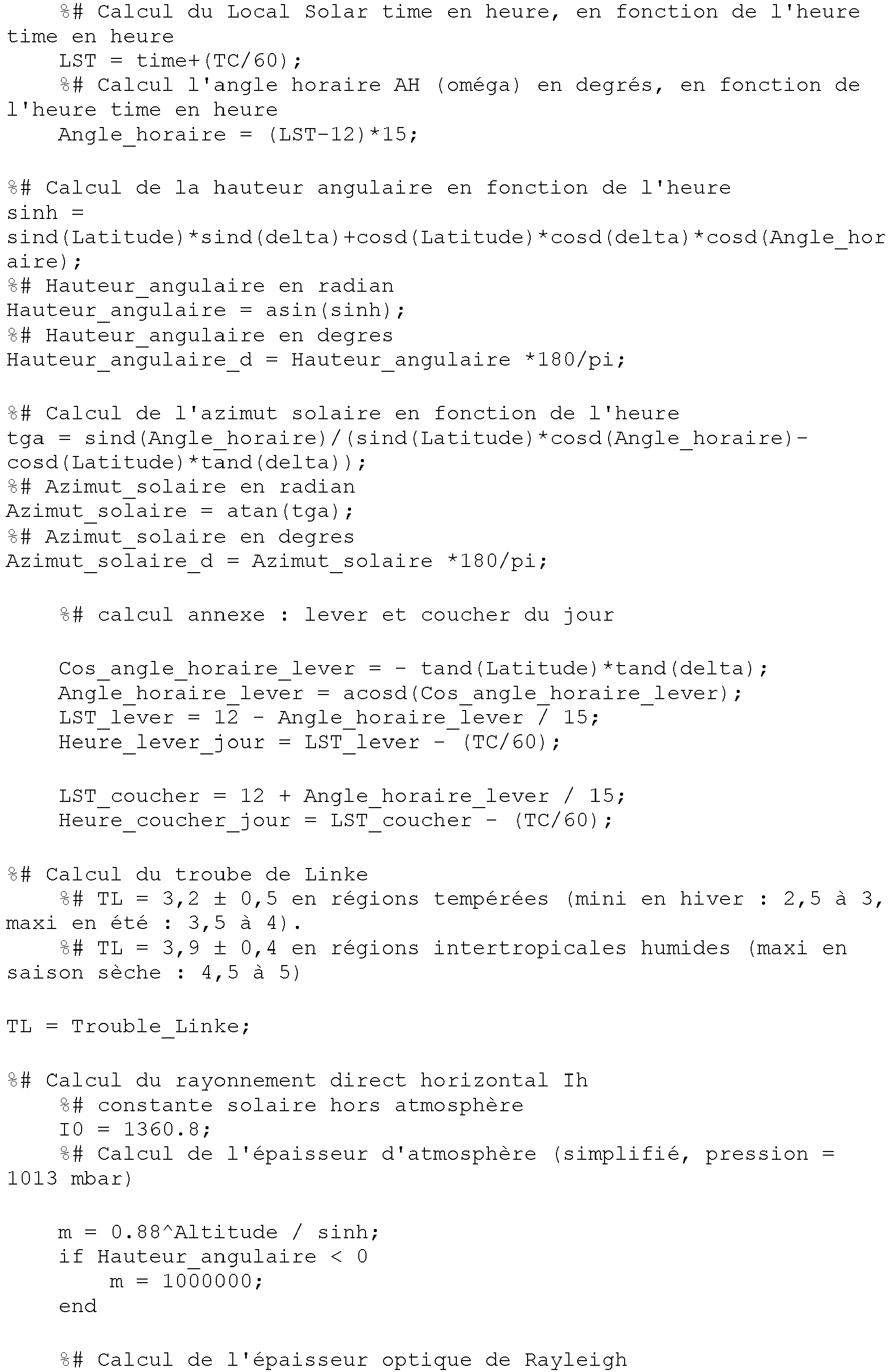


Claims (20)
- A method of shedding load in controlled manner from the outputs of at least one installation (1) for producing electrical energy having at least one source of renewable energy and at least one battery (5), the outputs being classified in at least two distinct levels of importance, the method comprising the following steps for any given day:· on the basis of weather forecasts, predicting the maximum amount of electrical energy that is potentially available as output from the renewable energy source;· on the basis of at least the maximum predicted amount of electrical energy that is potentially available as output from the renewable energy source, deducing an hourly electricity consumption credit for each output level of importance;· subjecting the outputs of a given level of importance to load-shedding when the hourly electricity consumption credit that was allocated to that level has been reached, while giving priority to shedding load from the outputs of lower level of importance.
- A method according to claim 1, wherein the outputs (12, 13, 14) are classified in three distinct levels of importance: a high level of importance, an intermediate level of importance, and a low level of importance.
- A method according to either preceding claim, wherein at least one of the outputs (12, 13, 14) is associated with outlet connections that limit its electricity consumption.
- A method according to claim 3, wherein the output is the output of highest importance in the installation.
- A method according to any preceding claim, wherein the installation (1) can operate in a degraded mode in which the hourly electricity consumption credit is imposed.
- A method according to any preceding claim, wherein the hourly electricity consumption credit for each output level of importance is also deduced as a function of the state of charge of the battery (5).
- A method according to claim 6, wherein a minimum state of charge threshold for the batteries (SoC min), a critical state of charge threshold for the batteries (SoC critical), and a threshold where re-connection is possible given the state of charge of the batteries (SoC re-connection) are set in such a manner that:· if the threshold SoC min is reached, all of the outputs (12, 13, 14) are subjected to load-shedding;· if the threshold SoC critical is reached, the entire installation (1) is switched off.
- A method according to claim 7, wherein the outputs (12, 13, 14) are reactivated only if the threshold SoC re-connection is exceeded.
- A method according to any preceding claim, wherein electricity consumption for each output (12, 13, 14) is estimated for the day, and use is also made of this estimated consumption to deduce the hourly electricity consumption credit for each output level of importance.
- A method according to claim 9, wherein in order to estimate electricity consumption for each output (12, 13, 14) for the day, use is made of at least one stored profile of electricity consumption by said outputs.
- A method according to any preceding claim, wherein an hourly electricity consumption credit that is not consumed in full in any one timeslot is not carried forward to the next timeslot.
- A method according to any preceding claim, including the steps, performed during the day, of comparing the difference between the maximum predicted amount of electrical energy that is potentially available and the amount of electrical energy that is actually produced, and of recalculating accordingly the subsequent hourly electricity consumption credits if the comparison exceeds a predetermined threshold.
- A method according to any preceding claim, wherein in order to predict the maximum amount of electrical energy that is potentially available as output from the renewable energy source, the method relies on data concerning cloudiness, temperature, and UV index.
- A method according to any preceding claim, including the steps of:· measuring the maximum electricity production that is actually available from the renewable energy source;· estimating a maximum forecast electricity production, in particular from weather forecasts;· comparing said maximum forecast electricity production with said maximum electricity production that is actually available in order to forecast the maximum amount of electrical energy that is potentially available as output from the renewable energy source.
- A method according to claim 14, wherein the comparison step is performed by means of a Kalman filter.
- A method according to claim 14 or claim 15, wherein a maximum forecast solar irradiance is estimated in particular from weather forecasts, in order to determine the maximum forecast electricity production.
- A method according to any preceding claim, wherein the installation is a photovoltaic production installation.
- A control member adapted to perform shedding load in controlled manner from the outputs of at least one installation (1) for producing electrical energy having at least one source of renewable energy and at least one battery (5), the outputs being classified in at least two distinct levels of importance, for any given day, the control member comprising:· means configured to predict, on the basis of weather forecasts, the maximum amount of electrical energy that is potentially available as output from the renewable energy source;· means configured to deduced, on the basis of at least the maximum predicted amount of electrical energy that is potentially available as output from the renewable energy source, an hourly electricity consumption credit for each output level of importance;· means configured to subject the outputs of a given level of importance to load-shedding when the hourly electricity consumption credit that was allocated to that level has been reached, while giving priority to shedding load from the outputs of lower level of importance.
- A computer program including instructions for enabling the control member according to claim 18 to perform the steps of the method according to claim 1.
- Storage means storing a computer program including instructions for enabling the control member to perform the method according to any one of claims 1 to 17.
Applications Claiming Priority (1)
| Application Number | Priority Date | Filing Date | Title |
|---|---|---|---|
| FR1915111A FR3105516B1 (en) | 2019-12-20 | 2019-12-20 | Process for shedding the outputs of an electrical energy production installation |
Publications (2)
| Publication Number | Publication Date |
|---|---|
| EP3840158A1 EP3840158A1 (en) | 2021-06-23 |
| EP3840158B1 true EP3840158B1 (en) | 2023-01-25 |
Family
ID=70738635
Family Applications (1)
| Application Number | Title | Priority Date | Filing Date |
|---|---|---|---|
| EP20211626.5A Active EP3840158B1 (en) | 2019-12-20 | 2020-12-03 | Method for load-shedding of outputs from a facility for producing electrical energy |
Country Status (3)
| Country | Link |
|---|---|
| EP (1) | EP3840158B1 (en) |
| CN (1) | CN113013972B (en) |
| FR (1) | FR3105516B1 (en) |
Families Citing this family (2)
| Publication number | Priority date | Publication date | Assignee | Title |
|---|---|---|---|---|
| EP4181349A1 (en) * | 2021-11-15 | 2023-05-17 | STABL Energy GmbH | Solar powered battery system with multilevel converter for traction power networks |
| CN117176079B (en) * | 2023-11-02 | 2024-02-06 | 中科华辰(山东)实业股份有限公司 | Photovoltaic module information management system |
Family Cites Families (7)
| Publication number | Priority date | Publication date | Assignee | Title |
|---|---|---|---|---|
| JP2013529051A (en) * | 2010-05-07 | 2013-07-11 | アドバンスド エナージィ インダストリーズ,インコーポレイテッド | Photovoltaic power generation prediction system and method |
| US8600572B2 (en) * | 2010-05-27 | 2013-12-03 | International Business Machines Corporation | Smarter-grid: method to forecast electric energy production and utilization subject to uncertain environmental variables |
| EP2695270B1 (en) * | 2011-04-08 | 2014-12-31 | SMA Solar Technology AG | Optimized load management |
| CN107005061B (en) * | 2014-08-06 | 2021-07-09 | 新创意有限公司 | Power management system |
| FR3044799B1 (en) * | 2015-12-08 | 2023-01-06 | Electricite De France | METHOD FOR MANAGING A SET OF ELECTRIC ENERGY CONSUMING DEVICES, AND ELECTRIC ENERGY MANAGER MODULE |
| US11271400B2 (en) * | 2015-12-10 | 2022-03-08 | Mitsubishi Electric Corporation | Power control device, operation plan planning method, and recording medium |
| FR3068530B1 (en) * | 2017-06-29 | 2019-08-16 | Sagemcom Energy & Telecom Sas | METHOD FOR DISTRIBUTING AN ELECTRIC ENERGY FROM SOLAR ENERGY TO A PLURALITY OF GROUPS OF AT LEAST ONE ELECTRICAL INSTALLATION |
-
2019
- 2019-12-20 FR FR1915111A patent/FR3105516B1/en active Active
-
2020
- 2020-12-03 EP EP20211626.5A patent/EP3840158B1/en active Active
- 2020-12-18 CN CN202011506153.5A patent/CN113013972B/en active Active
Also Published As
| Publication number | Publication date |
|---|---|
| CN113013972A (en) | 2021-06-22 |
| CN113013972B (en) | 2023-12-01 |
| EP3840158A1 (en) | 2021-06-23 |
| FR3105516A1 (en) | 2021-06-25 |
| FR3105516B1 (en) | 2021-12-17 |
Similar Documents
| Publication | Publication Date | Title |
|---|---|---|
| US9218577B2 (en) | Electric power generation amount estimation device, electric power generation amount estimation system, electric power generation amount estimation method and computer program | |
| EP3840158B1 (en) | Method for load-shedding of outputs from a facility for producing electrical energy | |
| FR2584209A1 (en) | PHOTOVOLTAIC ENERGY CONTROL SYSTEM | |
| FR3060889A1 (en) | METHOD AND DEVICE FOR CHARGING A BATTERY | |
| WO2012059672A2 (en) | Controlling dynamic systems by measuring the no-load voltage of a photovoltaic generator | |
| EP2954381B1 (en) | System and method for enhanced security for solar powered lighting | |
| EP3190681B1 (en) | Method and device for charging a battery | |
| EP2237387A1 (en) | Stromversorgungssystem und Ladungssteuerungsverfahren für elektrochemische Generatoren | |
| AU2022259810A1 (en) | Systems for and methods of positioning solar panels in an array of solar panels with spectrally adjusted irradiance tracking | |
| FR3068530A1 (en) | METHOD FOR DISTRIBUTING AN ELECTRIC ENERGY FROM SOLAR ENERGY TO A PLURALITY OF GROUPS OF AT LEAST ONE ELECTRICAL INSTALLATION | |
| EP3953875A1 (en) | Method for evaluating photovoltaic energy production and evaluation and management unit implementing the method | |
| EP2936423A1 (en) | Management of high-temperature batteries | |
| EP3979163B1 (en) | Optimisation of the energy available in a mini-grid | |
| EP4066340B1 (en) | Resilient micro-network of electrical radiator-type heating appliances | |
| EP2533391B1 (en) | Multi-source management system of electrical generators | |
| WO2017174909A1 (en) | Method for optimizing the electricity consumption of an installation | |
| WO2023222401A1 (en) | Method for forecasting a power produced by at least one photovoltaic panel | |
| EP3671399A1 (en) | Method for determining a preferential minimum power setting, method for controlling a plurality of water heaters and associated device | |
| WO2024002964A1 (en) | Method for managing the energy of an electronic device, device, and corresponding computer program | |
| FR3104843A1 (en) | Micro-grid with a sophisticated balance between consumption and production | |
| WO2021186126A1 (en) | Method and device for controlling an electrical power station, corresponding computer program and power supply facility | |
| FR3140711A1 (en) | Method for estimating a remaining charge time for an electrified motor vehicle | |
| FR2868660A1 (en) | Self-powered lighting equipment e.g. public light, controlling process, involves varying power and duration of lighting based on solar radiation curve of installation location, according to seasons by inputting location coordinates | |
| FR3079072A1 (en) | MAINTENANCE DEVICE FOR BATTERY BENCHES OF A SOLAR POWER PLANT | |
| WO2017103393A1 (en) | Method and device for determining a risk of decrease in insolation |
Legal Events
| Date | Code | Title | Description |
|---|---|---|---|
| PUAI | Public reference made under article 153(3) epc to a published international application that has entered the european phase |
Free format text: ORIGINAL CODE: 0009012 |
|
| STAA | Information on the status of an ep patent application or granted ep patent |
Free format text: STATUS: REQUEST FOR EXAMINATION WAS MADE |
|
| STAA | Information on the status of an ep patent application or granted ep patent |
Free format text: STATUS: EXAMINATION IS IN PROGRESS |
|
| 17P | Request for examination filed |
Effective date: 20201203 |
|
| AK | Designated contracting states |
Kind code of ref document: A1 Designated state(s): AL AT BE BG CH CY CZ DE DK EE ES FI FR GB GR HR HU IE IS IT LI LT LU LV MC MK MT NL NO PL PT RO RS SE SI SK SM TR |
|
| 17Q | First examination report despatched |
Effective date: 20210602 |
|
| RBV | Designated contracting states (corrected) |
Designated state(s): AL AT BE BG CH CY CZ DE DK EE ES FI FR GB GR HR HU IE IS IT LI LT LU LV MC MK MT NL NO PL PT RO RS SE SI SK SM TR |
|
| GRAP | Despatch of communication of intention to grant a patent |
Free format text: ORIGINAL CODE: EPIDOSNIGR1 |
|
| STAA | Information on the status of an ep patent application or granted ep patent |
Free format text: STATUS: GRANT OF PATENT IS INTENDED |
|
| RIC1 | Information provided on ipc code assigned before grant |
Ipc: H02J 1/08 20060101ALN20220620BHEP Ipc: H02J 7/35 20060101ALI20220620BHEP Ipc: H02J 1/14 20060101AFI20220620BHEP |
|
| INTG | Intention to grant announced |
Effective date: 20220704 |
|
| GRAS | Grant fee paid |
Free format text: ORIGINAL CODE: EPIDOSNIGR3 |
|
| GRAA | (expected) grant |
Free format text: ORIGINAL CODE: 0009210 |
|
| STAA | Information on the status of an ep patent application or granted ep patent |
Free format text: STATUS: THE PATENT HAS BEEN GRANTED |
|
| AK | Designated contracting states |
Kind code of ref document: B1 Designated state(s): AL AT BE BG CH CY CZ DE DK EE ES FI FR GB GR HR HU IE IS IT LI LT LU LV MC MK MT NL NO PL PT RO RS SE SI SK SM TR |
|
| REG | Reference to a national code |
Ref country code: GB Ref legal event code: FG4D Free format text: NOT ENGLISH |
|
| REG | Reference to a national code |
Ref country code: CH Ref legal event code: EP |
|
| REG | Reference to a national code |
Ref country code: AT Ref legal event code: REF Ref document number: 1546483 Country of ref document: AT Kind code of ref document: T Effective date: 20230215 Ref country code: IE Ref legal event code: FG4D Free format text: LANGUAGE OF EP DOCUMENT: FRENCH |
|
| REG | Reference to a national code |
Ref country code: DE Ref legal event code: R096 Ref document number: 602020007826 Country of ref document: DE |
|
| REG | Reference to a national code |
Ref country code: LT Ref legal event code: MG9D |
|
| REG | Reference to a national code |
Ref country code: NL Ref legal event code: MP Effective date: 20230125 |
|
| REG | Reference to a national code |
Ref country code: AT Ref legal event code: MK05 Ref document number: 1546483 Country of ref document: AT Kind code of ref document: T Effective date: 20230125 |
|
| PG25 | Lapsed in a contracting state [announced via postgrant information from national office to epo] |
Ref country code: NL Free format text: LAPSE BECAUSE OF FAILURE TO SUBMIT A TRANSLATION OF THE DESCRIPTION OR TO PAY THE FEE WITHIN THE PRESCRIBED TIME-LIMIT Effective date: 20230125 |
|
| PG25 | Lapsed in a contracting state [announced via postgrant information from national office to epo] |
Ref country code: RS Free format text: LAPSE BECAUSE OF FAILURE TO SUBMIT A TRANSLATION OF THE DESCRIPTION OR TO PAY THE FEE WITHIN THE PRESCRIBED TIME-LIMIT Effective date: 20230125 Ref country code: PT Free format text: LAPSE BECAUSE OF FAILURE TO SUBMIT A TRANSLATION OF THE DESCRIPTION OR TO PAY THE FEE WITHIN THE PRESCRIBED TIME-LIMIT Effective date: 20230525 Ref country code: NO Free format text: LAPSE BECAUSE OF FAILURE TO SUBMIT A TRANSLATION OF THE DESCRIPTION OR TO PAY THE FEE WITHIN THE PRESCRIBED TIME-LIMIT Effective date: 20230425 Ref country code: LV Free format text: LAPSE BECAUSE OF FAILURE TO SUBMIT A TRANSLATION OF THE DESCRIPTION OR TO PAY THE FEE WITHIN THE PRESCRIBED TIME-LIMIT Effective date: 20230125 Ref country code: LT Free format text: LAPSE BECAUSE OF FAILURE TO SUBMIT A TRANSLATION OF THE DESCRIPTION OR TO PAY THE FEE WITHIN THE PRESCRIBED TIME-LIMIT Effective date: 20230125 Ref country code: HR Free format text: LAPSE BECAUSE OF FAILURE TO SUBMIT A TRANSLATION OF THE DESCRIPTION OR TO PAY THE FEE WITHIN THE PRESCRIBED TIME-LIMIT Effective date: 20230125 Ref country code: ES Free format text: LAPSE BECAUSE OF FAILURE TO SUBMIT A TRANSLATION OF THE DESCRIPTION OR TO PAY THE FEE WITHIN THE PRESCRIBED TIME-LIMIT Effective date: 20230125 Ref country code: AT Free format text: LAPSE BECAUSE OF FAILURE TO SUBMIT A TRANSLATION OF THE DESCRIPTION OR TO PAY THE FEE WITHIN THE PRESCRIBED TIME-LIMIT Effective date: 20230125 |
|
| PG25 | Lapsed in a contracting state [announced via postgrant information from national office to epo] |
Ref country code: SE Free format text: LAPSE BECAUSE OF FAILURE TO SUBMIT A TRANSLATION OF THE DESCRIPTION OR TO PAY THE FEE WITHIN THE PRESCRIBED TIME-LIMIT Effective date: 20230125 Ref country code: PL Free format text: LAPSE BECAUSE OF FAILURE TO SUBMIT A TRANSLATION OF THE DESCRIPTION OR TO PAY THE FEE WITHIN THE PRESCRIBED TIME-LIMIT Effective date: 20230125 Ref country code: IS Free format text: LAPSE BECAUSE OF FAILURE TO SUBMIT A TRANSLATION OF THE DESCRIPTION OR TO PAY THE FEE WITHIN THE PRESCRIBED TIME-LIMIT Effective date: 20230525 Ref country code: GR Free format text: LAPSE BECAUSE OF FAILURE TO SUBMIT A TRANSLATION OF THE DESCRIPTION OR TO PAY THE FEE WITHIN THE PRESCRIBED TIME-LIMIT Effective date: 20230426 Ref country code: FI Free format text: LAPSE BECAUSE OF FAILURE TO SUBMIT A TRANSLATION OF THE DESCRIPTION OR TO PAY THE FEE WITHIN THE PRESCRIBED TIME-LIMIT Effective date: 20230125 |
|
| REG | Reference to a national code |
Ref country code: DE Ref legal event code: R097 Ref document number: 602020007826 Country of ref document: DE |
|
| PG25 | Lapsed in a contracting state [announced via postgrant information from national office to epo] |
Ref country code: SM Free format text: LAPSE BECAUSE OF FAILURE TO SUBMIT A TRANSLATION OF THE DESCRIPTION OR TO PAY THE FEE WITHIN THE PRESCRIBED TIME-LIMIT Effective date: 20230125 Ref country code: RO Free format text: LAPSE BECAUSE OF FAILURE TO SUBMIT A TRANSLATION OF THE DESCRIPTION OR TO PAY THE FEE WITHIN THE PRESCRIBED TIME-LIMIT Effective date: 20230125 Ref country code: EE Free format text: LAPSE BECAUSE OF FAILURE TO SUBMIT A TRANSLATION OF THE DESCRIPTION OR TO PAY THE FEE WITHIN THE PRESCRIBED TIME-LIMIT Effective date: 20230125 Ref country code: DK Free format text: LAPSE BECAUSE OF FAILURE TO SUBMIT A TRANSLATION OF THE DESCRIPTION OR TO PAY THE FEE WITHIN THE PRESCRIBED TIME-LIMIT Effective date: 20230125 Ref country code: CZ Free format text: LAPSE BECAUSE OF FAILURE TO SUBMIT A TRANSLATION OF THE DESCRIPTION OR TO PAY THE FEE WITHIN THE PRESCRIBED TIME-LIMIT Effective date: 20230125 |
|
| PG25 | Lapsed in a contracting state [announced via postgrant information from national office to epo] |
Ref country code: SK Free format text: LAPSE BECAUSE OF FAILURE TO SUBMIT A TRANSLATION OF THE DESCRIPTION OR TO PAY THE FEE WITHIN THE PRESCRIBED TIME-LIMIT Effective date: 20230125 |
|
| PLBE | No opposition filed within time limit |
Free format text: ORIGINAL CODE: 0009261 |
|
| STAA | Information on the status of an ep patent application or granted ep patent |
Free format text: STATUS: NO OPPOSITION FILED WITHIN TIME LIMIT |
|
| 26N | No opposition filed |
Effective date: 20231026 |
|
| PG25 | Lapsed in a contracting state [announced via postgrant information from national office to epo] |
Ref country code: SI Free format text: LAPSE BECAUSE OF FAILURE TO SUBMIT A TRANSLATION OF THE DESCRIPTION OR TO PAY THE FEE WITHIN THE PRESCRIBED TIME-LIMIT Effective date: 20230125 |
|
| PGFP | Annual fee paid to national office [announced via postgrant information from national office to epo] |
Ref country code: FR Payment date: 20231122 Year of fee payment: 4 Ref country code: DE Payment date: 20231121 Year of fee payment: 4 |