EP3840138A1 - Dwdm intra-cavity laser device - Google Patents
Dwdm intra-cavity laser device Download PDFInfo
- Publication number
- EP3840138A1 EP3840138A1 EP19217129.6A EP19217129A EP3840138A1 EP 3840138 A1 EP3840138 A1 EP 3840138A1 EP 19217129 A EP19217129 A EP 19217129A EP 3840138 A1 EP3840138 A1 EP 3840138A1
- Authority
- EP
- European Patent Office
- Prior art keywords
- tunable
- optical
- laser device
- dwdm
- ring resonator
- Prior art date
- Legal status (The legal status is an assumption and is not a legal conclusion. Google has not performed a legal analysis and makes no representation as to the accuracy of the status listed.)
- Withdrawn
Links
Images



Classifications
-
- H—ELECTRICITY
- H01—ELECTRIC ELEMENTS
- H01S—DEVICES USING THE PROCESS OF LIGHT AMPLIFICATION BY STIMULATED EMISSION OF RADIATION [LASER] TO AMPLIFY OR GENERATE LIGHT; DEVICES USING STIMULATED EMISSION OF ELECTROMAGNETIC RADIATION IN WAVE RANGES OTHER THAN OPTICAL
- H01S5/00—Semiconductor lasers
- H01S5/06—Arrangements for controlling the laser output parameters, e.g. by operating on the active medium
- H01S5/068—Stabilisation of laser output parameters
- H01S5/06821—Stabilising other output parameters than intensity or frequency, e.g. phase, polarisation or far-fields
-
- H—ELECTRICITY
- H01—ELECTRIC ELEMENTS
- H01S—DEVICES USING THE PROCESS OF LIGHT AMPLIFICATION BY STIMULATED EMISSION OF RADIATION [LASER] TO AMPLIFY OR GENERATE LIGHT; DEVICES USING STIMULATED EMISSION OF ELECTROMAGNETIC RADIATION IN WAVE RANGES OTHER THAN OPTICAL
- H01S5/00—Semiconductor lasers
- H01S5/06—Arrangements for controlling the laser output parameters, e.g. by operating on the active medium
- H01S5/0607—Arrangements for controlling the laser output parameters, e.g. by operating on the active medium by varying physical parameters other than the potential of the electrodes, e.g. by an electric or magnetic field, mechanical deformation, pressure, light, temperature
- H01S5/0612—Arrangements for controlling the laser output parameters, e.g. by operating on the active medium by varying physical parameters other than the potential of the electrodes, e.g. by an electric or magnetic field, mechanical deformation, pressure, light, temperature controlled by temperature
-
- H—ELECTRICITY
- H01—ELECTRIC ELEMENTS
- H01S—DEVICES USING THE PROCESS OF LIGHT AMPLIFICATION BY STIMULATED EMISSION OF RADIATION [LASER] TO AMPLIFY OR GENERATE LIGHT; DEVICES USING STIMULATED EMISSION OF ELECTROMAGNETIC RADIATION IN WAVE RANGES OTHER THAN OPTICAL
- H01S5/00—Semiconductor lasers
- H01S5/06—Arrangements for controlling the laser output parameters, e.g. by operating on the active medium
- H01S5/062—Arrangements for controlling the laser output parameters, e.g. by operating on the active medium by varying the potential of the electrodes
- H01S5/0625—Arrangements for controlling the laser output parameters, e.g. by operating on the active medium by varying the potential of the electrodes in multi-section lasers
- H01S5/06255—Controlling the frequency of the radiation
- H01S5/06256—Controlling the frequency of the radiation with DBR-structure
-
- H—ELECTRICITY
- H01—ELECTRIC ELEMENTS
- H01S—DEVICES USING THE PROCESS OF LIGHT AMPLIFICATION BY STIMULATED EMISSION OF RADIATION [LASER] TO AMPLIFY OR GENERATE LIGHT; DEVICES USING STIMULATED EMISSION OF ELECTROMAGNETIC RADIATION IN WAVE RANGES OTHER THAN OPTICAL
- H01S5/00—Semiconductor lasers
- H01S5/10—Construction or shape of the optical resonator, e.g. extended or external cavity, coupled cavities, bent-guide, varying width, thickness or composition of the active region
- H01S5/1028—Coupling to elements in the cavity, e.g. coupling to waveguides adjacent the active region, e.g. forward coupled [DFC] structures
- H01S5/1032—Coupling to elements comprising an optical axis that is not aligned with the optical axis of the active region
-
- H—ELECTRICITY
- H01—ELECTRIC ELEMENTS
- H01S—DEVICES USING THE PROCESS OF LIGHT AMPLIFICATION BY STIMULATED EMISSION OF RADIATION [LASER] TO AMPLIFY OR GENERATE LIGHT; DEVICES USING STIMULATED EMISSION OF ELECTROMAGNETIC RADIATION IN WAVE RANGES OTHER THAN OPTICAL
- H01S5/00—Semiconductor lasers
- H01S5/10—Construction or shape of the optical resonator, e.g. extended or external cavity, coupled cavities, bent-guide, varying width, thickness or composition of the active region
- H01S5/12—Construction or shape of the optical resonator, e.g. extended or external cavity, coupled cavities, bent-guide, varying width, thickness or composition of the active region the resonator having a periodic structure, e.g. in distributed feedback [DFB] lasers
- H01S5/125—Distributed Bragg reflector [DBR] lasers
-
- H—ELECTRICITY
- H01—ELECTRIC ELEMENTS
- H01S—DEVICES USING THE PROCESS OF LIGHT AMPLIFICATION BY STIMULATED EMISSION OF RADIATION [LASER] TO AMPLIFY OR GENERATE LIGHT; DEVICES USING STIMULATED EMISSION OF ELECTROMAGNETIC RADIATION IN WAVE RANGES OTHER THAN OPTICAL
- H01S5/00—Semiconductor lasers
- H01S5/10—Construction or shape of the optical resonator, e.g. extended or external cavity, coupled cavities, bent-guide, varying width, thickness or composition of the active region
- H01S5/14—External cavity lasers
- H01S5/141—External cavity lasers using a wavelength selective device, e.g. a grating or etalon
- H01S5/142—External cavity lasers using a wavelength selective device, e.g. a grating or etalon which comprises an additional resonator
Definitions
- Embodiments of the present disclosure relate to a Dense Wavelength Division Multiplex (DWDM) intra-cavity laser device, and in particular to a DWDM intra-cavity laser device comprising DWDM-filter with an intra-cavity ring resonator arranged between two gratings, wherein said DWDM intra-cavity laser device is tunable in a discrete manner such that the free spectral range of the ring resonator matches a predetermined fixed wavelength spacing grid, for example the ITU-grid (ITU: International Telecommunication Union).
- ITU-grid International Telecommunication Union
- Tunable lasers are preferred over fixed wavelength lasers.
- Tunable lasers may have an advantage to realize cost effectiveness by realizing flexible and sliceable channels compared to fixed wavelength lasers.
- Tunable lasers may provide for wavelength tuning over the C-band and narrow linewidth for low phase noise.
- Adaptation to the ITU channels may be one of several interests regarding tunable lasers.
- the wavelength of tunable lasers have to be exactly tuned to an equal wavelength grid, the so-called ITU grid having a frequency grid spacing of, e.g. 50 GHz, 100 GHz or 200 GHz. Therefore a tight control and fine tuning of the wavelength is desired.
- external Fabry-Perot (FP) etalons are generally used as a filter with a free spectral range (FSR) corresponding to the ITU grid. After passing through the filter, a photo detector monitors the signal to find the accurate wavelength. [1-2, 1-3].
- FP Fabry-Perot
- FSR free spectral range
- Coupled Cavity Lasers are used where the cavity length has been optimized to match the 100 GHz.
- These lasers consist of two cavities coupled with one reflector. One cavity length is matched to the 100 GHz, therefore a control of the second cavity generates wavelength tuning automatically matched to the ITU 100 GHz grid [1-4].
- CCLs Coupled Cavity Lasers
- Wide wavelength tuning is commonly realized by using the Vernier effect, which utilizes two comb-like filters to select different wavelengths with extended tuning range, which covers the C-band and could potentially also cover e.g. C + L band.
- filters e.g. a Bragg grating based on either one of sampled gratings (SG), super-structure gratings (SSG) and ring resonators (RR) may be used.
- SG-DBR based lasers are reported in [1-5] over the full C-band with a lower linewidth of 100 kHz. This laser, however, contains an additional filter to decrease a value of side mode suppression (SMSR). SSG-DBR lasers may offer a tuning range of 40 nm but linewidth is 400 kHz [1-9].
- ring resonators Because of the compact footprint so far silicon related materials based RRs are preferred. Narrow bendings with small radius are possible because of their high index contrast, e.g. silicon, silicon nitride and silicon oxide [1-10].
- these materials have an indirect bandgap only and thus require a hybrid integration with III-V active sections as a light source. This brings about extra fabrication processes for a wafer bonding or butt coupling and thus increased fabrication costs.
- reference [1-11] proposes a Fabry-Perot (FP) laser with a double ring resonator based on InGaAsP/InP, which covers 24 nm tuning with side mode suppression of over 40 dB.
- the RRs are optimized to cover a wide tuning range, however it requires a tight radius of the RRs below 15 ⁇ m.
- the small radius generates leakage of light resulting in waveguide bending losses higher than 10 dB/cm, which broadens the linewidth of the lasers.
- RRs and gratings may be used for the Vernier effect but these devices still suffer from the high waveguide bending losses in III-V based materials, as described above.
- RRs may be used as a wavelength filter.
- Devices with such large RRs and with three asymmetric Mach-Zehnder interferometer (AMZI) show 74.3 nm tuning range with a linewidth of 363 kHz.
- AMZI Mach-Zehnder interferometer
- this device suffers from a very large footprint of 3.65 x 0.9 mm 2 and the obtained linewidth is still too large for coherent modules, e.g. QPSK and 16-QAM [1-14].
- Three section DBR lasers with an intra-cavity RR show a narrow linewidth of 63 kHz. They have been optimized for single mode operation by controlling the free spectral range to match the full-width half maximum of the DBR reflection. However, the wavelength is fixed and, thus, not tunable [1-15]. Furthermore in reference [1-15] the laser output suffers from a high propagation loss in the front grating.
- gratings may be preferred due to their maturity of processing, e.g. III-V integration.
- Ring resonators instead may provide a high Q-factor.
- silicon based RRs have a desired Q-factor.
- they have an indirect bandgap only.
- hybrid integration with III-V is necessary.
- a wide tuning range requires a small radius of the ring resonator.
- a small radius leads to high waveguide bending losses which broaden the linewidth.
- ring resonators may have a trade-off between reducing the radius to provide a wide tuning range but with low bending losses providing a narrow line width.
- Very high Q ring resonators of a large radius also extend tuning range but it may require more than three coupled ring resonators with extremely low loss waveguide.
- the invention provides a proper solution by means of the tunable DWDM intra-cavity laser device according to claim 1.
- the inventive tunable DWDM intra-cavity laser device comprises, inter alia, a first optical wave guide comprising a first optical grating section and a second optical wave guide comprising a second optical grating section.
- the tunable DWDM laser may further comprise a phase section and an active gain section being separated from the second optical grating section, which may characterize a DBR-laser (DBR: Distributed Bragg Reflector) and differentiate the same from a DFB-laser (DFB: Distributed Feedback).
- DBR Distributed Bragg Reflector
- DFB Distributed Feedback
- the inventive tunable DWDM laser may further comprise a DWDM-filter comprising an intra-cavity ring resonator located between the first optical wave guide and the second optical wave guide for coupling optical waves between the first and second optical wave guides.
- the tunable laser device is tunable in a discrete fashion, wherein the tuning may depend on a length of the ring resonator.
- the length of the ring resonator is selected such that the free spectral range (FSR) of the ring resonator exactly matches a predetermined fixed wavelength spacing grid.
- the ring resonator may be matched to said predetermined fixed wavelength spacing grid by having an FSR which allows the ring resonator to exactly "jump" into at least one grid point of the predetermined grid.
- a wavelength/frequency grid is a table of all the central frequencies (and corresponding wavelengths) of channels allowed in a communication system.
- At least one of the first optical grating section, the second optical grating section and the phase section may be tunable for fine-tuning the optical wavelength so as to switch, in discrete fixed wavelength-spacing-steps, between two or more channels inside the predetermined fixed wavelength spacing grid to which the ring resonator is matched.
- the predetermined fixed wavelength spacing grid may, for instance, correspond to the ITU-grid.
- the invention may provide an innovative tunable laser concept using an intra cavity RR that allows for an automatic matching to the ITU-grid.
- This innovative concept may comprise a 4-section DBR laser for the Vernier effect, such as SG or SSG DBR lasers, but it additionally offers a narrow optical linewidth.
- Said ITU-grid may be the most common frequency grid used for fiber-optic communication.
- the ITU-grid is used for channel spacing in Dense Wavelength Division Multiplexing (DWDM) at wavelengths around 1550 nm and is defined by ITU-T G.694.1.
- DWDM Dense Wavelength Division Multiplexing
- the ITU-grid is defined relative to 193.1 THz and extends from 191.7 THz to 196.1 THz with 100 GHz spacing. While defined in frequency, the grid is often expressed in terms of wavelength, in which case it covers the wavelength range of 1528.77 nm to 1563.86 nm with approximately a 0.8 nm channel spacing. For practical purposes, the ITU-grid has meanwhile been extended to cover 186 THz to 201 THz and subdivided to provide 50 GHz (0.4 nm), 25 GHz (0.2 nm) and even 12.5 GHz (0.1 nm) spaced grids.
- the ring resonator may comprise a length in the range between 416 ⁇ m and 3330 ⁇ m corresponding to a radius between 66 ⁇ m to 530 ⁇ m.
- the ring resonator may further provide for a narrow optical line width of the output light below 200 kHz, or below 150 kHz, or even below 100 kHz.
- the ring resonator may provide a tuning range of at least 20 nm, or of at least 30 nm or of at least 40 nm and above.
- the herein described innovative concept may provide a discrete automatic tuning to the ITU-grid, while nowadays conventional tunable lasers require a tight and complicated control to exactly match the grid.
- the innovative integrated DWDM filter which is realized with a ring resonator, may allow to filter the signal for matching the ITU-grid inherently.
- the ring resonator may provide a longer effective length of the cavity with a high Q-factor to improve the linewidth and preserve the tuning ability of the laser.
- Method steps which are depicted by means of a block diagram and which are described with reference to said block diagram may also be executed in an order different from the depicted and/or described order. Furthermore, method steps concerning a particular feature of a device may be replaceable with said feature of said device, and the other way around.
- Figure 3 shows a tunable DBR laser according to the prior art.
- Said Figure shows a conventional InP based 4-section DBR tunable laser 300 with an external etalon filter 306.
- the prior art laser 300 is composed of a gain 303, a phase 304, a rear DBR section 311 and a front DBR section 312 coupled to an output 305.
- the prior art laser 300 contains an external ITU grid FP etalon filter 306 with a photo detector 307 to detect the signal.
- bulky modules are required to implement the external FP etalon filter.
- PIC photonic integrated circuits
- reference [2-1] a quarter lambda DBR is used as a wavelength filter.
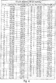
- FIG. 4 shows a table of an ITU grid with 100 GHz spacing.
- the ITU grid varies around a basis wavelength of 1555.75 nm with value ranges of wavelengths above and below 1555.75 nm.
- the ITU grid may comprise 73 different channels ranging from 190.100 GHz to 197.300 GHz with a frequency spacing of 100 GHz between each channel, which may correspond to a wavelength spacing of approximately 0.8 nm. Accordingly, this depicted ITU grid corresponds to a fixed wavelength spacing grid having a fixed wavelength spacing of 0.8 nm.
- the predetermined fixed wavelength spacing grid may also be expressed in terms of frequency spacing, which would then correspond to a predetermined fixed frequency spacing grid. In this example shown in Figure 4 , the depicted ITU grid would correspond to a predetermined fixed frequency spacing grid having a fixed frequency spacing of 100 GHz.
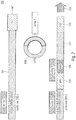
- FIG. 1 now shows an embodiment of a tunable DWDM intra-cavity laser device 100 according to the present invention which is configured to automatically tune into such a predetermined fixed wavelength spacing grid, wherein tuning may be accomplished in a discrete manner, i.e. in discrete steps.
- the tunable DWDM intra-cavity laser device 100 may comprise a first optical wave guide 101 comprising a first optical grating section 111 and a second optical wave guide 102 comprising a second optical grating section 112.
- the tunable DWDM intra-cavity laser device 100 may further comprise an active gain section 103 that is spatially separated from the second optical grating section 112 corresponding to a DBR-laser.
- the tunable DWDM intra-cavity laser device 100 may further comprise a phase section 104. Light may be coupled out from the second optical wave guide 102 at a light output section of the laser cavity, as indicated by arrow 105. So far, the tunable DWDM intra-cavity laser device 100 may comprise the structure of a 4-section DBR laser.
- the first optical grating section 111 may be arranged in the first optical wave guide 101.
- the second optical grating section 112 may be arranged in the second optical wave guide 102.
- the gain section 103 and the phase section 104 may also be arranged in the second optical wave guide 102.
- the optical wave guides 101, 102 may be passive, i.e. without an active layer.
- the gain section 103 may, however, comprise an active layer.
- the tunable DWDM intra-cavity laser device 100 may optionally comprise an intra-cavity photo detector 107 that may be arranged in the first optical wave guide 101. Further optionally, the tunable DWDM intra-cavity laser device 100 may comprise a semiconductor optical amplifier (SOA) at the light output section 105 of the cavity.
- SOA semiconductor optical amplifier
- the tunable DWDM intra-cavity laser device 100 may further comprise a DWDM-filter comprising an intra-cavity ring resonator 106 being located between the first optical wave guide 101 and the second optical wave guide 102 for coupling optical waves between the first and second optical wave guides 101, 102.
- Coupling components between the optical waveguides 101, 102 and the ring resonator 106 may be at least one of directional couplers or MMIs.
- MMIs directional couplers
- 1x2 MMI couplers have the advantage of a compact footprint but in this case no photo detectors may be integrated in the tunable laser.
- the tunable DWDM intra-cavity laser device 100 may comprise the structure of a 4-section DBR laser additionally comprising a ring resonator 106.
- the tunable laser device 100 may be tunable in a discrete fashion. Said discrete tuning may depend on the length (or radius) of the ring resonator 106, wherein the length is selected such that the free spectral range (FSR) of the ring resonator 106 matches a predetermined fixed wavelength spacing grid.
- Said predetermined fixed wavelength spacing grid may correspond to an ITU grid with a fixed wavelength spacing of at least one of 12.5 GHz, 25 GHz, 50 GHz, 100 GHz or 200 GHz.
- the ring resonator 106 may comprise a length in the range between 416 ⁇ m and 3330 ⁇ m.
- the length of the ring resonator 106 may correspond to 3330 ⁇ m to be matched to the ITU grid with 25 GHz channel spacing, or the length of the ring resonator 106 may correspond to 1665 ⁇ m to be matched to the ITU grid with 50 GHz channel spacing, or the length of the ring resonator 106 may correspond to 832 ⁇ m to be matched to the ITU grid with 100 GHz channel spacing, or the length of the ring resonator 106 may correspond to 416 ⁇ m to be matched to the ITU grid with 200 GHz channel spacing.
- the innovative tunable DWDM intra-cavity laser device 100 may provide for an automatic matching of the wavelength to the ITU grid.
- the length of the ring resonator 106 may be optimized so that the FSR of the ring resonator 106 is equal to the wavelength spacing of the ITU grid. Therefore, the ring resonator 106 may act as a dedicated DWDM filter complying with the ITU standard.
- the wavelength tuning works like in common tunable lasers with the decisive difference that the tuning is discrete because of the FSR of the ring resonator 106, which acts as the DWDM filter.
- the wavelength tuning "jumps" by discrete steps to the ITU grid owing to the intra DWDM filter provided by the particularly matched ring resonator 106.
- FIG 2 shows a further embodiment of a tunable DWDM intra-cavity laser device 100 according to the present invention.
- This DWDM laser device 100 may substantially correspond to the first embodiment described above with reference to Figure 1 .
- elements and features having the same or similar function are provided with the same reference numerals.
- the first optical grating section 111 may comprise a comb-like optical grating and/or the second optical grating section 112 may comprise a comb-like optical grating.
- at least one of the first optical grating section 111 and the second optical grating section 112 may comprise a sampled grating (SG) or a super-structure grating (SSG).
- the optical grating sections 111, 112 may comprise at least one of normal DBR gratings, sampled gratings (SG), or super-structure gratings (SSG) or variations thereof.
- the optical grating sections 111, 112 may be tuned by thermal heating and/or by means of applied voltage, see boxes labeled with "Tuning 1" and “Tuning 2" in Figures 1 and 2 .
- the ring resonator 106 itself may be matched to at least one predetermined fixed wavelength grid, which may also be referred to as grid-setting, by selecting the length of the ring resonator 106 so that its FSR corresponds to the respective grid, see box labeled with "Tuning 4" in Figures 1 and 2 .
- the DWDM intra-cavity laser device 100 may be coarsely tuned in that the ring resonator 106 may be matched to at least one predetermined fixed wavelength spacing grid, e.g. to an ITU-grid with 100 GHz channel spacing.
- the DWDM intra-cavity laser device 100 may also be fine-tuned by means of at least one of the first optical grating section 111, the second optical grating section 112 and the phase section 104 in order to switch between different channels inside the grid.
- at least one of the first optical grating section 111, the second optical grating section 112 and the phase section 104 may be tunable (separately or in combination with each other) for fine-tuning the optical wavelength so as to switch, in discrete fixed wavelength-spacing-steps, between two or more channels inside the predetermined fixed wavelength spacing grid to which the ring resonator 106 is matched.
- the first optical grating section 111 and the second optical grating section 112 may be mutually tunable for providing a Vernier effect for switching between two or more channels inside the predetermined fixed wavelength spacing grid.
- the ring resonator 106 itself may be used for coarse tuning (grid-setting). However, as mentioned above, this tuning possibility of the ring resonator 106 may not be used for the above described fine-tuning of the optical wavelength so as to switch between two or more channels inside the predetermined fixed wavelength spacing grid. Since the ring resonator 106 itself may not be needed for the wavelength fine-tuning, the ring resonator 106 may not be involved in the fine-tuning of the optical wavelength and/or in providing the Vernier effect.
- the ring resonator 106 may comprise a further tuning option that may be used to fine-tune the ring resonator 106 itself, wherein said further tuning option may be applied to the ring resonator 106 for compensating for fabrication tolerances to exactly match the predetermined grid, e.g. the ITU grid.
- the ring resonator 106 may be fine-tuned its free spectral range (FSR) so as to compensate for fabrication tolerances and to precisely match the predetermined fixed wavelength spacing grid. Because of the long cavity length of, e.g. more than 416 ⁇ m, a fabrication tolerance of ⁇ 100 nm may result in a small change of the FSR only.
- the expected FSR difference between target and real value may be below 1% and may be compensated by tuning the ring resonator 106.
- the output power may be coupled from the ring resonator 106, not from a front DBR as in common DBR type lasers. Accordingly, the light output section 105 of the DWDM intra cavity laser device 100 may be grating-less.
- the second optical grating section 112 may be provided as a rear grating arranged opposite the light-output section 105, wherein said rear grating 112 may be configured to reflect the optical waves inside the cavity.
- output power may not be coupled out from the rear DBR grating 112 but it may only be reflected by the rear DBR grating 112 and be coupled out from the ring resonator 106 instead.
- the omittance of a front grating helps to avoid power losses which may otherwise occur during the propagation through prior art front gratings.
- the additional booster SOA amplifier 108 may further increase the output power of the DWDM intra cavity laser device 100.
- a low loss propagation in the ring resonator 106 is feasible because the radius of the ring resonator 106 for 100 GHz or 200 GHz FSR is large enough to achieve a desired low loss propagation. This is due to the fact that in the herein described innovative concept the ring resonator 106 acts like a filter for narrow wavelength (e.g. 0.8 nm for 100 GHz), whereas the prior art ring resonators used for the Vernier effect requires longer FSRs of more than a few nanometers.
- the ring resonator 106 of the herein described principle may provide for a narrow optical line width of the output light below 200 kHz.
- the herein described ring resonator 106 may increase the effective length of the cavity and may thus improve the linewidth.
- the high Q factor of ring resonator 106 with the Lorentzian filtering in combination with the DBRs 111, 112 may provide a strong mode selection for single mode operation.
- the prior art may suggest to use FP etalon filters for the grid-setting.
- bulky modules are required to implement the external FP etalon filter.
- an external-cavity Fabry-Perot etalon filter may be explicitly omitted.
- the DWDM intra cavity laser device 100 does not comprise a bulky external-cavity Fabry-Perot etalon filter.
- FIGS 5A and 5B show a structure of the references [2-1] and [2-3], respectively. They show a three-section DBR laser with a passive ring and a tunable ring resonator ( Figure 5A ) and additionally with integrated photo detectors ( Figure 5B ).
- the two gratings 511, 512 are purely passive sections, which means that the reflection is fixed.
- the ring resonator 506 is used to shift the filter wavelength.
- the tuning range amounts to 8 nm only because the Vernier effect cannot be used here.
- the photo detectors 507 are integrated to monitor wavelength and power of the laser and the tuning mechanism is identical to reference [2-1]. Moreover, the purpose of the laser is to achieve an athermal laser. Both of the lasers are based on silicon photonics with hybrid III-V integration.
- the herein described innovative concept may apply standard monolithic InP processing for laser fabrication. No hybrid processes as e.g. wafer bonding, but joint coupling of external light sources are needed here.
- the herein described innovative concept may provide a widely tunable laser device 100 integrated with an internal DWDM filter 106 for automatic matching to the ITU grid and with a narrow linewidth.
- the laser device 100 may basically correspond to a 4-section DBR laser with an additional intra cavity ring resonator 106, and which may be controlled by 3-sections only.
- the herein described innovative tunable laser device 100 may provide simple tuning and excellent performance. Possible industrial applications may be given in any ITU grid based Optical Network, in particular in Passive Optical Networks.
- aspects have been described in the context of an apparatus, it is clear that these aspects also represent a description of the corresponding method, where a block or device corresponds to a method step or a feature of a method step. Analogously, aspects described in the context of a method step also represent a description of a corresponding block or item or feature of a corresponding apparatus.
Landscapes
- Physics & Mathematics (AREA)
- Condensed Matter Physics & Semiconductors (AREA)
- General Physics & Mathematics (AREA)
- Electromagnetism (AREA)
- Optics & Photonics (AREA)
- Lasers (AREA)
- Semiconductor Lasers (AREA)
Abstract
The present invention concerns a tunable Dense Wavelength Division Multiplex (DWDM) intra cavity laser device (100) comprising a first optical wave guide (101) comprising a first optical grating section (111), a second optical wave guide (102) comprising a second optical grating section (112), an active gain section (103) spatially separated from the second optical grating section (112) and a phase section (104), and a DWDM-filter comprising an intra-cavity ring resonator (106) located between the first optical wave guide (101) and the second optical wave guide (102) for coupling optical waves between the first and second optical wave guides (101, 102). The tunable laser device (100) is tunable in a discrete manner depending on a length of the ring resonator (106) that is selected such that the free spectral range of the ring resonator (106) matches a predetermined fixed wavelength spacing grid.
Description
- Embodiments of the present disclosure relate to a Dense Wavelength Division Multiplex (DWDM) intra-cavity laser device, and in particular to a DWDM intra-cavity laser device comprising DWDM-filter with an intra-cavity ring resonator arranged between two gratings, wherein said DWDM intra-cavity laser device is tunable in a discrete manner such that the free spectral range of the ring resonator matches a predetermined fixed wavelength spacing grid, for example the ITU-grid (ITU: International Telecommunication Union).
- For coherent dense wavelength-division multiplexing (DWDM), tunable lasers are preferred over fixed wavelength lasers. Tunable lasers may have an advantage to realize cost effectiveness by realizing flexible and sliceable channels compared to fixed wavelength lasers. Tunable lasers may provide for wavelength tuning over the C-band and narrow linewidth for low phase noise. [1-1]
- Adaptation to the ITU channels may be one of several interests regarding tunable lasers. For DWDM applications the wavelength of tunable lasers have to be exactly tuned to an equal wavelength grid, the so-called ITU grid having a frequency grid spacing of, e.g. 50 GHz, 100 GHz or 200 GHz. Therefore a tight control and fine tuning of the wavelength is desired. To match the ITU grid, external Fabry-Perot (FP) etalons are generally used as a filter with a free spectral range (FSR) corresponding to the ITU grid. After passing through the filter, a photo detector monitors the signal to find the accurate wavelength. [1-2, 1-3]. However, most of the published approaches are based on fiber or free space optics. So bulky modules and thus expensive packaging is needed.
- In some approaches, Coupled Cavity Lasers (CCLs) are used where the cavity length has been optimized to match the 100 GHz. These lasers consist of two cavities coupled with one reflector. One cavity length is matched to the 100 GHz, therefore a control of the second cavity generates wavelength tuning automatically matched to the ITU 100 GHz grid [1-4]. However, because of the long active cavity and thus high optical losses in said CCLs, no narrow linewidth values can be expected here.
- Wide wavelength tuning is commonly realized by using the Vernier effect, which utilizes two comb-like filters to select different wavelengths with extended tuning range, which covers the C-band and could potentially also cover e.g. C + L band. For the filters, e.g. a Bragg grating based on either one of sampled gratings (SG), super-structure gratings (SSG) and ring resonators (RR) may be used.
- Most of commercially available widely tunable lasers are using SG or SSG based tunable lasers because of the maturity of the technology and the advantage of monolithic III-V integration [1-5, 1-6, 1-7, 1-8]. However, there is a limitation of a linewidth improvement to sub-kHz with III-V material because of a difficulty of realizing the gratings with an high quality (Q) factor. SG-DBR based lasers are reported in [1-5] over the full C-band with a lower linewidth of 100 kHz. This laser, however, contains an additional filter to decrease a value of side mode suppression (SMSR). SSG-DBR lasers may offer a tuning range of 40 nm but linewidth is 400 kHz [1-9].
- Recently, there has been a great interest in ring resonators (RRs) because of their long effective length with low propagation loss, allowing for a high Q factor filter in order to achieve a narrow linewidth. Because of the compact footprint so far silicon related materials based RRs are preferred. Narrow bendings with small radius are possible because of their high index contrast, e.g. silicon, silicon nitride and silicon oxide [1-10]. However, these materials have an indirect bandgap only and thus require a hybrid integration with III-V active sections as a light source. This brings about extra fabrication processes for a wafer bonding or butt coupling and thus increased fabrication costs.
- Different variants of RR-based III-V lasers have been investigated in the past but the resulting performance usually was worse than with silicon based RRs because of the relatively higher propagation loss.
- As an example, reference [1-11] proposes a Fabry-Perot (FP) laser with a double ring resonator based on InGaAsP/InP, which covers 24 nm tuning with side mode suppression of over 40 dB. For the Vernier effect, the RRs are optimized to cover a wide tuning range, however it requires a tight radius of the RRs below 15 µm. However, as a drawback, the small radius generates leakage of light resulting in waveguide bending losses higher than 10 dB/cm, which broadens the linewidth of the lasers.
- In [1-12] and [1-13] RRs and gratings may be used for the Vernier effect but these devices still suffer from the high waveguide bending losses in III-V based materials, as described above.
- To improve the loss issue, larger RRs may be used as a wavelength filter. Devices with such large RRs and with three asymmetric Mach-Zehnder interferometer (AMZI) show 74.3 nm tuning range with a linewidth of 363 kHz. However, this device suffers from a very large footprint of 3.65 x 0.9 mm2 and the obtained linewidth is still too large for coherent modules, e.g. QPSK and 16-QAM [1-14].
- Three section DBR lasers with an intra-cavity RR show a narrow linewidth of 63 kHz. They have been optimized for single mode operation by controlling the free spectral range to match the full-width half maximum of the DBR reflection. However, the wavelength is fixed and, thus, not tunable [1-15]. Furthermore in reference [1-15] the laser output suffers from a high propagation loss in the front grating.
- Summarizing, widely tunable lasers having a narrow linewidth are desired.
- However, generally there is a difficulty to design lasers with very narrow linewidth, which arises from the restricted Q factor of the gratings. As described in [2-2], phase noise broadens the laser linewidth. This can be improved by using a larger cavity length with low propagation loss. However, increasing the cavity length reduces the longitudinal mode spacing, which on the other hand then requires a high Q factor of DBR sections to operate single mode. Longer DBRs with low coupling coefficient in principle offer such a high Q factor. However current electron-beam lithography systems do not allow to pattern DBRs with lengths exceeding 1 mm. Furthermore the propagation loss is increased in such long DBRs. In conclusion long DBRs are no means to achieve a narrow optical linewidth.
- In addition, wide wavelength tuning is commonly realized by using the Vernier principle that may be based on gratings or ring resonators. From a cost perspective, gratings may be preferred due to their maturity of processing, e.g. III-V integration. However, gratings with high Q-factor are difficult and, thus, expensive to produce. Ring resonators instead may provide a high Q-factor. In particular, silicon based RRs have a desired Q-factor. However, they have an indirect bandgap only. Thus, hybrid integration with III-V is necessary. Furthermore, a wide tuning range requires a small radius of the ring resonator. However, a small radius leads to high waveguide bending losses which broaden the linewidth. Thus, ring resonators may have a trade-off between reducing the radius to provide a wide tuning range but with low bending losses providing a narrow line width. Very high Q ring resonators of a large radius also extend tuning range but it may require more than three coupled ring resonators with extremely low loss waveguide.
- Thus, it is desired to improve existing laser devices so as to provide a wide tuning range in combination with a narrow linewidth, which may be precisely tunable to a predetermined fixed wavelength spacing grid, e.g. to the ITU-grid.
- The invention provides a proper solution by means of the tunable DWDM intra-cavity laser device according to
claim 1. - The inventive tunable DWDM intra-cavity laser device comprises, inter alia, a first optical wave guide comprising a first optical grating section and a second optical wave guide comprising a second optical grating section. The tunable DWDM laser may further comprise a phase section and an active gain section being separated from the second optical grating section, which may characterize a DBR-laser (DBR: Distributed Bragg Reflector) and differentiate the same from a DFB-laser (DFB: Distributed Feedback). The inventive tunable DWDM laser may further comprise a DWDM-filter comprising an intra-cavity ring resonator located between the first optical wave guide and the second optical wave guide for coupling optical waves between the first and second optical wave guides. The tunable laser device is tunable in a discrete fashion, wherein the tuning may depend on a length of the ring resonator. Thus, according to the invention, the length of the ring resonator is selected such that the free spectral range (FSR) of the ring resonator exactly matches a predetermined fixed wavelength spacing grid. In other words, the ring resonator may be matched to said predetermined fixed wavelength spacing grid by having an FSR which allows the ring resonator to exactly "jump" into at least one grid point of the predetermined grid. A wavelength/frequency grid is a table of all the central frequencies (and corresponding wavelengths) of channels allowed in a communication system.
- According to an embodiment, at least one of the first optical grating section, the second optical grating section and the phase section may be tunable for fine-tuning the optical wavelength so as to switch, in discrete fixed wavelength-spacing-steps, between two or more channels inside the predetermined fixed wavelength spacing grid to which the ring resonator is matched.
- The predetermined fixed wavelength spacing grid may, for instance, correspond to the ITU-grid. According to some embodiments, the invention may provide an innovative tunable laser concept using an intra cavity RR that allows for an automatic matching to the ITU-grid. This innovative concept may comprise a 4-section DBR laser for the Vernier effect, such as SG or SSG DBR lasers, but it additionally offers a narrow optical linewidth. Said ITU-grid may be the most common frequency grid used for fiber-optic communication. The ITU-grid is used for channel spacing in Dense Wavelength Division Multiplexing (DWDM) at wavelengths around 1550 nm and is defined by ITU-T G.694.1. The ITU-grid is defined relative to 193.1 THz and extends from 191.7 THz to 196.1 THz with 100 GHz spacing. While defined in frequency, the grid is often expressed in terms of wavelength, in which case it covers the wavelength range of 1528.77 nm to 1563.86 nm with approximately a 0.8 nm channel spacing. For practical purposes, the ITU-grid has meanwhile been extended to cover 186 THz to 201 THz and subdivided to provide 50 GHz (0.4 nm), 25 GHz (0.2 nm) and even 12.5 GHz (0.1 nm) spaced grids.
- According to an embodiment, the ring resonator may comprise a length in the range between 416 µm and 3330 µm corresponding to a radius between 66 µm to 530 µm. The ring resonator may further provide for a narrow optical line width of the output light below 200 kHz, or below 150 kHz, or even below 100 kHz. The ring resonator may provide a tuning range of at least 20 nm, or of at least 30 nm or of at least 40 nm and above.
- Accordingly, the herein described innovative concept may provide a discrete automatic tuning to the ITU-grid, while nowadays conventional tunable lasers require a tight and complicated control to exactly match the grid. The innovative integrated DWDM filter, which is realized with a ring resonator, may allow to filter the signal for matching the ITU-grid inherently. According to the invention, the ring resonator may provide a longer effective length of the cavity with a high Q-factor to improve the linewidth and preserve the tuning ability of the laser.
- In the following, embodiments of the present disclosure are described in more detail with reference to the figures, in which
- Fig. 1
- shows a schematic view of a tunable DWDM intra cavity laser device according to an embodiment,
- Fig. 2
- shows a schematic view of a tunable DWDM intra cavity laser device according to a further embodiment,
- Fig. 3
- shows a schematic view of a four-section DBR laser with an external ITU grid FP etalon according to the prior art,
- Fig. 4
- shows a table containing one standardized ITU grid having a frequency spacing of 100 GHz,
- Fig. 5A
- shows a schematic view of a three-section DBR laser with passive ring and tunable ring resonator according to the prior art, and
- Fig. 5B
- shows a schematic view of a three-section DBR laser with passive ring and tunable ring resonator and additional photo detectors according to the prior art.
- Equal or equivalent elements or elements with equal or equivalent functionality are denoted in the following description by equal or equivalent reference numerals.
- Method steps which are depicted by means of a block diagram and which are described with reference to said block diagram may also be executed in an order different from the depicted and/or described order. Furthermore, method steps concerning a particular feature of a device may be replaceable with said feature of said device, and the other way around.
- Initially,
Figure 3 shows a tunable DBR laser according to the prior art. Said Figure shows a conventional InP based 4-section DBRtunable laser 300 with anexternal etalon filter 306. Theprior art laser 300 is composed of again 303, aphase 304, arear DBR section 311 and afront DBR section 312 coupled to anoutput 305. Theprior art laser 300 contains an external ITU gridFP etalon filter 306 with aphoto detector 307 to detect the signal. However, as mentioned above, bulky modules are required to implement the external FP etalon filter. - Alternatively, the prior art also knows photonic integrated circuits (PIC). In case of photonic integrated circuits (PIC), e.g. in reference [2-1], a quarter lambda DBR is used as a wavelength filter. However this works for one single wavelength only. An adjustment to the full ITU grid is not possible.
-
Figure 4 shows a table of an ITU grid with 100 GHz spacing. As can be seen, the ITU grid varies around a basis wavelength of 1555.75 nm with value ranges of wavelengths above and below 1555.75 nm. The ITU grid may comprise 73 different channels ranging from 190.100 GHz to 197.300 GHz with a frequency spacing of 100 GHz between each channel, which may correspond to a wavelength spacing of approximately 0.8 nm. Accordingly, this depicted ITU grid corresponds to a fixed wavelength spacing grid having a fixed wavelength spacing of 0.8 nm. The predetermined fixed wavelength spacing grid may also be expressed in terms of frequency spacing, which would then correspond to a predetermined fixed frequency spacing grid. In this example shown inFigure 4 , the depicted ITU grid would correspond to a predetermined fixed frequency spacing grid having a fixed frequency spacing of 100 GHz. -
Figure 1 now shows an embodiment of a tunable DWDMintra-cavity laser device 100 according to the present invention which is configured to automatically tune into such a predetermined fixed wavelength spacing grid, wherein tuning may be accomplished in a discrete manner, i.e. in discrete steps. - The tunable DWDM
intra-cavity laser device 100 may comprise a firstoptical wave guide 101 comprising a first optical grating section 111 and a secondoptical wave guide 102 comprising a second optical gratingsection 112. The tunable DWDMintra-cavity laser device 100 may further comprise anactive gain section 103 that is spatially separated from the second optical gratingsection 112 corresponding to a DBR-laser. The tunable DWDMintra-cavity laser device 100 may further comprise aphase section 104. Light may be coupled out from the secondoptical wave guide 102 at a light output section of the laser cavity, as indicated byarrow 105. So far, the tunable DWDMintra-cavity laser device 100 may comprise the structure of a 4-section DBR laser. - The first optical grating section 111 may be arranged in the first
optical wave guide 101. The second optical gratingsection 112 may be arranged in the secondoptical wave guide 102. Thegain section 103 and thephase section 104 may also be arranged in the secondoptical wave guide 102. The optical wave guides 101, 102 may be passive, i.e. without an active layer. Thegain section 103 may, however, comprise an active layer. - The tunable DWDM
intra-cavity laser device 100 may optionally comprise anintra-cavity photo detector 107 that may be arranged in the firstoptical wave guide 101. Further optionally, the tunable DWDMintra-cavity laser device 100 may comprise a semiconductor optical amplifier (SOA) at thelight output section 105 of the cavity. - The tunable DWDM
intra-cavity laser device 100 may further comprise a DWDM-filter comprising anintra-cavity ring resonator 106 being located between the firstoptical wave guide 101 and the secondoptical wave guide 102 for coupling optical waves between the first and second optical wave guides 101, 102. Coupling components between theoptical waveguides ring resonator 106 may be at least one of directional couplers or MMIs. For example, for coupling between the firstoptical waveguide 101 and thering resonator 106, either 1x2 or 2x2 MMIs are possible. 1x2 MMI couplers have the advantage of a compact footprint but in this case no photo detectors may be integrated in the tunable laser. Accordingly, the tunable DWDMintra-cavity laser device 100 may comprise the structure of a 4-section DBR laser additionally comprising aring resonator 106. - According to the herein described innovative principle, the
tunable laser device 100 may be tunable in a discrete fashion. Said discrete tuning may depend on the length (or radius) of thering resonator 106, wherein the length is selected such that the free spectral range (FSR) of thering resonator 106 matches a predetermined fixed wavelength spacing grid. Said predetermined fixed wavelength spacing grid may correspond to an ITU grid with a fixed wavelength spacing of at least one of 12.5 GHz, 25 GHz, 50 GHz, 100 GHz or 200 GHz. For example, thering resonator 106 may comprise a length in the range between 416 µm and 3330 µm. For instance, the length of thering resonator 106 may correspond to 3330 µm to be matched to the ITU grid with 25 GHz channel spacing, or the length of thering resonator 106 may correspond to 1665 µm to be matched to the ITU grid with 50 GHz channel spacing, or the length of thering resonator 106 may correspond to 832 µm to be matched to the ITU grid with 100 GHz channel spacing, or the length of thering resonator 106 may correspond to 416 µm to be matched to the ITU grid with 200 GHz channel spacing. - In other words, the innovative tunable DWDM
intra-cavity laser device 100 may provide for an automatic matching of the wavelength to the ITU grid. In this concept, there may be anadditional ring resonator 106 implemented into theDBR laser device 100. The length of thering resonator 106 may be optimized so that the FSR of thering resonator 106 is equal to the wavelength spacing of the ITU grid. Therefore, thering resonator 106 may act as a dedicated DWDM filter complying with the ITU standard. According to the innovative principle, the wavelength tuning works like in common tunable lasers with the decisive difference that the tuning is discrete because of the FSR of thering resonator 106, which acts as the DWDM filter. In other words, the wavelength tuning "jumps" by discrete steps to the ITU grid owing to the intra DWDM filter provided by the particularly matchedring resonator 106. -
Figure 2 shows a further embodiment of a tunable DWDMintra-cavity laser device 100 according to the present invention. ThisDWDM laser device 100 may substantially correspond to the first embodiment described above with reference toFigure 1 . Thus, elements and features having the same or similar function are provided with the same reference numerals. - However, in the embodiment as shown in
Figure 2 , the first optical grating section 111 may comprise a comb-like optical grating and/or the second optical gratingsection 112 may comprise a comb-like optical grating. In particular, at least one of the first optical grating section 111 and the second optical gratingsection 112 may comprise a sampled grating (SG) or a super-structure grating (SSG). - The optical
grating sections 111, 112 may comprise at least one of normal DBR gratings, sampled gratings (SG), or super-structure gratings (SSG) or variations thereof. The opticalgrating sections 111, 112 may be tuned by thermal heating and/or by means of applied voltage, see boxes labeled with "Tuning 1" and "Tuning 2" inFigures 1 and2 . The same is true for thephase section 104 which may be employed for wavelength tuning, see box labeled with "Tuning 3" inFigures 1 and2 . - In both embodiments (
Figure 1 andFigure 2 ), up to four tuning possibilities may be available in the tunable DWDMintra-cavity laser device 100. For example, thering resonator 106 itself may be matched to at least one predetermined fixed wavelength grid, which may also be referred to as grid-setting, by selecting the length of thering resonator 106 so that its FSR corresponds to the respective grid, see box labeled with "Tuning 4" inFigures 1 and2 . Accordingly, the DWDMintra-cavity laser device 100 may be coarsely tuned in that thering resonator 106 may be matched to at least one predetermined fixed wavelength spacing grid, e.g. to an ITU-grid with 100 GHz channel spacing. - The DWDM
intra-cavity laser device 100 may also be fine-tuned by means of at least one of the first optical grating section 111, the second optical gratingsection 112 and thephase section 104 in order to switch between different channels inside the grid. For example, at least one of the first optical grating section 111, the second optical gratingsection 112 and thephase section 104 may be tunable (separately or in combination with each other) for fine-tuning the optical wavelength so as to switch, in discrete fixed wavelength-spacing-steps, between two or more channels inside the predetermined fixed wavelength spacing grid to which thering resonator 106 is matched. - For employing the above mentioned fine-tuning, the first optical grating section 111 and the second optical grating
section 112 may be mutually tunable for providing a Vernier effect for switching between two or more channels inside the predetermined fixed wavelength spacing grid. - Summarizing, the
ring resonator 106 itself may be used for coarse tuning (grid-setting). However, as mentioned above, this tuning possibility of thering resonator 106 may not be used for the above described fine-tuning of the optical wavelength so as to switch between two or more channels inside the predetermined fixed wavelength spacing grid. Since thering resonator 106 itself may not be needed for the wavelength fine-tuning, thering resonator 106 may not be involved in the fine-tuning of the optical wavelength and/or in providing the Vernier effect. - However, the
ring resonator 106 may comprise a further tuning option that may be used to fine-tune thering resonator 106 itself, wherein said further tuning option may be applied to thering resonator 106 for compensating for fabrication tolerances to exactly match the predetermined grid, e.g. the ITU grid. For example, thering resonator 106 may be fine-tuned its free spectral range (FSR) so as to compensate for fabrication tolerances and to precisely match the predetermined fixed wavelength spacing grid. Because of the long cavity length of, e.g. more than 416 µm, a fabrication tolerance of ±100 nm may result in a small change of the FSR only. The expected FSR difference between target and real value may be below 1% and may be compensated by tuning thering resonator 106. - As can be seen in
Figures 1 and2 , in both embodiments the output power may be coupled from thering resonator 106, not from a front DBR as in common DBR type lasers. Accordingly, thelight output section 105 of the DWDM intracavity laser device 100 may be grating-less. - The second optical grating
section 112 may be provided as a rear grating arranged opposite the light-output section 105, wherein saidrear grating 112 may be configured to reflect the optical waves inside the cavity. Thus, in the present invention, output power may not be coupled out from the rear DBR grating 112 but it may only be reflected by the rear DBR grating 112 and be coupled out from thering resonator 106 instead. The omittance of a front grating helps to avoid power losses which may otherwise occur during the propagation through prior art front gratings. Optionally, the additionalbooster SOA amplifier 108 may further increase the output power of the DWDM intracavity laser device 100. - In contrast to the prior art, a low loss propagation in the
ring resonator 106 is feasible because the radius of thering resonator 106 for 100 GHz or 200 GHz FSR is large enough to achieve a desired low loss propagation. This is due to the fact that in the herein described innovative concept thering resonator 106 acts like a filter for narrow wavelength (e.g. 0.8 nm for 100 GHz), whereas the prior art ring resonators used for the Vernier effect requires longer FSRs of more than a few nanometers. - Furthermore, due to its effective length, the
ring resonator 106 of the herein described principle may provide for a narrow optical line width of the output light below 200 kHz. The herein describedring resonator 106 may increase the effective length of the cavity and may thus improve the linewidth. The high Q factor ofring resonator 106 with the Lorentzian filtering in combination with theDBRs 111, 112 may provide a strong mode selection for single mode operation. - Furthermore, as mentioned above, the prior art may suggest to use FP etalon filters for the grid-setting. However, as mentioned above, bulky modules are required to implement the external FP etalon filter. Thus, in the DWDM intra
cavity laser device 100 according to the present invention an external-cavity Fabry-Perot etalon filter may be explicitly omitted. In other words, the DWDM intracavity laser device 100 does not comprise a bulky external-cavity Fabry-Perot etalon filter. - Further prior art (e.g. [2-1] and [2-3]) may also describe two grating sections and a ring resonator. However, the tuning mechanism and the purpose of the concepts differ from the present invention.
Figures 5A and 5B show a structure of the references [2-1] and [2-3], respectively. They show a three-section DBR laser with a passive ring and a tunable ring resonator (Figure 5A ) and additionally with integrated photo detectors (Figure 5B ). The twogratings ring resonator 506 is used to shift the filter wavelength. However the tuning range amounts to 8 nm only because the Vernier effect cannot be used here. In reference [2-3], thephoto detectors 507 are integrated to monitor wavelength and power of the laser and the tuning mechanism is identical to reference [2-1]. Moreover, the purpose of the laser is to achieve an athermal laser. Both of the lasers are based on silicon photonics with hybrid III-V integration. - The herein described innovative concept may apply standard monolithic InP processing for laser fabrication. No hybrid processes as e.g. wafer bonding, but joint coupling of external light sources are needed here.
- Summarizing, the herein described innovative concept may provide a widely
tunable laser device 100 integrated with aninternal DWDM filter 106 for automatic matching to the ITU grid and with a narrow linewidth. Thelaser device 100 may basically correspond to a 4-section DBR laser with an additional intracavity ring resonator 106, and which may be controlled by 3-sections only. - Different variants may be possible:
- tunable multi-section DBR-
lasers 100 - tunable multi-section SG- and/or SSG- and/or supermode DBR(DS-DBR)
lasers 100 - tunable arrays of
lasers 100 - above mentioned
lasers 100 using ridge-waveguide structure - above mentioned
lasers 100 using buried-heterostructure - above mentioned
lasers 100 integrated in photonic integrated circuits - realized on InP- or GaAs-substrates
- For tunable light sources addressing the ITU grid the herein described innovative
tunable laser device 100 may provide simple tuning and excellent performance. Possible industrial applications may be given in any ITU grid based Optical Network, in particular in Passive Optical Networks. - Although some aspects have been described in the context of an apparatus, it is clear that these aspects also represent a description of the corresponding method, where a block or device corresponds to a method step or a feature of a method step. Analogously, aspects described in the context of a method step also represent a description of a corresponding block or item or feature of a corresponding apparatus.
- While this disclosure has been described with reference to illustrative embodiments, this description is not intended to be construed in a limiting sense. Various modifications and combinations of the illustrative embodiments, as well as other embodiments of this disclosure, will be apparent to persons skilled in the art upon reference to the description. It is therefore intended that the appended claims encompass any such modifications or embodiments.
-
- [1-1] V. Lal, et al., "Extended C-Band Tunable Multi-Channel InP-Based Coherent Transmitter PICs", J. Light. Technol. 35(7), 1320-1327 (2017)
- [1-2] T. Haber, et al., "Tunable Erbium-Doped Fiber Ring Laser Precisely Locked to the 50-GHz ITU Frequency Grid", IEEE Photon. Technol. Lett. 12(11), 1456-1458 (2000)
- [1-3] B. Hammond, et al., "Integrated Wavelength Locker for Tunable Laser Application", The 15th Annual Meeting of the IEEE Lasers and Electro-Optics Society, WO1
- [1-4] S. Cheung, "High-Speed, Directly-Modulated Widely Tunable 1310 nm Coupled Cavity Laser Via Multimode Interference", J. Light. Technol. 37(9), 2133-2139 (2019)
- [1-5] M. C. Larson, "Narrow linewidth tunable DBR lasers", 2016 International Semiconductor Laser Conference (ISLC), TuC2 (2016)
- [1-6] FINISAR, Modulated Grating Y-Branch laser, https://www.laserdiodesource.com/laser-diode-product-page/1528nm-1563nm-20mW-butterflytunable-Finisar
- [1-7] A. Carter, et al., "TUNABLE LASER",
US Patent 2004/0218638 A1 - [1-8] M. L. Mashanovitch, "INTEGRATED INTERFEROMETRIC OPTICAL TRANSMITTER",
US Patent 9 344 196 B1 - [1-9] H.Ishii, et al., "Narrow Spectral Linewidth Under Wavelength Tuning in Thermally Tunable Super-Structure-Grating (SSG) DBR Lasers", IEEEJ. Sel.Topics Quantum Electron., 1(2), 401-407 (1995)
- [1-10] T. Komljenovic, et al., "Widely-Tunable Ring-Resonator Semiconductor Lasers", Appl. Sci. 7(7), 732 (2017)
- [1-11] S. Matsuo and T. Segawa, "Microring-Resonator-Based Widely Tunable Lasers", IEEE J. Sel. Topics Quantum Electron., 15(3), 545-554 (1995)
- [1-12] T. Kato and Yokohama-shi, "SEMICONDUCTOR LIGHT-EMITTING DEVICE WITH TUNABLE EMISSION WAVELENGTH",
US Patent 2009/0092159 A1 (2009 ) - [1-13] R. Jones, "EXTERNAL CAVITY, WIDELY TUNABLE LASERS AND METHODS OF TUNING THE SAME",
US Patent 6 959 028 B2 - [1-14] S. Latkowski, et al., "Novel Widely Tunable Monolithically Integrated Laser Source", IEEE Photonics J. 7(6), (2015)
- [1-15] S. Andreou, et al., "Monolithically integrated InP-based DBR lasers with an intra-cavity ring resonator", Opt. Express 27(19), 26281-26294 (2019)
- [2-1] J. Bovington, et al., "Athermal laser design", Opt. Express 22(16), 19357-19364 (2014)
- [2-2] C.H. Henry, "Theory of the linewidth of semiconductor lasers", IEEE. J. Quantum. Electron. 18(2), 259-264 (1982)
- [2-3] S. Keyvaninia, et al., "Demonstration of a heterogeneously integrated III-V/SOI single wavelength tunable laser", Opt. Express 21(3), 3784-3792 (2013)
Claims (15)
- A tunable Dense Wavelength Division Multiplex (DWDM) intra cavity laser device (100) comprising:a first optical wave guide (101) comprising a first optical grating section (111),a second optical wave guide (102) comprising a second optical grating section (112), an active gain section (103) spatially separated from the second optical grating section (112) and a phase section (104), anda DWDM-filter comprising an intra-cavity ring resonator (106) located between the first optical wave guide (101) and the second optical wave guide (102) for coupling optical waves between the first and second optical wave guides (101, 102),wherein the tunable laser device (100) is tunable in a discrete manner depending on a length of the ring resonator (106) that is selected such that the free spectral range of the ring resonator (106) matches a predetermined fixed wavelength spacing grid.
- The tunable DWDM intra cavity laser device (100) according to claim 1,
wherein the predetermined fixed wavelength spacing grid corresponds to a standardized ITU grid (ITU: International Telecommunication Union) with a fixed wavelength spacing of at least one of 12.5 GHz, 25 GHz, 50 GHz, 100 GHz or 200 GHz - The tunable DWDM intra cavity laser device (100) according to claim 1 or 2,
wherein at least one of the first optical grating section (111), the second optical grating section (112) and the phase section (104) are tunable for fine-tuning the optical wavelength so as to switch, in discrete fixed wavelength-spacing-steps, between two or more channels inside the predetermined fixed wavelength spacing grid to which the ring resonator (106) is matched. - The tunable DWDM intra cavity laser device (100) according to claim 3,
wherein the first optical grating section (111) and the second optical grating section (112) are mutually tunable for providing a Vernier effect for switching between the two or more channels. - The tunable DWDM intra cavity laser device (100) according to claim 3 or 4,
wherein the ring resonator (106) is not involved in the fine-tuning of the optical wavelength and/or wherein the ring resonator (106) is not involved in providing the Vernier effect. - The tunable DWDM intra cavity laser device (100) according to one of claims 1 to 5,
wherein the ring resonator (106) is fine-tunable inside a range of ± 10%, or ± 1%, around its free spectral range (FSR) so as to compensate for fabrication tolerances and to precisely match the predetermined fixed wavelength spacing grid. - The tunable DWDM intra cavity laser device (100) according to one of claims 1 to 6,
wherein at least one of the first optical grating section (111), the second optical grating section (112), the phase section (104) and the ring resonator (106) are tunable by means of thermal power or electrical power. - The tunable DWDM intra cavity laser device (100) according to one of claims 1 to 7,
wherein at least one of the first optical grating section (111) and the second optical grating section (112) comprises a sampled grating (SG) or a super-structure grating (SSG). - The tunable DWDM intra cavity laser device (100) according to one of claims 1 to 8,wherein a light output section (105) of the laser device (100) is grating-less,wherein the second optical grating section (112) is provided as a rear grating arranged opposite the light-output section (105), wherein said rear grating (112) is configured to reflect the optical waves inside the cavity.
- The tunable DWDM intra cavity laser device (100) according to one of claims 1 to 9,
wherein a semiconductor optical amplifier (108) is arranged at a light output section (105). - The tunable DWDM intra cavity laser device (100) according to one of claims 1 to 10,
wherein an external-cavity Fabry-Perot etalon filter is omitted. - The tunable DWDM intra cavity laser device (100) according to one of claims 1 to 11,
wherein the ring resonator (106) comprises a length in the range between 416 µm and 3330 µm, or a length of at least one of 416 µm ±10% or 832 µm ±10% or 1665 µm ±10% or 3330 ±10%. - The tunable DWDM intra cavity laser device (100) according to one of claims 1 to 12,
wherein the ring resonator (106) provides for a narrow optical line width of the output light below 200 kHz. - The tunable DWDM intra cavity laser device (100) according to one of claims 1 to 13,
wherein the first and second optical wave guides (101, 102) are passive wave guides. - The tunable DWDM intra cavity laser device (100) according to one of claims 1 to 14,
wherein the first optical wave guide (101) comprises an intra-cavity photo detector (107).
Priority Applications (4)
| Application Number | Priority Date | Filing Date | Title |
|---|---|---|---|
| EP19217129.6A EP3840138A1 (en) | 2019-12-17 | 2019-12-17 | Dwdm intra-cavity laser device |
| EP20823864.2A EP4078740A1 (en) | 2019-12-17 | 2020-12-16 | Dwdm intra-cavity laser device |
| PCT/EP2020/086482 WO2021122787A1 (en) | 2019-12-17 | 2020-12-16 | Dwdm intra-cavity laser device |
| US17/839,176 US12542420B2 (en) | 2019-12-17 | 2022-06-13 | DWDM intra-cavity laser device |
Applications Claiming Priority (1)
| Application Number | Priority Date | Filing Date | Title |
|---|---|---|---|
| EP19217129.6A EP3840138A1 (en) | 2019-12-17 | 2019-12-17 | Dwdm intra-cavity laser device |
Publications (1)
| Publication Number | Publication Date |
|---|---|
| EP3840138A1 true EP3840138A1 (en) | 2021-06-23 |
Family
ID=68944300
Family Applications (2)
| Application Number | Title | Priority Date | Filing Date |
|---|---|---|---|
| EP19217129.6A Withdrawn EP3840138A1 (en) | 2019-12-17 | 2019-12-17 | Dwdm intra-cavity laser device |
| EP20823864.2A Pending EP4078740A1 (en) | 2019-12-17 | 2020-12-16 | Dwdm intra-cavity laser device |
Family Applications After (1)
| Application Number | Title | Priority Date | Filing Date |
|---|---|---|---|
| EP20823864.2A Pending EP4078740A1 (en) | 2019-12-17 | 2020-12-16 | Dwdm intra-cavity laser device |
Country Status (3)
| Country | Link |
|---|---|
| US (1) | US12542420B2 (en) |
| EP (2) | EP3840138A1 (en) |
| WO (1) | WO2021122787A1 (en) |
Families Citing this family (3)
| Publication number | Priority date | Publication date | Assignee | Title |
|---|---|---|---|---|
| US20230009186A1 (en) * | 2019-12-17 | 2023-01-12 | Nippon Telegraph And Telephone Corporation | Optical Device |
| CN114552378B (en) * | 2020-11-20 | 2023-03-31 | 中国科学院苏州纳米技术与纳米仿生研究所 | Narrow linewidth laser |
| US12278461B1 (en) * | 2022-02-21 | 2025-04-15 | Insight Photonic Solutions, Inc | System and methods for stable, fast, wide-tuning range hybrid lasers |
Citations (5)
| Publication number | Priority date | Publication date | Assignee | Title |
|---|---|---|---|---|
| US4896325A (en) * | 1988-08-23 | 1990-01-23 | The Regents Of The University Of California | Multi-section tunable laser with differing multi-element mirrors |
| US20040218638A1 (en) | 2001-07-30 | 2004-11-04 | Andrew Carter | Tuneable laser |
| US6959028B2 (en) | 2003-01-14 | 2005-10-25 | Intel Corporation | External cavity, widely tunable lasers and methods of tuning the same |
| US20090092159A1 (en) | 2007-05-28 | 2009-04-09 | Sumitomo Electric Industries, Ltd. | Semiconductor light-emitting device with tunable emission wavelength |
| US9344196B1 (en) | 2009-05-28 | 2016-05-17 | Freedom Photonics, Llc. | Integrated interferometric optical transmitter |
Family Cites Families (33)
| Publication number | Priority date | Publication date | Assignee | Title |
|---|---|---|---|---|
| AU2742500A (en) * | 1999-01-28 | 2000-08-18 | California Institute Of Technology | Opto-electronic techniques for reducing phase noise in a carrier signal by carrier suppression |
| US6728279B1 (en) * | 1999-05-17 | 2004-04-27 | Interuniversitair Microelektronica Centrum | Widely wavelength tunable integrated semiconductor device and method for widely tuning semiconductor devices |
| US6856641B2 (en) * | 2001-01-26 | 2005-02-15 | California Institute Of Technology | Ring resonator based narrow-linewidth semiconductor lasers |
| US6891865B1 (en) * | 2002-02-15 | 2005-05-10 | Afonics Fibreoptics, Ltd. | Wavelength tunable laser |
| US6940878B2 (en) * | 2002-05-14 | 2005-09-06 | Lambda Crossing Ltd. | Tunable laser using microring resonator |
| KR100541913B1 (en) * | 2003-05-02 | 2006-01-10 | 한국전자통신연구원 | Extraction Lattice Distribution Feedback Wavelength Semiconductor Laser Combined with Extraction Lattice Bragg Reflector |
| WO2008080171A1 (en) * | 2006-12-22 | 2008-07-03 | Finisar Corporation | Optical transmitter having a widely tunable directly modulated laser and periodic optical spectrum reshaping element |
| JP2008198957A (en) * | 2007-02-16 | 2008-08-28 | Hitachi Ltd | Semiconductor laser device and optical amplification device |
| US8040933B2 (en) * | 2008-03-10 | 2011-10-18 | Sumitomo Electric Industries, Ltd. | Diffraction grating device, laser diode, and wavelength tunable filter |
| JP5515447B2 (en) * | 2009-06-19 | 2014-06-11 | 日本電気株式会社 | Waveguide-type wavelength locker and optical module manufacturing method |
| US8964806B2 (en) * | 2012-01-19 | 2015-02-24 | Insight Photonic Solutions, Inc. | System and method for generating an optimum side-mode suppression ratio continuous tuning path for a semiconductor tunable laser |
| WO2013114577A1 (en) * | 2012-01-31 | 2013-08-08 | 富士通株式会社 | Laser element |
| US9020001B2 (en) * | 2012-04-26 | 2015-04-28 | Acacia Communications, Inc. | Tunable laser using III-V gain materials |
| US9136672B2 (en) * | 2012-11-29 | 2015-09-15 | Agency For Science, Technology And Research | Optical light source |
| WO2014107537A1 (en) * | 2013-01-02 | 2014-07-10 | Packet Photonics, Inc. | Tunable u-laser transmitter with integrated mach-zehnder modulator |
| US9939663B2 (en) * | 2013-10-24 | 2018-04-10 | Oracle International Corporation | Dual-ring-modulated laser that uses push-pull modulation |
| US20150215043A1 (en) * | 2014-01-30 | 2015-07-30 | Alcatel-Lucent Usa Inc. | Lasers Based On Optical Ring-Resonators |
| US20150236809A1 (en) * | 2014-02-17 | 2015-08-20 | Alcatel-Lucent Usa Inc. | Multi-Wavelength Laser Apparatus And Methods |
| US9559484B2 (en) * | 2014-08-18 | 2017-01-31 | Morton Photonics Inc. | Low noise, high power, multiple-microresonator based laser |
| JP6589273B2 (en) * | 2014-11-28 | 2019-10-16 | 富士通株式会社 | Tunable laser and tunable laser module |
| EP3113303B1 (en) * | 2015-07-01 | 2019-10-16 | Institut Mines-Telecom | Light-emitting device having iii-v semiconductor gain section coupled to whistle-geometry tunable filter |
| JP2017098362A (en) * | 2015-11-20 | 2017-06-01 | 富士通株式会社 | Optical integrated device and optical communication device |
| FR3046705B1 (en) * | 2016-01-08 | 2018-02-16 | Commissariat Energie Atomique | LASER SOURCE WITH SEMICONDUCTOR |
| US11699892B2 (en) * | 2016-02-19 | 2023-07-11 | Rockley Photonics Limited | Discrete wavelength tunable laser |
| JP2017161765A (en) * | 2016-03-10 | 2017-09-14 | 富士通株式会社 | Optical element and light generation apparatus |
| JP2017216384A (en) * | 2016-06-01 | 2017-12-07 | 富士通株式会社 | Tunable laser |
| CN108075354A (en) * | 2016-11-14 | 2018-05-25 | 中国科学院苏州纳米技术与纳米仿生研究所 | Narrow linewidth laser |
| FR3068527A1 (en) * | 2017-06-29 | 2019-01-04 | Commissariat A L'energie Atomique Et Aux Energies Alternatives | LASER SOURCE WITH SEMICONDUCTOR |
| US10714895B2 (en) * | 2017-07-19 | 2020-07-14 | Axalume, Inc. | Rapidly tunable silicon modulated laser |
| JP7016653B2 (en) * | 2017-09-26 | 2022-02-07 | 富士通株式会社 | Modulated light source |
| US10680408B2 (en) * | 2018-08-22 | 2020-06-09 | Hewlett Packard Enterprise Development Lp | Quantum dot comb lasers with external cavity |
| JP7334582B2 (en) * | 2019-11-08 | 2023-08-29 | 住友電気工業株式会社 | Semiconductor optical device and manufacturing method thereof |
| US12088060B2 (en) * | 2020-10-19 | 2024-09-10 | Intel Corporation | Multi-wavelength laser generator using ring filter |
-
2019
- 2019-12-17 EP EP19217129.6A patent/EP3840138A1/en not_active Withdrawn
-
2020
- 2020-12-16 EP EP20823864.2A patent/EP4078740A1/en active Pending
- 2020-12-16 WO PCT/EP2020/086482 patent/WO2021122787A1/en not_active Ceased
-
2022
- 2022-06-13 US US17/839,176 patent/US12542420B2/en active Active
Patent Citations (5)
| Publication number | Priority date | Publication date | Assignee | Title |
|---|---|---|---|---|
| US4896325A (en) * | 1988-08-23 | 1990-01-23 | The Regents Of The University Of California | Multi-section tunable laser with differing multi-element mirrors |
| US20040218638A1 (en) | 2001-07-30 | 2004-11-04 | Andrew Carter | Tuneable laser |
| US6959028B2 (en) | 2003-01-14 | 2005-10-25 | Intel Corporation | External cavity, widely tunable lasers and methods of tuning the same |
| US20090092159A1 (en) | 2007-05-28 | 2009-04-09 | Sumitomo Electric Industries, Ltd. | Semiconductor light-emitting device with tunable emission wavelength |
| US9344196B1 (en) | 2009-05-28 | 2016-05-17 | Freedom Photonics, Llc. | Integrated interferometric optical transmitter |
Non-Patent Citations (17)
| Title |
|---|
| ANDREOU STEFANOS ET AL: "An InP-Based DBR Laser with an Intra-Cavity Ring Resonator with 130 kHz Linewidth and 65 dB SMSR", 2018 IEEE INTERNATIONAL SEMICONDUCTOR LASER CONFERENCE (ISLC), IEEE, 16 September 2018 (2018-09-16), pages 1 - 2, XP033434254, DOI: 10.1109/ISLC.2018.8516188 * |
| ANDREOU STEFANOS ET AL: "Radio-Frequency Signal Generation Using Actively Frequency Stabilised Monolithically Integrated InP-Based Lasers", 2019 21ST INTERNATIONAL CONFERENCE ON TRANSPARENT OPTICAL NETWORKS (ICTON), IEEE, 9 July 2019 (2019-07-09), pages 1 - 4, XP033618275, DOI: 10.1109/ICTON.2019.8840572 * |
| B. HAMMOND ET AL.: "Integrated Wavelength Locker for Tunable Laser Application", THE 15TH ANNUAL MEETING OF THE IEEE LASERS AND ELECTRO-OPTICS SOCIETY, WO1 |
| C.H. HENRY: "Theory of the linewidth of semiconductor lasers", IEEE. J. QUANTUM. ELECTRON., vol. 18, no. 2, 1982, pages 259 - 264 |
| H.LSHII ET AL.: "Narrow Spectral Linewidth Under Wavelength Tuning in Thermally Tunable Super-Structure-Grating (SSG) DBR Lasers", IEEEJ. SEL. TOPICS QUANTUM ELECTRON., vol. 1, no. 2, 1995, pages 401 - 407, XP000521104, DOI: 10.1109/2944.401222 |
| J. BOVINGTON ET AL.: "Athermal laser design", OPT. EXPRESS, vol. 22, no. 16, 2014, pages 19357 - 19364, XP055207104, DOI: 10.1364/OE.22.019357 |
| M. C. LARSON: "Narrow linewidth tunable DBR lasers", 2016 INTERNATIONAL SEMICONDUCTOR LASER CONFERENCE (ISLC), TUC2, 2016 |
| S. ANDREOU ET AL.: "Monolithically integrated InP-based DBR lasers with an intra-cavity ring resonator", OPT. EXPRESS, vol. 27, no. 19, 2019, pages 26281 - 26294 |
| S. ANDREOU ET AL.: "Monolithically integrated InP-based DBR lasers with an intra-cavity ring resonator", OPTICS EXPRESS, vol. 27, no. 19, 4 September 2019 (2019-09-04), pages 26281 - 26294, XP009520820, DOI: 10.1364/OE.27.026281 * |
| S. CHEUNG: "High-Speed, Directly-Modulated Widely Tunable 1310 nm Coupled Cavity Laser Via Multimode Interference", J. LIGHT. TECHNOL., vol. 37, no. 9, 2019, pages 2133 - 2139, XP011718786, DOI: 10.1109/JLT.2019.2898832 |
| S. KEYVANINIA ET AL.: "Demonstration of a heterogeneously integrated III-V/SOI single wavelength tunable laser", OPT. EXPRESS, vol. 21, no. 3, 2013, pages 3784 - 3792 |
| S. KEYVANINIA ET AL.: "Demonstration of a heterogeneously integrated III-V/SOI single wavelength tunable laser", OPTICS EXPRESS, vol. 21, no. 3, 7 February 2013 (2013-02-07), pages 3784 - 3792, XP055239784, DOI: 10.1364/OE.27.026281 * |
| S. LATKOWSKI ET AL.: "Novel Widely Tunable Monolithically Integrated Laser Source", IEEE PHOTONICS J., vol. 7, no. 6, 2015, XP011588931, DOI: 10.1109/JPHOT.2015.2493722 |
| S. MATSUOT. SEGAWA: "Microring-Resonator-Based Widely Tunable Lasers", IEEE J. SEL. TOPICS QUANTUM ELECTRON., vol. 15, no. 3, 1995, pages 545 - 554 |
| T. HABER ET AL.: "Tunable Erbium-Doped Fiber Ring Laser Precisely Locked to the 50-GHz ITU Frequency Grid", IEEE PHOTON. TECHNOL. LETT., vol. 12, no. 11, 2000, pages 1456 - 1458, XP000981062, DOI: 10.1109/68.887659 |
| T. KOMLJENOVIC ET AL.: "Widely-Tunable Ring-Resonator Semiconductor Lasers", APPL. SCI., vol. 7, no. 7, 2017, pages 732 |
| V. LAI ET AL.: "Extended C-Band Tunable Multi-Channel InP-Based Coherent Transmitter PICs", J. LIGHT. TECHNOL., vol. 35, no. 7, 2017, pages 1320 - 1327, XP011645662, DOI: 10.1109/JLT.2017.2670547 |
Also Published As
| Publication number | Publication date |
|---|---|
| WO2021122787A1 (en) | 2021-06-24 |
| US12542420B2 (en) | 2026-02-03 |
| EP4078740A1 (en) | 2022-10-26 |
| US20220320825A1 (en) | 2022-10-06 |
Similar Documents
| Publication | Publication Date | Title |
|---|---|---|
| US20070133647A1 (en) | Wavelength modulated laser | |
| US7738527B2 (en) | Wavelength switchable semiconductor laser using half-wave coupled active double-ring resonator | |
| US12542420B2 (en) | DWDM intra-cavity laser device | |
| EP2174392B1 (en) | Semiconductor laser device | |
| US20020054614A1 (en) | Wavelength discretely tunable semiconductor laser | |
| US20030063647A1 (en) | Device and method for providing a tunable semiconductor laser | |
| US20170353001A1 (en) | Tunable laser | |
| US6822980B2 (en) | Tunable semiconductor laser with integrated wideband reflector | |
| US8213804B2 (en) | Semiconductor optical amplifier for an external cavity diode laser | |
| US20070002924A1 (en) | Integrated monitoring and feedback designs for external cavity tunable lasers | |
| US12500392B2 (en) | Wavelength control of multi-wavelength laser | |
| US6678289B2 (en) | Wavelength-tunable laser apparatus | |
| Takabayashi et al. | Widely (132 nm) wavelength tunable laser using a semiconductor optical amplifier and an acousto-optic tunable filter | |
| US10243327B2 (en) | Optical source | |
| US20040160994A1 (en) | Multiple wavelength laser system | |
| EP2997632B1 (en) | Laser with full c-band tunability and narrow linewidth | |
| JP2011003807A (en) | Waveguide type wavelength locker and method of manufacturing the same | |
| US6795472B2 (en) | Laser with a resonant optical reflector | |
| Numai | Semiconductor wavelength tunable optical filters | |
| Day | External-cavity tunable diode lasers for network deployment | |
| Debregeas-Sillard et al. | Nonlinear effects analysis in DBR lasers: Applications to DBR-SOA and new double Bragg DBR | |
| Van Thourhout et al. | Comparison of integrated multi-wavelength and (widely) tunable edge-emitting laser diodes | |
| Sarlet et al. | Widely tunable edge emitters | |
| Cyr | FREQUENCY STABILIZED TUNABLE LASER TECHNOLOGY | |
| Kurobe et al. | Widely tunable lasers based on mode-hop-free semiconductor laser array |
Legal Events
| Date | Code | Title | Description |
|---|---|---|---|
| PUAI | Public reference made under article 153(3) epc to a published international application that has entered the european phase |
Free format text: ORIGINAL CODE: 0009012 |
|
| STAA | Information on the status of an ep patent application or granted ep patent |
Free format text: STATUS: THE APPLICATION HAS BEEN PUBLISHED |
|
| AK | Designated contracting states |
Kind code of ref document: A1 Designated state(s): AL AT BE BG CH CY CZ DE DK EE ES FI FR GB GR HR HU IE IS IT LI LT LU LV MC MK MT NL NO PL PT RO RS SE SI SK SM TR |
|
| RAP3 | Party data changed (applicant data changed or rights of an application transferred) |
Owner name: FRAUNHOFER-GESELLSCHAFT ZUR FOERDERUNG DER ANGEWANDTEN FORSCHUNG E.V. |
|
| STAA | Information on the status of an ep patent application or granted ep patent |
Free format text: STATUS: THE APPLICATION IS DEEMED TO BE WITHDRAWN |
|
| 18D | Application deemed to be withdrawn |
Effective date: 20211224 |