EP3839733B1 - Grafikprozessor, plattform mit einem solchen grafikprozessor und einem mehrkernigen zentralprozessor, und verfahren zur verwaltung der ressource(n) eines solchen grafikprozessors - Google Patents
Grafikprozessor, plattform mit einem solchen grafikprozessor und einem mehrkernigen zentralprozessor, und verfahren zur verwaltung der ressource(n) eines solchen grafikprozessors Download PDFInfo
- Publication number
- EP3839733B1 EP3839733B1 EP20215327.6A EP20215327A EP3839733B1 EP 3839733 B1 EP3839733 B1 EP 3839733B1 EP 20215327 A EP20215327 A EP 20215327A EP 3839733 B1 EP3839733 B1 EP 3839733B1
- Authority
- EP
- European Patent Office
- Prior art keywords
- storage
- processor unit
- graphics processor
- descriptor
- core
- Prior art date
- Legal status (The legal status is an assumption and is not a legal conclusion. Google has not performed a legal analysis and makes no representation as to the accuracy of the status listed.)
- Active
Links
Images



Classifications
-
- G—PHYSICS
- G06—COMPUTING OR CALCULATING; COUNTING
- G06F—ELECTRIC DIGITAL DATA PROCESSING
- G06F15/00—Digital computers in general; Data processing equipment in general
- G06F15/16—Combinations of two or more digital computers each having at least an arithmetic unit, a program unit and a register, e.g. for a simultaneous processing of several programs
- G06F15/177—Initialisation or configuration control
-
- G—PHYSICS
- G06—COMPUTING OR CALCULATING; COUNTING
- G06F—ELECTRIC DIGITAL DATA PROCESSING
- G06F9/00—Arrangements for program control, e.g. control units
- G06F9/06—Arrangements for program control, e.g. control units using stored programs, i.e. using an internal store of processing equipment to receive or retain programs
- G06F9/46—Multiprogramming arrangements
- G06F9/48—Program initiating; Program switching, e.g. by interrupt
- G06F9/4806—Task transfer initiation or dispatching
- G06F9/4843—Task transfer initiation or dispatching by program, e.g. task dispatcher, supervisor, operating system
- G06F9/4881—Scheduling strategies for dispatcher, e.g. round robin, multi-level priority queues
-
- G—PHYSICS
- G06—COMPUTING OR CALCULATING; COUNTING
- G06T—IMAGE DATA PROCESSING OR GENERATION, IN GENERAL
- G06T1/00—General purpose image data processing
- G06T1/20—Processor architectures; Processor configuration, e.g. pipelining
-
- G—PHYSICS
- G06—COMPUTING OR CALCULATING; COUNTING
- G06F—ELECTRIC DIGITAL DATA PROCESSING
- G06F15/00—Digital computers in general; Data processing equipment in general
- G06F15/16—Combinations of two or more digital computers each having at least an arithmetic unit, a program unit and a register, e.g. for a simultaneous processing of several programs
- G06F15/163—Interprocessor communication
- G06F15/167—Interprocessor communication using a common memory, e.g. mailbox
-
- G—PHYSICS
- G06—COMPUTING OR CALCULATING; COUNTING
- G06F—ELECTRIC DIGITAL DATA PROCESSING
- G06F15/00—Digital computers in general; Data processing equipment in general
- G06F15/76—Architectures of general purpose stored program computers
- G06F15/80—Architectures of general purpose stored program computers comprising an array of processing units with common control, e.g. single instruction multiple data processors
Definitions
- the invention also relates to a platform comprising such a graphics processor and a multi-core central processor having N distinct cores, connected to the graphics processor.
- the invention also relates to a method for managing resource(s) of a graphics processor, the method being implemented by such a graphics processor.
- the invention relates to the field of data display systems, preferably intended to be installed on board an aircraft, in particular in an aircraft cockpit.
- the invention relates in particular to the field of graphics processors included in these display systems, these graphics processors also generally being called GPUs ( Graphics Processing Units ) .
- graphics processors are typically produced in the form of one or more dedicated integrated circuits, such as one or more ASICs ( Application Specific Integrated Circuits ).
- Each GPU is usually connected to a central processor, especially a multi-core processor, to form a platform, the central processor also usually being called a CPU (from the English Central Processing Unit )
- WO 2016/195877 A1 relates to a CPU-GPU platform for improving the power management of one or more graphics processor resources, the platform comprising a multi-core central processor, a graphics processor and a memory for storing graphics processor contexts (GP Contexts ), each associated with an application and comprising a hardware configuration and power-related control parameters; the memory being external to the central and graphics processors.
- graphics processor contexts GP Contexts
- Such a platform generally hosts a single system operating system for all cores of the multi-core processor, and the operating system then manages the access of each of the cores to the various other elements of the platform, in particular the graphics processor.
- the aim of the invention is then to propose a graphics processor, and an associated method for managing resource(s), allowing operation of the platform comprising the graphics processor according to an architecture known as asymmetrical multiprocessing, also called AMP architecture (from the English Asymmetrical Multi-Processing).
- asymmetrical multiprocessing also called AMP architecture (from the English Asymmetrical Multi-Processing).
- the invention relates to a graphics processor according to claim 1.
- the graphics processor allows, by virtue of the reserved storage space for N sets of descriptor(s) and the sequencer capable of successively processing the descriptors stored in said storage space, to share the resources of the graphics processor directly at the level of the graphics processor, and no longer at the level of the operating system as is done with a platform and a graphics processor of the state of the art.
- the graphics processor is according to any one of claims 2 to 4.
- the invention also relates to a platform according to claim 5.
- the invention also relates to a method for managing resource(s) of a graphics processor, according to claim 6.
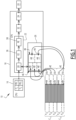
- an avionics system intended to be carried on board an aircraft, not shown, comprises an avionics platform 12.
- the avionics platform 12 comprises a central processor 16, also called CPU ( Central Processing Unit ), and a graphics processor 18, also called GPU ( Graphics Processing Unit ), the graphics processor 18 being connected to the central processor 16.
- the central processor 16 is a multi-core central processor having N distinct cores C 1 , ... C N , N being an integer greater than or equal to 2.
- the platform 12 comprises a display screen 20, connected for example to the graphics processor 18.
- the architecture of the platform 12 is a so-called asymmetric multiprocessing architecture, also called AMP architecture (from the English Asymmetrical Multi-Processing ) .
- the platform 12 is further capable of hosting N distinct operating systems OS 1 , ... OS N , each operating system OS 1 , ... OS N being associated with a respective core C 1 , ... C N .
- the central processor 16 is known per se. In the example of the figure 1 , the central processor 16 shown is, for the sake of simplification of the drawing, a processor with 2 cores C 1 , C 2 . Alternatively, not shown, the number N of distinct cores C 1 , ... C N is equal to 2 x P, where P is an integer multiple greater than or equal to 2.
- the graphics processor 18 comprises a module 22 for generating at least one set of pixels to be displayed and a module 24 for displaying each set of pixels on the display screen 20, the display module 24 being connected to the generation module 22.
- the graphics processor 18 further comprises a data storage memory 26 and a sequencer 28.
- the sequencer 28 is for example integrated into the generation module 22. Alternatively, the sequencer 28 is connected to the input of the generation module 22.
- the generation module 22 is configured to generate at least one set of pixel(s) to be displayed.
- the graphics processor 18 further comprises a module 32 for composing an image from the intermediate layer(s) generated by the generation module 22, the display module 24 then being able to display the image composed by the composition module 32.
- the generation module 22 comprises, for example, a geometric engine 36 capable of generating at least one group of geometric primitive(s) and a rendering engine 38 capable of converting each group of geometric primitive(s) into a respective set of pixel(s).
- the geometric engine 36 is also called GE (from the English Geometry Engine )
- the rendering engine 38 is also called RE (from the English Raster Engine, or even Rendering Engine ) .
- the generation module 22, and optionally the composition module 32 form a graphic creation chain for a respective image, capable of being displayed on the screen 20 by the display module 24.
- the graphic creation chain is also called a graphics pipeline.
- the composition module 32 is configured to compose each image from the corresponding intermediate layer(s), in particular by positioning said intermediate layer(s), for example relative to each other, and by superimposing them where appropriate.
- the rendering engine 38 is then configured to convert each group of geometric primitive(s) into a respective set of pixel(s), i.e. to convert the portion of vector image corresponding to the group of geometric primitive(s) into a portion of matrix image corresponding to said set of pixel(s). This conversion performed by the rendering engine 38 is also called rasterization, or matrixization.
- the reserved storage space 40 comprises N distinct storage zones 46, each zone 46 being capable of storing a respective set 42 of descriptor(s) 44, the N storage zones 46 being separate from each other.
- the sequencer 28 is further configured to process, zone 46 by zone 46, the descriptors 44 stored in the reserved storage space 40.
- Each descriptor 44 comprises one or more pieces of information chosen from the group consisting of: an identifier of a graphics context; an identifier of a graphics surface; a maximum execution time; and an identifier of a command and execution stack.
- graphical context also called graphical execution context
- graphical execution context is meant a collection of states configuring the operation of the graphical creation chain, such as for example definitions of geometric transformation laws, values of drawing colors, or erasure values, or even identifications of textures to be applied.
- the graphical execution context corresponds, for example, to the "Rendering Context", defined in the EGL standard, in particular in the document entitled “ OpenGL ® ES Native Platform Graphics Interface ", version 1.1.02 of November 2004 and following, .
- a graphics surface is a storage space for pixels, whether or not intended for display, in which the graphics creation chain performs a drawing operation.
- the person skilled in the art will then understand that the graphic surface corresponds, for example, to the “ Drawing Surface ”, also defined in the aforementioned EGL standard.
- Each storage area 46 comprises one or more distinct storage sectors 48, each sector 48 being capable of storing a respective subset 50 of descriptor(s) 44 for a respective software application capable of being executed by the core C 1 , ..., C N associated with said storage area 46, the storage sector(s) 48 being disjoint from each other.
- the sequencer 28 is further configured to process, sector 48 by sector 48, the descriptors 44 stored in a respective storage area 46.
- the reserved storage space 40 comprises two separate storage areas 46, namely a respective storage area 46 for each of the two cores C 1 , C 2 .
- the storage area 46 associated with the first core C 1 comprises three storage sectors 48, each being for example associated with a respective partition P 1 , P 3 , P 4 capable of being executed by said first core C 1 ; and the storage area 46 associated with the second core C 2 comprises two storage sectors 48, each being associated with a respective partition P 2 , P 5 capable of being executed by said second core C 2 .
- descriptors 44 are preferably distributed first by core C 1 , ..., C N , then by partition P 1 , ..., P N each executing respectively on a corresponding core C 1 , ..., C N .
- a maximum timeout is associated with each storage sector 48.
- the sequencer 28 is further configured to, when the maximum timeout is reached, interrupt the processing of the or descriptors 44 for a current sector 48 and to move on to processing the descriptor(s) 44 for a next sector 48.
- the sequencer 28 is, preferably and in the event of interruption of a respective processing of descriptor(s) 44, configured to save, in a storage location (not shown), an execution state of each descriptor 44 whose processing is interrupted, with a view to a later resumption of the interrupted processing.
- Each storage location is typically included in the memory 26, while corresponding to a memory space distinct from the reserved storage space 40.
- Each maximum delay is for example between 1 ms and 20 ms, more preferably between 2 ms and 10 ms.
- a priority level is associated with each storage sector 48.
- the sequencer 28 is further configured to process said storage sectors 48 according to a monotonic order of their priority level. For example, if the highest priority level is a level 1, and lower priority levels are levels 2 and following, the sequencer 28 is then configured to process said storage sectors 48 according to an increasing order of priority levels.
- the partitions P 1 for the first core C 1 and respectively P 2 for the second core C 2 have the highest priority level, for example level 1, and the storage sectors 48 associated with these partitions P 1 , P 2 will then be processed as a priority by the sequencer 28.
- the partitions P 3 , P 4 associated with the first core C 1 , and respectively P 5 associated with the second core C 2 have a lower priority level, for example level 2, and the storage sectors 48 associated with said partitions P 3 , P 4 and P 5 will then be processed as a lower priority by the sequencer 28, i.e. after the processing of the storage sectors 48 associated with the partitions P 1 and P 2 .
- FIG. 2 representing a flowchart of a method for displaying pixels on the screen 20, and in particular of a method for managing resources of the graphics processor 18, implemented by the graphics processor 18.
- the graphics processor 18 allocates in its memory 26 the reserved storage space 40 for the N sets 42 of descriptor(s) 44.
- each set 42 of descriptor(s) 44 is associated with a respective core C 1 , ..., C N of the multi-core central processor 16, and each descriptor 44 identifies a batch of resource(s) of the graphics processor 18 for the display of data by a software application intended to be executed via said respective core C 1 , ..., C N.
- the reserved storage space 40 comprises N distinct storage areas 46, each area 46 being capable of storing a respective set 42 of descriptor(s) 44, the allocation of each respective storage area 46 is also carried out during this initial allocation step 100. During this allocation of this storage area 46, the N storage areas 46 are distributed within the reserved storage space 40 so as to be disjoint from one another. In other words, there is no overlap between two storage areas 46.
- each respective storage area 46 comprises several distinct storage sectors 48, each sector 48 being able to store a respective subset 50 of descriptor(s) 44 for a respective software application
- the allocation of said storage sectors 48 is also carried out during this allocation step 100.
- each sector 48 is allocated within the storage area 46 corresponding to the core C 1 , ..., C N which is able to execute the software application associated with said sector 48.
- the graphics processor 18 regularly performs a step 110 of processing descriptors 44, followed by a step 120 of image composition, followed by an optional step 130 of mixing with a video, followed finally by a step 140 of displaying on the screen 20 the image, possibly with the video, generated during the preceding steps 110 to 130.
- the graphics processor 18, and in particular its sequencer 28 successively processes the descriptors 44 stored in the reserved storage space 40.
- the sequencer 28 is configured to process, zone 46 by zone 46, the descriptors 44 stored in the reserved storage space 40.
- sequencer 28 is configured to process, sector 48 by sector 48, the descriptors 44 stored in a respective storage area 46.
- the sequencer 28 interrupts, when a respective maximum timeout is reached, the processing of the descriptor(s) 44 for a current sector 48, and then moves on to the processing of the descriptor(s) 44 for the following sector 48.
- the sequencer 28 preferably saves a respective execution state of each descriptor 44 whose processing is interrupted, this in the storage location and with a view to a later resumption of said interrupted processing.
- the sequencer 28 When optionally a respective priority level is still respected at each sector 48, the sequencer 28 preferably processes said storage sectors 48 according to a monotonic order of their respective priority levels.
- this processing step 110 makes it possible, via the processing of said descriptors 44, to execute the rendering of graphic commands, previously produced by the central processor 16.
- This execution of the rendering of the graphic commands comprises, for example, a generation of geometric primitive(s) carried out by the geometric engine 36, also denoted GE, followed by a conversion of the geometric primitive(s) generated into one or more respective sets of pixel(s), this conversion being carried out by the rendering engine 38, also denoted RE.
- the graphics processor 18 performs, via its composition module 32 and during the following step 130, the image composition.
- This image composition typically consists of composing each image from intermediate layers received from the generation module 22, and consists more particularly of a positioning of the intermediate layers relative to each other, as well as superimposing certain layers on each other.
- composition step 130 is optionally followed by a mixing step 140 during which the graphics processor 18 mixes, via its display module 24, also playing the role of mixing module, an image composed by the composition module 32 with a video or a video stream, stored in the storage memory 26, in order to display during the following step 150, the mixture of an image and a video.
- a mixing step 140 during which the graphics processor 18 mixes, via its display module 24, also playing the role of mixing module, an image composed by the composition module 32 with a video or a video stream, stored in the storage memory 26, in order to display during the following step 150, the mixture of an image and a video.
- the display module 24 then displays, during the display step 150, the composite image(s) on the screen 20.
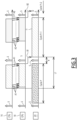
- the first operating mode corresponds to an execution, by the graphics processor 18, of the rendering of the graphics commands produced by the central processor 16, this as and when they are produced by the central processor 16.
- the graphics commands produced by the central processor 16 are directly transmitted to the graphics processor 18, during the same cycle, as represented by the arrows A1 for the cycle P, or by the arrows A2 for the cycle P+1, so that the rendering of these graphics commands is executed by the graphics processor 18 during this same cycle.
- each arrow A1, A2 on the figure 3 represents the transmission of both graphics command(s) and associated descriptor(s) 44, this from the central processor 16 to the graphics processor 18.
- the graphics commands produced by the central processor 16 during the cycle P, and whose rendering was executed by the graphics processor 18 during the same cycle P then result in the display of an image during the following cycle P+1, as illustrated with the display of the image I1 on the figure 3 .
- P+1 a switching is necessary in order to move from the display of one image to the display of the following image, each switching being represented by a vertical arrow S in a thick line, and resulting in a period of white B on the display screen 20.
- FIG 4 illustrates the second mode of operation, called timed, in which the graphic commands produced during cycle P by the central processor 16 are only processed by the graphic processor 18 during the following cycle P+1, which then results in the display of the image during the still following cycle P+2 on the display screen 20.
- the image I3 displayed during the cycle P+2 thus results from graphic commands produced by the central processor 16 during the cycle P, then transmitted, with the associated descriptors 44, to the graphics processor 18 during the switching S between the cycle P and the cycle P+1, as represented by the arrow A3.
- the execution of the graphic rendering of the commands produced during the cycle P is then carried out by the graphics processor 18 during the following cycle P+1 and the image I3 is then displayed during the still following cycle P+2, the data relating to the relative image I3 being transmitted between the graphics processor 18 and the display screen 20 during the switching S between the cycle P+1 and the cycle P+2, as represented by the arrow B3.
- the graphics commands produced by the central processor 16 during the cycle P+1 are transmitted, with the associated descriptors 44, during the switching S between the cycle P+1 and the cycle P+2, as represented by the arrow A4, so that the rendering of these graphics commands is executed during the following cycle P+2 by the graphics processor 18, to finally result in the display of the image I4 during the still following cycle P+3, the information to be displayed for the image I4 being transmitted between the graphics processor 18 and the display screen 20 during the switching S between the cycle P+2 and the cycle P+3, as represented by the arrow B4.
- the person skilled in the art will then observe that according to the first mode of operation, said to be immediate and visible to the figure 3 , the latency between a time instant of production of the graphic command and the resulting display on the display screen 20 is reduced, and is in particular lower than according to the second operating mode, called timed.
- the latency according to the first operating mode and the latency according to the second operating mode
- the person skilled in the art will observe that the latency, represented by the arrow L1 visible at figure 3 , for displaying image I1 according to the first operating mode is much lower than the latency, represented by the arrow L3 visible in the figure 4 , for displaying the I3 image according to the second operating mode.
- the first operating mode requires having a central processor 16 that is synchronous with the graphics processor 18, and the execution times of the central processor 16 then depend on the corresponding execution times of the graphics processor 18, which may prove to be penalizing in terms of performance.
- the central processor 16 operates asynchronously with respect to the graphics processor 18, and the processing times are then decoupled between the central processor 16 and the graphics processor 18.
- the third operating mode is a mixture of the first and second operating modes described above. More precisely, during each cycle P, P+1, P+2, the avionics system 10 operates partially in timed mode, corresponding to the second operating mode described above with regard to the figure 4 , and partially in immediate mode, corresponding to the first operating mode described with regard to the figure 3 .
- the central processor 16 being a multi-core processor, this distribution of operating modes is for example carried out core by core, with one or more cores operating in immediate mode and one or more cores operating in timed mode.
- certain graphic commands produced by the central processor 16 are transmitted with the corresponding descriptors 44 during the same respective cycle, to the graphics processor 18 so that their rendering is executed during this same cycle, this immediate transmission being illustrated by the arrows A7 for the cycle P, A9 for the cycle P+1 and A11 for the cycle P+2.
- the portions I6 and I9 of images displayed during the cycle P+2 on the display screen 20 result, on the one hand, from the graphics commands produced, for example by the first core C1 during the cycle P, transmitted according to the arrow A6 during the switching S between the cycle P and the cycle P+1 to the graphics processor 18, the rendering of which is then executed during the cycle P+1 by the graphics processor 18, said rendering then finally being transmitted, according to the arrow B6, during the switching S between the cycle P+1 and the cycle P+2, with a view to displaying the image portion I6 during the cycle P+2; and on the other hand, from graphics commands produced during the cycle P+1, for example by the second core C2 , said commands being transmitted according to the arrows A9 during this same cycle P+1 to the graphics processor 18 so that their rendering is executed during this same cycle P+1, and the rendering then being transmitted during the switching S between the cycle P+1 and the cycle P+2 according to the arrow B9, with a view to displaying the image portion I9 during the cycle P+2.
- the latency, represented by the arrow L9 for the image portion I9 is much lower than the latency, represented by the arrow L6 for the image portion I6, which in other words makes it possible to have differentiated latencies for image portions I6, I9 displayed during the same cycle, such as cycle P+2 in this example of the figure 5 .
- this third mode of operation illustrated in the figure 5 allows data that is important to the avionics system 10 to be displayed more quickly, while also allowing less important data, such as background data, to be displayed more slowly.
- Mixed mode then typically allows important data to be displayed in immediate mode, i.e. more quickly, such as position, attitude, roll, altitude, i.e. minimum aircraft piloting parameters, in order to prioritize flight safety, with less display latency for this crucial data.
- the reserved storage space 40 and the successive processing of the descriptors 44 by the sequencer 28 allows the graphics processor 18 to manage accesses to its resources emanating from several cores C 1 , ..., C N of the central processor 16, which then allows resource sharing to be carried out directly at the level of the graphics processor 18, rather than at the level of an operating system which would be common to the plurality of cores within the central processor 16.
- the reserved storage space 40 for the descriptors 44 and the processing of said descriptors 44 by the sequencer 28 then makes it possible to have an operation of the avionics platform 12 according to the asymmetric multiprocessing architecture, called AMP architecture.
Landscapes
- Engineering & Computer Science (AREA)
- Theoretical Computer Science (AREA)
- Computer Hardware Design (AREA)
- Physics & Mathematics (AREA)
- General Physics & Mathematics (AREA)
- General Engineering & Computer Science (AREA)
- Software Systems (AREA)
- Computing Systems (AREA)
- Image Generation (AREA)
- Controls And Circuits For Display Device (AREA)
- Digital Computer Display Output (AREA)
Claims (6)
- Grafikprozessor (18), der dazu bestimmt ist, mit einem Mehrkern-Zentralprozessor (16) verbunden zu sein, der N verschiedene Kerne (C1, ..., CN) aufweist, wobei N eine ganze Zahl größer als oder gleich wie 2 ist, der Grafikprozessor (18) umfassend einen Speicher (26),dadurch gekennzeichnet, dass der Speicher (26) einen reservierten Raum (40) zum Speichern von N Einheiten (42) von Deskriptor(en) (44) umfasst, wobei jede Einheit (42) von Deskriptor(en) (44) mit einem jeweiligen Kern (C1, ..., CN) des Mehrkern-Zentralprozessors (16) assoziiert ist, wobei jeder Deskriptor (44) einen Satz von Ressource(n) des Grafikprozessors (18) zur Anzeige von Daten durch eine Softwareanwendung identifiziert, die dazu bestimmt ist, über den jeweiligen Kern (C1, ..., CN) ausgeführt zu werden,der reservierte Speicherraum (40) umfassend N verschiedene Speicherbereiche (46), wobei jeder Bereich (46) geeignet ist, um eine jeweilige Einheit (42) von Deskriptoren) (44) zu speichern, wobei die N Speicherbereiche (46) voneinander getrennt sind,jeder Speicherbereich (46) umfassend einen oder mehrere verschiedene Speichersektoren (48), wobei jeder Sektor (48) geeignet ist, um eine jeweilige Teileinheit (50) von Deskriptor(en) (44) für eine jeweilige Softwareanwendung zu speichern, die geeignet ist, um von dem Kern (C1, ..., CN) ausgeführt zu werden, der mit dem Speicherbereich (46) assoziiert ist, wobei der oder die Speichersektoren (48) voneinander getrennt sind, wobei jeder Speichersektor (48) mit einer jeweiligen Partition (P1, ..., P5) assoziiert ist, die geeignet ist, um von einem entsprechenden Kern (C1, ..., CN) ausgeführt zu werden, unddass der Grafikprozessor (18) ferner einen Sequenzer (28) umfasst, der konfiguriert ist, um die in dem reservierten Speicherraum (40) gespeicherten Deskriptoren (44) nacheinander zu verarbeiten, wobei der Sequenzer (28) konfiguriert ist, um die in einem jeweiligen Speicherbereich (46) gespeicherten Deskriptoren (44) Sektor (48) für Sektor (48) zu verarbeiten.
- Grafikprozessor (18) nach Anspruch 1, wobei mit jedem Speichersektor (48) eine maximale Zeitverzögerung assoziiert ist und der Sequenzer (28) konfiguriert ist, um, wenn die maximale Zeitverzögerung erreicht ist, die Verarbeitung des oder der Deskriptoren (44) für einen aktuellen Sektor (48) zu unterbrechen und zu der Verarbeitung des oder der Deskriptoren (44) für einen nächsten Sektor (48) überzugehen;
wobei der Sequenzer (28) vorzugsweise und im Falle einer Unterbrechung einer jeweiligen Verarbeitung von Deskriptor(en) (44) konfiguriert ist, um an einem Speicherort einen Ausführungszustand von jedem Deskriptor (44), dessen Verarbeitung unterbrochen ist, für eine nachfolgende Wiederaufnahme der unterbrochenen Verarbeitung zu speichern. - Grafikprozessor (18) nach Anspruch 1 oder 2, wobei mit jedem Sektor (48) eine Prioritätsstufe assoziiert ist, und wenn ein jeweiliger Speicherbereich mehrere verschiedene Speichersektoren (48) umfasst, der Sequenzer (28) ferner konfiguriert ist, um die Speichersektoren (48) in einer monotonen Reihenfolge ihrer Prioritätsstufen zu verarbeiten.
- Grafikprozessor (18) nach einem der vorherigen Ansprüche, wobei jeder Deskriptor (44) eine oder mehrere Informationen enthält, die ausgewählt sind aus der Gruppe, bestehend aus: einem Identifikator eines Grafikkontexts; einem Identifikator einer Grafikoberfläche; einer maximalen Ausführungszeit; und einem Identifikator eines Befehls- und Ausführungsstapels.
- Plattform (12), umfassend einen Grafikprozessor (18) und einen Mehrkern-Zentralprozessor (16), der N verschiedene Kerne (C1, ..., CN) aufweist, wobei N eine ganze Zahl größer als oder gleich wie 2 ist, wobei der Grafikprozessor (18) mit dem Zentralprozessor (16) verbunden ist,
dadurch gekennzeichnet, dass der Grafikprozessor (18) nach einem der vorherigen Ansprüche ist. - Verfahren zur Verwaltung von Ressource(n) eines Grafikprozessors (18), wobei das Verfahren durch den Grafikprozessor (18) implementiert wird, der Grafikprozessor (18) umfassend einen Speicher (26) und ist mit einem Mehrkern-Zentralprozessor (16) verbunden, der N verschiedene Kerne (C1, ..., CN) aufweist, wobei N eine ganze Zahl größer als oder gleich wie 2 ist,das Verfahren umfassend die Schritte, die aus Folgendem bestehen:- Zuweisen (100), in dem Speicher (26), eines reservierten Raums (40) zur Speicherung von N Einheiten (42) von Deskriptor(en) (44), wobei jede Einheit (42) von Deskriptor(en) (44) mit einem jeweiligen Kern (C1, ..., CN) des Mehrkern-Zentralprozessors (16) assoziiert ist, wobei jeder Deskriptor (44) einen Satz von Ressource(n) des Grafikprozessors (18) zur Anzeige von Daten durch eine Softwareanwendung identifiziert, die dazu bestimmt ist, über den jeweiligen Kern (C1, ..., CN) ausgeführt zu werden,der reservierte Speicherraum (40) umfassend N verschiedene Speicherbereiche (46), wobei jeder Bereich (46) geeignet ist, um eine jeweilige Einheit (42) von Deskriptor(en) (44) zu speichern, wobei die N Speicherbereiche (46) voneinander getrennt sind,jeder Speicherbereich (46) umfassend einen oder mehrere verschiedene Speichersektoren (48), wobei jeder Sektor (48) geeignet ist, um eine jeweilige Teileinheit (50) von Deskriptor(en) (44) für eine jeweilige Softwareanwendung zu speichern, die geeignet ist, um von dem Kern (C1, ..., CN) ausgeführt zu werden, der mit dem Speicherbereich (46) assoziiert ist, wobei der oder die Speichersektoren (48) voneinander getrennt sind, wobei jeder Speichersektor (48) mit einer jeweiligen Partition (P1, ..., P5) assoziiert ist, die geeignet ist, um von einem entsprechenden Kern (C1, ..., CN) ausgeführt zu werden, und- nacheinander Verarbeiten (110) der in dem reservierten Speicherraum (40) gespeicherten Deskriptoren (44), und Sektor (48) für Sektor (48) der Deskriptoren (44), die in einem jeweiligen Speicherbereich (46) gespeichert sind.
Applications Claiming Priority (1)
| Application Number | Priority Date | Filing Date | Title |
|---|---|---|---|
| FR1914873A FR3105469B1 (fr) | 2019-12-19 | 2019-12-19 | Processeur graphique, plateforme comprenant un tel processeur graphique et un processeur central multicoeurs, et procede de gestion de ressource (s) d'un tel processeur graphique |
Publications (2)
| Publication Number | Publication Date |
|---|---|
| EP3839733A1 EP3839733A1 (de) | 2021-06-23 |
| EP3839733B1 true EP3839733B1 (de) | 2025-01-01 |
Family
ID=71094415
Family Applications (1)
| Application Number | Title | Priority Date | Filing Date |
|---|---|---|---|
| EP20215327.6A Active EP3839733B1 (de) | 2019-12-19 | 2020-12-18 | Grafikprozessor, plattform mit einem solchen grafikprozessor und einem mehrkernigen zentralprozessor, und verfahren zur verwaltung der ressource(n) eines solchen grafikprozessors |
Country Status (4)
| Country | Link |
|---|---|
| US (1) | US20210192675A1 (de) |
| EP (1) | EP3839733B1 (de) |
| CN (1) | CN113010467A (de) |
| FR (1) | FR3105469B1 (de) |
Families Citing this family (1)
| Publication number | Priority date | Publication date | Assignee | Title |
|---|---|---|---|---|
| CN113645412B (zh) * | 2021-10-15 | 2021-12-24 | 北京创米智汇物联科技有限公司 | 启动方法、装置、摄像机及计算机可读存储介质 |
Family Cites Families (6)
| Publication number | Priority date | Publication date | Assignee | Title |
|---|---|---|---|---|
| US9092267B2 (en) * | 2011-06-20 | 2015-07-28 | Qualcomm Incorporated | Memory sharing in graphics processing unit |
| US20150091912A1 (en) * | 2013-09-27 | 2015-04-02 | Nvidia Corporation | Independent memory heaps for scalable link interface technology |
| FR3025628B1 (fr) * | 2014-09-04 | 2017-12-22 | Centre Nat D'etudes Spatiales (Cnes) | Systeme embarque mettant en oeuvre des fonctions avioniques critiques |
| US10162405B2 (en) * | 2015-06-04 | 2018-12-25 | Intel Corporation | Graphics processor power management contexts and sequential control loops |
| FR3045866B1 (fr) * | 2015-12-16 | 2018-02-02 | Thales | Calculateur comprenant un processeur multi-coeurs et un procede de controle |
| US20200027189A1 (en) * | 2018-07-23 | 2020-01-23 | Qualcomm Incorporated | Efficient dependency detection for concurrent binning gpu workloads |
-
2019
- 2019-12-19 FR FR1914873A patent/FR3105469B1/fr active Active
-
2020
- 2020-12-14 US US17/120,911 patent/US20210192675A1/en not_active Abandoned
- 2020-12-15 CN CN202011481202.4A patent/CN113010467A/zh active Pending
- 2020-12-18 EP EP20215327.6A patent/EP3839733B1/de active Active
Also Published As
| Publication number | Publication date |
|---|---|
| US20210192675A1 (en) | 2021-06-24 |
| CN113010467A (zh) | 2021-06-22 |
| FR3105469A1 (fr) | 2021-06-25 |
| EP3839733A1 (de) | 2021-06-23 |
| FR3105469B1 (fr) | 2021-12-31 |
Similar Documents
| Publication | Publication Date | Title |
|---|---|---|
| GB2559042B (en) | Allocation of tiles to processing engines in a graphics processing system | |
| US7671862B1 (en) | Systems and methods for providing an enhanced graphics pipeline | |
| JP4583720B2 (ja) | グラフィックス・システム内で中間ターゲットを提供するためのシステムおよび方法 | |
| WO2021236668A1 (en) | Neural super-sampling for real-time rendering | |
| EP1527599B1 (de) | Verfahren und system zur echt-zeit mischung von synthesebildern und videobildern | |
| EP1594091A2 (de) | System und verfahren zum Bereitstellen von verbesserter Grafikdatenpipeline | |
| US11900500B2 (en) | System and method for efficient multi-GPU rendering of geometry by subdividing geometry | |
| NO326851B1 (no) | Systemer og fremgangsmater for tilveiebringelse av styrbar tekstursampling | |
| FR2964236A1 (fr) | Dispositif et procede de generation d'images multifenetres a priorite variable | |
| CN115335866A (zh) | 在渲染时通过几何图形分析进行几何图形的高效多gpu渲染的系统和方法 | |
| EP3839733B1 (de) | Grafikprozessor, plattform mit einem solchen grafikprozessor und einem mehrkernigen zentralprozessor, und verfahren zur verwaltung der ressource(n) eines solchen grafikprozessors | |
| US12118641B2 (en) | System and method for efficient multi-GPU rendering of geometry by performing geometry analysis while rendering | |
| CN117618883B (zh) | 用于图形处理的方法、计算机可读介质及计算机系统 | |
| US20250124644A1 (en) | Performing geometry analysis before multi-gpu rendering of geometry | |
| FR2964775A1 (fr) | Procede d'estimation de l'occultation dans un environnement virtuel | |
| US20210241411A1 (en) | System and method for efficient multi-gpu rendering of geometry by generating information in one rendering phase for use in another rendering phase | |
| US9818174B2 (en) | Streamlined handling of monitor topology changes | |
| EP3792866B1 (de) | Grafischer prozessor und entsprechendes anzeigeverfahren einer gesamtheit von pixeln, entsprechende plattform und entsprechendes flugzeugelektroniksystem | |
| CN116188241B (zh) | 图形处理器、操作方法和机器可读存储介质 | |
| FR2948800A1 (fr) | Procede d'estimation de diffusion de la lumiere | |
| FR2994500A1 (fr) | Procede d'optimisation de l'execution d'un pipeline graphique | |
| FR2917199A1 (fr) | Generateur de code source pour une carte graphique | |
| US20250322594A1 (en) | Optimized virtual reality system | |
| CA2535573A1 (fr) | Procede et dispositif de generation d'elements specifiques, d'une image et procede et dispositif de generation d'images de synthese comportant de tels elements specifiques | |
| Takayama et al. | Implementation of Cell-Projection Parallel Volume Rendering with Dynamic Load Balancing. |
Legal Events
| Date | Code | Title | Description |
|---|---|---|---|
| PUAI | Public reference made under article 153(3) epc to a published international application that has entered the european phase |
Free format text: ORIGINAL CODE: 0009012 |
|
| STAA | Information on the status of an ep patent application or granted ep patent |
Free format text: STATUS: THE APPLICATION HAS BEEN PUBLISHED |
|
| AK | Designated contracting states |
Kind code of ref document: A1 Designated state(s): AL AT BE BG CH CY CZ DE DK EE ES FI FR GB GR HR HU IE IS IT LI LT LU LV MC MK MT NL NO PL PT RO RS SE SI SK SM TR |
|
| STAA | Information on the status of an ep patent application or granted ep patent |
Free format text: STATUS: REQUEST FOR EXAMINATION WAS MADE |
|
| 17P | Request for examination filed |
Effective date: 20211124 |
|
| RBV | Designated contracting states (corrected) |
Designated state(s): AL AT BE BG CH CY CZ DE DK EE ES FI FR GB GR HR HU IE IS IT LI LT LU LV MC MK MT NL NO PL PT RO RS SE SI SK SM TR |
|
| P01 | Opt-out of the competence of the unified patent court (upc) registered |
Effective date: 20230425 |
|
| GRAP | Despatch of communication of intention to grant a patent |
Free format text: ORIGINAL CODE: EPIDOSNIGR1 |
|
| STAA | Information on the status of an ep patent application or granted ep patent |
Free format text: STATUS: GRANT OF PATENT IS INTENDED |
|
| INTG | Intention to grant announced |
Effective date: 20240821 |
|
| GRAS | Grant fee paid |
Free format text: ORIGINAL CODE: EPIDOSNIGR3 |
|
| GRAA | (expected) grant |
Free format text: ORIGINAL CODE: 0009210 |
|
| STAA | Information on the status of an ep patent application or granted ep patent |
Free format text: STATUS: THE PATENT HAS BEEN GRANTED |
|
| AK | Designated contracting states |
Kind code of ref document: B1 Designated state(s): AL AT BE BG CH CY CZ DE DK EE ES FI FR GB GR HR HU IE IS IT LI LT LU LV MC MK MT NL NO PL PT RO RS SE SI SK SM TR |
|
| REG | Reference to a national code |
Ref country code: GB Ref legal event code: FG4D Free format text: NOT ENGLISH |
|
| REG | Reference to a national code |
Ref country code: CH Ref legal event code: EP |
|
| REG | Reference to a national code |
Ref country code: DE Ref legal event code: R096 Ref document number: 602020043991 Country of ref document: DE |
|
| REG | Reference to a national code |
Ref country code: IE Ref legal event code: FG4D Free format text: LANGUAGE OF EP DOCUMENT: FRENCH |
|
| REG | Reference to a national code |
Ref country code: LT Ref legal event code: MG9D |
|
| REG | Reference to a national code |
Ref country code: NL Ref legal event code: MP Effective date: 20250101 |
|
| REG | Reference to a national code |
Ref country code: AT Ref legal event code: MK05 Ref document number: 1756971 Country of ref document: AT Kind code of ref document: T Effective date: 20250101 |
|
| PG25 | Lapsed in a contracting state [announced via postgrant information from national office to epo] |
Ref country code: NL Free format text: LAPSE BECAUSE OF FAILURE TO SUBMIT A TRANSLATION OF THE DESCRIPTION OR TO PAY THE FEE WITHIN THE PRESCRIBED TIME-LIMIT Effective date: 20250101 |
|
| PG25 | Lapsed in a contracting state [announced via postgrant information from national office to epo] |
Ref country code: FI Free format text: LAPSE BECAUSE OF FAILURE TO SUBMIT A TRANSLATION OF THE DESCRIPTION OR TO PAY THE FEE WITHIN THE PRESCRIBED TIME-LIMIT Effective date: 20250101 |
|
| PG25 | Lapsed in a contracting state [announced via postgrant information from national office to epo] |
Ref country code: PL Free format text: LAPSE BECAUSE OF FAILURE TO SUBMIT A TRANSLATION OF THE DESCRIPTION OR TO PAY THE FEE WITHIN THE PRESCRIBED TIME-LIMIT Effective date: 20250101 |
|
| PG25 | Lapsed in a contracting state [announced via postgrant information from national office to epo] |
Ref country code: ES Free format text: LAPSE BECAUSE OF FAILURE TO SUBMIT A TRANSLATION OF THE DESCRIPTION OR TO PAY THE FEE WITHIN THE PRESCRIBED TIME-LIMIT Effective date: 20250101 |
|
| PG25 | Lapsed in a contracting state [announced via postgrant information from national office to epo] |
Ref country code: NO Free format text: LAPSE BECAUSE OF FAILURE TO SUBMIT A TRANSLATION OF THE DESCRIPTION OR TO PAY THE FEE WITHIN THE PRESCRIBED TIME-LIMIT Effective date: 20250401 Ref country code: IS Free format text: LAPSE BECAUSE OF FAILURE TO SUBMIT A TRANSLATION OF THE DESCRIPTION OR TO PAY THE FEE WITHIN THE PRESCRIBED TIME-LIMIT Effective date: 20250501 |
|
| PG25 | Lapsed in a contracting state [announced via postgrant information from national office to epo] |
Ref country code: HR Free format text: LAPSE BECAUSE OF FAILURE TO SUBMIT A TRANSLATION OF THE DESCRIPTION OR TO PAY THE FEE WITHIN THE PRESCRIBED TIME-LIMIT Effective date: 20250101 |
|
| PG25 | Lapsed in a contracting state [announced via postgrant information from national office to epo] |
Ref country code: LV Free format text: LAPSE BECAUSE OF FAILURE TO SUBMIT A TRANSLATION OF THE DESCRIPTION OR TO PAY THE FEE WITHIN THE PRESCRIBED TIME-LIMIT Effective date: 20250101 Ref country code: PT Free format text: LAPSE BECAUSE OF FAILURE TO SUBMIT A TRANSLATION OF THE DESCRIPTION OR TO PAY THE FEE WITHIN THE PRESCRIBED TIME-LIMIT Effective date: 20250502 |
|
| PG25 | Lapsed in a contracting state [announced via postgrant information from national office to epo] |
Ref country code: GR Free format text: LAPSE BECAUSE OF FAILURE TO SUBMIT A TRANSLATION OF THE DESCRIPTION OR TO PAY THE FEE WITHIN THE PRESCRIBED TIME-LIMIT Effective date: 20250402 Ref country code: BG Free format text: LAPSE BECAUSE OF FAILURE TO SUBMIT A TRANSLATION OF THE DESCRIPTION OR TO PAY THE FEE WITHIN THE PRESCRIBED TIME-LIMIT Effective date: 20250101 |
|
| PG25 | Lapsed in a contracting state [announced via postgrant information from national office to epo] |
Ref country code: AT Free format text: LAPSE BECAUSE OF FAILURE TO SUBMIT A TRANSLATION OF THE DESCRIPTION OR TO PAY THE FEE WITHIN THE PRESCRIBED TIME-LIMIT Effective date: 20250101 |
|
| PG25 | Lapsed in a contracting state [announced via postgrant information from national office to epo] |
Ref country code: CZ Free format text: LAPSE BECAUSE OF FAILURE TO SUBMIT A TRANSLATION OF THE DESCRIPTION OR TO PAY THE FEE WITHIN THE PRESCRIBED TIME-LIMIT Effective date: 20250101 |
|
| PG25 | Lapsed in a contracting state [announced via postgrant information from national office to epo] |
Ref country code: SE Free format text: LAPSE BECAUSE OF FAILURE TO SUBMIT A TRANSLATION OF THE DESCRIPTION OR TO PAY THE FEE WITHIN THE PRESCRIBED TIME-LIMIT Effective date: 20250101 |
|
| REG | Reference to a national code |
Ref country code: DE Ref legal event code: R097 Ref document number: 602020043991 Country of ref document: DE |
|
| PG25 | Lapsed in a contracting state [announced via postgrant information from national office to epo] |
Ref country code: SM Free format text: LAPSE BECAUSE OF FAILURE TO SUBMIT A TRANSLATION OF THE DESCRIPTION OR TO PAY THE FEE WITHIN THE PRESCRIBED TIME-LIMIT Effective date: 20250101 |
|
| PG25 | Lapsed in a contracting state [announced via postgrant information from national office to epo] |
Ref country code: DK Free format text: LAPSE BECAUSE OF FAILURE TO SUBMIT A TRANSLATION OF THE DESCRIPTION OR TO PAY THE FEE WITHIN THE PRESCRIBED TIME-LIMIT Effective date: 20250101 |
|
| PG25 | Lapsed in a contracting state [announced via postgrant information from national office to epo] |
Ref country code: IT Free format text: LAPSE BECAUSE OF FAILURE TO SUBMIT A TRANSLATION OF THE DESCRIPTION OR TO PAY THE FEE WITHIN THE PRESCRIBED TIME-LIMIT Effective date: 20250101 |
|
| PG25 | Lapsed in a contracting state [announced via postgrant information from national office to epo] |
Ref country code: EE Free format text: LAPSE BECAUSE OF FAILURE TO SUBMIT A TRANSLATION OF THE DESCRIPTION OR TO PAY THE FEE WITHIN THE PRESCRIBED TIME-LIMIT Effective date: 20250101 |
|
| PG25 | Lapsed in a contracting state [announced via postgrant information from national office to epo] |
Ref country code: RO Free format text: LAPSE BECAUSE OF FAILURE TO SUBMIT A TRANSLATION OF THE DESCRIPTION OR TO PAY THE FEE WITHIN THE PRESCRIBED TIME-LIMIT Effective date: 20250101 |
|
| PG25 | Lapsed in a contracting state [announced via postgrant information from national office to epo] |
Ref country code: SK Free format text: LAPSE BECAUSE OF FAILURE TO SUBMIT A TRANSLATION OF THE DESCRIPTION OR TO PAY THE FEE WITHIN THE PRESCRIBED TIME-LIMIT Effective date: 20250101 |
|
| PLBE | No opposition filed within time limit |
Free format text: ORIGINAL CODE: 0009261 |
|
| STAA | Information on the status of an ep patent application or granted ep patent |
Free format text: STATUS: NO OPPOSITION FILED WITHIN TIME LIMIT |
|
| 26N | No opposition filed |
Effective date: 20251002 |
|
| PGFP | Annual fee paid to national office [announced via postgrant information from national office to epo] |
Ref country code: GB Payment date: 20251229 Year of fee payment: 6 |
|
| PGFP | Annual fee paid to national office [announced via postgrant information from national office to epo] |
Ref country code: FR Payment date: 20251230 Year of fee payment: 6 |
|
| PGFP | Annual fee paid to national office [announced via postgrant information from national office to epo] |
Ref country code: DE Payment date: 20251231 Year of fee payment: 6 |