EP3839504A2 - Sensor - Google Patents
Sensor Download PDFInfo
- Publication number
- EP3839504A2 EP3839504A2 EP20207763.2A EP20207763A EP3839504A2 EP 3839504 A2 EP3839504 A2 EP 3839504A2 EP 20207763 A EP20207763 A EP 20207763A EP 3839504 A2 EP3839504 A2 EP 3839504A2
- Authority
- EP
- European Patent Office
- Prior art keywords
- electrode
- sensor
- electrodes
- attracting
- outer peripheral
- Prior art date
- Legal status (The legal status is an assumption and is not a legal conclusion. Google has not performed a legal analysis and makes no representation as to the accuracy of the status listed.)
- Granted
Links
Images






Classifications
-
- G—PHYSICS
- G01—MEASURING; TESTING
- G01N—INVESTIGATING OR ANALYSING MATERIALS BY DETERMINING THEIR CHEMICAL OR PHYSICAL PROPERTIES
- G01N27/00—Investigating or analysing materials by the use of electric, electrochemical, or magnetic means
- G01N27/02—Investigating or analysing materials by the use of electric, electrochemical, or magnetic means by investigating impedance
- G01N27/04—Investigating or analysing materials by the use of electric, electrochemical, or magnetic means by investigating impedance by investigating resistance
- G01N27/043—Investigating or analysing materials by the use of electric, electrochemical, or magnetic means by investigating impedance by investigating resistance of a granular material
-
- G—PHYSICS
- G01—MEASURING; TESTING
- G01N—INVESTIGATING OR ANALYSING MATERIALS BY DETERMINING THEIR CHEMICAL OR PHYSICAL PROPERTIES
- G01N27/00—Investigating or analysing materials by the use of electric, electrochemical, or magnetic means
- G01N27/02—Investigating or analysing materials by the use of electric, electrochemical, or magnetic means by investigating impedance
- G01N27/04—Investigating or analysing materials by the use of electric, electrochemical, or magnetic means by investigating impedance by investigating resistance
- G01N27/041—Investigating or analysing materials by the use of electric, electrochemical, or magnetic means by investigating impedance by investigating resistance of a solid body
-
- G—PHYSICS
- G01—MEASURING; TESTING
- G01N—INVESTIGATING OR ANALYSING MATERIALS BY DETERMINING THEIR CHEMICAL OR PHYSICAL PROPERTIES
- G01N15/00—Investigating characteristics of particles; Investigating permeability, pore-volume or surface-area of porous materials
- G01N15/06—Investigating concentration of particle suspensions
- G01N15/0606—Investigating concentration of particle suspensions by collecting particles on a support
-
- G—PHYSICS
- G01—MEASURING; TESTING
- G01N—INVESTIGATING OR ANALYSING MATERIALS BY DETERMINING THEIR CHEMICAL OR PHYSICAL PROPERTIES
- G01N15/00—Investigating characteristics of particles; Investigating permeability, pore-volume or surface-area of porous materials
- G01N15/06—Investigating concentration of particle suspensions
- G01N15/0656—Investigating concentration of particle suspensions using electric, e.g. electrostatic methods or magnetic methods
-
- G—PHYSICS
- G01—MEASURING; TESTING
- G01N—INVESTIGATING OR ANALYSING MATERIALS BY DETERMINING THEIR CHEMICAL OR PHYSICAL PROPERTIES
- G01N27/00—Investigating or analysing materials by the use of electric, electrochemical, or magnetic means
- G01N27/02—Investigating or analysing materials by the use of electric, electrochemical, or magnetic means by investigating impedance
- G01N27/04—Investigating or analysing materials by the use of electric, electrochemical, or magnetic means by investigating impedance by investigating resistance
- G01N27/06—Investigating or analysing materials by the use of electric, electrochemical, or magnetic means by investigating impedance by investigating resistance of a liquid
-
- G—PHYSICS
- G01—MEASURING; TESTING
- G01N—INVESTIGATING OR ANALYSING MATERIALS BY DETERMINING THEIR CHEMICAL OR PHYSICAL PROPERTIES
- G01N27/00—Investigating or analysing materials by the use of electric, electrochemical, or magnetic means
- G01N27/02—Investigating or analysing materials by the use of electric, electrochemical, or magnetic means by investigating impedance
- G01N27/04—Investigating or analysing materials by the use of electric, electrochemical, or magnetic means by investigating impedance by investigating resistance
- G01N27/12—Investigating or analysing materials by the use of electric, electrochemical, or magnetic means by investigating impedance by investigating resistance of a solid body in dependence upon absorption of a fluid; of a solid body in dependence upon reaction with a fluid, for detecting components in the fluid
- G01N27/122—Circuits particularly adapted therefor, e.g. linearising circuits
-
- G—PHYSICS
- G01—MEASURING; TESTING
- G01N—INVESTIGATING OR ANALYSING MATERIALS BY DETERMINING THEIR CHEMICAL OR PHYSICAL PROPERTIES
- G01N33/00—Investigating or analysing materials by specific methods not covered by groups G01N1/00 - G01N31/00
- G01N33/26—Oils; Viscous liquids; Paints; Inks
- G01N33/28—Oils, i.e. hydrocarbon liquids
- G01N33/2835—Specific substances contained in the oils or fuels
- G01N33/2858—Metal particles
-
- G—PHYSICS
- G01—MEASURING; TESTING
- G01N—INVESTIGATING OR ANALYSING MATERIALS BY DETERMINING THEIR CHEMICAL OR PHYSICAL PROPERTIES
- G01N15/00—Investigating characteristics of particles; Investigating permeability, pore-volume or surface-area of porous materials
- G01N2015/0042—Investigating dispersion of solids
- G01N2015/0053—Investigating dispersion of solids in liquids, e.g. trouble
Definitions
- the present invention relates to a sensor.
- a mechanical device such as a speed reducer is housed in a housing filled with a lubricating oil in order to prevent the mechanical parts such as gears from being damaged
- abrasion powder for example, a conductive substance such as iron powder
- the abrasion powder is, for example, of a conductive substance such as iron powder.
- a failure rate curve a bathtub curve
- a sensor for sensing the amount of the abrasion powder in the lubricating oil allows for accurate preventive maintenance of the mechanical parts.
- Such a sensor is known from and disclosed in, for example, Japanese Patent Application Publication No. 2005-331324 ("the '324 Publication").
- the disclosed sensor includes a cup-shaped electrode arranged around the outer periphery of a permanent magnet and an electrode including a plurality of rod-shaped conductors arranged next to each other in the circumferential direction such that the rod-shaped conductors oppose the cup-shaped electrode.
- This sensor is configured to check how much the oil is contaminated by detecting the amount of the metal powder that can cause a short cut between the electrodes.
- the configurations disclosed in the '324 Publication have the following disadvantages. Since the electrodes need to be arranged next to each other in the circumferential direction, the size reduction can not be accomplished beyond a certain level when the detectable amount of the metal powder is taken into consideration. Accordingly, the sensor disclosed in the '324 Publication is so large that it may not be accommodated within a small-volume oil pan. In recent years, in particular, there is a demand for smaller speed reducers and the like. This results in a demand for compact sensors suitable for smaller speed reducers and the like. At the same time, sensors are required to assure reliable operation and accurate failure prediction and detection. There is a demand for sensors satisfying all of these properties.
- the senor disclosed in the '311 Publication has a gap for detection formed between the electrodes in the radial direction.
- the size of the gap can not be reduced This creates a desire to realize a further smaller size.
- the present invention attempts to fulfill the objective of providing a sensor that can achieve a reduced size and high operational reliability.
- An aspect of the present invention provides a sensor including a first electrode, a second electrode arranged relative to the first electrode with a gap being provided therebetween, a sensor body having the first and second electrodes arranged therein, and a catching portion arranged in the gap, where the catching portion has an outer peripheral surface made of an insulating material
- electric connection is established along the outer peripheral surface via conductive particles gathering to the catching portion.
- the gap for detecting the conductive particles extends along the outer peripheral surface of the attracting portion.
- the sensor when compared with the case where the gap for detecting the conductive particles extends in the radial direction of the end surface of the sensor, the sensor can be reduced in size without compromising the detection sensitivity.
- the direction of the detection can be configured to extend along the outer peripheral surface, the sensor can be reduced in size without compromising the detection sensitivity when compared with the case where a plurality of axially extending gaps for detection are arranged next to each other in the circumferential direction of the sensor.
- a sensor relating to one aspect of the present invention includes a first electrode, a second electrode spaced away from the first electrode with a gap being provided therebetween in a circumferential direction, and an attracting portion arranged in the gap, where the attracting portion has an outer peripheral surface made of an insulating material.
- the first electrode, the attracting portion and the second electrode are arranged next to each other in the circumferential direction, and conductive particles are attracted to the outer peripheral surface of the attracting portion, so that a short circuit is caused in the circumferential direction between the first electrode and the second electrode, resulting in a change in electrical resistance between the first electrode and the second electrode.
- the gap for detecting the conductive particles extends along the outer peripheral surface of the attracting portion in the circumferential direction.
- the sensor can be reduced in size without compromising the detection sensitivity.
- the direction of the detection can be configured to extend in the circumferential direction along the outer peripheral surface of the attracting portion, the sensor can be reduced in size without compromising the detection sensitivity when compared with the case where a plurality of axially extending gaps for detection are arranged next to each other in the circumferential direction of the sensor.
- the sensor relating to one aspect of the present invention may include a third electrode spaced away from the first and second electrodes with a gap being provided therebetween in the circumferential direction, and an attracting portion arranged in the gap, where the attracting portion has an outer peripheral surface made of an insulating material. Conductive particles may be attracted to the outer peripheral surface of the attracting portion, so that a short circuit is caused in the circumferential direction between the first electrode and the third electrode, resulting in a change in electrical resistance between the first electrode and the third electrode.
- the sensor relating to one aspect of the present invention may include a fourth electrode spaced away from each of the first, second and third electrodes with a gap being provided therebetween in the circumferential direction, and an attracting portion arranged in the gap, where the attracting portion has an outer peripheral surface made of an insulating material
- conductive particles may be attracted to the outer peripheral surface of the attracting portion, so that a short circuit is caused in the circumferential direction between the first electrode and the fourth electrode, resulting in a change in electrical resistance between the first electrode and the fourth electrode.
- outer peripheral surfaces of the first and second electrodes may form a side surface of a columnar body.
- the first and second electrodes may be magnets and arranged such that magnetic flux lines extend radially outward from outer peripheral surfaces of the first and second electrodes.
- a sensor relating to one aspect of the present invention includes a cylindrical sensor body, magnets in the sensor body, where the magnets divide the sensor body into four portions in a circumferential direction, and an attracting portion arranged such that the attracting portion fills gaps between the magnets in the sensor body.
- the attracting portion protrudes radially outward beyond outer peripheral surfaces of the magnets, the magnets are magnetized in a radial direction, circumferentially adjacent ones of the magnets are magnetized oppositely, and the magnets serve as electrodes, and conductive particles are attracted to an outer peripheral surface of the attracting portion, so that a short circuit is caused in the circumferential direction between the magnets, resulting in a change in electrical resistance between the magnets serving as the electrodes.
- the gaps for detecting the conductive particles extend along the outer peripheral surface of the attracting portion in the circumferential direction.
- the sensor can be reduced in size without compromising the detection sensitivity.
- the direction of the detection can be configured to extend in the circumferential direction along the outer peripheral surface of the attracting portion, the sensor can be reduced in size without compromising the detection sensitivity when compared with the case where a plurality of axially extending gaps for detection are arranged next to each other in the circumferential direction of the sensor.
- a sensor relating to one aspect of the present invention includes a first electrode, a second electrode and a third electrode.
- a first catching portion is arranged between the first electrode and the second electrode
- a second catching portion is arranged between the second electrode and the third electrode
- the first, second and third electrodes are arranged next to each other in an axial direction of a sensor body.
- the gaps for detecting the conductive particles extend along the outer peripheral surfaces of the catching portions and are arranged next to each other in the axial direction.
- the sensor when compared with the case where the gap for detecting the conductive particles extends in the radial direction of the end surface of the sensor, the sensor can be reduced in size without compromising the detection sensitivity.
- the direction of the detection can be configured to extend in the axial direction along the outer peripheral surfaces of the attracting portions, the sensor can be reduced in size without compromising the detection sensitivity when compared with the case where a plurality of axially extending gaps for detection are arranged next to each other in the circumferential direction of the sensor.
- a sensor relating to one aspect of the present invention includes a first electrode, a second electrode spaced away from the first electrode with a gap being provided therebetween in an axial direction, and an attracting portion arranged in the gap, where the attracting portion has an outer peripheral surface made of an insulating material.
- the first electrode, the attracting portion and the second electrode are stacked on each other in the axial direction, and conductive particles are attracted to the outer peripheral surface of the attracting portion, so that a short circuit is caused in the axial direction between the first electrode and the second electrode, resulting in a change in electrical resistance between the first electrode and the second electrode.
- the gap for detecting the conductive particles extends along the outer peripheral surface of the attracting portion in the axial direction.
- the sensor can be reduced in size without compromising the detection sensitivity.
- the direction of the detection can be configured to extend in the axial direction along the outer peripheral surface of the attracting portion, the sensor can be reduced in size without compromising the detection sensitivity when compared with the case where a plurality of axially extending gaps for detection are arranged next to each other in the circumferential direction of the sensor.
- the sensor relating to one aspect of the present invention may include a third electrode spaced away from the first and second electrodes with a gap being provided therebetween in the axial direction, and an attracting portion arranged in the gap, where the attracting portion has an outer peripheral surface made of an insulating material.
- the first, second and third electrodes and the attracting portions may be stacked on each other in the axial direction, and conductive particles may be attracted to the outer peripheral surface of the attracting portion, so that a short circuit is caused in the axial direction between the first electrode and the third electrode, resulting in a change in electrical resistance between the first electrode and the third electrode.
- the sensor relating to one aspect of the present invention may include a fourth electrode spaced away from each of the first, second and third electrodes with a gap being provided therebetween in the axial direction, and an attracting portion arranged in the gap, where the attracting portion has an outer peripheral surface made of an insulating material.
- the first to fourth electrodes and the attracting portions may be stacked on each other in the axial direction, and conductive particles may be attracted to the outer peripheral surface of the attracting portion, so that a short circuit is caused in the axial direction between the first electrode and the fourth electrode, resulting in a change in electrical resistance between the first electrode and the fourth electrode.
- outer peripheral surfaces of the first and second electrodes may form a side surface of a columnar body.
- the first and second electrodes may be magnets and arranged such that magnetic flux lines extend radially outward from outer peripheral surfaces.
- a sensor relating to one aspect of the present invention includes a cylindrical sensor body, magnets in the sensor body, the magnets dividing the sensor body into three portions in an axial direction, and attracting portions arranged such that the attracting portions fill gaps in the axial direction between the magnets in the sensor body.
- the magnets and the attracting portions are stacked on each other in the axial direction, the attracting portions protrude radially outward beyond outer peripheral surfaces of the magnets, the magnets are radially magnetized, axially adjacent ones of the magnets are oppositely magnetized, the magnets serve as electrodes, and conductive particles are attracted to outer peripheral surfaces of the attracting portions, so that a short circuit is caused in the axial direction between the magnets, resulting in a change in electrical resistance between the magnets serving as the electrodes.
- the gaps for detecting the conductive particles extend along the outer peripheral surface of the attracting portion and arranged next to each other in the axial direction.
- the sensor when compared with the case where the gap for detecting the conductive particles extends in the radial direction of the end surface of the sensor, the sensor can be reduced in size without compromising the detection sensitivity.
- the direction of the detection can be configured to extend in the axial direction along the outer peripheral surfaces of the attracting portions, the sensor can be reduced in size without compromising the detection sensitivity when compared with the case where a plurality of axially extending gaps for detection are arranged next to each other in the circumferential direction of the sensor.
- a sensor relating to one aspect of the present invention includes a first electrode, a second electrode spaced away from the first electrode with a gap being provided therebetween in an axial direction, and a catching portion arranged in the gap, where the catching portion has an outer peripheral surface made of an insulating material.
- the catching portion includes a plurality of catching portions having different axial lengths.
- the first electrode, the attracting portion and the second electrode spaced away from each other in the axial direction and stacked on each other form a gap for detecting conductive particles, which extends along the outer peripheral surface of the attracting portion in the axial direction.
- the sensor can be reduced in size without compromising the detection sensitivity.
- the attraction of the conductive particles is tuned by using a plurality of catching portions having different lengths in the axial direction.
- the detection sensitivity of the sensor can be adjusted depending on the attraction of the conductive particles, so that the sensing can be reliably performed.
- the sensor when the sensor is placed in a large-size speed reducer or the like and a large amount of conductive particles is thus produced during the initial stage, the sensor can be configured such that the attraction of the conductive particles is limited or the sensing scheme is changed if a large amount of conductive particles is attracted. This enables the sensor to reliably perform the sensing.
- a sensor relating to one aspect of the present invention includes a first electrode, a second electrode spaced away from the first electrode with a gap being provided therebetween in an axial direction, and an attracting portion arranged in the gap, where the attracting portion has an outer peripheral surface made of an insulating material.
- the first electrode, the attracting portion and the second electrode are stacked on each other in the axial direction, and conductive particles are attracted to the outer peripheral surface of the attracting portion, so that a short circuit is caused in the axial direction between the first electrode and the second electrode, resulting in a change in electrical resistance between the first electrode and the second electrode.
- the first electrode, the attracting portion and the second electrode spaced away from each other in the axial direction and stacked on each other form a gap for detecting conductive particles, which extends along the outer peripheral surface of the attracting portion in the axial direction.
- the sensor can be reduced in size without compromising the detection sensitivity.
- the sensor relating to one aspect of the present invention may include a third electrode spaced away from the first electrode with a gap being provided therebetween in the axial direction and spaced away from the second electrode with a gap being provided therebetween in the axial direction, and attracting portions arranged respectively in the gaps, where the attracting portions have an outer peripheral surface made of an insulating material
- the first electrode, the attracting portion and the third electrode may be stacked on each other in the axial direction, and conductive particles may be attracted to the outer peripheral surface of the attracting portion, so that a short circuit is caused in the axial direction between the first electrode and the third electrode, resulting in a change in electrical resistance between the first electrode and the third electrode.
- the sensor relating to one aspect of the present invention may include a fourth electrode spaced away from the first electrode with a gap being provided therebetween in the axial direction and spaced away from the second and third electrodes with a gap being provided therebetween in the axial direction, and attracting portions arranged in the gaps, where the attracting portions have an outer peripheral surface made of an insulating material Conductive particles may be attracted to the outer peripheral surface of the attracting portion, so that a short circuit is caused in the axial direction between the first electrode and the fourth electrode, resulting in a change in electrical resistance between the first electrode and the fourth electrode.
- the second, fourth and third electrodes may be spaced away from each other in the circumferential direction, and attracting portions may be arranged in gaps between the electrodes.
- outer peripheral surfaces of the first and second electrodes may form a side surface of a columnar body.
- a magnet may be positioned closer in the axial direction to the first electrode at least than to the second electrode, and the magnet may be arranged to form a magnetic flux line extending in the axial direction.
- the first electrode may be a magnet.
- a sensor relating to one aspect of the present invention includes a cylindrical sensor body.
- the sensor body includes a first electrode, an attracting portion and a second electrode stacked on each other in an axial direction, and a magnet magnetized in the axial direction.
- Conductive particles are attracted to an outer peripheral surface of the attracting portion, so that a short circuit is caused in the axial direction between the first electrode and the outer peripheral surface of the second electrode, resulting in a change in electrical resistance between the first electrode and the second electrode.
- the first electrode, the attracting portion and the second electrode spaced away from each other in the axial direction and stacked on each other form a gap for detecting conductive particles, which extends along the outer peripheral surface of the attracting portion in the axial direction.
- the sensor can be reduced in size without compromising the detection sensitivity.
- the second electrode may be divided into portions in a circumferential direction of the sensor body.
- a sensor relating to one aspect of the present invention can produce the following effects.
- the gap for detection extending along the outer peripheral surface is positioned in an outermost manner. In this way, the sensing can be still performed accurately and the sensor can be reduced in size without compromising the sensitivity.
- Fig. 1 is a sectional view showing one example of a mechanism including the sensor relating to the first embodiment of the present invention.
- the reference numeral 1 indicates the mechanism.
- the constituents common to more than one drawing are denoted by the same reference signs throughout the drawings. It should be noted that components in the drawings are not necessarily drawn to scale for the sake of convenience of description.
- the mechanism 1 relating to the first embodiment is, for example, a mobile part such as a robot arm.
- the mechanism 1 includes a speed reducer 2, a flange 3 provided on the input side, a servomotor 4, and a device A1 provided on the output side, as shown in Fig. 1 .
- the speed reducer 2 includes a casing 2a mounted to the flange 3, an input shaft 2c connected to an output shaft 2b of the servomotor 4, and an output shaft 2d connected to the output-side device A1.
- the input shaft 2c and the output shaft 2d are supported such that it is capable of rotating about an axis AX relative to the casing 2a.
- the output from the servomotor 4 is input to the speed reducer 2 via the input shaft 2c, reduced in speed by the speed reducer 2, and then transmitted to the output-side device A1 via the output shaft 2d.
- the output-side device A1 and the flange 3 are capable of rotating relative to each other.
- the flange 3 is a tubular member and houses therein at least a portion of the speed reducer 2.
- the servomotor 4 is mounted to the flange 3.
- An opening of the flange 3 at one end thereof in the direction along the axis AX is closed by the speed reducer 2, and an opening of the flange 3 at the other end thereof is closed by the servomotor 4.
- the flange 3 has a tightly closed hollow portion (a space S) formed therein.
- the space S contains therein a lubricating oil, so that the flange 3 also serves as an oil bath.
- the casing 2a of the speed reducer 2 houses therein a gear mechanism, for example.
- the space within the casing 2a communicates with the space S within the flange 3.
- the gear mechanism in the casing 2a rotates, which subsequently causes the lubricating oil to circulate between the space in the casing 2a and the space S in the flange 3.
- conductive particles mp see Fig. 5
- abrasion powder conductive abrasion powder
- a sensor 10 is installed for sensing the amount of the conductive particles mp contained in the lubricating oil.
- the sensor 10 is fixed onto the flange 3 via, for example, a support member 2e.
- the sensor 10 uses magnets to gather the conductive particles (iron powder) mp, which are contained in the lubricating oil, between paired electrodes and uses a change in electrical resistance between the paired electrodes to sense the amount of the conductive particles mp in the lubricating oil.
- the sensor 10 may be alternatively positioned, for example, inside the casing 2a but can be at any position in the mechanism 1 as long as the position is within the space containing therein the lubricating oil.
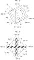
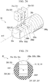
- Fig. 2 is a perspective view showing the sensor relating to the present embodiment.
- Fig. 3 is an end view showing the sensor relating to the present embodiment.
- Fig. 4 shows how the electrodes are arranged in the sensor relating to the present embodiment.
- the reference numeral 10 denotes the sensor.
- the senor 10 has a substantially cylindrical outer shape (shaped like a columnar body) around an axial line axd.
- the sensor 10 includes a first electrode 11, a second electrode 12, a third electrode 13, a fourth electrode 14 and an attracting portion (catching portion) 15.
- An end surface 10a of the sensor 10 has a substantially circular shape extending in the direction orthogonal to the axial line axd
- the first, second, third and fourth electrodes 11, 12, 13 and 14 each have a substantially fan-shaped sectional shape with a quadrant, when seen through the end surface 10a of the sensor 10.
- the first, second, third and fourth electrodes 11, 12, 13 and 14 all have substantially the same shape.
- the first, second, third and fourth electrodes 11, 12, 13 and 14 are arranged such that they are rotated around the axial line axd Accordingly, the first to fourth electrodes 11 to 14 are symmetrically arranged around the axial line axd.
- the electrodes 11 to 14 are arranged in the order of the first electrode 11, the second electrode 12, the fourth electrode 14, and the third electrode 13, clockwise in the circumferential direction rtd when seen through the end surface 10a.
- the first, second, fourth and third electrodes 11, 12, 14 and 13 are all at the same position in the direction along the axial line axd
- the first, second, fourth and third electrodes 11, 12, 14 and 13 are arranged such that their respective outer peripheral surfaces 11a to 14a form the same or flush cylindrical surface.
- the first, second, third and fourth electrodes 11, 12, 13 and 14 all have the same length in the direction along the axial line axd
- the first, second, third and fourth electrodes 11, 12, 13 and 14 are spaced away from each other in the direction extending in the end surface 10a. Gaps G1 to G4 are formed between the electrodes 11 to 14.
- the gap G1 denotes the spacing distance in the circumferential direction rtd between the first electrode 11 and the second electrode 12.
- the gap G2 denotes the spacing distance in the circumferential direction rtd between the first electrode 11 and the third electrode 13.
- the gap G3 denotes the spacing distance in the circumferential direction rtd between the second electrode 12 and the fourth electrode 14.
- the gap G4 denotes the spacing distance in the circumferential direction rtd between the third electrode 13 and the fourth electrode 14.
- the first, second, third and fourth electrodes 11, 12, 13 and 14 are all magnets.
- the magnets are, for example, permanent magnets.
- the first, second, third and fourth electrodes 11, 12, 13 and 14 are all magnetized in the radial direction of the sensor 10.
- the electrodes 11 to 14 are magnetized such that the adjacent ones of the electrodes 11 to 14 have different polarities.
- the second electrode 12 and the third electrode 13 are magnetized such that their respective outer peripheral surfaces 12a and 13a are the N pole.
- the first electrode 11 and the fourth electrode 14 are magnetized such that their respective outer peripheral surfaces 11a and 14a are the S pole.
- the direction of magnetization can be reversed in all of the electrodes 11 to 14.
- the electrodes 11 to 14 which are formed by magnets, are attracted to each other by their magnetic force.
- the electrodes 11 to 14 can be secured onto the cross-shaped attracting portion 15 without the use of an adhesive portion such as an adhesive agent.
- the attracting portion 15 is arranged between the electrodes 11 to 14, the attracting portion 15 is arranged.
- the attracting portion 15 is made of an insulating non-magnetic material, for example, resin.
- the attracting portion 15 has a section shaped like a cross when seen through the end surface 10a along the axial line axd
- the attracting portion 15 has an attracting protrusion 15G1 filling the gap G1 between the first electrode 11 and the second electrode 12 and protruding radially outward beyond the outer peripheral surfaces 11a, 12a.
- the attracting portion 15 has an attracting protrusion 15G2 filling the gap G2 between the first electrode 11 and the third electrode 13 and protruding radially outward beyond the outer peripheral surfaces 11a, 13a.
- the attracting portion 15 has an attracting protrusion 15G3 filling the gap G3 between the second electrode 12 and the fourth electrode 14 and protruding radially outward beyond the outer peripheral surfaces 12a, 14a.
- the attracting portion 15 has an attracting protrusion 15G4 filling the gap G4 between the third electrode 13 and the fourth electrode 14 and protruding radially outward beyond the outer peripheral surfaces 13a, 14a.
- the attracting protrusions 15G1 to 15G4 are formed such that they all have the same protruding height in the radial direction.
- the attracting protrusions 15G1 to 15G4 may be formed such that they have any, for example, different protruding heights in the radial direction.
- the size, in the circumferential direction rtd, of the gaps G1 to G4 between the electrodes 11 to 14 is larger than the size of the conductive substance that can be contained in the lubricating oil.
- the conductive substance has a size of approximately 1.0 ⁇ m to 100 ⁇ m.
- the gaps G1 to G4 are preferably arranged at such intervals that no short circuit is created by the iron powder resulting from initial wear period
- the gaps G1 to G4 all have the same size in the circumferential direction rtd
- magnetic flux lines run radially outside the attracting protrusions 15G1 to 15G4 to connect together the electrodes 11 to 14, as shown in Fig. 3 .
- magnetic flux lines start from the outer peripheral surface 12a of the second electrode 12, which is the N pole, run radially outside the attracting protrusion 15G1, and proceed toward the outer peripheral surface 11a of the first electrode 11, which is the S pole.
- magnetic flux lines start from the outer peripheral surface 13a of the third electrode 13, which is the N pole, run radially outside the attracting protrusion 15G2, and proceed toward the outer peripheral surface 11a of the first electrode 11, which is the S pole.
- magnetic flux lines start from the outer peripheral surface 12a of the second electrode 12, which is the N pole, run radially outside the attracting protrusion 15G3, and proceed toward the outer peripheral surface 14a of the fourth electrode 14, which is the S pole.
- magnetic flux lines start from the outer peripheral surface 13a of the third electrode 13, which is the N pole, run radially outside the attracting protrusion 15G4, and proceed toward the outer peripheral surface 14a of the fourth electrode 14, which is the S pole.
- the electrodes 11 to 14 can have a non-magnetic conductor portion at an end thereof opposite the end surface 10a. If such is the case, in the electrodes 11 to 14, the magnet and the conductor portion are in contact with each other so that the electrodes 11 to 14 are electrically conductive.
- Fig. 2 shows the conductor portion 12b of the second electrode 12.
- Output lines are connected to the first, second, third and fourth electrodes 11, 12, 13 and 14.
- the first, second, third and fourth electrodes 11, 12, 13 and 14 are respectively electrically connected to a sensing unit 5 (see Fig. 1 ) via the output lines.
- the electrodes 11 to 14 are insulated from each other.
- the first electrode 11 and one of the other electrodes 12 to 14 form a pair of electrodes, and the attracting portion 15 arranged between the paired electrodes constitutes a single detecting unit together with the pair of electrodes.
- the electrode pairs constituting the detecting units are denoted by assigning the sign "+" to the output line of the first electrode 11 and "-" to the output lines of the other electrodes 12 to 14.
- Fig. 5 is a sectional view showing how detection is performed in the sensor relating to the present embodiment.
- the sensor 10 includes three detecting units, corresponding to the second, third and fourth electrodes 12, 13 and 14. There are no particular limitations on the number of the electrodes 12 to 14 and the number of the detecting units. Since the electrodes 11 to 14 of the sensor 10, which are magnets, produce magnetic flux lines between the paired ones of the electrodes 11 to 14, the conductive particles (abrasion powder) mp contained in the lubricating oil are attracted to the attracting portion 15, as shown in Fig. 5 . Since the magnetic flux lines formed by the electrodes 11 to 14 start from the position immediately close to the attracting portion 15 and run radially, the conductive particles mp can be attracted highly efficiently. If the conductive particles mp are gathered in the vicinity of the attracting portion 15 in this manner, the detecting units experience a change in electrical resistance. While no conductive particles (abrasion powder) mp are attracted, the detecting units may exhibit the same electrical resistance.
- the detecting units corresponding to the second and third electrodes 12 and 13 are connected to each other in parallel Between the first electrode 11 and the second electrode 12, voltage is applied by the same voltage source. Between the first electrode 11 and the third electrode 13, voltage is applied by the same voltage source. If the conductive particles mp are gathered in the vicinity of the attracting protrusion 15G1, the detecting unit corresponding to the second electrode 12 experiences a change in electrical resistance. If the conductive particles mp are gathered in the vicinity of the attracting protrusion 15G2, the detecting unit corresponding to the third electrode 13 experiences a change in electrical resistance.
- the sensing unit 5 is configured to sense a change in electrical resistance between the first electrode 11 and the second electrode 12.
- the sensing unit 5 includes a sensor drive circuit for predicting a failure of the parts constituting the mechanism 1 based on, for example, a change in electrical resistance caused by the gathering of the conductive particles mp in the vicinity of the attracting protrusion 15G1. If the conductive particles mp contained in the lubricating oil are gathered in the vicinity of the attracting protrusion 15G1, this causes a drop in electrical resistance (or a short circuit) between the first electrode 11 and the second electrode 12 to which voltage is being applied, resulting in a change in output level of the output lines. The sensing unit 5 senses such a change in electrical resistance, thereby predicting a failure of the parts constituting the mechanism 1.
- the sensing unit 5 is configured to sense a change in electrical resistance between the first electrode 11 and the third electrode 13.
- the sensing unit 5 includes a sensor drive circuit for predicting a failure of the parts constituting the mechanism 1 based on, for example, a change in electrical resistance caused by the gathering of the conductive particles mp in the vicinity of the attracting protrusion 15G2. If the conductive particles mp contained in the lubricating oil are gathered in the vicinity of the attracting protrusion 15G3, this causes a drop in electrical resistance (or a short circuit) between the first electrode 11 and the third electrode 13 to which voltage is being applied, resulting in a change in output level of the output lines. The sensing unit 5 senses such a change in electrical resistance, thereby predicting a failure of the parts constituting the mechanism 1.
- the detecting unit corresponding to the fourth electrode 14 experiences a change in electrical resistance.
- the detecting unit corresponding to the fourth electrode 14 experiences a change in electrical resistance.
- the sensing unit 5 is configured to sense a change in electrical resistance between the first electrode 11 and the fourth electrode 14.
- the sensing unit 5 includes a sensor drive circuit for predicting a failure of the parts constituting the mechanism 1 based on, for example, a change in electrical resistance caused by the gathering of the conductive particles mp in the vicinity of the attracting protrusions 15G1 and 15G3. If the conductive particles mp contained in the lubricating oil are gathered in the vicinity of both of the attracting protrusions 15G1 and 15G3, this causes a drop in electrical resistance (or a short circuit) between the first electrode 11 and the fourth electrode 14 to which voltage is being applied, resulting in a change in output level of the output lines.
- the sensing unit 5 senses such a change in electrical resistance, thereby predicting a failure of the parts constituting the mechanism 1. This prediction is not made possible until the conductive particles mp are gathered in the vicinity of both of the attracting protrusions 15G1 and 15G3.
- the sensing unit 5 includes a sensor drive circuit for predicting a failure of the parts constituting the mechanism 1 based on, for example, a change in electrical resistance caused by the gathering of the conductive particles mp in the vicinity of the attracting protrusions 15G2 and 15G4. If the conductive particles mp contained in the lubricating oil are gathered in the vicinity of both of the attracting protrusions 15G2 and 15G4, this causes a drop in electrical resistance (or a short circuit) between the first electrode 11 and the fourth electrode 14 to which voltage is being applied, resulting in a change in output level of the output lines. The sensing unit 5 senses such a change in electrical resistance, thereby predicting a failure of the parts constituting the mechanism 1. This prediction is not made possible until the conductive particles mp are gathered in the vicinity of both of the attracting protrusions 15G2 and 15G4.
- the change in electrical resistance experienced by the detecting unit corresponding to the second electrode 12 and the detecting unit corresponding to the third electrode 13 is used to detect a change in electrical resistance in one attracting protrusion, which is selected from the attracting protrusions 15G1 and 15G2.
- the change in electrical resistance experienced by the detecting unit corresponding to the fourth electrode 14 is used to detect a change in electrical resistance in two attracting protrusions, which are either the attracting protrusions 15G1 and 15G3, or the attracting protrusions 15G2 and 15G4.
- the plurality of detecting units are capable of sensing different conditions.
- the detecting units are configured to detect a change in electrical resistance in two stages.
- the detecting units can perform the sensing in two stages and two systems. Accordingly, the reliability of the failure prediction can be improved
- the sensing unit 5 outputs a signal when a designated one of the detecting units experiences a change in electrical resistance.
- the sensing unit 5 may be configured to output a signal to a higher-level control device such as a manipulator when two or more of the detecting units experience a drop in electrical resistance, or configured to output a signal when all of the detecting units experience a drop in electrical resistance.
- the drop in electrical resistance may be indicated by an ON signal and an OFF signal corresponding to electrical disconnection and connection.
- the sensing unit 5 may sense two states of electrical disconnection and connection (hereinafter, may be referred to as "perform digital sensing").
- the sensing unit 5 may be connected to a higher-level control device (not shown) such as a manipulator in a wired or wireless manner.
- the higher-level control device may be configured to, upon reception of a signal from the sensing unit 5, issue an alert for demanding maintenance of, for example, the speed reducer 2 with a predetermined notifying device (for example, a display or voice output device).
- the senor 10 of the present embodiment includes the plurality of detecting units, and the sensing unit 5 outputs a signal when designated one or more of the detecting units experience a drop in electrical resistance.
- the sensing unit 5 can be configured to output no signal when just one of the detecting units experiences a change in electrical resistance caused by initial abrasion powder but the other detecting units do not experience a change in electrical resistance. Accordingly, the sensor can be prevented from operating unexpectedly.
- the sensing unit 5 can be configured to output a signal under a designated condition. Therefore, the single sensor 10 can be configured to output a signal in a timely and optimal manner for individual users, who have different requests for failure prediction timing.
- the detecting units can exhibit the same electrical resistance. This can lower the voltage to be applied to the sensor 10.
- the detecting units are connected in parallel to each other. This can lower the voltage applied between the paired electrodes in each detecting unit.
- the sensor 10 is preferably positioned such that the first electrode 11, which forms the detecting unit with every one of the other electrodes 12 to 14, deals with a large amount of conductive particles mp.
- the gaps G1 to G4 for detecting the conductive particles mp are arranged next to each other in the circumferential direction rtd along the outer peripheral surfaces 11a to 14a.
- the sensor 10 can be reduced in size without compromising the detection sensitivity.
- the direction of the detection performed by the detecting units can be configured to extend in the circumferential direction rtd along the outer peripheral surfaces 11a to 14a.
- the senor 10 when compared with the case where a plurality of detection gaps extending in the axial line axd direction are arranged next to each other in the circumferential direction of the sensor, the sensor 10 can be reduced in size without compromising the detection sensitivity. Furthermore, since the magnetic flux lines produced by the electrodes 11 to 14, which are magnets, start from the position immediately close to the attracting portion 15 and run radially, the conductive particles mp can be attracted highly efficiently. Thus, the size reduction can not result in lower attraction efficiency. Furthermore, the sensor 10 of the present embodiment can be constituted by a reduced number of parts, assembled easily and manufactured at a reduced cost.
- Figs. 6A and 6B show another example of the magnets included in the sensor relating to the present embodiment.
- the magnets forming the electrodes 11 to 14 have a section shaped like a fan. As shown in Figs. 6A and 6B , however, the magnets forming the electrodes 11 to 14 can have a section shaped like a circumferential quarter of a ring. In this case, all of the electrodes 11 to 14 also have a direction of magnetization extending in the radial direction of the sensor 10.
- the second electrode 12 and the third electrode 13 are magnetized such that their respective outer peripheral surfaces 11a and 12a are like poles.
- the first electrode 11 and the fourth electrode 14 are magnetized such that their respective outer peripheral surfaces 11a and 14a are like poles.
- the electrodes 11 to 14 are magnetized such that the adjacent ones of the electrodes 11 to 14 are different poles.
- the electrodes 11 to 14 which are formed by magnets, are attracted to each other by their magnetic force.
- the electrodes 11 to 14 can be secured onto the cross-shaped attracting portion 15 without the use of an adhesive portion such as an adhesive agent.
- Fig. 7 is a perspective view showing another example of the sensor relating to the present embodiment.
- the output lines extending from the electrodes 11 to 14 can be formed by using flexible substrates 11f to 14f, as shown in Fig. 7 .
- the output line connected to the first electrode 11 is formed by the flexible substrate 11f, which is interposed between the first electrode 11 and the attracting portion 15.
- a portion of the flexible substrate 11f that is in contact with the first electrode 11 is electrically conductive as, for example, coating has been removed and thus in electrical communication with the first electrode 11.
- the electrodes 11 to 14, which are formed by magnets are attracted to each other due to their magnetic force, the flexible substrate 11f is secured while being sandwiched between the first electrode 11 and the attracting portion 15.
- the flexible substrate 11f can be fixedly connected to the first electrode 11 without the use of an adhesive agent or the like and with the electrical connection being maintained
- the flexible substrate 12f is fixedly connected to the second electrode 12
- the flexible substrate 13f is fixedly connected to the third electrode 13
- the flexible substrate 14f is fixedly connected to the fourth electrode 14.
- Fig. 7 shows that the flexible substrate 11f is interposed between the first electrode 11 and the attracting protrusion 15G2, but the flexible substrate 11f can be alternatively interposed between the first electrode 11 and the attracting protrusion 15G1.
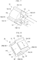
- Fig. 8 is a perspective view showing the sensor relating to the present embodiment.
- Fig. 9 is an end view showing the sensor relating to the present embodiment.
- the reference numeral 20 denotes the sensor.
- the second embodiment is different from the above-described first embodiment in terms of the outer shape of the sensor and magnets. The constituents of the mechanism 1 illustrated in Fig. 1 are not described here.
- the sensor 20 has a substantially prismatic outer shape (shaped like a column) around an axial line axd
- the sensor 20 includes a first electrode 21, a second electrode 22, a third electrode 23, a fourth electrode 24 and an attracting portion (catching portion) 25.
- An end surface 20a of the sensor 20 has a substantially rectangular shape extending in the direction orthogonal to the axial line axd
- the first, second, third and fourth electrodes 21, 22, 23 and 24 form side surfaces of a prism.
- the first, second, third and fourth electrodes 21, 22, 23 and 24 have a section substantially shaped like a rectangle, when seen through the end surface 20a of the sensor 20.
- the electrodes 21 to 24 are shaped like a rectangular flat plate.
- the first, second, third and fourth electrodes 21, 22, 23 and 24 all have substantially the same shape.
- the first, second, third and fourth electrodes 21, 22, 23 and 24 are arranged such that they are rotated around the axial line axd Accordingly, the first to fourth electrodes 21 to 24 are symmetrically arranged around the axial line axd.
- the electrodes 21 to 24 are arranged in the order of the first electrode 21, the second electrode 22, the fourth electrode 24, and the third electrode 23, clockwise in the circumferential direction rtd when seen through the end surface 20a.
- the first, second, fourth and third electrodes 21, 22, 24 and 23 are all at the same position in the direction along the axial line axd
- the first, second, fourth and third electrodes 21, 22, 24 and 23 are arranged such that their respective outer peripheral surfaces 21a to 24a are at the same distance from the axial line axd and form the sides of square section.
- the first, second, third and fourth electrodes 21, 22, 23 and 24 all have the same length in the direction along the axial line axd
- the first, second, third and fourth electrodes 21, 22, 23 and 24 are spaced away from each other in the direction extending in the end surface 20a. Gaps G1 to G4 are formed between the electrodes 21 to 24.
- the gap G1 denotes the spacing distance in the circumferential direction rtd between the first electrode 21 and the second electrode 22.
- the gap G2 denotes the spacing distance in the circumferential direction rtd between the first electrode 21 and the third electrode 23.
- the gap G3 denotes the spacing distance in the circumferential direction rtd between the second electrode 22 and the fourth electrode 24.
- the gap G4 denotes the spacing distance in the circumferential direction rtd between the third electrode 23 and the fourth electrode 24.
- the first, second, third and fourth electrodes 21, 22, 23 and 24 are all magnets.
- the magnets are, for example, permanent magnets.
- the direction of magnetization extends in the radial direction of the sensor 20.
- the electrodes 21 to 24 are thin plate-shaped magnets magnetized such that the front surface, which is the principal surface of the plate, and the back surface are different poles.
- the first electrode 21 and the fourth electrode 24, which are symmetrically positioned with respect to the axial line axd and oppose each other, are magnetized such that their respective outer peripheral surfaces 21a and 24a are like poles.
- the second electrode 22 and the third electrode 23, which are symmetrically positioned with respect to the axial line axd and oppose each other, are magnetized such that their respective outer peripheral surfaces 22a and 23a are like poles.
- the electrodes 21 to 24 are magnetized such that the adjacent ones of the electrodes 21 to 24 are different poles.
- the second electrode 22 and the third electrode 23 are magnetized such that their respective outer peripheral surfaces 22a and 23a are N poles.
- the first electrode 21 and the fourth electrode 24 are magnetized such that their respective outer peripheral surfaces 21a and 24a are S poles.
- the direction of magnetization can be reversed in all of the electrodes 21 to 24.
- the electrodes 21 to 24, which are magnets are arranged such that the N-pole surfaces are opposed and parallel to each other and the S-pole surfaces are opposed and parallel to each other. Accordingly, the electrodes 21 to 24 are attracted to each other by their magnetic force. As a result, the electrodes 21 to 24, which are magnets, can be secured onto a center portion 25c of the cross-shaped attracting portion 25 without the use of an adhesive portion such as an adhesive agent.
- the attracting portion 25 is arranged between the electrodes 21 to 24, the attracting portion 25 is arranged.
- the attracting portion 25 is made of an insulating non-magnetic material, for example, resin.
- the attracting portion 25 has a section shaped like a cross when seen through the end surface 20a along the axial line axd, and, in the attracting portion 25, the center portion 25c is larger than the radial end
- the center portion 25c is shaped like a prism.
- the center portion 25c fills the space between the electrodes 21 to 24.
- the attracting portion 25 has an attracting protrusion 25G1 filling the gap G1 between the first electrode 21 and the second electrode 22 and protruding radially outward beyond the outer peripheral surfaces 21a, 22a.
- the attracting portion 25 has an attracting protrusion 25G2 filling the gap G2 between the first electrode 21 and the third electrode 23 and protruding radially outward beyond the outer peripheral surfaces 21a, 23a.
- the attracting portion 25 has an attracting protrusion 25G3 filling the gap G3 between the second electrode 22 and the fourth electrode 24 and protruding radially outward beyond the outer peripheral surfaces 22a, 24a.
- the attracting portion 25 has an attracting protrusion 25G4 filling the gap G4 between the third electrode 23 and the fourth electrode 24 and protruding radially outward beyond the outer peripheral surfaces 23a, 24a.
- the attracting protrusions 25G1 to 25G4 are shaped as radially outward extensions of the diagonals of the rectangle (square) formed by the electrodes 21 to 24.
- the attracting protrusions 25G1 to 25G4 are formed such that they all have the same protruding height in the radial direction.
- the attracting protrusions 25G1 to 25G4 may be formed such that they have any, for example, different protruding heights in the radial direction.
- the size, in the circumferential direction rtd, of the gaps G1 to G4 between the electrodes 21 to 24 is larger than the size of the conductive substance that can be contained in the lubricating oil.
- the conductive substance has a size of approximately 1.0 ⁇ m to 100 ⁇ m.
- the gaps G1 to G4 are preferably arranged at such intervals that no short circuit is created by the iron powder resulting from initial wear period
- the gaps G1 to G4 all have the same size in the circumferential direction rtd
- magnetic flux lines run radially outside the attracting protrusions 25G1 to 25G4 to connect the electrodes 21 to 24, as shown in Fig. 9 .
- magnetic flux lines start from the outer peripheral surface 21a of the second electrode 22, which is the N pole, run radially outside the attracting protrusion 25G1, and proceed toward the outer peripheral surface 21a of the first electrode 21, which is the S pole.
- magnetic flux lines start from the outer peripheral surface 23a of the third electrode 23, which is the N pole, run radially outside the attracting protrusion 25G2, and proceed toward the outer peripheral surface 21a of the first electrode 23, which is the S pole.
- magnetic flux lines start from the outer peripheral surface 22a of the second electrode 22, which is the N pole, run radially outside the attracting protrusion 25G3, and proceed toward the outer peripheral surface 24a of the fourth electrode 24, which is the S pole.
- magnetic flux lines start from the outer peripheral surface 23a of the third electrode 23, which is the N pole, run radially outside the attracting protrusion 25G4, and proceed toward the outer peripheral surface 24a of the fourth electrode 24, which is the S pole.
- the electrodes 21 to 24 do not need to be in contact with the attracting protrusions 25G1 to 25G4. As shown in Fig. 9 , as moving outward radially from the center portion 25c, the spacing distance between the electrodes 21 to 24 and the attracting protrusions 25G1 to 25G4 may increase.
- the electrodes 21 to 24 can have a non-magnetic conductor portion at a position opposite the end surface 20a. If such is the case, in the electrodes 21 to 24, the magnet and the conductor portion are in contact with each other so that the electrodes 21 to 24 are electrically conductive.
- Output lines are connected to the first, second, third and fourth electrodes 21, 22, 23 and 24.
- the first, second, third and fourth electrodes 21, 22, 23 and 24 are respectively electrically connected to the sensing unit 5 (see Fig. 1 as mentioned in the first embodiment) via the output lines.
- the electrodes 21 to 24 are insulated from each other.
- the first electrode 21 and one of the other electrodes 22 to 24 form a pair of electrodes, and the attracting portion 25 arranged between the paired electrodes constitutes a single detecting unit together with the pair of electrodes.
- the senor 20 includes three detecting units, corresponding to the second, third and fourth electrodes 22, 23 and 24. There are no particular limitations on the number of the electrodes 22 to 24 and the number of the detecting units. Since the electrodes 21 to 24 of the sensor 20, which are magnets, produce magnetic flux lines between the paired ones of the electrodes 21 to 24, the abrasion powder mp (see Fig. 5 mentioned in the first embodiment) contained in the lubricating oil are attracted by the attracting portion 25. If the conductive particles mp are gathered in the vicinity of the attracting portion 25 in this manner, the detecting units experience a change in electrical resistance. While no conductive particles (abrasion powder) mp are attracted, the detecting units may all exhibit the same electrical resistance.
- the detecting units are electrically connected to the sensing unit 5.
- the detecting units corresponding to the second and third electrodes 22 and 23 are connected to each other in parallel Between the first electrode 21 and the second electrode 22, voltage is applied by the same voltage source. Between the first electrode 21 and the third electrode 23, voltage is applied by the same voltage source. If the conductive particles mp are gathered in the vicinity of the attracting protrusion 25G1, the detecting unit corresponding to the second electrode 22 experiences a change in electrical resistance. If the conductive particles mp are gathered in the vicinity of the attracting protrusion 25G2, the detecting unit corresponding to the third electrode 23 experiences a change in electrical resistance.
- the sensing unit 5 is configured to sense a change in electrical resistance between the first electrode 21 and the second electrode 22.
- the sensing unit 5 includes a sensor drive circuit for predicting a failure of the parts constituting the mechanism 1 based on, for example, a change in electrical resistance caused by the gathering of the conductive particles mp in the vicinity of the attracting protrusion 25G1. If the conductive particles mp contained in the lubricating oil are gathered in the vicinity of the attracting protrusion 25G1, this causes a drop in electrical resistance (or a short circuit) between the first electrode 21 and the second electrode 22 to which voltage is being applied, resulting in a change in output level of the output lines. The sensing unit 5 senses such a change in electrical resistance, thereby predicting a failure of the parts constituting the mechanism 1.
- the sensing unit 5 is configured to sense a change in electrical resistance between the first electrode 21 and the third electrode 23.
- the sensing unit 5 includes a sensor drive circuit for predicting a failure of the parts constituting the mechanism 1 based on, for example, a change in electrical resistance caused by the gathering of the conductive particles mp in the vicinity of the attracting protrusion 25G2. If the conductive particles mp contained in the lubricating oil are gathered in the vicinity of the attracting protrusion 25G3, this causes a drop in electrical resistance (or a short circuit) between the first electrode 21 and the third electrode 23 to which voltage is being applied, resulting in a change in output level of the output lines. The sensing unit 5 senses such a change in electrical resistance, thereby predicting a failure of the parts constituting the mechanism 1.
- the detecting unit corresponding to the fourth electrode 24 experiences a change in electrical resistance. If the conductive substance is gathered in the vicinity of both of the attracting protrusions 25G2 and 25G4, the detecting unit corresponding to the fourth electrode 24 experiences a change in electrical resistance.
- the sensing unit 5 is configured to sense a change in electrical resistance between the first electrode 21 and the fourth electrode 24.
- the sensing unit 5 includes a sensor drive circuit for predicting a failure of the parts constituting the mechanism 1 based on, for example, a change in electrical resistance caused by the gathering of the conductive particles mp in the vicinity of the attracting protrusions 25G1 and 25G3. If the conductive particles mp contained in the lubricating oil are gathered in the vicinity of both of the attracting protrusions 25G1 and 25G3, this causes a drop in electrical resistance (or a short circuit) between the first electrode 21 and the fourth electrode 24 to which voltage is being applied, resulting in a change in output level of the output lines.
- the sensing unit 5 senses such a change in electrical resistance, thereby predicting a failure of the parts constituting the mechanism 1. This sensing is not made possible until the conductive particles mp are gathered in the vicinity of both of the attracting protrusions 25G1 and 25G3.
- the sensing unit 5 includes a sensor drive circuit for predicting a failure of the parts constituting the mechanism 1 based on, for example, a change in electrical resistance caused by the gathering of the conductive particles mp in the vicinity of the attracting protrusions 25G2 and 25G4. If the conductive particles mp contained in the lubricating oil are gathered in the vicinity of both of the attracting protrusions 25G2 and 25G4, this causes a drop in electrical resistance (or a short circuit) between the first electrode 21 and the fourth electrode 24 to which voltage is being applied, resulting in a change in output level of the output lines. The sensing unit 5 senses such a change in electrical resistance, thereby predicting a failure of the parts constituting the mechanism 1. This sensing is not made possible until the conductive particles mp are gathered in the vicinity of both of the attracting protrusions 25G2 and 25G4.
- the change in electrical resistance experienced by the detecting unit corresponding to the second electrode 22 and the detecting unit corresponding to the third electrode 23 is used to detect a change in electrical resistance in one attracting protrusion, which is selected from the attracting protrusions 25G1 and 25G2.
- the change in electrical resistance experienced by the detecting unit corresponding to the fourth electrode 24 is used to detect the change in electrical resistance in two attracting protrusions, which are either the attracting protrusions 25G1 and 25G3 or attracting protrusions 25G2 and 25G4.
- the plurality of detecting units are capable of sensing different conditions.
- the detecting units are configured to detect a change in electrical resistance in two stages.
- the detecting units can perform the sensing in two stages and two systems. Accordingly, the reliability of the failure prediction can be improved
- the sensing unit 5 outputs a signal when a designated one of the detecting units experiences a change in electrical resistance.
- the sensing unit 5 may be configured to output a signal to a higher-level control device such as a manipulator when two of the detecting units, more specifically, the detecting unit corresponding to the second electrode 22 and the detecting unit corresponding to the third electrode 23 experience a drop in electrical resistance.
- the sensing unit 5 may be alternatively configured to output a signal when all of the detecting units including the detecting unit corresponding to the fourth electrode 24 experience a drop in electrical resistance.
- the drop in electrical resistance may be indicated by an ON signal and an OFF signal corresponding to electrical disconnection and connection.
- the sensing unit 5 may sense two states of electrical disconnection and connection (hereinafter, may be referred to as "perform digital sensing").
- the sensing unit 5 may be connected to a higher-level control device (not shown) such as a manipulator in a wired or wireless manner.
- the higher-level control device may be configured to, upon reception of a signal from the sensing unit 5, issue an alert for demanding maintenance of, for example, the speed reducer 2 with a predetermined notifying device (for example, a display or voice output device).
- the sensor 20 of the present embodiment includes the plurality of detecting units, and the sensing unit 5 outputs a signal when designated one or more of detecting units experience a drop in electrical resistance.
- the sensing unit 5 can be configured to output no signal when just one of the detecting units experiences a change in electrical resistance caused by initial abrasion powder but the other detecting units do not experience a change in electrical resistance. Accordingly, the sensor can be prevented from operating unexpectedly.
- the sensing unit 5 can be configured to output a signal under a designated condition. Therefore, the single sensor 20 can be configured to output a signal in a timely and optimal manner for individual users, who have different requests for failure prediction timing.
- the detecting units can exhibit the same electrical resistance. This can lower the voltage to be applied to the sensor 20.
- the detecting units are connected in parallel to each other. This can lower the voltage applied between the paired electrodes in each detecting unit.
- the sensor 20 is preferably positioned such that the first electrode 21, which forms the detecting unit with all of the other electrodes 22 to 24, deals with a large amount of conductive particles mp.
- the gaps G1 to G4 for detecting the conductive particles mp are arranged next to each other in the circumferential direction rtd along the outer peripheral surfaces 21a to 24a.
- the sensor 20 can be reduced in size without compromising the detection sensitivity.
- the direction of the detection performed by the detecting units can be configured to extend in the circumferential direction rtd along the outer peripheral surfaces 21a to 24a.
- the senor 20 when compared with the case where a plurality of detection gaps extending in the axial line axd are arranged next to each other in the circumferential direction of the sensor, the sensor 20 can be reduced in size without compromising the detection sensitivity. Since the magnetic flux lines produced by the electrodes 21 to 24, which are magnets, start from the position immediately close to the attracting portion 25 and run radially, the conductive particles mp can be attracted highly efficiently. Thus, the size reduction can not result in lower attraction efficiency. As a result, the size reduction can carry on. Furthermore, the sensor 20 of the present embodiment can be constituted by a reduced number of parts, assembled easily and manufactured at a reduced cost as reasonable plate-shaped magnets are employed
- Fig. 10 shows a section orthogonal to the axial direction in order to illustrate another example of the sensor relating to the present embodiment.
- the magnets forming the electrodes 21 to 24 are partly spaced away from the attracting protrusions 25G1 to 25G4.
- grooves 25m may be provided in the bases of the attracting protrusions 25G1 to 25G4 and the center portion 25c for receiving the magnets forming the electrodes 21 to 24.
- the grooves 25m preferably do not cover the outer peripheral surfaces 21a to 24a of the electrodes 21 to 24.
- the same amount of conductive particles mp can preferably gather, which is determined by the total length in the circumferential direction rtd of the attracting protrusions 25G1 to 25G4, namely, in the example case of the attracting protrusion 25G1, the surface distance from the adjacent outer peripheral surface 21a to the outer peripheral surface 22a.
- the detection sensitivity of each detecting unit can be designated independent from whether there are the grooves 25m.
- the size in the circumferential direction rtd of the gaps G1 to G4 preferably remains the same.
- the senor 20 can be easily assembled by inserting into the grooves 25m the electrodes 21 to 24 along the axial line axd direction from the end surface 20a side. With this configuration, the electrodes 21 to 24 can be more rigidly secured than when the electrodes 21 to 24 are secured onto the attracting portion 25 only through the magnetic force of the electrodes 21 to 24.
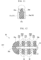
- Fig. 11 shows a section along the axial direction in order to illustrate another example of the sensor relating to the present embodiment.
- the electrodes 21 to 24 and the attracting portion 25 are flush with each other on the end surface 20a.
- an end surface 20d can be formed as an inclined surface the central portion of which protrudes outward in the axial line axd direction and electrodes 26a to 26d, which are magnets, can be provided.
- the electrodes 26a to 26d and electrodes 21 to 24 are also arranged such that adjacent ones of the magnets are different poles.
- the output lines extending from the electrodes 21 to 24 can be also formed by using the flexible substrates 11f to 14f, as shown in Fig. 7 mentioned in the first embodiment.
- the electrodes 21 to 24, which are magnets, are arranged such that the N-pole surface is opposed and parallel to the S-pole surface. Accordingly, the flexible substrates 11f to 14f are pressed against the attracting portion 25 with stronger force than in the first embodiment. This can in turn allow the flexible substrates 11f to 14f to be more rigidly secured and contribute to maintain excellent contact.
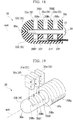
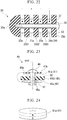
- Fig. 12 is a sectional view taken along the axial direction and showing the sensor relating to the third embodiment of the present invention.
- Fig. 13 is used to illustrate the magnets of the sensor relating to the present embodiment.
- the reference numeral 30 denotes the sensor.
- the third embodiment is different from the above-described first embodiment in terms of the configurations of the sensor. The constituents of the mechanism 1 illustrated in Fig. 1 are not described here.
- the sensor 30 has a substantially cylindrical outer shape around an axial line axd
- the sensor 30 includes a first electrode 31, a second electrode 32, a third electrode 33, and an attracting portion (catching portion) 35.
- a front end 30a of the sensor 30 is substantially shaped like a hemisphere.
- the first, second and third electrodes 31, 32 and 33 are plate members having a circular outline centered around the axial line axd when seen in the axial line axd direction.
- the first, second and third electrodes 31, 32 and 33 all have substantially the same outline and substantially the same thickness.
- the second electrode 32, the first electrode 31 and the third electrode 33 are stacked in the axial line axd direction in the stated order from the front end 30a toward the base end along the axial line axd direction.
- the second electrode 32, first electrode 31 and third electrode 33 are arranged next to each other in the direction along the axial line axd and parallel to each other concentrically.
- the second electrode 32, first electrode 31 and third electrode 33 are arranged such that their respective outer peripheral surfaces 31a to 33a form the same or flush cylindrical surface.
- the second electrode 32, first electrode 31 and third electrode 33 all have the same radial size in the direction orthogonal to the axial line axd
- the second electrode 32, first electrode 31 and third electrode 33 are spaced away from each other in the direction along the axial line axd Gaps G1 and G2 are formed between the electrodes 31 to 33.
- the gap G1 denotes the spacing distance in the direction along the axial line axd between the first electrode 31 and the second electrode 32.
- the gap G2 denotes the spacing distance in the direction along the axial line axd between the first electrode 31 and the third electrode 33.
- the first, second and third electrodes 31, 32 and 33 are all magnets.
- the magnets are, for example, permanent magnets.
- the direction of magnetization extends in the radial direction of the sensor 30.
- the first electrode 31 is magnetized such that the halves of the radially outer peripheral surface 31a are different poles.
- the second and third electrodes 32 and 33 are both magnetized such that the halves of their respective outer peripheral surfaces 32a and 33a are different poles.
- the poles of the outer peripheral surface 31a of the first electrode 31 are opposite to the poles of the outer peripheral surfaces 32a and 33a of the second and third electrodes 32 and 33.
- the electrodes 31, 32, 33 which are adjacent to each other along the axial line axd, are magnetized such that different poles are adjacent. That is to say, the first electrode 31 is a magnet magnetized in the same manner as the second and third electrodes 32 and 33 but rotated around the axial line axd by 180°.
- the first electrode 31 is magnetized such that the lower half of the outer peripheral surface 31a is the N pole.
- the second and third electrodes 32 and 33 are magnetized such that the upper half of their respective outer peripheral surfaces 32a and 33a is the N pole.
- the direction of magnetization can be reversed in all of the electrodes 31 to 33.
- the electrodes 31 to 33 which are magnets, are attracted to each other in the axial line axd direction by their magnetic force.
- the electrodes 31 to 33 can be arranged to overlap each other in the axial line axd direction and secured onto the attracting portion 25 without the use of an adhesive portion such as an adhesive agent.
- the attracting portion 35 is made of an insulating non-magnetic material, for example, resin.
- the attracting portion 35 is a plate-shaped member having a circular outline when seen along the axial line axd from the side of the front end 30a.
- the attracting portion 35 has an attracting protrusion 35G1 filling the gap G1 between the first electrode 31 and the second electrode 32 and protruding radially outward beyond the outer peripheral surfaces 31a, 32a.
- the attracting portion 35 has an attracting protrusion 35G2 filling the gap G2 between the first electrode 31 and the third electrode 33 and protruding radially outward beyond the outer peripheral surfaces 31a, 33a.
- the attracting protrusions 35G1 and 35G2 are formed such that they both have the same protruding height beyond the outer peripheral surfaces 31a to 33a in the radial direction.
- the attracting protrusions 35G1, 35G2 may be formed such that they have any, for example, different protruding heights in the radial direction.
- the thickness, in the axial line axd direction, of the gaps G1 and G2 between the electrodes 31 to 33 is larger than the size of the conductive substance that can be contained in the lubricating oil.
- the conductive substance has a size of approximately 1.0 ⁇ m to 100 ⁇ m.
- the gaps G1 and G2 are preferably arranged at such intervals that no short circuit is created by the iron powder resulting from initial wear period
- the gaps G1 and G2 have the same size in the direction along the axial line axd
- Electro flux lines run radially outside the attracting protrusions 35G1, 35G2 to connect the electrodes 31 to 33 in the direction along the axial line axd, as shown in Fig. 12 .
- magnetic flux lines start from the outer peripheral surface 31a of the first electrode 31, which is the N pole, run radially outside the attracting protrusion 35G1, and proceed toward the outer peripheral surface 32a of the second electrode 32, which is the S pole.
- magnetic flux lines start from the outer peripheral surface 32a of the second electrode 32, which is the N pole, run radially outside the attracting protrusion 35G1, and proceed toward the outer peripheral surface 31a of the first electrode 31, which is the S pole.
- magnetic flux lines start from the outer peripheral surface 31a of the first electrode 31, which is the N pole, run radially outside the attracting protrusion 35G2, and proceed toward the outer peripheral surface 33a of the third electrode 33, which is the S pole.
- magnetic flux lines start from the outer peripheral surface 33a of the third electrode 33, which is the N pole, run radially outside the attracting protrusion 35G2, and proceed toward the outer peripheral surface 31a of the first electrode 31, which is the S pole.
- a front end portion 35a made of the same material as the attracting portion 35 is formed
- the front end portion 35a has the same outline as the attracting protrusions 35G1, 35G2 when seen in the direction along the axial line axd
- the front end portion 35a has a spherical surface.
- a base end portion 35b made of the same material as the attracting portion 35 is formed
- the base end portion 35b has the same outline as the attracting protrusions 35G1, 35G2 when seen in the direction along the axial line axd.
- the base end portion 35b has the same thickness as the attracting protrusions 35G1, 35G2 in the direction along the axial line axd
- the fastening member 38 is inserted through the center holes centered around the axial line axd, so that the electrodes 31 to 33, the attracting protrusions 35G1, 35G2, the front end portion 35a and the base end portion 35b are secured to each other.
- a tube 37 is provided radially outside the screw 38 and surrounds the screw 38.
- the tube 37 contributes to keep the electrodes 31 to 33 and the screw 38 insulated from each other and to secure the electrodes 31 to 33 and attracting protrusions 35G1, 35G2 relative to the front and base end portions 35a, 35b at predetermined positions in the radial direction.
- Output lines are connected to the first, second and third electrodes 31, 32 and 33.
- the first, second and third electrodes 31, 32 and 33 are respectively electrically connected to the sensing unit 5 (see Fig. 1 ) via the output lines.
- the electrodes 31 to 33 are insulated from each other.
- the first electrode 31 and one of the other electrodes 32 to 33 form a pair of electrodes, and the attracting portion 35 arranged between the paired electrodes constitutes a single detecting unit together with the pair of electrodes.
- the electrode pairs constituting the detecting units are denoted by assigning the sign "+" to the output line of the first electrode 31 and "-" to the output lines of the other electrodes 32, 33.
- Fig. 15 is a sectional view showing how detection is performed in the sensor relating to the present embodiment.
- the sensor 30 includes two detecting units, corresponding to the second and third electrodes 32, 23.
- the detecting units corresponding to the second and third electrodes 32 and 33 are connected to each other in parallel Between the first electrode 31 and the second electrode 32, voltage is applied by the same voltage source. Between the first electrode 31 and the third electrode 33, voltage is applied by the same voltage source. If the conductive particles mp are gathered in the vicinity of the attracting protrusion 35G1, the detecting unit corresponding to the second electrode 32 experiences a change in electrical resistance. If the conductive particles mp are gathered in the vicinity of the attracting protrusion 35G2, the detecting unit corresponding to the third electrode 33 experiences a change in electrical resistance.
- the sensing unit 5 is configured to sense a change in electrical resistance between the first electrode 31 and the second electrode 32.
- the sensing unit 5 includes a sensor drive circuit for predicting a failure of the parts constituting the mechanism 1 based on, for example, a change in electrical resistance caused by the gathering of the conductive particles mp in the vicinity of the attracting protrusion 35G1. If the conductive particles mp contained in the lubricating oil are gathered in the vicinity of the attracting protrusion 35G1, this causes a drop in electrical resistance (or a short circuit) between the first electrode 31 and the second electrode 32 to which voltage is being applied, resulting in a change in output level of the output lines. The sensing unit 5 senses such a change in electrical resistance, thereby predicting a failure of the parts constituting the mechanism 1.
- the sensing unit 5 is configured to sense a change in electrical resistance between the first electrode 31 and the third electrode 33.
- the sensing unit 5 includes a sensor drive circuit for predicting a failure of the parts constituting the mechanism 1 based on, for example, a change in electrical resistance caused by the gathering of the conductive particles mp in the vicinity of the attracting protrusion 35G2. If the conductive particles mp contained in the lubricating oil are gathered in the vicinity of the attracting protrusion 35G2, this causes a drop in electrical resistance (or a short circuit) between the first electrode 31 and the third electrode 33 to which voltage is being applied, resulting in a change in output level of the output lines. The sensing unit 5 senses such a change in electrical resistance, thereby predicting a failure of the parts constituting the mechanism 1.
- the change in electrical resistance experienced by the detecting unit corresponding to the second electrode 32 and the detecting unit corresponding to the third electrode 33 is used to detect a change in electrical resistance in one attracting protrusion, which is selected from the attracting protrusions 35G1 and 35G2.
- the plurality of detecting units are capable of sensing different conditions.
- the detecting units are configured to detect a change in electrical resistance in two systems.
- the sensing unit 5 outputs a signal when designated one or more of the detecting units experiences a change in electrical resistance.
- the sensing unit 5 may be configured to output a signal to a higher-level control device such as a manipulator when two or more of the detecting units experience a drop in electrical resistance, or configured to output a signal when all of the detecting units experience a drop in electrical resistance.
- the drop in electrical resistance may be indicated by an ON signal and an OFF signal corresponding to electrical disconnection and connection.
- the sensing unit 5 may sense two states of electrical disconnection and connection (hereinafter, may be referred to as "perform digital sensing").
- the sensing unit 5 may be connected to a higher-level control device (not shown) such as a manipulator in a wired or wireless manner.
- the higher-level control device may be configured to, upon reception of a signal from the sensing unit 5, issue an alert for demanding maintenance of, for example, the speed reducer 2 with a predetermined notifying device (for example, a display or voice output device).
- the senor 30 of the present embodiment includes the plurality of detecting units, and the sensing unit 5 outputs a signal when designated one or more of the detecting units experience a drop in electrical resistance.
- the sensing unit 5 can be configured to output no signal when just one of the detecting units experiences a change in electrical resistance caused by initial abrasion powder but the other detecting units do not experience a change in electrical resistance. Accordingly, the sensor can be prevented from operating unexpectedly.
- the sensing unit 5 can be configured to output a signal under a designated condition. Therefore, the single sensor 30 can be configured to output a signal in a timely and optimal manner for individual users, who have different requests for failure prediction timing.
- the detecting units can exhibit the same electrical resistance. This can lower the voltage to be applied to the sensor 30.
- the detecting units are connected in parallel to each other. This can lower the voltage applied between the paired electrodes in each detecting unit.
- the sensor 30 is preferably positioned such that the first electrode 31, which forms the detecting unit with every one of the other electrodes 32, 33, deals with a large amount of conductive particles mp.
- the gaps G1, G2 for detecting the conductive particles mp extend along the outer peripheral surfaces 31a to 33a and are arranged next to each other in the direction along the axial line axd In this way, when compared with the case where such gaps for detecting conductive particles are arranged next to each other in the radial direction on the end surface of the sensor 30, the sensor 30 can be reduced in size without compromising the detection sensitivity.
- the detecting units extending along the outer peripheral surfaces 31a to 33a can be adjacent to each other in the direction along the axial line axd and the direction of the detection can be configured to extend in the direction along the axial line axd Accordingly, when compared with the case where a plurality of detection gaps extending in the axial line axd direction are arranged next to each other in the circumferential direction of the sensor, the sensor can be reduced in size without compromising the detection sensitivity. Since the magnets are exposed on the surface of the sensor, the magnets also serve as the electrodes 31 to 33, and the magnetic flux lines start from the position immediately close to the attracting portion 35 and run radially, the conductive particles mp can be attracted highly efficiently. Thus, the size reduction can not result in lower attraction efficiency. Furthermore, the sensor 30 of the present embodiment can be constituted by a reduced number of parts, assembled easily and manufactured at a reduced cost.
- Fig. 16 shows another example of the sensor relating to the present embodiment.
- the detecting units corresponding to the electrodes 31 to 33 constitute two parallel systems. As shown in Fig. 16 , however, the detecting units can alternatively form two stages.
- the second electrode 32 near the front end 30a and the first electrode 31 positioned at the center in the axial line axd direction constitute a first-stage detecting unit.
- the second electrode 32 near the front end 30a and the third electrode 33 at the opposite position in the axial line axd direction constitute a second-stage detecting unit.
- the electrode pairs constituting the detecting units are denoted by assigning the sign "+" to the output line of the second electrode 32 and "-" to the output lines of the other electrodes 31, 33.
- the sensing unit 5 is configured to sense a change in electrical resistance between the second electrode 32 and the first electrode 31. If the conductive particles mp contained in the lubricating oil in the mechanism 1 are gathered in the vicinity of the attracting protrusion 15G1, this causes a drop in electrical resistance (or a short circuit) between the second electrode 32 and the first electrode 31 to which voltage is being applied, resulting in a change in output level of the output lines. The sensing unit 5 senses such a change in electrical resistance, thereby predicting a failure of the parts constituting the mechanism 1.
- the sensing unit 5 predicts a failure of the parts constituting the mechanism 1 based on, for example, a change in electrical resistance caused by the gathering of the conductive particles mp in the vicinity of the attracting protrusions 35G1 and 35G2. If the conductive particles mp contained in the lubricating oil are gathered in the vicinity of both of the attracting protrusions 35G1 and 35G2, this causes a drop in electrical resistance (or a short circuit) between the second electrode 32 and the third electrode 33 to which voltage is being applied, resulting in a change in output level of the output lines. The sensing unit 5 senses such the change in electrical resistance, thereby predicting a failure of the parts constituting the mechanism 1. This sensing is not made possible until the conductive particles mp are gathered in the vicinity of both of the attracting protrusions 35G1 and 35G2.
- the change in electrical resistance experienced by the detecting unit corresponding to the first electrode 31 is used to detect a change in electrical resistance in one attracting protrusion, which is the attracting protrusion 35G1.
- the change in electrical resistance experienced by the detecting unit corresponding to the third electrode 33 is used to detect the change in electrical resistance in two attracting protrusions, which are the attracting protrusions 35G1 and 35G2.
- the plurality of detecting units are capable of sensing different conditions.
- the sensing units are configured to detect a change in electrical resistance in two stages. Accordingly, the reliability of the failure prediction can be improved
- Fig. 14 shows the detecting unit configuration "-" “+” "-”
- Fig. 16 shows "+” "-” "-.” It is, however, possible to provide for detecting unit configuration "-" "-” "+.”
- Fig. 17 is a perspective view showing the sensor relating to the fourth embodiment.
- the fourth embodiment is different from the above-described third embodiment in terms of the shape of the attracting portion.
- the common constituents are assigned with the same reference numerals and are not described here.
- the attracting portion 35 covers a circumferential portion of the electrodes 31 to 33. More specifically, the attracting protrusions 35G1, 35G2, which serve as the gaps G1, G2, correspond to approximately half in the circumferential direction of the electrodes 31 to 33, and the remaining circumferential portion of the electrodes 31 to 33 is covered with the same resin as the resin forming the attracting portion 35.
- the attracting portion 35 includes a substantially cylindrical casing 35B.
- the casing 35B has window portions 35Ba to 35Bc exposing an approximately half of the outer peripheral surfaces 31a to 33a of the electrodes 31 to 33.
- the window portions 35Ba to 35Bc are positioned at the same position in the circumferential direction rtd when the sensor 30 is seen in the axial line axd direction.
- the electrodes 31 to 33 which are magnets, have a region in which the N pole abuts the S pole.
- the casing 35B having the window portions 35Ba to 35Bc can cover such boundary regions, which are shown in Fig. 13 on the left and right sides. This can prevent erroneous detection that can be attributed to the magnetic flux lines that run circumferentially behind the electrodes 31 to 33 and do not interact with the gaps G1, G2.
- the casing 35B can be provided with a screw portion 35Bg having a larger diameter, which is positioned next to the base end portion 35b in the axial line axd direction.
- the screw portion 35Bg enables the sensor 30 to be secured onto the flange 3 without the use of the support member 2e (see Fig. 1 ).
- the screw portion 35Bg is concentrically arranged with the casing 35B and extends in the axial line axd direction from the casing 35B.
- the screw portion 35Bg and the casing 35B can be integrally shaped
- the sensor 30 relating to the present embodiment can produce the same effects as the above-described third embodiment.
- Fig. 18 shows a section along the axial line direction in order to illustrate another example of the sensor relating to the present embodiment.
- the casing 35B is a single-piece member. As shown in Fig. 18 , however, the casing 35B may include two separate members divided by a plane parallel to the axial line axd
- an upper casing 35C has the window portions 35Ba to 35Bc
- a lower casing 35D has a line passage 35Df in communication with the outer peripheral surfaces 31a, 32a, 33a and extending in the direction along the axial line axd
- the line passage 35Df is open at the base end portion 35b side and closed at the front end 30a side.
- the output lines are flexible substrates 31f, 32f, 33f.
- the output line connected to the first electrode 31 is formed by the flexible substrate 31f and interposed between the first electrode 31 and the attracting portion 35.
- a portion of the flexible substrate 31f that is in contact with the first electrode 31 is electrically conductive as, for example, coating has been removed and thus in electrical communication with the first electrode 31.
- the electrodes 31 to 33 which are formed by magnets, are attracted to each other due to their magnetic force. Accordingly, the flexible substrate 31f is fixed while being sandwiched between the first electrode 31 and the attracting portion 35.
- the flexible substrate 31f can be fixedly connected to the first electrode 31 without the use of an adhesive agent or the like and with electrical connection being maintained
- the flexible substrate 32f is fixedly connected to the second electrode 32
- the flexible substrate 33f is fixedly connected to the third electrode 33.
- the flexible substrates 31f, 32f and 33f are connected to the sensing unit 5 via the internal space within the line passage 35Df.
- the present example can produce the same effects as the above-described embodiments.
- Fig. 19 is an exploded perspective view showing the sensor relating to the fifth embodiment.
- the fifth embodiment is different from the above-described fourth embodiment in terms of the shape of the magnets.
- the common constituents are assigned with the same reference numerals and are not described here.
- the first, second and third electrodes 31, 32 and 33 have a substantially rectangular outline when seen in the direction along the axial line axd
- the electrodes 31 to 33 are shaped like a rectangular flat plate.
- the first, second and third electrodes 31, 32 and 33 all have substantially the same shape.
- the direction of magnetization in the electrodes 31 to 33 and the positioning of the electrodes 31 to 33 relative to the attracting portion 35, which is the casing 35B, are substantially the same as in the above-described third embodiment.
- the first, second and third electrodes 31, 32 and 33 are rectangular plate members centered around the axial line axd
- the first electrode 31, second electrode 32 and third electrode 33 are stacked in the axial line axd direction in the order of the second electrode 32, first electrode 31 and third electrode 33 from the front end 30a toward the base end along the axial line axd direction.
- the second electrode 32, first electrode 31 and third electrode 33 are parallel to each other, arranged concentrically and next to each other in the direction along the axial line axd
- the second electrode 32, first electrode 31 and third electrode 33 are arranged such that the four sides of their respective outer peripheral surfaces 31a to 33a form a flush surface of the same prism.
- the second electrode 32, first electrode 31 and third electrode 33 have the same radial size (the length of one of the sides of the rectangle, or the length of the diagonal of the rectangle) in the direction orthogonal to the axial line axd
- the first electrode 31 has an outer peripheral surfaces 31a radially bounding the outer periphery and divided into four end surfaces.
- the first electrode 31 is magnetized such that each pair of end surfaces opposing with respect to the axial line axd includes different poles.
- the second and third electrodes 32 and 33 have an outer peripheral surface 32a, 33a divided into four end surfaces.
- the second and third electrodes 32 and 33 are also magnetized such that each pair of end surfaces opposing with respect to the axial line axd includes different poles.
- the poles in the outer peripheral surface 31a of the first electrode 31 are opposite to the poles in the outer peripheral surfaces 32a and 33a of the second and third electrodes 32 and 33.
- the electrodes 31, 32, 33 which are adjacent to each other along the axial line axd, are magnetized such that different poles are adjacent. That is to say, the first electrode 31 is a magnet magnetized in the same manner as the second and third electrodes 32 and 33 but rotated around the axial line axd by 180°.
- the first electrode 31 is magnetized such that the lower end surface of the outer peripheral surface 31a is the N pole.
- the second and third electrodes 32 and 33 are magnetized such that the upper end surface of their respective outer peripheral surfaces 32a and 33a is the N pole.
- the direction of magnetization can be reversed in all of the electrodes 31 to 33.
- the electrodes 31 to 33 which are magnets, are attracted to each other in the axial line axd direction through their magnetic force.
- the electrodes 31 to 33 can be arranged to overlap each other in the axial line axd direction and secured onto the attracting portion 35 without the use of an adhesive portion such as an adhesive agent.
- the electrodes 31 to 33 have a rectangular outline, the direction of magnetization can be easily fixed when the electrodes 31 to 33 are attached to the casing 35B.
- This embodiment can also produce the same effects as the above-described embodiments.
- Fig. 20 is an exploded perspective view showing another example of the sensor relating to the present embodiment.
- the casing 35B has a substantially cylindrical outer shape.
- the casing 35B can alternatively have a substantially prismatic outer shape.
- the electrodes 31 to 33 can be positioned relative to the casing 35B such that the sides of the electrodes 31 to 33, which have a rectangular outline, can be parallel to the sides of the casing 35B, which has a substantially prismatic shape. In this way, the direction of magnetization can be more easily fixed when the electrodes 31 to 33 are attached to the casing 35B.
- the present example can also produce the same effects as the above-described embodiments.
- Fig. 21 is an exploded perspective view showing another example of the sensor relating to the present embodiment.
- the casing 35B is a single-piece member. As shown in Fig. 21 , however, the casing 35B may include two separate members divided by a plane parallel to the axial line axd
- the electrodes 31 to 33 which are magnets, are shaped like a flat plate having a rectangular outline, the line passage 35Df is provided, and the output lines are the flexible substrates 31f, 32f, 33f.
- the upper casing 35C is provided with the window portions 35Ba to 35Bc.
- the window portions 35Ba to 35Bc have a slightly smaller circumferential size than the electrodes 31 to 33, as shown in Fig. 21 .
- the line passage 35Df is formed in the lower casing 35D such that the line passage 35Df is in communication with the outer peripheral surfaces 31a, 32a, 33a and extends along the axial line axd
- the line passage 35Df is open at the base end portion 35b side and closed at the front end 30a side.
- the output line connected to the first electrode 31 is also formed by the flexible substrate 31f, which is interposed between the first electrode 31 and the attracting portion 35.
- a portion of the flexible substrate 31f that is in contact with the first electrode 31 is electrically conductive as, for example, coating has been removed and thus in electrical communication with the first electrode 31.
- the electrodes 31 to 33 which are formed by magnets, are attracted to each other due to their magnetic force. Accordingly, the flexible substrate 31f is secured while being sandwiched between the first electrode 31 and the attracting portion 35.
- the flexible substrate 31f can be fixedly connected to the first electrode 31 without the use of an adhesive agent or the like and with the electrical connection being maintained
- the flexible substrate 32f is fixedly connected to the second electrode 32
- the flexible substrate 33f is fixedly connected to the third electrode 33.
- the flexible substrates 31f, 32f and 33f are connected to the sensing unit 5 via the internal space within the line passage 35Df.
- the lower casing 35D can be assembled by inserting the electrodes 31 to 33 into the upper casing 35C and interposing the flexible substrates 31f, 32f and 33f, which have been inserted into the line passage 35Df. In this way, the assembling can be more easily completed
- the present example can also produce the same effects as the above-described embodiments.
- Fig. 22 is a sectional view taken along the axial line and showing how the electrodes are arranged in the sensor relating to the present embodiment.
- the sixth embodiment is different from the above-described third embodiment in terms of the number of the electrodes.
- the common constituents are assigned with the same reference numerals and are not described here.
- the sensor 30 relating to the present embodiment has, in addition to the electrodes 31 to 33, an attracting protrusion 35G3 forming a gap G3 and a fourth electrode 34 between the third electrode and the base end portion 35b.
- the electrodes 31 to 34 are stacked on each other in the axial line axd direction in the order of the second electrode 32, the first electrode 31, the third electrode 33 and the fourth electrode 34 from the front end 30a toward the base end portion 35b along the axial line axd direction.
- the shape of the fourth electrode 34 and the positioning of the fourth electrode 34 relative to the gap G3 and the attracting protrusion 35G3 are similar to the shape of the first electrode 31 and the positioning of the first electrode 31 relative to the attracting protrusions 35G1, 35G2 and the gaps G1, G2.
- the direction of magnetization in the fourth electrode 34 is the same as in the first electrode 31 and opposite to that in the adjacent third electrode 33.
- the detecting units corresponding to the electrodes 31 to 34 constitute two parallel systems. As shown in Fig. 22 , the detecting units can form two stages.
- the second electrode 32 near the front end 30a and the first electrode 31 positioned at the center in the axial line axd direction constitute a first-stage detecting unit.
- the second electrode 32 near the front end 30a and the third electrode 33 at the opposite position in the axial line axd direction constitute a parallel detecting unit.
- the first electrode 31 and the fourth electrode 34 constitute a second-stage detecting unit.
- the electrode pairs constituting the detecting units are denoted by assigning the sign "+" to the output line of the first electrode 31 and "-" to the output lines of the other electrodes 32 to 34.
- the sensing unit 5 is configured to sense a change in electrical resistance between the first electrode 31 and the second electrode 32. If the conductive particles mp contained in the lubricating oil in the mechanism 1 are gathered in the vicinity of the attracting protrusion 15G1, this causes a drop in electrical resistance (or a short circuit) between the first electrode 31 and the second electrode 32 to which voltage is being applied, resulting in a change in output level of the output lines. The sensing unit 5 senses such a change in electrical resistance, thereby predicting a failure of the parts constituting the mechanism 1.
- the sensing unit 5 is configured to sense a change in electrical resistance between the second electrode 32 and the third electrode 33. If the conductive particles mp contained in the lubricating oil in the mechanism 1 are gathered in the vicinity of the attracting protrusion 35G2, this causes a drop in electrical resistance (or a short circuit) between the first electrode 31 and the third electrode 33 to which voltage is being applied, resulting in a change in output level of the output lines. The sensing unit 5 senses such a change in electrical resistance, thereby predicting a failure of the parts constituting the mechanism 1.
- the sensing unit 5 predicts a failure of the parts constituting the mechanism 1 also based on, for example, a change in electrical resistance caused by the gathering of the conductive particles mp in the vicinity of both of the attracting protrusions 35G1 and 35G3. If the conductive particles mp contained in the lubricating oil are gathered in the vicinity of both of the attracting protrusions 35G1 and 35G3, this causes a drop in electrical resistance (or a short circuit) between the second electrode 32 and the fourth electrode 34 to which voltage is being applied, resulting in a change in output level of the output lines. The sensing unit 5 senses such a change in electrical resistance, thereby predicting a failure of the parts constituting the mechanism 1. This sensing is not made possible until the conductive particles mp are gathered in the vicinity of both of the attracting protrusions 35G1 and 35G3.
- the change in electrical resistance experienced by the detecting unit corresponding to the first electrode 31 is used to detect a change in electrical resistance in one attracting protrusion, which is the attracting protrusion 35G1.
- the change in electrical resistance experienced by the detecting unit corresponding to the third electrode 33 is used to detect a change in electrical resistance in one attracting protrusion, which is the attracting protrusion 35G2.
- the change in electrical resistance experienced by the detecting unit corresponding to the fourth electrode 34 is used to detect a change in electrical resistance in two attracting protrusions, which are the attracting protrusions 35G1 and 35G3.
- the plurality of detecting units are capable of sensing different conditions.
- the detecting units are configured to detect a change in electrical resistance in two stages. Accordingly, the reliability of the failure prediction can be improved.
- Fig. 22 shows the detecting unit configuration "-" “+” "-” "-.” It is, however, possible to provide for detecting unit configuration "-" "-” “+” "-.” Furthermore, detecting unit configurations "+” “-” “-” “-” and “-” “-” “-” “+” are also realizable, in which case a change in electrical resistance can be detected in three stages.
- This embodiment can also produce the same effects as the above-described embodiments.
- Fig. 23 is a sectional view taken along the axial direction and showing the sensor relating to the seventh embodiment of the present invention.
- Fig. 24 is used to illustrate the magnets of the sensor relating to the present embodiment.
- the reference numeral 40 denotes the sensor.
- the seventh embodiment is different from the above-described third embodiment in terms of the configurations of the sensor. The constituents of the mechanism 1 illustrated in Fig. 1 are not described here.
- the sensor 40 relating to the present embodiment has a substantially cylindrical outer shape around an axial line axd
- the sensor 40 includes a first electrode 41, a second electrode 42, a fastening member 48, and an attracting portion (catching portion) 45.
- the first electrode 41, second electrode 42 and attracting portion 45 are plate members having a circular outline centered around the axial line axd when seen in the axial line axd direction.
- the first electrode 41, attracting portion 45 and second electrode 42 all have substantially the same outline and substantially the same thickness.
- the first electrode 41, attracting portion 45 and second electrode 42 are stacked on each other in the axial line axd direction in the order of the first electrode 41, attracting portion 45 and second electrode 42 from an upper end surface 40a along the axial line axd direction.
- the first electrode 41, attracting portion 45 and second electrode 42 are arranged next to each other in the direction along the axial line axd and parallel to each other concentrically.
- the first and second electrodes 41, 42 are arranged such that their respective outer peripheral surfaces 41a, 42a form the same or flush cylindrical surface.
- the first and second electrodes 41 and 42 are spaced away from each other in the direction along the axial line axd.
- a gap G1 is formed between the first electrode 41 and the second electrode 42.
- the first electrode 41 is a magnet.
- the magnet is a permanent magnet.
- the first electrode 41 is magnetized in the direction along the axial line axd, as shown in Fig. 24 .
- the second electrode 42 is made of an electrically conductive magnetic material such as, for example, iron, ferrite, or silicon steel
- the attracting portion 45 is shaped like a circular plate having a larger radial size than the first and second electrodes 41 and 42.
- the attracting portion 45 has an attracting protrusion 45G1 filling the gap G1 between the first electrode 41 and the second electrode 42 and protruding radially outward beyond the outer peripheral surfaces 41a, 42a.
- the thickness, in the axial line axd direction, of the gap G1 between the first electrode 41 and the second electrode 42 is larger than the size of the conductive substance that can be contained in the lubricating oil.
- the conductive substance has a size of approximately 1.0 ⁇ m to 100 ⁇ m.
- the thickness of the gap G1 is preferably determined such that no short circuit is created by the iron powder resulting from initial wear period
- the members have the same size in the direction along the axial line axd
- the first electrode 41, attracting portion 45 and second electrode 42 all have therein a through hole, through which the fastening member 48 (in the illustrated embodiment, a bolt) is inserted
- the fastening member 48 is inserted through the through holes, so that the first electrode 41, attracting portion 45 and second electrode 42 are secured to each other.
- the bolt (fastening member) 48 is fastened by a nut 48a.
- a tube 47 is provided radially outside the bolt (fastening member) 48 and surrounds the bolt 48. The tube 47 contributes to keep the first and second electrodes 41 and 42 and the bolt 48 insulated from each other and to secure the first and second electrodes 41 and 42 and the attracting protrusion 45G1 relative to each other at predetermined positions in the radial direction.
- the present embodiment can be practiced without the tube 47.
- Output lines are connected to the first and second electrodes 41 and 42.
- the first and second electrodes 41 and 42 are respectively electrically connected to the sensing unit 5 (see Fig. 1 ) via the output lines.
- the first and second electrodes 41 and 42 are insulated from each other.
- the first electrode 41 and the second electrode 42 form a pair of electrodes, and the attracting portion 45 arranged between the paired electrodes constitutes a single detecting unit together with the pair of electrodes.
- the sensing unit 5 is configured to sense a change in electrical resistance between the first electrode 41 and the second electrode 42.
- the sensing unit 5 includes a sensor drive circuit for predicting a failure of the parts constituting the mechanism 1 based on, for example, a change in electrical resistance caused in the axial line axd direction by the gathering of the conductive substance in the vicinity of the attracting portion 45. If the conductive substance contained in the lubricating oil is gathered in the vicinity of the attracting portion 45, this causes a drop in electrical resistance (or a short circuit) between the first electrode 41 and the second electrode 42 to which voltage is being applied, resulting in a change in output level of the output lines. The sensing unit 5 senses such a change in electrical resistance, thereby predicting a failure of the parts constituting the mechanism 1.
- the drop in electrical resistance may be indicated by an ON signal and an OFF signal corresponding to electrical disconnection and connection.
- the sensing unit 5 may sense two states of electrical disconnection and connection (hereinafter, may be referred to as "perform digital sensing").
- the sensing unit 5 may be connected to a higher-level control device (not shown) such as a manipulator in a wired or wireless manner.
- the higher-level control device may be configured to, upon reception of a signal from the sensing unit 5, issue an alert for demanding maintenance of, for example, the speed reducer 2 with a predetermined notifying device (for example, a display or voice output device).
- the gap G1 for detecting the conductive particles mp extends along the outer peripheral surfaces 41a and 42a and in the direction along the axial line axd In this way, when compared with the case where such a gap for detecting conductive particles extends in the radial direction on the end surface of the sensor 40, the sensor 40 can be reduced in size without compromising the detection sensitivity. Since the magnet is exposed on the surface of the sensor and serves also as the first electrode 41 and the magnetic flux lines are formed radially outside the attracting portion 45, the conductive particles mp can be attracted highly efficiently. Thus, the size reduction can not result in lower attraction efficiency.
- the detection sensitivity can be determined by the size in the direction along the axial line axd Accordingly, an increase in radial size can be prevented even if measures are taken to prevent initial abrasion powder from causing erroneous operation. Furthermore, the sensor 40 of the present embodiment can be constituted by a reduced number of parts, assembled easily and manufactured at a reduced cost.
- Fig. 25 is a sectional view taken along the axial direction and showing the sensor relating to the eighth embodiment of the present invention.
- Fig. 26 shows how the electrodes are arranged in the sensor relating to the present embodiment.
- the eighth embodiment is different from the above-described seventh embodiment in terms of the configurations of the second electrode and casing. Except for these different features, the common constituents are assigned with the same reference numerals and are not described here.
- the sensor 40 relating to the eighth embodiment is configured to sense the amount of the conductive substance contained in the lubricating oil, similarly to the sensor 40 relating to the seventh embodiment described above. As shown in Fig. 25 , the sensor 40 has a substantially cylindrical outer shape and includes a plurality of detecting units and a sensing unit 5 configured to output a signal when the detecting units experience a change in electrical resistance.
- the senor 40 includes a first electrode 41, a plurality of second electrodes 42, and an attracting portion 45 disposed between the first electrode 41 and the second electrodes 42.
- the second electrodes 42 are insulated from each other by a casing 46 and the like.
- the first electrode 41 and one of the second electrodes 42 form a pair of electrodes, and the attracting portion 45 arranged between the paired electrodes constitutes a single detecting unit together with the pair of electrodes.
- the casing 46 receives therein the four second electrodes 42A, 42B, 42C and 42D, which are divided into portions in the circumferential direction, so that their positions can be fixed, and insulates the four second electrodes 42A, 42B, 42C, 42D from each other, as shown in Fig. 26 .
- the casing 46 can be made of the same resin as the attracting portion 45.
- the sensor 40 includes the four second electrodes 42A, 42B, 42C, and 42D, which are divided into portions in the circumferential direction, so that four detecting units are formed T here are no particular limitations on the number of the second electrodes 42 and the number of the detecting units.
- the magnet serving as the first electrode 41 in the sensor 40 produces magnetic flux lines between the first electrode 41 and a paired one of the second electrodes 42A, 42B, 42C, 42D.
- the conductive substance contained in the lubricating oil is attracted to the attracting portion 45.
- the first electrode 41 and each one of the second electrodes 42A, 42B, 42C, 42D correspond to a detecting unit positioned on the side surface of the sensor body.
- the detecting units experience a change in electrical resistance. While no conductive particles are attracted, the detecting units exhibit the same electrical resistance.
- the direction of the detection performed by each of the detecting units is determined by the gap G1 and extends along the axial line axd
- the first electrode 41 and the second electrodes 42A. 42B, 42C, 42D are respectively connected to output lines as shown in Fig. 26 , and each detecting unit is electrically connected to the sensing unit 5 via a corresponding one of the output lines.
- the detecting units are connected in parallel to each other, and voltage is applied between the first electrode 41 and each of the second electrodes 42A, 42B, 42C, 42D by the same voltage source.
- the sensing unit 5 outputs a signal when a designated number of the detecting units experience a change in electrical resistance.
- the sensing unit 5 may be configured to output a signal to a higher-level control device such as a manipulator when two or more of the detecting units experience a drop in electrical resistance, or configured to output a signal when all of the detecting units experience a drop in electrical resistance.
- a higher-level control device such as a manipulator when two or more of the detecting units experience a drop in electrical resistance, or configured to output a signal when all of the detecting units experience a drop in electrical resistance.
- the senor 40 includes the plurality of detecting units, and the sensing unit 5 outputs a signal when a designated number of the detecting units experience a drop in electrical resistance.
- the sensing unit 5 can be configured to output no signal when just one of the detecting units experiences a change in electrical resistance caused by a large-diameter conductive piece.
- the sensing unit 5 can be configured to output a signal under a designated condition. Therefore, the single sensor 40 can be configured to output a signal in a timely and optimal manner for individual users, who have different requests for failure prediction timing.
- the detecting units While no conductive particles are attracted, the detecting units all exhibit the same electrical resistance. This can lower the voltage to be applied to the sensor 40.
- the detecting units are connected in parallel to each other. This can lower the voltage applied between the paired electrodes in each detecting unit.
- This embodiment can also produce the same effects as the above-described embodiments.
- Fig. 27 is a sectional view taken along the axial direction and showing the sensor relating to the ninth embodiment of the present invention.
- the ninth embodiment is different from the above-described seventh and eighth embodiments in terms of the attracting portion and magnet. Except for these different features, the common constituents are assigned with the same reference numerals and are not described here.
- a magnet 49 is buried inside the attracting portion 45 and the outer peripheral surface of the magnet 49 is not externally exposed.
- the magnet 49 is in contact, in the direction along the axial line axd, with a surface of the first electrode 41 that faces the second electrode 42.
- the first electrode 41 is a conductor shaped like a circular plate.
- the magnet 49 is preferably close to the first and second electrodes 41 and 42.
- the magnet 49 may be in contact with the second electrode 42.
- a casing 46b is arranged on the first electrode 41 on the upper end surface 40a side. The casing 46b covers a surface of the first electrode 41 that faces the upper end surface 40a.
- the first electrode 41, magnet 49, attracting portion 45, second electrode 42 and casing 46 are stacked on each other in the direction along the axial line axd
- the first and second electrodes 41 and 42 have substantially the same radial size, so that the outer peripheral surfaces 41a and 42a form a flush cylindrical surface.
- the magnet 49 has a smaller radial size than the first and second electrodes 41 and 42.
- the attracting portion 45 has an attracting protrusion 45G1 having a larger radial size than the first and second electrodes 41 and 42.
- the attracting portion (insulator) 45 is, for example, made of an insulating non-magnetic material such as a resin.
- the magnet 49 produces magnetic flux lines between the first electrode 41 and the second electrode 42.
- the conductive substance contained in the lubricating oil is gathered to the vicinity of the attracting protrusion 45G1.
- detection region denotes the region within which the lubricating oil circulates.
- a sensing plane denotes the surface of the attracting protrusion 45G1 that protrudes radially outward beyond the cylinder connecting the outer peripheral surface 41a of the first electrode 41 and the outer peripheral surface 42a of the second electrode 42, which are substantially flush with each other.
- conductive abrasion powder is attracted between the first electrode 41 and the second electrode 42 by the magnetic flux lines, so that the first electrode 41 and the second electrode 42 are electrically connected This causes a change in resistance between the first electrode 41 and the second electrode 42, which is to be detected.
- the outer peripheral surface 41a of the first electrode 41 may not need to be flush with the outer peripheral surface 42a of the second electrode 42.
- a larger amount of conductive abrasion powder can be attracted before the resistance between the first electrode 41 and the second electrode 42 drops to a threshold value or before a short circuit occurs.
- a smaller amount of conductive abrasion powder can be attracted before the resistance between the first electrode 41 and the second electrode 42 drops to a threshold value or before a short circuit occurs.
- the creepage distance between the first electrode 41 and the second electrode 42 which determines the detection sensitivity of the detecting units, depends on how much the attracting protrusion 45G1 of the attracting portion 45 protrudes.
- the creepage distance between the first electrode 41 and the second electrode 42 between which a short circuit may occur when conductive particles are gathered, can be changed by increasing or decreasing the protrusion height of the attracting protrusion 45G1 in the radial direction and the thickness of the attracting protrusion 45G1 in the direction along the axial line axd.
- the thickness of the attracting protrusion 45G1 in the direction along the axial line axd depends on the gap G1 and the thickness of the magnet 49.
- the sensor 40 relating to the present embodiment has a group of attracting portions 45 that are different in protrusion height and thickness.
- the sensor 40 relating to the present embodiment can be assembled with a selected one of the attracting portions 45.
- the group of attracting portions 45 that are different from each other in thickness (the size in the axial line axd direction) and/or radial protrusion height serves as a sensitivity adjusting unit.
- the creepage distance between the first electrode 41 and the second electrode 42 can be selected from among a plurality of values by making a selection in the sensitivity adjusting unit.
- the sensor 40 relating to the present embodiment is capable of setting the sensitivity at a predetermined level
- Speed reducers of different models produce different amounts of iron powder (abrasion powder) during initial wear period
- iron powder abrasion powder
- a large amount of iron powder is produced by initial wear, and such iron powder may fill the electrical gap in the sensor between the electrodes 41 and 42. If such is the case, the sensor may react and erroneously operate. Therefore, the electrical gap in the sensor needs to be determined considering the model of the speed reducer, but this requirement may disadvantageously result in a larger sensor size in the diameter direction.
- the sensor 40 relating to the present embodiment has a sensitivity adjusting unit, which includes attracting portions 45 with different sizes. This configuration produces the same effects as the enlargement of the sensor in the diameter direction and thus allows the sensor 40 to maintain the size.
- This embodiment can also produce the same effects as the above-described embodiments.
- the senor according to a modified example 1 relating to the above-described embodiment of the present invention may include the folbwing configurations.
- the sensor according to the modified example 1 includes:
- the senor according to a modified example 2 relating to the above-described embodiment of the present invention may include the following configurations.
- the sensor according to the modified example 2 includes:
- the sensor according to the modified example 2 comprising:
- a magnet is positioned closer in the axial direction to the first electrode at least than to the second electrode, and wherein the magnet is arranged to form a magnetic flux line extending in the axial direction.
- the senor according to a modified example 2 relating to the above-described embodiment of the present invention may include the following configurations.
- the sensor according to the modified example 3 includes a cylindrical sensor body, wherein the sensor body includes:
Landscapes
- Chemical & Material Sciences (AREA)
- Health & Medical Sciences (AREA)
- Life Sciences & Earth Sciences (AREA)
- Pathology (AREA)
- Physics & Mathematics (AREA)
- Analytical Chemistry (AREA)
- Biochemistry (AREA)
- General Health & Medical Sciences (AREA)
- General Physics & Mathematics (AREA)
- Immunology (AREA)
- Chemical Kinetics & Catalysis (AREA)
- Engineering & Computer Science (AREA)
- Electrochemistry (AREA)
- General Chemical & Material Sciences (AREA)
- Oil, Petroleum & Natural Gas (AREA)
- Food Science & Technology (AREA)
- Medicinal Chemistry (AREA)
- Dispersion Chemistry (AREA)
- Investigating Or Analyzing Materials By The Use Of Electric Means (AREA)
- Testing Of Devices, Machine Parts, Or Other Structures Thereof (AREA)
- Measuring Oxygen Concentration In Cells (AREA)
Abstract
Description
- The present invention relates to a sensor.
- A mechanical device such as a speed reducer is housed in a housing filled with a lubricating oil in order to prevent the mechanical parts such as gears from being damaged If the mechanical parts are worn out during operation of the mechanical device, abrasion powder (for example, a conductive substance such as iron powder) is mixed into the lubricating oil. The abrasion powder is, for example, of a conductive substance such as iron powder. As the mechanical parts are increasingly worn out and enter a wear-out failure period, which is defined in a failure rate curve (a bathtub curve), an increased amount of abrasion powder is mixed into the lubricating oil. For this reason, a sensor for sensing the amount of the abrasion powder in the lubricating oil allows for accurate preventive maintenance of the mechanical parts.
- Such a sensor is known from and disclosed in, for example, Japanese Patent Application Publication No.
2005-331324 - The present applicant has also filed a patent application for the sensor disclosed in Japanese Patent Application Publication No.
2019-128311 - The configurations disclosed in the '324 Publication, however, have the following disadvantages. Since the electrodes need to be arranged next to each other in the circumferential direction, the size reduction can not be accomplished beyond a certain level when the detectable amount of the metal powder is taken into consideration. Accordingly, the sensor disclosed in the '324 Publication is so large that it may not be accommodated within a small-volume oil pan. In recent years, in particular, there is a demand for smaller speed reducers and the like. This results in a demand for compact sensors suitable for smaller speed reducers and the like. At the same time, sensors are required to assure reliable operation and accurate failure prediction and detection. There is a demand for sensors satisfying all of these properties.
- In addition, the sensor disclosed in the '311 Publication has a gap for detection formed between the electrodes in the radial direction. In order to prevent initial abrasion powder from causing the sensor to erroneously operate, the size of the gap can not be reduced This creates a desire to realize a further smaller size.
- The present invention attempts to fulfill the objective of providing a sensor that can achieve a reduced size and high operational reliability.
- An aspect of the present invention provides a sensor including a first electrode, a second electrode arranged relative to the first electrode with a gap being provided therebetween, a sensor body having the first and second electrodes arranged therein, and a catching portion arranged in the gap, where the catching portion has an outer peripheral surface made of an insulating material Here, electric connection is established along the outer peripheral surface via conductive particles gathering to the catching portion. With such configurations, the above-mentioned objective is accomplished
- According to the sensor relating to one aspect of the present invention, the gap for detecting the conductive particles extends along the outer peripheral surface of the attracting portion. In this way, when compared with the case where the gap for detecting the conductive particles extends in the radial direction of the end surface of the sensor, the sensor can be reduced in size without compromising the detection sensitivity. In addition, since the direction of the detection can be configured to extend along the outer peripheral surface, the sensor can be reduced in size without compromising the detection sensitivity when compared with the case where a plurality of axially extending gaps for detection are arranged next to each other in the circumferential direction of the sensor.
- A sensor relating to one aspect of the present invention includes a first electrode, a second electrode spaced away from the first electrode with a gap being provided therebetween in a circumferential direction, and an attracting portion arranged in the gap, where the attracting portion has an outer peripheral surface made of an insulating material. Here, the first electrode, the attracting portion and the second electrode are arranged next to each other in the circumferential direction, and conductive particles are attracted to the outer peripheral surface of the attracting portion, so that a short circuit is caused in the circumferential direction between the first electrode and the second electrode, resulting in a change in electrical resistance between the first electrode and the second electrode. With such configurations, the above-mentioned objective is accomplished
- According to the sensor relating to one aspect of the present invention, the gap for detecting the conductive particles extends along the outer peripheral surface of the attracting portion in the circumferential direction. In this way, when compared with the case where the gap for detecting the conductive particles extends in the radial direction of the end surface of the sensor, the sensor can be reduced in size without compromising the detection sensitivity. In addition, since the direction of the detection can be configured to extend in the circumferential direction along the outer peripheral surface of the attracting portion, the sensor can be reduced in size without compromising the detection sensitivity when compared with the case where a plurality of axially extending gaps for detection are arranged next to each other in the circumferential direction of the sensor.
- The sensor relating to one aspect of the present invention may include a third electrode spaced away from the first and second electrodes with a gap being provided therebetween in the circumferential direction, and an attracting portion arranged in the gap, where the attracting portion has an outer peripheral surface made of an insulating material. Conductive particles may be attracted to the outer peripheral surface of the attracting portion, so that a short circuit is caused in the circumferential direction between the first electrode and the third electrode, resulting in a change in electrical resistance between the first electrode and the third electrode.
- The sensor relating to one aspect of the present invention may include a fourth electrode spaced away from each of the first, second and third electrodes with a gap being provided therebetween in the circumferential direction, and an attracting portion arranged in the gap, where the attracting portion has an outer peripheral surface made of an insulating material Here, conductive particles may be attracted to the outer peripheral surface of the attracting portion, so that a short circuit is caused in the circumferential direction between the first electrode and the fourth electrode, resulting in a change in electrical resistance between the first electrode and the fourth electrode.
- In the sensor relating to one aspect of the present invention, outer peripheral surfaces of the first and second electrodes may form a side surface of a columnar body.
- In the sensor relating to one aspect of the present invention, the first and second electrodes may be magnets and arranged such that magnetic flux lines extend radially outward from outer peripheral surfaces of the first and second electrodes.
- A sensor relating to one aspect of the present invention includes a cylindrical sensor body, magnets in the sensor body, where the magnets divide the sensor body into four portions in a circumferential direction, and an attracting portion arranged such that the attracting portion fills gaps between the magnets in the sensor body. Here, the attracting portion protrudes radially outward beyond outer peripheral surfaces of the magnets, the magnets are magnetized in a radial direction, circumferentially adjacent ones of the magnets are magnetized oppositely, and the magnets serve as electrodes, and conductive particles are attracted to an outer peripheral surface of the attracting portion, so that a short circuit is caused in the circumferential direction between the magnets, resulting in a change in electrical resistance between the magnets serving as the electrodes. With such configurations, the above-mentioned objective is accomplished
- According to the sensor relating to one aspect of the present invention, the gaps for detecting the conductive particles extend along the outer peripheral surface of the attracting portion in the circumferential direction. In this way, when compared with the case where the gap for detecting the conductive particles extends in the radial direction of the end surface of the sensor, the sensor can be reduced in size without compromising the detection sensitivity. In addition, since the direction of the detection can be configured to extend in the circumferential direction along the outer peripheral surface of the attracting portion, the sensor can be reduced in size without compromising the detection sensitivity when compared with the case where a plurality of axially extending gaps for detection are arranged next to each other in the circumferential direction of the sensor.
- A sensor relating to one aspect of the present invention includes a first electrode, a second electrode and a third electrode. Here, a first catching portion is arranged between the first electrode and the second electrode, a second catching portion is arranged between the second electrode and the third electrode, and the first, second and third electrodes are arranged next to each other in an axial direction of a sensor body. With such configurations, the above-mentioned objective is accomplished
- According to the sensor relating to one aspect of the present invention, the gaps for detecting the conductive particles extend along the outer peripheral surfaces of the catching portions and are arranged next to each other in the axial direction. In this way, when compared with the case where the gap for detecting the conductive particles extends in the radial direction of the end surface of the sensor, the sensor can be reduced in size without compromising the detection sensitivity. In addition, since the direction of the detection can be configured to extend in the axial direction along the outer peripheral surfaces of the attracting portions, the sensor can be reduced in size without compromising the detection sensitivity when compared with the case where a plurality of axially extending gaps for detection are arranged next to each other in the circumferential direction of the sensor.
- A sensor relating to one aspect of the present invention includes a first electrode, a second electrode spaced away from the first electrode with a gap being provided therebetween in an axial direction, and an attracting portion arranged in the gap, where the attracting portion has an outer peripheral surface made of an insulating material. Here, the first electrode, the attracting portion and the second electrode are stacked on each other in the axial direction, and conductive particles are attracted to the outer peripheral surface of the attracting portion, so that a short circuit is caused in the axial direction between the first electrode and the second electrode, resulting in a change in electrical resistance between the first electrode and the second electrode. With such configurations, the above-mentioned objective is accomplished
- According to the sensor relating to one aspect of the present invention, the gap for detecting the conductive particles extends along the outer peripheral surface of the attracting portion in the axial direction. In this way, when compared with the case where the gap for detecting the conductive particles extends in the radial direction of the end surface of the sensor, the sensor can be reduced in size without compromising the detection sensitivity. In addition, since the direction of the detection can be configured to extend in the axial direction along the outer peripheral surface of the attracting portion, the sensor can be reduced in size without compromising the detection sensitivity when compared with the case where a plurality of axially extending gaps for detection are arranged next to each other in the circumferential direction of the sensor.
- The sensor relating to one aspect of the present invention may include a third electrode spaced away from the first and second electrodes with a gap being provided therebetween in the axial direction, and an attracting portion arranged in the gap, where the attracting portion has an outer peripheral surface made of an insulating material. Here, the first, second and third electrodes and the attracting portions may be stacked on each other in the axial direction, and conductive particles may be attracted to the outer peripheral surface of the attracting portion, so that a short circuit is caused in the axial direction between the first electrode and the third electrode, resulting in a change in electrical resistance between the first electrode and the third electrode.
- The sensor relating to one aspect of the present invention may include a fourth electrode spaced away from each of the first, second and third electrodes with a gap being provided therebetween in the axial direction, and an attracting portion arranged in the gap, where the attracting portion has an outer peripheral surface made of an insulating material. Here, the first to fourth electrodes and the attracting portions may be stacked on each other in the axial direction, and conductive particles may be attracted to the outer peripheral surface of the attracting portion, so that a short circuit is caused in the axial direction between the first electrode and the fourth electrode, resulting in a change in electrical resistance between the first electrode and the fourth electrode.
- In the sensor relating to one aspect of the present invention, outer peripheral surfaces of the first and second electrodes may form a side surface of a columnar body.
- In the sensor relating to one aspect of the present invention, the first and second electrodes may be magnets and arranged such that magnetic flux lines extend radially outward from outer peripheral surfaces.
- A sensor relating to one aspect of the present invention includes a cylindrical sensor body, magnets in the sensor body, the magnets dividing the sensor body into three portions in an axial direction, and attracting portions arranged such that the attracting portions fill gaps in the axial direction between the magnets in the sensor body. Here, the magnets and the attracting portions are stacked on each other in the axial direction, the attracting portions protrude radially outward beyond outer peripheral surfaces of the magnets, the magnets are radially magnetized, axially adjacent ones of the magnets are oppositely magnetized, the magnets serve as electrodes, and conductive particles are attracted to outer peripheral surfaces of the attracting portions, so that a short circuit is caused in the axial direction between the magnets, resulting in a change in electrical resistance between the magnets serving as the electrodes. With such configurations, the above-mentioned objective is accomplished
- According to the sensor relating to one aspect of the present invention, the gaps for detecting the conductive particles extend along the outer peripheral surface of the attracting portion and arranged next to each other in the axial direction. In this way, when compared with the case where the gap for detecting the conductive particles extends in the radial direction of the end surface of the sensor, the sensor can be reduced in size without compromising the detection sensitivity. In addition, since the direction of the detection can be configured to extend in the axial direction along the outer peripheral surfaces of the attracting portions, the sensor can be reduced in size without compromising the detection sensitivity when compared with the case where a plurality of axially extending gaps for detection are arranged next to each other in the circumferential direction of the sensor.
- A sensor relating to one aspect of the present invention includes a first electrode, a second electrode spaced away from the first electrode with a gap being provided therebetween in an axial direction, and a catching portion arranged in the gap, where the catching portion has an outer peripheral surface made of an insulating material. Here, the catching portion includes a plurality of catching portions having different axial lengths. With such configurations, the above-mentioned objective is accomplished
- According to the sensor relating to one aspect of the present invention, the first electrode, the attracting portion and the second electrode spaced away from each other in the axial direction and stacked on each other form a gap for detecting conductive particles, which extends along the outer peripheral surface of the attracting portion in the axial direction. In this way, when compared with the case where the gap for detecting the conductive particles extends in the radial direction of the end surface of the sensor, the sensor can be reduced in size without compromising the detection sensitivity. Furthermore, the attraction of the conductive particles is tuned by using a plurality of catching portions having different lengths in the axial direction. With this configuration, even when a large amount of conductive particles is attracted, the detection sensitivity of the sensor can be adjusted depending on the attraction of the conductive particles, so that the sensing can be reliably performed. In particular, when the sensor is placed in a large-size speed reducer or the like and a large amount of conductive particles is thus produced during the initial stage, the sensor can be configured such that the attraction of the conductive particles is limited or the sensing scheme is changed if a large amount of conductive particles is attracted. This enables the sensor to reliably perform the sensing.
- A sensor relating to one aspect of the present invention includes a first electrode, a second electrode spaced away from the first electrode with a gap being provided therebetween in an axial direction, and an attracting portion arranged in the gap, where the attracting portion has an outer peripheral surface made of an insulating material. Here, the first electrode, the attracting portion and the second electrode are stacked on each other in the axial direction, and conductive particles are attracted to the outer peripheral surface of the attracting portion, so that a short circuit is caused in the axial direction between the first electrode and the second electrode, resulting in a change in electrical resistance between the first electrode and the second electrode. With such configurations, the above-mentioned objective is accomplished
- According to the sensor relating to one aspect of the present invention, the first electrode, the attracting portion and the second electrode spaced away from each other in the axial direction and stacked on each other form a gap for detecting conductive particles, which extends along the outer peripheral surface of the attracting portion in the axial direction. In this way, when compared with the case where the gap for detecting the conductive particles extends in the radial direction of the end surface of the sensor, the sensor can be reduced in size without compromising the detection sensitivity.
- The sensor relating to one aspect of the present invention may include a third electrode spaced away from the first electrode with a gap being provided therebetween in the axial direction and spaced away from the second electrode with a gap being provided therebetween in the axial direction, and attracting portions arranged respectively in the gaps, where the attracting portions have an outer peripheral surface made of an insulating material The first electrode, the attracting portion and the third electrode may be stacked on each other in the axial direction, and conductive particles may be attracted to the outer peripheral surface of the attracting portion, so that a short circuit is caused in the axial direction between the first electrode and the third electrode, resulting in a change in electrical resistance between the first electrode and the third electrode.
- The sensor relating to one aspect of the present invention may include a fourth electrode spaced away from the first electrode with a gap being provided therebetween in the axial direction and spaced away from the second and third electrodes with a gap being provided therebetween in the axial direction, and attracting portions arranged in the gaps, where the attracting portions have an outer peripheral surface made of an insulating material Conductive particles may be attracted to the outer peripheral surface of the attracting portion, so that a short circuit is caused in the axial direction between the first electrode and the fourth electrode, resulting in a change in electrical resistance between the first electrode and the fourth electrode.
- In the sensor relating to one aspect of the present invention, the second, fourth and third electrodes may be spaced away from each other in the circumferential direction, and attracting portions may be arranged in gaps between the electrodes.
- In the sensor relating to one aspect of the present invention, outer peripheral surfaces of the first and second electrodes may form a side surface of a columnar body.
- In the sensor relating to one aspect of the present invention, a magnet may be positioned closer in the axial direction to the first electrode at least than to the second electrode, and the magnet may be arranged to form a magnetic flux line extending in the axial direction.
- In the sensor relating to one aspect of the present invention, the first electrode may be a magnet.
- A sensor relating to one aspect of the present invention includes a cylindrical sensor body. The sensor body includes a first electrode, an attracting portion and a second electrode stacked on each other in an axial direction, and a magnet magnetized in the axial direction. Conductive particles are attracted to an outer peripheral surface of the attracting portion, so that a short circuit is caused in the axial direction between the first electrode and the outer peripheral surface of the second electrode, resulting in a change in electrical resistance between the first electrode and the second electrode. With such configurations, the above-mentioned objective is accomplished
- According to the sensor relating to one aspect of the present invention, the first electrode, the attracting portion and the second electrode spaced away from each other in the axial direction and stacked on each other form a gap for detecting conductive particles, which extends along the outer peripheral surface of the attracting portion in the axial direction. In this way, when compared with the case where the gap for detecting the conductive particles extends in the radial direction of the end surface of the sensor, the sensor can be reduced in size without compromising the detection sensitivity.
- In the sensor relating to one aspect of the present invention, the second electrode may be divided into portions in a circumferential direction of the sensor body.
- A sensor relating to one aspect of the present invention can produce the following effects. In the sensor body shaped like a columnar body, the gap for detection extending along the outer peripheral surface is positioned in an outermost manner. In this way, the sensing can be still performed accurately and the sensor can be reduced in size without compromising the sensitivity.
-
-
Fig. 1 is a sectional view showing one example of a mechanical device including a sensor relating to a first embodiment of the present invention. -
Fig. 2 is a perspective view showing the sensor relating to the first embodiment of the present invention. -
Fig. 3 is a sectional view showing the magnetic flux line direction in the sensor relating to the first embodiment of the present invention. -
Fig. 4 shows how the electrodes are arranged in the sensor relating to the first embodiment of the present invention. -
Fig. 5 is a sectional view showing how detection is performed in the sensor relating to the first embodiment of the present invention. -
Figs. 6A and 6B show another example of the magnets included in the sensor relating to the first embodiment of the present invention. -
Fig. 7 is a perspective view showing another example of the sensor relating to the first embodiment of the present invention. -
Fig. 8 is a perspective view showing a sensor relating to a second embodiment of the present invention. -
Fig. 9 is a sectional view showing the magnetic flux line direction in the sensor relating to the second embodiment of the present invention. -
Fig. 10 shows a section orthogonal to the axial direction in order to illustrate another example of the sensor relating to the second embodiment of the present invention. -
Fig. 11 shows a section along the axial direction in order to illustrate another example of the sensor relating to the second embodiment of the present invention. -
Fig. 12 is a sectional view taken along the axial direction and showing a sensor relating to a third embodiment of the present invention. -
Fig. 13 shows magnets included in the sensor relating to the third embodiment of the present invention. -
Fig. 14 shows how the electrodes are arranged in the sensor relating to the third embodiment of the present invention. -
Fig. 15 is a sectional view showing how detection is performed in the sensor relating to the third embodiment of the present invention. -
Fig. 16 shows a section along the axial direction in order to illustrate another example of the sensor relating to the third embodiment of the present invention. -
Fig. 17 is a perspective view showing a sensor relating to a fourth embodiment of the present invention. -
Fig. 18 shows a section along the axial direction in order to illustrate another example of the sensor relating to the fourth embodiment of the present invention. -
Fig. 19 is an exploded perspective view showing another example of a sensor relating to a fifth embodiment of the present invention. -
Fig. 20 is an exploded perspective view showing another example of the sensor relating to the fifth embodiment of the present invention. -
Fig. 21 shows a section orthogonal to the axial direction in order to illustrate another example of the sensor relating to the fifth embodiment of the present invention. -
Fig. 22 is a sectional view taken along the axial direction and showing how the electrodes are arranged in a sensor relating to a sixth embodiment of the present invention. -
Fig. 23 is a sectional view taken along the axial direction and showing a sensor relating to a seventh embodiment of the present invention. -
Fig. 24 shows magnets included in the sensor relating to the seventh embodiment of the present invention. -
Fig. 25 is a sectional view taken along the axial direction and showing a sensor relating to an eighth embodiment of the present invention. -
Fig. 26 shows how the electrodes are arranged in the sensor relating to the eighth embodiment of the present invention. -
Fig. 27 shows a section along the axial direction in order to illustrate another example of a sensor relating to a ninth embodiment. - The following describes a sensor relating to a first embodiment of the present invention with reference to the drawings.
Fig. 1 is a sectional view showing one example of a mechanism including the sensor relating to the first embodiment of the present invention. InFig. 1 , thereference numeral 1 indicates the mechanism. The constituents common to more than one drawing are denoted by the same reference signs throughout the drawings. It should be noted that components in the drawings are not necessarily drawn to scale for the sake of convenience of description. - The
mechanism 1 relating to the first embodiment is, for example, a mobile part such as a robot arm. Themechanism 1 includes aspeed reducer 2, a flange 3 provided on the input side, aservomotor 4, and a device A1 provided on the output side, as shown inFig. 1 . - The
speed reducer 2 includes acasing 2a mounted to the flange 3, aninput shaft 2c connected to anoutput shaft 2b of theservomotor 4, and anoutput shaft 2d connected to the output-side device A1. Theinput shaft 2c and theoutput shaft 2d are supported such that it is capable of rotating about an axis AX relative to thecasing 2a. The output from theservomotor 4 is input to thespeed reducer 2 via theinput shaft 2c, reduced in speed by thespeed reducer 2, and then transmitted to the output-side device A1 via theoutput shaft 2d. Thus, the output-side device A1 and the flange 3 are capable of rotating relative to each other. - The flange 3 is a tubular member and houses therein at least a portion of the
speed reducer 2. Theservomotor 4 is mounted to the flange 3. An opening of the flange 3 at one end thereof in the direction along the axis AX is closed by thespeed reducer 2, and an opening of the flange 3 at the other end thereof is closed by theservomotor 4. Thus, the flange 3 has a tightly closed hollow portion (a space S) formed therein. The space S contains therein a lubricating oil, so that the flange 3 also serves as an oil bath. - The
casing 2a of thespeed reducer 2 houses therein a gear mechanism, for example. The space within thecasing 2a communicates with the space S within the flange 3. As thespeed reducer 2 operates, the gear mechanism in thecasing 2a rotates, which subsequently causes the lubricating oil to circulate between the space in thecasing 2a and the space S in the flange 3. As the lubricating oil circulates, conductive particles mp (seeFig. 5 ) such as abrasion powder (conductive abrasion powder) produced in thespeed reducer 2 moves into the space S in the flange 3. - In the space S, a
sensor 10 is installed for sensing the amount of the conductive particles mp contained in the lubricating oil. Thesensor 10 is fixed onto the flange 3 via, for example, asupport member 2e. Thesensor 10 uses magnets to gather the conductive particles (iron powder) mp, which are contained in the lubricating oil, between paired electrodes and uses a change in electrical resistance between the paired electrodes to sense the amount of the conductive particles mp in the lubricating oil. Thesensor 10 may be alternatively positioned, for example, inside thecasing 2a but can be at any position in themechanism 1 as long as the position is within the space containing therein the lubricating oil. - Next, with reference to
Figs. 2 to 4 , a detailed description is given of the sensor relating to the present embodiment.Fig. 2 is a perspective view showing the sensor relating to the present embodiment.Fig. 3 is an end view showing the sensor relating to the present embodiment.Fig. 4 shows how the electrodes are arranged in the sensor relating to the present embodiment. InFig. 2 , thereference numeral 10 denotes the sensor. - As shown in
Fig. 2 , thesensor 10 has a substantially cylindrical outer shape (shaped like a columnar body) around an axial line axd. Thesensor 10 includes afirst electrode 11, asecond electrode 12, athird electrode 13, afourth electrode 14 and an attracting portion (catching portion) 15. - An
end surface 10a of thesensor 10 has a substantially circular shape extending in the direction orthogonal to the axial line axd The first, second, third andfourth electrodes end surface 10a of thesensor 10. The first, second, third andfourth electrodes - The first, second, third and
fourth electrodes fourth electrodes 11 to 14 are symmetrically arranged around the axial line axd. Theelectrodes 11 to 14 are arranged in the order of thefirst electrode 11, thesecond electrode 12, thefourth electrode 14, and thethird electrode 13, clockwise in the circumferential direction rtd when seen through theend surface 10a. - The first, second, fourth and
third electrodes third electrodes peripheral surfaces 11a to 14a form the same or flush cylindrical surface. - The first, second, third and
fourth electrodes fourth electrodes end surface 10a. Gaps G1 to G4 are formed between theelectrodes 11 to 14. - The gap G1 denotes the spacing distance in the circumferential direction rtd between the
first electrode 11 and thesecond electrode 12. The gap G2 denotes the spacing distance in the circumferential direction rtd between thefirst electrode 11 and thethird electrode 13. The gap G3 denotes the spacing distance in the circumferential direction rtd between thesecond electrode 12 and thefourth electrode 14. The gap G4 denotes the spacing distance in the circumferential direction rtd between thethird electrode 13 and thefourth electrode 14. - The first, second, third and
fourth electrodes fourth electrodes sensor 10. - The
first electrode 11 and thefourth electrode 14, which are symmetrically positioned with respect to the axial line axd, are magnetized such that their respective outerperipheral surfaces second electrode 12 and thethird electrode 13, which are symmetrically positioned with respect to the axial line axd, are magnetized such that their respective outerperipheral surfaces electrodes 11 to 14 are magnetized such that the adjacent ones of theelectrodes 11 to 14 have different polarities. - For example, as shown in
Fig. 3 , thesecond electrode 12 and thethird electrode 13 are magnetized such that their respective outerperipheral surfaces first electrode 11 and thefourth electrode 14 are magnetized such that their respective outerperipheral surfaces electrodes 11 to 14. - Arranged in the above-described manner, the
electrodes 11 to 14, which are formed by magnets, are attracted to each other by their magnetic force. As a result, theelectrodes 11 to 14 can be secured onto the cross-shaped attractingportion 15 without the use of an adhesive portion such as an adhesive agent. - Between the
electrodes 11 to 14, the attractingportion 15 is arranged. The attractingportion 15 is made of an insulating non-magnetic material, for example, resin. The attractingportion 15 has a section shaped like a cross when seen through theend surface 10a along the axial line axd - The attracting
portion 15 has an attracting protrusion 15G1 filling the gap G1 between thefirst electrode 11 and thesecond electrode 12 and protruding radially outward beyond the outerperipheral surfaces portion 15 has an attracting protrusion 15G2 filling the gap G2 between thefirst electrode 11 and thethird electrode 13 and protruding radially outward beyond the outerperipheral surfaces - The attracting
portion 15 has an attracting protrusion 15G3 filling the gap G3 between thesecond electrode 12 and thefourth electrode 14 and protruding radially outward beyond the outerperipheral surfaces portion 15 has an attracting protrusion 15G4 filling the gap G4 between thethird electrode 13 and thefourth electrode 14 and protruding radially outward beyond the outerperipheral surfaces - The attracting protrusions 15G1 to 15G4 are formed such that they all have the same protruding height in the radial direction. Alternatively, the attracting protrusions 15G1 to 15G4 may be formed such that they have any, for example, different protruding heights in the radial direction. By adjusting the protruding heights of the attracting protrusions 15G1 to 15G4 in the radial direction, the sensitivity of the detection, described below, can be tuned
- The size, in the circumferential direction rtd, of the gaps G1 to G4 between the
electrodes 11 to 14 is larger than the size of the conductive substance that can be contained in the lubricating oil. For example, the conductive substance has a size of approximately 1.0 µm to 100 µm. The gaps G1 to G4 are preferably arranged at such intervals that no short circuit is created by the iron powder resulting from initial wear period The gaps G1 to G4 all have the same size in the circumferential direction rtd - Between the
electrodes 11 to 14, which are magnets, magnetic flux lines run radially outside the attracting protrusions 15G1 to 15G4 to connect together theelectrodes 11 to 14, as shown inFig. 3 . Between thefirst electrode 11 and thesecond electrode 12, magnetic flux lines start from the outerperipheral surface 12a of thesecond electrode 12, which is the N pole, run radially outside the attracting protrusion 15G1, and proceed toward the outerperipheral surface 11a of thefirst electrode 11, which is the S pole. Between thefirst electrode 11 and thethird electrode 13, magnetic flux lines start from the outerperipheral surface 13a of thethird electrode 13, which is the N pole, run radially outside the attracting protrusion 15G2, and proceed toward the outerperipheral surface 11a of thefirst electrode 11, which is the S pole. - Between the
fourth electrode 14 and thesecond electrode 12, magnetic flux lines start from the outerperipheral surface 12a of thesecond electrode 12, which is the N pole, run radially outside the attracting protrusion 15G3, and proceed toward the outerperipheral surface 14a of thefourth electrode 14, which is the S pole. Between thefourth electrode 14 and thethird electrode 13, magnetic flux lines start from the outerperipheral surface 13a of thethird electrode 13, which is the N pole, run radially outside the attracting protrusion 15G4, and proceed toward the outerperipheral surface 14a of thefourth electrode 14, which is the S pole. - The
electrodes 11 to 14 can have a non-magnetic conductor portion at an end thereof opposite theend surface 10a. If such is the case, in theelectrodes 11 to 14, the magnet and the conductor portion are in contact with each other so that theelectrodes 11 to 14 are electrically conductive.Fig. 2 shows theconductor portion 12b of thesecond electrode 12. - Output lines are connected to the first, second, third and
fourth electrodes fourth electrodes Fig. 1 ) via the output lines. Theelectrodes 11 to 14 are insulated from each other. As shown inFig. 4 , thefirst electrode 11 and one of theother electrodes 12 to 14 form a pair of electrodes, and the attractingportion 15 arranged between the paired electrodes constitutes a single detecting unit together with the pair of electrodes. InFig. 4 , the electrode pairs constituting the detecting units are denoted by assigning the sign "+" to the output line of thefirst electrode 11 and "-" to the output lines of theother electrodes 12 to 14. -
Fig. 5 is a sectional view showing how detection is performed in the sensor relating to the present embodiment. In the present embodiment, thesensor 10 includes three detecting units, corresponding to the second, third andfourth electrodes electrodes 12 to 14 and the number of the detecting units. Since theelectrodes 11 to 14 of thesensor 10, which are magnets, produce magnetic flux lines between the paired ones of theelectrodes 11 to 14, the conductive particles (abrasion powder) mp contained in the lubricating oil are attracted to the attractingportion 15, as shown inFig. 5 . Since the magnetic flux lines formed by theelectrodes 11 to 14 start from the position immediately close to the attractingportion 15 and run radially, the conductive particles mp can be attracted highly efficiently. If the conductive particles mp are gathered in the vicinity of the attractingportion 15 in this manner, the detecting units experience a change in electrical resistance. While no conductive particles (abrasion powder) mp are attracted, the detecting units may exhibit the same electrical resistance. - In the present embodiment, the detecting units corresponding to the second and
third electrodes first electrode 11 and thesecond electrode 12, voltage is applied by the same voltage source. Between thefirst electrode 11 and thethird electrode 13, voltage is applied by the same voltage source. If the conductive particles mp are gathered in the vicinity of the attracting protrusion 15G1, the detecting unit corresponding to thesecond electrode 12 experiences a change in electrical resistance. If the conductive particles mp are gathered in the vicinity of the attracting protrusion 15G2, the detecting unit corresponding to thethird electrode 13 experiences a change in electrical resistance. - The
sensing unit 5 is configured to sense a change in electrical resistance between thefirst electrode 11 and thesecond electrode 12. Thesensing unit 5 includes a sensor drive circuit for predicting a failure of the parts constituting themechanism 1 based on, for example, a change in electrical resistance caused by the gathering of the conductive particles mp in the vicinity of the attracting protrusion 15G1. If the conductive particles mp contained in the lubricating oil are gathered in the vicinity of the attracting protrusion 15G1, this causes a drop in electrical resistance (or a short circuit) between thefirst electrode 11 and thesecond electrode 12 to which voltage is being applied, resulting in a change in output level of the output lines. Thesensing unit 5 senses such a change in electrical resistance, thereby predicting a failure of the parts constituting themechanism 1. - Likewise, the
sensing unit 5 is configured to sense a change in electrical resistance between thefirst electrode 11 and thethird electrode 13. Thesensing unit 5 includes a sensor drive circuit for predicting a failure of the parts constituting themechanism 1 based on, for example, a change in electrical resistance caused by the gathering of the conductive particles mp in the vicinity of the attracting protrusion 15G2. If the conductive particles mp contained in the lubricating oil are gathered in the vicinity of the attracting protrusion 15G3, this causes a drop in electrical resistance (or a short circuit) between thefirst electrode 11 and thethird electrode 13 to which voltage is being applied, resulting in a change in output level of the output lines. Thesensing unit 5 senses such a change in electrical resistance, thereby predicting a failure of the parts constituting themechanism 1. - Between the
first electrode 11 and thefourth electrode 14, voltage is applied by the same voltage source. If the conductive particles mp are gathered in the vicinity of both of the attracting protrusions 15G1 and 15G3, the detecting unit corresponding to thefourth electrode 14 experiences a change in electrical resistance. Alternatively, if the conductive substance is gathered in the vicinity of both of the attracting protrusions 15G2 and 15G4, the detecting unit corresponding to thefourth electrode 14 experiences a change in electrical resistance. - The
sensing unit 5 is configured to sense a change in electrical resistance between thefirst electrode 11 and thefourth electrode 14. Thesensing unit 5 includes a sensor drive circuit for predicting a failure of the parts constituting themechanism 1 based on, for example, a change in electrical resistance caused by the gathering of the conductive particles mp in the vicinity of the attracting protrusions 15G1 and 15G3. If the conductive particles mp contained in the lubricating oil are gathered in the vicinity of both of the attracting protrusions 15G1 and 15G3, this causes a drop in electrical resistance (or a short circuit) between thefirst electrode 11 and thefourth electrode 14 to which voltage is being applied, resulting in a change in output level of the output lines. Thesensing unit 5 senses such a change in electrical resistance, thereby predicting a failure of the parts constituting themechanism 1. This prediction is not made possible until the conductive particles mp are gathered in the vicinity of both of the attracting protrusions 15G1 and 15G3. - Likewise, the
sensing unit 5 includes a sensor drive circuit for predicting a failure of the parts constituting themechanism 1 based on, for example, a change in electrical resistance caused by the gathering of the conductive particles mp in the vicinity of the attracting protrusions 15G2 and 15G4. If the conductive particles mp contained in the lubricating oil are gathered in the vicinity of both of the attracting protrusions 15G2 and 15G4, this causes a drop in electrical resistance (or a short circuit) between thefirst electrode 11 and thefourth electrode 14 to which voltage is being applied, resulting in a change in output level of the output lines. Thesensing unit 5 senses such a change in electrical resistance, thereby predicting a failure of the parts constituting themechanism 1. This prediction is not made possible until the conductive particles mp are gathered in the vicinity of both of the attracting protrusions 15G2 and 15G4. - As described above, the change in electrical resistance experienced by the detecting unit corresponding to the
second electrode 12 and the detecting unit corresponding to thethird electrode 13 is used to detect a change in electrical resistance in one attracting protrusion, which is selected from the attracting protrusions 15G1 and 15G2. On the other hand, the change in electrical resistance experienced by the detecting unit corresponding to thefourth electrode 14 is used to detect a change in electrical resistance in two attracting protrusions, which are either the attracting protrusions 15G1 and 15G3, or the attracting protrusions 15G2 and 15G4. This means that the plurality of detecting units are capable of sensing different conditions. In other words, the detecting units are configured to detect a change in electrical resistance in two stages. The detecting units can perform the sensing in two stages and two systems. Accordingly, the reliability of the failure prediction can be improved - The
sensing unit 5 outputs a signal when a designated one of the detecting units experiences a change in electrical resistance. For example, thesensing unit 5 may be configured to output a signal to a higher-level control device such as a manipulator when two or more of the detecting units experience a drop in electrical resistance, or configured to output a signal when all of the detecting units experience a drop in electrical resistance. - The drop in electrical resistance may be indicated by an ON signal and an OFF signal corresponding to electrical disconnection and connection. The
sensing unit 5 may sense two states of electrical disconnection and connection (hereinafter, may be referred to as "perform digital sensing"). Thesensing unit 5 may be connected to a higher-level control device (not shown) such as a manipulator in a wired or wireless manner. The higher-level control device may be configured to, upon reception of a signal from thesensing unit 5, issue an alert for demanding maintenance of, for example, thespeed reducer 2 with a predetermined notifying device (for example, a display or voice output device). - As described above, the
sensor 10 of the present embodiment includes the plurality of detecting units, and thesensing unit 5 outputs a signal when designated one or more of the detecting units experience a drop in electrical resistance. In this way, thesensing unit 5 can be configured to output no signal when just one of the detecting units experiences a change in electrical resistance caused by initial abrasion powder but the other detecting units do not experience a change in electrical resistance. Accordingly, the sensor can be prevented from operating unexpectedly. Furthermore, in thesensor 10, thesensing unit 5 can be configured to output a signal under a designated condition. Therefore, thesingle sensor 10 can be configured to output a signal in a timely and optimal manner for individual users, who have different requests for failure prediction timing. - While no conductive particles mp are attracted, the detecting units can exhibit the same electrical resistance. This can lower the voltage to be applied to the
sensor 10. The detecting units are connected in parallel to each other. This can lower the voltage applied between the paired electrodes in each detecting unit. Thesensor 10 is preferably positioned such that thefirst electrode 11, which forms the detecting unit with every one of theother electrodes 12 to 14, deals with a large amount of conductive particles mp. - According to the
sensor 10 relating to the present embodiment, the gaps G1 to G4 for detecting the conductive particles mp are arranged next to each other in the circumferential direction rtd along the outerperipheral surfaces 11a to 14a. In this way, when compared with the case where such gaps for detecting conductive particles are arranged next to each other in the radial direction on theend surface 10a of thesensor 10, thesensor 10 can be reduced in size without compromising the detection sensitivity. In addition, the direction of the detection performed by the detecting units can be configured to extend in the circumferential direction rtd along the outerperipheral surfaces 11a to 14a. Accordingly, when compared with the case where a plurality of detection gaps extending in the axial line axd direction are arranged next to each other in the circumferential direction of the sensor, thesensor 10 can be reduced in size without compromising the detection sensitivity. Furthermore, since the magnetic flux lines produced by theelectrodes 11 to 14, which are magnets, start from the position immediately close to the attractingportion 15 and run radially, the conductive particles mp can be attracted highly efficiently. Thus, the size reduction can not result in lower attraction efficiency. Furthermore, thesensor 10 of the present embodiment can be constituted by a reduced number of parts, assembled easily and manufactured at a reduced cost. -
Figs. 6A and 6B show another example of the magnets included in the sensor relating to the present embodiment. In thesensor 10 relating to the present embodiment, the magnets forming theelectrodes 11 to 14 have a section shaped like a fan. As shown inFigs. 6A and 6B , however, the magnets forming theelectrodes 11 to 14 can have a section shaped like a circumferential quarter of a ring. In this case, all of theelectrodes 11 to 14 also have a direction of magnetization extending in the radial direction of thesensor 10. Thesecond electrode 12 and thethird electrode 13 are magnetized such that their respective outerperipheral surfaces first electrode 11 and thefourth electrode 14 are magnetized such that their respective outerperipheral surfaces electrodes 11 to 14 are magnetized such that the adjacent ones of theelectrodes 11 to 14 are different poles. - Arranged in the above-described manner, the
electrodes 11 to 14, which are formed by magnets, are attracted to each other by their magnetic force. As a result, theelectrodes 11 to 14 can be secured onto the cross-shaped attractingportion 15 without the use of an adhesive portion such as an adhesive agent. -
Fig. 7 is a perspective view showing another example of the sensor relating to the present embodiment. In thesensor 10 relating to the present embodiment, the output lines extending from theelectrodes 11 to 14 can be formed by usingflexible substrates 11f to 14f, as shown inFig. 7 . - The output line connected to the
first electrode 11 is formed by theflexible substrate 11f, which is interposed between thefirst electrode 11 and the attractingportion 15. A portion of theflexible substrate 11f that is in contact with thefirst electrode 11 is electrically conductive as, for example, coating has been removed and thus in electrical communication with thefirst electrode 11. In addition, since theelectrodes 11 to 14, which are formed by magnets, are attracted to each other due to their magnetic force, theflexible substrate 11f is secured while being sandwiched between thefirst electrode 11 and the attractingportion 15. - As a result, the
flexible substrate 11f can be fixedly connected to thefirst electrode 11 without the use of an adhesive agent or the like and with the electrical connection being maintained In the same manner, in thesensor 10 relating to the present embodiment, theflexible substrate 12f is fixedly connected to thesecond electrode 12, theflexible substrate 13f is fixedly connected to thethird electrode 13, and theflexible substrate 14f is fixedly connected to thefourth electrode 14. -
Fig. 7 shows that theflexible substrate 11f is interposed between thefirst electrode 11 and the attracting protrusion 15G2, but theflexible substrate 11f can be alternatively interposed between thefirst electrode 11 and the attracting protrusion 15G1. - The following describes a sensor relating to a second embodiment of the present invention with reference to the drawings.
Fig. 8 is a perspective view showing the sensor relating to the present embodiment.Fig. 9 is an end view showing the sensor relating to the present embodiment. InFig. 8 , thereference numeral 20 denotes the sensor. The second embodiment is different from the above-described first embodiment in terms of the outer shape of the sensor and magnets. The constituents of themechanism 1 illustrated inFig. 1 are not described here. - As shown in
Fig. 8 , thesensor 20 has a substantially prismatic outer shape (shaped like a column) around an axial line axd Thesensor 20 includes afirst electrode 21, asecond electrode 22, athird electrode 23, afourth electrode 24 and an attracting portion (catching portion) 25. - An
end surface 20a of thesensor 20 has a substantially rectangular shape extending in the direction orthogonal to the axial line axd The first, second, third andfourth electrodes fourth electrodes end surface 20a of thesensor 20. Theelectrodes 21 to 24 are shaped like a rectangular flat plate. The first, second, third andfourth electrodes - The first, second, third and
fourth electrodes fourth electrodes 21 to 24 are symmetrically arranged around the axial line axd. Theelectrodes 21 to 24 are arranged in the order of thefirst electrode 21, thesecond electrode 22, thefourth electrode 24, and thethird electrode 23, clockwise in the circumferential direction rtd when seen through theend surface 20a. - The first, second, fourth and
third electrodes third electrodes peripheral surfaces 21a to 24a are at the same distance from the axial line axd and form the sides of square section. - The first, second, third and
fourth electrodes fourth electrodes end surface 20a. Gaps G1 to G4 are formed between theelectrodes 21 to 24. - The gap G1 denotes the spacing distance in the circumferential direction rtd between the
first electrode 21 and thesecond electrode 22. The gap G2 denotes the spacing distance in the circumferential direction rtd between thefirst electrode 21 and thethird electrode 23. The gap G3 denotes the spacing distance in the circumferential direction rtd between thesecond electrode 22 and thefourth electrode 24. The gap G4 denotes the spacing distance in the circumferential direction rtd between thethird electrode 23 and thefourth electrode 24. - The first, second, third and
fourth electrodes fourth electrodes sensor 20. In other words, theelectrodes 21 to 24 are thin plate-shaped magnets magnetized such that the front surface, which is the principal surface of the plate, and the back surface are different poles. - The
first electrode 21 and thefourth electrode 24, which are symmetrically positioned with respect to the axial line axd and oppose each other, are magnetized such that their respective outerperipheral surfaces second electrode 22 and thethird electrode 23, which are symmetrically positioned with respect to the axial line axd and oppose each other, are magnetized such that their respective outerperipheral surfaces electrodes 21 to 24 are magnetized such that the adjacent ones of theelectrodes 21 to 24 are different poles. - For example, as shown in
Fig. 9 , thesecond electrode 22 and thethird electrode 23 are magnetized such that their respective outerperipheral surfaces first electrode 21 and thefourth electrode 24 are magnetized such that their respective outerperipheral surfaces electrodes 21 to 24. - Arranged in the above-described manner, the
electrodes 21 to 24, which are magnets, are arranged such that the N-pole surfaces are opposed and parallel to each other and the S-pole surfaces are opposed and parallel to each other. Accordingly, theelectrodes 21 to 24 are attracted to each other by their magnetic force. As a result, theelectrodes 21 to 24, which are magnets, can be secured onto acenter portion 25c of the cross-shaped attractingportion 25 without the use of an adhesive portion such as an adhesive agent. - Between the
electrodes 21 to 24, the attractingportion 25 is arranged. The attractingportion 25 is made of an insulating non-magnetic material, for example, resin. The attractingportion 25 has a section shaped like a cross when seen through theend surface 20a along the axial line axd, and, in the attractingportion 25, thecenter portion 25c is larger than the radial end Here, thecenter portion 25c is shaped like a prism. Thecenter portion 25c fills the space between theelectrodes 21 to 24. - The attracting
portion 25 has an attracting protrusion 25G1 filling the gap G1 between thefirst electrode 21 and thesecond electrode 22 and protruding radially outward beyond the outerperipheral surfaces portion 25 has an attracting protrusion 25G2 filling the gap G2 between thefirst electrode 21 and thethird electrode 23 and protruding radially outward beyond the outerperipheral surfaces - The attracting
portion 25 has an attracting protrusion 25G3 filling the gap G3 between thesecond electrode 22 and thefourth electrode 24 and protruding radially outward beyond the outerperipheral surfaces portion 25 has an attracting protrusion 25G4 filling the gap G4 between thethird electrode 23 and thefourth electrode 24 and protruding radially outward beyond the outerperipheral surfaces - When seen in the section transverse the direction along the axial line axd, the attracting protrusions 25G1 to 25G4 are shaped as radially outward extensions of the diagonals of the rectangle (square) formed by the
electrodes 21 to 24. The attracting protrusions 25G1 to 25G4 are formed such that they all have the same protruding height in the radial direction. Alternatively, the attracting protrusions 25G1 to 25G4 may be formed such that they have any, for example, different protruding heights in the radial direction. By adjusting the protruding heights of the attracting protrusions 25G1 to 25G4 in the radial direction, the sensitivity of the detection, described below, can be tuned - The size, in the circumferential direction rtd, of the gaps G1 to G4 between the
electrodes 21 to 24 is larger than the size of the conductive substance that can be contained in the lubricating oil. For example, the conductive substance has a size of approximately 1.0 µm to 100 µm. The gaps G1 to G4 are preferably arranged at such intervals that no short circuit is created by the iron powder resulting from initial wear period The gaps G1 to G4 all have the same size in the circumferential direction rtd - Between the
electrodes 21 to 24, which are magnets, magnetic flux lines run radially outside the attracting protrusions 25G1 to 25G4 to connect theelectrodes 21 to 24, as shown inFig. 9 . Between thefirst electrode 21 and thesecond electrode 22, magnetic flux lines start from the outerperipheral surface 21a of thesecond electrode 22, which is the N pole, run radially outside the attracting protrusion 25G1, and proceed toward the outerperipheral surface 21a of thefirst electrode 21, which is the S pole. Between thefirst electrode 21 and thethird electrode 23, magnetic flux lines start from the outerperipheral surface 23a of thethird electrode 23, which is the N pole, run radially outside the attracting protrusion 25G2, and proceed toward the outerperipheral surface 21a of thefirst electrode 23, which is the S pole. - Between the
fourth electrode 24 and thesecond electrode 22, magnetic flux lines start from the outerperipheral surface 22a of thesecond electrode 22, which is the N pole, run radially outside the attracting protrusion 25G3, and proceed toward the outerperipheral surface 24a of thefourth electrode 24, which is the S pole. Between thefourth electrode 24 and thethird electrode 23, magnetic flux lines start from the outerperipheral surface 23a of thethird electrode 23, which is the N pole, run radially outside the attracting protrusion 25G4, and proceed toward the outerperipheral surface 24a of thefourth electrode 24, which is the S pole. - The
electrodes 21 to 24 do not need to be in contact with the attracting protrusions 25G1 to 25G4. As shown inFig. 9 , as moving outward radially from thecenter portion 25c, the spacing distance between theelectrodes 21 to 24 and the attracting protrusions 25G1 to 25G4 may increase. Theelectrodes 21 to 24 can have a non-magnetic conductor portion at a position opposite theend surface 20a. If such is the case, in theelectrodes 21 to 24, the magnet and the conductor portion are in contact with each other so that theelectrodes 21 to 24 are electrically conductive. - Output lines are connected to the first, second, third and
fourth electrodes fourth electrodes Fig. 1 as mentioned in the first embodiment) via the output lines. Theelectrodes 21 to 24 are insulated from each other. Thefirst electrode 21 and one of theother electrodes 22 to 24 form a pair of electrodes, and the attractingportion 25 arranged between the paired electrodes constitutes a single detecting unit together with the pair of electrodes. - In the present embodiment, the
sensor 20 includes three detecting units, corresponding to the second, third andfourth electrodes electrodes 22 to 24 and the number of the detecting units. Since theelectrodes 21 to 24 of thesensor 20, which are magnets, produce magnetic flux lines between the paired ones of theelectrodes 21 to 24, the abrasion powder mp (seeFig. 5 mentioned in the first embodiment) contained in the lubricating oil are attracted by the attractingportion 25. If the conductive particles mp are gathered in the vicinity of the attractingportion 25 in this manner, the detecting units experience a change in electrical resistance. While no conductive particles (abrasion powder) mp are attracted, the detecting units may all exhibit the same electrical resistance. - Through the output lines connected to the
electrodes 22 to 24, the detecting units are electrically connected to thesensing unit 5. In the present embodiment, the detecting units corresponding to the second andthird electrodes first electrode 21 and thesecond electrode 22, voltage is applied by the same voltage source. Between thefirst electrode 21 and thethird electrode 23, voltage is applied by the same voltage source. If the conductive particles mp are gathered in the vicinity of the attracting protrusion 25G1, the detecting unit corresponding to thesecond electrode 22 experiences a change in electrical resistance. If the conductive particles mp are gathered in the vicinity of the attracting protrusion 25G2, the detecting unit corresponding to thethird electrode 23 experiences a change in electrical resistance. - The
sensing unit 5 is configured to sense a change in electrical resistance between thefirst electrode 21 and thesecond electrode 22. Thesensing unit 5 includes a sensor drive circuit for predicting a failure of the parts constituting themechanism 1 based on, for example, a change in electrical resistance caused by the gathering of the conductive particles mp in the vicinity of the attracting protrusion 25G1. If the conductive particles mp contained in the lubricating oil are gathered in the vicinity of the attracting protrusion 25G1, this causes a drop in electrical resistance (or a short circuit) between thefirst electrode 21 and thesecond electrode 22 to which voltage is being applied, resulting in a change in output level of the output lines. Thesensing unit 5 senses such a change in electrical resistance, thereby predicting a failure of the parts constituting themechanism 1. - Likewise, the
sensing unit 5 is configured to sense a change in electrical resistance between thefirst electrode 21 and thethird electrode 23. Thesensing unit 5 includes a sensor drive circuit for predicting a failure of the parts constituting themechanism 1 based on, for example, a change in electrical resistance caused by the gathering of the conductive particles mp in the vicinity of the attracting protrusion 25G2. If the conductive particles mp contained in the lubricating oil are gathered in the vicinity of the attracting protrusion 25G3, this causes a drop in electrical resistance (or a short circuit) between thefirst electrode 21 and thethird electrode 23 to which voltage is being applied, resulting in a change in output level of the output lines. Thesensing unit 5 senses such a change in electrical resistance, thereby predicting a failure of the parts constituting themechanism 1. - Between the
first electrode 21 and thefourth electrode 24, voltage is applied by the same voltage source. If the conductive particles mp are gathered in the vicinity of both of the attracting protrusions 25G1 and 25G3, the detecting unit corresponding to thefourth electrode 24 experiences a change in electrical resistance. If the conductive substance is gathered in the vicinity of both of the attracting protrusions 25G2 and 25G4, the detecting unit corresponding to thefourth electrode 24 experiences a change in electrical resistance. - The
sensing unit 5 is configured to sense a change in electrical resistance between thefirst electrode 21 and thefourth electrode 24. Thesensing unit 5 includes a sensor drive circuit for predicting a failure of the parts constituting themechanism 1 based on, for example, a change in electrical resistance caused by the gathering of the conductive particles mp in the vicinity of the attracting protrusions 25G1 and 25G3. If the conductive particles mp contained in the lubricating oil are gathered in the vicinity of both of the attracting protrusions 25G1 and 25G3, this causes a drop in electrical resistance (or a short circuit) between thefirst electrode 21 and thefourth electrode 24 to which voltage is being applied, resulting in a change in output level of the output lines. Thesensing unit 5 senses such a change in electrical resistance, thereby predicting a failure of the parts constituting themechanism 1. This sensing is not made possible until the conductive particles mp are gathered in the vicinity of both of the attracting protrusions 25G1 and 25G3. - Likewise, the
sensing unit 5 includes a sensor drive circuit for predicting a failure of the parts constituting themechanism 1 based on, for example, a change in electrical resistance caused by the gathering of the conductive particles mp in the vicinity of the attracting protrusions 25G2 and 25G4. If the conductive particles mp contained in the lubricating oil are gathered in the vicinity of both of the attracting protrusions 25G2 and 25G4, this causes a drop in electrical resistance (or a short circuit) between thefirst electrode 21 and thefourth electrode 24 to which voltage is being applied, resulting in a change in output level of the output lines. Thesensing unit 5 senses such a change in electrical resistance, thereby predicting a failure of the parts constituting themechanism 1. This sensing is not made possible until the conductive particles mp are gathered in the vicinity of both of the attracting protrusions 25G2 and 25G4. - As described above, the change in electrical resistance experienced by the detecting unit corresponding to the
second electrode 22 and the detecting unit corresponding to thethird electrode 23 is used to detect a change in electrical resistance in one attracting protrusion, which is selected from the attracting protrusions 25G1 and 25G2. On the other hand, the change in electrical resistance experienced by the detecting unit corresponding to thefourth electrode 24 is used to detect the change in electrical resistance in two attracting protrusions, which are either the attracting protrusions 25G1 and 25G3 or attracting protrusions 25G2 and 25G4. This means that the plurality of detecting units are capable of sensing different conditions. In other words, the detecting units are configured to detect a change in electrical resistance in two stages. The detecting units can perform the sensing in two stages and two systems. Accordingly, the reliability of the failure prediction can be improved - The
sensing unit 5 outputs a signal when a designated one of the detecting units experiences a change in electrical resistance. For example, thesensing unit 5 may be configured to output a signal to a higher-level control device such as a manipulator when two of the detecting units, more specifically, the detecting unit corresponding to thesecond electrode 22 and the detecting unit corresponding to thethird electrode 23 experience a drop in electrical resistance. Thesensing unit 5 may be alternatively configured to output a signal when all of the detecting units including the detecting unit corresponding to thefourth electrode 24 experience a drop in electrical resistance. - The drop in electrical resistance may be indicated by an ON signal and an OFF signal corresponding to electrical disconnection and connection. The
sensing unit 5 may sense two states of electrical disconnection and connection (hereinafter, may be referred to as "perform digital sensing"). Thesensing unit 5 may be connected to a higher-level control device (not shown) such as a manipulator in a wired or wireless manner. The higher-level control device may be configured to, upon reception of a signal from thesensing unit 5, issue an alert for demanding maintenance of, for example, thespeed reducer 2 with a predetermined notifying device (for example, a display or voice output device). - As described above, the
sensor 20 of the present embodiment includes the plurality of detecting units, and thesensing unit 5 outputs a signal when designated one or more of detecting units experience a drop in electrical resistance. In this way, thesensing unit 5 can be configured to output no signal when just one of the detecting units experiences a change in electrical resistance caused by initial abrasion powder but the other detecting units do not experience a change in electrical resistance. Accordingly, the sensor can be prevented from operating unexpectedly. Furthermore, in thesensor 20, thesensing unit 5 can be configured to output a signal under a designated condition. Therefore, thesingle sensor 20 can be configured to output a signal in a timely and optimal manner for individual users, who have different requests for failure prediction timing. - While no conductive particles mp are attracted, the detecting units can exhibit the same electrical resistance. This can lower the voltage to be applied to the
sensor 20. The detecting units are connected in parallel to each other. This can lower the voltage applied between the paired electrodes in each detecting unit. Thesensor 20 is preferably positioned such that thefirst electrode 21, which forms the detecting unit with all of theother electrodes 22 to 24, deals with a large amount of conductive particles mp. - According to the
sensor 20 relating to the present embodiment, the gaps G1 to G4 for detecting the conductive particles mp are arranged next to each other in the circumferential direction rtd along the outerperipheral surfaces 21a to 24a. In this way, when compared with the case where such gaps for detecting conductive particles are arranged next to each other in the radial direction on theend surface 20a of thesensor 20, thesensor 20 can be reduced in size without compromising the detection sensitivity. In addition, the direction of the detection performed by the detecting units can be configured to extend in the circumferential direction rtd along the outerperipheral surfaces 21a to 24a. Accordingly, when compared with the case where a plurality of detection gaps extending in the axial line axd are arranged next to each other in the circumferential direction of the sensor, thesensor 20 can be reduced in size without compromising the detection sensitivity. Since the magnetic flux lines produced by theelectrodes 21 to 24, which are magnets, start from the position immediately close to the attractingportion 25 and run radially, the conductive particles mp can be attracted highly efficiently. Thus, the size reduction can not result in lower attraction efficiency. As a result, the size reduction can carry on. Furthermore, thesensor 20 of the present embodiment can be constituted by a reduced number of parts, assembled easily and manufactured at a reduced cost as reasonable plate-shaped magnets are employed -
Fig. 10 shows a section orthogonal to the axial direction in order to illustrate another example of the sensor relating to the present embodiment. In thesensor 20 relating to the present embodiment, the magnets forming theelectrodes 21 to 24 are partly spaced away from the attracting protrusions 25G1 to 25G4. As shown inFig. 10 , however,grooves 25m may be provided in the bases of the attracting protrusions 25G1 to 25G4 and thecenter portion 25c for receiving the magnets forming theelectrodes 21 to 24. In this case, thegrooves 25m preferably do not cover the outerperipheral surfaces 21a to 24a of theelectrodes 21 to 24. - Irrespective of whether there are the
grooves 25m or not, the same amount of conductive particles mp can preferably gather, which is determined by the total length in the circumferential direction rtd of the attracting protrusions 25G1 to 25G4, namely, in the example case of the attracting protrusion 25G1, the surface distance from the adjacent outerperipheral surface 21a to the outerperipheral surface 22a. In this way, the detection sensitivity of each detecting unit can be designated independent from whether there are thegrooves 25m. At the same time, irrespective of whether there are thegrooves 25m or not, the size in the circumferential direction rtd of the gaps G1 to G4 preferably remains the same. - In the present example, the
sensor 20 can be easily assembled by inserting into thegrooves 25m theelectrodes 21 to 24 along the axial line axd direction from theend surface 20a side. With this configuration, theelectrodes 21 to 24 can be more rigidly secured than when theelectrodes 21 to 24 are secured onto the attractingportion 25 only through the magnetic force of theelectrodes 21 to 24. -
Fig. 11 shows a section along the axial direction in order to illustrate another example of the sensor relating to the present embodiment. In thesensor 20 relating to the present embodiment, theelectrodes 21 to 24 and the attractingportion 25 are flush with each other on theend surface 20a. As shown inFig. 11 , however, an end surface 20d can be formed as an inclined surface the central portion of which protrudes outward in the axial line axd direction andelectrodes 26a to 26d, which are magnets, can be provided. In this case, theelectrodes 26a to 26d andelectrodes 21 to 24 are also arranged such that adjacent ones of the magnets are different poles. - With such configurations, in the
end surface 20a, which is a plane orthogonal to the axial line axd, weak magnetic flux lines leaking from the magnets forming theelectrodes 21 to 24 can form further detecting units together with the strong magnetic flux line produced by theelectrodes 26a to 26d In this way, the reliability and sensitivity of the detection performed by thesensor 20 can be set at a predetermined level - In the
sensor 20 relating to the present embodiment, the output lines extending from theelectrodes 21 to 24 can be also formed by using theflexible substrates 11f to 14f, as shown inFig. 7 mentioned in the first embodiment. In this case, theelectrodes 21 to 24, which are magnets, are arranged such that the N-pole surface is opposed and parallel to the S-pole surface. Accordingly, theflexible substrates 11f to 14f are pressed against the attractingportion 25 with stronger force than in the first embodiment. This can in turn allow theflexible substrates 11f to 14f to be more rigidly secured and contribute to maintain excellent contact. - The following describes a sensor relating to a third embodiment of the present invention with reference to the drawings.
Fig. 12 is a sectional view taken along the axial direction and showing the sensor relating to the third embodiment of the present invention.Fig. 13 is used to illustrate the magnets of the sensor relating to the present embodiment. InFig. 12 , thereference numeral 30 denotes the sensor. The third embodiment is different from the above-described first embodiment in terms of the configurations of the sensor. The constituents of themechanism 1 illustrated inFig. 1 are not described here. - As shown in
Fig. 12 , thesensor 30 has a substantially cylindrical outer shape around an axial line axd Thesensor 30 includes afirst electrode 31, asecond electrode 32, athird electrode 33, and an attracting portion (catching portion) 35. - A
front end 30a of thesensor 30 is substantially shaped like a hemisphere. The first, second andthird electrodes third electrodes second electrode 32, thefirst electrode 31 and thethird electrode 33 are stacked in the axial line axd direction in the stated order from thefront end 30a toward the base end along the axial line axd direction. - The
second electrode 32,first electrode 31 andthird electrode 33 are arranged next to each other in the direction along the axial line axd and parallel to each other concentrically. Thesecond electrode 32,first electrode 31 andthird electrode 33 are arranged such that their respective outerperipheral surfaces 31a to 33a form the same or flush cylindrical surface. Thesecond electrode 32,first electrode 31 andthird electrode 33 all have the same radial size in the direction orthogonal to the axial line axd - The
second electrode 32,first electrode 31 andthird electrode 33 are spaced away from each other in the direction along the axial line axd Gaps G1 and G2 are formed between theelectrodes 31 to 33. The gap G1 denotes the spacing distance in the direction along the axial line axd between thefirst electrode 31 and thesecond electrode 32. The gap G2 denotes the spacing distance in the direction along the axial line axd between thefirst electrode 31 and thethird electrode 33. - The first, second and
third electrodes third electrodes sensor 30. Thefirst electrode 31 is magnetized such that the halves of the radially outerperipheral surface 31a are different poles. Likewise, the second andthird electrodes peripheral surfaces - The poles of the outer
peripheral surface 31a of thefirst electrode 31 are opposite to the poles of the outerperipheral surfaces third electrodes electrodes first electrode 31 is a magnet magnetized in the same manner as the second andthird electrodes - For example, as shown in
Fig. 12 , thefirst electrode 31 is magnetized such that the lower half of the outerperipheral surface 31a is the N pole. The second andthird electrodes peripheral surfaces electrodes 31 to 33. - Arranged in the above-described manner, the
electrodes 31 to 33, which are magnets, are attracted to each other in the axial line axd direction by their magnetic force. As a result, theelectrodes 31 to 33 can be arranged to overlap each other in the axial line axd direction and secured onto the attractingportion 25 without the use of an adhesive portion such as an adhesive agent. - Between the
electrodes 31 to 33, the attractingportion 35 is arranged The attractingportion 35 is made of an insulating non-magnetic material, for example, resin. The attractingportion 35 is a plate-shaped member having a circular outline when seen along the axial line axd from the side of thefront end 30a. - The attracting
portion 35 has an attracting protrusion 35G1 filling the gap G1 between thefirst electrode 31 and thesecond electrode 32 and protruding radially outward beyond the outerperipheral surfaces portion 35 has an attracting protrusion 35G2 filling the gap G2 between thefirst electrode 31 and thethird electrode 33 and protruding radially outward beyond the outerperipheral surfaces - The attracting protrusions 35G1 and 35G2 are formed such that they both have the same protruding height beyond the outer
peripheral surfaces 31a to 33a in the radial direction. Alternatively, the attracting protrusions 35G1, 35G2 may be formed such that they have any, for example, different protruding heights in the radial direction. By adjusting the protruding heights of the attracting protrusions 35G1 and 35G2 in the radial direction, the sensitivity of the detection, described below, can be tuned - The thickness, in the axial line axd direction, of the gaps G1 and G2 between the
electrodes 31 to 33 is larger than the size of the conductive substance that can be contained in the lubricating oil. For example, the conductive substance has a size of approximately 1.0 µm to 100 µm. The gaps G1 and G2 are preferably arranged at such intervals that no short circuit is created by the iron powder resulting from initial wear period The gaps G1 and G2 have the same size in the direction along the axial line axd - Between the
electrodes 31 to 33, which are magnets, magnetic flux lines run radially outside the attracting protrusions 35G1, 35G2 to connect theelectrodes 31 to 33 in the direction along the axial line axd, as shown inFig. 12 . As shown in the lower part ofFig. 12 , between thefirst electrode 31 and thesecond electrode 32, magnetic flux lines start from the outerperipheral surface 31a of thefirst electrode 31, which is the N pole, run radially outside the attracting protrusion 35G1, and proceed toward the outerperipheral surface 32a of thesecond electrode 32, which is the S pole. At the same time, as shown in the upper part ofFig. 12 , between thefirst electrode 31 and thesecond electrode 32, magnetic flux lines start from the outerperipheral surface 32a of thesecond electrode 32, which is the N pole, run radially outside the attracting protrusion 35G1, and proceed toward the outerperipheral surface 31a of thefirst electrode 31, which is the S pole. - As shown in the lower part of
Fig. 12 , between thefirst electrode 31 and thethird electrode 33, magnetic flux lines start from the outerperipheral surface 31a of thefirst electrode 31, which is the N pole, run radially outside the attracting protrusion 35G2, and proceed toward the outerperipheral surface 33a of thethird electrode 33, which is the S pole. At the same time, as shown in the upper part ofFig. 12 , between thefirst electrode 31 and thethird electrode 33, magnetic flux lines start from the outerperipheral surface 33a of thethird electrode 33, which is the N pole, run radially outside the attracting protrusion 35G2, and proceed toward the outerperipheral surface 31a of thefirst electrode 31, which is the S pole. - Outside the
second electrode 32 in the direction along the axial line axd, in other words, on thefront end 30a, afront end portion 35a made of the same material as the attractingportion 35 is formed Thefront end portion 35a has the same outline as the attracting protrusions 35G1, 35G2 when seen in the direction along the axial line axd Thefront end portion 35a has a spherical surface. Outside thethird electrode 33 in the direction along the axial line axd, in other words, near the base of thesensor 30, abase end portion 35b made of the same material as the attractingportion 35 is formed Thebase end portion 35b has the same outline as the attracting protrusions 35G1, 35G2 when seen in the direction along the axial line axd. Thebase end portion 35b has the same thickness as the attracting protrusions 35G1, 35G2 in the direction along the axial line axd - The
base end portion 35b, thethird electrode 33, the attracting protrusion 35G2, thefirst electrode 31, the attracting protrusion 35G1 and thesecond electrode 32, which are stacked on each other along the axial line axd, all have a center hole through which a fastening member 38 (in the illustrated embodiment, a screw) is inserted and centered around the axial line axd. Thefastening member 38 is inserted through the center holes centered around the axial line axd, so that theelectrodes 31 to 33, the attracting protrusions 35G1, 35G2, thefront end portion 35a and thebase end portion 35b are secured to each other. Atube 37 is provided radially outside thescrew 38 and surrounds thescrew 38. Thetube 37 contributes to keep theelectrodes 31 to 33 and thescrew 38 insulated from each other and to secure theelectrodes 31 to 33 and attracting protrusions 35G1, 35G2 relative to the front andbase end portions - Output lines are connected to the first, second and
third electrodes third electrodes Fig. 1 ) via the output lines. Theelectrodes 31 to 33 are insulated from each other. Thefirst electrode 31 and one of theother electrodes 32 to 33 form a pair of electrodes, and the attractingportion 35 arranged between the paired electrodes constitutes a single detecting unit together with the pair of electrodes. InFig. 14 , the electrode pairs constituting the detecting units are denoted by assigning the sign "+" to the output line of thefirst electrode 31 and "-" to the output lines of theother electrodes -
Fig. 15 is a sectional view showing how detection is performed in the sensor relating to the present embodiment. In the present embodiment, thesensor 30 includes two detecting units, corresponding to the second andthird electrodes electrodes 32 to 33 and the number of the detecting units. Since theelectrodes 31 to 33 of thesensor 30, which are magnets, produce magnetic flux lines between the paired ones of theelectrodes 31 to 33, the conductive particles (abrasion powder) mp contained in the lubricating oil are attracted by the attractingportion 35, as shown inFig. 15 . If the conductive particles mp are gathered in the vicinity of the attractingportion 35 in this manner, the detecting units experience a change in electrical resistance. While no conductive particles (abrasion powder) mp are attracted, the detecting units may exhibit the same electrical resistance. - In the present embodiment, the detecting units corresponding to the second and
third electrodes first electrode 31 and thesecond electrode 32, voltage is applied by the same voltage source. Between thefirst electrode 31 and thethird electrode 33, voltage is applied by the same voltage source. If the conductive particles mp are gathered in the vicinity of the attracting protrusion 35G1, the detecting unit corresponding to thesecond electrode 32 experiences a change in electrical resistance. If the conductive particles mp are gathered in the vicinity of the attracting protrusion 35G2, the detecting unit corresponding to thethird electrode 33 experiences a change in electrical resistance. - The
sensing unit 5 is configured to sense a change in electrical resistance between thefirst electrode 31 and thesecond electrode 32. Thesensing unit 5 includes a sensor drive circuit for predicting a failure of the parts constituting themechanism 1 based on, for example, a change in electrical resistance caused by the gathering of the conductive particles mp in the vicinity of the attracting protrusion 35G1. If the conductive particles mp contained in the lubricating oil are gathered in the vicinity of the attracting protrusion 35G1, this causes a drop in electrical resistance (or a short circuit) between thefirst electrode 31 and thesecond electrode 32 to which voltage is being applied, resulting in a change in output level of the output lines. Thesensing unit 5 senses such a change in electrical resistance, thereby predicting a failure of the parts constituting themechanism 1. - Likewise, the
sensing unit 5 is configured to sense a change in electrical resistance between thefirst electrode 31 and thethird electrode 33. Thesensing unit 5 includes a sensor drive circuit for predicting a failure of the parts constituting themechanism 1 based on, for example, a change in electrical resistance caused by the gathering of the conductive particles mp in the vicinity of the attracting protrusion 35G2. If the conductive particles mp contained in the lubricating oil are gathered in the vicinity of the attracting protrusion 35G2, this causes a drop in electrical resistance (or a short circuit) between thefirst electrode 31 and thethird electrode 33 to which voltage is being applied, resulting in a change in output level of the output lines. Thesensing unit 5 senses such a change in electrical resistance, thereby predicting a failure of the parts constituting themechanism 1. - As described above, the change in electrical resistance experienced by the detecting unit corresponding to the
second electrode 32 and the detecting unit corresponding to thethird electrode 33 is used to detect a change in electrical resistance in one attracting protrusion, which is selected from the attracting protrusions 35G1 and 35G2. This means that the plurality of detecting units are capable of sensing different conditions. In other words, the detecting units are configured to detect a change in electrical resistance in two systems. - The
sensing unit 5 outputs a signal when designated one or more of the detecting units experiences a change in electrical resistance. For example, thesensing unit 5 may be configured to output a signal to a higher-level control device such as a manipulator when two or more of the detecting units experience a drop in electrical resistance, or configured to output a signal when all of the detecting units experience a drop in electrical resistance. - The drop in electrical resistance may be indicated by an ON signal and an OFF signal corresponding to electrical disconnection and connection. The
sensing unit 5 may sense two states of electrical disconnection and connection (hereinafter, may be referred to as "perform digital sensing"). Thesensing unit 5 may be connected to a higher-level control device (not shown) such as a manipulator in a wired or wireless manner. The higher-level control device may be configured to, upon reception of a signal from thesensing unit 5, issue an alert for demanding maintenance of, for example, thespeed reducer 2 with a predetermined notifying device (for example, a display or voice output device). - As described above, the
sensor 30 of the present embodiment includes the plurality of detecting units, and thesensing unit 5 outputs a signal when designated one or more of the detecting units experience a drop in electrical resistance. In this way, thesensing unit 5 can be configured to output no signal when just one of the detecting units experiences a change in electrical resistance caused by initial abrasion powder but the other detecting units do not experience a change in electrical resistance. Accordingly, the sensor can be prevented from operating unexpectedly. Furthermore, in thesensor 30, thesensing unit 5 can be configured to output a signal under a designated condition. Therefore, thesingle sensor 30 can be configured to output a signal in a timely and optimal manner for individual users, who have different requests for failure prediction timing. - While no conductive particles mp are attracted, the detecting units can exhibit the same electrical resistance. This can lower the voltage to be applied to the
sensor 30. The detecting units are connected in parallel to each other. This can lower the voltage applied between the paired electrodes in each detecting unit. Thesensor 30 is preferably positioned such that thefirst electrode 31, which forms the detecting unit with every one of theother electrodes - According to the
sensor 30 relating to the present embodiment, the gaps G1, G2 for detecting the conductive particles mp extend along the outerperipheral surfaces 31a to 33a and are arranged next to each other in the direction along the axial line axd In this way, when compared with the case where such gaps for detecting conductive particles are arranged next to each other in the radial direction on the end surface of thesensor 30, thesensor 30 can be reduced in size without compromising the detection sensitivity. In addition, the detecting units extending along the outerperipheral surfaces 31a to 33a can be adjacent to each other in the direction along the axial line axd and the direction of the detection can be configured to extend in the direction along the axial line axd Accordingly, when compared with the case where a plurality of detection gaps extending in the axial line axd direction are arranged next to each other in the circumferential direction of the sensor, the sensor can be reduced in size without compromising the detection sensitivity. Since the magnets are exposed on the surface of the sensor, the magnets also serve as theelectrodes 31 to 33, and the magnetic flux lines start from the position immediately close to the attractingportion 35 and run radially, the conductive particles mp can be attracted highly efficiently. Thus, the size reduction can not result in lower attraction efficiency. Furthermore, thesensor 30 of the present embodiment can be constituted by a reduced number of parts, assembled easily and manufactured at a reduced cost. -
Fig. 16 shows another example of the sensor relating to the present embodiment. In thesensor 30 relating to the present embodiment, the detecting units corresponding to theelectrodes 31 to 33 constitute two parallel systems. As shown inFig. 16 , however, the detecting units can alternatively form two stages. - Specifically, the
second electrode 32 near thefront end 30a and thefirst electrode 31 positioned at the center in the axial line axd direction constitute a first-stage detecting unit. Thesecond electrode 32 near thefront end 30a and thethird electrode 33 at the opposite position in the axial line axd direction constitute a second-stage detecting unit. InFig. 16 , the electrode pairs constituting the detecting units are denoted by assigning the sign "+" to the output line of thesecond electrode 32 and "-" to the output lines of theother electrodes - In this example, the
sensing unit 5 is configured to sense a change in electrical resistance between thesecond electrode 32 and thefirst electrode 31. If the conductive particles mp contained in the lubricating oil in themechanism 1 are gathered in the vicinity of the attracting protrusion 15G1, this causes a drop in electrical resistance (or a short circuit) between thesecond electrode 32 and thefirst electrode 31 to which voltage is being applied, resulting in a change in output level of the output lines. Thesensing unit 5 senses such a change in electrical resistance, thereby predicting a failure of the parts constituting themechanism 1. - In the present example, the
sensing unit 5 predicts a failure of the parts constituting themechanism 1 based on, for example, a change in electrical resistance caused by the gathering of the conductive particles mp in the vicinity of the attracting protrusions 35G1 and 35G2. If the conductive particles mp contained in the lubricating oil are gathered in the vicinity of both of the attracting protrusions 35G1 and 35G2, this causes a drop in electrical resistance (or a short circuit) between thesecond electrode 32 and thethird electrode 33 to which voltage is being applied, resulting in a change in output level of the output lines. Thesensing unit 5 senses such the change in electrical resistance, thereby predicting a failure of the parts constituting themechanism 1. This sensing is not made possible until the conductive particles mp are gathered in the vicinity of both of the attracting protrusions 35G1 and 35G2. - As described above, the change in electrical resistance experienced by the detecting unit corresponding to the
first electrode 31 is used to detect a change in electrical resistance in one attracting protrusion, which is the attracting protrusion 35G1. On the other hand, the change in electrical resistance experienced by the detecting unit corresponding to thethird electrode 33 is used to detect the change in electrical resistance in two attracting protrusions, which are the attracting protrusions 35G1 and 35G2. This means that the plurality of detecting units are capable of sensing different conditions. In other words, the sensing units are configured to detect a change in electrical resistance in two stages. Accordingly, the reliability of the failure prediction can be improved - For the
second electrode 32, thefirst electrode 31 and thethird electrode 33, which are arranged next to each other in the axial line axd direction,Fig. 14 shows the detecting unit configuration "-" "+" "-" andFig. 16 shows "+" "-" "-." It is, however, possible to provide for detecting unit configuration "-" "-" "+." - The following describes a sensor relating to a fourth embodiment of the present invention with reference to the drawings.
Fig. 17 is a perspective view showing the sensor relating to the fourth embodiment. The fourth embodiment is different from the above-described third embodiment in terms of the shape of the attracting portion. The common constituents are assigned with the same reference numerals and are not described here. - In the
sensor 30 relating to the present embodiment, as shown inFig. 17 , the attractingportion 35 covers a circumferential portion of theelectrodes 31 to 33. More specifically, the attracting protrusions 35G1, 35G2, which serve as the gaps G1, G2, correspond to approximately half in the circumferential direction of theelectrodes 31 to 33, and the remaining circumferential portion of theelectrodes 31 to 33 is covered with the same resin as the resin forming the attractingportion 35. In other words, the attractingportion 35 includes a substantiallycylindrical casing 35B. Thecasing 35B has window portions 35Ba to 35Bc exposing an approximately half of the outerperipheral surfaces 31a to 33a of theelectrodes 31 to 33. - The window portions 35Ba to 35Bc are positioned at the same position in the circumferential direction rtd when the
sensor 30 is seen in the axial line axd direction. Theelectrodes 31 to 33, which are magnets, have a region in which the N pole abuts the S pole. Thecasing 35B having the window portions 35Ba to 35Bc can cover such boundary regions, which are shown inFig. 13 on the left and right sides. This can prevent erroneous detection that can be attributed to the magnetic flux lines that run circumferentially behind theelectrodes 31 to 33 and do not interact with the gaps G1, G2. - The
casing 35B can be provided with a screw portion 35Bg having a larger diameter, which is positioned next to thebase end portion 35b in the axial line axd direction. For example, the screw portion 35Bg enables thesensor 30 to be secured onto the flange 3 without the use of thesupport member 2e (seeFig. 1 ). The screw portion 35Bg is concentrically arranged with thecasing 35B and extends in the axial line axd direction from thecasing 35B. The screw portion 35Bg and thecasing 35B can be integrally shaped - The
sensor 30 relating to the present embodiment can produce the same effects as the above-described third embodiment. -
Fig. 18 shows a section along the axial line direction in order to illustrate another example of the sensor relating to the present embodiment. In thesensor 30 relating to the present embodiment, thecasing 35B is a single-piece member. As shown inFig. 18 , however, thecasing 35B may include two separate members divided by a plane parallel to the axial line axd - In the present example, an
upper casing 35C has the window portions 35Ba to 35Bc, and alower casing 35D has a line passage 35Df in communication with the outerperipheral surfaces base end portion 35b side and closed at thefront end 30a side. - In the present example, the output lines are
flexible substrates - The output line connected to the
first electrode 31 is formed by theflexible substrate 31f and interposed between thefirst electrode 31 and the attractingportion 35. A portion of theflexible substrate 31f that is in contact with thefirst electrode 31 is electrically conductive as, for example, coating has been removed and thus in electrical communication with thefirst electrode 31. Theelectrodes 31 to 33, which are formed by magnets, are attracted to each other due to their magnetic force. Accordingly, theflexible substrate 31f is fixed while being sandwiched between thefirst electrode 31 and the attractingportion 35. - As a result, the
flexible substrate 31f can be fixedly connected to thefirst electrode 31 without the use of an adhesive agent or the like and with electrical connection being maintained In the same manner, in thesensor 30 relating to the present embodiment, theflexible substrate 32f is fixedly connected to thesecond electrode 32, and theflexible substrate 33f is fixedly connected to thethird electrode 33. Theflexible substrates sensing unit 5 via the internal space within the line passage 35Df. - The present example can produce the same effects as the above-described embodiments.
- The following describes a sensor relating to a fifth embodiment of the present invention with reference to the drawings.
Fig. 19 is an exploded perspective view showing the sensor relating to the fifth embodiment. The fifth embodiment is different from the above-described fourth embodiment in terms of the shape of the magnets. The common constituents are assigned with the same reference numerals and are not described here. - In the
sensor 30 relating to the present embodiment, the first, second andthird electrodes electrodes 31 to 33 are shaped like a rectangular flat plate. The first, second andthird electrodes - In the
sensor 30 relating to the present embodiment, the direction of magnetization in theelectrodes 31 to 33 and the positioning of theelectrodes 31 to 33 relative to the attractingportion 35, which is thecasing 35B, are substantially the same as in the above-described third embodiment. Specifically, the first, second andthird electrodes first electrode 31,second electrode 32 andthird electrode 33 are stacked in the axial line axd direction in the order of thesecond electrode 32,first electrode 31 andthird electrode 33 from thefront end 30a toward the base end along the axial line axd direction. - The
second electrode 32,first electrode 31 andthird electrode 33 are parallel to each other, arranged concentrically and next to each other in the direction along the axial line axd Thesecond electrode 32,first electrode 31 andthird electrode 33 are arranged such that the four sides of their respective outerperipheral surfaces 31a to 33a form a flush surface of the same prism. Thesecond electrode 32,first electrode 31 andthird electrode 33 have the same radial size (the length of one of the sides of the rectangle, or the length of the diagonal of the rectangle) in the direction orthogonal to the axial line axd - In all of the first, second and
third electrodes sensor 30. Thefirst electrode 31 has an outerperipheral surfaces 31a radially bounding the outer periphery and divided into four end surfaces. Thefirst electrode 31 is magnetized such that each pair of end surfaces opposing with respect to the axial line axd includes different poles. The second andthird electrodes peripheral surface third electrodes - The poles in the outer
peripheral surface 31a of thefirst electrode 31 are opposite to the poles in the outerperipheral surfaces third electrodes electrodes first electrode 31 is a magnet magnetized in the same manner as the second andthird electrodes - For example, as shown in
Fig. 19 , thefirst electrode 31 is magnetized such that the lower end surface of the outerperipheral surface 31a is the N pole. The second andthird electrodes peripheral surfaces electrodes 31 to 33. - Arranged in the above-described manner, the
electrodes 31 to 33, which are magnets, are attracted to each other in the axial line axd direction through their magnetic force. As a result, theelectrodes 31 to 33 can be arranged to overlap each other in the axial line axd direction and secured onto the attractingportion 35 without the use of an adhesive portion such as an adhesive agent. Furthermore, since theelectrodes 31 to 33 have a rectangular outline, the direction of magnetization can be easily fixed when theelectrodes 31 to 33 are attached to thecasing 35B. - In the present embodiment, the
third electrode 33, thefirst electrode 31 and thesecond electrode 32, which are stacked on each other along the axial line axd, all similarly have a center hole through which a fastening member 38 (in the illustrated embodiment, a screw) is inserted and centered around the axial line axd - This embodiment can also produce the same effects as the above-described embodiments.
-
Fig. 20 is an exploded perspective view showing another example of the sensor relating to the present embodiment. In thesensor 30 relating to the present embodiment, thecasing 35B has a substantially cylindrical outer shape. As shown inFig. 2 , however, thecasing 35B can alternatively have a substantially prismatic outer shape. In the present example, theelectrodes 31 to 33 can be positioned relative to thecasing 35B such that the sides of theelectrodes 31 to 33, which have a rectangular outline, can be parallel to the sides of thecasing 35B, which has a substantially prismatic shape. In this way, the direction of magnetization can be more easily fixed when theelectrodes 31 to 33 are attached to thecasing 35B. - The present example can also produce the same effects as the above-described embodiments.
-
Fig. 21 is an exploded perspective view showing another example of the sensor relating to the present embodiment. In the preceding description of thesensor 30 relating to the present embodiment, thecasing 35B is a single-piece member. As shown inFig. 21 , however, thecasing 35B may include two separate members divided by a plane parallel to the axial line axd In the present example, theelectrodes 31 to 33, which are magnets, are shaped like a flat plate having a rectangular outline, the line passage 35Df is provided, and the output lines are theflexible substrates - In the present example, the
upper casing 35C is provided with the window portions 35Ba to 35Bc. The window portions 35Ba to 35Bc have a slightly smaller circumferential size than theelectrodes 31 to 33, as shown inFig. 21 . The line passage 35Df is formed in thelower casing 35D such that the line passage 35Df is in communication with the outerperipheral surfaces base end portion 35b side and closed at thefront end 30a side. - In the present example, the output line connected to the
first electrode 31 is also formed by theflexible substrate 31f, which is interposed between thefirst electrode 31 and the attractingportion 35. A portion of theflexible substrate 31f that is in contact with thefirst electrode 31 is electrically conductive as, for example, coating has been removed and thus in electrical communication with thefirst electrode 31. Theelectrodes 31 to 33, which are formed by magnets, are attracted to each other due to their magnetic force. Accordingly, theflexible substrate 31f is secured while being sandwiched between thefirst electrode 31 and the attractingportion 35. - As a result, the
flexible substrate 31f can be fixedly connected to thefirst electrode 31 without the use of an adhesive agent or the like and with the electrical connection being maintained In the same manner, in thesensor 30 relating to the present example, theflexible substrate 32f is fixedly connected to thesecond electrode 32, and theflexible substrate 33f is fixedly connected to thethird electrode 33. Theflexible substrates sensing unit 5 via the internal space within the line passage 35Df. - In the present example, the
lower casing 35D can be assembled by inserting theelectrodes 31 to 33 into theupper casing 35C and interposing theflexible substrates - The present example can also produce the same effects as the above-described embodiments.
- The following describes a sixth embodiment of the sensor relating to the present invention with reference to the drawings.
Fig. 22 is a sectional view taken along the axial line and showing how the electrodes are arranged in the sensor relating to the present embodiment. The sixth embodiment is different from the above-described third embodiment in terms of the number of the electrodes. The common constituents are assigned with the same reference numerals and are not described here. - The
sensor 30 relating to the present embodiment has, in addition to theelectrodes 31 to 33, an attracting protrusion 35G3 forming a gap G3 and afourth electrode 34 between the third electrode and thebase end portion 35b. Theelectrodes 31 to 34 are stacked on each other in the axial line axd direction in the order of thesecond electrode 32, thefirst electrode 31, thethird electrode 33 and thefourth electrode 34 from thefront end 30a toward thebase end portion 35b along the axial line axd direction. - In the present embodiment, the shape of the
fourth electrode 34 and the positioning of thefourth electrode 34 relative to the gap G3 and the attracting protrusion 35G3 are similar to the shape of thefirst electrode 31 and the positioning of thefirst electrode 31 relative to the attracting protrusions 35G1, 35G2 and the gaps G1, G2. In the present embodiment, the direction of magnetization in thefourth electrode 34 is the same as in thefirst electrode 31 and opposite to that in the adjacentthird electrode 33. - In the
sensor 30 relating to the present embodiment, the detecting units corresponding to theelectrodes 31 to 34 constitute two parallel systems. As shown inFig. 22 , the detecting units can form two stages. - Specifically, the
second electrode 32 near thefront end 30a and thefirst electrode 31 positioned at the center in the axial line axd direction constitute a first-stage detecting unit. Thesecond electrode 32 near thefront end 30a and thethird electrode 33 at the opposite position in the axial line axd direction constitute a parallel detecting unit. Furthermore, thefirst electrode 31 and thefourth electrode 34 constitute a second-stage detecting unit. InFig. 22 , the electrode pairs constituting the detecting units are denoted by assigning the sign "+" to the output line of thefirst electrode 31 and "-" to the output lines of theother electrodes 32 to 34. - In the present embodiment, the
sensing unit 5 is configured to sense a change in electrical resistance between thefirst electrode 31 and thesecond electrode 32. If the conductive particles mp contained in the lubricating oil in themechanism 1 are gathered in the vicinity of the attracting protrusion 15G1, this causes a drop in electrical resistance (or a short circuit) between thefirst electrode 31 and thesecond electrode 32 to which voltage is being applied, resulting in a change in output level of the output lines. Thesensing unit 5 senses such a change in electrical resistance, thereby predicting a failure of the parts constituting themechanism 1. - In the present embodiment, the
sensing unit 5 is configured to sense a change in electrical resistance between thesecond electrode 32 and thethird electrode 33. If the conductive particles mp contained in the lubricating oil in themechanism 1 are gathered in the vicinity of the attracting protrusion 35G2, this causes a drop in electrical resistance (or a short circuit) between thefirst electrode 31 and thethird electrode 33 to which voltage is being applied, resulting in a change in output level of the output lines. Thesensing unit 5 senses such a change in electrical resistance, thereby predicting a failure of the parts constituting themechanism 1. - In the present embodiment, the
sensing unit 5 predicts a failure of the parts constituting themechanism 1 also based on, for example, a change in electrical resistance caused by the gathering of the conductive particles mp in the vicinity of both of the attracting protrusions 35G1 and 35G3. If the conductive particles mp contained in the lubricating oil are gathered in the vicinity of both of the attracting protrusions 35G1 and 35G3, this causes a drop in electrical resistance (or a short circuit) between thesecond electrode 32 and thefourth electrode 34 to which voltage is being applied, resulting in a change in output level of the output lines. Thesensing unit 5 senses such a change in electrical resistance, thereby predicting a failure of the parts constituting themechanism 1. This sensing is not made possible until the conductive particles mp are gathered in the vicinity of both of the attracting protrusions 35G1 and 35G3. - As described above, the change in electrical resistance experienced by the detecting unit corresponding to the
first electrode 31 is used to detect a change in electrical resistance in one attracting protrusion, which is the attracting protrusion 35G1. Likewise, the change in electrical resistance experienced by the detecting unit corresponding to thethird electrode 33 is used to detect a change in electrical resistance in one attracting protrusion, which is the attracting protrusion 35G2. On the other hand, the change in electrical resistance experienced by the detecting unit corresponding to thefourth electrode 34 is used to detect a change in electrical resistance in two attracting protrusions, which are the attracting protrusions 35G1 and 35G3. This means that the plurality of detecting units are capable of sensing different conditions. In other words, the detecting units are configured to detect a change in electrical resistance in two stages. Accordingly, the reliability of the failure prediction can be improved. - For the
second electrode 32,first electrode 31,third electrode 33 andfourth electrode 34, which are arranged next to each other in the axial line axd direction,Fig. 22 shows the detecting unit configuration "-" "+" "-" "-." It is, however, possible to provide for detecting unit configuration "-" "-" "+" "-." Furthermore, detecting unit configurations "+" "-" "-" "-" and "-" "-" "-" "+" are also realizable, in which case a change in electrical resistance can be detected in three stages. - This embodiment can also produce the same effects as the above-described embodiments.
- The following describes a sensor relating to a seventh embodiment of the present invention with reference to the drawings.
Fig. 23 is a sectional view taken along the axial direction and showing the sensor relating to the seventh embodiment of the present invention.Fig. 24 is used to illustrate the magnets of the sensor relating to the present embodiment. InFig. 23 , thereference numeral 40 denotes the sensor. The seventh embodiment is different from the above-described third embodiment in terms of the configurations of the sensor. The constituents of themechanism 1 illustrated inFig. 1 are not described here. - As shown in
Fig. 23 , thesensor 40 relating to the present embodiment has a substantially cylindrical outer shape around an axial line axd Thesensor 40 includes afirst electrode 41, asecond electrode 42, afastening member 48, and an attracting portion (catching portion) 45. - In the
sensor 40, thefirst electrode 41,second electrode 42 and attractingportion 45 are plate members having a circular outline centered around the axial line axd when seen in the axial line axd direction. Thefirst electrode 41, attractingportion 45 andsecond electrode 42 all have substantially the same outline and substantially the same thickness. Thefirst electrode 41, attractingportion 45 andsecond electrode 42 are stacked on each other in the axial line axd direction in the order of thefirst electrode 41, attractingportion 45 andsecond electrode 42 from anupper end surface 40a along the axial line axd direction. - The
first electrode 41, attractingportion 45 andsecond electrode 42 are arranged next to each other in the direction along the axial line axd and parallel to each other concentrically. The first andsecond electrodes peripheral surfaces electrode plate 41b, which serves as, for example, a washer, is arranged on thefirst electrode 41 on theupper end surface 40a side. - The first and
second electrodes first electrode 41 and thesecond electrode 42. Thefirst electrode 41 is a magnet. The magnet is a permanent magnet. Thefirst electrode 41 is magnetized in the direction along the axial line axd, as shown inFig. 24 . Thesecond electrode 42 is made of an electrically conductive magnetic material such as, for example, iron, ferrite, or silicon steel - The attracting
portion 45 is shaped like a circular plate having a larger radial size than the first andsecond electrodes portion 45 has an attracting protrusion 45G1 filling the gap G1 between thefirst electrode 41 and thesecond electrode 42 and protruding radially outward beyond the outerperipheral surfaces first electrode 41 and thesecond electrode 42 is larger than the size of the conductive substance that can be contained in the lubricating oil. For example, the conductive substance has a size of approximately 1.0 µm to 100 µm. The thickness of the gap G1 is preferably determined such that no short circuit is created by the iron powder resulting from initial wear period In the case where the gap G1 is formed of a plurality of members, the members have the same size in the direction along the axial line axd - The
first electrode 41, attractingportion 45 andsecond electrode 42 all have therein a through hole, through which the fastening member 48 (in the illustrated embodiment, a bolt) is inserted Thefastening member 48 is inserted through the through holes, so that thefirst electrode 41, attractingportion 45 andsecond electrode 42 are secured to each other. The bolt (fastening member) 48 is fastened by anut 48a. Atube 47 is provided radially outside the bolt (fastening member) 48 and surrounds thebolt 48. Thetube 47 contributes to keep the first andsecond electrodes bolt 48 insulated from each other and to secure the first andsecond electrodes tube 47. - Between the
second electrode 42 and thefirst electrode 41, which is a magnet, magnetic flux lines run radially outside the attracting protrusion 45G1 to connect the second andfirst electrodes Fig. 23 . - Output lines are connected to the first and
second electrodes second electrodes Fig. 1 ) via the output lines. The first andsecond electrodes first electrode 41 and thesecond electrode 42 form a pair of electrodes, and the attractingportion 45 arranged between the paired electrodes constitutes a single detecting unit together with the pair of electrodes. - The
sensing unit 5 is configured to sense a change in electrical resistance between thefirst electrode 41 and thesecond electrode 42. Thesensing unit 5 includes a sensor drive circuit for predicting a failure of the parts constituting themechanism 1 based on, for example, a change in electrical resistance caused in the axial line axd direction by the gathering of the conductive substance in the vicinity of the attractingportion 45. If the conductive substance contained in the lubricating oil is gathered in the vicinity of the attractingportion 45, this causes a drop in electrical resistance (or a short circuit) between thefirst electrode 41 and thesecond electrode 42 to which voltage is being applied, resulting in a change in output level of the output lines. Thesensing unit 5 senses such a change in electrical resistance, thereby predicting a failure of the parts constituting themechanism 1. - The drop in electrical resistance may be indicated by an ON signal and an OFF signal corresponding to electrical disconnection and connection. The
sensing unit 5 may sense two states of electrical disconnection and connection (hereinafter, may be referred to as "perform digital sensing"). Thesensing unit 5 may be connected to a higher-level control device (not shown) such as a manipulator in a wired or wireless manner. The higher-level control device may be configured to, upon reception of a signal from thesensing unit 5, issue an alert for demanding maintenance of, for example, thespeed reducer 2 with a predetermined notifying device (for example, a display or voice output device). - According to the
sensor 40 relating to the present embodiment, the gap G1 for detecting the conductive particles mp extends along the outerperipheral surfaces sensor 40, thesensor 40 can be reduced in size without compromising the detection sensitivity. Since the magnet is exposed on the surface of the sensor and serves also as thefirst electrode 41 and the magnetic flux lines are formed radially outside the attractingportion 45, the conductive particles mp can be attracted highly efficiently. Thus, the size reduction can not result in lower attraction efficiency. The detection sensitivity can be determined by the size in the direction along the axial line axd Accordingly, an increase in radial size can be prevented even if measures are taken to prevent initial abrasion powder from causing erroneous operation. Furthermore, thesensor 40 of the present embodiment can be constituted by a reduced number of parts, assembled easily and manufactured at a reduced cost. - The following describes a sensor relating to an eighth embodiment of the present invention with reference to the drawings.
Fig. 25 is a sectional view taken along the axial direction and showing the sensor relating to the eighth embodiment of the present invention.Fig. 26 shows how the electrodes are arranged in the sensor relating to the present embodiment. The eighth embodiment is different from the above-described seventh embodiment in terms of the configurations of the second electrode and casing. Except for these different features, the common constituents are assigned with the same reference numerals and are not described here. - The
sensor 40 relating to the eighth embodiment is configured to sense the amount of the conductive substance contained in the lubricating oil, similarly to thesensor 40 relating to the seventh embodiment described above. As shown inFig. 25 , thesensor 40 has a substantially cylindrical outer shape and includes a plurality of detecting units and asensing unit 5 configured to output a signal when the detecting units experience a change in electrical resistance. - More specifically, the
sensor 40 includes afirst electrode 41, a plurality ofsecond electrodes 42, and an attractingportion 45 disposed between thefirst electrode 41 and thesecond electrodes 42. Thesecond electrodes 42 are insulated from each other by acasing 46 and the like. Thefirst electrode 41 and one of thesecond electrodes 42 form a pair of electrodes, and the attractingportion 45 arranged between the paired electrodes constitutes a single detecting unit together with the pair of electrodes. - The
casing 46 receives therein the foursecond electrodes second electrodes Fig. 26 . Thecasing 46 can be made of the same resin as the attractingportion 45. - In the embodiment illustrated, the
sensor 40 includes the foursecond electrodes second electrodes 42 and the number of the detecting units. The magnet serving as thefirst electrode 41 in thesensor 40 produces magnetic flux lines between thefirst electrode 41 and a paired one of thesecond electrodes portion 45. Thefirst electrode 41 and each one of thesecond electrodes - If the conductive substance is gathered in the vicinity of the attracting
portion 45 in this manner, the detecting units experience a change in electrical resistance. While no conductive particles are attracted, the detecting units exhibit the same electrical resistance. The direction of the detection performed by each of the detecting units is determined by the gap G1 and extends along the axial line axd - The
first electrode 41 and thesecond electrodes 42A. 42B, 42C, 42D are respectively connected to output lines as shown inFig. 26 , and each detecting unit is electrically connected to thesensing unit 5 via a corresponding one of the output lines. In this embodiment, the detecting units are connected in parallel to each other, and voltage is applied between thefirst electrode 41 and each of thesecond electrodes sensing unit 5 outputs a signal when a designated number of the detecting units experience a change in electrical resistance. For example, thesensing unit 5 may be configured to output a signal to a higher-level control device such as a manipulator when two or more of the detecting units experience a drop in electrical resistance, or configured to output a signal when all of the detecting units experience a drop in electrical resistance. - As described above, the
sensor 40 includes the plurality of detecting units, and thesensing unit 5 outputs a signal when a designated number of the detecting units experience a drop in electrical resistance. In this way, thesensing unit 5 can be configured to output no signal when just one of the detecting units experiences a change in electrical resistance caused by a large-diameter conductive piece. Furthermore, in thesensor 40, thesensing unit 5 can be configured to output a signal under a designated condition. Therefore, thesingle sensor 40 can be configured to output a signal in a timely and optimal manner for individual users, who have different requests for failure prediction timing. - While no conductive particles are attracted, the detecting units all exhibit the same electrical resistance. This can lower the voltage to be applied to the
sensor 40. The detecting units are connected in parallel to each other. This can lower the voltage applied between the paired electrodes in each detecting unit. - This embodiment can also produce the same effects as the above-described embodiments.
- The following describes a sensor relating to a ninth embodiment of the present invention with reference to the drawings.
Fig. 27 is a sectional view taken along the axial direction and showing the sensor relating to the ninth embodiment of the present invention. The ninth embodiment is different from the above-described seventh and eighth embodiments in terms of the attracting portion and magnet. Except for these different features, the common constituents are assigned with the same reference numerals and are not described here. - In the present embodiment, a
magnet 49 is buried inside the attractingportion 45 and the outer peripheral surface of themagnet 49 is not externally exposed. Themagnet 49 is in contact, in the direction along the axial line axd, with a surface of thefirst electrode 41 that faces thesecond electrode 42. Here, thefirst electrode 41 is a conductor shaped like a circular plate. Themagnet 49 is preferably close to the first andsecond electrodes magnet 49 may be in contact with thesecond electrode 42. Acasing 46b is arranged on thefirst electrode 41 on theupper end surface 40a side. Thecasing 46b covers a surface of thefirst electrode 41 that faces theupper end surface 40a. - The
first electrode 41,magnet 49, attractingportion 45,second electrode 42 andcasing 46 are stacked on each other in the direction along the axial line axd The first andsecond electrodes peripheral surfaces magnet 49 has a smaller radial size than the first andsecond electrodes portion 45 has an attracting protrusion 45G1 having a larger radial size than the first andsecond electrodes - The attracting portion (insulator) 45 is, for example, made of an insulating non-magnetic material such as a resin. The
magnet 49 produces magnetic flux lines between thefirst electrode 41 and thesecond electrode 42. Thus, the conductive substance contained in the lubricating oil is gathered to the vicinity of the attracting protrusion 45G1. Note that the term "detection region" denotes the region within which the lubricating oil circulates. - In the
sensor 40 relating to the present embodiment, a sensing plane denotes the surface of the attracting protrusion 45G1 that protrudes radially outward beyond the cylinder connecting the outerperipheral surface 41a of thefirst electrode 41 and the outerperipheral surface 42a of thesecond electrode 42, which are substantially flush with each other. In other words, on the sensing plane, conductive abrasion powder is attracted between thefirst electrode 41 and thesecond electrode 42 by the magnetic flux lines, so that thefirst electrode 41 and thesecond electrode 42 are electrically connected This causes a change in resistance between thefirst electrode 41 and thesecond electrode 42, which is to be detected. Note that the outerperipheral surface 41a of thefirst electrode 41 may not need to be flush with the outerperipheral surface 42a of thesecond electrode 42. - As the creepage distance between the
first electrode 41 and thesecond electrode 42 increases, a larger amount of conductive abrasion powder can be attracted before the resistance between thefirst electrode 41 and thesecond electrode 42 drops to a threshold value or before a short circuit occurs. As the creepage distance between thefirst electrode 41 and thesecond electrode 42 decreases, a smaller amount of conductive abrasion powder can be attracted before the resistance between thefirst electrode 41 and thesecond electrode 42 drops to a threshold value or before a short circuit occurs. - The creepage distance between the
first electrode 41 and thesecond electrode 42, which determines the detection sensitivity of the detecting units, depends on how much the attracting protrusion 45G1 of the attractingportion 45 protrudes. In other words, the creepage distance between thefirst electrode 41 and thesecond electrode 42, between which a short circuit may occur when conductive particles are gathered, can be changed by increasing or decreasing the protrusion height of the attracting protrusion 45G1 in the radial direction and the thickness of the attracting protrusion 45G1 in the direction along the axial line axd. The thickness of the attracting protrusion 45G1 in the direction along the axial line axd depends on the gap G1 and the thickness of themagnet 49. - The
sensor 40 relating to the present embodiment has a group of attractingportions 45 that are different in protrusion height and thickness. Thesensor 40 relating to the present embodiment can be assembled with a selected one of the attractingportions 45. In other words, the group of attractingportions 45 that are different from each other in thickness (the size in the axial line axd direction) and/or radial protrusion height serves as a sensitivity adjusting unit. In this way, the creepage distance between thefirst electrode 41 and thesecond electrode 42 can be selected from among a plurality of values by making a selection in the sensitivity adjusting unit. Having the sensitivity adjusting unit, thesensor 40 relating to the present embodiment is capable of setting the sensitivity at a predetermined level - Speed reducers of different models (sizes) produce different amounts of iron powder (abrasion powder) during initial wear period In the case of large speed reducers, a large amount of iron powder is produced by initial wear, and such iron powder may fill the electrical gap in the sensor between the
electrodes sensor 40 relating to the present embodiment has a sensitivity adjusting unit, which includes attractingportions 45 with different sizes. This configuration produces the same effects as the enlargement of the sensor in the diameter direction and thus allows thesensor 40 to maintain the size. - This embodiment can also produce the same effects as the above-described embodiments.
- Furthermore, the sensor according to a modified example 1 relating to the above-described embodiment of the present invention may include the folbwing configurations.
- The sensor according to the modified example 1 includes:
- a first electrode;
- a second electrode spaced away from the first electrode with a gap being provided therebetween in an axial direction; and
- an attracting portion arranged in the gap, the attracting portion having an outer peripheral surface made of an insulating material,
- wherein the first electrode, the attracting portion and the second electrode are stacked on each other in the axial direction,
- wherein conductive particles are attracted to the outer peripheral surface of the attracting portion, so that a short circuit is caused in the axial direction between the first electrode and the second electrode, resulting in a change in electrical resistance between the first electrode and the second electrode, and
- wherein the first and second electrodes are magnets and arranged such that magnetic flux lines extend radially outward from outer peripheral surfaces.
- Furthermore, the sensor according to a modified example 2 relating to the above-described embodiment of the present invention may include the following configurations.
- The sensor according to the modified example 2 includes:
- a first electrode;
- a second electrode spaced away from the first electrode with a gap being provided therebetween in an axial direction;
- a third electrode spaced away from the first electrode with a gap being provided therebetween in the axial direction and spaced away from the second electrode with a gap being provided therebetween in the axial direction; and
- an attracting portion arranged in the gap, the attracting portion having an outer peripheral surface made of an insulating material,
- wherein the first electrode, the attracting portion and the second electrode are stacked on each other in the axial direction,
- wherein conductive particles are attracted to the outer peripheral surface of the attracting portion, so that a short circuit is caused in the axial direction between the first electrode and the second electrode, resulting in a change in electrical resistance between the first electrode and the second electrode,
- wherein the attracting portions are arranged respectively in the gaps, the attracting portions have an outer peripheral surface made of an insulating material,
- wherein the first electrode, the attracting portion and the third electrode are stacked on each other in the axial direction, and
- wherein conductive particles are attracted to the outer peripheral surface of the attracting portion, so that a short circuit is caused in the axial direction between the first electrode and the third electrode, resulting in a change in electrical resistance between the first electrode and the third electrode.
- The sensor according to the modified example 2, comprising:
- a fourth electrode spaced away from the first electrode with a gap being provided therebetween in the axial direction and spaced away from the second and third electrodes with a gap being provided therebetween in the circumferential direction; and
- attracting portions arranged in the gaps, the attracting portions having an outer peripheral surface made of an insulating material,
- wherein conductive particles are attracted to the outer peripheral surface of the attracting portion, so that a short circuit is caused in the axial direction between the first electrode and the fourth electrode, resulting in a change in electrical resistance between the first electrode and the fourth electrode.
- In the sensor according to the modified example 2,
wherein the second, fourth and third electrodes are spaced away from each other in the circumferential direction, and attracting portions are arranged in gaps between the electrodes. - In the sensor according to the modified example 2,
wherein outer peripheral surfaces of the first and second electrodes form a side surface of a columnar body. - In the sensor according to the modified example 2,
wherein a magnet is positioned closer in the axial direction to the first electrode at least than to the second electrode, and
wherein the magnet is arranged to form a magnetic flux line extending in the axial direction. - In the sensor according to the modified example 2,
wherein the first electrode is a magnet. - Furthermore, the sensor according to a modified example 2 relating to the above-described embodiment of the present invention may include the following configurations.
- The sensor according to the modified example 3 includes a cylindrical sensor body,
wherein the sensor body includes: - a first electrode, an attracting portion and a second electrode stacked on each other in an axial direction; and
- a magnet magnetized in the axial direction, and
- wherein conductive particles are attracted to an outer peripheral surface of the attracting portion, so that a short circuit is caused in the axial direction between the first electrode, the second electrode and the outer peripheral surface, resulting in a change in electrical resistance between the first electrode and the second electrode.
- In the sensor according to the modified example 3,
wherein the second electrode is divided into portions in a circumferential direction of the sensor body. -
- 10, 20, 30, 40...sensor
- 10a, 20a...end surface
- 11, 21, 31, 41...first electrode
- 11a, 12a, 13a, 14a, 21a, 22a, 23a, 24a, 31a, 32a, 33a, 41a, 42a...outer peripheral surface
- 11f, 12f, 13f, 14f, 31f, 32f, 33f...flexible substrate
- 12, 22, 32, 42, 42A, 42B, 42C, 42D...second electrode
- 13, 23, 33...third electrode
- 14, 24, 34...fourth electrode
- 15, 25, 35, 45...attracting portion (catching portion)
- 15G1, 15G2, 15G3, 15G4, 25G1, 25G2, 25G3, 25G4, 35G1, 35G2, 35G3, 35G4,
- 45G1...attracting protrusion
- 25c...center portion
- 25m...groove
- 26a, 26b, 26c, 26d...electrode
- 30a...front end
- 35a...front end portion
- 35b...base end portion
- 35B, 46, 46b...casing
- 35Ba, 35Bb, 35Bc...window portion
- 35Bg...screw portion
- 35C...upper casing
- 35D...lower casing
- 35Df...line passage
- 37, 47...tube
- 38...screw (fastening member)
- 40a...upper end surface
- 41b...electrode plate
- 48...fastening member
- 48...bolt (fastening member)
- 48a...nut
- 49...magnet
- axd...axial line
- G1, G2, G3, G4...gap
- mp...conductive particles (abrasion powder)
Claims (15)
- A sensor comprising:a first electrode;a second electrode arranged relative to the first electrode with a gap being provided therebetween;a sensor body having the first and second electrodes arranged therein; anda catching portion arranged in the gap, the catching portion having an outer peripheral surface made of an insulating material,wherein electric connection is established along the outer peripheral surface via conductive particles gathering to the catching portion.
- A sensor comprising:a first electrode;a second electrode spaced away from the first electrode with a gap being provided therebetween in a circumferential direction; andan attracting portion arranged in the gap, the attracting portion having an outer peripheral surface made of an insulating material,wherein the first electrode, the attracting portion and the second electrode are arranged next to each other in the circumferential direction, andwherein conductive particles are attracted to the outer peripheral surface of the attracting portion, so that a short circuit is caused in the circumferential direction between the first electrode and the second electrode, resulting in a change in electrical resistance between the first electrode and the second electrode.
- The sensor of claim 2, comprising:a third electrode spaced away from the first and second electrodes with a gap being provided therebetween in the circumferential direction; andan attracting portion arranged in the gap, the attracting portion having an outer peripheral surface made of an insulating material,wherein conductive particles are attracted to the outer peripheral surface of the attracting portion, so that a short circuit is caused in the circumferential direction between the first electrode and the third electrode, resulting in a change in electrical resistance between the first electrode and the third electrode.
- The sensor of claim 3, comprising:a fourth electrode spaced away from each of the first, second and third electrodes with a gap being provided therebetween in the circumferential direction; andan attracting portion arranged in the gap, the attracting portion having an outer peripheral surface made of an insulating material,wherein conductive particles are attracted to the outer peripheral surface of the attracting portion, so that a short circuit is caused in the circumferential direction between the first electrode and the fourth electrode, resulting in a change in electrical resistance between the first electrode and the fourth electrode.
- The sensor of claim 2, wherein outer peripheral surfaces of the first and second electrodes form a side surface of a columnar body.
- The sensor of claim 2, wherein the first and second electrodes are magnets and arranged such that magnetic flux lines extend radially outward from outer peripheral surfaces of the first and second electrodes.
- A sensor comprising:a cylindrical sensor body;magnets in the sensor body, the magnets dividing the sensor body into four portions in a circumferential direction; andan attracting portion arranged such that the attracting portion fills gaps between the magnets in the sensor body,wherein the attracting portion protrudes radially outward beyond outer peripheral surfaces of the magnets,wherein the magnets are magnetized in a radial direction, and circumferentially adjacent ones of the magnets are magnetized oppositely, andwherein the magnets serve as electrodes, and conductive particles are attracted to an outer peripheral surface of the attracting portion, so that a short circuit is caused in the circumferential direction between the magnets, resulting in a change in electrical resistance between the magnets serving as the electrodes.
- A sensor comprising
a first electrode, a second electrode and a third electrode,
wherein a first catching portion is arranged between the first electrode and the second electrode,
wherein a second catching portion is arranged between the second electrode and the third electrode, and
wherein the first, second and third electrodes are arranged next to each other in an axial direction of a sensor body. - A sensor comprising:a first electrode;a second electrode spaced away from the first electrode with a gap being provided therebetween in an axial direction; andan attracting portion arranged in the gap, the attracting portion having an outer peripheral surface made of an insulating material,wherein the first electrode, the attracting portion and the second electrode are stacked on each other in the axial direction, andwherein conductive particles are attracted to the outer peripheral surface of the attracting portion, so that a short circuit is caused in the axial direction between the first electrode and the second electrode, resulting in a change in electrical resistance between the first electrode and the second electrode.
- The sensor of claim 9, comprising:a third electrode spaced away from the first and second electrodes with a gap being provided therebetween in the axial direction; andan attracting portion arranged in the gap, the attracting portion having an outer peripheral surface made of an insulating material,wherein the first, second and third electrodes and the attracting portions are stacked on each other in the axial direction, andwherein conductive particles are attracted to the outer peripheral surface of the attracting portion, so that a short circuit is caused in the axial direction between the first electrode and the third electrode, resulting in a change in electrical resistance between the first electrode and the third electrode.
- The sensor of claim 10, comprising:a fourth electrode spaced away from each of the first, second and third electrodes with a gap being provided therebetween in the axial direction; andan attracting portion arranged in the gap, the attracting portion having an outer peripheral surface made of an insulating material,wherein the first to fourth electrodes and the attracting portions are stacked on each other in the axial direction, andwherein conductive particles are attracted to the outer peripheral surface of the attracting portion, so that a short circuit is caused in the axial direction between the first electrode and the fourth electrode, resulting in a change in electrical resistance between the first electrode and the fourth electrode.
- The sensor of claim 9, wherein outer peripheral surfaces of the first and second electrodes form a side surface of a columnar body.
- A sensor comprising:a cylindrical sensor body;magnets in the sensor body, the magnets dividing the sensor body into three portions in an axial direction; andattracting portions arranged such that the attracting portions fill gaps in the axial direction between the magnets in the sensor body,wherein the magnets and the attracting portions are stacked on each other in the axial direction,wherein the attracting portions protrude radially outward beyond outer peripheral surfaces of the magnets,wherein the magnets are radially magnetized, and axially adjacent ones of the magnets are oppositely magnetized, andwherein the magnets serve as electrodes, and conductive particles are attracted to outer peripheral surfaces of the attracting portions, so that a short circuit is caused in the axial direction between the magnets, resulting in a change in electrical resistance between the magnets serving as the electrodes.
- A sensor comprising:a first electrode;a second electrode spaced away from the first electrode with a gap being provided therebetween in an axial direction; anda catching portion arranged in the gap, the catching portion having an outer peripheral surface made of an insulating material,wherein the catching portion includes a plurality of catching portions having different axial lengths.
- A sensor comprising:a first electrode;a second electrode spaced away from the first electrode with a gap being provided therebetween in an axial direction; andan attracting portion arranged in the gap, the attracting portion having an outer peripheral surface made of an insulating material,wherein the first electrode, the attracting portion and the second electrode are stacked on each other in the axial direction, andwherein conductive particles are attracted to the outer peripheral surface of the attracting portion, so that a short circuit is caused in the axial direction between the first electrode and the second electrode, resulting in a change in electrical resistance between the first electrode and the second electrode.
Applications Claiming Priority (1)
| Application Number | Priority Date | Filing Date | Title |
|---|---|---|---|
| JP2019227654A JP7366731B2 (en) | 2019-12-17 | 2019-12-17 | sensor |
Publications (3)
| Publication Number | Publication Date |
|---|---|
| EP3839504A2 true EP3839504A2 (en) | 2021-06-23 |
| EP3839504A3 EP3839504A3 (en) | 2021-09-29 |
| EP3839504B1 EP3839504B1 (en) | 2026-03-04 |
Family
ID=73452050
Family Applications (1)
| Application Number | Title | Priority Date | Filing Date |
|---|---|---|---|
| EP20207763.2A Active EP3839504B1 (en) | 2019-12-17 | 2020-11-16 | Sensor |
Country Status (6)
| Country | Link |
|---|---|
| US (1) | US11852623B2 (en) |
| EP (1) | EP3839504B1 (en) |
| JP (2) | JP7366731B2 (en) |
| KR (1) | KR20210077590A (en) |
| CN (1) | CN112986337B (en) |
| TW (1) | TW202127021A (en) |
Cited By (5)
| Publication number | Priority date | Publication date | Assignee | Title |
|---|---|---|---|---|
| US20200340936A1 (en) * | 2019-04-26 | 2020-10-29 | Nabtesco Corporation | Sensor |
| US20220178857A1 (en) * | 2019-04-26 | 2022-06-09 | Nabtesco Corporation | Sensor |
| EP4056987A1 (en) * | 2021-03-12 | 2022-09-14 | Nabtesco Corporation | Conductive particle detecting device and mechanical device |
| US20220390429A1 (en) * | 2019-01-25 | 2022-12-08 | Safran Aerosystems Fluid | Magnetic head for a magnetic detector for detecting metal particles, and magnetic detector provided with such a head |
| WO2025090144A1 (en) * | 2023-10-24 | 2025-05-01 | Siemens Energy Global GmbH & Co. KG | Liquid sensor for use with fluids with high resistance and low electrical conductivity |
Families Citing this family (3)
| Publication number | Priority date | Publication date | Assignee | Title |
|---|---|---|---|---|
| WO2023053683A1 (en) * | 2021-09-28 | 2023-04-06 | ナブテスコ株式会社 | Abnormality determining device, electroconductive particle detection device, abnormality determining method, and program |
| JP2024080264A (en) * | 2022-12-02 | 2024-06-13 | 株式会社日本製鋼所 | Detection system and method |
| JP2025076019A (en) * | 2023-11-01 | 2025-05-15 | ナブテスコ株式会社 | Gearing |
Citations (2)
| Publication number | Priority date | Publication date | Assignee | Title |
|---|---|---|---|---|
| JP2005331324A (en) | 2004-05-19 | 2005-12-02 | Ntn Corp | Oil check sensor |
| JP2019128311A (en) | 2018-01-26 | 2019-08-01 | ナブテスコ株式会社 | Sensor |
Family Cites Families (21)
| Publication number | Priority date | Publication date | Assignee | Title |
|---|---|---|---|---|
| JPH09318577A (en) * | 1996-05-30 | 1997-12-12 | Komatsu Ltd | Fault diagnosis device for hydraulic equipment and method thereof |
| JP4557456B2 (en) * | 2001-04-06 | 2010-10-06 | 株式会社小松製作所 | Conductor detector |
| JP3691839B1 (en) * | 2005-02-10 | 2005-09-07 | 株式会社アルボ | Capacitively coupled sensor device |
| JP2006300608A (en) * | 2005-04-18 | 2006-11-02 | Ntn Corp | Oil check sensor |
| FR2927401B1 (en) * | 2008-02-13 | 2010-05-28 | Turbomeca | MAGNETIC CAP WITH PRE-SIGNALING. |
| JP2010014518A (en) * | 2008-07-03 | 2010-01-21 | Hitachi Constr Mach Co Ltd | Metal particle inspecting system |
| JP2011007610A (en) * | 2009-06-25 | 2011-01-13 | Ntn Corp | Oil check sensor |
| JP2015111060A (en) * | 2013-12-06 | 2015-06-18 | アイシン精機株式会社 | Bulk density estimation apparatus and bulk density estimation method |
| CN106662468B (en) * | 2014-08-08 | 2019-02-05 | 广濑电机株式会社 | Rotation detection device |
| US20140347032A1 (en) * | 2014-08-12 | 2014-11-27 | Caterpillar Inc. | Chip detector |
| CN106716724B (en) * | 2014-09-26 | 2020-04-07 | 株式会社Tps创作 | Conductive element, method for producing same, and plate-like member for conductive element |
| WO2017022682A1 (en) * | 2015-08-05 | 2017-02-09 | Ntn株式会社 | Roller bearing malfunction detection device |
| CN105548288A (en) * | 2015-12-31 | 2016-05-04 | 华北电力大学 | Three-dimensional multi-direction detection flame sensor based on electrical capacitance tomography and detection system |
| JP6707389B2 (en) * | 2016-04-12 | 2020-06-10 | Ntn株式会社 | Rolling bearing unit |
| US10317354B2 (en) * | 2016-08-01 | 2019-06-11 | Pratt & Whitney Canada Corp. | Systems and methods for detecting chips in fluid of aircraft engine |
| DE102016220835A1 (en) * | 2016-10-24 | 2018-04-26 | Robert Bosch Gmbh | Sensor element for detecting particles of a measuring gas in a measuring gas chamber |
| US10705039B2 (en) * | 2017-03-27 | 2020-07-07 | Nabtesco Corporation | Sensor for detecting magnetic powders in a lubricant |
| JP7094081B2 (en) * | 2017-03-27 | 2022-07-01 | ナブテスコ株式会社 | Sensor |
| JP7086578B2 (en) * | 2017-11-22 | 2022-06-20 | ナブテスコ株式会社 | Sensor |
| FR3085995B1 (en) * | 2018-09-19 | 2020-12-04 | Airbus Helicopters | MAGNETIC DEVICE FOR SENSING METAL WEAR PARTICLES SUSPENDED IN A LUBRICATION FLUID |
| CN111855755B (en) * | 2019-04-26 | 2024-12-17 | 纳博特斯克有限公司 | Sensor for detecting a position of a body |
-
2019
- 2019-12-17 JP JP2019227654A patent/JP7366731B2/en active Active
-
2020
- 2020-11-16 EP EP20207763.2A patent/EP3839504B1/en active Active
- 2020-11-17 CN CN202011285363.6A patent/CN112986337B/en active Active
- 2020-11-17 TW TW109140160A patent/TW202127021A/en unknown
- 2020-11-17 KR KR1020200153302A patent/KR20210077590A/en not_active Withdrawn
- 2020-11-20 US US17/100,054 patent/US11852623B2/en active Active
-
2023
- 2023-09-08 JP JP2023146337A patent/JP7538927B2/en active Active
Patent Citations (2)
| Publication number | Priority date | Publication date | Assignee | Title |
|---|---|---|---|---|
| JP2005331324A (en) | 2004-05-19 | 2005-12-02 | Ntn Corp | Oil check sensor |
| JP2019128311A (en) | 2018-01-26 | 2019-08-01 | ナブテスコ株式会社 | Sensor |
Cited By (11)
| Publication number | Priority date | Publication date | Assignee | Title |
|---|---|---|---|---|
| US20220390429A1 (en) * | 2019-01-25 | 2022-12-08 | Safran Aerosystems Fluid | Magnetic head for a magnetic detector for detecting metal particles, and magnetic detector provided with such a head |
| US11740222B2 (en) * | 2019-01-25 | 2023-08-29 | Safran Aerosystems Fluid | Magnetic head for a magnetic detector for detecting metal particles, and magnetic detector provided with such a head |
| US20200340936A1 (en) * | 2019-04-26 | 2020-10-29 | Nabtesco Corporation | Sensor |
| US20220178857A1 (en) * | 2019-04-26 | 2022-06-09 | Nabtesco Corporation | Sensor |
| US11499931B2 (en) * | 2019-04-26 | 2022-11-15 | Nabtesco Corporation | Sensor |
| US20230035518A1 (en) * | 2019-04-26 | 2023-02-02 | Nabtesco Corporation | Sensor |
| US12038400B2 (en) * | 2019-04-26 | 2024-07-16 | Nabtesco Corporation | Sensor |
| US12270775B2 (en) * | 2019-04-26 | 2025-04-08 | Nabtesco Corporation | Sensor |
| EP4056987A1 (en) * | 2021-03-12 | 2022-09-14 | Nabtesco Corporation | Conductive particle detecting device and mechanical device |
| US11768192B2 (en) | 2021-03-12 | 2023-09-26 | Nabtesco Corporation | Conductive particle detecting device and mechanical device |
| WO2025090144A1 (en) * | 2023-10-24 | 2025-05-01 | Siemens Energy Global GmbH & Co. KG | Liquid sensor for use with fluids with high resistance and low electrical conductivity |
Also Published As
| Publication number | Publication date |
|---|---|
| JP7366731B2 (en) | 2023-10-23 |
| JP7538927B2 (en) | 2024-08-22 |
| JP2023164542A (en) | 2023-11-10 |
| US11852623B2 (en) | 2023-12-26 |
| JP2021096168A (en) | 2021-06-24 |
| EP3839504A3 (en) | 2021-09-29 |
| CN112986337B (en) | 2025-09-12 |
| EP3839504B1 (en) | 2026-03-04 |
| TW202127021A (en) | 2021-07-16 |
| KR20210077590A (en) | 2021-06-25 |
| CN112986337A (en) | 2021-06-18 |
| US20210181177A1 (en) | 2021-06-17 |
Similar Documents
| Publication | Publication Date | Title |
|---|---|---|
| EP3839504B1 (en) | Sensor | |
| US10705039B2 (en) | Sensor for detecting magnetic powders in a lubricant | |
| US10399122B2 (en) | Vibration motor | |
| US5107155A (en) | Vibrator motor for wireless silent alerting device | |
| CN1921274B (en) | Rotary electric machine equipped with magnetic sensors and flat motor | |
| EP3623803A2 (en) | Industrial device including a sensor for sensing a conductive substance in a lubricant | |
| JP7086578B2 (en) | Sensor | |
| US11346871B2 (en) | Sensor | |
| US20230035518A1 (en) | Sensor | |
| EP3148057A1 (en) | Electric motor | |
| EP2485013A1 (en) | Rotation angle detecting device | |
| JP2017221021A (en) | Stator unit, motor and blower | |
| CN109792186A (en) | Motor | |
| EP4257973B1 (en) | Abnormality detecting device and mechanical device | |
| CN113632341B (en) | Motor with a motor housing | |
| US4529903A (en) | Pulse generators combined with micromotors | |
| CA1195859A (en) | Rotational speed sensor | |
| JP2023147975A (en) | bearing device | |
| JP2003151691A (en) | Connection structure of electronic components | |
| CN113632350B (en) | Rotor and motor | |
| JP2023128881A (en) | bearing device | |
| EP4303582A1 (en) | Abnormality detecting device | |
| WO2023182091A1 (en) | Bearing device | |
| US7345438B2 (en) | Electromagnetic driver | |
| JPWO2018180657A1 (en) | Electric actuator |
Legal Events
| Date | Code | Title | Description |
|---|---|---|---|
| PUAI | Public reference made under article 153(3) epc to a published international application that has entered the european phase |
Free format text: ORIGINAL CODE: 0009012 |
|
| STAA | Information on the status of an ep patent application or granted ep patent |
Free format text: STATUS: THE APPLICATION HAS BEEN PUBLISHED |
|
| AK | Designated contracting states |
Kind code of ref document: A2 Designated state(s): AL AT BE BG CH CY CZ DE DK EE ES FI FR GB GR HR HU IE IS IT LI LT LU LV MC MK MT NL NO PL PT RO RS SE SI SK SM TR |
|
| PUAL | Search report despatched |
Free format text: ORIGINAL CODE: 0009013 |
|
| AK | Designated contracting states |
Kind code of ref document: A3 Designated state(s): AL AT BE BG CH CY CZ DE DK EE ES FI FR GB GR HR HU IE IS IT LI LT LU LV MC MK MT NL NO PL PT RO RS SE SI SK SM TR |
|
| RIC1 | Information provided on ipc code assigned before grant |
Ipc: G01N 27/07 20060101ALI20210823BHEP Ipc: G01N 33/28 20060101AFI20210823BHEP |
|
| STAA | Information on the status of an ep patent application or granted ep patent |
Free format text: STATUS: REQUEST FOR EXAMINATION WAS MADE |
|
| 17P | Request for examination filed |
Effective date: 20220328 |
|
| RBV | Designated contracting states (corrected) |
Designated state(s): AL AT BE BG CH CY CZ DE DK EE ES FI FR GB GR HR HU IE IS IT LI LT LU LV MC MK MT NL NO PL PT RO RS SE SI SK SM TR |
|
| P01 | Opt-out of the competence of the unified patent court (upc) registered |
Effective date: 20230523 |
|
| STAA | Information on the status of an ep patent application or granted ep patent |
Free format text: STATUS: EXAMINATION IS IN PROGRESS |
|
| 17Q | First examination report despatched |
Effective date: 20230710 |
|
| GRAP | Despatch of communication of intention to grant a patent |
Free format text: ORIGINAL CODE: EPIDOSNIGR1 |
|
| STAA | Information on the status of an ep patent application or granted ep patent |
Free format text: STATUS: GRANT OF PATENT IS INTENDED |
|
| RIC1 | Information provided on ipc code assigned before grant |
Ipc: G01N 33/28 20060101AFI20251022BHEP Ipc: G01N 15/06 20060101ALI20251022BHEP |
|
| INTG | Intention to grant announced |
Effective date: 20251105 |
|
| GRAS | Grant fee paid |
Free format text: ORIGINAL CODE: EPIDOSNIGR3 |
|
| GRAA | (expected) grant |
Free format text: ORIGINAL CODE: 0009210 |
|
| STAA | Information on the status of an ep patent application or granted ep patent |
Free format text: STATUS: THE PATENT HAS BEEN GRANTED |
|
| AK | Designated contracting states |
Kind code of ref document: B1 Designated state(s): AL AT BE BG CH CY CZ DE DK EE ES FI FR GB GR HR HU IE IS IT LI LT LU LV MC MK MT NL NO PL PT RO RS SE SI SK SM TR |
|
| REG | Reference to a national code |
Ref country code: CH Ref legal event code: F10 Free format text: ST27 STATUS EVENT CODE: U-0-0-F10-F00 (AS PROVIDED BY THE NATIONAL OFFICE) Effective date: 20260304 Ref country code: GB Ref legal event code: FG4D |
|
| REG | Reference to a national code |
Ref country code: IE Ref legal event code: FG4D |
|
| REG | Reference to a national code |
Ref country code: DE Ref legal event code: R096 Ref document number: 602020067877 Country of ref document: DE |