EP3839501A1 - Method and device for isolating and analyzing target substance in solution - Google Patents
Method and device for isolating and analyzing target substance in solution Download PDFInfo
- Publication number
- EP3839501A1 EP3839501A1 EP19894137.9A EP19894137A EP3839501A1 EP 3839501 A1 EP3839501 A1 EP 3839501A1 EP 19894137 A EP19894137 A EP 19894137A EP 3839501 A1 EP3839501 A1 EP 3839501A1
- Authority
- EP
- European Patent Office
- Prior art keywords
- gas
- target component
- solution
- liquid
- flow path
- Prior art date
- Legal status (The legal status is an assumption and is not a legal conclusion. Google has not performed a legal analysis and makes no representation as to the accuracy of the status listed.)
- Granted
Links
Images


Classifications
-
- G—PHYSICS
- G01—MEASURING; TESTING
- G01N—INVESTIGATING OR ANALYSING MATERIALS BY DETERMINING THEIR CHEMICAL OR PHYSICAL PROPERTIES
- G01N1/00—Sampling; Preparing specimens for investigation
- G01N1/28—Preparing specimens for investigation including physical details of (bio-)chemical methods covered elsewhere, e.g. G01N33/50, C12Q
-
- G—PHYSICS
- G01—MEASURING; TESTING
- G01N—INVESTIGATING OR ANALYSING MATERIALS BY DETERMINING THEIR CHEMICAL OR PHYSICAL PROPERTIES
- G01N1/00—Sampling; Preparing specimens for investigation
- G01N1/28—Preparing specimens for investigation including physical details of (bio-)chemical methods covered elsewhere, e.g. G01N33/50, C12Q
- G01N1/40—Concentrating samples
- G01N1/405—Concentrating samples by adsorption or absorption
-
- G—PHYSICS
- G01—MEASURING; TESTING
- G01N—INVESTIGATING OR ANALYSING MATERIALS BY DETERMINING THEIR CHEMICAL OR PHYSICAL PROPERTIES
- G01N31/00—Investigating or analysing non-biological materials by the use of the chemical methods specified in the subgroup; Apparatus specially adapted for such methods
-
- G—PHYSICS
- G01—MEASURING; TESTING
- G01N—INVESTIGATING OR ANALYSING MATERIALS BY DETERMINING THEIR CHEMICAL OR PHYSICAL PROPERTIES
- G01N1/00—Sampling; Preparing specimens for investigation
- G01N1/02—Devices for withdrawing samples
- G01N1/22—Devices for withdrawing samples in the gaseous state
- G01N1/2202—Devices for withdrawing samples in the gaseous state involving separation of sample components during sampling
-
- G—PHYSICS
- G01—MEASURING; TESTING
- G01N—INVESTIGATING OR ANALYSING MATERIALS BY DETERMINING THEIR CHEMICAL OR PHYSICAL PROPERTIES
- G01N21/00—Investigating or analysing materials by the use of optical means, i.e. using sub-millimetre waves, infrared, visible or ultraviolet light
- G01N21/17—Systems in which incident light is modified in accordance with the properties of the material investigated
- G01N21/25—Colour; Spectral properties, i.e. comparison of effect of material on the light at two or more different wavelengths or wavelength bands
- G01N21/31—Investigating relative effect of material at wavelengths characteristic of specific elements or molecules, e.g. atomic absorption spectrometry
- G01N21/35—Investigating relative effect of material at wavelengths characteristic of specific elements or molecules, e.g. atomic absorption spectrometry using infrared light
- G01N21/3504—Investigating relative effect of material at wavelengths characteristic of specific elements or molecules, e.g. atomic absorption spectrometry using infrared light for analysing gases, e.g. multi-gas analysis
-
- G—PHYSICS
- G01—MEASURING; TESTING
- G01N—INVESTIGATING OR ANALYSING MATERIALS BY DETERMINING THEIR CHEMICAL OR PHYSICAL PROPERTIES
- G01N21/00—Investigating or analysing materials by the use of optical means, i.e. using sub-millimetre waves, infrared, visible or ultraviolet light
- G01N21/17—Systems in which incident light is modified in accordance with the properties of the material investigated
- G01N21/59—Transmissivity
-
- G—PHYSICS
- G01—MEASURING; TESTING
- G01N—INVESTIGATING OR ANALYSING MATERIALS BY DETERMINING THEIR CHEMICAL OR PHYSICAL PROPERTIES
- G01N31/00—Investigating or analysing non-biological materials by the use of the chemical methods specified in the subgroup; Apparatus specially adapted for such methods
- G01N31/005—Investigating or analysing non-biological materials by the use of the chemical methods specified in the subgroup; Apparatus specially adapted for such methods investigating the presence of an element by oxidation
-
- G—PHYSICS
- G01—MEASURING; TESTING
- G01N—INVESTIGATING OR ANALYSING MATERIALS BY DETERMINING THEIR CHEMICAL OR PHYSICAL PROPERTIES
- G01N31/00—Investigating or analysing non-biological materials by the use of the chemical methods specified in the subgroup; Apparatus specially adapted for such methods
- G01N31/22—Investigating or analysing non-biological materials by the use of the chemical methods specified in the subgroup; Apparatus specially adapted for such methods using chemical indicators
Definitions
- the present invention relates to a method and apparatus for separating or analyzing a target component in a solution.
- interfering components that hinder the quantification of the target component may be mixed in the solution.
- an operation to separate the target component from the interfering components is generally performed.
- Non Patent Literature 1 JIS H 1403-2001 "Methods for chemical analysis of tungsten materials" discloses that regarding the separation of Si, a sample is decomposed by hydrogen peroxide, sulfuric acid is added to form an acidic solution, hydrofluoric acid is further added to this acidic solution, and then nitrogen gas is passed through the solution to vaporize and separate Si in the form of SiF 4 .
- Patent Literature 1 JP2017-146123A discloses that by using nitric acid instead of sulfuric acid to form an acidic solution, in the Si separation method of Non Patent Literature 1 described above, Si can be separated even in a sample insoluble in sulfuric acid or the like to which it is difficult to apply the method of Non Patent Literature 1.
- Patent Literature 2 JP2004-233061A discloses a gas collection apparatus in which a gas sample comprising a component to be measured is ejected by a nebulizer and fed to a denuder tube, the gas sample and an absorbing liquid in the form of droplets are brought into contact with each other inside the denuder tube to collect the component to be measured, in the absorbing liquid, and then the absorbing liquid is separated from the gas in a gas-liquid separation pipe and recovered.
- Patent Literature 3 JP2009-288228A discloses an automatic analysis, quantification, and observation method and apparatus for total nitrogen and total phosphorus set to stop a mixed liquid in a reaction manifold for 10 to 30 minutes and perform heating while performing UV irradiation at a temperature of 80 to 90°C, to decompose the mixed liquid.
- Non Patent Literature 1 JIS H 1403-2001 "Methods for chemical analysis of tungsten materials"
- the target component can be analyzed without the influence of interfering components, and therefore the vaporization and separation method is suitable for high accuracy and high sensitivity quantitative analysis.
- the time required for vaporization and separation is long, such as it being necessary to pass a gas (for example, for about 30 minutes) in order to separate a target component from a solution, and quick separation and analysis of the target component are hindered.
- Further problems are that there is a risk of suffering a chemical injury at the time of the replacement of a sample or a reagent, and that in low concentration analysis, contamination from the environment can occur. Therefore, a method for quickly performing analysis under conditions in which the influence of interfering components is eliminated and which are safe and without contamination from the environment is desired.
- the present inventors have now obtained findings that by continuing liquid feed to a flow path while segmenting a solution and a reaction reagent by bubbles, a target component in a solution can be separated simply but safely and efficiently (for example, for about 2 minutes) without contamination from the environment because of being in the flow path, and thus the quantitative analysis of the target component can be performed quickly and with high accuracy.
- a method for separating a target component in a solution comprising the steps of:
- a method for analyzing a target component in a solution comprising the steps of:
- a separation apparatus for separating a target component in a solution comprising:
- an analysis apparatus for analyzing a target component in a solution comprising:
- the method of the present invention comprises the steps of (1) the provision of a solution and a reaction reagent, (2) the production of a gas-liquid slug flow, (3) the gasification of a target component, (4) the recovery of a target component-derived gas, and (5) the quantitative analysis of the target component performed as desired.
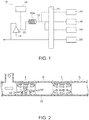
- FIG. 1 One example of a separation apparatus preferably for use in the separation method of the present invention is shown in Figure 1 .
- the separation apparatus 10 of the present invention shown in Figure 1 comprises a flow path 12, solution injection means 14, reagent injection means 16, bubble injection means 18, a liquid feed pump 20, a gas-liquid separator 22, and recovery means 26.
- the solution injection means 14 and the reagent injection means 16 are provided on the upstream side from the bubble injection means 18 in the flow path 12. Either one of the solution injection means 14 and the reagent injection means 16 may be on the more upstream side in the flow path 12.
- the bubble injection means 18 is further connected to the flow path 12 that has passed through the reagent injection means 16 and the solution injection means 14, and the flow path 12 that has passed through the bubble injection means 18 is guided to a coil portion 12a.
- the gas-liquid separator 22 is connected to the downstream side end of the flow path 12.
- a gas feed apparatus 24 may be provided on the upstream side of the vicinity of the gas-liquid separator 22 in the flow path 12, as desired.
- the recovery means 26 is connected to the gas outlet of the gas-liquid separator 22.
- a solution comprising a target component, and a reaction reagent capable of gasifying the target component are provided.
- the target component may be any component that can change into a gas state through the reaction with the reaction reagent, or the like.
- Preferred examples of the target component include Si, F, As, Sb, Se, Ge, Cl, and compounds thereof. More preferably, the target component is Si or a compound thereof and/or F or a compound thereof, further preferably Si or a compound thereof.
- the substance of interest from which the target component is separated is a liquid, it may be used as it is, or it may be diluted with any liquid.
- the solution comprising the target component can be formed by dissolving it by a known method using a liquid such as an acid, an alkali, or water.
- a liquid such as an acid, an alkali, or water.
- the solution comprising the target component can be preferably prepared by adding an appropriate amount of an acid such as hydrofluoric acid (1 + 1) to the metal or metal oxide and performing pressure decomposition.
- an acid such as hydrofluoric acid (1 + 1)
- reagent R (m + n) means a reagent in which a reagent R and water are mixed in a volume ratio of m:n (m and n are natural numbers).
- reaction reagents Two or more reaction reagents may be used, and in that case, all types of reaction reagents may be separately provided, or a mixture of some or all types of reaction reagents may be provided.
- the reaction does not proceed (that is, the target component does not gasify) by only adding some or all types of reaction reagents to the solution, previously adding some or all types of reaction reagents to the solution is allowed.
- the target component-containing solution and the reaction reagent provided in the above (1) are continuously fed to the flow path 12 from the solution injection means 14 and the reagent injection means 16 respectively. While the above liquid feed is performed, bubbles are intermittently injected from the bubble injection means 18 into the flow path 12. Thus, a gas-liquid slug flow in which the mixed liquid comprising the solution and the reaction reagent is segmented into a plurality of droplets by the bubbles is produced.
- the bubbles may comprise air, nitrogen gas, argon gas, or the like, and their type is not particularly limited.
- the solution injection means 14 also functions as the reagent injection means 16.
- the solution injection means 14 is not particularly limited as long as it is means or equipment that can continuously inject the solution into the flow path 12.
- a commercially available autosampler or the like can be preferably used.
- the reagent injection means 16 is not particularly limited as long as it is means or equipment that can continuously inject the reaction reagent into the flow path 12.
- means such as sucking the reaction reagent into the flow path 12 using a tube and a pump is also possible.
- the bubble injection means 18 is not particularly limited as long as it is means or equipment that can intermittently inject bubbles into the flow path 12 to produce the gas-liquid slug flow.
- means such as sucking bubbles into the flow path 12 using a tube and a pump is also possible.
- the timing of injecting bubbles can be preferably changed according to the viscosity and flow rates of the solution and the reaction reagent, and the like.
- a continuous flow analysis apparatus comprising such solution injection means 14, reagent injection means 16, and bubble injection means 18 is commercially available, and examples thereof include a group of products referred to as AutoAnalyzer manufactured by BL TEC K.K.
- the gas-liquid slug flow is composed of bubbles G occupying the cross section of the flow path 12, and droplets L segmented by these bubbles G being alternately present.
- the droplets L may comprise small bubbles of a size not occupying the cross section of the flow path 12.
- the mixing of neighboring droplets L with each other is prevented by the presence of the bubbles G, and therefore even when the target component is continuously separated from a different type of solution, the solution in another lot, or the like, the cross-contamination between the solutions can be kept to a minimum.
- the flow path 12 a commercially available tube or the like can be utilized as long as it is a member through which the target component-containing solution and the reaction reagent can be flowed.
- the flow path 12 is not particularly limited. From the viewpoint of easily producing the gas-liquid slug flow, the inner diameter of the flow path 12 is preferably 0.05 to 20 mm, more preferably 0.1 to 10 mm, and further preferably 0.1 to 2 mm.
- the flow path 12 is preferably composed of a resin.
- Preferred examples of the resin include fluororesins, PE (polyethylene), and PP (polypropylene). More preferably, the resin is a fluororesin from the viewpoint of acid resistance.
- fluororesins examples include PTFE (polytetrafluoroethylene), PFA (tetrafluoroethylene-perfluoroalkyl vinyl ether copolymer), and FEP (ethylene tetrafluoride-propylene hexafluoride copolymer).
- the flow path 12 is desirably composed of a material in which the target component is not contained, from the viewpoint of preventing contamination.
- the feed of the gas-liquid slug flow in the flow path 12 is continued by the liquid feed pump 20.
- the mixing of the solution and the reaction reagent, and the gasification of the target component by the mixing, in each droplet L, and the movement of the target component-derived gas produced by the gasification to the bubbles G are facilitated.
- the gas-liquid slug flow is fed to the downstream side (the right side in Figure 2 ) of the flow path 12, and thus convection occurs in the individual droplets L, and the mixing of the solution and the reaction reagent is promoted (mixing effect).
- a component A comprising the target component in the solution (which can be the target component itself) and a component B in the reaction reagent (which can be the reaction reagent itself) react with each other to produce a component AB.
- the produced component AB may be the target component-derived gas, or when the component AB changes further in the mixed liquid to form a component AB', as shown in Figure 2 , the component AB' may be the target component-derived gas.
- the mixing of the solution and the reaction reagent is promoted by the convection occurring in the droplets L, and thus the target component contained in the solution gasifies.
- the component AB or the component AB' that is the target component-derived gas produced by the gasification of the target component in this manner moves to the bubbles G, and thus the target component is vaporized and separated.
- the target component-derived gas can be efficiently extracted into the bubbles G by the fact that the mixing of the solution and the reaction reagent and the gasification of the target component are promoted by the above mixing effect, and that the droplets L and the bubbles G constitute the gas-liquid slug flow to increase the contact area between the liquid phase and the gas phase.
- the bubbles G achieve not only the effect of segmenting the droplets L to prevent cross-contamination, but also an effect as a medium into which the target component-derived gas is efficiently extracted by gas-liquid partition.
- reaction 1 H 2 SiO 3 + 6HF ⁇ H 2 SiF 6 + 3H 2 O
- reaction 2 H 2 SiF 6 ⁇ SiF 4 + 2HF
- Non Patent Literature 1 discloses that in order to vaporize and separate SiF 4 , nitrogen gas is passed through a solution at 1.0 L per minute for 30 minutes.
- a target component gas comprising Si typically SiF 4
- the method of the present invention is a simple method in which liquid feed is continued while a solution and a reaction reagent are segmented by bubbles, but a target component in a solution can be efficiently separated, and thus the quantitative analysis of the target component can be performed quickly and with high accuracy.
- the target component is separated by continuing the feed of the same solution and reaction reagent, and therefore the number of times of replacement of a sample and a reagent can be decreased (no replacement can be performed in some cases), and as a result, the risk of suffering a chemical injury or the like due to the replacement of the sample or the reagent can be decreased.
- the target component is separated in a flow path, and therefore it is also possible to effectively prevent or suppress the contamination of the sample by the mixing of foreign materials from the environment.
- the solution preferably comprises hydrofluoric acid
- the reaction reagent preferably comprises sulfuric acid.
- the reaction reagent preferably comprises another acid such as nitric acid or fuming nitric acid, instead of sulfuric acid.
- the target component-derived gas is preferably in the form of a fluoride and/or a hydride, more preferably in the form of a fluoride.
- the gasification of the target component is preferably performed at a temperature less than the boiling point of the solution from the viewpoint of performing quantitative analysis in which the influence of the acid or the like used is reduced.
- the heating here means applying heat to the flow path 12 from heating means outside the flow path 12, such as a heater, and does not include the heat accompanying the chemical reaction of the solution and the reaction reagent (that is, reaction heat).
- the separation apparatus 10 of the present invention preferably has no heating means.
- the separation apparatus 10 can have an even more simple and inexpensive configuration. However, heating may be performed when quantitative analysis can be performed with little influence from the acid or the like used.
- the liquid feed pump 20 is not particularly limited as long as it is a pump that facilitates the feed of the gas-liquid slug flow in the flow path 12, thereby being able to apply to the liquid a driving force that allows the mixing of the solution and the reaction reagent, and the gasification of the target component by the mixing, in each droplet, and the movement of the target component-derived gas produced by the gasification to the bubbles.
- Commercially available various pumps can be utilized.
- the liquid feed pump 20 is particularly preferably a tube pump such as a peristaltic pump.
- At least part of the flow path 12 preferably forms the coil portion 12a wound helically or in a figure eight shape, more preferably the helically wound coil portion 12a, from the viewpoint of being able to make the flow path space-saving.
- the step of continuing the feed of the gas-liquid slug flow is preferably performed through the coil portion 12a.
- the direction of the winding axis of the coil portion 12a is preferably the horizontal direction (that is, a state in which the coil portion 12a lies on its side).
- the coil portion 12a is preferably located on the downstream side of the bubble injection means 18 and on the upstream side of the gas-liquid separator 22 (the gas feed apparatus 24 when present).
- a commercially available coil tube can be used.
- the coil portion 12a is also preferably made of a fluororesin such as a PTFE resin or a PFA resin, as described above regarding the flow path 12.
- the coil total length of the coil portion 12a is preferably a length at which the target component in the solution is sufficiently separated, for example, 0.01 to 10 m, typically 0.5 to 2 m.
- the liquid feed rate of the gas-liquid slug flow is preferably 0.01 to 100 mL/minutes, more preferably 0.1 to 50 mL/minutes, and further preferably 1 to 10 mL/minutes.
- the target component-derived gas that has moved to the bubbles G is recovered with an absorbing liquid.
- This step is preferably performed by introducing the gas-liquid slug flow into the gas-liquid separator 22, while pushing the gas-liquid slug flow by a gas, to perform gas-liquid separation, and bringing the gas comprising the target component-derived gas (that is, the gas discharged from the gas outlet of the gas-liquid separator 22) separated from the gas-liquid slug flow into contact with the absorbing liquid by the recovery means 26.
- the gas-liquid separator 22 is not particularly limited as long as it can separate the bubbles comprising the target component-derived gas from the gas-liquid slug flow. A commercially available gas-liquid separator can be used.
- the recovery means 26 is not particularly limited as long as it can allow the absorbing liquid to absorb the target component-derived gas for recovery.
- the recovery means 26 can be means such as sucking and feeding the absorbing liquid using a tube, a liquid feed pump, and the like.
- a liquid that can sufficiently dissolve the target component-derived gas should be selected.
- the absorbing liquid is a liquid that selectively dissolves the target component-derived gas.
- a solution comprising boric acid, aluminum, zirconium, and/or a rare earth element that can dissolve SiF 4 , or the like can be the absorbing liquid.
- the type of the gas for pushing the gas-liquid slug flow into the gas-liquid separator 22 is not particularly limited, and the gas may be, for example, air, nitrogen gas, argon gas, or the like.
- the gas feed apparatus 24 for applying a gas to the gas-liquid slug flow to feed the gas-liquid slug flow in a gas-liquid separable state to the gas-liquid separator 22 is preferably provided in the vicinity of the gas-liquid separator 22 (for example, on the downstream side of the bubble injection means 18 and on the upstream side of the gas-liquid separator 22) in the flow path 12.
- the gas feed apparatus 24 include an air pump that feeds a gas at a pressure around atmospheric pressure, and a compressor that feeds a compressed gas.
- a further gas-liquid separator may be separately provided on the downstream side of the gas-liquid separator 22 in order to separate the recovery liquid comprising the target component-derived gas (that is, the absorbing liquid in which the target component-derived gas is recovered) from the gas not comprising the target component-derived gas (that is, the gas after being discharged from the gas outlet of the gas-liquid separator 22 and brought into contact with the absorbing liquid).
- the target component separated from the solution by the steps of the above (1) to (4) is quantitatively analyzed as desired.
- a method for analyzing a target component in a solution comprising the steps of separating a target component from a solution by the above method; and quantitatively analyzing the target component separated from the solution is provided.
- the target component is separated from interfering components that can be contained in the solution by the above-described separation method, and therefore high accuracy quantitative analysis in which the influence of the interfering components is eliminated can be performed.
- the step of quantitatively analyzing the target component is preferably performed by analysis equipment. Therefore, according to a preferred aspect of the present invention, an analysis apparatus comprising the separation apparatus 10 of the present invention; and analysis equipment (not shown) connected to the recovery means 26 of the separation apparatus 10 for quantitatively analyzing a target component is provided.
- the analysis equipment should be appropriately selected according to the type and concentration of the target component, and the like, and its type is not particularly limited. An absorptiometer is preferred in that simple analysis is possible and that it is relatively inexpensive.
- the recovery liquid (that is, the absorbing liquid comprising the target component) may be subjected to pretreatment such as a concentration operation and a coloring operation.
- pretreatment such as a concentration operation and a coloring operation.
- the type of the pretreatment is not particularly limited, and the pretreatment should be appropriately selected according to the type and concentration of the target component, the type of the analysis equipment, or the like.
- a coloring operation by a known method such as the molybdenum blue method described in Non Patent Literature 1 and the like is preferably performed.
- One example of a coloring operation by the molybdenum blue method includes adding a coloring reagent such as an ammonium molybdate solution to a recovery liquid under acidic conditions (for example, around pH 0.9), and adding a reducing reagent such as an ascorbic acid solution after the stop of the reaction.
- the analysis apparatus of the present invention may comprise means for performing pretreatment such as the above coloring operation (pretreatment means) on the downstream side of the separation apparatus 10 and on the upstream side of the analysis equipment.
- pretreatment means means for performing pretreatment such as the above coloring operation
- the separation of a target component in a solution to quantitative analysis including the pretreatment required at the time of quantitative analysis, can be collectively automatically performed.
- the method and apparatus of the present invention can be preferably applied to an automatic analysis apparatus.
- This analysis apparatus is represented by the system flow diagram shown in Figure 3 , and configurations other than the configurations of the flow paths (other than coil portions), coil portions, and gas-liquid separator shown below basically correspond to those of a continuous flow analysis apparatus (AutoAnalyzer, model number: AutoAnalyzer model 3 (AA3-R)) manufactured by BL TEC K.K.
- a continuous flow analysis apparatus AutoAnalyzer, model number: AutoAnalyzer model 3 (AA3-R)
- BL TEC K.K AutoAnalyzer model 3
- An analysis apparatus 110 shown in Figure 3 comprises a tube made of a fluororesin as a flow path 112.
- the flow path 112 branches on the upstream side, and the branched flow paths 112 are connected, via a peristaltic pump (tube pump), which is a liquid feed pump 120, to an autosampler, a first reagent bottle containing sulfuric acid (5 + 1), and a first bubble injection apparatus respectively to form solution injection means 114, first reagent injection means 116, and first bubble injection means 118.
- the first bubble injection means 118 is provided on the downstream side of the solution injection means 114 and the first reagent injection means 116.
- the flow path 112 has a helically wound first coil portion 112a on the downstream side of this first bubble injection means 118.
- a first gas-liquid separator 122 is connected to the downstream side end of the flow path 112, and a compressor, which is a gas feed apparatus 124, is provided in the vicinity of the upstream side of this first gas-liquid separator 122.
- a recovery means 126 is connected to the gas outlet of the first gas-liquid separator 122. From an absorbing liquid bottle containing boric acid (concentration 4 w/v%) at pH 0.9, which is an absorbing liquid, this recovery means 126 feeds the absorbing liquid to the gas outlet of the first gas-liquid separator 122 via the peristaltic pump.
- a second gas-liquid separator 128 is connected to the downstream side of the recovery means 126, and the liquid outlet side is connected to an analysis portion.
- a second bubble injection apparatus and a second reagent bottle containing ammonium molybdate (concentration 10 w/v%) are connected, in this order toward the downstream side, to the flow path 112 via the peristaltic pump to form second bubble injection means 130 and second reagent injection means 132 respectively.
- the flow path 112 has a second coil portion 112b on the downstream side from the connection position of the second reagent injection means 132.
- a third reagent bottle containing hydrochloric acid (3 N) and a fourth reagent bottle containing ascorbic acid (concentration 1 w/v%) are connected in this order to the flow path 112 via the peristaltic pump on the downstream side of the second coil portion 112b to form third reagent injection means 134 and fourth reagent injection means 136 respectively.
- the flow path 112 has a third coil portion 112c on the downstream side from the connection position of the fourth reagent injection means 136 and is connected to an absorptiometer, which is analysis equipment 138, on the downstream side of this third coil portion 112c.
- the absorptiometer comprises a flow cell having a width of 1.5 mm and an optical path length of 50 mm.
- the first coil portion 112a, the second coil portion 112b, and the third coil portion 112c were disposed so that the direction of the winding axis was the horizontal direction.
- This analysis apparatus is formed in order to analyze Si in a solution, but it is needless to say that target components other than Si can be analyzed by appropriately changing the types of the reagents, and the like.
- Standard solutions comprising Si at predetermined concentrations were made, Si was separated and analyzed according to the method of the present invention using the above apparatus, and a calibration curve was prepared to check linearity.
- a conventional apparatus and method, and the apparatus and method of the present invention were compared using a standard solution at a predetermined concentration. Specifically, the operations are as follows.
- Si in standard solutions was separated and analyzed according to the apparatus and method of the present invention, and a calibration curve was prepared, and repeatability was checked.
- Si in each standard solution was separated and analyzed using the provided analysis apparatus 110.
- Bubbles were intermittently injected from the first bubble injection means 118 into the flow path 112 at intervals of once every 2 seconds to turn the mixed liquid comprising the calibration curve solution and the sulfuric acid (5 + 1) into a gas-liquid slug flow in which the mixed liquid was segmented into a plurality of droplets by the bubbles, and this gas-liquid slug flow was fed to the downstream side of the flow path 112 by the liquid feed pump 120 at a flow rate of about 0.1 mL/minutes.
- the gas-liquid slug flow that arrived just in front of the first gas-liquid separator 122 through the first coil portion 112a was pushed into the first gas-liquid separator 122 by air fed from the gas feed apparatus 124 at a pressure of 0.06 MPa to separate the gas-liquid slug flow into a gas portion and a liquid portion.
- the gas portion separated from the gas-liquid slug flow was brought into contact with boric acid (concentration 4 w/v%) at pH 0.9, which was an absorbing liquid, fed from the recovery means 126, and the absorbing liquid and the mixed gas were fed to the second gas-liquid separator 128, and the recovery liquid discharged from the liquid outlet was fed to the analysis portion.
- the time from the feed of the standard solution to the flow path 112 to the arrival of the recovery liquid at the liquid outlet of the second gas-liquid separator 128 was about 2 minutes. Then, bubbles were intermittently injected at intervals of once every 4 seconds from the second bubble injection means 130 into the flow path 112 in the analysis portion where the recovery liquid was fed, and further an ammonium molybdate solution (concentration 10 w/v%), which was a coloring reagent, was injected from the second reagent injection means 132 to turn the mixed liquid comprising the recovery liquid and the coloring reagent into a gas-liquid slug flow in which the mixed liquid was segmented into a plurality of droplets by the bubbles.
- an ammonium molybdate solution concentration 10 w/v%
- a standard solution having a Si concentration of 0.25 mg/L was prepared as in the above (1) except that from the Si 1000 mg/L solution, an amount of the solution corresponding to 0.25 mg was fractionated.
- Si was separated and analyzed as in the above (2), and from the obtained absorbance, and the Si calibration curve prepared in the above (3), the Si concentration of the 0.25 mg/L standard solution was calculated.
- the above operation was performed 10 times, and the standard deviation ( ⁇ ) and 10 times the standard deviation (10 ⁇ ) were obtained. The results were as shown in Table 1.
- Si in standard solutions was separated and analyzed according to a conventional apparatus and method, and a calibration curve was prepared, and repeatability was checked.
- Si in each standard solution was separated and analyzed according to "10. Silicon Quantification Method" in JIS H 1403-2001 "Methods for chemical analysis of tungsten materials”.
- the separation instrument for Si was the same as in Figure 1 "Example of Silicon Tetrafluoride Vaporization Apparatus" in JIS H 1403-2001 except that the volume of the vaporization container and the absorption container was changed to 100 mL.
- For the absorbing liquid 50 mL of a boric acid solution (concentration 4 w/v%) was used, and the absorption time was 30 minutes.
- the coloration operation was performed as follows.
- the absorbing liquid was transferred to a volumetric flask (made of polypropylene, volume 100 mL), and 1 mL of hydrochloric acid (manufactured by KANTO CHEMICAL CO., INC., product number: 62900-03, trade name: "Hydrochloric acid EL 1 kg”) and 5 mL of an ammonium molybdate solution (concentration 10 w/v%) were added, and then the volumetric flask was shaken and allowed to stand for 15 minutes.
- hydrochloric acid manufactured by KANTO CHEMICAL CO., INC., product number: 62900-03, trade name: "Hydrochloric acid EL 1 kg
- an ammonium molybdate solution concentration 10 w/v%
- Example A1 and the Comparative Example (Example A2) are compared, substantially the same standard deviation as in the Comparative Example is obtained though in the Example, the sample concentration is low, about one twenty-fifth compared with the Comparative Example, and therefore it can be said that even when the sample concentration is low, analysis accuracy can be maintained. It can be said that this is due to the fact that the analysis was performed without the influence of contamination from the environment, or the like, and it can be said that high accuracy analysis is possible even in low concentration analysis. Further, as characteristics of the apparatus of the present invention, it is easy to increase the step in the separation portion to a plurality of steps and allow the absorbing liquid in the same recovery portion to absorb, and therefore analysis can be performed with higher sensitivity. In addition to this, by measuring a solution extracted using a solvent, the measurement sensitivity improves further.
- Standard solutions having Si concentrations of 0 mg/L (blank), 0.5 mg/L, 1.0 mg/L, 2.0 mg/L, and 5.0 mg/L were prepared as in (1) in Example A1 except that from the Si 1000 mg/L solution, amounts of the solutions corresponding to 0.5 mg, 1.0 mg, 2.0 mg, and 5.0 mg in terms of Si weight were fractionated.
- Si was separated and analyzed as in (2) in Example A1. From the Si concentration in each standard solution, and the absorbance of each standard solution obtained, a calibration curve of Si was prepared.
- the prepared Si calibration curve was as in Figure 5 . As shown in Figure 5 , the Si calibration curve shows good linearity, and its correlation coefficient r was 0.999 or more.
- Si in solutions was separated and analyzed as in (3) in Example B1 except that for the real sample, from a Si 100 mg/L solution made by diluting a Si 1000 mg/L solution, 0.1 mL of the solution was fractionated, and 4.0 mL of hydrofluoric acid (1 + 1) was added, and then pressure decomposition was performed to prepare each Si-added sample solution in which Si corresponding to 2.5 mg/L was added. From the obtained absorbance, and the Si calibration curve prepared in (2) in Example B1, the Si concentrations in the Si-added sample solutions were calculated, and the average value of the Si concentrations was obtained.
- the Si recovery rate when Si is added to the real sample is a value close to 100%, 98.94%, and therefore it can be said that it was confirmed that Si was reliably vaporized and separated and that accurate analysis was performed without the influence of the interfering components contained in the real sample and the like.
- a target component can be separated quickly but efficiently, and thus high accuracy quantitative analysis of a target component in which the influence of interfering components contained in a real sample and the like. is eliminated is possible.
Landscapes
- Life Sciences & Earth Sciences (AREA)
- Health & Medical Sciences (AREA)
- Physics & Mathematics (AREA)
- General Physics & Mathematics (AREA)
- Chemical & Material Sciences (AREA)
- Analytical Chemistry (AREA)
- Biochemistry (AREA)
- General Health & Medical Sciences (AREA)
- Immunology (AREA)
- Pathology (AREA)
- Molecular Biology (AREA)
- Spectroscopy & Molecular Physics (AREA)
- Engineering & Computer Science (AREA)
- Biomedical Technology (AREA)
- Investigating Or Analyzing Non-Biological Materials By The Use Of Chemical Means (AREA)
- Investigating Or Analysing Materials By Optical Means (AREA)
Abstract
Description
- The present invention relates to a method and apparatus for separating or analyzing a target component in a solution.
- In quantitative analysis to determine the content of a target component contained in a solution, interfering components that hinder the quantification of the target component may be mixed in the solution. In such a case, an operation to separate the target component from the interfering components is generally performed.
- In this respect, a method in which a target component in a solution is gasified for vaporization and separation is known. For example, Non Patent Literature 1 (JIS H 1403-2001 "Methods for chemical analysis of tungsten materials") discloses that regarding the separation of Si, a sample is decomposed by hydrogen peroxide, sulfuric acid is added to form an acidic solution, hydrofluoric acid is further added to this acidic solution, and then nitrogen gas is passed through the solution to vaporize and separate Si in the form of SiF4. Patent Literature 1 (
JP2017-146123A Non Patent Literature 1 described above, Si can be separated even in a sample insoluble in sulfuric acid or the like to which it is difficult to apply the method ofNon Patent Literature 1. - A method in which a gas sample comprising a target component is brought into continuous contact with an absorbing liquid that has high dissolving power for the target component or reacts selectively with the target component, to recover the target component is also known. For example, Patent Literature 2 (
JP2004-233061A - A method in which a sample is continuously injected into a tube together with a reagent while segmented by a gas, they are mixed, and this mixed liquid is decomposed in a reaction manifold and then analyzed by a detector, referred to as a continuous flow analysis method, is known. For example, Patent Literature 3 (
JP2009-288228A -
- Patent Literature 1:
JP2017-146123A - Patent Literature 2:
JP2004-233061A - Patent Literature 3:
JP2009-288228A - Non Patent Literature 1: JIS
H 1403-2001 - According to the vaporization and separation method by the gasification of a target component in a solution described above, the target component can be analyzed without the influence of interfering components, and therefore the vaporization and separation method is suitable for high accuracy and high sensitivity quantitative analysis. However, in the conventional method described in
Non Patent Literature 1 and the like, the time required for vaporization and separation is long, such as it being necessary to pass a gas (for example, for about 30 minutes) in order to separate a target component from a solution, and quick separation and analysis of the target component are hindered. Further problems are that there is a risk of suffering a chemical injury at the time of the replacement of a sample or a reagent, and that in low concentration analysis, contamination from the environment can occur. Therefore, a method for quickly performing analysis under conditions in which the influence of interfering components is eliminated and which are safe and without contamination from the environment is desired. - The present inventors have now obtained findings that by continuing liquid feed to a flow path while segmenting a solution and a reaction reagent by bubbles, a target component in a solution can be separated simply but safely and efficiently (for example, for about 2 minutes) without contamination from the environment because of being in the flow path, and thus the quantitative analysis of the target component can be performed quickly and with high accuracy.
- Therefore, it is an object of the present invention to provide a separation method in which a target component in a solution can be separated simply but safely and efficiently without contamination from the environment, and a quick and high accuracy method for analyzing a target component using such a separation method. It is another object of the present invention to provide a separation apparatus and an analysis apparatus that can implement such a separation method or analysis method.
- According to an aspect of the present invention there is provided a method for separating a target component in a solution, comprising the steps of:
- providing a solution comprising a target component, and a reaction reagent capable of gasifying the target component;
- while continuously feeding the solution and the reaction reagent to a flow path, intermittently injecting bubbles into the flow path to produce a gas-liquid slug flow in which a mixed liquid comprising the solution and the reaction reagent is segmented into a plurality of droplets by the bubbles;
- continuing the feed of the gas-liquid slug flow in the flow path, thereby facilitating the mixing of the solution and the reaction reagent, and the gasification of the target component by the mixing, in each droplet, and the movement of a target component-derived gas produced by the gasification to the bubbles; and
- recovering the target component-derived gas that has moved to the bubbles with an absorbing liquid.
- According to another aspect of the present invention, there is provided a method for analyzing a target component in a solution, comprising the steps of:
- separating the target component from the solution according to the above method; and
- quantitatively analyzing the target component separated from the solution.
- According to another aspect of the present invention, there is provided a separation apparatus for separating a target component in a solution, comprising:
- a flow path for flowing a solution comprising a target component, and a reaction reagent capable of gasifying the target component;
- solution injection means provided on an upstream side of the flow path for continuously injecting the solution into the flow path;
- reagent injection means provided on the upstream side of the flow path for continuously injecting the reaction reagent into the flow path;
- bubble injection means connected to the upstream side of the flow path and a downstream side of the solution injection means and the reagent injection means for intermittently injecting bubbles into the flow path to produce a gas-liquid slug flow in which a mixed liquid comprising the solution and the reaction reagent is segmented into a plurality of droplets by the bubbles;
- a liquid feed pump that facilitates the feed of the gas-liquid slug flow in the flow path, thereby allowing the mixing of the solution and the reaction reagent, and the gasification of the target component by the mixing, in each droplet, and the movement of a target component-derived gas produced by the gasification to the bubbles;
- a gas-liquid separator connected to a downstream side end of the flow path for separating the bubbles comprising the target component-derived gas from the gas-liquid slug flow; and
- recovery means connected to a gas outlet of the gas-liquid separator for allowing an absorbing liquid to absorb the target component-derived gas for recovery.
- According to another aspect of the present invention, there is provided an analysis apparatus for analyzing a target component in a solution, comprising:
- the separation apparatus; and
- analysis equipment connected to the recovery means of the separation apparatus for quantitatively analyzing the target component.
-
-
Figure 1 is a system flow diagram showing one example of the separation apparatus of the present invention. -
Figure 2 is a schematic diagram for conceptually explaining a gas-liquid slug flow in a flow path. -
Figure 3 is a system flow diagram of an analysis apparatus provided in Examples. -
Figure 4 is a Si calibration curve prepared in Example A1. -
Figure 5 is a Si calibration curve prepared in Example B1. - The method of the present invention comprises the steps of (1) the provision of a solution and a reaction reagent, (2) the production of a gas-liquid slug flow, (3) the gasification of a target component, (4) the recovery of a target component-derived gas, and (5) the quantitative analysis of the target component performed as desired.
- One example of a separation apparatus preferably for use in the separation method of the present invention is shown in
Figure 1 . Theseparation apparatus 10 of the present invention shown inFigure 1 comprises aflow path 12, solution injection means 14, reagent injection means 16, bubble injection means 18, aliquid feed pump 20, a gas-liquid separator 22, and recovery means 26. The solution injection means 14 and the reagent injection means 16 are provided on the upstream side from the bubble injection means 18 in theflow path 12. Either one of the solution injection means 14 and the reagent injection means 16 may be on the more upstream side in theflow path 12. More preferably, they are connected to theflow path 12 in the order of the reagent injection means 16 and the solution injection means 14 from the upstream side of theflow path 12, as shown inFigure 1 , in order to reduce the influence of the sulfuric acid and the like contained in the solution on viscosity and the like. The bubble injection means 18 is further connected to theflow path 12 that has passed through the reagent injection means 16 and the solution injection means 14, and theflow path 12 that has passed through the bubble injection means 18 is guided to acoil portion 12a. On the downstream side from thecoil portion 12a, the gas-liquid separator 22 is connected to the downstream side end of theflow path 12. Agas feed apparatus 24 may be provided on the upstream side of the vicinity of the gas-liquid separator 22 in theflow path 12, as desired. The recovery means 26 is connected to the gas outlet of the gas-liquid separator 22. Each of the steps (1) to (5) will be described below with appropriate reference to the drawings. - A solution comprising a target component, and a reaction reagent capable of gasifying the target component are provided. The target component may be any component that can change into a gas state through the reaction with the reaction reagent, or the like. Preferred examples of the target component include Si, F, As, Sb, Se, Ge, Cl, and compounds thereof. More preferably, the target component is Si or a compound thereof and/or F or a compound thereof, further preferably Si or a compound thereof. When the substance of interest from which the target component is separated is a liquid, it may be used as it is, or it may be diluted with any liquid. On the other hand, when the above substance of interest is a solid, the solution comprising the target component can be formed by dissolving it by a known method using a liquid such as an acid, an alkali, or water. For example, when the above substance of interest is a metal or a metal oxide, the solution comprising the target component can be preferably prepared by adding an appropriate amount of an acid such as hydrofluoric acid (1 + 1) to the metal or metal oxide and performing pressure decomposition. As used herein, "reagent R (m + n)" means a reagent in which a reagent R and water are mixed in a volume ratio of m:n (m and n are natural numbers).
- Two or more reaction reagents may be used, and in that case, all types of reaction reagents may be separately provided, or a mixture of some or all types of reaction reagents may be provided. When the reaction does not proceed (that is, the target component does not gasify) by only adding some or all types of reaction reagents to the solution, previously adding some or all types of reaction reagents to the solution is allowed.
- The target component-containing solution and the reaction reagent provided in the above (1) are continuously fed to the
flow path 12 from the solution injection means 14 and the reagent injection means 16 respectively. While the above liquid feed is performed, bubbles are intermittently injected from the bubble injection means 18 into theflow path 12. Thus, a gas-liquid slug flow in which the mixed liquid comprising the solution and the reaction reagent is segmented into a plurality of droplets by the bubbles is produced. The bubbles may comprise air, nitrogen gas, argon gas, or the like, and their type is not particularly limited. When all types of reaction reagents are previously added to the solution, the solution and the reaction reagent should be continuously fed from the solution injection means 14 to theflow path 12 without separately providing the reagent injection means 16. In this case, it can be said that the solution injection means 14 also functions as the reagent injection means 16. - The solution injection means 14 is not particularly limited as long as it is means or equipment that can continuously inject the solution into the
flow path 12. A commercially available autosampler or the like can be preferably used. The reagent injection means 16 is not particularly limited as long as it is means or equipment that can continuously inject the reaction reagent into theflow path 12. For example, means such as sucking the reaction reagent into theflow path 12 using a tube and a pump is also possible. The bubble injection means 18 is not particularly limited as long as it is means or equipment that can intermittently inject bubbles into theflow path 12 to produce the gas-liquid slug flow. For example, means such as sucking bubbles into theflow path 12 using a tube and a pump is also possible. For the bubble injection means 18, the timing of injecting bubbles can be preferably changed according to the viscosity and flow rates of the solution and the reaction reagent, and the like. A continuous flow analysis apparatus comprising such solution injection means 14, reagent injection means 16, and bubble injection means 18 is commercially available, and examples thereof include a group of products referred to as AutoAnalyzer manufactured by BL TEC K.K. - As shown in
Figure 2 , the gas-liquid slug flow is composed of bubbles G occupying the cross section of theflow path 12, and droplets L segmented by these bubbles G being alternately present. The droplets L may comprise small bubbles of a size not occupying the cross section of theflow path 12. In any case, the mixing of neighboring droplets L with each other is prevented by the presence of the bubbles G, and therefore even when the target component is continuously separated from a different type of solution, the solution in another lot, or the like, the cross-contamination between the solutions can be kept to a minimum. - For the
flow path 12, a commercially available tube or the like can be utilized as long as it is a member through which the target component-containing solution and the reaction reagent can be flowed. Theflow path 12 is not particularly limited. From the viewpoint of easily producing the gas-liquid slug flow, the inner diameter of theflow path 12 is preferably 0.05 to 20 mm, more preferably 0.1 to 10 mm, and further preferably 0.1 to 2 mm. Theflow path 12 is preferably composed of a resin. Preferred examples of the resin include fluororesins, PE (polyethylene), and PP (polypropylene). More preferably, the resin is a fluororesin from the viewpoint of acid resistance. Examples of preferred fluororesins include PTFE (polytetrafluoroethylene), PFA (tetrafluoroethylene-perfluoroalkyl vinyl ether copolymer), and FEP (ethylene tetrafluoride-propylene hexafluoride copolymer). Theflow path 12 is desirably composed of a material in which the target component is not contained, from the viewpoint of preventing contamination. - The feed of the gas-liquid slug flow in the
flow path 12 is continued by theliquid feed pump 20. Thus, the mixing of the solution and the reaction reagent, and the gasification of the target component by the mixing, in each droplet L, and the movement of the target component-derived gas produced by the gasification to the bubbles G are facilitated. In other words, as shown inFigure 2 , the gas-liquid slug flow is fed to the downstream side (the right side inFigure 2 ) of theflow path 12, and thus convection occurs in the individual droplets L, and the mixing of the solution and the reaction reagent is promoted (mixing effect). As a result, a component A comprising the target component in the solution (which can be the target component itself) and a component B in the reaction reagent (which can be the reaction reagent itself) react with each other to produce a component AB. The produced component AB may be the target component-derived gas, or when the component AB changes further in the mixed liquid to form a component AB', as shown inFigure 2 , the component AB' may be the target component-derived gas. In any case, the mixing of the solution and the reaction reagent is promoted by the convection occurring in the droplets L, and thus the target component contained in the solution gasifies. The component AB or the component AB' that is the target component-derived gas produced by the gasification of the target component in this manner moves to the bubbles G, and thus the target component is vaporized and separated. In this respect, in the method of the present invention, the target component-derived gas can be efficiently extracted into the bubbles G by the fact that the mixing of the solution and the reaction reagent and the gasification of the target component are promoted by the above mixing effect, and that the droplets L and the bubbles G constitute the gas-liquid slug flow to increase the contact area between the liquid phase and the gas phase. In this manner, in the method of the present invention, the bubbles G achieve not only the effect of segmenting the droplets L to prevent cross-contamination, but also an effect as a medium into which the target component-derived gas is efficiently extracted by gas-liquid partition. - For example, in the case of a solution comprising Si or a compound thereof as a target component, the following
reaction 1 and reaction 2 occur by the mixing of Si in a hydrofluoric acid and sulfuric acid solution. The symbol "⇔" in the reaction formulas indicates a reversible reaction.
Reaction 1: H2SiO3 + 6HF ⇔ H2SiF6 + 3H2O
Reaction 2: H2SiF6 ⇔ SiF4 + 2HF
- In other words, the reversible reaction of the
above reaction 1 proceeds in the right direction by a sulfuric acid dehydration reaction. Further, as shown in the reaction 2, a SiF4 molecule is produced by a collision between a H2SO4 molecule and a H2SiF6 molecule, and further the SiF4 gasifies by a collision between H2SO4 and the SiF4 molecule. In this respect,Non Patent Literature 1 discloses that in order to vaporize and separate SiF4, nitrogen gas is passed through a solution at 1.0 L per minute for 30 minutes. In contrast to this, according to the findings of the present inventors, it has been found that when the method of the present invention is used, a target component gas comprising Si (typically SiF4) can be extracted into the bubbles G in several tens of seconds to several minutes (for example, about 2 minutes). In this manner, the method of the present invention is a simple method in which liquid feed is continued while a solution and a reaction reagent are segmented by bubbles, but a target component in a solution can be efficiently separated, and thus the quantitative analysis of the target component can be performed quickly and with high accuracy. In addition, the target component is separated by continuing the feed of the same solution and reaction reagent, and therefore the number of times of replacement of a sample and a reagent can be decreased (no replacement can be performed in some cases), and as a result, the risk of suffering a chemical injury or the like due to the replacement of the sample or the reagent can be decreased. Moreover, the target component is separated in a flow path, and therefore it is also possible to effectively prevent or suppress the contamination of the sample by the mixing of foreign materials from the environment. - From the above viewpoints, the solution preferably comprises hydrofluoric acid, and the reaction reagent preferably comprises sulfuric acid. When the solution is insoluble in sulfuric acid, or when the precipitation of a sulfate or the like is caused, the reaction reagent preferably comprises another acid such as nitric acid or fuming nitric acid, instead of sulfuric acid. From the viewpoint of easily vaporizing and separating the target component, the target component-derived gas is preferably in the form of a fluoride and/or a hydride, more preferably in the form of a fluoride.
- The gasification of the target component is preferably performed at a temperature less than the boiling point of the solution from the viewpoint of performing quantitative analysis in which the influence of the acid or the like used is reduced. Thus, the target component can be separated even more quickly without requiring heating. Therefore, it is more preferred that heating is not performed on the
flow path 12. The heating here means applying heat to theflow path 12 from heating means outside theflow path 12, such as a heater, and does not include the heat accompanying the chemical reaction of the solution and the reaction reagent (that is, reaction heat). In other words, theseparation apparatus 10 of the present invention preferably has no heating means. Thus, theseparation apparatus 10 can have an even more simple and inexpensive configuration. However, heating may be performed when quantitative analysis can be performed with little influence from the acid or the like used. - The
liquid feed pump 20 is not particularly limited as long as it is a pump that facilitates the feed of the gas-liquid slug flow in theflow path 12, thereby being able to apply to the liquid a driving force that allows the mixing of the solution and the reaction reagent, and the gasification of the target component by the mixing, in each droplet, and the movement of the target component-derived gas produced by the gasification to the bubbles. Commercially available various pumps can be utilized. Theliquid feed pump 20 is particularly preferably a tube pump such as a peristaltic pump. - At least part of the
flow path 12 preferably forms thecoil portion 12a wound helically or in a figure eight shape, more preferably the helicallywound coil portion 12a, from the viewpoint of being able to make the flow path space-saving. The step of continuing the feed of the gas-liquid slug flow is preferably performed through thecoil portion 12a. Particularly, the direction of the winding axis of thecoil portion 12a is preferably the horizontal direction (that is, a state in which thecoil portion 12a lies on its side). Thus, the same effect as inverting and mixing the droplets L is obtained, and therefore even when there is a difference in specific gravity between the solution and the reaction reagent, or the like, mixing is smoothly performed, and the target component in the solution can be even more efficiently separated. As shown inFigure 1 , thecoil portion 12a is preferably located on the downstream side of the bubble injection means 18 and on the upstream side of the gas-liquid separator 22 (thegas feed apparatus 24 when present). For thecoil portion 12a, a commercially available coil tube can be used. Thecoil portion 12a is also preferably made of a fluororesin such as a PTFE resin or a PFA resin, as described above regarding theflow path 12. The coil total length of thecoil portion 12a is preferably a length at which the target component in the solution is sufficiently separated, for example, 0.01 to 10 m, typically 0.5 to 2 m. - From the viewpoint of balancing the quick separation of the target component and the recovery rate of the target component, for example, the liquid feed rate of the gas-liquid slug flow is preferably 0.01 to 100 mL/minutes, more preferably 0.1 to 50 mL/minutes, and further preferably 1 to 10 mL/minutes.
- The target component-derived gas that has moved to the bubbles G is recovered with an absorbing liquid. This step is preferably performed by introducing the gas-liquid slug flow into the gas-
liquid separator 22, while pushing the gas-liquid slug flow by a gas, to perform gas-liquid separation, and bringing the gas comprising the target component-derived gas (that is, the gas discharged from the gas outlet of the gas-liquid separator 22) separated from the gas-liquid slug flow into contact with the absorbing liquid by the recovery means 26. The gas-liquid separator 22 is not particularly limited as long as it can separate the bubbles comprising the target component-derived gas from the gas-liquid slug flow. A commercially available gas-liquid separator can be used. The recovery means 26 is not particularly limited as long as it can allow the absorbing liquid to absorb the target component-derived gas for recovery. For example, the recovery means 26 can be means such as sucking and feeding the absorbing liquid using a tube, a liquid feed pump, and the like. As the absorbing liquid, a liquid that can sufficiently dissolve the target component-derived gas should be selected. Preferably, the absorbing liquid is a liquid that selectively dissolves the target component-derived gas. For example, when Si or a compound thereof is separated and recovered in the form of SiF4, a solution comprising boric acid, aluminum, zirconium, and/or a rare earth element that can dissolve SiF4, or the like can be the absorbing liquid. The type of the gas for pushing the gas-liquid slug flow into the gas-liquid separator 22 is not particularly limited, and the gas may be, for example, air, nitrogen gas, argon gas, or the like. - From the viewpoint of efficiently performing gas-liquid separation, the
gas feed apparatus 24 for applying a gas to the gas-liquid slug flow to feed the gas-liquid slug flow in a gas-liquid separable state to the gas-liquid separator 22 is preferably provided in the vicinity of the gas-liquid separator 22 (for example, on the downstream side of the bubble injection means 18 and on the upstream side of the gas-liquid separator 22) in theflow path 12. Examples of thegas feed apparatus 24 include an air pump that feeds a gas at a pressure around atmospheric pressure, and a compressor that feeds a compressed gas. A further gas-liquid separator may be separately provided on the downstream side of the gas-liquid separator 22 in order to separate the recovery liquid comprising the target component-derived gas (that is, the absorbing liquid in which the target component-derived gas is recovered) from the gas not comprising the target component-derived gas (that is, the gas after being discharged from the gas outlet of the gas-liquid separator 22 and brought into contact with the absorbing liquid). - The target component separated from the solution by the steps of the above (1) to (4) is quantitatively analyzed as desired. In other words, according to a preferred aspect of the present invention, a method for analyzing a target component in a solution, comprising the steps of separating a target component from a solution by the above method; and quantitatively analyzing the target component separated from the solution is provided. In the analysis method of the present invention, the target component is separated from interfering components that can be contained in the solution by the above-described separation method, and therefore high accuracy quantitative analysis in which the influence of the interfering components is eliminated can be performed.
- The step of quantitatively analyzing the target component is preferably performed by analysis equipment. Therefore, according to a preferred aspect of the present invention, an analysis apparatus comprising the
separation apparatus 10 of the present invention; and analysis equipment (not shown) connected to the recovery means 26 of theseparation apparatus 10 for quantitatively analyzing a target component is provided. The analysis equipment should be appropriately selected according to the type and concentration of the target component, and the like, and its type is not particularly limited. An absorptiometer is preferred in that simple analysis is possible and that it is relatively inexpensive. - Before the quantitative analysis of the target component is performed, the recovery liquid (that is, the absorbing liquid comprising the target component) may be subjected to pretreatment such as a concentration operation and a coloring operation. The type of the pretreatment is not particularly limited, and the pretreatment should be appropriately selected according to the type and concentration of the target component, the type of the analysis equipment, or the like. For example, when Si or a compound thereof is quantitatively analyzed by an absorptiometer, a coloring operation by a known method such as the molybdenum blue method described in
Non Patent Literature 1 and the like is preferably performed. One example of a coloring operation by the molybdenum blue method includes adding a coloring reagent such as an ammonium molybdate solution to a recovery liquid under acidic conditions (for example, around pH 0.9), and adding a reducing reagent such as an ascorbic acid solution after the stop of the reaction. In this respect, the analysis apparatus of the present invention may comprise means for performing pretreatment such as the above coloring operation (pretreatment means) on the downstream side of theseparation apparatus 10 and on the upstream side of the analysis equipment. Thus, the separation of a target component in a solution to quantitative analysis, including the pretreatment required at the time of quantitative analysis, can be collectively automatically performed. In this manner, the method and apparatus of the present invention can be preferably applied to an automatic analysis apparatus. - The present invention will be more specifically described by the following examples.
- First, the configuration and specifications of the analysis apparatus used in the following examples will be described below. This analysis apparatus is represented by the system flow diagram shown in
Figure 3 , and configurations other than the configurations of the flow paths (other than coil portions), coil portions, and gas-liquid separator shown below basically correspond to those of a continuous flow analysis apparatus (AutoAnalyzer, model number: AutoAnalyzer model 3 (AA3-R)) manufactured by BL TEC K.K. For the flow paths connecting the components, the three types of tubes shown below were appropriately used. - Flow path: tube made of fluororesin (manufactured by FRON INDUSTRY, product number: F-8007-009, inner diameter: 1.19 mm)
- Flow path: tube made of fluororesin (manufactured by FRON INDUSTRY, product number: F-8011-001, inner diameter: 1 mm)
- Flow path: tube made of fluororesin (manufactured by FRON INDUSTRY, product number: F-8007-007, inner diameter: 0.96 mm)
- First coil portion: coil tube made of fluororesin (manufactured by BL TEC K.K., product number: TRA-8011-02, tube total length: 1 m, tube inner diameter: 2 mm, tube outer diameter: 3 mm, wall thickness 0.5 mm, number of coil tubes: one)
- Second coil portion: coil tubes made of fluororesin (manufactured by BL TEC K.K., product number: TRA-8011-02, tube total length: 1 m, tube inner diameter: 2 mm, tube outer diameter: 3 mm, wall thickness 0.5 mm, number of coil tubes: five (coupled to each other))
- Third coil portion: coil tubes made of fluororesin (manufactured by BL TEC K.K., product number: TRA-8011-02, tube total length: 1 m, tube inner diameter: 2 mm, tube outer diameter: 3 mm, wall thickness 0.5 mm, number of coil tubes: two (coupled to each other))
- Gas-liquid separator: (manufactured by BL TEC K.K., product name: PFA rectifying column, product number: PFA-1000-01)
- An
analysis apparatus 110 shown inFigure 3 comprises a tube made of a fluororesin as aflow path 112. Theflow path 112 branches on the upstream side, and thebranched flow paths 112 are connected, via a peristaltic pump (tube pump), which is aliquid feed pump 120, to an autosampler, a first reagent bottle containing sulfuric acid (5 + 1), and a first bubble injection apparatus respectively to form solution injection means 114, first reagent injection means 116, and first bubble injection means 118. The first bubble injection means 118 is provided on the downstream side of the solution injection means 114 and the first reagent injection means 116. Theflow path 112 has a helically woundfirst coil portion 112a on the downstream side of this first bubble injection means 118. A first gas-liquid separator 122 is connected to the downstream side end of theflow path 112, and a compressor, which is agas feed apparatus 124, is provided in the vicinity of the upstream side of this first gas-liquid separator 122. A recovery means 126 is connected to the gas outlet of the first gas-liquid separator 122. From an absorbing liquid bottle containing boric acid (concentration 4 w/v%) at pH 0.9, which is an absorbing liquid, this recovery means 126 feeds the absorbing liquid to the gas outlet of the first gas-liquid separator 122 via the peristaltic pump. A second gas-liquid separator 128 is connected to the downstream side of the recovery means 126, and the liquid outlet side is connected to an analysis portion. In the analysis portion, a second bubble injection apparatus and a second reagent bottle containing ammonium molybdate (concentration 10 w/v%) are connected, in this order toward the downstream side, to theflow path 112 via the peristaltic pump to form second bubble injection means 130 and second reagent injection means 132 respectively. Theflow path 112 has asecond coil portion 112b on the downstream side from the connection position of the second reagent injection means 132. A third reagent bottle containing hydrochloric acid (3 N) and a fourth reagent bottle containing ascorbic acid (concentration 1 w/v%) are connected in this order to theflow path 112 via the peristaltic pump on the downstream side of thesecond coil portion 112b to form third reagent injection means 134 and fourth reagent injection means 136 respectively. Theflow path 112 has athird coil portion 112c on the downstream side from the connection position of the fourth reagent injection means 136 and is connected to an absorptiometer, which isanalysis equipment 138, on the downstream side of thisthird coil portion 112c. The absorptiometer comprises a flow cell having a width of 1.5 mm and an optical path length of 50 mm. Thefirst coil portion 112a, thesecond coil portion 112b, and thethird coil portion 112c were disposed so that the direction of the winding axis was the horizontal direction. This analysis apparatus is formed in order to analyze Si in a solution, but it is needless to say that target components other than Si can be analyzed by appropriately changing the types of the reagents, and the like. - Standard solutions comprising Si at predetermined concentrations were made, Si was separated and analyzed according to the method of the present invention using the above apparatus, and a calibration curve was prepared to check linearity. In addition, a conventional apparatus and method, and the apparatus and method of the present invention were compared using a standard solution at a predetermined concentration. Specifically, the operations are as follows.
- Si in standard solutions was separated and analyzed according to the apparatus and method of the present invention, and a calibration curve was prepared, and repeatability was checked.
- From a Si 1000 mg/L solution (manufactured by KANTO CHEMICAL CO., INC., product number: 37811-2B), amounts of the solutions corresponding to 0.02 mg, 0.05 mg, 0.1 mg, and 0.5 mg in terms of Si weight were fractionated and charged into separate volumetric flasks (made of polypropylene, volume 1000 mL). For blank solution preparation, an empty volumetric flask (made of polypropylene, volume 1000 mL) in which the Si 1000 mg/L solution was not fractionated was separately provided. 165 mL of hydrofluoric acid (manufactured by Morita Chemical Industries Co., Ltd., concentration 50% by volume) was added to each volumetric flask, and the contents were set at a constant volume with pure water. In this manner, standard solutions having Si concentrations of 0 mg/L (blank), 0.02 mg/L, 0.05 mg/L, 0.1 mg/L, and 0.5 mg/L were prepared.
- Si in each standard solution was separated and analyzed using the provided
analysis apparatus 110. First, about 2 mL of the obtained standard solution was continuously fed to theflow path 112 by the solution injection means 114, and sulfuric acid (5 + 1), which was a reaction reagent, was continuously fed from the first reagent injection means 116 to theflow path 112. Bubbles were intermittently injected from the first bubble injection means 118 into theflow path 112 at intervals of once every 2 seconds to turn the mixed liquid comprising the calibration curve solution and the sulfuric acid (5 + 1) into a gas-liquid slug flow in which the mixed liquid was segmented into a plurality of droplets by the bubbles, and this gas-liquid slug flow was fed to the downstream side of theflow path 112 by theliquid feed pump 120 at a flow rate of about 0.1 mL/minutes. The gas-liquid slug flow that arrived just in front of the first gas-liquid separator 122 through thefirst coil portion 112a was pushed into the first gas-liquid separator 122 by air fed from thegas feed apparatus 124 at a pressure of 0.06 MPa to separate the gas-liquid slug flow into a gas portion and a liquid portion. The gas portion separated from the gas-liquid slug flow was brought into contact with boric acid (concentration 4 w/v%) at pH 0.9, which was an absorbing liquid, fed from the recovery means 126, and the absorbing liquid and the mixed gas were fed to the second gas-liquid separator 128, and the recovery liquid discharged from the liquid outlet was fed to the analysis portion. The time from the feed of the standard solution to theflow path 112 to the arrival of the recovery liquid at the liquid outlet of the second gas-liquid separator 128 was about 2 minutes. Then, bubbles were intermittently injected at intervals of once every 4 seconds from the second bubble injection means 130 into theflow path 112 in the analysis portion where the recovery liquid was fed, and further an ammonium molybdate solution (concentration 10 w/v%), which was a coloring reagent, was injected from the second reagent injection means 132 to turn the mixed liquid comprising the recovery liquid and the coloring reagent into a gas-liquid slug flow in which the mixed liquid was segmented into a plurality of droplets by the bubbles. After this gas-liquid slug flow passed through thesecond coil portion 112b, hydrochloric acid (3 N), which was a reaction-stopping liquid, and ascorbic acid (concentration 1 w/v%), which was a reducing reagent, were injected into theflow path 112 from the third reagent injection means 134 and the fourth reagent injection means 136 respectively. Then, the liquid portion of the gas-liquid slug flow that passed through thethird coil portion 112c was introduced into the absorptiometer, which was theanalysis equipment 138, connected to theflow path 112 end, and the absorbance at a wavelength of 800 nm was measured. From the Si concentration in each standard solution, and the absorbance of each standard solution obtained, a calibration curve of Si was prepared. The prepared Si calibration curve was as inFigure 4 . As shown inFigure 4 , the Si calibration curve shows good linearity, and its correlation coefficient r was 0.999 or more. - A standard solution having a Si concentration of 0.25 mg/L was prepared as in the above (1) except that from the Si 1000 mg/L solution, an amount of the solution corresponding to 0.25 mg was fractionated. For the 0.25 mg/L standard solution, Si was separated and analyzed as in the above (2), and from the obtained absorbance, and the Si calibration curve prepared in the above (3), the Si concentration of the 0.25 mg/L standard solution was calculated. The above operation was performed 10 times, and the standard deviation (σ) and 10 times the standard deviation (10 σ) were obtained. The results were as shown in Table 1.
- Si in standard solutions was separated and analyzed according to a conventional apparatus and method, and a calibration curve was prepared, and repeatability was checked.
- The standard solutions having Si concentrations of 0 mg/L (blank), 0.02 mg/L, 0.05 mg/L, 0.1 mg/L, and 0.5 mg/L prepared in (1) in Example A1 were used as they were.
- Si in each standard solution was separated and analyzed according to "10. Silicon Quantification Method" in JIS H 1403-2001 "Methods for chemical analysis of tungsten materials". The separation instrument for Si was the same as in
Figure 1 "Example of Silicon Tetrafluoride Vaporization Apparatus" in JIS H 1403-2001 except that the volume of the vaporization container and the absorption container was changed to 100 mL. For the absorbing liquid, 50 mL of a boric acid solution (concentration 4 w/v%) was used, and the absorption time was 30 minutes. The coloration operation was performed as follows. First, the absorbing liquid was transferred to a volumetric flask (made of polypropylene, volume 100 mL), and 1 mL of hydrochloric acid (manufactured by KANTO CHEMICAL CO., INC., product number: 62900-03, trade name: "Hydrochloric acid EL 1 kg") and 5 mL of an ammonium molybdate solution (concentration 10 w/v%) were added, and then the volumetric flask was shaken and allowed to stand for 15 minutes. Then, 5 mL of hydrochloric acid and 1 mL of L-ascorbic acid (concentration 5 w/v%) were added to this volumetric flask, and the mixture was set at a constant volume of 100 mL with a boric acid solution. The volumetric flask was shaken and allowed to stand for 30 minutes, and then the absorbance at 800 nm was measured by an absorptiometer, and from the obtained absorbance, a Si calibration curve was prepared. - For the 0.25 mg/L standard solution prepared in (3) in Example A1, Si was separated and analyzed as in the above (2). From the obtained absorbance, and the Si calibration curve prepared in the above (2), the Si concentration of the 0.25 mg/L standard solution was calculated. The above operation was performed 10 times, and the standard deviation (σ) and 10 times the standard deviation (10 σ) were obtained. The results were as shown in Table 1.
- [Table 1]
Table 1 Si concentration Ex. A1 Ex. A2* Analytical value of 0.25 mg/L standard solution (mg/L) Sample concentration (µg/g) Analytical value of 0.25 mg/L standard solution (mg/L) Sample concentration (µg/g) n 1 0.261 1.044 0.257 25.7 2 0.262 1.048 0.252 25.2 3 0.264 1.056 0.251 25.1 4 0.252 1.008 0.251 25.1 5 0.259 1.036 0.256 25.6 6 0.262 1.048 0.252 25.2 7 0.258 1.032 0.254 25.4 8 0.261 1.044 0.258 25.8 9 0.264 1.056 0.250 25.0 10 0.260 1.040 0.252 25.2 Standard deviation σ 0.00350 0.0133 0.00265 0.265 10σ 0.0350 0.133 0.0265 2.65 * indicates a Comparative Example. - When the Example (Example A1) and the Comparative Example (Example A2) are compared, substantially the same standard deviation as in the Comparative Example is obtained though in the Example, the sample concentration is low, about one twenty-fifth compared with the Comparative Example, and therefore it can be said that even when the sample concentration is low, analysis accuracy can be maintained. It can be said that this is due to the fact that the analysis was performed without the influence of contamination from the environment, or the like, and it can be said that high accuracy analysis is possible even in low concentration analysis. Further, as characteristics of the apparatus of the present invention, it is easy to increase the step in the separation portion to a plurality of steps and allow the absorbing liquid in the same recovery portion to absorb, and therefore analysis can be performed with higher sensitivity. In addition to this, by measuring a solution extracted using a solvent, the measurement sensitivity improves further.
- A Si addition and recovery test was performed, and the recovery rate was calculated. Specifically, the operations are as follows.
- Standard solutions having Si concentrations of 0 mg/L (blank), 0.5 mg/L, 1.0 mg/L, 2.0 mg/L, and 5.0 mg/L were prepared as in (1) in Example A1 except that from the Si 1000 mg/L solution, amounts of the solutions corresponding to 0.5 mg, 1.0 mg, 2.0 mg, and 5.0 mg in terms of Si weight were fractionated.
- For each standard solution prepared in the above (1), Si was separated and analyzed as in (2) in Example A1. From the Si concentration in each standard solution, and the absorbance of each standard solution obtained, a calibration curve of Si was prepared. The prepared Si calibration curve was as in
Figure 5 . As shown inFigure 5 , the Si calibration curve shows good linearity, and its correlation coefficient r was 0.999 or more. - 1.0 g of a Ta2O5 sample provided as a real sample was weighed and charged into a pressure decomposition container (manufactured by SAN-AI Kagaku Co. Ltd., product number: HUS-25), and further 4.0 mL of hydrofluoric acid (1 + 1) was added, and then the pressure decomposition container was heated at 150°C for 5 hours using a dryer (manufactured by Yamato Scientific Co., Ltd., product number: DS400). The hydrofluoric acid (1 + 1) was prepared by adding 1 volume of water to 1 volume of hydrofluoric acid (manufactured by Morita Chemical Industries Co., Ltd., concentration 50% by volume). In this manner, a sample solution in which the real sample was pressure-decomposed was obtained. The above operation was carried out twice to obtain two sample solutions. For these sample solutions, Si in the solutions was separated and analyzed as in (2) in Example A1. The obtained absorbance, and the Si concentrations in the sample solutions were calculated. The results were as shown in Table 2.
- Si in solutions was separated and analyzed as in (3) in Example B1 except that for the real sample, from a Si 100 mg/L solution made by diluting a Si 1000 mg/L solution, 0.1 mL of the solution was fractionated, and 4.0 mL of hydrofluoric acid (1 + 1) was added, and then pressure decomposition was performed to prepare each Si-added sample solution in which Si corresponding to 2.5 mg/L was added. From the obtained absorbance, and the Si calibration curve prepared in (2) in Example B1, the Si concentrations in the Si-added sample solutions were calculated, and the average value of the Si concentrations was obtained. From the Si concentration average value of the Si-added sample solutions obtained, the Si concentration average value of the sample solutions obtained in Example B1 was subtracted, and the result was divided by the Si addition concentration (corresponding to 2.5 mg/L) to obtain the recovery rate of Si. The results were as shown in Table 2.
[Table 2]Table 2 Solution type Si concentration [mg/L] Si recovery rate [%] n Average 1 2 Ex. B1 Ta2O5+HF(1+1) 0.066 0.071 0.0685 - Ex. B2 Ta2O5+HF(1 +1)+Si2.5mg/L 2.499 2.585 2.542 98.94 - As shown in Table 2, the Si recovery rate when Si is added to the real sample is a value close to 100%, 98.94%, and therefore it can be said that it was confirmed that Si was reliably vaporized and separated and that accurate analysis was performed without the influence of the interfering components contained in the real sample and the like. In this manner, it is found that according to the method of the present invention, a target component can be separated quickly but efficiently, and thus high accuracy quantitative analysis of a target component in which the influence of interfering components contained in a real sample and the like. is eliminated is possible.
Claims (18)
- A method for separating a target component in a solution, comprising the steps of:providing a solution comprising a target component, and a reaction reagent capable of gasifying the target component;while continuously feeding the solution and the reaction reagent to a flow path, intermittently injecting bubbles into the flow path to produce a gas-liquid slug flow in which a mixed liquid comprising the solution and the reaction reagent is segmented into a plurality of droplets by the bubbles;continuing the feed of the gas-liquid slug flow in the flow path, thereby facilitating the mixing of the solution and the reaction reagent, and the gasification of the target component by the mixing, in each droplet, and the movement of a target component-derived gas produced by the gasification to the bubbles; andrecovering the target component-derived gas that has moved to the bubbles with an absorbing liquid.
- The method according to claim 1, wherein at least part of the flow path forms a coil portion wound helically or in a figure eight shape, and the step of continuing the feed of the gas-liquid slug flow is performed through the coil portion.
- The method according to claim 1 or 2, wherein the step of recovering the target component-derived gas with an absorbing liquid is performed by performing gas-liquid separation while pushing the gas-liquid slug flow by a gas, and bringing a gas separated from the gas-liquid slug flow into contact with the absorbing liquid.
- The method according to any one of claims 1 to 3, wherein the gasification of the target component is performed at a temperature less than a boiling point of the solution.
- The method according to any one of claims 1 to 4, wherein the target component is Si or a compound thereof and/or is F or a compound thereof.
- The method according to any one of claims 1 to 5, wherein the target component-derived gas is in a form of a fluoride.
- The method according to any one of claims 1 to 6, wherein the solution comprises hydrofluoric acid, and the reaction reagent comprises sulfuric acid.
- A method for analyzing a target component in a solution, comprising the steps of:separating the target component from the solution according to the method according to any one of claims 1 to 7; andquantitatively analyzing the target component separated from the solution.
- The method according to claim 8, wherein the step of quantitatively analyzing the target component is performed by an absorptiometer.
- A separation apparatus for separating a target component in a solution, comprising:a flow path for flowing a solution comprising a target component, and a reaction reagent capable of gasifying the target component;solution injection means provided on an upstream side of the flow path for continuously injecting the solution into the flow path;reagent injection means provided on the upstream side of the flow path for continuously injecting the reaction reagent into the flow path;bubble injection means connected to the upstream side of the flow path and a downstream side of the solution injection means and the reagent injection means for intermittently injecting bubbles into the flow path to produce a gas-liquid slug flow in which a mixed liquid comprising the solution and the reaction reagent is segmented into a plurality of droplets by the bubbles;a liquid feed pump that facilitates the feed of the gas-liquid slug flow in the flow path, thereby allowing the mixing of the solution and the reaction reagent, and the gasification of the target component by the mixing, in each droplet, and the movement of a target component-derived gas produced by the gasification to the bubbles;a gas-liquid separator connected to a downstream side end of the flow path for separating the bubbles comprising the target component-derived gas from the gas-liquid slug flow; andrecovery means connected to a gas outlet of the gas-liquid separator for allowing an absorbing liquid to absorb the target component-derived gas for recovery.
- The apparatus according to claim 10, further comprising a gas feed apparatus provided in the vicinity of the gas-liquid separator in the flow path for applying a gas to the gas-liquid slug flow to feed the gas-liquid slug flow in a gas-liquid separable state to the gas-liquid separator.
- The apparatus according to claim 10 or 11, wherein at least part of the flow path is wound helically or in a figure eight shape to form a coil portion.
- The apparatus according to any one of claims 10 to 12, wherein the flow path has an inner diameter of 0.05 to 20 mm.
- The apparatus according to any one of claims 10 to 13, wherein the target component is Si or a compound thereof and/or is F or a compound thereof.
- The apparatus according to any one of claims 10 to 14, wherein the flow path is composed of a resin.
- The apparatus according to any one of claims 10 to 15 for use in the method according to any one of claims 1 to 7.
- An analysis apparatus for analyzing a target component in a solution, comprising:the separation apparatus according to any one of claims 10 to 16; andanalysis equipment connected to the recovery means of the separation apparatus for quantitatively analyzing the target component.
- The apparatus according to claim 17, wherein the analysis equipment is an absorptiometer.
Applications Claiming Priority (2)
| Application Number | Priority Date | Filing Date | Title |
|---|---|---|---|
| JP2018226851A JP6617191B1 (en) | 2018-12-03 | 2018-12-03 | Method and apparatus for separating or analyzing target components in a solution |
| PCT/JP2019/046341 WO2020116274A1 (en) | 2018-12-03 | 2019-11-27 | Method and device for isolating and analyzing target substance in solution |
Publications (3)
| Publication Number | Publication Date |
|---|---|
| EP3839501A1 true EP3839501A1 (en) | 2021-06-23 |
| EP3839501A4 EP3839501A4 (en) | 2021-10-27 |
| EP3839501B1 EP3839501B1 (en) | 2023-09-06 |
Family
ID=68835995
Family Applications (1)
| Application Number | Title | Priority Date | Filing Date |
|---|---|---|---|
| EP19894137.9A Active EP3839501B1 (en) | 2018-12-03 | 2019-11-27 | Method and device for isolating and analyzing target substance in solution |
Country Status (6)
| Country | Link |
|---|---|
| US (1) | US11215592B2 (en) |
| EP (1) | EP3839501B1 (en) |
| JP (1) | JP6617191B1 (en) |
| KR (1) | KR102281553B1 (en) |
| CN (1) | CN112740031B (en) |
| WO (1) | WO2020116274A1 (en) |
Families Citing this family (3)
| Publication number | Priority date | Publication date | Assignee | Title |
|---|---|---|---|---|
| CN117999480A (en) * | 2021-09-30 | 2024-05-07 | 株式会社岛津制作所 | Gas-liquid separator, total organic carbon analyzer and analysis system |
| CN118103702B (en) * | 2022-03-30 | 2025-06-03 | 必艾路泰克株式会社 | Reduction component, analysis device and analysis method |
| KR102864724B1 (en) | 2022-12-08 | 2025-09-26 | 주식회사 한테크 | Vibration mixer and apparatus for separating different materials comprising the same |
Family Cites Families (20)
| Publication number | Priority date | Publication date | Assignee | Title |
|---|---|---|---|---|
| JPS6237161Y2 (en) * | 1980-04-10 | 1987-09-22 | ||
| JPS5930062A (en) * | 1982-08-13 | 1984-02-17 | Nippon Steel Corp | Continuous analysis |
| JPS60102542A (en) * | 1983-11-09 | 1985-06-06 | Hitachi Ltd | Analyzing apparatus for reducing and vaporizing element |
| JPS617467A (en) * | 1984-06-22 | 1986-01-14 | Mitsui Petrochem Ind Ltd | Flow injection analysis |
| US5668014A (en) | 1994-06-06 | 1997-09-16 | Kabushiki Kaisha Meidensha | Device and method for estimating three nitrogen-including ionic substances in water |
| JP3446583B2 (en) * | 1997-01-30 | 2003-09-16 | 三菱マテリアル株式会社 | Hydride generation analyzer |
| GB9801281D0 (en) | 1997-01-30 | 1998-03-18 | Mitsubishi Materials Corp | Hydride formation analytical apparatus |
| JP2004233061A (en) | 2003-01-28 | 2004-08-19 | National Cancer Center-Japan | Continuously enriched gas sampling device by nebulizer / denuder connection, gas analyzer incorporating the gas sampling device, and analysis method |
| KR20050059752A (en) * | 2003-12-15 | 2005-06-21 | 삼성전자주식회사 | Device and method for pumping fluids utilizing gas bubble in microscale |
| GB0521716D0 (en) * | 2005-10-25 | 2005-11-30 | Genomica Sau | Modulation of 11beta-hydroxysteriod dehydrogenase 1 expression for the treatment of ocular diseases |
| GB0806771D0 (en) * | 2008-04-12 | 2008-05-14 | Spd Swiss Prec Diagnostics Gmb | Assay devices comprising bubble-forming means |
| KR100875629B1 (en) * | 2008-05-29 | 2008-12-26 | 비엘텍 코리아 주식회사 | Automatic analysis quantitative measurement method and automatic analysis quantitative measurement device |
| JP2010044034A (en) * | 2008-08-12 | 2010-02-25 | Taiheiyo Consultant:Kk | Fluorine analysis method and fluorine analysis system |
| JP5489283B2 (en) * | 2010-05-24 | 2014-05-14 | 株式会社日立ハイテクノロジーズ | Automatic analyzer |
| JP2014016299A (en) * | 2012-07-11 | 2014-01-30 | Shimadzu Corp | Automatic analyzer and method for incorporating bubbles |
| JP5941794B2 (en) * | 2012-08-30 | 2016-06-29 | 新日鉄住金エンジニアリング株式会社 | Soil continuous analysis method |
| US10018040B2 (en) | 2014-10-24 | 2018-07-10 | Schlumberger Technology Corporation | System and methodology for chemical constituent sensing and analysis |
| EP3294109B1 (en) | 2015-05-12 | 2024-03-27 | Avraham Levy | Dynamic field of view endoscope |
| CN105181593B (en) * | 2015-10-14 | 2019-02-12 | 厦门大学 | A non-bubble interference flow cell, flow analysis-optical detection device and use |
| JP6416807B2 (en) * | 2016-02-15 | 2018-10-31 | 日鉄住金テクノロジー株式会社 | Silicon quantitative analysis method |
-
2018
- 2018-12-03 JP JP2018226851A patent/JP6617191B1/en active Active
-
2019
- 2019-11-27 US US17/278,446 patent/US11215592B2/en active Active
- 2019-11-27 CN CN201980061981.1A patent/CN112740031B/en active Active
- 2019-11-27 EP EP19894137.9A patent/EP3839501B1/en active Active
- 2019-11-27 WO PCT/JP2019/046341 patent/WO2020116274A1/en not_active Ceased
- 2019-11-27 KR KR1020217006629A patent/KR102281553B1/en active Active
Also Published As
| Publication number | Publication date |
|---|---|
| CN112740031B (en) | 2021-11-02 |
| WO2020116274A1 (en) | 2020-06-11 |
| US11215592B2 (en) | 2022-01-04 |
| EP3839501B1 (en) | 2023-09-06 |
| EP3839501A4 (en) | 2021-10-27 |
| CN112740031A (en) | 2021-04-30 |
| JP2020091128A (en) | 2020-06-11 |
| KR20210031757A (en) | 2021-03-22 |
| KR102281553B1 (en) | 2021-07-26 |
| JP6617191B1 (en) | 2019-12-11 |
| US20210318278A1 (en) | 2021-10-14 |
Similar Documents
| Publication | Publication Date | Title |
|---|---|---|
| EP3839501B1 (en) | Method and device for isolating and analyzing target substance in solution | |
| Vesna et al. | Product study of oleic acid ozonolysis as function of humidity | |
| Lee et al. | Simultaneous measurements of atmospheric HONO and NO2 via absorption spectroscopy using tunable mid-infrared continuous-wave quantum cascade lasers | |
| US12235250B2 (en) | Radiopharmaceutical production system and quality control system utilizing high performance liquid chromatography | |
| Elrod et al. | Direct kinetics study of the temperature dependence of the CH2O branching channel for the CH3O2+ HO2 reaction | |
| CN104007218B (en) | The assay method of bisphenol S migration amount in a kind of plastic food packaging materials | |
| CN106855545A (en) | Liposoluble vitamin simultaneously in detection feed and the method for water soluble vitamin | |
| Pang et al. | A smog chamber comparison of a microfluidic derivatisation measurement of gas-phase glyoxal and methylglyoxal with other analytical techniques | |
| Schimpf et al. | Determination of carotenoids in infant, pediatric, and adult nutritionals by HPLC with UV-visible detection: single-laboratory validation, first action 2017.04 | |
| CN105758945A (en) | Method for detecting bisphenol compound in canned tuna | |
| US20030228708A1 (en) | Process and apparatus for providing a gaseous substance for the analysis of chemical elements or compounds | |
| CN106770615A (en) | The method that Sulphur Dioxide in Chinese Herbal Medicines by Iodine Titration Method is remained is determined using ICP MS methods | |
| Gilliland et al. | Simultaneous determination of vitamins D2 and D3 by LC-MS/MS in infant formula and adult nutritionals: First Action 2011.13 | |
| US8114672B2 (en) | Method for analyzing antimony contained in glass | |
| EP1988392B1 (en) | Liquid chromatograph | |
| CN105974021A (en) | Method for detecting illegally added propoxyadenafil | |
| CN106770726A (en) | A kind of detection method of residual organic solvent in mecobalamin | |
| EP0873507B1 (en) | Device and method for supercritical fluid extraction (sfe) | |
| WO2022219113A1 (en) | Laboratory system for sampling reactor contents | |
| EP3652531B1 (en) | Device and method for continuous analysis of the concentration of dissolved inorganic carbon (dic) and of the isotopic carbon and oxygen compositions thereof | |
| CN113281447A (en) | Extraction device, determination method and system for saccharin sodium in paper surface layer and application | |
| Gilliland et al. | Simultaneous determination of vitamins D2 and D3 by electrospray ionization LC/MS/MS in infant formula and adult nutritionals: first action 2012.11 | |
| DE10256009B4 (en) | Method and apparatus for providing a gaseous substance for the analysis of chemical elements or compounds | |
| Supriyanto et al. | A NOVEL METHOD OF THE HYDRIDE SEPARATION FOR THE DETERMINATION OF ARSENIC AND ANTIMONY BY AAS | |
| KR20240158903A (en) | Collection system for recovery of separated radioactive fractions |
Legal Events
| Date | Code | Title | Description |
|---|---|---|---|
| STAA | Information on the status of an ep patent application or granted ep patent |
Free format text: STATUS: THE INTERNATIONAL PUBLICATION HAS BEEN MADE |
|
| PUAI | Public reference made under article 153(3) epc to a published international application that has entered the european phase |
Free format text: ORIGINAL CODE: 0009012 |
|
| STAA | Information on the status of an ep patent application or granted ep patent |
Free format text: STATUS: REQUEST FOR EXAMINATION WAS MADE |
|
| 17P | Request for examination filed |
Effective date: 20210315 |
|
| AK | Designated contracting states |
Kind code of ref document: A1 Designated state(s): AL AT BE BG CH CY CZ DE DK EE ES FI FR GB GR HR HU IE IS IT LI LT LU LV MC MK MT NL NO PL PT RO RS SE SI SK SM TR |
|
| STAA | Information on the status of an ep patent application or granted ep patent |
Free format text: STATUS: EXAMINATION IS IN PROGRESS |
|
| A4 | Supplementary search report drawn up and despatched |
Effective date: 20210927 |
|
| RIC1 | Information provided on ipc code assigned before grant |
Ipc: G01N 31/22 20060101ALN20210921BHEP Ipc: G01N 31/00 20060101ALN20210921BHEP Ipc: G01N 1/40 20060101AFI20210921BHEP |
|
| 17Q | First examination report despatched |
Effective date: 20211008 |
|
| DAV | Request for validation of the european patent (deleted) | ||
| DAX | Request for extension of the european patent (deleted) | ||
| RIC1 | Information provided on ipc code assigned before grant |
Ipc: G01N 31/22 20060101ALN20220922BHEP Ipc: G01N 31/00 20060101ALN20220922BHEP Ipc: G01N 1/40 20060101AFI20220922BHEP |
|
| GRAP | Despatch of communication of intention to grant a patent |
Free format text: ORIGINAL CODE: EPIDOSNIGR1 |
|
| STAA | Information on the status of an ep patent application or granted ep patent |
Free format text: STATUS: GRANT OF PATENT IS INTENDED |
|
| INTG | Intention to grant announced |
Effective date: 20221116 |
|
| GRAJ | Information related to disapproval of communication of intention to grant by the applicant or resumption of examination proceedings by the epo deleted |
Free format text: ORIGINAL CODE: EPIDOSDIGR1 |
|
| STAA | Information on the status of an ep patent application or granted ep patent |
Free format text: STATUS: EXAMINATION IS IN PROGRESS |
|
| REG | Reference to a national code |
Ref country code: DE Ref legal event code: R079 Free format text: PREVIOUS MAIN CLASS: G01N0031000000 Ipc: G01N0001400000 Ref document number: 602019037131 Country of ref document: DE |
|
| GRAP | Despatch of communication of intention to grant a patent |
Free format text: ORIGINAL CODE: EPIDOSNIGR1 |
|
| STAA | Information on the status of an ep patent application or granted ep patent |
Free format text: STATUS: GRANT OF PATENT IS INTENDED |
|
| INTC | Intention to grant announced (deleted) | ||
| RIC1 | Information provided on ipc code assigned before grant |
Ipc: G01N 31/22 20060101ALN20230308BHEP Ipc: G01N 31/00 20060101ALN20230308BHEP Ipc: G01N 1/40 20060101AFI20230308BHEP |
|
| INTG | Intention to grant announced |
Effective date: 20230403 |
|
| GRAS | Grant fee paid |
Free format text: ORIGINAL CODE: EPIDOSNIGR3 |
|
| GRAA | (expected) grant |
Free format text: ORIGINAL CODE: 0009210 |
|
| STAA | Information on the status of an ep patent application or granted ep patent |
Free format text: STATUS: THE PATENT HAS BEEN GRANTED |
|
| AK | Designated contracting states |
Kind code of ref document: B1 Designated state(s): AL AT BE BG CH CY CZ DE DK EE ES FI FR GB GR HR HU IE IS IT LI LT LU LV MC MK MT NL NO PL PT RO RS SE SI SK SM TR |
|
| REG | Reference to a national code |
Ref country code: GB Ref legal event code: FG4D |
|
| REG | Reference to a national code |
Ref country code: CH Ref legal event code: EP |
|
| REG | Reference to a national code |
Ref country code: IE Ref legal event code: FG4D |
|
| REG | Reference to a national code |
Ref country code: DE Ref legal event code: R096 Ref document number: 602019037131 Country of ref document: DE |
|
| REG | Reference to a national code |
Ref country code: NL Ref legal event code: FP |
|
| REG | Reference to a national code |
Ref country code: LT Ref legal event code: MG9D |
|
| PG25 | Lapsed in a contracting state [announced via postgrant information from national office to epo] |
Ref country code: GR Free format text: LAPSE BECAUSE OF FAILURE TO SUBMIT A TRANSLATION OF THE DESCRIPTION OR TO PAY THE FEE WITHIN THE PRESCRIBED TIME-LIMIT Effective date: 20231207 |
|
| PG25 | Lapsed in a contracting state [announced via postgrant information from national office to epo] |
Ref country code: SE Free format text: LAPSE BECAUSE OF FAILURE TO SUBMIT A TRANSLATION OF THE DESCRIPTION OR TO PAY THE FEE WITHIN THE PRESCRIBED TIME-LIMIT Effective date: 20230906 Ref country code: RS Free format text: LAPSE BECAUSE OF FAILURE TO SUBMIT A TRANSLATION OF THE DESCRIPTION OR TO PAY THE FEE WITHIN THE PRESCRIBED TIME-LIMIT Effective date: 20230906 Ref country code: NO Free format text: LAPSE BECAUSE OF FAILURE TO SUBMIT A TRANSLATION OF THE DESCRIPTION OR TO PAY THE FEE WITHIN THE PRESCRIBED TIME-LIMIT Effective date: 20231206 Ref country code: LV Free format text: LAPSE BECAUSE OF FAILURE TO SUBMIT A TRANSLATION OF THE DESCRIPTION OR TO PAY THE FEE WITHIN THE PRESCRIBED TIME-LIMIT Effective date: 20230906 Ref country code: LT Free format text: LAPSE BECAUSE OF FAILURE TO SUBMIT A TRANSLATION OF THE DESCRIPTION OR TO PAY THE FEE WITHIN THE PRESCRIBED TIME-LIMIT Effective date: 20230906 Ref country code: HR Free format text: LAPSE BECAUSE OF FAILURE TO SUBMIT A TRANSLATION OF THE DESCRIPTION OR TO PAY THE FEE WITHIN THE PRESCRIBED TIME-LIMIT Effective date: 20230906 Ref country code: GR Free format text: LAPSE BECAUSE OF FAILURE TO SUBMIT A TRANSLATION OF THE DESCRIPTION OR TO PAY THE FEE WITHIN THE PRESCRIBED TIME-LIMIT Effective date: 20231207 Ref country code: FI Free format text: LAPSE BECAUSE OF FAILURE TO SUBMIT A TRANSLATION OF THE DESCRIPTION OR TO PAY THE FEE WITHIN THE PRESCRIBED TIME-LIMIT Effective date: 20230906 |
|
| REG | Reference to a national code |
Ref country code: AT Ref legal event code: MK05 Ref document number: 1609137 Country of ref document: AT Kind code of ref document: T Effective date: 20230906 |
|
| PG25 | Lapsed in a contracting state [announced via postgrant information from national office to epo] |
Ref country code: IS Free format text: LAPSE BECAUSE OF FAILURE TO SUBMIT A TRANSLATION OF THE DESCRIPTION OR TO PAY THE FEE WITHIN THE PRESCRIBED TIME-LIMIT Effective date: 20240106 |
|
| PG25 | Lapsed in a contracting state [announced via postgrant information from national office to epo] |
Ref country code: AT Free format text: LAPSE BECAUSE OF FAILURE TO SUBMIT A TRANSLATION OF THE DESCRIPTION OR TO PAY THE FEE WITHIN THE PRESCRIBED TIME-LIMIT Effective date: 20230906 |
|
| PG25 | Lapsed in a contracting state [announced via postgrant information from national office to epo] |
Ref country code: ES Free format text: LAPSE BECAUSE OF FAILURE TO SUBMIT A TRANSLATION OF THE DESCRIPTION OR TO PAY THE FEE WITHIN THE PRESCRIBED TIME-LIMIT Effective date: 20230906 |
|
| PG25 | Lapsed in a contracting state [announced via postgrant information from national office to epo] |
Ref country code: SM Free format text: LAPSE BECAUSE OF FAILURE TO SUBMIT A TRANSLATION OF THE DESCRIPTION OR TO PAY THE FEE WITHIN THE PRESCRIBED TIME-LIMIT Effective date: 20230906 Ref country code: RO Free format text: LAPSE BECAUSE OF FAILURE TO SUBMIT A TRANSLATION OF THE DESCRIPTION OR TO PAY THE FEE WITHIN THE PRESCRIBED TIME-LIMIT Effective date: 20230906 Ref country code: IS Free format text: LAPSE BECAUSE OF FAILURE TO SUBMIT A TRANSLATION OF THE DESCRIPTION OR TO PAY THE FEE WITHIN THE PRESCRIBED TIME-LIMIT Effective date: 20240106 Ref country code: ES Free format text: LAPSE BECAUSE OF FAILURE TO SUBMIT A TRANSLATION OF THE DESCRIPTION OR TO PAY THE FEE WITHIN THE PRESCRIBED TIME-LIMIT Effective date: 20230906 Ref country code: EE Free format text: LAPSE BECAUSE OF FAILURE TO SUBMIT A TRANSLATION OF THE DESCRIPTION OR TO PAY THE FEE WITHIN THE PRESCRIBED TIME-LIMIT Effective date: 20230906 Ref country code: CZ Free format text: LAPSE BECAUSE OF FAILURE TO SUBMIT A TRANSLATION OF THE DESCRIPTION OR TO PAY THE FEE WITHIN THE PRESCRIBED TIME-LIMIT Effective date: 20230906 Ref country code: AT Free format text: LAPSE BECAUSE OF FAILURE TO SUBMIT A TRANSLATION OF THE DESCRIPTION OR TO PAY THE FEE WITHIN THE PRESCRIBED TIME-LIMIT Effective date: 20230906 Ref country code: SK Free format text: LAPSE BECAUSE OF FAILURE TO SUBMIT A TRANSLATION OF THE DESCRIPTION OR TO PAY THE FEE WITHIN THE PRESCRIBED TIME-LIMIT Effective date: 20230906 Ref country code: PT Free format text: LAPSE BECAUSE OF FAILURE TO SUBMIT A TRANSLATION OF THE DESCRIPTION OR TO PAY THE FEE WITHIN THE PRESCRIBED TIME-LIMIT Effective date: 20240108 |
|
| PG25 | Lapsed in a contracting state [announced via postgrant information from national office to epo] |
Ref country code: PL Free format text: LAPSE BECAUSE OF FAILURE TO SUBMIT A TRANSLATION OF THE DESCRIPTION OR TO PAY THE FEE WITHIN THE PRESCRIBED TIME-LIMIT Effective date: 20230906 Ref country code: IT Free format text: LAPSE BECAUSE OF FAILURE TO SUBMIT A TRANSLATION OF THE DESCRIPTION OR TO PAY THE FEE WITHIN THE PRESCRIBED TIME-LIMIT Effective date: 20230906 |
|
| REG | Reference to a national code |
Ref country code: DE Ref legal event code: R097 Ref document number: 602019037131 Country of ref document: DE |
|
| REG | Reference to a national code |
Ref country code: CH Ref legal event code: PL |
|
| PG25 | Lapsed in a contracting state [announced via postgrant information from national office to epo] |
Ref country code: MC Free format text: LAPSE BECAUSE OF FAILURE TO SUBMIT A TRANSLATION OF THE DESCRIPTION OR TO PAY THE FEE WITHIN THE PRESCRIBED TIME-LIMIT Effective date: 20230906 |
|
| PG25 | Lapsed in a contracting state [announced via postgrant information from national office to epo] |
Ref country code: DK Free format text: LAPSE BECAUSE OF FAILURE TO SUBMIT A TRANSLATION OF THE DESCRIPTION OR TO PAY THE FEE WITHIN THE PRESCRIBED TIME-LIMIT Effective date: 20230906 |
|
| PLBE | No opposition filed within time limit |
Free format text: ORIGINAL CODE: 0009261 |
|
| STAA | Information on the status of an ep patent application or granted ep patent |
Free format text: STATUS: NO OPPOSITION FILED WITHIN TIME LIMIT |
|
| PG25 | Lapsed in a contracting state [announced via postgrant information from national office to epo] |
Ref country code: LU Free format text: LAPSE BECAUSE OF NON-PAYMENT OF DUE FEES Effective date: 20231127 |
|
| PG25 | Lapsed in a contracting state [announced via postgrant information from national office to epo] |
Ref country code: CH Free format text: LAPSE BECAUSE OF NON-PAYMENT OF DUE FEES Effective date: 20231130 |
|
| PG25 | Lapsed in a contracting state [announced via postgrant information from national office to epo] |
Ref country code: MC Free format text: LAPSE BECAUSE OF FAILURE TO SUBMIT A TRANSLATION OF THE DESCRIPTION OR TO PAY THE FEE WITHIN THE PRESCRIBED TIME-LIMIT Effective date: 20230906 Ref country code: LU Free format text: LAPSE BECAUSE OF NON-PAYMENT OF DUE FEES Effective date: 20231127 Ref country code: DK Free format text: LAPSE BECAUSE OF FAILURE TO SUBMIT A TRANSLATION OF THE DESCRIPTION OR TO PAY THE FEE WITHIN THE PRESCRIBED TIME-LIMIT Effective date: 20230906 Ref country code: CH Free format text: LAPSE BECAUSE OF NON-PAYMENT OF DUE FEES Effective date: 20231130 Ref country code: SI Free format text: LAPSE BECAUSE OF FAILURE TO SUBMIT A TRANSLATION OF THE DESCRIPTION OR TO PAY THE FEE WITHIN THE PRESCRIBED TIME-LIMIT Effective date: 20230906 |
|
| REG | Reference to a national code |
Ref country code: BE Ref legal event code: MM Effective date: 20231130 |
|
| 26N | No opposition filed |
Effective date: 20240607 |
|
| REG | Reference to a national code |
Ref country code: IE Ref legal event code: MM4A |
|
| PG25 | Lapsed in a contracting state [announced via postgrant information from national office to epo] |
Ref country code: IE Free format text: LAPSE BECAUSE OF NON-PAYMENT OF DUE FEES Effective date: 20231127 |
|
| PG25 | Lapsed in a contracting state [announced via postgrant information from national office to epo] |
Ref country code: BE Free format text: LAPSE BECAUSE OF NON-PAYMENT OF DUE FEES Effective date: 20231130 |
|
| PG25 | Lapsed in a contracting state [announced via postgrant information from national office to epo] |
Ref country code: FR Free format text: LAPSE BECAUSE OF NON-PAYMENT OF DUE FEES Effective date: 20231130 |
|
| PG25 | Lapsed in a contracting state [announced via postgrant information from national office to epo] |
Ref country code: IE Free format text: LAPSE BECAUSE OF NON-PAYMENT OF DUE FEES Effective date: 20231127 Ref country code: FR Free format text: LAPSE BECAUSE OF NON-PAYMENT OF DUE FEES Effective date: 20231130 Ref country code: BE Free format text: LAPSE BECAUSE OF NON-PAYMENT OF DUE FEES Effective date: 20231130 |
|
| PG25 | Lapsed in a contracting state [announced via postgrant information from national office to epo] |
Ref country code: BG Free format text: LAPSE BECAUSE OF FAILURE TO SUBMIT A TRANSLATION OF THE DESCRIPTION OR TO PAY THE FEE WITHIN THE PRESCRIBED TIME-LIMIT Effective date: 20230906 |
|
| PG25 | Lapsed in a contracting state [announced via postgrant information from national office to epo] |
Ref country code: BG Free format text: LAPSE BECAUSE OF FAILURE TO SUBMIT A TRANSLATION OF THE DESCRIPTION OR TO PAY THE FEE WITHIN THE PRESCRIBED TIME-LIMIT Effective date: 20230906 |
|
| PG25 | Lapsed in a contracting state [announced via postgrant information from national office to epo] |
Ref country code: CY Free format text: LAPSE BECAUSE OF FAILURE TO SUBMIT A TRANSLATION OF THE DESCRIPTION OR TO PAY THE FEE WITHIN THE PRESCRIBED TIME-LIMIT; INVALID AB INITIO Effective date: 20191127 |
|
| PG25 | Lapsed in a contracting state [announced via postgrant information from national office to epo] |
Ref country code: HU Free format text: LAPSE BECAUSE OF FAILURE TO SUBMIT A TRANSLATION OF THE DESCRIPTION OR TO PAY THE FEE WITHIN THE PRESCRIBED TIME-LIMIT; INVALID AB INITIO Effective date: 20191127 |
|
| PGFP | Annual fee paid to national office [announced via postgrant information from national office to epo] |
Ref country code: NL Payment date: 20251003 Year of fee payment: 7 |
|
| PG25 | Lapsed in a contracting state [announced via postgrant information from national office to epo] |
Ref country code: TR Free format text: LAPSE BECAUSE OF FAILURE TO SUBMIT A TRANSLATION OF THE DESCRIPTION OR TO PAY THE FEE WITHIN THE PRESCRIBED TIME-LIMIT Effective date: 20230906 |
|
| PGFP | Annual fee paid to national office [announced via postgrant information from national office to epo] |
Ref country code: DE Payment date: 20250930 Year of fee payment: 7 |
|
| PGFP | Annual fee paid to national office [announced via postgrant information from national office to epo] |
Ref country code: GB Payment date: 20251001 Year of fee payment: 7 |
|
| REG | Reference to a national code |
Ref country code: DE Ref legal event code: R081 Ref document number: 602019037131 Country of ref document: DE Owner name: BL TEC K.K., JP Free format text: FORMER OWNERS: BL TEC K.K., TOKYO, JP; MITSUI MINING & SMELTING CO., LTD., TOKYO, JP Ref country code: DE Ref legal event code: R081 Ref document number: 602019037131 Country of ref document: DE Owner name: MITSUI KINZOKU COMPANY, LIMITED, JP Free format text: FORMER OWNERS: BL TEC K.K., TOKYO, JP; MITSUI MINING & SMELTING CO., LTD., TOKYO, JP |
|
| REG | Reference to a national code |
Ref country code: NL Ref legal event code: HC Owner name: MITSUI KINZOKU COMPANY, LIMITED; JP Free format text: DETAILS ASSIGNMENT: CHANGE OF OWNER(S), CHANGE OF OWNER(S) NAME; FORMER OWNER NAME: MITSUI MINING & SMELTING CO., LTD. Effective date: 20260306 |