EP3839404A1 - Heat exchanger - Google Patents
Heat exchanger Download PDFInfo
- Publication number
- EP3839404A1 EP3839404A1 EP19867894.8A EP19867894A EP3839404A1 EP 3839404 A1 EP3839404 A1 EP 3839404A1 EP 19867894 A EP19867894 A EP 19867894A EP 3839404 A1 EP3839404 A1 EP 3839404A1
- Authority
- EP
- European Patent Office
- Prior art keywords
- header
- heat exchanger
- heat transfer
- length
- heat
- Prior art date
- Legal status (The legal status is an assumption and is not a legal conclusion. Google has not performed a legal analysis and makes no representation as to the accuracy of the status listed.)
- Granted
Links
Images










Classifications
-
- F—MECHANICAL ENGINEERING; LIGHTING; HEATING; WEAPONS; BLASTING
- F28—HEAT EXCHANGE IN GENERAL
- F28D—HEAT-EXCHANGE APPARATUS, NOT PROVIDED FOR IN ANOTHER SUBCLASS, IN WHICH THE HEAT-EXCHANGE MEDIA DO NOT COME INTO DIRECT CONTACT
- F28D1/00—Heat-exchange apparatus having stationary conduit assemblies for one heat-exchange medium only, the media being in contact with different sides of the conduit wall, in which the other heat-exchange medium is a large body of fluid, e.g. domestic or motor car radiators
- F28D1/02—Heat-exchange apparatus having stationary conduit assemblies for one heat-exchange medium only, the media being in contact with different sides of the conduit wall, in which the other heat-exchange medium is a large body of fluid, e.g. domestic or motor car radiators with heat-exchange conduits immersed in the body of fluid
- F28D1/04—Heat-exchange apparatus having stationary conduit assemblies for one heat-exchange medium only, the media being in contact with different sides of the conduit wall, in which the other heat-exchange medium is a large body of fluid, e.g. domestic or motor car radiators with heat-exchange conduits immersed in the body of fluid with tubular conduits
- F28D1/053—Heat-exchange apparatus having stationary conduit assemblies for one heat-exchange medium only, the media being in contact with different sides of the conduit wall, in which the other heat-exchange medium is a large body of fluid, e.g. domestic or motor car radiators with heat-exchange conduits immersed in the body of fluid with tubular conduits the conduits being straight
- F28D1/0535—Heat-exchange apparatus having stationary conduit assemblies for one heat-exchange medium only, the media being in contact with different sides of the conduit wall, in which the other heat-exchange medium is a large body of fluid, e.g. domestic or motor car radiators with heat-exchange conduits immersed in the body of fluid with tubular conduits the conduits being straight the conduits having a non-circular cross-section
- F28D1/05366—Assemblies of conduits connected to common headers, e.g. core type radiators
- F28D1/05383—Assemblies of conduits connected to common headers, e.g. core type radiators with multiple rows of conduits or with multi-channel conduits
-
- B—PERFORMING OPERATIONS; TRANSPORTING
- B23—MACHINE TOOLS; METAL-WORKING NOT OTHERWISE PROVIDED FOR
- B23K—SOLDERING OR UNSOLDERING; WELDING; CLADDING OR PLATING BY SOLDERING OR WELDING; CUTTING BY APPLYING HEAT LOCALLY, e.g. FLAME CUTTING; WORKING BY LASER BEAM
- B23K1/00—Soldering, e.g. brazing, or unsoldering
- B23K1/0008—Soldering, e.g. brazing, or unsoldering specially adapted for particular articles or work
- B23K1/0012—Brazing of heat exchangers
-
- B—PERFORMING OPERATIONS; TRANSPORTING
- B23—MACHINE TOOLS; METAL-WORKING NOT OTHERWISE PROVIDED FOR
- B23K—SOLDERING OR UNSOLDERING; WELDING; CLADDING OR PLATING BY SOLDERING OR WELDING; CUTTING BY APPLYING HEAT LOCALLY, e.g. FLAME CUTTING; WORKING BY LASER BEAM
- B23K1/00—Soldering, e.g. brazing, or unsoldering
- B23K1/008—Soldering within a furnace
-
- B—PERFORMING OPERATIONS; TRANSPORTING
- B23—MACHINE TOOLS; METAL-WORKING NOT OTHERWISE PROVIDED FOR
- B23K—SOLDERING OR UNSOLDERING; WELDING; CLADDING OR PLATING BY SOLDERING OR WELDING; CUTTING BY APPLYING HEAT LOCALLY, e.g. FLAME CUTTING; WORKING BY LASER BEAM
- B23K1/00—Soldering, e.g. brazing, or unsoldering
- B23K1/19—Soldering, e.g. brazing, or unsoldering taking account of the properties of the materials to be soldered
-
- F—MECHANICAL ENGINEERING; LIGHTING; HEATING; WEAPONS; BLASTING
- F28—HEAT EXCHANGE IN GENERAL
- F28D—HEAT-EXCHANGE APPARATUS, NOT PROVIDED FOR IN ANOTHER SUBCLASS, IN WHICH THE HEAT-EXCHANGE MEDIA DO NOT COME INTO DIRECT CONTACT
- F28D1/00—Heat-exchange apparatus having stationary conduit assemblies for one heat-exchange medium only, the media being in contact with different sides of the conduit wall, in which the other heat-exchange medium is a large body of fluid, e.g. domestic or motor car radiators
- F28D1/02—Heat-exchange apparatus having stationary conduit assemblies for one heat-exchange medium only, the media being in contact with different sides of the conduit wall, in which the other heat-exchange medium is a large body of fluid, e.g. domestic or motor car radiators with heat-exchange conduits immersed in the body of fluid
- F28D1/04—Heat-exchange apparatus having stationary conduit assemblies for one heat-exchange medium only, the media being in contact with different sides of the conduit wall, in which the other heat-exchange medium is a large body of fluid, e.g. domestic or motor car radiators with heat-exchange conduits immersed in the body of fluid with tubular conduits
- F28D1/053—Heat-exchange apparatus having stationary conduit assemblies for one heat-exchange medium only, the media being in contact with different sides of the conduit wall, in which the other heat-exchange medium is a large body of fluid, e.g. domestic or motor car radiators with heat-exchange conduits immersed in the body of fluid with tubular conduits the conduits being straight
- F28D1/0535—Heat-exchange apparatus having stationary conduit assemblies for one heat-exchange medium only, the media being in contact with different sides of the conduit wall, in which the other heat-exchange medium is a large body of fluid, e.g. domestic or motor car radiators with heat-exchange conduits immersed in the body of fluid with tubular conduits the conduits being straight the conduits having a non-circular cross-section
- F28D1/05366—Assemblies of conduits connected to common headers, e.g. core type radiators
-
- F—MECHANICAL ENGINEERING; LIGHTING; HEATING; WEAPONS; BLASTING
- F28—HEAT EXCHANGE IN GENERAL
- F28F—DETAILS OF HEAT-EXCHANGE AND HEAT-TRANSFER APPARATUS, OF GENERAL APPLICATION
- F28F1/00—Tubular elements; Assemblies of tubular elements
- F28F1/10—Tubular elements and assemblies thereof with means for increasing heat-transfer area, e.g. with fins, with projections, with recesses
- F28F1/12—Tubular elements and assemblies thereof with means for increasing heat-transfer area, e.g. with fins, with projections, with recesses the means being only outside the tubular element
- F28F1/24—Tubular elements and assemblies thereof with means for increasing heat-transfer area, e.g. with fins, with projections, with recesses the means being only outside the tubular element and extending transversely
- F28F1/32—Tubular elements and assemblies thereof with means for increasing heat-transfer area, e.g. with fins, with projections, with recesses the means being only outside the tubular element and extending transversely the means having portions engaging further tubular elements
-
- F—MECHANICAL ENGINEERING; LIGHTING; HEATING; WEAPONS; BLASTING
- F28—HEAT EXCHANGE IN GENERAL
- F28F—DETAILS OF HEAT-EXCHANGE AND HEAT-TRANSFER APPARATUS, OF GENERAL APPLICATION
- F28F1/00—Tubular elements; Assemblies of tubular elements
- F28F1/10—Tubular elements and assemblies thereof with means for increasing heat-transfer area, e.g. with fins, with projections, with recesses
- F28F1/12—Tubular elements and assemblies thereof with means for increasing heat-transfer area, e.g. with fins, with projections, with recesses the means being only outside the tubular element
- F28F1/24—Tubular elements and assemblies thereof with means for increasing heat-transfer area, e.g. with fins, with projections, with recesses the means being only outside the tubular element and extending transversely
- F28F1/32—Tubular elements and assemblies thereof with means for increasing heat-transfer area, e.g. with fins, with projections, with recesses the means being only outside the tubular element and extending transversely the means having portions engaging further tubular elements
- F28F1/325—Fins with openings
-
- F—MECHANICAL ENGINEERING; LIGHTING; HEATING; WEAPONS; BLASTING
- F28—HEAT EXCHANGE IN GENERAL
- F28F—DETAILS OF HEAT-EXCHANGE AND HEAT-TRANSFER APPARATUS, OF GENERAL APPLICATION
- F28F9/00—Casings; Header boxes; Auxiliary supports for elements; Auxiliary members within casings
- F28F9/02—Header boxes; End plates
- F28F9/0219—Arrangements for sealing end plates into casing or header box; Header box sub-elements
- F28F9/0221—Header boxes or end plates formed by stacked elements
-
- F—MECHANICAL ENGINEERING; LIGHTING; HEATING; WEAPONS; BLASTING
- F28—HEAT EXCHANGE IN GENERAL
- F28F—DETAILS OF HEAT-EXCHANGE AND HEAT-TRANSFER APPARATUS, OF GENERAL APPLICATION
- F28F9/00—Casings; Header boxes; Auxiliary supports for elements; Auxiliary members within casings
- F28F9/02—Header boxes; End plates
- F28F9/0219—Arrangements for sealing end plates into casing or header box; Header box sub-elements
- F28F9/0224—Header boxes formed by sealing end plates into covers
-
- F—MECHANICAL ENGINEERING; LIGHTING; HEATING; WEAPONS; BLASTING
- F28—HEAT EXCHANGE IN GENERAL
- F28F—DETAILS OF HEAT-EXCHANGE AND HEAT-TRANSFER APPARATUS, OF GENERAL APPLICATION
- F28F9/00—Casings; Header boxes; Auxiliary supports for elements; Auxiliary members within casings
- F28F9/02—Header boxes; End plates
- F28F9/0229—Double end plates; Single end plates with hollow spaces
-
- F—MECHANICAL ENGINEERING; LIGHTING; HEATING; WEAPONS; BLASTING
- F28—HEAT EXCHANGE IN GENERAL
- F28F—DETAILS OF HEAT-EXCHANGE AND HEAT-TRANSFER APPARATUS, OF GENERAL APPLICATION
- F28F9/00—Casings; Header boxes; Auxiliary supports for elements; Auxiliary members within casings
- F28F9/02—Header boxes; End plates
- F28F9/026—Header boxes; End plates with static flow control means, e.g. with means for uniformly distributing heat exchange media into conduits
- F28F9/0263—Header boxes; End plates with static flow control means, e.g. with means for uniformly distributing heat exchange media into conduits by varying the geometry or cross-section of header box
-
- F—MECHANICAL ENGINEERING; LIGHTING; HEATING; WEAPONS; BLASTING
- F28—HEAT EXCHANGE IN GENERAL
- F28F—DETAILS OF HEAT-EXCHANGE AND HEAT-TRANSFER APPARATUS, OF GENERAL APPLICATION
- F28F9/00—Casings; Header boxes; Auxiliary supports for elements; Auxiliary members within casings
- F28F9/02—Header boxes; End plates
- F28F9/026—Header boxes; End plates with static flow control means, e.g. with means for uniformly distributing heat exchange media into conduits
- F28F9/0265—Header boxes; End plates with static flow control means, e.g. with means for uniformly distributing heat exchange media into conduits by using guiding means or impingement means inside the header box
-
- F—MECHANICAL ENGINEERING; LIGHTING; HEATING; WEAPONS; BLASTING
- F28—HEAT EXCHANGE IN GENERAL
- F28F—DETAILS OF HEAT-EXCHANGE AND HEAT-TRANSFER APPARATUS, OF GENERAL APPLICATION
- F28F9/00—Casings; Header boxes; Auxiliary supports for elements; Auxiliary members within casings
- F28F9/02—Header boxes; End plates
- F28F9/026—Header boxes; End plates with static flow control means, e.g. with means for uniformly distributing heat exchange media into conduits
- F28F9/0278—Header boxes; End plates with static flow control means, e.g. with means for uniformly distributing heat exchange media into conduits in the form of stacked distribution plates or perforated plates arranged over end plates
-
- B—PERFORMING OPERATIONS; TRANSPORTING
- B23—MACHINE TOOLS; METAL-WORKING NOT OTHERWISE PROVIDED FOR
- B23K—SOLDERING OR UNSOLDERING; WELDING; CLADDING OR PLATING BY SOLDERING OR WELDING; CUTTING BY APPLYING HEAT LOCALLY, e.g. FLAME CUTTING; WORKING BY LASER BEAM
- B23K2101/00—Articles made by soldering, welding or cutting
- B23K2101/04—Tubular or hollow articles
- B23K2101/14—Heat exchangers
-
- B—PERFORMING OPERATIONS; TRANSPORTING
- B23—MACHINE TOOLS; METAL-WORKING NOT OTHERWISE PROVIDED FOR
- B23K—SOLDERING OR UNSOLDERING; WELDING; CLADDING OR PLATING BY SOLDERING OR WELDING; CUTTING BY APPLYING HEAT LOCALLY, e.g. FLAME CUTTING; WORKING BY LASER BEAM
- B23K2103/00—Materials to be soldered, welded or cut
- B23K2103/08—Non-ferrous metals or alloys
- B23K2103/10—Aluminium or alloys thereof
-
- B—PERFORMING OPERATIONS; TRANSPORTING
- B23—MACHINE TOOLS; METAL-WORKING NOT OTHERWISE PROVIDED FOR
- B23K—SOLDERING OR UNSOLDERING; WELDING; CLADDING OR PLATING BY SOLDERING OR WELDING; CUTTING BY APPLYING HEAT LOCALLY, e.g. FLAME CUTTING; WORKING BY LASER BEAM
- B23K2103/00—Materials to be soldered, welded or cut
- B23K2103/08—Non-ferrous metals or alloys
- B23K2103/12—Copper or alloys thereof
-
- B—PERFORMING OPERATIONS; TRANSPORTING
- B23—MACHINE TOOLS; METAL-WORKING NOT OTHERWISE PROVIDED FOR
- B23K—SOLDERING OR UNSOLDERING; WELDING; CLADDING OR PLATING BY SOLDERING OR WELDING; CUTTING BY APPLYING HEAT LOCALLY, e.g. FLAME CUTTING; WORKING BY LASER BEAM
- B23K2103/00—Materials to be soldered, welded or cut
- B23K2103/18—Dissimilar materials
-
- F—MECHANICAL ENGINEERING; LIGHTING; HEATING; WEAPONS; BLASTING
- F28—HEAT EXCHANGE IN GENERAL
- F28D—HEAT-EXCHANGE APPARATUS, NOT PROVIDED FOR IN ANOTHER SUBCLASS, IN WHICH THE HEAT-EXCHANGE MEDIA DO NOT COME INTO DIRECT CONTACT
- F28D21/00—Heat-exchange apparatus not covered by any of the groups F28D1/00 - F28D20/00
- F28D2021/0019—Other heat exchangers for particular applications; Heat exchange systems not otherwise provided for
- F28D2021/0068—Other heat exchangers for particular applications; Heat exchange systems not otherwise provided for for refrigerant cycles
-
- F—MECHANICAL ENGINEERING; LIGHTING; HEATING; WEAPONS; BLASTING
- F28—HEAT EXCHANGE IN GENERAL
- F28F—DETAILS OF HEAT-EXCHANGE AND HEAT-TRANSFER APPARATUS, OF GENERAL APPLICATION
- F28F2215/00—Fins
- F28F2215/12—Fins with U-shaped slots for laterally inserting conduits
-
- F—MECHANICAL ENGINEERING; LIGHTING; HEATING; WEAPONS; BLASTING
- F28—HEAT EXCHANGE IN GENERAL
- F28F—DETAILS OF HEAT-EXCHANGE AND HEAT-TRANSFER APPARATUS, OF GENERAL APPLICATION
- F28F2275/00—Fastening; Joining
- F28F2275/08—Fastening; Joining by clamping or clipping
- F28F2275/085—Fastening; Joining by clamping or clipping with snap connection
-
- F—MECHANICAL ENGINEERING; LIGHTING; HEATING; WEAPONS; BLASTING
- F28—HEAT EXCHANGE IN GENERAL
- F28F—DETAILS OF HEAT-EXCHANGE AND HEAT-TRANSFER APPARATUS, OF GENERAL APPLICATION
- F28F2275/00—Fastening; Joining
- F28F2275/12—Fastening; Joining by methods involving deformation of the elements
- F28F2275/122—Fastening; Joining by methods involving deformation of the elements by crimping, caulking or clinching
-
- F—MECHANICAL ENGINEERING; LIGHTING; HEATING; WEAPONS; BLASTING
- F28—HEAT EXCHANGE IN GENERAL
- F28F—DETAILS OF HEAT-EXCHANGE AND HEAT-TRANSFER APPARATUS, OF GENERAL APPLICATION
- F28F2275/00—Fastening; Joining
- F28F2275/14—Fastening; Joining by using form fitting connection, e.g. with tongue and groove
Definitions
- the present disclosure relates to a heat exchanger.
- Some existing heat exchangers include a header extending in the longitudinal direction and a plurality of heat transfer tubes that extend in a direction crossing the longitudinal direction of the header and that are connected to the header.
- PTL 1 Japanese Unexamined Patent Application Publication No. 2018-71860 discloses a heat exchanger including a header extending in the vertical direction and a plurality of heat transfer tubes that are arranged in the vertical direction and each of which has an end portion connected to the header.
- the heat transfer tube may become extracted from the header during assembly of the heat exchanger.
- the present disclosure provides a heat exchanger that excels in ease of assembly.
- a heat exchanger includes a header and a plurality of heat transfer tubes.
- the header extends in a first direction.
- the heat transfer tubes extend in a second direction.
- the second direction is a direction crossing the first direction.
- One end of each of the heat transfer tubes is connected to the header.
- the plurality of heat transfer tubes are arranged in the first direction at intervals.
- the header includes a header body, a first member, and a second member.
- the header body has a tubular shape.
- One end of each of the heat transfer tubes extends through the first member.
- the second member is positioned between the header body and the first member in the second direction.
- the second member includes a base portion and a plurality of protruding portions.
- the base portion extends in the first direction.
- the protruding portions extend from the base portion toward the first member in the second direction.
- the header body is not limited, provided that the header body has a tubular shape.
- the header body may be a tubular structure that has an inner space having a cylindrical or polygonal columnar shape or the like and having the longitudinal direction in the first direction and that has a cylindrical or polygonal columnar outer shape.
- the tubular structure may be formed of a single member or may be formed by joining a plurality of members. If the tubular structure is formed of a plurality of members, the tubular structure may be formed by stacking a plurality of plate-shaped members, each having a through hole, in the plate-thickness direction.
- the insertion length of the heat transfer tube inserted into the header can be more appropriately provided. Therefore, extraction of the heat transfer tube from the header during assembly of the heat exchanger is prevented. For example, when the members are fixed to each other by brazing, extraction of the heat transfer tube from the header after finishing the brazing step is prevented.
- the heat exchanger excels in ease of assembly.
- tubular includes the meaning of "cylindrical”.
- tubular includes the meaning of shaped like a “prismatic tube”.
- the "protruding portion” is a part that extends from the base portion toward the first member in the second direction, and the shape and configuration thereof are selected as appropriate in accordance with design specifications.
- the length of the protruding portion in the second direction is set to a length that is necessary to provide an appropriate insertion length of the heat transfer tube into the header.
- the length of the protruding portion in the second direction is set as to provide an insertion length with which extraction of the heat transfer tube from the header after finishing the brazing step is prevented.
- the direction in which the heat transfer tube extends and the direction in which the protruding portion extends need not be parallel.
- the meaning of the phrase “extends in a direction” includes not only the meaning that something extends strictly in the direction but also the meaning that something extends at a predetermined angle with respect to the direction. For example, a case where something extends in a direction that is inclined at an angle less than or equal to 45 degrees with respect to a predetermined direction, it is interpreted that it extends "in the predetermined direction”.
- a heat exchanger according to a second aspect is the heat exchanger according to the first aspect, in which the protruding portions are joined to the first member.
- joining includes welding and includes, for example, fixing members to each other by brazing. Therefore, the insertion length of the heat transfer tube inserted into the header is more reliably and appropriately provided.
- a heat exchanger according to a third aspect is the heat exchanger according to the first or second aspect, in which a length of each of the protruding portions in the second direction is greater than or equal to 2 mm. Therefore, the length of the protruding portion in the second direction is set to a length that is necessary to provide an appropriate insertion length of the heat transfer tube into the header. For example, when the members are fixed to each other by brazing, the length of the protruding portion in the second direction is set so as to provide an insertion length with which extraction of the heat transfer tube from the header after finishing the brazing step is prevented.
- a heat exchanger according to a fourth aspect is the heat exchanger according to any one of the first to third aspects, in which the plurality of protruding portions are arranged in the first direction at intervals greater than or equal to 1 mm. Therefore, for example, when the members are fixed to each other by brazing, a brazing material is prevented from becoming locally accumulated in the header.
- a heat exchanger is the heat exchanger according to any one of the first to fourth aspects, in which a length of the first space in the third direction is greater than a length of each of the heat transfer tubes in the third direction.
- the first space is a space surrounded by the base portion and the protruding portions that are adjacent to each other.
- the third direction is a direction crossing the first direction and the second direction. Therefore, a tip end of the heat transfer tube is prevented from contacting a member that is positioned outside of the first space in the third direction and that covers the first space.
- a heat exchanger according to a sixth aspect is the heat exchanger according to the fifth aspect, in which the first member covers the first space. Therefore, increase of the number of constituent members of the header is prevented.
- a heat exchanger according to a seventh aspect is the heat exchanger according to the fifth or sixth aspect, in which a communication hole is formed in the base portion.
- the communication hole allows the first space and an inner space of the header body to communicate with each other. Therefore, the first space, which is surrounded by the base portion and the protruding portions that are adjacent to each other, and the space in the header body communicate with each other, and a flow path is formed between the first space and the inner space of the header body.
- a heat exchanger according to an eighth aspect is the heat exchanger according to the seventh aspect, in which a part of an edge that forms the communication hole of the base portion, the part being positioned on the heat transfer tube side, is chamfered. Therefore, during assembly of the heat exchanger, it is possible to perform temporary fixing by pressing an end of the heat transfer tube against the edge portion forming the communication hole. Thus, it is easier to make the insertion lengths of the heat transfer tubes uniform, and it is easy to assemble the heat exchanger.
- a heat exchanger is the heat exchanger according to the seventh or eighth aspect, in which an area of the communication hole is greater than a cross-sectional area of a refrigerant flow path formed in the heat transfer tube.
- the cross-sectional area of a refrigerant flow path is the sum value of the cross-sectional areas of refrigerant flow paths when a plurality of refrigerant flow paths are formed in the heat transfer tube. Therefore, a large refrigerant flow path is formed between the inner space of the header body and the heat transfer tube. As a result, pressure loss of a refrigerant that flows through the communication hole is prevented.
- a heat exchanger according to a tenth aspect is the heat exchanger according to any one of the first to ninth aspects, in which the heat transfer tubes are flat tubes.
- a plurality of refrigerant flow paths are formed in each of the flat tubes. Therefore, regarding a case where the heat transfer tubes are flat tubes, which are particularly likely to be extracted from the header during assembly, extraction of the heat transfer tubes from the header during assembly is prevented.
- a heat exchanger according to an eleventh aspect is the heat exchanger according to any one of the first to tenth aspects, in which a length of the base portion in the second direction is less than a length of each of the protruding portions in the first direction. Therefore, it is easy to process the base portion. For example, regarding the base portion, it is easy to form a hole by press-working, cutting, and the like.
- a heat exchanger according to a twelfth aspect is the heat exchanger according to the eleventh aspect, in which the length of each of the protruding portions in the first direction is greater than or equal to twice the length of the base portion in the second direction. Therefore, it is easier to process the base portion.
- a heat exchanger according to a thirteenth aspect is the heat exchanger according to any one of the first to twelfth aspects, in which the length of the base portion in the second direction is less than or equal to 4 mm. Therefore, regarding the base portion, it is easy to form a hole by using a press-working method that excels in mass productivity.
- a heat exchanger according to a fourteenth aspect is the heat exchanger according to any one of the first to thirteenth aspects, in which the second member is formed by extrusion. Therefore, it is easy to produce the second member.
- a heat exchanger according to a fifteenth aspect is the heat exchanger according to any one of the first to fourteenth aspects, in which the first direction is a vertical direction. Therefore, it is possible to improve ease of assembly of a heat exchanger including a header that extends in the vertical direction.
- a heat exchanger according to a sixteenth aspect is the heat exchanger according to any one of the first to fifteenth aspects, in which a brazing material is disposed between the header body and the base portion.
- the brazing material joins the header body and the base portion. Therefore, it is possible to join the header body and the second member by brazing. Because the brazing material is disposed between the header body and the base portion, during a brazing process, flowing of the brazing material to the heat transfer tube is prevented, and blocking of the refrigerant flow path of the heat transfer tube by the brazing material is suppressed.
- a heat exchanger according to a seventeenth aspect is the heat exchanger according to any one of the first to sixteenth aspects, in which the header further includes a penetration member.
- the penetration member extends in the second direction.
- the penetration member extends through the header body, the first member, and the second member. Therefore, when assembling the members of the heat exchanger together, it is easy to temporarily fix the members to each other.
- a heat exchanger according to an eighteenth aspect is the heat exchanger according to any one of the first to seventeenth aspects, in which a plurality of engagement holes are formed in one of the header body and the first member. Engagement portions are formed in the other of the header body and the first member. The engagement portions engage with the engagement holes. Therefore, when assembling the members of the heat exchanger together, it is easy to temporarily fix the members to each other.
- the meaning of the phrase “engage with the engagement holes” includes the meaning of fitting into the engagement holes.
- the meaning of the phrase “engage with the engagement holes” includes the meaning that the engagement portions engage with edges that form the engagement holes.
- a heat exchanger is the heat exchanger according to any one of the first to eighteenth aspects, in which the first member is a member that extends in the first direction.
- the first member includes a first portion and a second portion.
- the first portion is positioned on the heat transfer tube side relative to the second member.
- the heat transfer tubes are inserted into the first portion.
- the second portion extends in the second direction from each of two ends of the first portion in a transversal direction.
- the second portion engages with the header body. Therefore, when assembling the members of the heat exchanger together, it is easy to temporarily fix the members to each other.
- a heat exchanger is the heat exchanger according to the nineteenth aspect, in which the header body includes a concave portion.
- the concave portion is positioned on a side opposite to the second member in the second direction.
- the second portion has a length in the second direction that is greater than a length of the header body in the second direction.
- the second portion includes a convex portion.
- the convex portion is positioned at a tip end of the second portion in the second direction. The second portion engages with the header body as the convex portion engages with the concave portion. Therefore, when assembling the members of the heat exchanger together, it is easier to temporarily fix the members to each other.
- heat exchanger 100 according to an embodiment of the present disclosure will be described with reference to the drawings.
- the embodiment described below is a specific example, does not limit the technological scope, and may be modified as appropriate within the sprit and scope of the present disclosure.
- a first direction dr1 shown in each figure is the vertical direction in the present embodiment.
- a second direction dr2 shown in each figure is a direction crossing the first direction dr1, and is a horizontal direction in the present embodiment.
- a third direction dr3 shown in each figure is a direction crossing the first direction dr1 and the second direction dr2, and is a horizontal direction in the present embodiment.
- each arrow has an arrowhead indicating only one direction.
- the first direction dr1, the second direction dr2, and the third direction dr3 each include a direction opposite to the direction indicated by the arrowhead (that is, a direction that is not indicated by the arrowhead).
- the meaning of the phrase “extend in a direction” is not limited to a case where the extension direction precisely coincides with the direction, and also includes a case where the extension direction is inclined at a predetermined angle with respect to the direction. For example, a case where the extension direction is inclined with respect to a predetermined direction at an angle less than or equal to 45 degrees is interpreted as "extend in the predetermined direction".
- Fig. 1 is a schematic view of the heat exchanger 100 as seen from the third direction dr3.
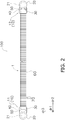
- Fig. 2 is a schematic view of the heat exchanger 100 as seen from the first direction dr1.
- the heat exchanger 100 is used for an apparatus that handles a thermal load.
- the heat exchanger 100 is used for a refrigeration apparatus that performs a refrigeration cycle.
- the heat exchanger 100 is used for a refrigeration apparatus that performs a refrigeration cycle whose high-pressure side is in a supercritical state.
- the heat exchanger 100 is used as a heat-source-side heat exchanger and/or a use-side heat exchanger of a refrigeration apparatus.
- the heat exchanger 100 is used for an air-handling unit.
- the heat exchanger 100 is configured to perform heat exchange between a refrigerant and air.
- the heat exchanger 100 can function as an evaporator that evaporates a refrigerant or as a radiator that releases heat from a refrigerant.
- the meaning of the term "radiator” includes the meaning of a condenser that condenses a refrigerant.
- Examples of a refrigerant used in the heat exchanger 100 include a high-pressure refrigerant such as CO 2 refrigerant.
- the heat exchanger 100 includes a heat exchange unit 1 between both end portions thereof.
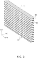
- Fig. 3 is a schematic view of the heat exchange unit 1.
- the heat exchange unit 1 occupies the most part of the heat exchanger 100.
- the heat exchanger 100 performs heat exchange between a refrigerant and air mainly in the heat exchange unit 1.
- the heat exchanger 100 is configured, for example, so that a refrigerant and air exchange heat when airflow generated by a fan passes through the heat exchange unit 1.
- the configuration of the heat exchange unit 1 may be changed as appropriate in accordance with design specifications.
- the heat exchange unit 1 may be configured to extend in a single direction (here, the second direction dr2) as seen from the first direction dr1.
- the heat exchange unit 1 may be configured to extend in the second direction dr2 as seen from the first direction dr1 and then be bent and extend in the third direction dr3.
- the heat exchange unit 1 may be substantially I-shaped, substantially L-shaped, substantially U-shaped, or polygonal as seen from the first direction dr1. That is, the heat exchange unit 1 may have a single surface or may have a plurality of surfaces.
- the heat exchanger 100 includes a plurality of headers 10, a plurality of heat transfer tubes 60, and a plurality of heat transfer fins 70.
- the first direction dr1 corresponds to the longitudinal direction of the header 10. That is, the header 10 extends in the first direction dr1.
- the header 10 is connected to end portions of the plurality of heat transfer tubes 60.
- the heat exchanger 100 includes a pair of headers 10. To be specific, the heat exchanger 100 includes, as the header 10, a first header 11 and a second header 12.
- One of the first header 11 and the second header 12 is disposed at one end of the heat exchanger 100 in the second direction dr2.
- the other of the first header 11 and the second header 12 is disposed at the other end of the heat exchanger 100 in the second direction dr2.
- One of the first header 11 and the second header 12 functions as a collecting header that merges refrigerants flowing out from the plurality of heat transfer tubes 60.
- the other of the first header 11 and the second header 12 functions as a diverting header that distributes refrigerants to the plurality of heat transfer tubes 60.
- the first header 11 or the second header 12 corresponds to an inlet header including a refrigerant inlet part of the heat exchanger 100.
- An inlet pipe (not shown) for feeding a refrigerant to the heat exchanger 100 is connected to the inlet header.
- the first header 11 or the second header 12 corresponds to an outlet header including a refrigerant outlet part of the heat exchanger 100.
- An outlet pipe (not shown) for feeding a refrigerant, which flows out of the heat exchanger 100, to another part is connected to the outlet header. Details of the configuration of the header 10 will be described below.
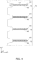
- Fig. 4 is a sectional view taken along line A-A of Fig. 1 .
- the plurality of heat transfer tubes 60 are arranged at intervals in the first direction dr1.
- the second direction dr2 corresponds to the longitudinal direction. That is, the heat transfer tube 60 extends in the second direction dr2.
- the heat transfer tube 60 is a flat tube having a flat shape.
- the first direction dr1 corresponds to the thickness direction
- the third direction dr3 corresponds to the width direction.
- the heat transfer tube 60 has a width having a length LA.
- the heat transfer tube 60 has a thickness having a length LB.
- One end of each heat transfer tube 60 is connected to the first header 11. The other end of each heat transfer tube 60 is connected to the second header 12.
- a refrigerant flows through the inside of the heat transfer tube 60.
- a flow path 65 extending from one end to the other end in the longitudinal direction is formed.
- a plurality of flow paths 65 are formed in each heat transfer tube 60.
- the plurality of flow paths 65 are arranged in the width direction. That is, the heat transfer tube 60 is a so-called flat multi-hole tube.
- the heat transfer tube 60 is made of aluminum or an aluminum alloy.
- Each flow path 65 of the heat transfer tube 60 communicates with the space in the header 10.
- the heat transfer fin 70 is a member that accelerates heat exchange between air and a refrigerant in the heat transfer tube 60.
- the heat transfer fin 70 is a plate-shaped member that increases the heat exchange area in which the heat transfer tube 60 and air exchanges heat.
- the first direction dr1 corresponds to the longitudinal direction. That is, the heat transfer fin 70 extends in the longitudinal direction of the header 10.
- the heat transfer fin 70 extends also in a direction crossing the longitudinal direction of the heat transfer tube 60.
- a plurality of cutouts 75 are formed in the heat transfer fin 70.
- the plurality of cutouts 75 are arranged in the heat transfer fin 70 at intervals in the longitudinal direction. Each cutout 75 extends in the width direction of the heat transfer tube 60.
- the heat transfer tube 60 is inserted into each cutout 75 of the heat transfer fin 70.
- the heat transfer fin 70 is in contact with the heat transfer tube 60 at an edge portion of each cutout 75.
- the heat transfer fin 70 is made of aluminum or an aluminum alloy.
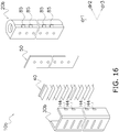
- Fig. 5 is an exploded schematic view of the header 10.
- Fig. 6 is a sectional view taken along line B-B of Fig. 1 .
- Fig. 7 is a sectional view taken along line C-C of Fig. 6 .
- the header 10 mainly includes a header body 20, a header first member 30, a header second member 40, and a header third member 50.
- the header 10 is formed by joining the header body 20, the header first member 30, the header second member 40, and the header third member 50.
- These constituent members of the header 10 are made of aluminum or an aluminum alloy.
- the longitudinal direction of each of these members is the first direction dr1.
- the meaning of the term "join" includes the meaning that members are fixed to each other by brazing.
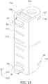
- Fig. 8 is a schematic view of the header body 20.
- the header body 20 is a member having a tubular shape.
- the longitudinal direction of the header body 20 corresponds to the first direction dr1. That is, the header body 20 extends in the first direction dr1.
- the header body 20 is substantially cylindrical. To be more specific, the header body 20 has a substantially ⁇ -shaped cross section.
- a cylindrical space (a body inner space S1) is formed in the header body 20.
- the body inner space S1 extends in the longitudinal direction of the header 10.
- the first hole H1 is a hole that allows the body inner space S1 and a heat-transfer-tube insertion space S2, which is formed by the header first member 30 and the header second member 40, to communicate with each other. That is, the first hole H1 forms a communication flow path CP1 through which the body inner space S1 and the heat-transfer-tube insertion space S2 (first space) communicate with each other.
- the first hole H1 extends in the second direction dr2 between the body inner space S1 and the heat-transfer-tube insertion space S2.
- the first holes H1 are arranged at intervals in the first direction dr1.
- the first hole H1 is substantially circular as seen from the second direction dr2.
- the header body 20 mainly includes a body portion 21 and a communication portion 25.
- the body portion 21 and the communication portion 25 are integrally formed. Although there is no clear boundary between the body portion 21 and the communication portion 25, for convenience of description, a part positioned on the heat exchange unit 1 side with respect to a two-dot chain line D of Fig. 6 is defined as the communication portion 25 and a part positioned on the opposite side is defined as the body portion 21. That is, the body portion 21 is positioned on the opposite side of the heat transfer tube 60 relative to the communication portion 25.
- the body portion 21 has a substantially C-shaped cross section (see Fig. 6 ).
- the body inner space S1 is mainly formed inside of the body portion 21.
- the body inner space S1 is formed by the body portion 21.
- the thickness of the body portion 21 extends in the radial direction of the body inner space S1 (the radial direction from the center of the body inner space S1).
- the body portion 21 has a thickness having a length L1. In the present embodiment, the length L1 is 5 mm.
- an inlet pipe (not shown) for feeding a refrigerant to the heat exchanger 100 is connected to the header 10, which is the inlet header.
- the inlet pipe is connected to the body portion 21.
- An outlet pipe (not shown) for feeding a refrigerant, which flows out from the heat exchanger 100, to another part is connected to the header 10, which is the outlet header.
- the outlet pipe is connected to the body portion 21.
- a hole for connecting the inlet pipe and/or the outlet pipe is formed, for example, in a top part or a bottom part of the body portion 21 or on a side opposite to the communication portion 25.
- the communication portion 25 is substantially I-shaped as seen from the first direction dr1 (see Fig. 6 ).
- the plurality of first holes H1 are formed in the communication portion 25.
- the thickness of the communication portion 25 extends in the second direction dr2.
- the communication portion 25 has a thickness having a length L2.
- the length L2 is 3 mm.
- the communication portion 25 extends in the third direction dr3 as seen from the first direction dr1.
- the width of the communication portion 25 extends in the third direction dr3.
- the communication portion 25 has a width having a length L3.
- the length L3 is greater than the length LA of the heat transfer tube 60 in the width direction. In the present embodiment, the length L3 is 8 mm.
- the plurality of first holes H1 are arranged in the communication portion 25 at intervals in the first direction dr1.
- the first hole H1 extends in the second direction dr2 through the communication portion 25.
- One end of each first hole H1 communicates with the body inner space S1.
- the other end of the first hole H1 communicates with a second hole H2 formed in the header third member 50.
- the length of the first hole H1 in the third direction dr3 corresponds to a length La (see Fig. 6 ).
- the length of the first hole H1 in first direction dr1 corresponds to a length Lb (see Fig. 7 ).
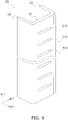
- Fig. 9 is a schematic view of the header first member 30.
- the header first member 30 is a plate-shaped part having the longitudinal direction in the first direction dr1. That is, the header first member 30 is a member that extends in the first direction dr1.
- the header first member 30 is substantially U-shaped as seen from the first direction dr1.
- An end portion of each heat transfer tube 60 is inserted into the header first member 30. It can be said that the header first member 30 is a member that surrounds a tip end of the heat transfer tube 60.
- the header first member 30 forms, inside thereof, the heat-transfer-tube insertion space S2 together with the header second member 40. In other words, the header first member 30 covers the heat-transfer-tube insertion space S2.
- the header first member 30 is made of a so-called cladding material and includes a brazing material on the surface side. In relation to this, the header first member 30 functions as a joining member that joins some or all of the header body 20, the header second member 40, the header third member 50, and each heat transfer tube 60.
- the header first member 30 mainly includes a first surrounding portion 31, a second surrounding portion 32, and a third surrounding portion 33.
- the first surrounding portion 31, the second surrounding portion 32, and the third surrounding portion 33 are integrally formed.
- a part positioned on the heat exchange unit 1 side with respect to a two-dot chain line E in Fig. 6 is defined as the first surrounding portion 31 and parts positioned on the opposite side are defined as the second surrounding portion 32 and the third surrounding portion 33.
- the first surrounding portion 31 (a first portion) has the longitudinal direction in the first direction dr1.
- the first surrounding portion 31 extends in the third direction dr3 as seen from the first direction dr1.
- the first surrounding portion 31 is a plate-shaped part.
- the thickness of the first surrounding portion 31 extends in the second direction dr2.
- the first surrounding portion 31 has a main surface facing in the second direction dr2.
- the main surface of the first surrounding portion 31 is positioned closest to the heat exchange unit 1 side in the header 10. In other words, the first surrounding portion 31 is positioned closer to the heat transfer tube 60 side than the other members.
- a plurality of heat-transfer-tube insertion holes 310 into which end portions of the heat transfer tubes 60 are inserted, are formed.
- the plurality of heat-transfer-tube insertion holes 310 are arranged in the header first member 30 at intervals in the first direction dr1.
- the heat-transfer-tube insertion hole 310 has a shape that traces the shape of the heat transfer tube 60 as seen from the second direction dr2.
- One end of each of the plurality of heat transfer tubes 60 extends through the first surrounding portion 31 via the heat-transfer-tube insertion hole 310.
- the first surrounding portion 31 engages the heat transfer tube at an edge portion of the heat-transfer-tube insertion hole 310.
- the first surrounding portion 31 supports one end side of the heat transfer tube 60.
- the second surrounding portion 32 and the third surrounding portion 33 extend in the second direction dr2 from both ends of the first surrounding portion 31 in the transversal direction (here, the third direction dr3).
- the second surrounding portion 32 has the longitudinal direction in the first direction dr1.
- the second surrounding portion 32 is connected to one end side of the first surrounding portion 31 as seen from the first direction dr1 and extends toward the header body 20 side in the second direction dr2.
- the second surrounding portion 32 is a plate-shaped part.
- the thickness of the second surrounding portion 32 extends in the third direction dr3.
- the second surrounding portion 32 is positioned outside of one end of the heat transfer tube 60 in the third direction dr3.
- the second surrounding portion 32 has a main surface facing in the third direction dr3.
- the second surrounding portion 32 is joined, inside thereof, to the header body 20, the header second member 40, and the header third member 50.
- the third surrounding portion 33 has the longitudinal direction in the first direction dr1.
- the third surrounding portion 33 is connected to the other end side of the first surrounding portion 31 as seen from the first direction dr1 and extends toward the header body 20 side in the second direction dr2.
- the third surrounding portion 33 is a plate-shaped part. That is, the thickness of the third surrounding portion 33 extends in the third direction dr3.
- the third surrounding portion 33 is positioned outside of the other end of the heat transfer tube 60 in the third direction dr3.
- the third surrounding portion 33 is positioned on a side opposite to the second surrounding portion 32 with protruding portions 45 (described below) of the header second member 40 therebetween.
- the third surrounding portion 33 has a main surface facing in the third direction dr3.
- the third surrounding portion 33 is joined, inside thereof, to the header body 20, the header second member 40, and the header third member 50.
- a clearance is left between the heat transfer tube 60 inserted into the heat-transfer-tube insertion space S2, and the second surrounding portion 32 and the third surrounding portion 33.
- the brazing material is prevented from flowing from the second surrounding portion 32 and the third surrounding portion 33 to an end of the heat transfer tube 60.
- the flow path 65 of the heat transfer tube 60 is prevented from becoming blocked by the brazing material.
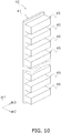
- Fig. 10 is a schematic view of the header second member 40.
- Fig. 11 is a schematic view of the header second member 40 as seen from the third direction dr3.
- Fig. 12 is a schematic view of the header second member 40 as seen from the heat exchange unit 1 side.
- the header second member 40 is positioned between the header body 20 and the header first member 30. To be more specific, the header second member 40 is positioned between the header third member 50 and the first surrounding portion 31 of the header first member 30. As illustrated in Figs. 10 to 12 , the header second member 40 has a ladder-like shape. In other words, the header second member 40 is shaped like a heat sink having heat radiation fins for cooling a heat-generating component.
- the header second member 40 includes a base portion 41 and a plurality of protruding portions 45.
- the base portion 41 and the protruding portions 45 are integrally formed. Although there is no clear boundary between the base portion 41 and the protruding portions 45, for convenience of description, a flat plate-shaped part is defined as the base portion 41 and parts that protrude toward the heat exchange unit 1 side are defined as the protruding portions 45.
- the base portion 41 is a plate-shaped part having the longitudinal direction in the first direction dr1. That is, the base portion 41 is a member that extends in the first direction dr1. The base portion 41 extends in the third direction dr3 as seen from the first direction dr1. In other words, the width of the base portion 41 extends in the third direction dr3. The length of the base portion 41 in the width direction is substantially the same as the length of the communication portion 25 in the width direction. That is, the base portion 41 has a width having the length L3. The thickness of the base portion 41 extends in the second direction dr2. The base portion 41 has a thickness having a length L4. The length L4 is 2 mm. A through hole (a communication hole Ha) is formed in the base portion 41.
- the communication hole Ha is a hole that allows the communication flow path CP1, which is connected to the body inner space S1, and the heat-transfer-tube insertion space S2 to communicate with each other.
- the communication hole Ha extends in the second direction dr2 between the body inner space S1 and the heat-transfer-tube insertion space S2.
- a plurality of communication holes Ha are formed in the base portion 41.
- the number of communication holes Ha is the same as the number of heat transfer tubes 60 inserted into the header first member 30.
- the plurality of communication holes Ha are arranged in the base portion 41 at intervals in the first direction dr1.
- the communication hole Ha extends in the second direction dr2 through the base portion 41.
- the length of the communication hole Ha in the third direction dr3 corresponds to a length Lc (see Fig. 6 ).
- the length Lc is greater than the length La or Le (described below).
- the length of the communication hole Ha in the first direction dr1 corresponds to a length Ld (see Fig. 7 ).
- the length Ld is greater than the length Lb or Lf (described below).
- One end of the communication hole Ha communicates with the communication flow path CP1.
- the other end of the communication hole Ha communicates with the heat-transfer-tube insertion space S2 formed in the header first member 30. That is, the communication hole Ha allows the body inner space S1 and the heat-transfer-tube insertion space S2 to communicate with each other via the communication flow path CP1.
- the communication hole H is substantially rectangular as seen from the heat exchange unit 1 side. As seen from the second direction dr2, the area of the communication hole Ha is greater than the total area of the flow paths 65 formed in one heat transfer tube 60. In other words, the area of the communication hole Ha is greater than the cross-sectional area of a refrigerant flow paths formed in the heat transfer tube 60.
- an edge part (an edge portion 411) of the communication hole Ha is chamfered. That is, a part of the edge portion 411 that forms the communication hole Ha of the base portion 41, the part being positioned on the heat transfer tube 60 side, is chamfered.
- the edge portion 411 is chamfered in such a way that, from the heat exchange unit 1 side toward the header body 20 side, the edge portion 411 becomes narrower than the length LA in the width direction and/or the length LB in the thickness direction of the heat transfer tube 60. In relation to this, a tip end of the heat transfer tube 60 cannot enter into the body inner space S1 side further than the edge portion 411.
- the protruding portion 45 is a part that protrudes from the base portion 41 toward the heat exchange unit 1 side in the second direction dr2. To be more specific, the protruding portion 45 extends from the base portion 41 toward an inner surface 311 of the first surrounding portion 31 of the header first member 30 in the second direction dr2. In a state of being set, the protruding portions 45 are adjacent to each other and are arranged outside of the heat transfer tube 60 in the first direction dr1 at intervals. To be more specific, each protruding portion 45 is disposed in such a way that an end portion of the heat transfer tube 60 is interposed between the protruding portion 45 and another protruding portion 45 that is adjacent thereto in the first direction dr1 via a gap.
- the protruding portion 45 extends in the second direction dr2 as seen from the first direction dr1. That is, the protruding direction (extension direction) of the protruding portion 45 is the second direction dr2.
- the protruding portion 45 has a length L5 in the second direction dr2. In the present embodiment, the length L5 is 7 mm. That is, the length of the protruding portion 45 in the second direction dr2 is greater than or equal to 2 mm.
- the length of the protruding portion 45 in the second direction dr2 is greater than or equal to twice the length L4 of the base portion 41 in the width direction (the second direction dr2).
- the width of the protruding portion 45 extends in the third direction dr3.
- the length of the protruding portion 45 in the width direction is substantially the same as the length of the base portion 41 in the width direction. That is, the protruding portion 45 has a width having the length L3.
- the length L3 is greater than the length LA of the heat transfer tube 60 in the width direction. That is, the width of the protruding portion 45 is greater than the width of the heat transfer tube 60.
- the thickness of the protruding portion 45 extends in the first direction dr1.
- the protruding portion 45 has a thickness having a length L6.
- the length L6 is greater than the length L4.
- the thickness of the base portion 41 is less than the thickness of the protruding portion 45.
- the length L6 is 4 mm.
- the thickness (L6) of the protruding portion 45 is greater than or equal to twice the thickness (L4) of the base portion 41.
- Each protruding portion 45 is adjacent to another protruding portion 45 at an interval corresponding to a length L7 in the first direction dr1. That is, the protruding portions 45 are arranged in the base portion 41 at intervals corresponding to the length L7 in the first direction dr1. In the present embodiment, the length L7 is 4 mm. That is, in the present embodiment, the plurality of protruding portions 45 are arranged in the first direction dr1 at intervals greater than or equal to 1 mm.
- Each protruding portion 45 is in contact with the header first member 30.
- each protruding portion 45 is joined to the header first member 30.
- a tip end part of each protruding portion 45 is joined to the inner surface 311 of the first surrounding portion 31.
- a part of each protruding portion 45 facing in the third direction dr3 is joined to an inner surface 321 of the second surrounding portion 32 or an inner surface 331 of the third surrounding portion 33.
- the header second member 40 which includes such protruding portions 45, functions as a partitioning member that divides the space in the header 10 into a plurality of spaces (heat-transfer-tube insertion spaces S2). That is, in the header 10, because the plurality of protruding portions 45 are arranged at intervals in the first direction dr1, a plurality of heat-transfer-tube insertion spaces S2 are arranged in the first direction dr1. That is, the header second member 40 is a member for forming a plurality of spaces in the header 10.
- the header second member 40 also functions as a spacer member that provides an appropriate insertion length of the heat transfer tube 60 inserted into the header first member 30. That is, because the protruding portion 45, which extends from the base portion 41 toward the first surrounding portion 31 of the header first member 30 in the second direction dr2, is provided, the first surrounding portion 31 and the base portion 41 are prevented from becoming close to each other, and a space corresponding to the length L5 is formed between the first surrounding portion 31 and the base portion 41. In relation to this, when the heat transfer tube 60 is inserted into the header first member 30, an appropriate insertion length is provided. As a result, extraction of the heat transfer tube 60 inserted into the header first member 30 is prevented.
- FIGs. 6 and 7 illustrate a state in which, in the header 10 in a completed state, an insertion length having a length LX of the heat transfer tube 60 is provided.
- a tip end part of the heat transfer tube 60 inserted into the heat-transfer-tube insertion space S2 is suppressed from becoming close to a member including a brazing material (here, the header first member 30 or the header third member 50). Therefore, in the brazing step, the brazing material is not likely to reach the tip end part of the heat transfer tube 60. As a result, the flow path 65 of the heat transfer tube 60 is prevented from becoming blocked by the brazing material.
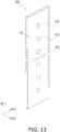
- Fig. 13 is a schematic view of the header third member 50.
- the header third member 50 is a plate-shaped part having the longitudinal direction in the first direction dr1. That is, the header third member 50 extends in the first direction dr1.
- the header third member 50 is positioned between the header body 20 and the header second member 40.
- the header third member 50 is made of a so-called cladding material and includes a brazing material on the surface side.
- the header third member 50 functions as a joining member that joins the header body 20 and the base portion 41 of the header second member 40.
- the brazing material is disposed between the header body 20 and the base portion 41.
- the header third member 50 extends in the third direction dr3 as seen from the first direction dr1.
- the width of the header third member 50 extends in the third direction dr3.
- the length of the header third member 50 in the width direction is substantially the same as the length of the communication portion 25 of the header body 20 in the width direction. That is, the header third member 50 has a width having the length L3.
- the thickness of the header third member 50 extends in the second direction dr2.
- the header third member 50 has a thickness having a length L8. In the present embodiment, the length L8 is 2.5 mm.
- a plurality of through holes (second holes H2) are formed in the header third member 50.
- the second hole H2 is a hole that allows, together with the first hole H1, the body inner space S1 and the heat-transfer-tube insertion space S2, which is formed by the header first member 30 and the header second member 40, to communicate with each other. That is, the second hole H2 forms the communication flow path CP1 together with the first hole H1.
- the second hole H2 extends in the second direction dr2 between the body inner space S1 and the heat-transfer-tube insertion space S2.
- the second holes H2 are arranged at intervals in the first direction dr1.
- the second hole H2 extends in the second direction dr2 through the header third member 50. One end of the second hole H2 communicates with the first hole H1.
- the other end of the second hole H2 communicates with the communication hole Ha formed in the header second member 40.
- the length of the second hole H2 in the third direction dr3 corresponds to the length Le (see Fig. 6 ).
- the length of the second hole H2 in the first direction dr1 corresponds to the length Lf (see Fig. 7 ).
- the second hole H2 has the same size and the same shape as the first hole H1 as seen from the second direction dr2. That is, as with the first hole H1, the second hole H2 is substantially circular as seen from the second direction dr2.
- the length La of the first hole H1 in the third direction dr3 and the length Le of the second hole H2 in the third direction dr3 are equal.
- the length Lb of the first hole H1 in first direction dr1 and the length Lf of the second hole H2 in the third direction dr3 are equal. Therefore, the pressure resistance of the header 10 is improved.
- the meaning of the term “equal” includes not only the meaning of "completely equal” but also the meaning of "substantially equal” with a predetermined tolerance. For example, when the size and magnitude of the second hole H2 coincide with those of the first hole H1 by 80 percent or more as seen from the second direction dr2, the second hole H2 has the same size and the same shape as the first hole H1 as seen from the second direction dr2.
- the second hole H2 overlaps a corresponding first hole H1 as seen from the second direction dr2.
- the position of the second hole H2 is the same as the position of the corresponding first holes H1 as seen from the second direction dr2.
- the meaning of the term “the same” includes not only the meaning of “completely the same” but also the meaning of "substantially the same” with a predetermined tolerance.
- the second hole H2 is disposed at the same position as the first hole H1 as seen from the second direction dr2.
- the header third member 50 is in contact with the communication portion 25 of the header body 20 and the base portion 41 of the header second member 40.
- a surface of the header third member 50 on the header body 20 side is joined to the communication portion 25.
- a surface of the header third member 50 on the heat exchange unit 1 side is joined to the base portion 41 of the header second member 40.
- the body inner space S1 which has a cylindrical shape and extends in the first direction dr1, is formed in the header body 20 of the header 10.
- the body inner space S1 communicates with the plurality of first holes H1. That is, the body inner space S1 communicates with a plurality of communication flow paths CP1.
- the body inner space S1 communicates with the inlet pipe and/or the outlet pipe.
- the plurality of heat-transfer-tube insertion spaces S2 are formed in the header 10.
- Each heat-transfer-tube insertion space S2 is formed by being surrounded by the header first member 30 and the header second member 40.
- the heat-transfer-tube insertion space S2 is a space surrounded by the base portion 41, the protruding portions 45 that are adjacent to each other, and the inner surface 311 of the first surrounding portion 31, the inner surface 321 of the second surrounding portion 32, and the inner surface 331 of the third surrounding portion 33 of the header first member 30.
- the plurality of heat-transfer-tube insertion spaces S2 are arranged in the first direction dr1.
- the length of the heat-transfer-tube insertion space S2 in the third direction dr3 is greater than the length of the heat transfer tube 60 in the third direction dr3.
- One end of a corresponding one of the heat transfer tubes 60 is inserted into the heat-transfer-tube insertion space S2. That is, the heat-transfer-tube insertion space S2 communicates with the flow paths 65 of the heat transfer tube 60.
- the heat-transfer-tube insertion space S2 communicates with a corresponding one of the second holes H2 via the communication hole Ha formed in the base portion 41. That is, the heat-transfer-tube insertion space S2 communicates with a corresponding one of the communication flow paths CP1.
- the plurality of communication flow paths CP1 which allow the body inner space S1 and the heat-transfer-tube insertion space S2 to communicate with each other, are formed.
- the plurality of communication flow paths CP1 are arranged in the first direction dr1.
- One end of each communication flow path CP1 communicates with the body inner space S1, and the other end of the communication flow path CP1 communicates with any one of the communication holes Ha.
- the communication flow path CP1 allows the body inner space S1 and the heat-transfer-tube insertion space S2 to communicate with each other via a corresponding one of the communication holes Ha. That is, the body inner space S1 and each heat-transfer-tube insertion space S2 communicate with each other via a corresponding one of the communication flow paths CP1 and a corresponding one of the communication holes Ha.
- the refrigerant flows into the heat exchanger 100 via an inlet pipe (not shown).
- the refrigerant flows into the body inner space S1 of the inlet header via the inlet pipe.
- the refrigerant flowed into the body inner space S1 diverges and flows into any one of the communication flow paths CP1.
- the refrigerant flowed through the communication flow path CP1 flows into the heat-transfer-tube insertion space S2 communicating with the refrigerant communication flow path CP1.
- the refrigerant flowed into the heat-transfer-tube insertion space S2 flows into each flow path 65 of the heat transfer tube 60 inserted into the heat-transfer-tube insertion space S2.
- the refrigerant flowed into the flow paths 65 of the heat transfer tube 60 flows through the heat exchange unit 1, and exchanges heat with air passing through the heat exchange unit 1.
- the refrigerant flowed through the heat exchange unit 1 flows into the heat-transfer-tube insertion space S2 of the outlet header.
- the refrigerant flowed into the heat-transfer-tube insertion space S2 flows into the communication flow path CP1 communicating with the heat-transfer-tube insertion space S2.
- the refrigerant flowed through the communication flow path CP1 flows into the body inner space S1.
- the refrigerant flowed into the body inner space S1 via the heat-transfer-tube insertion space S2 and the communication flow path CP1 merges with a refrigerant flowed into the body inner space S1 through other heat-transfer-tube insertion spaces S2 and other communication flow paths CP1, and flows out to an outlet pipe (not shown).
- the header body 20 is formed by extrusion. In relation to this, the body portion 21 and the communication portion 25 are integrally formed.
- the header second member 40 is formed by extrusion. In relation to this, the base portion 41 and each protruding portion 45 are integrally formed.
- the header body 20 and the header first member 30 are temporarily fixed to each other, with the header second member 40 and the header third member 50 interposed therebetween. Due to the temporal fixture, in a completed state, the body portion 21, the communication portion 25, the header third member 50, the base portion 41, each protruding portion 45, and the first surrounding portion 31 are arranged in order in the second direction dr2; and the outside in the third direction dr3 of the communication portion 25, the header third member 50, the base portion 41, and each protruding portion 45 is covered by the second surrounding portion 32 and the third surrounding portion 33.
- the header third member 50 which is made of a cladding material, is positioned between the header body 20 and the header second member 40.
- the brazing material is disposed between the header body 20 and the header second member 40.
- the header first member 30, which is made of a cladding material, is disposed outside in the third direction dr3 of the communication portion 25, the header third member 50, the base portion 41, and each protruding portion 45. That is, the brazing material is disposed outside in the third direction dr3 of the communication portion 25, the header third member 50, the base portion 41, and each protruding portion 45.
- the plurality of heat transfer tubes 60 are inserted into the header 10 in the assembled state via the heat-transfer-tube insertion holes 310. Both headers 10 and the heat exchange unit 1, which are in a coupled state, are conveyed into a furnace and brazed in the furnace, and thereby the parts are joined to each other.
- the heat transfer tube 60 is directly inserted into the header body as in the existing technology (such as PTL 1) without using other members, a tip end of the heat transfer tube protrudes into the body inner space.
- pressure loss in the body inner space increases due to the presence of the tip end of the heat transfer tube.
- the pressure loss increases significantly when a high-pressure refrigerant such as CO 2 refrigerant flows in the body inner space.
- the heat transfer tube 60 is not configured to be directly inserted into the body inner space S1 of the header body 20.
- the heat-transfer-tube insertion space S2 into which the heat transfer tube 60 is inserted, is formed by the header first member 30 and the like.
- the body inner space S1 in which the refrigerant flows in the first direction dr1, and the heat-transfer-tube insertion space S2, into which the heat transfer tube 60 is inserted, are separated from each other. Therefore, increase of pressure loss described above is prevented.
- the length L2 of the communication portion 25 of the header body 20 in the thickness direction is 3 mm. That is, the thickness of the communication portion 25 is less than or equal to 4 mm. Therefore, it is easy to perform a step of forming the first hole H1. That is, because the thickness of the communication portion 25 is less than or equal to 4 mm, increase of time, manpower, and/or cost related to the step of forming the first holes H1 is prevented, whereas the time, manpower, and/or cost may increase if the thickness of the communication portion 25 is greater than 4 mm. In particular, because the thickness of the communication portion 25 is less than or equal to 3 mm, it is easy to form the first hole H1 by using a press-working method that excels in mass productivity. Regarding the step of forming the first hole H1, time, manpower, and/or cost is reduced. In relation to this, mass productivity is improved.
- the length L8 of the header third member 50 in the thickness direction is 2.5 mm. That is, the thickness of the header third member 50 is less than or equal to 4 mm. Therefore, it is easy to perform a step of forming the second hole H2. That is, because the thickness of the header third member 50 is less than or equal to 4 mm, increase of time, manpower, and/or cost related to the step of forming the second hole H2 is prevented, whereas the time, manpower, and/or cost may increase if the thickness of the header third member 50 is greater than 4 mm. In particular, it is easy to form the second hole H2 by using a press-working method that excels in mass productivity. Regarding the step of forming the second hole H2, time, manpower, and/or cost is prevented.
- the protruding portion 45 which extends from the base portion 41 toward the first surrounding portion 31 of the header first member 30 in the second direction dr2, is provided, the first surrounding portion 31 and the base portion 41 are prevented from becoming close to each other, and a space corresponding to the length L5 is formed between the first surrounding portion 31 and the base portion 41.
- an appropriate insertion length is provided when the heat transfer tube 60 is inserted into the header first member 30, an appropriate insertion length is provided.
- extraction of the heat transfer tube 60inserted into the header first member 30 is prevented.
- the heat exchanger 100 is brazed in a furnace, extraction of the end portion of the heat transfer tube 60 from the header first member 30 due to thermal expansion or thermal contraction is prevented.
- the brazing material is not likely to reach the tip end part of the heat transfer tube 60.
- the flow paths 65 of the heat transfer tube 60 are prevented from becoming blocked by the brazing material.
- the reliability of the heat exchanger 100 is improved.
- a plurality of spaces are formed in the header 10 by the plurality of protruding portions 45 of the header second member 40.
- a refrigerant can more smoothly flow through the heat exchanger 100, and heat exchange in the heat exchange unit 1 can be more appropriately performed.
- the reliability of the heat exchanger 100 is improved.
- the header 10 includes the header body 20 having a tubular shape, the header first member 30 through which one end of each of the plurality of heat transfer tubes 60 extends, and the header second member 40 positioned between the header body 20 and the header first member 30 in the second direction dr2.
- the header second member 40 includes the base portion 41 extending in the first direction dr1 and the plurality of protruding portions 45 extending from the base portion 41 toward the header first member 30 in the second direction dr2.
- the insertion length of the heat transfer tube 60 inserted into the header 10 can be more easily provided.
- extraction of the heat transfer tube 60, which is inserted into the header 10, from the header 10 can be prevented.
- members are fixed to each other by brazing, extraction of the heat transfer tube 60 from the header 10 after finishing the brazing step is prevented.
- the heat exchanger 100 excels in ease of assembly.
- the protruding portion 45 is joined to the header first member 30. Therefore, the protruding portion 45 is firmly fixed to the header first member 30, and the insertion length of the heat transfer tube 60 inserted into the header 10 can be more reliably and appropriately provided.
- the length L5 of the protruding portion 45 in the second direction dr2 is greater than or equal to 2 mm. That is, the length of the protruding portion 45 in the second direction dr2 is set to a length that is necessary to provide an appropriate insertion length of the heat transfer tube 60 into the header 10. In particular, when members are fixed to each other by brazing, the length of the protruding portion 45 in the second direction dr2 is set so as to provide an insertion length with which extraction of the heat transfer tube 60 from the header 10 due to thermal expansion or thermal contraction is prevented.
- the plurality of protruding portions 45 are arranged in the first direction dr1 at intervals greater than or equal to 1 mm. Therefore, when members are fixed to each other by brazing, local accumulation of a brazing material in the header 10 is prevented.
- the length (L3) of the heat-transfer-tube insertion space S2, which is surrounded by the base portion 41 and the protruding portions 45 that are adjacent to each other, in the third direction dr3 is greater than the length (LA) of the heat transfer tube 60 in the third direction dr3. Therefore, a tip end of the heat transfer tube 60 is prevented from being in contact with the member which is positioned outside of the heat-transfer-tube insertion space S2 in the third direction dr3 and covers the heat-transfer-tube insertion space S2. In relation to this, the posture of the heat transfer tube 60 inserted into the heat-transfer-tube insertion space S2 is prevented from becoming unstable. In the brazing step, blocking of the flow paths 65 of the heat transfer tube 60 by a brazing material, which may occur if the brazing material flows from the second surrounding portion 32 or the third surrounding portion 33 to a tip end of the heat transfer tube 60, is prevented.
- the header first member 30 covers the heat-transfer-tube insertion space S2. That is, the header first member 30 has a function of supporting the heat transfer tube 60 and a function of forming the heat-transfer-tube insertion space S2.
- increase in the number of constituent members of the header 10 is reduced. Therefore, cost is reduced.
- the communication hole Ha which allows the heat-transfer-tube insertion space S2 and the body inner space S1 to communicate with each other, is formed. Therefore, the heat-transfer-tube insertion space S2, which is surrounded by the base portion 41 and the protruding portions 45 that are adjacent to each other, and the body inner space S1 communicate with each other, and a refrigerant flow path is formed between the heat-transfer-tube insertion space S2 and the body inner space S1.
- the edge portion 411 of the communication hole Ha is chamfered at a surface of the base portion 41 on the heat exchange unit 1 side. That is, a part of the edge portion 411, which forms the communication hole Ha of the base portion 41, the part being positioned on the heat transfer tube 60 side, is chamfered. Therefore, during assembly of the heat exchanger 100, it is possible to perform temporary fixing by pressing a tip end of the heat transfer tube 60 against the edge portion 411. Thus, it is easy to make the insertion lengths of the heat transfer tubes 60 uniform, and it is easy to assemble the heat exchanger 100.
- the area of the communication hole Ha is greater than the cross-sectional area of all refrigerant flow paths formed in the heat transfer tube 60. Therefore, a large refrigerant flow path is formed between the body inner space S1 and the heat transfer tube 60 inserted into the heat-transfer-tube insertion space S2. As a result, pressure loss of the refrigerant that passes through the communication hole Ha is reduced.
- the heat transfer tube 60 is a flat tube in which a plurality of refrigerant flow paths 65 are formed. Therefore, regarding a case where the heat transfer tube 60 is a flat tube, which is particularly likely to be extracted from the header 10 during assembly, extraction of the heat transfer tube 60 from the header 10 during assembly is prevented. In particular, extraction of the flat tube is prevented, whereas the flat tube is particularly likely to be extracted from the header 10 due to thermal expansion or thermal contraction when brazing is performed.
- the length L4 of the base portion 41 in the second direction dr2 (thickness direction) is less than the length L6 of the protruding portion 45 in the first direction dr1 (thickness direction). Therefore, it is easy to process the base portion 41. In particular, regarding the base portion 41, it is easy to form the communication hole Ha.
- the length of the protruding portion 45 in the first direction dr1 is greater than or equal to twice the length of the base portion 41 in the second direction. Therefore, it is particularly easy to process the base portion 41.
- the length of the base portion 41 in the second direction dr2 is less than equal to 4 mm. Therefore, regarding the base portion 41, it is possible to form the communication hole Ha by using a press-working method that excels in mass productivity.
- the header second member 40 is formed by extrusion. Therefore, it is easy to produce the header second member 40 including the protruding portion 45. Thus, mass productivity is high.
- the first direction dr1 is the vertical direction. Therefore, ease of assembly of the heat exchanger 100, which includes the header 10 extending in the vertical direction, is improved.
- the brazing material which joins the header body 20 and the base portion 41, is disposed between the header body 20 and the base portion 41.
- the header body 20 and the header second member 40 are joined by brazing.
- the brazing material is disposed between the header body 20 and the base portion 41, during a brazing process, flowing of the brazing material to the heat transfer tube is prevented, and blocking of the flow paths 65 of the heat transfer tube 60 by the brazing material is prevented.
- the header 10 may be configured like a header 10a illustrated in Figs. 14 and 15 .
- the header 10a will be described. Parts whose descriptions are omitted are similar to those of the header 10.
- the header 10a includes a header body 20a, a header first member 30a, a header second member 40a, and a header third member 50a, instead of the header body 20, the header first member 30, the header second member 40, and the header third member 50.
- the header 10a further includes a plurality of penetration members 80.
- the penetration member 80 extends through the header body 20a, the header first member 30a, the header second member 40a, and the header third member 50a in the second direction dr2.
- the penetration member 80 has a plate-like shape.
- the penetration member 80 extends in the second direction dr2.
- the penetration member 80 has a dimension in the second direction dr2 that is sufficient for the penetration member 80 to extend through the header first member 30a, the header second member 40a, and the header third member 50a.
- the penetration member 80 has a length such that the penetration member 80 extends through these members in the second direction dr2 and a tip end part 81 thereof protrudes further.
- through holes H3, through which the penetration members 80 extend are formed in accordance with the number of penetration members 8.
- the shape and size of the through holes H3 are set in accordance with the shape and size of the penetration members 80.
- the members are in a state in which the penetration members 80 extend therethrough via the through holes H3.
- the tip end part 81 of the penetration member 80 which protrudes from the through hole H3 of the first surrounding portion 31 engages with the first surrounding portion 31, and thus the members are firmly and temporarily fixed to each other.
- the penetration member 80 engages with the first surrounding portion 31 as the tip end part 81 is bent.
- the tip end part 81 of the penetration member 80 may be bent, for example, in a manner illustrated in Fig. 15 (see the broken line F in Fig. 15 ).
- the number of penetration members 80 may be changed as appropriate in accordance with design specifications.
- the penetration member 80 may be disposed for each refrigerant path formed in the header 10a.
- the shape and size of the penetration member 80 may be changed as appropriate in accordance with design specifications.
- the penetration member 80 may function as a partitioning member that divides the space in the header.
- the header 10a may be configured so that one penetration member 80 divides the body inner space S1 or the heat-transfer-tube insertion space S2 into two spaces in the first direction dr1.
- the header 10 may be configured like a header 10b illustrated in Figs. 16 and 17 .
- the header 10b will be described. Parts whose descriptions are omitted are similar to those of the header 10.
- the header 10b includes a header body 20b and a header first member 30b, instead of the header body 20 and the header first member 30.
- the header 10b includes ribs 85 (engagement portions).
- the ribs 85 are disposed in the communication portion 25 of the header body 20b.
- the ribs 85 are disposed in both end parts of the communication portion 25 of the header body 20b in the third direction dr3.
- a plurality of ribs 85 are arranged in the first direction dr1 at intervals (see Fig. 16 ).
- the rib 85 has a substantially right-triangular shape as seen from the first direction dr1.
- the rib 85 has a right-triangular shape such that, as seen from the first direction dr1, both ends of the communication portion 25 in the third direction dr3 correspond to the base and the hypotenuse extends from the communication portion 25 side toward the body portion 21 side.
- Engagement holes H4 are formed in the header first member 30b.
- a plurality of engagement holes H4 are formed in the second surrounding portion 32 and the third surrounding portion 33 of the header first member 30b.
- the rib 85 engages with the engagement hole H4.
- the meaning of the phrase “engages with the engagement hole H4" includes the meaning that the rib 85 is fitted into the engagement hole H4.
- the meaning of the phrase "engages with the engagement hole H4" includes the meaning that the rib 85 engages with an edge that forms the engagement hole H4.
- a side of the right-triangular rib 85 connecting the base and the hypotenuse engages with the edge of the engagement hole H4. That is, the rib 85 includes an engagement part that engages with the engagement hole H4.
- Each engagement hole H4 is disposed at a position corresponding to the position of the rib 85 in a state in which the header 10b is temporarily assembled.
- the engagement hole H4 has shape and size such that, in accordance with the shape and size of the rib 85, the rib 85 engages with the edge of the engagement hole H4 in a state in which the header 10b is temporarily assembled.
- the engagement hole H4 is substantially rectangular as seen from the third direction dr3.
- the number of engagement holes H4 corresponds to the number of ribs 85.
- each of the ribs 85 and a corresponding one of the engagement holes H4 engage with each other, and thus the members are firmly and temporarily fixed to each other.
- the meaning of the term “fix” includes the meaning of so-called "interference fit”. That is, in the header 10b, due to the ribs 85 and the engagement holes H4, the members are firmly fixed in a temporarily assembled state. Thus, when assembling the members, it is easy to temporarily fix the members to each other.
- the position of the rib 85 may be changed as appropriate in accordance with design specifications.
- the rib 85 may be disposed in a member other than the communication portion 25.
- the rib 85 may be disposed in the body portion 21.
- the position of the engagement hole H4 may be changed as appropriate in accordance with design specifications.
- the engagement holes H4 corresponding to the ribs 85 may be formed in the communication portion 25 and/or the body portion 21 of the header body 20.
- the number of ribs 85, the shape of each rib 85, the dimensions of each part, and/or the size of each rib 85 may be changed as appropriate in accordance with design specifications.
- the rib 85 may have a shape other than a right-triangular shape as seen from the first direction dr1.
- the rib 85 may have a trapezoidal shape as seen from the first direction dr1.
- the header 10 may be configured like a header 10c illustrated in Figs. 19 to 21 .
- the header 10c will be described. Parts whose descriptions are omitted are similar to those of the header 10.
- the header 10c includes a header body 20c and a header first member 30c, instead of the header body 20 and the header first member 30.
- the shape of the header body 20c differs from that of the header body 20 and is substantially rectangular as seen from the first direction dr1.
- a surface of the header body 20c on the outermost side in the second direction dr2 has a substantially arc-like shape as seen from the first direction dr1. Therefore, the thickness of the header body 20c is reduced.
- a plurality of concave portions 95 (described below), which extend in the first direction dr1, are provided in the surface of the header body 20c on the outermost side in the second direction dr2 (see Fig. 21 ).
- the length of a second surrounding portion (32') and a third surrounding portion (33') of the header first member 30c in the second direction dr2 is greater than that of the header first member 30.
- the length of the second surrounding portion 32' and the third surrounding portion 33' in the second direction dr2 is greater than the length of the header body 20c in the second direction dr2.
- the header first member 30c includes ribs 90.
- the ribs 90 are disposed in the second surrounding portion 32' and the third surrounding portion 33' of the header first member 30c.
- a plurality of ribs 90 are disposed at intervals in the first direction dr1.
- the second surrounding portion 32' and the third surrounding portion 33' extend toward the header body 20c in the second direction dr2 from both ends of the first surrounding portion 31 in the transversal direction (here, the third direction dr3) and have the ribs 90 at tip ends thereof.
- the rib 90 is substantially rectangular as seen from the third direction dr3.
- a plurality of (here, two) concave portions 95 are formed in the body portion 21 of the header body 20c.
- the concave portion 95 is a recessed part that engages with the rib 90.
- the meaning of the term “engage with” includes the meaning of "fit into”.
- the concave portion 95 is positioned in the header body 20c on a side opposite to the header second member 40 in the second direction dr2.
- the concave portion 95 is recessed inward in the second direction dr2 as seen from the first direction dr1.
- the concave portion 95 extends in the body portion 21 in the first direction dr1.
- the concave portion 95 has shape and size such that, in accordance with the shape and size of the rib 90, the rib 90 engages with the edge of the concave portion 95 in a state in which the header 10c is temporarily assembled.
- each of the ribs 90 and a corresponding one of the concave portions 95 engage with each other, and thus the members are crimped to each other.
- each rib 90 is bent toward the concave portion 95 as shown by a two-dot chain line arrow in Fig. 21 , and thereby each rib 90 engages with the concave portion 95.
- each rib 90 is engaged with the concave portion 95, the second surrounding portion 32' and the third surrounding portion 33' having the ribs 90 engage with the header body 20c. Therefore, in a temporarily assembled state, each member is firmly and temporarily fixed. Thus, when assembling the members, it is easy to temporarily fix the members to each other.
- the configurations, such as the shape, dimensions of parts, and size of the header body 20c and/or the header first member 30c may be changed as appropriate in accordance with design specifications.
- the surface of the header body 20c on the outermost side in the second direction dr2 need not have a substantially arc-like shape as seen from the first direction dr1.
- the position of the rib 90 may be changed as appropriate in accordance with design specifications.
- the rib 90 may be disposed in a member other than the second surrounding portion 32' and/or the third surrounding portion 33'.
- the position of the concave portion 95 may be changed as appropriate in accordance with design specifications.
- the number of ribs 90, the shape of each rib 90, the dimensions of each part, and/or the size of each rib 90 may be changed as appropriate in accordance with design specifications.
- the rib 90 may have a shape other than a rectangular shape as seen from the third direction dr3.
- the rib 90 may have a semi-circular shape as seen from the third direction dr3.
- the header body 20 and the header second member 40 are formed by extrusion.
- one or both of the header body 20 and the header second member 40 need not be formed by extrusion and may be formed by using another method.
- the base portion 41 of the header second member 40 and each protruding portion 45 are integrally formed.
- the base portion 41 and each protruding portion need not be integrally formed, and may be configured independently.
- the protruding portion 45 may be disposed as an independent member.
- the header second member 40 which is disposed in the header 10, may be configured by combining a plurality of members. That is, the header second member 40 may be formed by sequentially arranging a plurality of members, each including at least one protruding portion 45 in the first direction dr1.
- the header first member 30 and the header third member 50 include a brazing material and function as joining members that join the members to each other.
- another member including a brazing material may be disposed in the header 10, and the other member may function as a joining member.
- the header 10 may include members that are not described in the above embodiment.
- some of the constituent members of the header 10 described in the above embodiment may be omitted as appropriate.
- the header third member 50 may be omitted as appropriate.
- the protruding portion 45 is joined to the header first member 30.
- the header 10 is configured in such a manner, in order to realize the advantageous effects described in (3-2).
- the protruding portion 45 need not be joined to the header first member 30. Also in such a case, the advantageous effects described in (3-1) can be realized.
- the length L5 of the protruding portion 45 in the second direction dr2 is greater than or equal to 2 mm.
- the length L5 of the protruding portion 45 in the second direction dr2 may be less than 2 mm, provided that the length of the protruding portion 45 in the second direction dr2 allows the insertion length of the heat transfer tube 60 into the header 10 to be appropriately provided. Also in such a case, the advantageous effects described in (3-1) can be realized.
- the header 10 is configured in such a manner, in order to prevent a brazing material from being accumulated locally.
- the plurality of protruding portions 45 need not be arranged at intervals greater than or equal to 1 mm in the first direction dr1.
- the plurality of protruding portions 45 may be arranged in the first direction dr1 at intervals less than 1 mm. Also in such a case, the advantageous effects described in (3-1) can be realized.
- the length of the heat-transfer-tube insertion space S2, which is surrounded by the base portion 41 and the protruding portions 45 that are adjacent to each other, in the third direction dr3 is greater than the length of the heat transfer tube 60 in the third direction dr3.
- the header 10 is configured in such a manner, in order to realize the advantageous effects described in (3-5).
- the header 10 need not be configured in such a manner.
- the length of the heat-transfer-tube insertion space S2 in the third direction dr3 may be substantially the same as the length of the heat transfer tube 60 in the third direction dr3. Also in such a case, the advantageous effects described in (3-1) can be realized.
- the header first member 30 covers the heat-transfer-tube insertion space S2.
- the header 10 is configured in such a manner, in order to realize the advantageous effects described in (3-6).
- the header 10 need not be configured in such a manner. Also in such a case, the advantageous effects described in (3-1) can be realized.
- the edge portion 411 of the communication hole Ha is chamfered.
- Such a configuration is preferable in order that, during assembly of the heat exchanger 100, positioning can be performed by pressing a tip end of the heat transfer tube 60, which is inserted into the heat-transfer-tube insertion space S2, against the edge portion 411.
- the edge portion 411 need not be chamfered in such a manner. Also in such a case, the advantageous effects described in (3-1) are realized.
- the area of the communication hole Ha is grater than the cross-sectional area of all refrigerant flow paths formed in the heat transfer tube 60. Therefore, preferably, the header 10 is configured in such a manner, in order to realize the advantageous effects described in (3-9). However, the header 10 need not be configured in such a manner. Also in such a case, the advantageous effects described in (3-1) can be realized.
- the length L4 of the base portion 41 in the second direction dr2 (thickness direction) is less than the length of the protruding portion 45 in the first direction dr1 (thickness direction).
- the header 10 is configured in such a manner, in order to realize the advantageous effects described in (3-11).
- the header 10 need not be configured in such a manner. Also in such a case, the advantageous effects described in (3-1) can be realized.
- the length of the protruding portion 45 in the first direction dr1 is greater than or equal to twice the length of the base portion 41 in the second direction dr2.
- the header 10 is configured in such a manner, in order to realize the advantageous effects described in (3-12).
- the header 10 need not be configured in such a manner. Also in such a case, the advantageous effects described in (3-1) can be realized.
- the length of the base portion 41 in the second direction dr2 is less than or equal to 4 mm.
- the header 10 is configured in such a manner, in order to realize the advantageous effects described in (3-13).
- the header 10 need not be configured in such a manner. Also in such a case, the advantageous effects described in (3-1) can be realized.
- the direction in which the heat transfer tube 60 extends and the direction in which the protruding portion 45 extends are both the second direction dr2.
- the direction in which the heat transfer tube 60 extends and the direction in which the protruding portion 45 extends need not be parallel.
- the first direction dr1 is the vertical direction
- the second direction dr2 and the third direction dr3 are horizontal directions.
- the directions are not limited to such a definition.
- the first direction dr1 may be a horizontal direction.
- the second direction dr2 or the third direction dr3 may be the vertical direction.
- L1 may be greater than 5 mm, or may be less than 5 mm.
- L2 may be greater than 3 mm, or may be less than 3 mm.
- L3 may be greater than 8 mm, or may be less than 8 mm.
- L4 may be greater than 2 mm, or may be less than 2 mm.
- L5 may be greater than 7 mm, or may be less than 7 mm.
- L6 may be greater than 4 mm, or may be less than 4 mm.
- L7 may be greater than 4 mm, or may be greater than or equal to 1 mm and less than 4 mm.
- L8 may be greater than 2.5 mm, or may be less than 2.5 mm.
- the header body 20 has a cylindrical shape.
- the header body 20 may have another shape.
- the header body 20 may have a prismatic tubular shape.
- the heat exchanger 100 is joined by being brazed in a furnace.
- the heat exchanger 100 may be joined by using another method.
- parts of the heat exchanger 100 may be joined by spot welding.
- the longitudinal direction of the heat transfer fin 70 is the same as the longitudinal direction of the header 10, the plurality of cutouts 75 are formed in the longitudinal direction, and the heat transfer tubes 60 are inserted into the cutouts 75.
- the heat transfer fin 70 may be configured in another manner.
- the heat transfer fin 70 may have, instead of the cutouts 75, a plurality of through holes that are arranged in the first direction dr1, and the heat transfer tubes 60 may be inserted into the through holes.
- the shape and size of the through hole may be selected in accordance with the shape and size of the heat transfer tube 60.
- a corrugated fin which has a wave-like shape as seen from the airflow direction and which is disposed between the heat transfer tubes 60 that adjacent to each other, may be used as the heat transfer fin 70.
- the longitudinal direction of the heat transfer fin 70 coincides with the longitudinal direction of the heat transfer tube 60.
- the heat exchanger 100 includes the first header 11 and the second header 12 as the header 10.
- the heat exchanger 100 may include an additional header as the header 10.
- the heat exchanger 100 may have only one of the first header 11 and the second header 12 as the header 10. That is, the idea according to the present disclosure may be applied to only one of the first header 11 and the second header 12.
- each constituent member of the header 10 is made of aluminum or an aluminum alloy. However, some or all of the constituent members of the header 10 may be made of another material.
- the heat transfer tube 60 is a flat tube having a flat cross-sectional shape.
- the heat transfer tube 60 is not limited to a flat tube.
- the heat transfer tube 60 may be a cylindrical tube having a circular cross section or an elliptical cylindrical tube.
- the plurality of flow paths 65 are formed in each heat transfer tube 60.
- the number of flow paths 65 formed in each heat transfer tube 60 may be changed as appropriate.
- a single flow path 65 may be formed in each heat transfer tube 60.
- the heat transfer tube 60 is made of aluminum or an aluminum alloy.
- the heat transfer tube 60 may be made of another material.
- the heat transfer tube 60 may be a copper tube.
- the heat exchanger 100 is an air heat exchanger that causes a refrigerant and airflow to exchange heat.
- the heat exchanger 100 is limited to this.
- the heat exchanger 100 may be configured to cause a refrigerant and another heat medium (for example, water or the like) to exchange heat.
- a pipe through which a heat medium that performs heat exchange with the refrigerant flows is disposed in the heat exchange unit 1.
- the heat transfer fin 70 is omitted as appropriate.
- a refrigerant that flows in the heat exchanger 100 is a CO 2 refrigerant.
- the refrigerant that flows in the heat exchanger 100 is not limited to a CO 2 refrigerant, and may be changed as appropriate.
- the refrigerant that flows in the heat exchanger 100 may be a high-pressure refrigerant other than a CO 2 refrigerant.
- the refrigerant that flows in the heat exchanger 100 may be an HFC refrigerant such as R32 or R410A.
- the header 10 is constituted by the header first member 30, the header second member 40, the header third member 50, and the header body 20.
- the header may be a header 10d that includes a header first member 30d, a header second member 40d, a header third member 50d, and a header body 20d.
- the header first member 30d, the header second member 40d, and the header third member 50d of the header 10d substantially correspond to the header first member 30, the header second member 40, and the header third member 50 of the embodiment described above, respectively.
- the second surrounding portion 32 of the header first member 30d includes a second claw portion 32x whose end portion on a side opposite to the side to which the heat transfer tube 60 is connected is folded inward.
- the third surrounding portion 33 of the header first member 30d includes a third claw portion 33x whose end portion on a side opposite to the side to which the heat transfer tube 60 is connected is folded inward.
- the header body 20d includes a communication plate 25d and a stacked plate group 21d.
- the communication plate 25d corresponds to a plate-shaped member consisting only the communication portion 25 of the header body 20 of the embodiment described above, and has a plurality of first holes H1 arranged in the longitudinal direction.
- the stacked plate group 21d includes a first stacked plate 211, a second stacked plate 212, and a third stacked plate 213.
- the first stacked plate 211 has a first through port 211o that extends therethrough in the plate-thickness direction and has a substantially rectangular shape as seen in the plate-thickness direction.
- the second stacked plate 212 has a second through port 212o that extends therethrough in the plate-thickness direction and has a substantially rectangular shape as seen in the plate-thickness direction.
- the third stacked plate 213 has a third through port 213o that extends therethrough in the plate-thickness direction and has a substantially circular shape as seen in the plate-thickness direction.
- the third through port 213o is an insertion hole for a refrigerant pipe connected to the heat exchanger 100.
- the communication plate 25d, the first stacked plate 211, the second stacked plate 212, and the third stacked plate 213 of the stacked plate group 21d are stacked in this order in the plate-thickness direction.
- the plurality of first holes H1 formed in the communication plate 25d are positioned inside of the contour of the first through port 2110 of the first stacked plate 211 and the contour of the second through port 212o of the second stacked plate 212. Therefore, the body inner space S1d having a substantially quadrangular prismatic shape is formed in the header body 20d.
- the header includes a part in which a plurality of plate-shaped members each having an opening are stacked, advantageous effects similar to those of the embodiment described above can be obtained. Moreover, because the shape of each of the plate-shaped members is simple, for example, it is possible produce the plate-shape member by press-forming the plate-shaped member to form the opening. Therefore, it is possible to facilitate production of the header.
- the present disclosure is applicable to a heat exchanger.
Landscapes
- Engineering & Computer Science (AREA)
- Physics & Mathematics (AREA)
- Mechanical Engineering (AREA)
- Thermal Sciences (AREA)
- General Engineering & Computer Science (AREA)
- Geometry (AREA)
- Chemical & Material Sciences (AREA)
- Materials Engineering (AREA)
- Heat-Exchange Devices With Radiators And Conduit Assemblies (AREA)
Abstract
Description
- The present disclosure relates to a heat exchanger.
- Some existing heat exchangers include a header extending in the longitudinal direction and a plurality of heat transfer tubes that extend in a direction crossing the longitudinal direction of the header and that are connected to the header. For example, PTL 1 (Japanese Unexamined Patent Application Publication No.
2018-71860 - With such a heat exchanger, if the insertion length of each heat transfer tube inserted into the header is not appropriately provided, the heat transfer tube may become extracted from the header during assembly of the heat exchanger. The present disclosure provides a heat exchanger that excels in ease of assembly.
- A heat exchanger according to a first aspect includes a header and a plurality of heat transfer tubes. The header extends in a first direction. The heat transfer tubes extend in a second direction. The second direction is a direction crossing the first direction. One end of each of the heat transfer tubes is connected to the header. The plurality of heat transfer tubes are arranged in the first direction at intervals. The header includes a header body, a first member, and a second member. The header body has a tubular shape. One end of each of the heat transfer tubes extends through the first member. The second member is positioned between the header body and the first member in the second direction. The second member includes a base portion and a plurality of protruding portions. The base portion extends in the first direction. The protruding portions extend from the base portion toward the first member in the second direction.
- The header body is not limited, provided that the header body has a tubular shape. For example, the header body may be a tubular structure that has an inner space having a cylindrical or polygonal columnar shape or the like and having the longitudinal direction in the first direction and that has a cylindrical or polygonal columnar outer shape. The tubular structure may be formed of a single member or may be formed by joining a plurality of members. If the tubular structure is formed of a plurality of members, the tubular structure may be formed by stacking a plurality of plate-shaped members, each having a through hole, in the plate-thickness direction.
- Thus, the insertion length of the heat transfer tube inserted into the header can be more appropriately provided. Therefore, extraction of the heat transfer tube from the header during assembly of the heat exchanger is prevented. For example, when the members are fixed to each other by brazing, extraction of the heat transfer tube from the header after finishing the brazing step is prevented. Thus, the heat exchanger excels in ease of assembly.
- Here, the meaning of the term "tubular" includes the meaning of "cylindrical". The meaning of the term "tubular" includes the meaning of shaped like a "prismatic tube".
- Here, the "protruding portion" is a part that extends from the base portion toward the first member in the second direction, and the shape and configuration thereof are selected as appropriate in accordance with design specifications. The length of the protruding portion in the second direction is set to a length that is necessary to provide an appropriate insertion length of the heat transfer tube into the header. To be specific, when the members are fixed to each other by brazing, the length of the protruding portion in the second direction is set as to provide an insertion length with which extraction of the heat transfer tube from the header after finishing the brazing step is prevented.
- Here, the direction in which the heat transfer tube extends and the direction in which the protruding portion extends need not be parallel.
- In the present specification, the meaning of the phrase "extends in a direction" includes not only the meaning that something extends strictly in the direction but also the meaning that something extends at a predetermined angle with respect to the direction. For example, a case where something extends in a direction that is inclined at an angle less than or equal to 45 degrees with respect to a predetermined direction, it is interpreted that it extends "in the predetermined direction".
- A heat exchanger according to a second aspect is the heat exchanger according to the first aspect, in which the protruding portions are joined to the first member. Here, the meaning of the term "joining" includes welding and includes, for example, fixing members to each other by brazing. Therefore, the insertion length of the heat transfer tube inserted into the header is more reliably and appropriately provided.
- A heat exchanger according to a third aspect is the heat exchanger according to the first or second aspect, in which a length of each of the protruding portions in the second direction is greater than or equal to 2 mm. Therefore, the length of the protruding portion in the second direction is set to a length that is necessary to provide an appropriate insertion length of the heat transfer tube into the header. For example, when the members are fixed to each other by brazing, the length of the protruding portion in the second direction is set so as to provide an insertion length with which extraction of the heat transfer tube from the header after finishing the brazing step is prevented.
- A heat exchanger according to a fourth aspect is the heat exchanger according to any one of the first to third aspects, in which the plurality of protruding portions are arranged in the first direction at intervals greater than or equal to 1 mm. Therefore, for example, when the members are fixed to each other by brazing, a brazing material is prevented from becoming locally accumulated in the header.
- A heat exchanger according to a fifth aspect is the heat exchanger according to any one of the first to fourth aspects, in which a length of the first space in the third direction is greater than a length of each of the heat transfer tubes in the third direction. The first space is a space surrounded by the base portion and the protruding portions that are adjacent to each other. The third direction is a direction crossing the first direction and the second direction. Therefore, a tip end of the heat transfer tube is prevented from contacting a member that is positioned outside of the first space in the third direction and that covers the first space.
- A heat exchanger according to a sixth aspect is the heat exchanger according to the fifth aspect, in which the first member covers the first space. Therefore, increase of the number of constituent members of the header is prevented.
- A heat exchanger according to a seventh aspect is the heat exchanger according to the fifth or sixth aspect, in which a communication hole is formed in the base portion. The communication hole allows the first space and an inner space of the header body to communicate with each other. Therefore, the first space, which is surrounded by the base portion and the protruding portions that are adjacent to each other, and the space in the header body communicate with each other, and a flow path is formed between the first space and the inner space of the header body.
- A heat exchanger according to an eighth aspect is the heat exchanger according to the seventh aspect, in which a part of an edge that forms the communication hole of the base portion, the part being positioned on the heat transfer tube side, is chamfered. Therefore, during assembly of the heat exchanger, it is possible to perform temporary fixing by pressing an end of the heat transfer tube against the edge portion forming the communication hole. Thus, it is easier to make the insertion lengths of the heat transfer tubes uniform, and it is easy to assemble the heat exchanger.
- A heat exchanger according to a ninth aspect is the heat exchanger according to the seventh or eighth aspect, in which an area of the communication hole is greater than a cross-sectional area of a refrigerant flow path formed in the heat transfer tube. Here, "the cross-sectional area of a refrigerant flow path" is the sum value of the cross-sectional areas of refrigerant flow paths when a plurality of refrigerant flow paths are formed in the heat transfer tube. Therefore, a large refrigerant flow path is formed between the inner space of the header body and the heat transfer tube. As a result, pressure loss of a refrigerant that flows through the communication hole is prevented.
- A heat exchanger according to a tenth aspect is the heat exchanger according to any one of the first to ninth aspects, in which the heat transfer tubes are flat tubes. A plurality of refrigerant flow paths are formed in each of the flat tubes. Therefore, regarding a case where the heat transfer tubes are flat tubes, which are particularly likely to be extracted from the header during assembly, extraction of the heat transfer tubes from the header during assembly is prevented.
- A heat exchanger according to an eleventh aspect is the heat exchanger according to any one of the first to tenth aspects, in which a length of the base portion in the second direction is less than a length of each of the protruding portions in the first direction. Therefore, it is easy to process the base portion. For example, regarding the base portion, it is easy to form a hole by press-working, cutting, and the like.
- A heat exchanger according to a twelfth aspect is the heat exchanger according to the eleventh aspect, in which the length of each of the protruding portions in the first direction is greater than or equal to twice the length of the base portion in the second direction. Therefore, it is easier to process the base portion.
- A heat exchanger according to a thirteenth aspect is the heat exchanger according to any one of the first to twelfth aspects, in which the length of the base portion in the second direction is less than or equal to 4 mm. Therefore, regarding the base portion, it is easy to form a hole by using a press-working method that excels in mass productivity.
- A heat exchanger according to a fourteenth aspect is the heat exchanger according to any one of the first to thirteenth aspects, in which the second member is formed by extrusion. Therefore, it is easy to produce the second member.
- A heat exchanger according to a fifteenth aspect is the heat exchanger according to any one of the first to fourteenth aspects, in which the first direction is a vertical direction. Therefore, it is possible to improve ease of assembly of a heat exchanger including a header that extends in the vertical direction.
- A heat exchanger according to a sixteenth aspect is the heat exchanger according to any one of the first to fifteenth aspects, in which a brazing material is disposed between the header body and the base portion. The brazing material joins the header body and the base portion. Therefore, it is possible to join the header body and the second member by brazing. Because the brazing material is disposed between the header body and the base portion, during a brazing process, flowing of the brazing material to the heat transfer tube is prevented, and blocking of the refrigerant flow path of the heat transfer tube by the brazing material is suppressed.
- A heat exchanger according to a seventeenth aspect is the heat exchanger according to any one of the first to sixteenth aspects, in which the header further includes a penetration member. The penetration member extends in the second direction. The penetration member extends through the header body, the first member, and the second member. Therefore, when assembling the members of the heat exchanger together, it is easy to temporarily fix the members to each other.
- A heat exchanger according to an eighteenth aspect is the heat exchanger according to any one of the first to seventeenth aspects, in which a plurality of engagement holes are formed in one of the header body and the first member. Engagement portions are formed in the other of the header body and the first member. The engagement portions engage with the engagement holes. Therefore, when assembling the members of the heat exchanger together, it is easy to temporarily fix the members to each other. Here, the meaning of the phrase "engage with the engagement holes" includes the meaning of fitting into the engagement holes. Moreover, the meaning of the phrase "engage with the engagement holes" includes the meaning that the engagement portions engage with edges that form the engagement holes.
- A heat exchanger according to a nineteenth aspect is the heat exchanger according to any one of the first to eighteenth aspects, in which the first member is a member that extends in the first direction. The first member includes a first portion and a second portion. The first portion is positioned on the heat transfer tube side relative to the second member. The heat transfer tubes are inserted into the first portion. The second portion extends in the second direction from each of two ends of the first portion in a transversal direction. The second portion engages with the header body. Therefore, when assembling the members of the heat exchanger together, it is easy to temporarily fix the members to each other.
- A heat exchanger according to a twentieth aspect is the heat exchanger according to the nineteenth aspect, in which the header body includes a concave portion. The concave portion is positioned on a side opposite to the second member in the second direction. The second portion has a length in the second direction that is greater than a length of the header body in the second direction. The second portion includes a convex portion. The convex portion is positioned at a tip end of the second portion in the second direction. The second portion engages with the header body as the convex portion engages with the concave portion. Therefore, when assembling the members of the heat exchanger together, it is easier to temporarily fix the members to each other.
-
-
Fig. 1 is a schematic view of a heat exchanger as seen from a third direction. -
Fig. 2 is a schematic view of a heat exchanger as seen from a first direction. -
Fig. 3 is a schematic view of a heat exchange unit. -
Fig. 4 is a sectional view taken along line A-A ofFig. 1 . -
Fig. 5 is an exploded schematic view of a header. -
Fig. 6 is a sectional view taken along line B-B ofFig. 1 . -
Fig. 7 is a sectional view taken along line C-C ofFig. 6 . -
Fig. 8 is a schematic view of a header body. -
Fig. 9 is a schematic view of a header first member. -
Fig. 10 is a schematic view of a header second member. -
Fig. 11 is a schematic view of the header second member as seen from the third direction. -
Fig. 12 is a schematic view of the header second member as seen from the heat exchange unit side. -
Fig. 13 is a schematic view of a header third member. -
Fig. 14 is an exploded schematic view of a header according to modification 1. -
Fig. 15 is a schematic view of the header according to modification 1. -
Fig. 16 is an exploded schematic view of a header according tomodification 2. -
Fig. 17 is a schematic view of the header according tomodification 2. -
Fig. 18 is a schematic view of a header body according tomodification 2 as seen from the first direction. -
Fig. 19 is an exploded schematic view of a header according to modification 3. -
Fig. 20 is a schematic view of the header according to modification 3. -
Fig. 21 is a schematic view of the header according to modification 3 as seen from the first direction. -
Fig. 22 is an exploded perspective view of a header according tomodification 32. -
Fig. 23 is a sectional perspective view of the header according tomodification 32. - Hereafter, a
heat exchanger 100 according to an embodiment of the present disclosure will be described with reference to the drawings. The embodiment described below is a specific example, does not limit the technological scope, and may be modified as appropriate within the sprit and scope of the present disclosure. - A first direction dr1 shown in each figure is the vertical direction in the present embodiment. A second direction dr2 shown in each figure is a direction crossing the first direction dr1, and is a horizontal direction in the present embodiment. A third direction dr3 shown in each figure is a direction crossing the first direction dr1 and the second direction dr2, and is a horizontal direction in the present embodiment. In each figure, each arrow has an arrowhead indicating only one direction. However, the first direction dr1, the second direction dr2, and the third direction dr3 each include a direction opposite to the direction indicated by the arrowhead (that is, a direction that is not indicated by the arrowhead). In the following description, the meaning of the phrase "extend in a direction" is not limited to a case where the extension direction precisely coincides with the direction, and also includes a case where the extension direction is inclined at a predetermined angle with respect to the direction. For example, a case where the extension direction is inclined with respect to a predetermined direction at an angle less than or equal to 45 degrees is interpreted as "extend in the predetermined direction".
-
Fig. 1 is a schematic view of theheat exchanger 100 as seen from the third direction dr3.Fig. 2 is a schematic view of theheat exchanger 100 as seen from the first direction dr1. - The
heat exchanger 100 is used for an apparatus that handles a thermal load. For example, theheat exchanger 100 is used for a refrigeration apparatus that performs a refrigeration cycle. For example, theheat exchanger 100 is used for a refrigeration apparatus that performs a refrigeration cycle whose high-pressure side is in a supercritical state. For example, theheat exchanger 100 is used as a heat-source-side heat exchanger and/or a use-side heat exchanger of a refrigeration apparatus. For example, theheat exchanger 100 is used for an air-handling unit. - The
heat exchanger 100 is configured to perform heat exchange between a refrigerant and air. Theheat exchanger 100 can function as an evaporator that evaporates a refrigerant or as a radiator that releases heat from a refrigerant. Here, the meaning of the term "radiator" includes the meaning of a condenser that condenses a refrigerant. Examples of a refrigerant used in theheat exchanger 100 include a high-pressure refrigerant such as CO2 refrigerant. - The
heat exchanger 100 includes a heat exchange unit 1 between both end portions thereof.Fig. 3 is a schematic view of the heat exchange unit 1. The heat exchange unit 1 occupies the most part of theheat exchanger 100. Theheat exchanger 100 performs heat exchange between a refrigerant and air mainly in the heat exchange unit 1. Theheat exchanger 100 is configured, for example, so that a refrigerant and air exchange heat when airflow generated by a fan passes through the heat exchange unit 1. The configuration of the heat exchange unit 1 may be changed as appropriate in accordance with design specifications. For example, the heat exchange unit 1 may be configured to extend in a single direction (here, the second direction dr2) as seen from the first direction dr1. Alternatively, the heat exchange unit 1 may be configured to extend in the second direction dr2 as seen from the first direction dr1 and then be bent and extend in the third direction dr3. For example, the heat exchange unit 1 may be substantially I-shaped, substantially L-shaped, substantially U-shaped, or polygonal as seen from the first direction dr1. That is, the heat exchange unit 1 may have a single surface or may have a plurality of surfaces. - The
heat exchanger 100 includes a plurality ofheaders 10, a plurality ofheat transfer tubes 60, and a plurality ofheat transfer fins 70. - In a state in which the
header 10 is set, the first direction dr1 corresponds to the longitudinal direction of theheader 10. That is, theheader 10 extends in the first direction dr1. Theheader 10 is connected to end portions of the plurality ofheat transfer tubes 60. Theheat exchanger 100 includes a pair ofheaders 10. To be specific, theheat exchanger 100 includes, as theheader 10, afirst header 11 and asecond header 12. - One of the
first header 11 and thesecond header 12 is disposed at one end of theheat exchanger 100 in the second direction dr2. The other of thefirst header 11 and thesecond header 12 is disposed at the other end of theheat exchanger 100 in the second direction dr2. One of thefirst header 11 and thesecond header 12 functions as a collecting header that merges refrigerants flowing out from the plurality ofheat transfer tubes 60. The other of thefirst header 11 and thesecond header 12 functions as a diverting header that distributes refrigerants to the plurality ofheat transfer tubes 60. - The
first header 11 or thesecond header 12 corresponds to an inlet header including a refrigerant inlet part of theheat exchanger 100. An inlet pipe (not shown) for feeding a refrigerant to theheat exchanger 100 is connected to the inlet header. Thefirst header 11 or thesecond header 12 corresponds to an outlet header including a refrigerant outlet part of theheat exchanger 100. An outlet pipe (not shown) for feeding a refrigerant, which flows out of theheat exchanger 100, to another part is connected to the outlet header. Details of the configuration of theheader 10 will be described below. -
Fig. 4 is a sectional view taken along line A-A ofFig. 1 . In theheat exchanger 100, the plurality ofheat transfer tubes 60 are arranged at intervals in the first direction dr1. In a state in which theheat transfer tube 60 is set, the second direction dr2 corresponds to the longitudinal direction. That is, theheat transfer tube 60 extends in the second direction dr2. In the present embodiment, theheat transfer tube 60 is a flat tube having a flat shape. In a state in which theheat transfer tube 60 is set, the first direction dr1 corresponds to the thickness direction and the third direction dr3 corresponds to the width direction. Theheat transfer tube 60 has a width having a length LA. Theheat transfer tube 60 has a thickness having a length LB. One end of eachheat transfer tube 60 is connected to thefirst header 11. The other end of eachheat transfer tube 60 is connected to thesecond header 12. - A refrigerant flows through the inside of the
heat transfer tube 60. In theheat transfer tube 60, aflow path 65 extending from one end to the other end in the longitudinal direction is formed. In eachheat transfer tube 60, a plurality offlow paths 65 are formed. In eachheat transfer tube 60, the plurality offlow paths 65 are arranged in the width direction. That is, theheat transfer tube 60 is a so-called flat multi-hole tube. In the present embodiment, theheat transfer tube 60 is made of aluminum or an aluminum alloy. Eachflow path 65 of theheat transfer tube 60 communicates with the space in theheader 10. - The
heat transfer fin 70 is a member that accelerates heat exchange between air and a refrigerant in theheat transfer tube 60. Theheat transfer fin 70 is a plate-shaped member that increases the heat exchange area in which theheat transfer tube 60 and air exchanges heat. In a state in which theheat transfer fin 70 is set, the first direction dr1 corresponds to the longitudinal direction. That is, theheat transfer fin 70 extends in the longitudinal direction of theheader 10. Theheat transfer fin 70 extends also in a direction crossing the longitudinal direction of theheat transfer tube 60. - A plurality of
cutouts 75 are formed in theheat transfer fin 70. The plurality ofcutouts 75 are arranged in theheat transfer fin 70 at intervals in the longitudinal direction. Eachcutout 75 extends in the width direction of theheat transfer tube 60. Theheat transfer tube 60 is inserted into eachcutout 75 of theheat transfer fin 70. Theheat transfer fin 70 is in contact with theheat transfer tube 60 at an edge portion of eachcutout 75. Theheat transfer fin 70 is made of aluminum or an aluminum alloy. - Hereafter, details of the
header 10 will be described. Unless otherwise noted, the following description applies to both of thefirst header 11 and thesecond header 12. -
Fig. 5 is an exploded schematic view of theheader 10.Fig. 6 is a sectional view taken along line B-B ofFig. 1 .Fig. 7 is a sectional view taken along line C-C ofFig. 6 . Theheader 10 mainly includes aheader body 20, a headerfirst member 30, a headersecond member 40, and a headerthird member 50. Theheader 10 is formed by joining theheader body 20, the headerfirst member 30, the headersecond member 40, and the headerthird member 50. These constituent members of theheader 10 are made of aluminum or an aluminum alloy. In a completed state, the longitudinal direction of each of these members is the first direction dr1. Here, the meaning of the term "join" includes the meaning that members are fixed to each other by brazing. -
Fig. 8 is a schematic view of theheader body 20. Theheader body 20 is a member having a tubular shape. The longitudinal direction of theheader body 20 corresponds to the first direction dr1. That is, theheader body 20 extends in the first direction dr1. Theheader body 20 is substantially cylindrical. To be more specific, theheader body 20 has a substantially Ω-shaped cross section. A cylindrical space (a body inner space S1) is formed in theheader body 20. The body inner space S1 extends in the longitudinal direction of theheader 10. - A plurality of through holes (first holes HI) are formed in the
header body 20. The first hole H1 is a hole that allows the body inner space S1 and a heat-transfer-tube insertion space S2, which is formed by the headerfirst member 30 and the headersecond member 40, to communicate with each other. That is, the first hole H1 forms a communication flow path CP1 through which the body inner space S1 and the heat-transfer-tube insertion space S2 (first space) communicate with each other. The first hole H1 extends in the second direction dr2 between the body inner space S1 and the heat-transfer-tube insertion space S2. In theheader body 20, the first holes H1 are arranged at intervals in the first direction dr1. The first hole H1 is substantially circular as seen from the second direction dr2. - The
header body 20 mainly includes abody portion 21 and acommunication portion 25. Thebody portion 21 and thecommunication portion 25 are integrally formed. Although there is no clear boundary between thebody portion 21 and thecommunication portion 25, for convenience of description, a part positioned on the heat exchange unit 1 side with respect to a two-dot chain line D ofFig. 6 is defined as thecommunication portion 25 and a part positioned on the opposite side is defined as thebody portion 21. That is, thebody portion 21 is positioned on the opposite side of theheat transfer tube 60 relative to thecommunication portion 25. - The
body portion 21 has a substantially C-shaped cross section (seeFig. 6 ). The body inner space S1 is mainly formed inside of thebody portion 21. In other words, the body inner space S1 is formed by thebody portion 21. The thickness of thebody portion 21 extends in the radial direction of the body inner space S1 (the radial direction from the center of the body inner space S1). Thebody portion 21 has a thickness having a length L1. In the present embodiment, the length L1 is 5 mm. - As described above, an inlet pipe (not shown) for feeding a refrigerant to the
heat exchanger 100 is connected to theheader 10, which is the inlet header. The inlet pipe is connected to thebody portion 21. An outlet pipe (not shown) for feeding a refrigerant, which flows out from theheat exchanger 100, to another part is connected to theheader 10, which is the outlet header. The outlet pipe is connected to thebody portion 21. A hole for connecting the inlet pipe and/or the outlet pipe is formed, for example, in a top part or a bottom part of thebody portion 21 or on a side opposite to thecommunication portion 25. - The
communication portion 25 is substantially I-shaped as seen from the first direction dr1 (seeFig. 6 ). The plurality of first holes H1 are formed in thecommunication portion 25. The thickness of thecommunication portion 25 extends in the second direction dr2. Thecommunication portion 25 has a thickness having a length L2. In the present embodiment, the length L2 is 3 mm. Thecommunication portion 25 extends in the third direction dr3 as seen from the first direction dr1. In other words, the width of thecommunication portion 25 extends in the third direction dr3. Thecommunication portion 25 has a width having a length L3. The length L3 is greater than the length LA of theheat transfer tube 60 in the width direction. In the present embodiment, the length L3 is 8 mm. - The plurality of first holes H1 are arranged in the
communication portion 25 at intervals in the first direction dr1. The first hole H1 extends in the second direction dr2 through thecommunication portion 25. One end of each first hole H1 communicates with the body inner space S1. The other end of the first hole H1 communicates with a second hole H2 formed in the headerthird member 50. The length of the first hole H1 in the third direction dr3 corresponds to a length La (seeFig. 6 ). The length of the first hole H1 in first direction dr1 corresponds to a length Lb (seeFig. 7 ). -
Fig. 9 is a schematic view of the headerfirst member 30. The headerfirst member 30 is a plate-shaped part having the longitudinal direction in the first direction dr1. That is, the headerfirst member 30 is a member that extends in the first direction dr1. The headerfirst member 30 is substantially U-shaped as seen from the first direction dr1. An end portion of eachheat transfer tube 60 is inserted into the headerfirst member 30. It can be said that the headerfirst member 30 is a member that surrounds a tip end of theheat transfer tube 60. The headerfirst member 30 forms, inside thereof, the heat-transfer-tube insertion space S2 together with the headersecond member 40. In other words, the headerfirst member 30 covers the heat-transfer-tube insertion space S2. The headerfirst member 30 is made of a so-called cladding material and includes a brazing material on the surface side. In relation to this, the headerfirst member 30 functions as a joining member that joins some or all of theheader body 20, the headersecond member 40, the headerthird member 50, and eachheat transfer tube 60. - The header
first member 30 mainly includes a first surroundingportion 31, a second surroundingportion 32, and a third surroundingportion 33. The first surroundingportion 31, the second surroundingportion 32, and the third surroundingportion 33 are integrally formed. Although there is no clear boundary between the first surroundingportion 31, and the second surroundingportion 32 and the third surroundingportion 33, for convenience of description, a part positioned on the heat exchange unit 1 side with respect to a two-dot chain line E inFig. 6 is defined as the first surroundingportion 31 and parts positioned on the opposite side are defined as the second surroundingportion 32 and the third surroundingportion 33. - The first surrounding portion 31 (a first portion) has the longitudinal direction in the first direction dr1. The first surrounding
portion 31 extends in the third direction dr3 as seen from the first direction dr1. The first surroundingportion 31 is a plate-shaped part. The thickness of the first surroundingportion 31 extends in the second direction dr2. The first surroundingportion 31 has a main surface facing in the second direction dr2. The main surface of the first surroundingportion 31 is positioned closest to the heat exchange unit 1 side in theheader 10. In other words, the first surroundingportion 31 is positioned closer to theheat transfer tube 60 side than the other members. In the first surroundingportion 31, a plurality of heat-transfer-tube insertion holes 310, into which end portions of theheat transfer tubes 60 are inserted, are formed. The plurality of heat-transfer-tube insertion holes 310 are arranged in the headerfirst member 30 at intervals in the first direction dr1. The heat-transfer-tube insertion hole 310 has a shape that traces the shape of theheat transfer tube 60 as seen from the second direction dr2. One end of each of the plurality ofheat transfer tubes 60 extends through the first surroundingportion 31 via the heat-transfer-tube insertion hole 310. The first surroundingportion 31 engages the heat transfer tube at an edge portion of the heat-transfer-tube insertion hole 310. In other words, the first surroundingportion 31 supports one end side of theheat transfer tube 60. The second surroundingportion 32 and the third surroundingportion 33 extend in the second direction dr2 from both ends of the first surroundingportion 31 in the transversal direction (here, the third direction dr3). - The second surrounding
portion 32 has the longitudinal direction in the first direction dr1. The second surroundingportion 32 is connected to one end side of the first surroundingportion 31 as seen from the first direction dr1 and extends toward theheader body 20 side in the second direction dr2. The second surroundingportion 32 is a plate-shaped part. The thickness of the second surroundingportion 32 extends in the third direction dr3. The second surroundingportion 32 is positioned outside of one end of theheat transfer tube 60 in the third direction dr3. The second surroundingportion 32 has a main surface facing in the third direction dr3. The second surroundingportion 32 is joined, inside thereof, to theheader body 20, the headersecond member 40, and the headerthird member 50. - The third surrounding
portion 33 has the longitudinal direction in the first direction dr1. The third surroundingportion 33 is connected to the other end side of the first surroundingportion 31 as seen from the first direction dr1 and extends toward theheader body 20 side in the second direction dr2. The third surroundingportion 33 is a plate-shaped part. That is, the thickness of the third surroundingportion 33 extends in the third direction dr3. The third surroundingportion 33 is positioned outside of the other end of theheat transfer tube 60 in the third direction dr3. The third surroundingportion 33 is positioned on a side opposite to the second surroundingportion 32 with protruding portions 45 (described below) of the headersecond member 40 therebetween. The third surroundingportion 33 has a main surface facing in the third direction dr3. The third surroundingportion 33 is joined, inside thereof, to theheader body 20, the headersecond member 40, and the headerthird member 50. - A clearance is left between the
heat transfer tube 60 inserted into the heat-transfer-tube insertion space S2, and the second surroundingportion 32 and the third surroundingportion 33. In relation to this, in the brazing step, the brazing material is prevented from flowing from the second surroundingportion 32 and the third surroundingportion 33 to an end of theheat transfer tube 60. Thus, theflow path 65 of theheat transfer tube 60 is prevented from becoming blocked by the brazing material. -
Fig. 10 is a schematic view of the headersecond member 40.Fig. 11 is a schematic view of the headersecond member 40 as seen from the third direction dr3.Fig. 12 is a schematic view of the headersecond member 40 as seen from the heat exchange unit 1 side. - The header
second member 40 is positioned between theheader body 20 and the headerfirst member 30. To be more specific, the headersecond member 40 is positioned between the headerthird member 50 and the first surroundingportion 31 of the headerfirst member 30. As illustrated inFigs. 10 to 12 , the headersecond member 40 has a ladder-like shape. In other words, the headersecond member 40 is shaped like a heat sink having heat radiation fins for cooling a heat-generating component. The headersecond member 40 includes abase portion 41 and a plurality of protrudingportions 45. Thebase portion 41 and the protrudingportions 45 are integrally formed. Although there is no clear boundary between thebase portion 41 and the protrudingportions 45, for convenience of description, a flat plate-shaped part is defined as thebase portion 41 and parts that protrude toward the heat exchange unit 1 side are defined as the protrudingportions 45. - The
base portion 41 is a plate-shaped part having the longitudinal direction in the first direction dr1. That is, thebase portion 41 is a member that extends in the first direction dr1. Thebase portion 41 extends in the third direction dr3 as seen from the first direction dr1. In other words, the width of thebase portion 41 extends in the third direction dr3. The length of thebase portion 41 in the width direction is substantially the same as the length of thecommunication portion 25 in the width direction. That is, thebase portion 41 has a width having the length L3. The thickness of thebase portion 41 extends in the second direction dr2. Thebase portion 41 has a thickness having a length L4. The length L4 is 2 mm. A through hole (a communication hole Ha) is formed in thebase portion 41. - The communication hole Ha is a hole that allows the communication flow path CP1, which is connected to the body inner space S1, and the heat-transfer-tube insertion space S2 to communicate with each other. The communication hole Ha extends in the second direction dr2 between the body inner space S1 and the heat-transfer-tube insertion space S2. To be more specific, a plurality of communication holes Ha are formed in the
base portion 41. The number of communication holes Ha is the same as the number ofheat transfer tubes 60 inserted into the headerfirst member 30. The plurality of communication holes Ha are arranged in thebase portion 41 at intervals in the first direction dr1. The communication hole Ha extends in the second direction dr2 through thebase portion 41. The length of the communication hole Ha in the third direction dr3 corresponds to a length Lc (seeFig. 6 ). The length Lc is greater than the length La or Le (described below). The length of the communication hole Ha in the first direction dr1 corresponds to a length Ld (seeFig. 7 ). The length Ld is greater than the length Lb or Lf (described below). One end of the communication hole Ha communicates with the communication flow path CP1. The other end of the communication hole Ha communicates with the heat-transfer-tube insertion space S2 formed in the headerfirst member 30. That is, the communication hole Ha allows the body inner space S1 and the heat-transfer-tube insertion space S2 to communicate with each other via the communication flow path CP1. The communication hole H is substantially rectangular as seen from the heat exchange unit 1 side. As seen from the second direction dr2, the area of the communication hole Ha is greater than the total area of theflow paths 65 formed in oneheat transfer tube 60. In other words, the area of the communication hole Ha is greater than the cross-sectional area of a refrigerant flow paths formed in theheat transfer tube 60. - In a surface of the
base portion 41 on the heat exchange unit 1 side, an edge part (an edge portion 411) of the communication hole Ha is chamfered. That is, a part of theedge portion 411 that forms the communication hole Ha of thebase portion 41, the part being positioned on theheat transfer tube 60 side, is chamfered. To be more specific, theedge portion 411 is chamfered in such a way that, from the heat exchange unit 1 side toward theheader body 20 side, theedge portion 411 becomes narrower than the length LA in the width direction and/or the length LB in the thickness direction of theheat transfer tube 60. In relation to this, a tip end of theheat transfer tube 60 cannot enter into the body inner space S1 side further than theedge portion 411. As a result, during assembly of theheat exchanger 100, it is possible to perform positioning by pressing the tip end of theheat transfer tube 60, which is inserted into the heat-transfer-tube insertion space S2, against theedge portion 411. Therefore, during assembly, it is easier to make the insertion length of theheat transfer tubes 60 uniform. - The protruding
portion 45 is a part that protrudes from thebase portion 41 toward the heat exchange unit 1 side in the second direction dr2. To be more specific, the protrudingportion 45 extends from thebase portion 41 toward aninner surface 311 of the first surroundingportion 31 of the headerfirst member 30 in the second direction dr2. In a state of being set, the protrudingportions 45 are adjacent to each other and are arranged outside of theheat transfer tube 60 in the first direction dr1 at intervals. To be more specific, each protrudingportion 45 is disposed in such a way that an end portion of theheat transfer tube 60 is interposed between the protrudingportion 45 and another protrudingportion 45 that is adjacent thereto in the first direction dr1 via a gap. - The protruding
portion 45 extends in the second direction dr2 as seen from the first direction dr1. That is, the protruding direction (extension direction) of the protrudingportion 45 is the second direction dr2. The protrudingportion 45 has a length L5 in the second direction dr2. In the present embodiment, the length L5 is 7 mm. That is, the length of the protrudingportion 45 in the second direction dr2 is greater than or equal to 2 mm. The length of the protrudingportion 45 in the second direction dr2 is greater than or equal to twice the length L4 of thebase portion 41 in the width direction (the second direction dr2). - The width of the protruding
portion 45 extends in the third direction dr3. In the present embodiment, the length of the protrudingportion 45 in the width direction is substantially the same as the length of thebase portion 41 in the width direction. That is, the protrudingportion 45 has a width having the length L3. As described above, the length L3 is greater than the length LA of theheat transfer tube 60 in the width direction. That is, the width of the protrudingportion 45 is greater than the width of theheat transfer tube 60. The thickness of the protrudingportion 45 extends in the first direction dr1. The protrudingportion 45 has a thickness having a length L6. The length L6 is greater than the length L4. That is, the thickness of thebase portion 41 is less than the thickness of the protrudingportion 45. In the present embodiment, the length L6 is 4 mm. In other words, the thickness (L6) of the protrudingportion 45 is greater than or equal to twice the thickness (L4) of thebase portion 41. - Each protruding
portion 45 is adjacent to another protrudingportion 45 at an interval corresponding to a length L7 in the first direction dr1. That is, the protrudingportions 45 are arranged in thebase portion 41 at intervals corresponding to the length L7 in the first direction dr1. In the present embodiment, the length L7 is 4 mm. That is, in the present embodiment, the plurality of protrudingportions 45 are arranged in the first direction dr1 at intervals greater than or equal to 1 mm. - Each protruding
portion 45 is in contact with the headerfirst member 30. In the present embodiment, each protrudingportion 45 is joined to the headerfirst member 30. To be more specific, a tip end part of each protrudingportion 45 is joined to theinner surface 311 of the first surroundingportion 31. A part of each protrudingportion 45 facing in the third direction dr3 is joined to aninner surface 321 of the second surroundingportion 32 or aninner surface 331 of the third surroundingportion 33. - The header
second member 40, which includes such protrudingportions 45, functions as a partitioning member that divides the space in theheader 10 into a plurality of spaces (heat-transfer-tube insertion spaces S2). That is, in theheader 10, because the plurality of protrudingportions 45 are arranged at intervals in the first direction dr1, a plurality of heat-transfer-tube insertion spaces S2 are arranged in the first direction dr1. That is, the headersecond member 40 is a member for forming a plurality of spaces in theheader 10. - The header
second member 40 also functions as a spacer member that provides an appropriate insertion length of theheat transfer tube 60 inserted into the headerfirst member 30. That is, because the protrudingportion 45, which extends from thebase portion 41 toward the first surroundingportion 31 of the headerfirst member 30 in the second direction dr2, is provided, the first surroundingportion 31 and thebase portion 41 are prevented from becoming close to each other, and a space corresponding to the length L5 is formed between the first surroundingportion 31 and thebase portion 41. In relation to this, when theheat transfer tube 60 is inserted into the headerfirst member 30, an appropriate insertion length is provided. As a result, extraction of theheat transfer tube 60 inserted into the headerfirst member 30 is prevented. In particular, when theheat exchanger 100 is brazed in a furnace, extraction of the end portion of theheat transfer tube 60 from the headerfirst member 30 due to thermal expansion or thermal contraction is prevented.Figs. 6 and7 illustrate a state in which, in theheader 10 in a completed state, an insertion length having a length LX of theheat transfer tube 60 is provided. - In relation to the fact that an appropriate insertion length of the
heat transfer tube 60 is provided, a tip end part of theheat transfer tube 60 inserted into the heat-transfer-tube insertion space S2 is suppressed from becoming close to a member including a brazing material (here, the headerfirst member 30 or the header third member 50). Therefore, in the brazing step, the brazing material is not likely to reach the tip end part of theheat transfer tube 60. As a result, theflow path 65 of theheat transfer tube 60 is prevented from becoming blocked by the brazing material. -
Fig. 13 is a schematic view of the headerthird member 50. The headerthird member 50 is a plate-shaped part having the longitudinal direction in the first direction dr1. That is, the headerthird member 50 extends in the first direction dr1. The headerthird member 50 is positioned between theheader body 20 and the headersecond member 40. The headerthird member 50 is made of a so-called cladding material and includes a brazing material on the surface side. In relation to this, the headerthird member 50 functions as a joining member that joins theheader body 20 and thebase portion 41 of the headersecond member 40. In other words, the brazing material is disposed between theheader body 20 and thebase portion 41. - The header
third member 50 extends in the third direction dr3 as seen from the first direction dr1. In other words, the width of the headerthird member 50 extends in the third direction dr3. The length of the headerthird member 50 in the width direction is substantially the same as the length of thecommunication portion 25 of theheader body 20 in the width direction. That is, the headerthird member 50 has a width having the length L3. The thickness of the headerthird member 50 extends in the second direction dr2. The headerthird member 50 has a thickness having a length L8. In the present embodiment, the length L8 is 2.5 mm. A plurality of through holes (second holes H2) are formed in the headerthird member 50. - The second hole H2 is a hole that allows, together with the first hole H1, the body inner space S1 and the heat-transfer-tube insertion space S2, which is formed by the header
first member 30 and the headersecond member 40, to communicate with each other. That is, the second hole H2 forms the communication flow path CP1 together with the first hole H1. The second hole H2 extends in the second direction dr2 between the body inner space S1 and the heat-transfer-tube insertion space S2. In the headerthird member 50, the second holes H2 are arranged at intervals in the first direction dr1. The second hole H2 extends in the second direction dr2 through the headerthird member 50. One end of the second hole H2 communicates with the first hole H1. The other end of the second hole H2 communicates with the communication hole Ha formed in the headersecond member 40. The length of the second hole H2 in the third direction dr3 corresponds to the length Le (seeFig. 6 ). The length of the second hole H2 in the first direction dr1 corresponds to the length Lf (seeFig. 7 ). The second hole H2 has the same size and the same shape as the first hole H1 as seen from the second direction dr2. That is, as with the first hole H1, the second hole H2 is substantially circular as seen from the second direction dr2. The length La of the first hole H1 in the third direction dr3 and the length Le of the second hole H2 in the third direction dr3 are equal. The length Lb of the first hole H1 in first direction dr1 and the length Lf of the second hole H2 in the third direction dr3 are equal. Therefore, the pressure resistance of theheader 10 is improved. Here, the meaning of the term "equal" includes not only the meaning of "completely equal" but also the meaning of "substantially equal" with a predetermined tolerance. For example, when the size and magnitude of the second hole H2 coincide with those of the first hole H1 by 80 percent or more as seen from the second direction dr2, the second hole H2 has the same size and the same shape as the first hole H1 as seen from the second direction dr2. - The second hole H2 overlaps a corresponding first hole H1 as seen from the second direction dr2. To be more specific, the position of the second hole H2 is the same as the position of the corresponding first holes H1 as seen from the second direction dr2. Here, the meaning of the term "the same" includes not only the meaning of "completely the same" but also the meaning of "substantially the same" with a predetermined tolerance. For example, when the position of the second hole H2 coincides with that of the first hole H1 by 80 percent or more as seen from the second direction dr2, the second hole H2 is disposed at the same position as the first hole H1 as seen from the second direction dr2.
- The header
third member 50 is in contact with thecommunication portion 25 of theheader body 20 and thebase portion 41 of the headersecond member 40. In the present embodiment, a surface of the headerthird member 50 on theheader body 20 side is joined to thecommunication portion 25. A surface of the headerthird member 50 on the heat exchange unit 1 side is joined to thebase portion 41 of the headersecond member 40. - As described above, the body inner space S1, which has a cylindrical shape and extends in the first direction dr1, is formed in the
header body 20 of theheader 10. The body inner space S1 communicates with the plurality of first holes H1. That is, the body inner space S1 communicates with a plurality of communication flow paths CP1. When an inlet pipe and/or an outlet pipe is connected to theheader body 20, the body inner space S1 communicates with the inlet pipe and/or the outlet pipe. - The plurality of heat-transfer-tube insertion spaces S2 are formed in the
header 10. Each heat-transfer-tube insertion space S2 is formed by being surrounded by the headerfirst member 30 and the headersecond member 40. To be more specific, the heat-transfer-tube insertion space S2 is a space surrounded by thebase portion 41, the protrudingportions 45 that are adjacent to each other, and theinner surface 311 of the first surroundingportion 31, theinner surface 321 of the second surroundingportion 32, and theinner surface 331 of the third surroundingportion 33 of the headerfirst member 30. In theheader 10, the plurality of heat-transfer-tube insertion spaces S2 are arranged in the first direction dr1. In relation to the fact that the width (length L3) of the protrudingportion 45 is greater than the length LA of theheat transfer tube 60 in the width direction as described above, the length of the heat-transfer-tube insertion space S2 in the third direction dr3 is greater than the length of theheat transfer tube 60 in the third direction dr3. One end of a corresponding one of theheat transfer tubes 60 is inserted into the heat-transfer-tube insertion space S2. That is, the heat-transfer-tube insertion space S2 communicates with theflow paths 65 of theheat transfer tube 60. The heat-transfer-tube insertion space S2 communicates with a corresponding one of the second holes H2 via the communication hole Ha formed in thebase portion 41. That is, the heat-transfer-tube insertion space S2 communicates with a corresponding one of the communication flow paths CP1. - In the
header 10, the plurality of communication flow paths CP1, which allow the body inner space S1 and the heat-transfer-tube insertion space S2 to communicate with each other, are formed. In theheader 10, the plurality of communication flow paths CP1 are arranged in the first direction dr1. One end of each communication flow path CP1 communicates with the body inner space S1, and the other end of the communication flow path CP1 communicates with any one of the communication holes Ha. The communication flow path CP1 allows the body inner space S1 and the heat-transfer-tube insertion space S2 to communicate with each other via a corresponding one of the communication holes Ha. That is, the body inner space S1 and each heat-transfer-tube insertion space S2 communicate with each other via a corresponding one of the communication flow paths CP1 and a corresponding one of the communication holes Ha. - When an apparatus including the
heat exchanger 100 operates, it is assumed that a refrigerant flows, for example, in the following manner. - The refrigerant flows into the
heat exchanger 100 via an inlet pipe (not shown). To be specific, the refrigerant flows into the body inner space S1 of the inlet header via the inlet pipe. The refrigerant flowed into the body inner space S1 diverges and flows into any one of the communication flow paths CP1. The refrigerant flowed through the communication flow path CP1 flows into the heat-transfer-tube insertion space S2 communicating with the refrigerant communication flow path CP1. The refrigerant flowed into the heat-transfer-tube insertion space S2 flows into eachflow path 65 of theheat transfer tube 60 inserted into the heat-transfer-tube insertion space S2. The refrigerant flowed into theflow paths 65 of theheat transfer tube 60 flows through the heat exchange unit 1, and exchanges heat with air passing through the heat exchange unit 1. - The refrigerant flowed through the heat exchange unit 1 flows into the heat-transfer-tube insertion space S2 of the outlet header. The refrigerant flowed into the heat-transfer-tube insertion space S2 flows into the communication flow path CP1 communicating with the heat-transfer-tube insertion space S2. The refrigerant flowed through the communication flow path CP1 flows into the body inner space S1. The refrigerant flowed into the body inner space S1 via the heat-transfer-tube insertion space S2 and the communication flow path CP1 merges with a refrigerant flowed into the body inner space S1 through other heat-transfer-tube insertion spaces S2 and other communication flow paths CP1, and flows out to an outlet pipe (not shown).
- The
header body 20 is formed by extrusion. In relation to this, thebody portion 21 and thecommunication portion 25 are integrally formed. - The header
second member 40 is formed by extrusion. In relation to this, thebase portion 41 and each protrudingportion 45 are integrally formed. - The
header body 20 and the headerfirst member 30 are temporarily fixed to each other, with the headersecond member 40 and the headerthird member 50 interposed therebetween. Due to the temporal fixture, in a completed state, thebody portion 21, thecommunication portion 25, the headerthird member 50, thebase portion 41, each protrudingportion 45, and the first surroundingportion 31 are arranged in order in the second direction dr2; and the outside in the third direction dr3 of thecommunication portion 25, the headerthird member 50, thebase portion 41, and each protrudingportion 45 is covered by the second surroundingportion 32 and the third surroundingportion 33. In relation to this, the headerthird member 50, which is made of a cladding material, is positioned between theheader body 20 and the headersecond member 40. That is, the brazing material is disposed between theheader body 20 and the headersecond member 40. The headerfirst member 30, which is made of a cladding material, is disposed outside in the third direction dr3 of thecommunication portion 25, the headerthird member 50, thebase portion 41, and each protrudingportion 45. That is, the brazing material is disposed outside in the third direction dr3 of thecommunication portion 25, the headerthird member 50, thebase portion 41, and each protrudingportion 45. - The plurality of
heat transfer tubes 60 are inserted into theheader 10 in the assembled state via the heat-transfer-tube insertion holes 310. Bothheaders 10 and the heat exchange unit 1, which are in a coupled state, are conveyed into a furnace and brazed in the furnace, and thereby the parts are joined to each other. - If the heat transfer tube is directly inserted into the header body as in the existing technology (such as PTL 1) without using other members, a tip end of the heat transfer tube protrudes into the body inner space. In relation to this, pressure loss in the body inner space increases due to the presence of the tip end of the heat transfer tube. In particular, the pressure loss increases significantly when a high-pressure refrigerant such as CO2 refrigerant flows in the body inner space. In order to avoid this, in the
heat exchanger 100, theheat transfer tube 60 is not configured to be directly inserted into the body inner space S1 of theheader body 20. To be specific, in theheat exchanger 100, the heat-transfer-tube insertion space S2, into which theheat transfer tube 60 is inserted, is formed by the headerfirst member 30 and the like. That is, in theheat exchanger 100, the body inner space S1, in which the refrigerant flows in the first direction dr1, and the heat-transfer-tube insertion space S2, into which theheat transfer tube 60 is inserted, are separated from each other. Therefore, increase of pressure loss described above is prevented. - The length L2 of the
communication portion 25 of theheader body 20 in the thickness direction is 3 mm. That is, the thickness of thecommunication portion 25 is less than or equal to 4 mm. Therefore, it is easy to perform a step of forming the first hole H1. That is, because the thickness of thecommunication portion 25 is less than or equal to 4 mm, increase of time, manpower, and/or cost related to the step of forming the first holes H1 is prevented, whereas the time, manpower, and/or cost may increase if the thickness of thecommunication portion 25 is greater than 4 mm. In particular, because the thickness of thecommunication portion 25 is less than or equal to 3 mm, it is easy to form the first hole H1 by using a press-working method that excels in mass productivity. Regarding the step of forming the first hole H1, time, manpower, and/or cost is reduced. In relation to this, mass productivity is improved. - The length L8 of the header
third member 50 in the thickness direction is 2.5 mm. That is, the thickness of the headerthird member 50 is less than or equal to 4 mm. Therefore, it is easy to perform a step of forming the second hole H2. That is, because the thickness of the headerthird member 50 is less than or equal to 4 mm, increase of time, manpower, and/or cost related to the step of forming the second hole H2 is prevented, whereas the time, manpower, and/or cost may increase if the thickness of the headerthird member 50 is greater than 4 mm. In particular, it is easy to form the second hole H2 by using a press-working method that excels in mass productivity. Regarding the step of forming the second hole H2, time, manpower, and/or cost is prevented. - In the
heat exchanger 100, because the protrudingportion 45, which extends from thebase portion 41 toward the first surroundingportion 31 of the headerfirst member 30 in the second direction dr2, is provided, the first surroundingportion 31 and thebase portion 41 are prevented from becoming close to each other, and a space corresponding to the length L5 is formed between the first surroundingportion 31 and thebase portion 41. In relation to this, when theheat transfer tube 60 is inserted into the headerfirst member 30, an appropriate insertion length is provided. As a result, extraction of the heat transfer tube 60inserted into the headerfirst member 30 is prevented. In particular, when theheat exchanger 100 is brazed in a furnace, extraction of the end portion of theheat transfer tube 60 from the headerfirst member 30 due to thermal expansion or thermal contraction is prevented. - In the
heat exchanger 100, in relation to the fact that an appropriate insertion length of theheat transfer tube 60 is provided, a tip end part of theheat transfer tube 60 inserted into the heat-transfer-tube insertion space S2 is prevented from becoming close to a member including a brazing material (here, the headerfirst member 30 or the header third member 50). Therefore, in the brazing step, the brazing material is not likely to reach the tip end part of theheat transfer tube 60. As a result, theflow paths 65 of theheat transfer tube 60 are prevented from becoming blocked by the brazing material. Thus, the reliability of theheat exchanger 100 is improved. - A plurality of spaces are formed in the
header 10 by the plurality of protrudingportions 45 of the headersecond member 40. In relation to this, a refrigerant can more smoothly flow through theheat exchanger 100, and heat exchange in the heat exchange unit 1 can be more appropriately performed. Thus, the reliability of theheat exchanger 100 is improved. - In the embodiment described above, the
header 10 includes theheader body 20 having a tubular shape, the headerfirst member 30 through which one end of each of the plurality ofheat transfer tubes 60 extends, and the headersecond member 40 positioned between theheader body 20 and the headerfirst member 30 in the second direction dr2. The headersecond member 40 includes thebase portion 41 extending in the first direction dr1 and the plurality of protrudingportions 45 extending from thebase portion 41 toward the headerfirst member 30 in the second direction dr2. - Therefore, the insertion length of the
heat transfer tube 60 inserted into theheader 10 can be more easily provided. Thus, during assembly of theheat exchanger 100, extraction of theheat transfer tube 60, which is inserted into theheader 10, from theheader 10 can be prevented. In particular, when members are fixed to each other by brazing, extraction of theheat transfer tube 60 from theheader 10 after finishing the brazing step is prevented. Thus, theheat exchanger 100 excels in ease of assembly. - In the embodiment described above, the protruding
portion 45 is joined to the headerfirst member 30. Therefore, the protrudingportion 45 is firmly fixed to the headerfirst member 30, and the insertion length of theheat transfer tube 60 inserted into theheader 10 can be more reliably and appropriately provided. - In the embodiment described above, the length L5 of the protruding
portion 45 in the second direction dr2 is greater than or equal to 2 mm. That is, the length of the protrudingportion 45 in the second direction dr2 is set to a length that is necessary to provide an appropriate insertion length of theheat transfer tube 60 into theheader 10. In particular, when members are fixed to each other by brazing, the length of the protrudingportion 45 in the second direction dr2 is set so as to provide an insertion length with which extraction of theheat transfer tube 60 from theheader 10 due to thermal expansion or thermal contraction is prevented. - In the embodiment described above, the plurality of protruding
portions 45 are arranged in the first direction dr1 at intervals greater than or equal to 1 mm. Therefore, when members are fixed to each other by brazing, local accumulation of a brazing material in theheader 10 is prevented. - In the embodiment described above, the length (L3) of the heat-transfer-tube insertion space S2, which is surrounded by the
base portion 41 and the protrudingportions 45 that are adjacent to each other, in the third direction dr3 is greater than the length (LA) of theheat transfer tube 60 in the third direction dr3. Therefore, a tip end of theheat transfer tube 60 is prevented from being in contact with the member which is positioned outside of the heat-transfer-tube insertion space S2 in the third direction dr3 and covers the heat-transfer-tube insertion space S2. In relation to this, the posture of theheat transfer tube 60 inserted into the heat-transfer-tube insertion space S2 is prevented from becoming unstable. In the brazing step, blocking of theflow paths 65 of theheat transfer tube 60 by a brazing material, which may occur if the brazing material flows from the second surroundingportion 32 or the third surroundingportion 33 to a tip end of theheat transfer tube 60, is prevented. - In the embodiment described above, the header
first member 30 covers the heat-transfer-tube insertion space S2. That is, the headerfirst member 30 has a function of supporting theheat transfer tube 60 and a function of forming the heat-transfer-tube insertion space S2. Thus, increase in the number of constituent members of theheader 10 is reduced. Therefore, cost is reduced. - In the embodiment described above, in the
base portion 41, the communication hole Ha, which allows the heat-transfer-tube insertion space S2 and the body inner space S1 to communicate with each other, is formed. Therefore, the heat-transfer-tube insertion space S2, which is surrounded by thebase portion 41 and the protrudingportions 45 that are adjacent to each other, and the body inner space S1 communicate with each other, and a refrigerant flow path is formed between the heat-transfer-tube insertion space S2 and the body inner space S1. - In the embodiment described above, at a surface of the
base portion 41 on the heat exchange unit 1 side, theedge portion 411 of the communication hole Ha is chamfered. That is, a part of theedge portion 411, which forms the communication hole Ha of thebase portion 41, the part being positioned on theheat transfer tube 60 side, is chamfered. Therefore, during assembly of theheat exchanger 100, it is possible to perform temporary fixing by pressing a tip end of theheat transfer tube 60 against theedge portion 411. Thus, it is easy to make the insertion lengths of theheat transfer tubes 60 uniform, and it is easy to assemble theheat exchanger 100. - In the embodiment described above, the area of the communication hole Ha is greater than the cross-sectional area of all refrigerant flow paths formed in the
heat transfer tube 60. Therefore, a large refrigerant flow path is formed between the body inner space S1 and theheat transfer tube 60 inserted into the heat-transfer-tube insertion space S2. As a result, pressure loss of the refrigerant that passes through the communication hole Ha is reduced. - In the embodiment described above, the
heat transfer tube 60 is a flat tube in which a plurality ofrefrigerant flow paths 65 are formed. Therefore, regarding a case where theheat transfer tube 60 is a flat tube, which is particularly likely to be extracted from theheader 10 during assembly, extraction of theheat transfer tube 60 from theheader 10 during assembly is prevented. In particular, extraction of the flat tube is prevented, whereas the flat tube is particularly likely to be extracted from theheader 10 due to thermal expansion or thermal contraction when brazing is performed. - In the embodiment described above, the length L4 of the
base portion 41 in the second direction dr2 (thickness direction) is less than the length L6 of the protrudingportion 45 in the first direction dr1 (thickness direction). Therefore, it is easy to process thebase portion 41. In particular, regarding thebase portion 41, it is easy to form the communication hole Ha. - In the embodiment described above, the length of the protruding
portion 45 in the first direction dr1 is greater than or equal to twice the length of thebase portion 41 in the second direction. Therefore, it is particularly easy to process thebase portion 41. - In the embodiment described above, the length of the
base portion 41 in the second direction dr2 is less than equal to 4 mm. Therefore, regarding thebase portion 41, it is possible to form the communication hole Ha by using a press-working method that excels in mass productivity. - In the embodiment described above, the header
second member 40 is formed by extrusion. Therefore, it is easy to produce the headersecond member 40 including the protrudingportion 45. Thus, mass productivity is high. - In the embodiment described above, the first direction dr1 is the vertical direction. Therefore, ease of assembly of the
heat exchanger 100, which includes theheader 10 extending in the vertical direction, is improved. - In the embodiment described above, the brazing material, which joins the
header body 20 and thebase portion 41, is disposed between theheader body 20 and thebase portion 41. In relation to this, theheader body 20 and the headersecond member 40 are joined by brazing. Moreover, because the brazing material is disposed between theheader body 20 and thebase portion 41, during a brazing process, flowing of the brazing material to the heat transfer tube is prevented, and blocking of theflow paths 65 of theheat transfer tube 60 by the brazing material is prevented. - The embodiment described above may be modified as in the modifications described below. Each modification may be used in combination with another modification as long as contradiction does not arise.
- The
header 10 according to the embodiment described above may be configured like aheader 10a illustrated inFigs. 14 and15 . Hereafter, theheader 10a will be described. Parts whose descriptions are omitted are similar to those of theheader 10. - The
header 10a includes aheader body 20a, a headerfirst member 30a, a headersecond member 40a, and a headerthird member 50a, instead of theheader body 20, the headerfirst member 30, the headersecond member 40, and the headerthird member 50. Theheader 10a further includes a plurality ofpenetration members 80. - The
penetration member 80 extends through theheader body 20a, the headerfirst member 30a, the headersecond member 40a, and the headerthird member 50a in the second direction dr2. Thepenetration member 80 has a plate-like shape. Thepenetration member 80 extends in the second direction dr2. Thepenetration member 80 has a dimension in the second direction dr2 that is sufficient for thepenetration member 80 to extend through the headerfirst member 30a, the headersecond member 40a, and the headerthird member 50a. To be more specific, thepenetration member 80 has a length such that thepenetration member 80 extends through these members in the second direction dr2 and atip end part 81 thereof protrudes further. - In the
body portion 21, thecommunication portion 25, the first surroundingportion 31, the headersecond member 40, and the headerthird member 50 of theheader 10a, through holes H3, through which thepenetration members 80 extend, are formed in accordance with the number of penetration members 8. The shape and size of the through holes H3 are set in accordance with the shape and size of thepenetration members 80. - As illustrated in
Fig. 15 , in the process of producing theheader 10a, in a temporarily assembled state before members are joined to each other, the members are in a state in which thepenetration members 80 extend therethrough via the through holes H3. In such a state, thetip end part 81 of thepenetration member 80 which protrudes from the through hole H3 of the first surroundingportion 31 engages with the first surroundingportion 31, and thus the members are firmly and temporarily fixed to each other. For example, thepenetration member 80 engages with the first surroundingportion 31 as thetip end part 81 is bent. In such a case, thetip end part 81 of thepenetration member 80 may be bent, for example, in a manner illustrated inFig. 15 (see the broken line F inFig. 15 ). - In the
header 10a, by using thepenetration member 80 and the through hole H3, members are firmly fixed in a temporarily assembled state. Thus, it is easy to temporarily fix the members to each other before assembling the members. The temporarily assembled members are preventedfrom being bent, and failure in brazing is reduced. Thus, ease of assembly is further improved. - In the
header 10a, the number ofpenetration members 80 may be changed as appropriate in accordance with design specifications. For example, thepenetration member 80 may be disposed for each refrigerant path formed in theheader 10a. In theheader 10a, the shape and size of thepenetration member 80 may be changed as appropriate in accordance with design specifications. Thepenetration member 80 may function as a partitioning member that divides the space in the header. For example, theheader 10a may be configured so that onepenetration member 80 divides the body inner space S1 or the heat-transfer-tube insertion space S2 into two spaces in the first direction dr1. - The
header 10 according to the embodiment described above may be configured like aheader 10b illustrated inFigs. 16 and17 . Hereafter, theheader 10b will be described. Parts whose descriptions are omitted are similar to those of theheader 10. - The
header 10b includes aheader body 20b and a headerfirst member 30b, instead of theheader body 20 and the headerfirst member 30. Theheader 10b includes ribs 85 (engagement portions). Theribs 85 are disposed in thecommunication portion 25 of theheader body 20b. To be more specific, theribs 85 are disposed in both end parts of thecommunication portion 25 of theheader body 20b in the third direction dr3. In thecommunication portion 25 of theheader body 20b, a plurality ofribs 85 are arranged in the first direction dr1 at intervals (seeFig. 16 ). As illustrated inFig. 18 , therib 85 has a substantially right-triangular shape as seen from the first direction dr1. To be more specific, therib 85 has a right-triangular shape such that, as seen from the first direction dr1, both ends of thecommunication portion 25 in the third direction dr3 correspond to the base and the hypotenuse extends from thecommunication portion 25 side toward thebody portion 21 side. - Engagement holes H4 are formed in the header
first member 30b. To be specific, a plurality of engagement holes H4 are formed in the second surroundingportion 32 and the third surroundingportion 33 of the headerfirst member 30b. Therib 85 engages with the engagement hole H4. Here, the meaning of the phrase "engages with the engagement hole H4" includes the meaning that therib 85 is fitted into the engagement hole H4. The meaning of the phrase "engages with the engagement hole H4" includes the meaning that therib 85 engages with an edge that forms the engagement hole H4. To be more specific, as seen from the first direction dr1, a side of the right-triangular rib 85 connecting the base and the hypotenuse engages with the edge of the engagement hole H4. That is, therib 85 includes an engagement part that engages with the engagement hole H4. - Each engagement hole H4 is disposed at a position corresponding to the position of the
rib 85 in a state in which theheader 10b is temporarily assembled. The engagement hole H4 has shape and size such that, in accordance with the shape and size of therib 85, therib 85 engages with the edge of the engagement hole H4 in a state in which theheader 10b is temporarily assembled. For example, the engagement hole H4 is substantially rectangular as seen from the third direction dr3. The number of engagement holes H4 corresponds to the number ofribs 85. - As illustrated in
Fig. 17 , in the process of producing theheader 10b, in a temporarily assembled state before the members are joined to each other, each of theribs 85 and a corresponding one of the engagement holes H4 engage with each other, and thus the members are firmly and temporarily fixed to each other. The meaning of the term "fix" includes the meaning of so-called "interference fit". That is, in theheader 10b, due to theribs 85 and the engagement holes H4, the members are firmly fixed in a temporarily assembled state. Thus, when assembling the members, it is easy to temporarily fix the members to each other. - In the
header 10b, the position of therib 85 may be changed as appropriate in accordance with design specifications. For example, therib 85 may be disposed in a member other than thecommunication portion 25. For example, therib 85 may be disposed in thebody portion 21. Likewise, the position of the engagement hole H4 may be changed as appropriate in accordance with design specifications. For example, if some or all of the plurality ofribs 85 are formed in the second surroundingportion 32 and/or the third surrounding portion of the headerfirst member 30b, the engagement holes H4 corresponding to theribs 85 may be formed in thecommunication portion 25 and/or thebody portion 21 of theheader body 20. - In the
header 10b, the number ofribs 85, the shape of eachrib 85, the dimensions of each part, and/or the size of eachrib 85 may be changed as appropriate in accordance with design specifications. For example, therib 85 may have a shape other than a right-triangular shape as seen from the first direction dr1. For example, therib 85 may have a trapezoidal shape as seen from the first direction dr1. - The
header 10 according to the embodiment described above may be configured like aheader 10c illustrated inFigs. 19 to 21 . Hereafter, theheader 10c will be described. Parts whose descriptions are omitted are similar to those of theheader 10. - The
header 10c includes aheader body 20c and a headerfirst member 30c, instead of theheader body 20 and the headerfirst member 30. - The shape of the
header body 20c differs from that of theheader body 20 and is substantially rectangular as seen from the first direction dr1. A surface of theheader body 20c on the outermost side in the second direction dr2 has a substantially arc-like shape as seen from the first direction dr1. Therefore, the thickness of theheader body 20c is reduced. A plurality of concave portions 95 (described below), which extend in the first direction dr1, are provided in the surface of theheader body 20c on the outermost side in the second direction dr2 (seeFig. 21 ). - The length of a second surrounding portion (32') and a third surrounding portion (33') of the header
first member 30c in the second direction dr2 is greater than that of the headerfirst member 30. To be more specific, the length of the second surrounding portion 32' and the third surrounding portion 33' in the second direction dr2 is greater than the length of theheader body 20c in the second direction dr2. In relation to this, in a state in which theheader 10c is assembled, parts of thebody portion 21 of theheader body 20c facing in the third direction dr3 are covered by the second surrounding portion 32' (second portion) and the third surrounding portion 33' (second portion) of the headerfirst member 30c (seeFigs. 20 and21 ). - In the
header 10c, the headerfirst member 30c includesribs 90. To be more specific, theribs 90 are disposed in the second surrounding portion 32' and the third surrounding portion 33' of the headerfirst member 30c. For example, as illustrated inFig. 19 , in theheader body 20c, at end portions of the second surrounding portion 32' and the third surrounding portion 33' on theheader body 20 side, a plurality of ribs 90 (convex portions) are disposed at intervals in the first direction dr1. In other words, the second surrounding portion 32' and the third surrounding portion 33' extend toward theheader body 20c in the second direction dr2 from both ends of the first surroundingportion 31 in the transversal direction (here, the third direction dr3) and have theribs 90 at tip ends thereof. Therib 90 is substantially rectangular as seen from the third direction dr3. - In the
header 10c, a plurality of (here, two)concave portions 95 are formed in thebody portion 21 of theheader body 20c. Theconcave portion 95 is a recessed part that engages with therib 90. Here, the meaning of the term "engage with" includes the meaning of "fit into". Theconcave portion 95 is positioned in theheader body 20c on a side opposite to the headersecond member 40 in the second direction dr2. Theconcave portion 95 is recessed inward in the second direction dr2 as seen from the first direction dr1. Theconcave portion 95 extends in thebody portion 21 in the first direction dr1. Theconcave portion 95 has shape and size such that, in accordance with the shape and size of therib 90, therib 90 engages with the edge of theconcave portion 95 in a state in which theheader 10c is temporarily assembled. - As illustrated in
Fig. 20 , in the process of producing theheader 10c, in a temporarily assembled state before the members are joined to each other, each of theribs 90 and a corresponding one of theconcave portions 95 engage with each other, and thus the members are crimped to each other. To be more specific, in a state in which members of theheader 10c are assembled, eachrib 90 is bent toward theconcave portion 95 as shown by a two-dot chain line arrow inFig. 21 , and thereby eachrib 90 engages with theconcave portion 95. In other words, it can be said that in theheader 10c, because eachrib 90 is engaged with theconcave portion 95, the second surrounding portion 32' and the third surrounding portion 33' having theribs 90 engage with theheader body 20c. Therefore, in a temporarily assembled state, each member is firmly and temporarily fixed. Thus, when assembling the members, it is easy to temporarily fix the members to each other. - In the
header 10c, the configurations, such as the shape, dimensions of parts, and size of theheader body 20c and/or the headerfirst member 30c may be changed as appropriate in accordance with design specifications. For example, the surface of theheader body 20c on the outermost side in the second direction dr2 need not have a substantially arc-like shape as seen from the first direction dr1. - The position of the
rib 90 may be changed as appropriate in accordance with design specifications. For example, therib 90 may be disposed in a member other than the second surrounding portion 32' and/or the third surrounding portion 33'. Likewise, the position of theconcave portion 95 may be changed as appropriate in accordance with design specifications. In theheader 10c, the number ofribs 90, the shape of eachrib 90, the dimensions of each part, and/or the size of eachrib 90 may be changed as appropriate in accordance with design specifications. For example, therib 90 may have a shape other than a rectangular shape as seen from the third direction dr3. For example, therib 90 may have a semi-circular shape as seen from the third direction dr3. - In the embodiment described above, the
header body 20 and the headersecond member 40 are formed by extrusion. However, one or both of theheader body 20 and the headersecond member 40 need not be formed by extrusion and may be formed by using another method. - In the embodiment described above, the
base portion 41 of the headersecond member 40 and each protrudingportion 45 are integrally formed. However, thebase portion 41 and each protruding portion need not be integrally formed, and may be configured independently. The protrudingportion 45 may be disposed as an independent member. - The header
second member 40, which is disposed in theheader 10, may be configured by combining a plurality of members. That is, the headersecond member 40 may be formed by sequentially arranging a plurality of members, each including at least one protrudingportion 45 in the first direction dr1. - In the embodiment described above, the header
first member 30 and the headerthird member 50 include a brazing material and function as joining members that join the members to each other. However, instead of the headerfirst member 30 and/or the headerthird member 50, another member including a brazing material may be disposed in theheader 10, and the other member may function as a joining member. - The number, configurations, and arrangement of the constituent members of the
header 10 are not limited to those described in the above embodiment and may be changed as appropriate in accordance with setting environment and design specifications. For example, theheader 10 may include members that are not described in the above embodiment. For example, some of the constituent members of theheader 10 described in the above embodiment may be omitted as appropriate. For example, if the headersecond member 40 includes a brazing material, the headerthird member 50 may be omitted as appropriate. - In the embodiment described above, the protruding
portion 45 is joined to the headerfirst member 30. Preferably, theheader 10 is configured in such a manner, in order to realize the advantageous effects described in (3-2). However, the protrudingportion 45 need not be joined to the headerfirst member 30. Also in such a case, the advantageous effects described in (3-1) can be realized. - In the embodiment described above, the length L5 of the protruding
portion 45 in the second direction dr2 is greater than or equal to 2 mm. However, the length L5 of the protrudingportion 45 in the second direction dr2 may be less than 2 mm, provided that the length of the protrudingportion 45 in the second direction dr2 allows the insertion length of theheat transfer tube 60 into theheader 10 to be appropriately provided. Also in such a case, the advantageous effects described in (3-1) can be realized. - In the embodiment described above, the plurality of protruding
portions 45 arranged in the first direction dr1 at intervals greater than or equal to 1 mm. Preferably, theheader 10 is configured in such a manner, in order to prevent a brazing material from being accumulated locally. However, in theheader 10, the plurality of protrudingportions 45 need not be arranged at intervals greater than or equal to 1 mm in the first direction dr1. For example, the plurality of protrudingportions 45 may be arranged in the first direction dr1 at intervals less than 1 mm. Also in such a case, the advantageous effects described in (3-1) can be realized. - In the embodiment described above, the length of the heat-transfer-tube insertion space S2, which is surrounded by the
base portion 41 and the protrudingportions 45 that are adjacent to each other, in the third direction dr3 is greater than the length of theheat transfer tube 60 in the third direction dr3. Preferably, theheader 10 is configured in such a manner, in order to realize the advantageous effects described in (3-5). However, theheader 10 need not be configured in such a manner. For example, the length of the heat-transfer-tube insertion space S2 in the third direction dr3 may be substantially the same as the length of theheat transfer tube 60 in the third direction dr3. Also in such a case, the advantageous effects described in (3-1) can be realized. - In the embodiment described above, the header
first member 30 covers the heat-transfer-tube insertion space S2. Preferably, theheader 10 is configured in such a manner, in order to realize the advantageous effects described in (3-6). However, theheader 10 need not be configured in such a manner. Also in such a case, the advantageous effects described in (3-1) can be realized. - In the embodiment described above, in a surface of the
base portion 41 on the heat exchange unit 1 side, theedge portion 411 of the communication hole Ha is chamfered. Such a configuration is preferable in order that, during assembly of theheat exchanger 100, positioning can be performed by pressing a tip end of theheat transfer tube 60, which is inserted into the heat-transfer-tube insertion space S2, against theedge portion 411. However, theedge portion 411 need not be chamfered in such a manner. Also in such a case, the advantageous effects described in (3-1) are realized. - In the embodiment described above, the area of the communication hole Ha is grater than the cross-sectional area of all refrigerant flow paths formed in the
heat transfer tube 60. Therefore, preferably, theheader 10 is configured in such a manner, in order to realize the advantageous effects described in (3-9). However, theheader 10 need not be configured in such a manner. Also in such a case, the advantageous effects described in (3-1) can be realized. - In the embodiment described above, the length L4 of the
base portion 41 in the second direction dr2 (thickness direction) is less than the length of the protrudingportion 45 in the first direction dr1 (thickness direction). Preferably, theheader 10 is configured in such a manner, in order to realize the advantageous effects described in (3-11). However, theheader 10 need not be configured in such a manner. Also in such a case, the advantageous effects described in (3-1) can be realized. - In the embodiment described above, the length of the protruding
portion 45 in the first direction dr1 is greater than or equal to twice the length of thebase portion 41 in the second direction dr2. Preferably, theheader 10 is configured in such a manner, in order to realize the advantageous effects described in (3-12). However, theheader 10 need not be configured in such a manner. Also in such a case, the advantageous effects described in (3-1) can be realized. - In the embodiment described above, the length of the
base portion 41 in the second direction dr2 is less than or equal to 4 mm. Preferably, theheader 10 is configured in such a manner, in order to realize the advantageous effects described in (3-13). However, theheader 10 need not be configured in such a manner. Also in such a case, the advantageous effects described in (3-1) can be realized. - In the embodiment described above, the direction in which the
heat transfer tube 60 extends and the direction in which the protrudingportion 45 extends are both the second direction dr2. However, the direction in which theheat transfer tube 60 extends and the direction in which the protrudingportion 45 extends need not be parallel. - In the embodiment described above, the first direction dr1 is the vertical direction, and the second direction dr2 and the third direction dr3 are horizontal directions. However, the directions are not limited to such a definition. For example, the first direction dr1 may be a horizontal direction. The second direction dr2 or the third direction dr3 may be the vertical direction.
- The dimensions of each part in the embodiment described above may be changed or selected as appropriate in accordance with design specifications, provided that the dimensions allow the insertion length of the
heat transfer tube 60 inserted into theheader 10 to be appropriately provided. That is, in the embodiment, the values of some or all of L1 to L8, La to Lf, LA, LB, and LX may be changed or selected as appropriate. For example, L1 may be greater than 5 mm, or may be less than 5 mm. L2 may be greater than 3 mm, or may be less than 3 mm. L3 may be greater than 8 mm, or may be less than 8 mm. L4 may be greater than 2 mm, or may be less than 2 mm. L5 may be greater than 7 mm, or may be less than 7 mm. L6 may be greater than 4 mm, or may be less than 4 mm. L7 may be greater than 4 mm, or may be greater than or equal to 1 mm and less than 4 mm. L8 may be greater than 2.5 mm, or may be less than 2.5 mm. - In the embodiment described above, the
header body 20 has a cylindrical shape. However, theheader body 20 may have another shape. For example, theheader body 20 may have a prismatic tubular shape. - In the embodiment described above, the
heat exchanger 100 is joined by being brazed in a furnace. However, theheat exchanger 100 may be joined by using another method. For example, parts of theheat exchanger 100 may be joined by spot welding. - In the embodiment described above, the longitudinal direction of the
heat transfer fin 70 is the same as the longitudinal direction of theheader 10, the plurality ofcutouts 75 are formed in the longitudinal direction, and theheat transfer tubes 60 are inserted into thecutouts 75. However, theheat transfer fin 70 may be configured in another manner. For example, theheat transfer fin 70 may have, instead of thecutouts 75, a plurality of through holes that are arranged in the first direction dr1, and theheat transfer tubes 60 may be inserted into the through holes. In such a case, the shape and size of the through hole may be selected in accordance with the shape and size of theheat transfer tube 60. - For example, a corrugated fin, which has a wave-like shape as seen from the airflow direction and which is disposed between the
heat transfer tubes 60 that adjacent to each other, may be used as theheat transfer fin 70. In such a case, the longitudinal direction of theheat transfer fin 70 coincides with the longitudinal direction of theheat transfer tube 60. - In the embodiment described above, the
heat exchanger 100 includes thefirst header 11 and thesecond header 12 as theheader 10. However, theheat exchanger 100 may include an additional header as theheader 10. - The
heat exchanger 100 may have only one of thefirst header 11 and thesecond header 12 as theheader 10. That is, the idea according to the present disclosure may be applied to only one of thefirst header 11 and thesecond header 12. - In the embodiment decried above, each constituent member of the
header 10 is made of aluminum or an aluminum alloy. However, some or all of the constituent members of theheader 10 may be made of another material. - In the embodiment described above, the
heat transfer tube 60 is a flat tube having a flat cross-sectional shape. However, theheat transfer tube 60 is not limited to a flat tube. For example, theheat transfer tube 60 may be a cylindrical tube having a circular cross section or an elliptical cylindrical tube. - In the embodiment described above, the plurality of
flow paths 65 are formed in eachheat transfer tube 60. However, the number offlow paths 65 formed in eachheat transfer tube 60 may be changed as appropriate. For example, asingle flow path 65 may be formed in eachheat transfer tube 60. - In the embodiment described above, the
heat transfer tube 60 is made of aluminum or an aluminum alloy. However, theheat transfer tube 60 may be made of another material. For example, theheat transfer tube 60 may be a copper tube. - In the embodiment described above, the
heat exchanger 100 is an air heat exchanger that causes a refrigerant and airflow to exchange heat. However, theheat exchanger 100 is limited to this. Theheat exchanger 100 may be configured to cause a refrigerant and another heat medium (for example, water or the like) to exchange heat. In such a case, a pipe through which a heat medium that performs heat exchange with the refrigerant flows is disposed in the heat exchange unit 1. Theheat transfer fin 70 is omitted as appropriate. - In the embodiment described above, a refrigerant that flows in the
heat exchanger 100 is a CO2 refrigerant. However, the refrigerant that flows in theheat exchanger 100 is not limited to a CO2 refrigerant, and may be changed as appropriate. For example, the refrigerant that flows in theheat exchanger 100 may be a high-pressure refrigerant other than a CO2 refrigerant. For example, the refrigerant that flows in theheat exchanger 100 may be an HFC refrigerant such as R32 or R410A. - In the examples described in the embodiment, the
header 10 is constituted by the headerfirst member 30, the headersecond member 40, the headerthird member 50, and theheader body 20. - Alternatively, for example, as illustrated in
Figs. 22 and23 , the header may be aheader 10d that includes a headerfirst member 30d, a headersecond member 40d, a headerthird member 50d, and aheader body 20d. - The header
first member 30d, the headersecond member 40d, and the headerthird member 50d of theheader 10d substantially correspond to the headerfirst member 30, the headersecond member 40, and the headerthird member 50 of the embodiment described above, respectively. The second surroundingportion 32 of the headerfirst member 30d includes asecond claw portion 32x whose end portion on a side opposite to the side to which theheat transfer tube 60 is connected is folded inward. The third surroundingportion 33 of the headerfirst member 30d includes athird claw portion 33x whose end portion on a side opposite to the side to which theheat transfer tube 60 is connected is folded inward. By folding the claw portions inward in the production process, the headersecond member 40d, the headerthird member 50d, and theheader body 20d can be crimped in the headerfirst member 30d. - The
header body 20d includes acommunication plate 25d and astacked plate group 21d. - The
communication plate 25d corresponds to a plate-shaped member consisting only thecommunication portion 25 of theheader body 20 of the embodiment described above, and has a plurality of first holes H1 arranged in the longitudinal direction. - The
stacked plate group 21d includes a firststacked plate 211, a secondstacked plate 212, and a thirdstacked plate 213. The firststacked plate 211 has a first through port 211o that extends therethrough in the plate-thickness direction and has a substantially rectangular shape as seen in the plate-thickness direction. As with the firststacked plate 211, the secondstacked plate 212 has a second through port 212o that extends therethrough in the plate-thickness direction and has a substantially rectangular shape as seen in the plate-thickness direction. The thirdstacked plate 213 has a third through port 213o that extends therethrough in the plate-thickness direction and has a substantially circular shape as seen in the plate-thickness direction. The third through port 213o is an insertion hole for a refrigerant pipe connected to theheat exchanger 100. - The
communication plate 25d, the firststacked plate 211, the secondstacked plate 212, and the thirdstacked plate 213 of the stackedplate group 21d are stacked in this order in the plate-thickness direction. As seen in the stacking direction, the plurality of first holes H1 formed in thecommunication plate 25d are positioned inside of the contour of the first throughport 2110 of the firststacked plate 211 and the contour of the second through port 212o of the secondstacked plate 212. Therefore, the body inner space S1d having a substantially quadrangular prismatic shape is formed in theheader body 20d. - As described above, also when the header includes a part in which a plurality of plate-shaped members each having an opening are stacked, advantageous effects similar to those of the embodiment described above can be obtained. Moreover, because the shape of each of the plate-shaped members is simple, for example, it is possible produce the plate-shape member by press-forming the plate-shaped member to form the opening. Therefore, it is possible to facilitate production of the header.
- It should be understood that the configurations and details of the embodiment described above can be modified in various ways within the sprit and scope of the present disclosure described in the claims.
- The present disclosure is applicable to a heat exchanger.
-
- 1
- heat exchange unit
- 10, 10a to 10d
- header
- 11
- first header
- 12
- second header
- 20, 20a to 20d
- header body
- 21
- body portion
- 25
- communication portion
- 30, 30a to 30d
- header first member (first member)
- 31
- first surrounding portion (first portion)
- 32, 32'
- second surrounding portion (second portion)
- 33, 33'
- third surrounding portion (second portion)
- 40, 40a, 40d
- header second member (second member)
- 41
- base portion
- 45
- protruding portion
- 50, 50a, 50d
- header third member (brazing material)
- 60
- heat transfer tube
- 65
- flow path
- 70
- heat transfer fin
- 75
- cutout
- 80
- penetration member
- 81
- tip end part of penetration member
- 85
- rib (engagement portion)
- 90
- rib (convex portion)
- 95
- concave portion
- 100
- heat exchanger
- 310
- heat-transfer-tube insertion hole
- 411
- edge portion (edge that forms communication hole)
- CP1
- communication flow path
- H1
- first hole
- H2
- second hole
- H3
- through hole
- H4
- engagement hole
- Ha
- communication hole
- S1
- body inner space
- S2
- heat-transfer-tube insertion space (first space)
- dr1
- first direction
- dr2
- second direction
- dr3
- third direction
- PTL 1: Japanese Unexamined Patent Application Publication No.
2018-71860
Claims (20)
- A heat exchanger (100) comprising:a header (10, 10a, 10b, 10c, 10d) that extends in a first direction (dr1); anda plurality of heat transfer tubes (60) that extend in a second direction (dr2) crossing the first direction, each of which has one end connected to the header, and that are arranged in the first direction at intervals,wherein the header includesa header body (20, 20a, 20b, 20c, 20d) having a tubular shape,a first member (30, 30a, 30b, 30c, 30d) through which the one end of each of the heat transfer tubes extends, anda second member (40, 40a, 40d) positioned between the header body and the first member in the second direction, andwherein the second member includesa base portion (41) that extends in the first direction, anda plurality of protruding portions (45) that extend from the base portion toward the first member in the second direction.
- The heat exchanger (100) according to claim 1,
wherein the protruding portions are joined to the first member. - The heat exchanger (100) according to claim 1 or 2,
wherein a length of each of the protruding portions in the second direction is greater than or equal to 2 mm. - The heat exchanger (100) according to any one of claims 1 to 3,
wherein the plurality of protruding portions are arranged in the first direction at intervals greater than or equal to 1 mm. - The heat exchanger (100) according to any one of claims 1 to 4,
wherein a length in a third direction (dr3) of a first space (S2) surrounded by the base portion and the protruding portions that are adjacent to each other, the third direction crossing the first direction and the second direction, is greater than a length of each of the heat transfer tubes in the third direction. - The heat exchanger (100) according to claim 5,
wherein the first member covers the first space. - The heat exchanger (100) according to claim 5 or 6,
wherein a communication hole (Ha) that allows the first space and an inner space of the header body to communicate with each other is formed in the base portion. - The heat exchanger (100) according to claim 7,
wherein a part (411) of an edge that forms the communication hole of the base portion, the part being positioned on the heat transfer tube side, is chamfered. - The heat exchanger (100) according to claim 7 or 8,
wherein an area of the communication hole is greater than a cross-sectional area of a refrigerant flow path (65) formed in the heat transfer tube. - The heat exchanger (100) according to any one of claims 1 to 9,
wherein the heat transfer tubes are flat tubes in each of which a plurality of refrigerant flow paths are formed. - The heat exchanger (100) according to any one of claims 1 to 10,
wherein a length of the base portion in the second direction is less than a length of each of the protruding portions in the first direction. - The heat exchanger (100) according to claim 11,
wherein the length of each of the protruding portions in the first direction is greater than or equal to twice the length of the base portion in the second direction. - The heat exchanger (100) according to any one of claims 1 to 12,
wherein the length of the base portion in the second direction is less than or equal to 4 mm. - The heat exchanger (100) according to any one of claims 1 to 13,
wherein the second member is formed by extrusion. - The heat exchanger (100) according to any one of claims 1 to 14,
wherein the first direction is a vertical direction. - The heat exchanger (100) according to any one of claims 1 to 15,
wherein a brazing material (50, 50a, 50d) that joins the header body and the base portion is disposed between the header body and the base portion. - The heat exchanger (100) according to any one of claims 1 to 16,
wherein the header further includes a penetration member (80) that extends in the second direction and extends through the header body (20a), the first member (30a), and the second member (40a). - The heat exchanger (100) according to any one of claims 1 to 17,
wherein a plurality of engagement holes (H4) are formed in one of the header body and the first member, and
wherein engagement portions (85) that engage with the engagement holes are formed in the other of the header body and the first member. - The heat exchanger (100) according to any one of claims 1 to 18,
wherein the first memberis a member that extends in the first direction, andincludes a first portion (31) that is positioned on the heat transfer tube side relative to the second member and into which the heat transfer tubes are inserted, and a second portion (32', 33') that extends in the second direction from each of two ends of the first portion in a transversal direction and that engages with the header body. - The heat exchanger (100) according to claim 19,
wherein the header body includes a concave portion (95) on a side opposite to the second member in the second direction, and
wherein the second portionhas a length in the second direction that is greater than a length of the header body in the second direction,includes a convex portion (90) at an tip end thereof in the second direction, andengages with the header body as the convex portion engages with the concave portion.
Applications Claiming Priority (2)
| Application Number | Priority Date | Filing Date | Title |
|---|---|---|---|
| JP2018185788 | 2018-09-28 | ||
| PCT/JP2019/034235 WO2020066462A1 (en) | 2018-09-28 | 2019-08-30 | Heat exchanger |
Publications (3)
| Publication Number | Publication Date |
|---|---|
| EP3839404A1 true EP3839404A1 (en) | 2021-06-23 |
| EP3839404A4 EP3839404A4 (en) | 2021-10-27 |
| EP3839404B1 EP3839404B1 (en) | 2022-11-23 |
Family
ID=69949934
Family Applications (1)
| Application Number | Title | Priority Date | Filing Date |
|---|---|---|---|
| EP19867894.8A Active EP3839404B1 (en) | 2018-09-28 | 2019-08-30 | Heat exchanger |
Country Status (5)
| Country | Link |
|---|---|
| US (1) | US11543186B2 (en) |
| EP (1) | EP3839404B1 (en) |
| JP (1) | JP7071678B2 (en) |
| CN (1) | CN112752944B (en) |
| WO (1) | WO2020066462A1 (en) |
Families Citing this family (8)
| Publication number | Priority date | Publication date | Assignee | Title |
|---|---|---|---|---|
| JP6822525B2 (en) * | 2019-06-28 | 2021-01-27 | ダイキン工業株式会社 | Heat exchanger and heat pump equipment |
| EP4012296B1 (en) * | 2019-08-07 | 2025-02-19 | Daikin Industries, Ltd. | Heat exchanger and heat pump device |
| US11988421B2 (en) * | 2021-05-20 | 2024-05-21 | Carrier Corporation | Heat exchanger for power electronics |
| EP4400795B1 (en) * | 2022-12-23 | 2026-05-06 | Carrier Corporation | Simple distributor for inlet manifold of microchannel heat exchanger |
| JP7485993B1 (en) * | 2023-01-06 | 2024-05-17 | ダイキン工業株式会社 | Heat exchanger |
| WO2024203166A1 (en) * | 2023-03-31 | 2024-10-03 | ダイキン工業株式会社 | Heat exchanger, and refrigeration cycle device |
| JP7678359B2 (en) * | 2023-03-31 | 2025-05-16 | ダイキン工業株式会社 | Heat exchanger and refrigeration cycle device |
| US20250283673A1 (en) * | 2024-03-11 | 2025-09-11 | Carrier Corporation | Laminated header for a microchannel heat exchanger |
Family Cites Families (15)
| Publication number | Priority date | Publication date | Assignee | Title |
|---|---|---|---|---|
| US2676470A (en) * | 1950-04-24 | 1954-04-27 | Alquin J Streitz | Flow regulator in a refrigerating system |
| JP2537507Y2 (en) * | 1991-03-08 | 1997-06-04 | サンデン株式会社 | Heat exchanger |
| CN100535554C (en) * | 2004-03-17 | 2009-09-02 | 昭和电工株式会社 | Heat exchanger header tank and heat exchanger comprising same |
| DE102005059920B4 (en) * | 2005-12-13 | 2019-07-04 | Mahle International Gmbh | Heat exchanger, in particular evaporator |
| JP4983998B2 (en) | 2010-09-29 | 2012-07-25 | ダイキン工業株式会社 | Heat exchanger |
| JP5786497B2 (en) * | 2011-06-30 | 2015-09-30 | ダイキン工業株式会社 | Heat exchanger |
| JP5884484B2 (en) * | 2011-12-28 | 2016-03-15 | ダイキン工業株式会社 | Heat exchanger |
| KR101826365B1 (en) * | 2012-05-04 | 2018-03-22 | 엘지전자 주식회사 | A heat exchanger |
| JP2013249993A (en) * | 2012-05-31 | 2013-12-12 | Daikin Industries Ltd | Refrigerant heat exchanger |
| WO2015037097A1 (en) | 2013-09-12 | 2015-03-19 | 三菱電機株式会社 | Laminated header, heat exchanger, and heat pump device |
| JP6070668B2 (en) * | 2014-09-30 | 2017-02-01 | ダイキン工業株式会社 | Heat exchanger |
| JP2016095086A (en) * | 2014-11-14 | 2016-05-26 | ダイキン工業株式会社 | Heat exchanger |
| KR102475643B1 (en) * | 2015-02-16 | 2022-12-09 | 한온시스템 주식회사 | Header tank of heat exchanger and heat exchanger having the same |
| CN107314691A (en) * | 2016-04-27 | 2017-11-03 | 丹佛斯微通道换热器(嘉兴)有限公司 | Headers and heat exchangers for heat exchangers |
| JP2018071860A (en) | 2016-10-27 | 2018-05-10 | 株式会社富士通ゼネラル | Heat exchanger |
-
2019
- 2019-08-30 JP JP2020548249A patent/JP7071678B2/en active Active
- 2019-08-30 US US17/280,657 patent/US11543186B2/en active Active
- 2019-08-30 CN CN201980062720.1A patent/CN112752944B/en active Active
- 2019-08-30 EP EP19867894.8A patent/EP3839404B1/en active Active
- 2019-08-30 WO PCT/JP2019/034235 patent/WO2020066462A1/en not_active Ceased
Also Published As
| Publication number | Publication date |
|---|---|
| CN112752944A (en) | 2021-05-04 |
| JP7071678B2 (en) | 2022-05-19 |
| EP3839404B1 (en) | 2022-11-23 |
| JPWO2020066462A1 (en) | 2021-08-30 |
| WO2020066462A1 (en) | 2020-04-02 |
| EP3839404A4 (en) | 2021-10-27 |
| US20220042745A1 (en) | 2022-02-10 |
| CN112752944B (en) | 2022-04-01 |
| US11543186B2 (en) | 2023-01-03 |
Similar Documents
| Publication | Publication Date | Title |
|---|---|---|
| EP3839404B1 (en) | Heat exchanger | |
| US6964296B2 (en) | Heat exchanger | |
| US7578340B2 (en) | Heat exchanger | |
| KR101488131B1 (en) | Tube for heat exchanger | |
| EP3926258B1 (en) | Distributor and heat exchanger | |
| US20130153174A1 (en) | Microchannel heat exchanger fin | |
| CN103890531B (en) | Heat exchanger | |
| EP2097707B1 (en) | Heat exchanger design for improved performance and manufacturability | |
| US20170211892A1 (en) | Tube for heat exchanger | |
| EP2520887A2 (en) | Heat exchanger assembly | |
| US5749412A (en) | Heat exchanger having a tubular header with a fastening lug | |
| US20050173100A1 (en) | Heat exchanger | |
| US10317147B2 (en) | Tank and heat exchanger | |
| US20080185134A1 (en) | Two-piece header/manifold construction for a heat exchanger having flattened tubes | |
| JP7157323B2 (en) | Heat exchanger | |
| US6691772B2 (en) | Heat exchanger | |
| EP1420222A1 (en) | Heat exchanger | |
| EP3936791A1 (en) | Heat exchanger and refrigeration cycle device | |
| KR102222507B1 (en) | Heat exchanger | |
| CN100408944C (en) | a heat exchanger | |
| JP2006207994A (en) | Evaporator | |
| JP2009113625A (en) | Evaporator | |
| EP2738503A1 (en) | Heat exchanger means | |
| KR100666927B1 (en) | Header Type Heat Exchanger | |
| JP2015081744A (en) | Heat exchanger |
Legal Events
| Date | Code | Title | Description |
|---|---|---|---|
| STAA | Information on the status of an ep patent application or granted ep patent |
Free format text: STATUS: THE INTERNATIONAL PUBLICATION HAS BEEN MADE |
|
| PUAI | Public reference made under article 153(3) epc to a published international application that has entered the european phase |
Free format text: ORIGINAL CODE: 0009012 |
|
| STAA | Information on the status of an ep patent application or granted ep patent |
Free format text: STATUS: REQUEST FOR EXAMINATION WAS MADE |
|
| 17P | Request for examination filed |
Effective date: 20210316 |
|
| AK | Designated contracting states |
Kind code of ref document: A1 Designated state(s): AL AT BE BG CH CY CZ DE DK EE ES FI FR GB GR HR HU IE IS IT LI LT LU LV MC MK MT NL NO PL PT RO RS SE SI SK SM TR |
|
| A4 | Supplementary search report drawn up and despatched |
Effective date: 20210923 |
|
| RIC1 | Information provided on ipc code assigned before grant |
Ipc: F28F 1/32 20060101ALI20210917BHEP Ipc: F28D 21/00 20060101ALI20210917BHEP Ipc: B23K 103/18 20060101ALI20210917BHEP Ipc: B23K 103/12 20060101ALI20210917BHEP Ipc: B23K 103/10 20060101ALI20210917BHEP Ipc: B23K 101/14 20060101ALI20210917BHEP Ipc: B23K 1/19 20060101ALI20210917BHEP Ipc: B23K 1/008 20060101ALI20210917BHEP Ipc: F28D 1/053 20060101ALI20210917BHEP Ipc: B23K 1/00 20060101ALI20210917BHEP Ipc: F28F 9/02 20060101AFI20210917BHEP |
|
| DAV | Request for validation of the european patent (deleted) | ||
| DAX | Request for extension of the european patent (deleted) | ||
| GRAP | Despatch of communication of intention to grant a patent |
Free format text: ORIGINAL CODE: EPIDOSNIGR1 |
|
| STAA | Information on the status of an ep patent application or granted ep patent |
Free format text: STATUS: GRANT OF PATENT IS INTENDED |
|
| INTG | Intention to grant announced |
Effective date: 20220805 |
|
| GRAS | Grant fee paid |
Free format text: ORIGINAL CODE: EPIDOSNIGR3 |
|
| GRAA | (expected) grant |
Free format text: ORIGINAL CODE: 0009210 |
|
| STAA | Information on the status of an ep patent application or granted ep patent |
Free format text: STATUS: THE PATENT HAS BEEN GRANTED |
|
| AK | Designated contracting states |
Kind code of ref document: B1 Designated state(s): AL AT BE BG CH CY CZ DE DK EE ES FI FR GB GR HR HU IE IS IT LI LT LU LV MC MK MT NL NO PL PT RO RS SE SI SK SM TR |
|
| REG | Reference to a national code |
Ref country code: GB Ref legal event code: FG4D |
|
| REG | Reference to a national code |
Ref country code: CH Ref legal event code: EP |
|
| REG | Reference to a national code |
Ref country code: AT Ref legal event code: REF Ref document number: 1533368 Country of ref document: AT Kind code of ref document: T Effective date: 20221215 Ref country code: DE Ref legal event code: R096 Ref document number: 602019022371 Country of ref document: DE |
|
| REG | Reference to a national code |
Ref country code: IE Ref legal event code: FG4D |
|
| REG | Reference to a national code |
Ref country code: LT Ref legal event code: MG9D |
|
| REG | Reference to a national code |
Ref country code: NL Ref legal event code: MP Effective date: 20221123 |
|
| REG | Reference to a national code |
Ref country code: AT Ref legal event code: MK05 Ref document number: 1533368 Country of ref document: AT Kind code of ref document: T Effective date: 20221123 |
|
| PG25 | Lapsed in a contracting state [announced via postgrant information from national office to epo] |
Ref country code: SE Free format text: LAPSE BECAUSE OF FAILURE TO SUBMIT A TRANSLATION OF THE DESCRIPTION OR TO PAY THE FEE WITHIN THE PRESCRIBED TIME-LIMIT Effective date: 20221123 Ref country code: PT Free format text: LAPSE BECAUSE OF FAILURE TO SUBMIT A TRANSLATION OF THE DESCRIPTION OR TO PAY THE FEE WITHIN THE PRESCRIBED TIME-LIMIT Effective date: 20230323 Ref country code: NO Free format text: LAPSE BECAUSE OF FAILURE TO SUBMIT A TRANSLATION OF THE DESCRIPTION OR TO PAY THE FEE WITHIN THE PRESCRIBED TIME-LIMIT Effective date: 20230223 Ref country code: LT Free format text: LAPSE BECAUSE OF FAILURE TO SUBMIT A TRANSLATION OF THE DESCRIPTION OR TO PAY THE FEE WITHIN THE PRESCRIBED TIME-LIMIT Effective date: 20221123 Ref country code: FI Free format text: LAPSE BECAUSE OF FAILURE TO SUBMIT A TRANSLATION OF THE DESCRIPTION OR TO PAY THE FEE WITHIN THE PRESCRIBED TIME-LIMIT Effective date: 20221123 Ref country code: ES Free format text: LAPSE BECAUSE OF FAILURE TO SUBMIT A TRANSLATION OF THE DESCRIPTION OR TO PAY THE FEE WITHIN THE PRESCRIBED TIME-LIMIT Effective date: 20221123 Ref country code: AT Free format text: LAPSE BECAUSE OF FAILURE TO SUBMIT A TRANSLATION OF THE DESCRIPTION OR TO PAY THE FEE WITHIN THE PRESCRIBED TIME-LIMIT Effective date: 20221123 |
|
| PG25 | Lapsed in a contracting state [announced via postgrant information from national office to epo] |
Ref country code: RS Free format text: LAPSE BECAUSE OF FAILURE TO SUBMIT A TRANSLATION OF THE DESCRIPTION OR TO PAY THE FEE WITHIN THE PRESCRIBED TIME-LIMIT Effective date: 20221123 Ref country code: PL Free format text: LAPSE BECAUSE OF FAILURE TO SUBMIT A TRANSLATION OF THE DESCRIPTION OR TO PAY THE FEE WITHIN THE PRESCRIBED TIME-LIMIT Effective date: 20221123 Ref country code: LV Free format text: LAPSE BECAUSE OF FAILURE TO SUBMIT A TRANSLATION OF THE DESCRIPTION OR TO PAY THE FEE WITHIN THE PRESCRIBED TIME-LIMIT Effective date: 20221123 Ref country code: IS Free format text: LAPSE BECAUSE OF FAILURE TO SUBMIT A TRANSLATION OF THE DESCRIPTION OR TO PAY THE FEE WITHIN THE PRESCRIBED TIME-LIMIT Effective date: 20230323 Ref country code: HR Free format text: LAPSE BECAUSE OF FAILURE TO SUBMIT A TRANSLATION OF THE DESCRIPTION OR TO PAY THE FEE WITHIN THE PRESCRIBED TIME-LIMIT Effective date: 20221123 Ref country code: GR Free format text: LAPSE BECAUSE OF FAILURE TO SUBMIT A TRANSLATION OF THE DESCRIPTION OR TO PAY THE FEE WITHIN THE PRESCRIBED TIME-LIMIT Effective date: 20230224 |
|
| PG25 | Lapsed in a contracting state [announced via postgrant information from national office to epo] |
Ref country code: NL Free format text: LAPSE BECAUSE OF FAILURE TO SUBMIT A TRANSLATION OF THE DESCRIPTION OR TO PAY THE FEE WITHIN THE PRESCRIBED TIME-LIMIT Effective date: 20221123 |
|
| P01 | Opt-out of the competence of the unified patent court (upc) registered |
Effective date: 20230525 |
|
| PG25 | Lapsed in a contracting state [announced via postgrant information from national office to epo] |
Ref country code: SM Free format text: LAPSE BECAUSE OF FAILURE TO SUBMIT A TRANSLATION OF THE DESCRIPTION OR TO PAY THE FEE WITHIN THE PRESCRIBED TIME-LIMIT Effective date: 20221123 Ref country code: RO Free format text: LAPSE BECAUSE OF FAILURE TO SUBMIT A TRANSLATION OF THE DESCRIPTION OR TO PAY THE FEE WITHIN THE PRESCRIBED TIME-LIMIT Effective date: 20221123 Ref country code: EE Free format text: LAPSE BECAUSE OF FAILURE TO SUBMIT A TRANSLATION OF THE DESCRIPTION OR TO PAY THE FEE WITHIN THE PRESCRIBED TIME-LIMIT Effective date: 20221123 Ref country code: DK Free format text: LAPSE BECAUSE OF FAILURE TO SUBMIT A TRANSLATION OF THE DESCRIPTION OR TO PAY THE FEE WITHIN THE PRESCRIBED TIME-LIMIT Effective date: 20221123 Ref country code: CZ Free format text: LAPSE BECAUSE OF FAILURE TO SUBMIT A TRANSLATION OF THE DESCRIPTION OR TO PAY THE FEE WITHIN THE PRESCRIBED TIME-LIMIT Effective date: 20221123 |
|
| REG | Reference to a national code |
Ref country code: DE Ref legal event code: R097 Ref document number: 602019022371 Country of ref document: DE |
|
| PG25 | Lapsed in a contracting state [announced via postgrant information from national office to epo] |
Ref country code: SK Free format text: LAPSE BECAUSE OF FAILURE TO SUBMIT A TRANSLATION OF THE DESCRIPTION OR TO PAY THE FEE WITHIN THE PRESCRIBED TIME-LIMIT Effective date: 20221123 Ref country code: AL Free format text: LAPSE BECAUSE OF FAILURE TO SUBMIT A TRANSLATION OF THE DESCRIPTION OR TO PAY THE FEE WITHIN THE PRESCRIBED TIME-LIMIT Effective date: 20221123 |
|
| PLBE | No opposition filed within time limit |
Free format text: ORIGINAL CODE: 0009261 |
|
| STAA | Information on the status of an ep patent application or granted ep patent |
Free format text: STATUS: NO OPPOSITION FILED WITHIN TIME LIMIT |
|
| 26N | No opposition filed |
Effective date: 20230824 |
|
| PG25 | Lapsed in a contracting state [announced via postgrant information from national office to epo] |
Ref country code: SI Free format text: LAPSE BECAUSE OF FAILURE TO SUBMIT A TRANSLATION OF THE DESCRIPTION OR TO PAY THE FEE WITHIN THE PRESCRIBED TIME-LIMIT Effective date: 20221123 |
|
| PG25 | Lapsed in a contracting state [announced via postgrant information from national office to epo] |
Ref country code: MC Free format text: LAPSE BECAUSE OF FAILURE TO SUBMIT A TRANSLATION OF THE DESCRIPTION OR TO PAY THE FEE WITHIN THE PRESCRIBED TIME-LIMIT Effective date: 20221123 |
|
| REG | Reference to a national code |
Ref country code: CH Ref legal event code: PL |
|
| PG25 | Lapsed in a contracting state [announced via postgrant information from national office to epo] |
Ref country code: MC Free format text: LAPSE BECAUSE OF FAILURE TO SUBMIT A TRANSLATION OF THE DESCRIPTION OR TO PAY THE FEE WITHIN THE PRESCRIBED TIME-LIMIT Effective date: 20221123 |
|
| PG25 | Lapsed in a contracting state [announced via postgrant information from national office to epo] |
Ref country code: LU Free format text: LAPSE BECAUSE OF NON-PAYMENT OF DUE FEES Effective date: 20230830 |
|
| PG25 | Lapsed in a contracting state [announced via postgrant information from national office to epo] |
Ref country code: LU Free format text: LAPSE BECAUSE OF NON-PAYMENT OF DUE FEES Effective date: 20230830 Ref country code: CH Free format text: LAPSE BECAUSE OF NON-PAYMENT OF DUE FEES Effective date: 20230831 |
|
| REG | Reference to a national code |
Ref country code: BE Ref legal event code: MM Effective date: 20230831 |
|
| REG | Reference to a national code |
Ref country code: IE Ref legal event code: MM4A |
|
| PG25 | Lapsed in a contracting state [announced via postgrant information from national office to epo] |
Ref country code: IT Free format text: LAPSE BECAUSE OF FAILURE TO SUBMIT A TRANSLATION OF THE DESCRIPTION OR TO PAY THE FEE WITHIN THE PRESCRIBED TIME-LIMIT Effective date: 20221123 |
|
| PG25 | Lapsed in a contracting state [announced via postgrant information from national office to epo] |
Ref country code: IE Free format text: LAPSE BECAUSE OF NON-PAYMENT OF DUE FEES Effective date: 20230830 |
|
| PG25 | Lapsed in a contracting state [announced via postgrant information from national office to epo] |
Ref country code: IE Free format text: LAPSE BECAUSE OF NON-PAYMENT OF DUE FEES Effective date: 20230830 |
|
| PG25 | Lapsed in a contracting state [announced via postgrant information from national office to epo] |
Ref country code: BE Free format text: LAPSE BECAUSE OF NON-PAYMENT OF DUE FEES Effective date: 20230831 |
|
| PG25 | Lapsed in a contracting state [announced via postgrant information from national office to epo] |
Ref country code: BG Free format text: LAPSE BECAUSE OF FAILURE TO SUBMIT A TRANSLATION OF THE DESCRIPTION OR TO PAY THE FEE WITHIN THE PRESCRIBED TIME-LIMIT Effective date: 20221123 |
|
| PG25 | Lapsed in a contracting state [announced via postgrant information from national office to epo] |
Ref country code: BG Free format text: LAPSE BECAUSE OF FAILURE TO SUBMIT A TRANSLATION OF THE DESCRIPTION OR TO PAY THE FEE WITHIN THE PRESCRIBED TIME-LIMIT Effective date: 20221123 |
|
| PG25 | Lapsed in a contracting state [announced via postgrant information from national office to epo] |
Ref country code: CY Free format text: LAPSE BECAUSE OF FAILURE TO SUBMIT A TRANSLATION OF THE DESCRIPTION OR TO PAY THE FEE WITHIN THE PRESCRIBED TIME-LIMIT; INVALID AB INITIO Effective date: 20190830 |
|
| PG25 | Lapsed in a contracting state [announced via postgrant information from national office to epo] |
Ref country code: HU Free format text: LAPSE BECAUSE OF FAILURE TO SUBMIT A TRANSLATION OF THE DESCRIPTION OR TO PAY THE FEE WITHIN THE PRESCRIBED TIME-LIMIT; INVALID AB INITIO Effective date: 20190830 |
|
| PGFP | Annual fee paid to national office [announced via postgrant information from national office to epo] |
Ref country code: DE Payment date: 20250702 Year of fee payment: 7 |
|
| PGFP | Annual fee paid to national office [announced via postgrant information from national office to epo] |
Ref country code: GB Payment date: 20250703 Year of fee payment: 7 |
|
| PGFP | Annual fee paid to national office [announced via postgrant information from national office to epo] |
Ref country code: FR Payment date: 20250703 Year of fee payment: 7 |
|
| PG25 | Lapsed in a contracting state [announced via postgrant information from national office to epo] |
Ref country code: TR Free format text: LAPSE BECAUSE OF FAILURE TO SUBMIT A TRANSLATION OF THE DESCRIPTION OR TO PAY THE FEE WITHIN THE PRESCRIBED TIME-LIMIT Effective date: 20221123 |