EP3839391A1 - Drawer assembly and refrigerator - Google Patents
Drawer assembly and refrigerator Download PDFInfo
- Publication number
- EP3839391A1 EP3839391A1 EP20211426.0A EP20211426A EP3839391A1 EP 3839391 A1 EP3839391 A1 EP 3839391A1 EP 20211426 A EP20211426 A EP 20211426A EP 3839391 A1 EP3839391 A1 EP 3839391A1
- Authority
- EP
- European Patent Office
- Prior art keywords
- drawer
- cap
- sealing member
- opening
- sealing
- Prior art date
- Legal status (The legal status is an assumption and is not a legal conclusion. Google has not performed a legal analysis and makes no representation as to the accuracy of the status listed.)
- Withdrawn
Links
- 238000007789 sealing Methods 0.000 claims abstract description 163
- 230000005484 gravity Effects 0.000 claims description 7
- 239000010985 leather Substances 0.000 claims description 3
- 238000010586 diagram Methods 0.000 description 12
- 230000003746 surface roughness Effects 0.000 description 5
- 230000000694 effects Effects 0.000 description 4
- 238000005096 rolling process Methods 0.000 description 4
- 239000005341 toughened glass Substances 0.000 description 4
- 238000005516 engineering process Methods 0.000 description 3
- 239000000463 material Substances 0.000 description 3
- 238000000034 method Methods 0.000 description 3
- VYPSYNLAJGMNEJ-UHFFFAOYSA-N Silicium dioxide Chemical compound O=[Si]=O VYPSYNLAJGMNEJ-UHFFFAOYSA-N 0.000 description 2
- 230000009286 beneficial effect Effects 0.000 description 2
- 239000000919 ceramic Substances 0.000 description 2
- 239000000796 flavoring agent Substances 0.000 description 2
- 235000019634 flavors Nutrition 0.000 description 2
- 238000005299 abrasion Methods 0.000 description 1
- 230000001419 dependent effect Effects 0.000 description 1
- 238000003780 insertion Methods 0.000 description 1
- 230000037431 insertion Effects 0.000 description 1
- 238000012986 modification Methods 0.000 description 1
- 230000004048 modification Effects 0.000 description 1
- 239000004576 sand Substances 0.000 description 1
- 239000000741 silica gel Substances 0.000 description 1
- 229910002027 silica gel Inorganic materials 0.000 description 1
Images




Classifications
-
- F—MECHANICAL ENGINEERING; LIGHTING; HEATING; WEAPONS; BLASTING
- F25—REFRIGERATION OR COOLING; COMBINED HEATING AND REFRIGERATION SYSTEMS; HEAT PUMP SYSTEMS; MANUFACTURE OR STORAGE OF ICE; LIQUEFACTION SOLIDIFICATION OF GASES
- F25D—REFRIGERATORS; COLD ROOMS; ICE-BOXES; COOLING OR FREEZING APPARATUS NOT OTHERWISE PROVIDED FOR
- F25D25/00—Charging, supporting, and discharging the articles to be cooled
- F25D25/02—Charging, supporting, and discharging the articles to be cooled by shelves
- F25D25/024—Slidable shelves
- F25D25/025—Drawers
-
- F—MECHANICAL ENGINEERING; LIGHTING; HEATING; WEAPONS; BLASTING
- F25—REFRIGERATION OR COOLING; COMBINED HEATING AND REFRIGERATION SYSTEMS; HEAT PUMP SYSTEMS; MANUFACTURE OR STORAGE OF ICE; LIQUEFACTION SOLIDIFICATION OF GASES
- F25D—REFRIGERATORS; COLD ROOMS; ICE-BOXES; COOLING OR FREEZING APPARATUS NOT OTHERWISE PROVIDED FOR
- F25D23/00—General constructional features
- F25D23/08—Parts formed wholly or mainly of plastics materials
- F25D23/082—Strips
- F25D23/087—Sealing strips
Definitions
- the present utility model relates to the field of household appliance technologies, and in particular, to a drawer assembly and a refrigerator.
- the objective of the present utility model is to provide an improved drawer assembly and refrigerator.
- the drawer assembly provided in the embodiments of the present utility model includes a drawer, a cap, and a sealing member; the drawer having an upward opening; the cap being capable of sliding forward and backward relative to the drawer to open or close the opening; and the sealing member being disposed between the cap and the drawer, and having a sealing surface that seals the drawer or the cap, and the sealing surface is provided with a rough feature.
- the sealing surface is provided with the rough feature on an entire surface of the sealing surface that is in sealing contact with the drawer or the cap.
- the sealing surface is provided with the rough feature in a front region and/or a rear region of the sealing surface that is in sealing contact with the drawer or the cap.
- the rough feature includes a leather feature, a grain feature, or a convex-concave feature.
- the sealing member when the cap closes the opening, the sealing member is extruded by the cap and the drawer to expel at least part of air between the sealing member and the drawer or the cap and suck in the drawer or the cap to seal the drawer assembly.
- the sealing member is mounted to one of the cap and the drawer, and when the cap slides relative to the drawer, a gap exists, in a gravity direction, between the sealing member and the other one of the cap and the drawer.
- the sealing member is mounted on the cap, and the drawer includes a supporting portion adapted to support the cap; and when the cap closes the opening, the sealing member is pressed on the supporting portion.
- the drawer assembly further includes a roller, the roller being disposed in one of the cap and the drawer, the other one of the cap and the drawer having a recess, when the cap closes the opening, the roller entering the recess to eliminate the gap, and when the cap slides relative to the drawer to open the opening, the roller sliding out from the recess to form the gap.
- a top wall of the drawer along a direction of movement of the roller is provided with a limiting portion, and the limiting portion is adapted to restrict movement of the roller in an axial direction of the limiting portion.
- the embodiments of the present utility model further provide a refrigerator, including a storage compartment and the foregoing drawer assembly; the drawer assembly being disposed in the storage compartment, and being capable of being pulled out relative to the storage compartment.
- the technical solutions of the embodiments of the present utility model have beneficial effects. For example, because the sealing surface of the sealing member is provided with the rough feature, when the cap closes the opening, a contact area between the sealing member and the drawer or the cap is relatively reduced; and the opening of the drawer can be opened by merely applying relatively little thrust to the cap, greatly improving use experience of a user.
- the sealing surface is extruded to deform to form a negative pressure between the sealing surface and the drawer or the cap to improve the sealing effect, because the sealing surface is provided with the rough feature, when an external force is applied to the cap, the negative pressure is easily eliminated, further helping the cap slide relative to the drawer to open the opening.
- a sealing member is disposed between a drawer body and a drawer cover in the existing sealed drawer to achieve the sealing effect.
- a sealing surface of the existing sealing member is usually relatively smooth.
- the embodiments of the present utility model provide a drawer assembly, including a drawer, a cap, and a sealing member; the drawer having an upward opening, the cap being capable of sliding forward and backward relative to the drawer to open or close the opening, and the sealing member being disposed between the cap and the drawer, and having a sealing surface that seals the drawer or the cap, and the sealing surface is provided with a rough feature.
- the sealing surface of the sealing member Compared with the prior art in which the sealing surface of the sealing member is relatively smooth, the sealing surface of the sealing member provided in the embodiments of the present utility model is provided with the rough feature. Therefore, when the cap closes the opening, a contact area between the sealing member and the drawer or the cap is relatively reduced; and the cap can be easily pushed away by merely applying relatively little thrust to open the opening when the opening of the drawer needs to be opened, greatly facilitating use by a user and improving use experience of the user.
- some of the accompanying draws provided in the embodiments of the present utility model show six directions that are up, down, left, right, front, and rear.
- the six directions are determined from a perspective of the drawer assembly facing a user in a normal use state.
- the "front” represents a direction in which the drawer assembly draws near the user
- the “rear” represents a direction in which drawer assembly is away from the user
- "left” and “right” are determined according to a natural orientation division based on the foregoing "front” and “rear” directions
- the "up” represents a direction in which the cap of the drawer assembly is located
- “down” represents a direction in which the drawer of the drawer assembly is located.
- the cap slides backward relative to the drawer to open the opening, and the cap slides forward relative to the drawer to close the opening.
- directions up, down, left, right, front, and rear corresponding to the perspective.
- the directions up, down, left, right, front, and rear shown in some of the accompanying drawings provided in the embodiments of the present utility model are merely used for helping describe the technical solutions provided in the embodiments of the present utility model, but do not limit description of the solutions.
- FIG. 1 is a schematic diagram of a drawer assembly according to an embodiment of the present utility model
- FIG. 2 is an exploded diagram of a drawer assembly according to an embodiment of the present utility model.
- a drawer assembly 10 including a drawer 100, a cap 200, and a sealing member 300 is provided in the embodiments of the present utility model.
- the drawer 100 has an upward opening 110; the cap 200 is capable of sliding forward and backward relative to the drawer 100 to open or close the opening 110; and the sealing member 300 is disposed between the cap 200 and the drawer 100, and has a sealing surface 330 that seals the drawer 100 or the cap 200.
- the sealing surface 330 is provided with a rough feature.
- FIG. 3 is a schematic diagram of a cap according to an embodiment of the present utility model.
- the cap 200 may include a cap frame 210 and a cap lid 220 disposed in the cap frame 210.
- the cap frame 210 may be made of a material such as plastic, silica gel, or the like.
- the cap lid 220 may be made of a tempered glass panel.
- the tempered glass panel may, on one hand, strengthen a gravity of the cap 200 applied to the sealing member 300 to extrude the sealing member 300 to seal the drawer assembly 10, and on the other hand, make it possible that a user can observe the inside of the drawer 100 through the cap lid 220 because of the transparency of the tempered glass panel.
- the cap lid 220 may alternatively be made of other materials with sufficient weight.
- the material may be a ceramic plate, a ceramic plate embedded with tempered glass, or the like.
- the sealing member 300 may be mounted to one of the cap 200 and the drawer 100.
- the sealing member 300 may be mounted on one side of the cap 200 facing toward the drawer 100.
- the sealing member 300 can be pressed along with the cap 200 onto the drawer 100 and be extruded to seal the drawer assembly 10.
- mounting the sealing member 300 on the cap 200 is more advantageous to the hiding of the sealing member 300, to effectively reduce the possibility that the sealing member 300 is contaminated.
- FIG. 4 is a cross-sectional view of a drawer assembly along a front-rear direction thereof according to an embodiment of the present utility model.
- the cap frame 210 may be provided with a first slot 211 and a second slot 212 that are isolated from each other.
- the first slot 211 may be disposed inside of the cap frame 210 and open towards the cap lid 220 to be adapted to receive the cap lid 220.
- the cap lid 220 may be inserted into the first slot 211 through an edge of the cap lid 220 to be mounted in the cap frame 210.
- the second slot 212 may be disposed at the bottom of the cap frame 210 and open towards the sealing member 300 to be adapted to receive the sealing member 300.
- the sealing member 300 may be inserted into the second slot 212 through the top of the sealing member 300 to be mounted on one side of the cap frame 210 facing toward the drawer 100.
- the second slot 212 may be located on the outside of the first slot 211 to ensure that there is no mutual effect between the first slot 211 and the second slot 212.
- the outside is a side of the cap frame 210 that is away from the cap lid 220 in a horizontal direction.
- the first slot 211 may be disposed along the whole inside circle of the cap frame 210 to be adapted to a case that the cap lid 220 is tightly mounted.
- the inside is a side of the cap frame 210 that is near the cap lid 220 in a horizontal direction.
- the sealing member 300 may be a closed sealing ring, and the second slot 212 may be disposed along the whole bottom circle of the cap frame 210 to be adapted to a case that the sealing ring is tightly mounted.
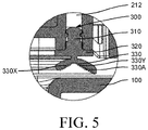
- FIG. 5 is a schematic partial diagram of a drawer assembly in an unsealed state according to an embodiment of the present utility model.
- the sealing surface 330 may include a first sealing surface 330X and a second sealing surface 330Y that are intersected.
- the first sealing surface 330X and the second sealing surface 330Y are flattened to achieve a better sealing effect between the sealing member 300 and the drawer 100.
- the cross section of the sealing member 300 may be in a shape of a Chinese character " " ".
- the upper part 310 of the cross section “ “” is formed as a fixing portion of the sealing member 300, and is adapted to be inserted into the second slot 212 to be tightly mounted on the cap frame 210.
- the width of the traverse part 320 on the cross section “ “ of the sealing member 300 is greater than that of the upper part 310.
- the traverse part 320 of the cross section " " is tightly attached to the bottom of the cap frame 210 and defines the depth of insertion of the upper part 310 in the second slot 212.
- the bottom of the lower part of the cross section " " is adapted to be used as the sealing surface 330 of the sealing member 300.
- FIG. 6 is a schematic partial diagram of a drawer assembly in a sealed state according to an embodiment of the present utility model.
- the sealing member 300 especially the lower part of the sealing surface 330 of the sealing member 300 is elastic and compressible to deform. Therefore, when the cap 200 closes the opening 110, the sealing member 300 may be extruded by the cap 200 and the drawer 100 to expel at least part of air between the sealing surface 330 and the drawer 100 and suck in the drawer 100 through the sealing surface 330 to seal the drawer assembly 10.
- the lower part of the sealing member 300 presses against the upper edge of the drawer 100 through the sealing surface 330, and is extruded to deform, at the same time, at least part of air between the sealing surface 330 and the upper edge of the drawer 100 is expelled, so that the sealing surface 330 can suck in the upper edge of the drawer 100 and seal the drawer assembly 10.
- the sealing member 300 may be provided with an air exhaust hole with two runthrough ends. One end of the air exhaust hole communicates with external air, and the other end communicates with the sealing surface 330 of the sealing member 300.
- the air exhaust hole is adapted to timely expel the at least part of air between the sealing surface 330 and the drawer 100 when the cap 200 closes the opening 110.
- the sealing surface 330 of the sealing member 300 is provided with a rough feature 330A. Therefore, when the cap 200 closes the opening 110, a contact area between the sealing surface 330 of the sealing member 300 and the drawer 100 is relatively reduced; and the cap 200 can be easily pushed away by merely applying relatively little thrust when the opening 110 of the drawer 100 needs to be opened.
- the rough feature 330A is disposed on the sealing surface of the sealing member 300 facing toward the cap 200.
- the cap 200 closes the opening 110, a contact area between the sealing surface of the sealing member 300 and the cap 200 is relatively reduced; and similarly the cap 200 can be easily pushed away by merely applying relatively little thrust when the opening 110 of the drawer 100 needs to be opened.
- the technical solutions provided in the embodiments of the present utility model can make a user open the opening 110 of the drawer 100 more easily, greatly facilitating use by the user and improving use experience of the user.
- the sealing surface 330 of the sealing member 300 may be provided with the rough feature 330A along a whole circle of a surface of the sealing surface 330 that is in sealing contact with the drawer 100 or the cap 200.
- FIG. 7 is a schematic diagram of a sealing member according to an embodiment of the present utility model.
- the sealing surface 330 of the sealing member 300 may be provided with the rough feature 330A in a front region 331 and/or a rear region 332 of the sealing surface 330, especially provided with the rough feature 330A in both the front region 331 and the rear region 332.
- That the sealing member 300 is mounted on the cap 200 is used as an example for description. As compared with other regions of the sealing surface 330, when the cap 200 needs to slide backward relative to the drawer 100 to open the opening 110, larger thrust needs to be applied to the front region 331 and the rear region 332 of the sealing surface 330.
- the front region 331 and the rear region 332 of the sealing surface 330 being provided with the rough feature 330A can help reduce the foregoing thrust.
- the cap 200 can be easily pushed away to open the opening 110 of the drawer 100.
- the rough feature 330A may include a leather feature, a grain feature, a convex-concave feature, or the like.
- the grain feature may be a milled sand feature.
- the surface roughness of the sealing surface 330 that is provided with the rough feature 330A should not be excessively large, to avoid a case that the sealing surface 330 cannot effectively suck in the drawer 100 and cannot effectively seal the drawer assembly 10 when the cap 200 closes the opening 110.
- the specific surface roughness of the sealing surface 330 may be specifically determined according to attributes of the sealing surface 330 and the drawer 100, user experience about thrust required to open the drawer 100, and the like.
- the sealing member 300 may be mounted to one of the cap 200 and the drawer 100.
- a gap may exist, in a gravity direction, between the sealing member 300 and the other one of the cap 200 and the drawer 100.
- the existence of the gap not only helps the cap 200 slide relative to the drawer 100 to successfully open the opening 110, but also prevents the rough feature of the sealing surface 330 from being reduced or worn.
- FIG. 8 is another cross-sectional view of a drawer assembly along a front-rear direction thereof according to an embodiment of the present utility model.
- the sealing member 300 is mounted on one side of the cap 200 facing toward the drawer 100.
- a gap g1 exists, in a gravity direction, between the sealing member 300 and the drawer 100.
- the existence of the gap g1 can reduce and even avoid sliding contact between the sealing surface 330 of the sealing member 300 and the drawer 100, to avoid sliding friction between the sealing surface 330 of the sealing member 300 and the drawer 100.
- the method not only helps the cap 200 slide relative to the drawer 100 to successfully open the opening 110, but also prevents the rough feature of the sealing surface 330 from being reduced or worn.
- the drawer 100 may further include a supporting portion 120 adapted to support the cap 200.
- the gap g1 may exist, in a gravity direction, between the sealing member 300 and the supporting portion 120; and when then cap 200 closes the opening, the sealing member 300 is pressed onto the supporting portion 120.
- the drawer assembly 10 may further include rollers.
- the rollers may be disposed on one of the cap 200 and the drawer 100.
- the other one of the cap 200 and the drawer 100 has a recess.
- the roller When the cap 200 closes the opening 110, the roller enters the recess to eliminate the gap g1, and when the cap 200 slides relative to the drawer 100 to open the opening 110, the roller slides out from the recess to form the gap g1.
- Each group includes two rollers, one being a front roller 410 disposed near the front part of the drawer 100, the other being a rear roller 420 disposed near the rear part of the drawer 100.
- the front roller 410 may be mounted on the cap 200, and the rear roller 420 may be mounted on the drawer 100, as shown in FIG. 2 .
- FIG. 9 is a cross-sectional view of a drawer assembly along a left-right direction thereof according to an embodiment of the present utility model.
- a manner of mounting the front roller 410 on the cap 200 is described in the following with reference to FIG. 9 .
- a mounting portion 213 that extends along a horizontal direction to the left side of the cap frame 210 is disposed on the lower left side of the cap frame 210.
- the mounting portion 213 is provided with a third slot 214 that faces toward the outside of the cap frame 210 and is isolated from the second slot 212.
- a roller rotating shaft 430 is mounted in the third slot 214.
- One end of the roller rotating shaft 430 may be secured to the third slot 214 through a threaded connection, and the other end is in rotating connection to the rotating center of the front roller 410.
- the gap g2 can not only ensure that rolling of the front roller 410 is not affected by the sealing member 300, but also avoid abrasion of the sealing member 300 caused by rolling of the front roller 410.
- FIG. 9 merely shows an implementation of the front roller 410 mounted on the left side of the cap 200.
- the implementation thereof is similar to FIG. 9 , and is not repeated.
- a front recess 121 that faces toward the front roller 410 may be disposed on the supporting portion 120 of the drawer 100, as shown in FIG. 2 .
- the front roller 410 entering the front recess 121 to eliminate the gap g1
- the front roller 410 slides out from the front recess 121 to form the gap g1.
- the front roller 410 may slide backward relative to the drawer 100 on the supporting portion 120.
- the speed of rolling back by the front roller 410 is the same as the speed at which the cap 200 slides backward.
- the lowest point D1 of the front roller 410 can be lower than the lowest point D2 of the sealing member 300 in a free state, to ensure that there is a gap g1 between the sealing member 300 and the upper edge of the drawer 100 when the cap 200 moves relative to the drawer 100 with the support of the front roller 410.
- the free state is a state in which the sealing member 300 is not extruded by the cap 200 because of the gravity of the cap 200.
- a top wall of the drawer 100 along a direction of movement of the front roller 410 is provided with a limiting portion 130, as shown in FIG. 2 .
- the limiting portion 130 is adapted to restrict movement of the front roller 410 in an axial direction of the limiting portion, to prevent the front roller 410 from sliding beyond the supporting portion 120 in a rolling process.
- the rear roller 420 may also be mounted on the left and right sides of the drawer 100 through a roller rotating shaft.
- the mounting principle of the rear roller 420 is the same as the mounting principle of the front roller 410.
- the cap frame 210 is further provided with an adaption 215.
- the adaption 215 is provided with a rear recess 216 open toward the corresponding rear roller 420, as shown in FIG. 3 .
- the rear roller 420 When the cap 200 closes the opening 110, the rear roller 420 enters the rear recess 216 to eliminate the gap g1, and when the cap 200 slides relative to the drawer 100 to open the opening 110, the rear roller 420 slides out from the rear recess 216 to form the gap g1.
- the embodiments of the present utility model further provide a refrigerator, including a storage compartment and the foregoing drawer assembly 10; the drawer assembly 10 being disposed in the storage compartment, and being capable of being pulled out relative to the storage compartment.
- drawer assembly 10 provided in the embodiments of the present utility model may further be applied to other refrigerating devices that need to store items in an isolated and sealing manner such as a refrigerated cabinet and a freezer.
Landscapes
- Engineering & Computer Science (AREA)
- Chemical & Material Sciences (AREA)
- Combustion & Propulsion (AREA)
- Physics & Mathematics (AREA)
- Mechanical Engineering (AREA)
- Thermal Sciences (AREA)
- General Engineering & Computer Science (AREA)
- Drawers Of Furniture (AREA)
- Refrigerator Housings (AREA)
- Closures For Containers (AREA)
Abstract
Description
- The present utility model relates to the field of household appliance technologies, and in particular, to a drawer assembly and a refrigerator.
- With continuous improvement of people's living standard and diversified development of food storage requirements, functional requirements of a user for a refrigerator gradually increase. When there are various types of food stored in a refrigerator, flavor tainting easily takes place in the various types of food, consequently affecting use experience of a user. In order to prevent mutual tainting of flavors among the various types of food/items stored in the refrigerator, one way is to dispose sealed drawers in the refrigerator.
- The objective of the present utility model is to provide an improved drawer assembly and refrigerator.
- The drawer assembly provided in the embodiments of the present utility model includes a drawer, a cap, and a sealing member; the drawer having an upward opening; the cap being capable of sliding forward and backward relative to the drawer to open or close the opening; and the sealing member being disposed between the cap and the drawer, and having a sealing surface that seals the drawer or the cap, and the sealing surface is provided with a rough feature.
- Optionally, the sealing surface is provided with the rough feature on an entire surface of the sealing surface that is in sealing contact with the drawer or the cap.
- Optionally, the sealing surface is provided with the rough feature in a front region and/or a rear region of the sealing surface that is in sealing contact with the drawer or the cap.
- Optionally, the rough feature includes a leather feature, a grain feature, or a convex-concave feature.
- Optionally, when the cap closes the opening, the sealing member is extruded by the cap and the drawer to expel at least part of air between the sealing member and the drawer or the cap and suck in the drawer or the cap to seal the drawer assembly.
- Optionally, the sealing member is mounted to one of the cap and the drawer, and when the cap slides relative to the drawer, a gap exists, in a gravity direction, between the sealing member and the other one of the cap and the drawer.
- Optionally, the sealing member is mounted on the cap, and the drawer includes a supporting portion adapted to support the cap; and when the cap closes the opening, the sealing member is pressed on the supporting portion.
- Optionally, the drawer assembly further includes a roller, the roller being disposed in one of the cap and the drawer, the other one of the cap and the drawer having a recess, when the cap closes the opening, the roller entering the recess to eliminate the gap, and when the cap slides relative to the drawer to open the opening, the roller sliding out from the recess to form the gap.
- Optionally, a top wall of the drawer along a direction of movement of the roller is provided with a limiting portion, and the limiting portion is adapted to restrict movement of the roller in an axial direction of the limiting portion.
- The embodiments of the present utility model further provide a refrigerator, including a storage compartment and the foregoing drawer assembly; the drawer assembly being disposed in the storage compartment, and being capable of being pulled out relative to the storage compartment.
- Compared with the prior art, the technical solutions of the embodiments of the present utility model have beneficial effects. For example, because the sealing surface of the sealing member is provided with the rough feature, when the cap closes the opening, a contact area between the sealing member and the drawer or the cap is relatively reduced; and the opening of the drawer can be opened by merely applying relatively little thrust to the cap, greatly improving use experience of a user.
- In another example, in an implementation in which the sealing surface is extruded to deform to form a negative pressure between the sealing surface and the drawer or the cap to improve the sealing effect, because the sealing surface is provided with the rough feature, when an external force is applied to the cap, the negative pressure is easily eliminated, further helping the cap slide relative to the drawer to open the opening.
-
-
FIG. 1 is a schematic diagram of a drawer assembly according to an embodiment of the present utility model; -
FIG. 2 is an exploded diagram of a drawer assembly according to an embodiment of the present utility model; -
FIG. 3 is a schematic diagram of a cap according to an embodiment of the present utility model; -
FIG. 4 is a cross-sectional view of a drawer assembly along a front-rear direction thereof according to an embodiment of the present utility model; -
FIG. 5 is a schematic partial diagram of a drawer assembly in an unsealed state according to an embodiment of the present utility model; -
FIG. 6 is a schematic partial diagram of a drawer assembly in a sealed state according to an embodiment of the present utility model; -
FIG. 7 is a schematic diagram of a sealing member according to an embodiment of the present utility model; -
FIG. 8 is another cross-sectional view of a drawer assembly along a front-rear direction thereof according to an embodiment of the present utility model; and -
FIG. 9 is a cross-sectional view of a drawer assembly along a left-right direction thereof according to an embodiment of the present utility model. - As described in the background, usually, a sealing member is disposed between a drawer body and a drawer cover in the existing sealed drawer to achieve the sealing effect. A sealing surface of the existing sealing member is usually relatively smooth.
- To resolve the foregoing technical problem, the embodiments of the present utility model provide a drawer assembly, including a drawer, a cap, and a sealing member; the drawer having an upward opening, the cap being capable of sliding forward and backward relative to the drawer to open or close the opening, and the sealing member being disposed between the cap and the drawer, and having a sealing surface that seals the drawer or the cap, and the sealing surface is provided with a rough feature.
- Compared with the prior art in which the sealing surface of the sealing member is relatively smooth, the sealing surface of the sealing member provided in the embodiments of the present utility model is provided with the rough feature. Therefore, when the cap closes the opening, a contact area between the sealing member and the drawer or the cap is relatively reduced; and the cap can be easily pushed away by merely applying relatively little thrust to open the opening when the opening of the drawer needs to be opened, greatly facilitating use by a user and improving use experience of the user.
- To make the objectives, features, and beneficial effects of the embodiments of the present utility model more comprehensible, the following describes the specific embodiments of the present utility model in detail with reference to the accompanying drawings.
- In order to facilitate description of the drawer assembly provided in the embodiments of the present utility model, some of the accompanying draws provided in the embodiments of the present utility model show six directions that are up, down, left, right, front, and rear. The six directions are determined from a perspective of the drawer assembly facing a user in a normal use state. The "front" represents a direction in which the drawer assembly draws near the user, the "rear" represents a direction in which drawer assembly is away from the user, "left" and "right" are determined according to a natural orientation division based on the foregoing "front" and "rear" directions, the "up" represents a direction in which the cap of the drawer assembly is located, and "down" represents a direction in which the drawer of the drawer assembly is located. Referring to the foregoing directions, in technical solutions provided in the embodiments of the present utility model, the cap slides backward relative to the drawer to open the opening, and the cap slides forward relative to the drawer to close the opening. It should be understood that, from another perspective of the drawer assembly, there are also corresponding directions up, down, left, right, front, and rear corresponding to the perspective. The directions up, down, left, right, front, and rear shown in some of the accompanying drawings provided in the embodiments of the present utility model are merely used for helping describe the technical solutions provided in the embodiments of the present utility model, but do not limit description of the solutions.
-
FIG. 1 is a schematic diagram of a drawer assembly according to an embodiment of the present utility model; andFIG. 2 is an exploded diagram of a drawer assembly according to an embodiment of the present utility model. - As shown in
FIG. 1 andFIG. 2 , adrawer assembly 10, including adrawer 100, acap 200, and asealing member 300 is provided in the embodiments of the present utility model. Thedrawer 100 has anupward opening 110; thecap 200 is capable of sliding forward and backward relative to thedrawer 100 to open or close theopening 110; and the sealingmember 300 is disposed between thecap 200 and thedrawer 100, and has asealing surface 330 that seals thedrawer 100 or thecap 200. The sealingsurface 330 is provided with a rough feature. -
FIG. 3 is a schematic diagram of a cap according to an embodiment of the present utility model. - As shown in
FIG. 3 , in an embodiment, thecap 200 may include acap frame 210 and acap lid 220 disposed in thecap frame 210. - The
cap frame 210 may be made of a material such as plastic, silica gel, or the like. Thecap lid 220 may be made of a tempered glass panel. The tempered glass panel may, on one hand, strengthen a gravity of thecap 200 applied to the sealingmember 300 to extrude the sealingmember 300 to seal thedrawer assembly 10, and on the other hand, make it possible that a user can observe the inside of thedrawer 100 through thecap lid 220 because of the transparency of the tempered glass panel. - In some other embodiments, the
cap lid 220 may alternatively be made of other materials with sufficient weight. For example, the material may be a ceramic plate, a ceramic plate embedded with tempered glass, or the like. - In the technical solutions provided in the embodiments of the present utility model, the sealing
member 300 may be mounted to one of thecap 200 and thedrawer 100. - In a preferred embodiment, the sealing
member 300 may be mounted on one side of thecap 200 facing toward thedrawer 100. When thecap 200 closes theopening 110, the sealingmember 300 can be pressed along with thecap 200 onto thedrawer 100 and be extruded to seal thedrawer assembly 10. Compared with a case that the sealingmember 300 is mounted on thedrawer 100, mounting the sealingmember 300 on thecap 200 is more advantageous to the hiding of the sealingmember 300, to effectively reduce the possibility that the sealingmember 300 is contaminated. -
FIG. 4 is a cross-sectional view of a drawer assembly along a front-rear direction thereof according to an embodiment of the present utility model. - As shown in
FIG. 4 , in an embodiment, thecap frame 210 may be provided with afirst slot 211 and asecond slot 212 that are isolated from each other. - The
first slot 211 may be disposed inside of thecap frame 210 and open towards thecap lid 220 to be adapted to receive thecap lid 220. Thecap lid 220 may be inserted into thefirst slot 211 through an edge of thecap lid 220 to be mounted in thecap frame 210. - The
second slot 212 may be disposed at the bottom of thecap frame 210 and open towards the sealingmember 300 to be adapted to receive thesealing member 300. The sealingmember 300 may be inserted into thesecond slot 212 through the top of the sealingmember 300 to be mounted on one side of thecap frame 210 facing toward thedrawer 100. - In a preferred embodiment, the
second slot 212 may be located on the outside of thefirst slot 211 to ensure that there is no mutual effect between thefirst slot 211 and thesecond slot 212. The outside is a side of thecap frame 210 that is away from thecap lid 220 in a horizontal direction. - In a preferred embodiment, the
first slot 211 may be disposed along the whole inside circle of thecap frame 210 to be adapted to a case that thecap lid 220 is tightly mounted. The inside is a side of thecap frame 210 that is near thecap lid 220 in a horizontal direction. - In a preferred embodiment, the sealing
member 300 may be a closed sealing ring, and thesecond slot 212 may be disposed along the whole bottom circle of thecap frame 210 to be adapted to a case that the sealing ring is tightly mounted. -
FIG. 5 is a schematic partial diagram of a drawer assembly in an unsealed state according to an embodiment of the present utility model. - As shown in
FIG. 5 , in a preferred embodiment, the sealingsurface 330 may include afirst sealing surface 330X and asecond sealing surface 330Y that are intersected. When the sealingmember 300 is extruded, thefirst sealing surface 330X and thesecond sealing surface 330Y are flattened to achieve a better sealing effect between the sealingmember 300 and thedrawer 100. - The cross section of the sealing
member 300 may be in a shape of a Chinese character "". The
upper part 310 of the cross section "" is formed as a fixing portion of the sealing
member 300, and is adapted to be inserted into thesecond slot 212 to be tightly mounted on thecap frame 210. The width of thetraverse part 320 on the cross section "" of the sealing
member 300 is greater than that of theupper part 310. Thetraverse part 320 of the cross section "" is tightly attached to the bottom of the
cap frame 210 and defines the depth of insertion of theupper part 310 in thesecond slot 212. The bottom of the lower part of the cross section "" is adapted to be used as the sealing
surface 330 of the sealingmember 300. -
FIG. 6 is a schematic partial diagram of a drawer assembly in a sealed state according to an embodiment of the present utility model. - As shown in
FIG. 6 , the sealingmember 300, especially the lower part of the sealingsurface 330 of the sealingmember 300 is elastic and compressible to deform. Therefore, when thecap 200 closes theopening 110, the sealingmember 300 may be extruded by thecap 200 and thedrawer 100 to expel at least part of air between the sealingsurface 330 and thedrawer 100 and suck in thedrawer 100 through the sealingsurface 330 to seal thedrawer assembly 10. - Specifically, when the
cap 200 closes theopening 110, the lower part of the sealingmember 300 presses against the upper edge of thedrawer 100 through the sealingsurface 330, and is extruded to deform, at the same time, at least part of air between the sealingsurface 330 and the upper edge of thedrawer 100 is expelled, so that the sealingsurface 330 can suck in the upper edge of thedrawer 100 and seal thedrawer assembly 10. - Further, the sealing
member 300 may be provided with an air exhaust hole with two runthrough ends. One end of the air exhaust hole communicates with external air, and the other end communicates with the sealingsurface 330 of the sealingmember 300. The air exhaust hole is adapted to timely expel the at least part of air between the sealingsurface 330 and thedrawer 100 when thecap 200 closes theopening 110. - Further referring to
FIG. 5 , in the technical solutions provided in the embodiments of the present utility model, the sealingsurface 330 of the sealingmember 300 is provided with arough feature 330A. Therefore, when thecap 200 closes theopening 110, a contact area between the sealingsurface 330 of the sealingmember 300 and thedrawer 100 is relatively reduced; and thecap 200 can be easily pushed away by merely applying relatively little thrust when theopening 110 of thedrawer 100 needs to be opened. - In addition, when the sealing
member 300 is mounted on thedrawer 100, therough feature 330A is disposed on the sealing surface of the sealingmember 300 facing toward thecap 200. When thecap 200 closes theopening 110, a contact area between the sealing surface of the sealingmember 300 and thecap 200 is relatively reduced; and similarly thecap 200 can be easily pushed away by merely applying relatively little thrust when theopening 110 of thedrawer 100 needs to be opened. - Compared with a case in the prior art that a sealing surface of a sealing member is relatively smooth, suction between the sealing surface and a drawer or a cap is relatively large, and it is difficult to open the drawer, the technical solutions provided in the embodiments of the present utility model can make a user open the
opening 110 of thedrawer 100 more easily, greatly facilitating use by the user and improving use experience of the user. - In an embodiment, the sealing
surface 330 of the sealingmember 300 may be provided with therough feature 330A along a whole circle of a surface of the sealingsurface 330 that is in sealing contact with thedrawer 100 or thecap 200. -
FIG. 7 is a schematic diagram of a sealing member according to an embodiment of the present utility model. - As shown in
FIG. 7 , in some other embodiments, the sealingsurface 330 of the sealingmember 300 may be provided with therough feature 330A in afront region 331 and/or arear region 332 of the sealingsurface 330, especially provided with therough feature 330A in both thefront region 331 and therear region 332. - That the sealing
member 300 is mounted on thecap 200 is used as an example for description. As compared with other regions of the sealingsurface 330, when thecap 200 needs to slide backward relative to thedrawer 100 to open theopening 110, larger thrust needs to be applied to thefront region 331 and therear region 332 of the sealingsurface 330. - Therefore, the
front region 331 and therear region 332 of the sealingsurface 330 being provided with therough feature 330A can help reduce the foregoing thrust. - In addition, as compared with a case that the whole circle of the sealing
surface 330 is provided with therough feature 330A, in the technical solution provided in the foregoing embodiment, by merely disposing a smaller quantity ofrough features 330A on a partial region of the sealingsurface 330, thecap 200 can be easily pushed away to open theopening 110 of thedrawer 100. - In the technical solutions provided in the embodiments of the present utility model, the
rough feature 330A may include a leather feature, a grain feature, a convex-concave feature, or the like. The grain feature may be a milled sand feature. - It should be noted that, the surface roughness of the sealing
surface 330 that is provided with therough feature 330A should not be excessively large, to avoid a case that the sealingsurface 330 cannot effectively suck in thedrawer 100 and cannot effectively seal thedrawer assembly 10 when thecap 200 closes theopening 110. - The specific surface roughness of the sealing
surface 330 may be specifically determined according to attributes of the sealingsurface 330 and thedrawer 100, user experience about thrust required to open thedrawer 100, and the like. - In addition, as compared with the case that the sealing
member 300 is mounted on thedrawer 100, specific surface roughness of a corresponding sealing surface needs to be specifically determined according to attributes of the sealingsurface 330 and thecap 200, user experience about thrust required to open thedrawer 200, and the like. - The specific method for determining the surface roughness and the method for setting different levels of surface roughness on the sealing
surface 330 of the sealingmember 300 according to requirements are both common technologies in this technical field, which, therefore, are not repeated in the technical solutions provided in the embodiments of the present utility model. - Further, in the technical solutions provided in the embodiments of the present utility model, the sealing
member 300 may be mounted to one of thecap 200 and thedrawer 100. When thecap 200 slides relative to thedrawer 100, a gap may exist, in a gravity direction, between the sealingmember 300 and the other one of thecap 200 and thedrawer 100. - The existence of the gap not only helps the
cap 200 slide relative to thedrawer 100 to successfully open theopening 110, but also prevents the rough feature of the sealingsurface 330 from being reduced or worn. -
FIG. 8 is another cross-sectional view of a drawer assembly along a front-rear direction thereof according to an embodiment of the present utility model. - As shown in
FIG. 8 , in an embodiment, the sealingmember 300 is mounted on one side of thecap 200 facing toward thedrawer 100. When thecap 200 slides relative to thedrawer 100 to open theopening 110, a gap g1 exists, in a gravity direction, between the sealingmember 300 and thedrawer 100. - The existence of the gap g1 can reduce and even avoid sliding contact between the sealing
surface 330 of the sealingmember 300 and thedrawer 100, to avoid sliding friction between the sealingsurface 330 of the sealingmember 300 and thedrawer 100. The method not only helps thecap 200 slide relative to thedrawer 100 to successfully open theopening 110, but also prevents the rough feature of the sealingsurface 330 from being reduced or worn. - Further referring to
FIG. 2 andFIG. 8 , thedrawer 100 may further include a supportingportion 120 adapted to support thecap 200. When thecap 200 slides relative to thedrawer 100, the gap g1 may exist, in a gravity direction, between the sealingmember 300 and the supportingportion 120; and when then cap 200 closes the opening, the sealingmember 300 is pressed onto the supportingportion 120. - Further, in the technical solutions provided in the embodiments of the present utility model, the
drawer assembly 10 may further include rollers. The rollers may be disposed on one of thecap 200 and thedrawer 100. The other one of thecap 200 and thedrawer 100 has a recess. - When the
cap 200 closes theopening 110, the roller enters the recess to eliminate the gap g1, and when thecap 200 slides relative to thedrawer 100 to open theopening 110, the roller slides out from the recess to form the gap g1. - Referring to
FIG. 1 andFIG. 2 . There may be two groups of rollers. One group is disposed on the left side of thedrawer 100, and the other group is disposed on the right side of thedrawer 100. Each group includes two rollers, one being afront roller 410 disposed near the front part of thedrawer 100, the other being arear roller 420 disposed near the rear part of thedrawer 100. - In an embodiment, the
front roller 410 may be mounted on thecap 200, and therear roller 420 may be mounted on thedrawer 100, as shown inFIG. 2 . -
FIG. 9 is a cross-sectional view of a drawer assembly along a left-right direction thereof according to an embodiment of the present utility model. - A manner of mounting the
front roller 410 on thecap 200 is described in the following with reference toFIG. 9 . As shown inFIG. 9 , a mountingportion 213 that extends along a horizontal direction to the left side of thecap frame 210 is disposed on the lower left side of thecap frame 210. The mountingportion 213 is provided with athird slot 214 that faces toward the outside of thecap frame 210 and is isolated from thesecond slot 212. Aroller rotating shaft 430 is mounted in thethird slot 214. One end of theroller rotating shaft 430 may be secured to thethird slot 214 through a threaded connection, and the other end is in rotating connection to the rotating center of thefront roller 410. - Further referring to
FIG. 9 , there is a gap g2 in an axial direction of thefront roller 410 between thefront roller 410 and the sealingmember 300. The gap g2 can not only ensure that rolling of thefront roller 410 is not affected by the sealingmember 300, but also avoid abrasion of the sealingmember 300 caused by rolling of thefront roller 410. -
FIG. 9 merely shows an implementation of thefront roller 410 mounted on the left side of thecap 200. For thefront roller 410 mounted on the right side of thecap 200, the implementation thereof is similar toFIG. 9 , and is not repeated. - Further, corresponding to a position of the
front roller 410, afront recess 121 that faces toward thefront roller 410 may be disposed on the supportingportion 120 of thedrawer 100, as shown inFIG. 2 . When thecap 200 closes theopening 110, thefront roller 410 entering thefront recess 121 to eliminate the gap g1, and when thecap 200 slides relative to thedrawer 100 to open theopening 110, thefront roller 410 slides out from thefront recess 121 to form the gap g1. - After the
front roller 410 slides out from thefront recess 121, thefront roller 410 may slide backward relative to thedrawer 100 on the supportingportion 120. The speed of rolling back by thefront roller 410 is the same as the speed at which thecap 200 slides backward. - Further referring to
FIG. 8 and FIG. 9 , in the technical solutions provided in the embodiments of the present utility model, the lowest point D1 of thefront roller 410 can be lower than the lowest point D2 of the sealingmember 300 in a free state, to ensure that there is a gap g1 between the sealingmember 300 and the upper edge of thedrawer 100 when thecap 200 moves relative to thedrawer 100 with the support of thefront roller 410. The free state is a state in which the sealingmember 300 is not extruded by thecap 200 because of the gravity of thecap 200. - Further, a top wall of the
drawer 100 along a direction of movement of thefront roller 410 is provided with a limitingportion 130, as shown inFIG. 2 . The limitingportion 130 is adapted to restrict movement of thefront roller 410 in an axial direction of the limiting portion, to prevent thefront roller 410 from sliding beyond the supportingportion 120 in a rolling process. - In the technical solutions provided in the embodiments of the present utility model, the
rear roller 420 may also be mounted on the left and right sides of thedrawer 100 through a roller rotating shaft. The mounting principle of therear roller 420 is the same as the mounting principle of thefront roller 410. - Correspondingly, as shown in
FIG. 2 andFIG. 3 , corresponding to a position of therear roller 420, thecap frame 210 is further provided with anadaption 215. Theadaption 215 is provided with arear recess 216 open toward the correspondingrear roller 420, as shown inFIG. 3 . - When the
cap 200 closes theopening 110, therear roller 420 enters therear recess 216 to eliminate the gap g1, and when thecap 200 slides relative to thedrawer 100 to open theopening 110, therear roller 420 slides out from therear recess 216 to form the gap g1. - The embodiments of the present utility model further provide a refrigerator, including a storage compartment and the foregoing
drawer assembly 10; thedrawer assembly 10 being disposed in the storage compartment, and being capable of being pulled out relative to the storage compartment. - It should be noted that, the
drawer assembly 10 provided in the embodiments of the present utility model may further be applied to other refrigerating devices that need to store items in an isolated and sealing manner such as a refrigerated cabinet and a freezer. - Although specific implementations have been described above, the implementations are not intended to limit the scope of the present invention, even if only one implementation is described with respect to specific features. The feature examples provided in the present invention are intended to be illustrative rather than limiting, unless otherwise stated. In a specific implementation, technical features of one or more dependent claim and technical features of independent claims are combined according to actual requirements and in a feasible technology. Technical features from corresponding independent claims may be combined by any proper manner rather than only by a specific combination exemplified in the claims.
- Although the present utility model is disclosed above, the present utility model is not limited thereto. Any person skilled in the art may make variations and modifications without departing from the spirit and scope of the present utility model. Therefore, the protection scope of the present utility model should be subject to the claims.
Claims (10)
- A drawer assembly (10), comprising a drawer (100), a cap (200), and a sealing member (300); the drawer (100) having an upward opening (110); the cap (200) being capable of sliding forward and backward relative to the drawer (100) to open or close the opening (110); and the sealing member (300) being disposed between the cap (200) and the drawer (100), and having a sealing surface (330) that seals the drawer (100) or the cap (200), characterized in that, the sealing surface (330) is provided with a rough feature (330A).
- The drawer assembly (10) according to claim 1, characterized in that, the sealing surface (330) is provided with the rough feature (330A) on an entire surface of the sealing surface that is in sealing contact with the drawer (100) or the cap (200).
- The drawer assembly (10) according to claim 1, characterized in that, the sealing surface (330) is provided with the rough feature (330A) in a front region (331) and/or a rear region (332) of the sealing surface that is in sealing contact with the drawer (100) or the cap (200).
- The drawer assembly (10) according to any one of claims 1 to 3, characterized in that, the rough feature (330A) comprises a leather feature, a grain feature, or a convex-concave feature.
- The drawer assembly (10) according to claim 1, characterized in that, when the cap (200) closes the opening (110), the sealing member (300) is extruded by the cap (200) and the drawer (100) to expel at least part of air between the sealing member and the drawer (100) or the cap (200) and suck in the drawer (100) or the cap (200) to seal the drawer assembly (10).
- The drawer assembly (10) according to claim 1, characterized in that, the sealing member (300) is mounted to one of the cap (200) and the drawer (100), and when the cap (200) slides relative to the drawer (100), a gap (g1) exists, in a gravity direction, between the sealing member (300) and the other one of the cap (200) and the drawer (100).
- The drawer assembly (10) according to claim 6, characterized in that, the sealing member (300) is mounted on the cap (200), and the drawer (100) comprises a supporting portion (120) adapted to support the cap (200); and when the cap (200) closes the opening (110), the sealing member (300) is pressed on the supporting portion (120).
- The drawer assembly (10) according to claim 6 or 7, characterized by further comprising a roller (410, 420), the roller (410, 420) being disposed in one of the cap (200) and the drawer (100), the other one of the cap (200) and the drawer (100) having a recess (121, 216), when the cap (200) closes the opening (110), the roller (410, 420) entering the recess (121, 216) to eliminate the gap (g1), and when the cap (200) slides relative to the drawer (100) to open the opening (110), the roller (410, 420) sliding out from the recess (121, 216) to form the gap (g1).
- The drawer assembly (10) according to claim 8, characterized in that, a top wall of the drawer (100) along a direction of movement of the roller is provided with a limiting portion (130), and the limiting portion is adapted to restrict movement of the roller in an axial direction of the limiting portion.
- A refrigerator, comprising a storage compartment, characterized by further comprising the drawer assembly (10) according to any one of claims 1 to 9; and the drawer assembly (10) being disposed in the storage compartment, and being capable of being pulled out relative to the storage compartment.
Applications Claiming Priority (1)
| Application Number | Priority Date | Filing Date | Title |
|---|---|---|---|
| CN201922251812.4U CN211876510U (en) | 2019-12-16 | 2019-12-16 | Drawer assembly and refrigerator |
Publications (1)
| Publication Number | Publication Date |
|---|---|
| EP3839391A1 true EP3839391A1 (en) | 2021-06-23 |
Family
ID=73243299
Family Applications (1)
| Application Number | Title | Priority Date | Filing Date |
|---|---|---|---|
| EP20211426.0A Withdrawn EP3839391A1 (en) | 2019-12-16 | 2020-12-03 | Drawer assembly and refrigerator |
Country Status (3)
| Country | Link |
|---|---|
| US (1) | US11499772B2 (en) |
| EP (1) | EP3839391A1 (en) |
| CN (1) | CN211876510U (en) |
Families Citing this family (1)
| Publication number | Priority date | Publication date | Assignee | Title |
|---|---|---|---|---|
| CN116428808A (en) * | 2022-01-04 | 2023-07-14 | 青岛海尔电冰箱有限公司 | A refrigerator and its drawer assembly |
Citations (6)
| Publication number | Priority date | Publication date | Assignee | Title |
|---|---|---|---|---|
| JP2002282192A (en) * | 2001-03-28 | 2002-10-02 | Sanyo Electric Co Ltd | Dishwasher |
| GB2398355A (en) * | 2003-09-05 | 2004-08-18 | Applied Design & Eng Ltd | A magnetic strip seal for a cold storage appliance |
| US20130270986A1 (en) * | 2012-04-16 | 2013-10-17 | Lg Electronics Inc. | Refrigerator having vegetable storage container |
| US20140077679A1 (en) * | 2012-09-18 | 2014-03-20 | Lg Electronics Inc. | Refrigerator with drawer sealing apparatus |
| CN207936610U (en) * | 2017-11-30 | 2018-10-02 | 青岛海尔股份有限公司 | Refrigerator and its drawer appliance |
| WO2019105473A1 (en) * | 2017-11-30 | 2019-06-06 | 青岛海尔股份有限公司 | Refrigerator and drawer assembly thereof |
Family Cites Families (14)
| Publication number | Priority date | Publication date | Assignee | Title |
|---|---|---|---|---|
| US3126589A (en) * | 1964-03-31 | Monti | ||
| US2188815A (en) * | 1937-07-31 | 1940-01-30 | Corduroy Rubber Company | Gasket |
| US2379193A (en) * | 1941-06-03 | 1945-06-26 | Westinghouse Electric Corp | Refrigeration apparatus |
| US2345273A (en) * | 1942-02-20 | 1944-03-28 | Louis A Macklanburg | Weather strip |
| US3323256A (en) * | 1965-04-02 | 1967-06-06 | H O Canfield Co Inc | Sealing gasket of combined rigid and flexible extrusions |
| DE9103247U1 (en) * | 1991-03-16 | 1991-06-13 | Wilhelm Fette Gmbh, 2053 Schwarzenbek | Sealing strip for the housing of a tablet press |
| JP4009944B2 (en) * | 2002-09-17 | 2007-11-21 | トキワケミカル工業株式会社 | Gasket for refrigerator |
| CN102454789B (en) * | 2010-10-21 | 2016-09-14 | 博西华家用电器有限公司 | Sealing member, vacuum chamber and refrigerating plant |
| KR102028022B1 (en) * | 2013-04-05 | 2019-10-04 | 삼성전자주식회사 | Refrigerator |
| WO2015050512A1 (en) * | 2013-10-03 | 2015-04-09 | Arcelik Anonim Sirketi (A.S.) | A refrigerator comprising a crisper |
| KR102236740B1 (en) * | 2014-08-07 | 2021-04-06 | 삼성전자주식회사 | Refrigerator |
| KR101639135B1 (en) * | 2014-11-28 | 2016-07-12 | 엘지전자 주식회사 | Storage box assembly and refrigerator equipped with the same |
| CN108204708B (en) * | 2018-03-02 | 2020-05-26 | 青岛海尔股份有限公司 | Refrigerators and their drawer assemblies |
| KR102629953B1 (en) * | 2019-03-21 | 2024-01-30 | 삼성전자주식회사 | Refrigrator |
-
2019
- 2019-12-16 CN CN201922251812.4U patent/CN211876510U/en active Active
-
2020
- 2020-12-03 US US17/110,995 patent/US11499772B2/en active Active
- 2020-12-03 EP EP20211426.0A patent/EP3839391A1/en not_active Withdrawn
Patent Citations (6)
| Publication number | Priority date | Publication date | Assignee | Title |
|---|---|---|---|---|
| JP2002282192A (en) * | 2001-03-28 | 2002-10-02 | Sanyo Electric Co Ltd | Dishwasher |
| GB2398355A (en) * | 2003-09-05 | 2004-08-18 | Applied Design & Eng Ltd | A magnetic strip seal for a cold storage appliance |
| US20130270986A1 (en) * | 2012-04-16 | 2013-10-17 | Lg Electronics Inc. | Refrigerator having vegetable storage container |
| US20140077679A1 (en) * | 2012-09-18 | 2014-03-20 | Lg Electronics Inc. | Refrigerator with drawer sealing apparatus |
| CN207936610U (en) * | 2017-11-30 | 2018-10-02 | 青岛海尔股份有限公司 | Refrigerator and its drawer appliance |
| WO2019105473A1 (en) * | 2017-11-30 | 2019-06-06 | 青岛海尔股份有限公司 | Refrigerator and drawer assembly thereof |
Also Published As
| Publication number | Publication date |
|---|---|
| US11499772B2 (en) | 2022-11-15 |
| US20210180856A1 (en) | 2021-06-17 |
| CN211876510U (en) | 2020-11-06 |
Similar Documents
| Publication | Publication Date | Title |
|---|---|---|
| USD511179S1 (en) | Door bin for a refrigerator | |
| USD511177S1 (en) | Door bin for a refrigerator | |
| USD973111S1 (en) | Portable refrigerator | |
| EP3370022A3 (en) | Insulated transport cabinets for food and the like | |
| CN104019614B (en) | sealing container and refrigerator | |
| CN106595212B (en) | Drawer appliance and the refrigerator with the drawer appliance | |
| USD873057S1 (en) | Pan rack | |
| EP1621837A3 (en) | Bottom drawer type refrigerator having basket lift device | |
| USD664803S1 (en) | Glass rimmer | |
| CN110887331A (en) | a refrigerator | |
| US4867512A (en) | Adjustable storage module | |
| US11499772B2 (en) | Drawer assembly and refrigerator | |
| USD497106S1 (en) | Spice container | |
| USD511178S1 (en) | Air circulation vent cover | |
| USD684810S1 (en) | Glass rimmer | |
| CN207936610U (en) | Refrigerator and its drawer appliance | |
| CN211876511U (en) | Drawer assembly and refrigerator | |
| CN219014762U (en) | Egg rack drawer, drawer assembly and refrigerator | |
| CA105443S (en) | Digital video disk recorder | |
| CN201844648U (en) | Tray and refrigeration equipment with same | |
| CN205641779U (en) | Storing device and it is cold -stored freezing device for cold -stored refrigeration device | |
| USD942044S1 (en) | Door facing | |
| JPH10122729A (en) | Double-swinging type refrigerator | |
| CN110887330A (en) | a refrigerator | |
| CN211503408U (en) | Food receiving containers for domestic refrigeration appliances and domestic refrigeration appliances |
Legal Events
| Date | Code | Title | Description |
|---|---|---|---|
| PUAI | Public reference made under article 153(3) epc to a published international application that has entered the european phase |
Free format text: ORIGINAL CODE: 0009012 |
|
| STAA | Information on the status of an ep patent application or granted ep patent |
Free format text: STATUS: THE APPLICATION HAS BEEN PUBLISHED |
|
| AK | Designated contracting states |
Kind code of ref document: A1 Designated state(s): AL AT BE BG CH CY CZ DE DK EE ES FI FR GB GR HR HU IE IS IT LI LT LU LV MC MK MT NL NO PL PT RO RS SE SI SK SM TR |
|
| STAA | Information on the status of an ep patent application or granted ep patent |
Free format text: STATUS: REQUEST FOR EXAMINATION WAS MADE |
|
| 17P | Request for examination filed |
Effective date: 20211223 |
|
| RBV | Designated contracting states (corrected) |
Designated state(s): AL AT BE BG CH CY CZ DE DK EE ES FI FR GB GR HR HU IE IS IT LI LT LU LV MC MK MT NL NO PL PT RO RS SE SI SK SM TR |
|
| STAA | Information on the status of an ep patent application or granted ep patent |
Free format text: STATUS: EXAMINATION IS IN PROGRESS |
|
| 17Q | First examination report despatched |
Effective date: 20231107 |
|
| STAA | Information on the status of an ep patent application or granted ep patent |
Free format text: STATUS: THE APPLICATION HAS BEEN WITHDRAWN |
|
| 18W | Application withdrawn |
Effective date: 20240318 |