EP3839385A1 - Insulated door assembly - Google Patents
Insulated door assembly Download PDFInfo
- Publication number
- EP3839385A1 EP3839385A1 EP20205304.7A EP20205304A EP3839385A1 EP 3839385 A1 EP3839385 A1 EP 3839385A1 EP 20205304 A EP20205304 A EP 20205304A EP 3839385 A1 EP3839385 A1 EP 3839385A1
- Authority
- EP
- European Patent Office
- Prior art keywords
- handle
- servicing
- coupled
- evacuation port
- tube
- Prior art date
- Legal status (The legal status is an assumption and is not a legal conclusion. Google has not performed a legal analysis and makes no representation as to the accuracy of the status listed.)
- Granted
Links
Images


Classifications
-
- F—MECHANICAL ENGINEERING; LIGHTING; HEATING; WEAPONS; BLASTING
- F25—REFRIGERATION OR COOLING; COMBINED HEATING AND REFRIGERATION SYSTEMS; HEAT PUMP SYSTEMS; MANUFACTURE OR STORAGE OF ICE; LIQUEFACTION SOLIDIFICATION OF GASES
- F25D—REFRIGERATORS; COLD ROOMS; ICE-BOXES; COOLING OR FREEZING APPARATUS NOT OTHERWISE PROVIDED FOR
- F25D23/00—General constructional features
- F25D23/02—Doors; Covers
-
- E—FIXED CONSTRUCTIONS
- E06—DOORS, WINDOWS, SHUTTERS, OR ROLLER BLINDS IN GENERAL; LADDERS
- E06B—FIXED OR MOVABLE CLOSURES FOR OPENINGS IN BUILDINGS, VEHICLES, FENCES OR LIKE ENCLOSURES IN GENERAL, e.g. DOORS, WINDOWS, BLINDS, GATES
- E06B3/00—Window sashes, door leaves, or like elements for closing wall or like openings; Layout of fixed or moving closures, e.g. windows in wall or like openings; Features of rigidly-mounted outer frames relating to the mounting of wing frames
- E06B3/04—Wing frames not characterised by the manner of movement
- E06B3/263—Frames with special provision for insulation
- E06B3/2632—Frames with special provision for insulation with arrangements reducing the heat transmission, other than an interruption in a metal section
-
- E—FIXED CONSTRUCTIONS
- E05—LOCKS; KEYS; WINDOW OR DOOR FITTINGS; SAFES
- E05B—LOCKS; ACCESSORIES THEREFOR; HANDCUFFS
- E05B1/00—Knobs or handles for wings; Knobs, handles, or press buttons for locks or latches on wings
- E05B1/0015—Knobs or handles which do not operate the bolt or lock, e.g. non-movable; Mounting thereof
-
- E—FIXED CONSTRUCTIONS
- E05—LOCKS; KEYS; WINDOW OR DOOR FITTINGS; SAFES
- E05F—DEVICES FOR MOVING WINGS INTO OPEN OR CLOSED POSITION; CHECKS FOR WINGS; WING FITTINGS NOT OTHERWISE PROVIDED FOR, CONCERNED WITH THE FUNCTIONING OF THE WING
- E05F11/00—Man-operated mechanisms for operating wings, including those which also operate the fastening
- E05F11/54—Man-operated mechanisms for operating wings, including those which also operate the fastening for doors
-
- E—FIXED CONSTRUCTIONS
- E06—DOORS, WINDOWS, SHUTTERS, OR ROLLER BLINDS IN GENERAL; LADDERS
- E06B—FIXED OR MOVABLE CLOSURES FOR OPENINGS IN BUILDINGS, VEHICLES, FENCES OR LIKE ENCLOSURES IN GENERAL, e.g. DOORS, WINDOWS, BLINDS, GATES
- E06B3/00—Window sashes, door leaves, or like elements for closing wall or like openings; Layout of fixed or moving closures, e.g. windows in wall or like openings; Features of rigidly-mounted outer frames relating to the mounting of wing frames
- E06B3/70—Door leaves
-
- E—FIXED CONSTRUCTIONS
- E06—DOORS, WINDOWS, SHUTTERS, OR ROLLER BLINDS IN GENERAL; LADDERS
- E06B—FIXED OR MOVABLE CLOSURES FOR OPENINGS IN BUILDINGS, VEHICLES, FENCES OR LIKE ENCLOSURES IN GENERAL, e.g. DOORS, WINDOWS, BLINDS, GATES
- E06B5/00—Doors, windows, or like closures for special purposes; Border constructions therefor
- E06B5/10—Doors, windows, or like closures for special purposes; Border constructions therefor for protection against air-raid or other war-like action; for other protective purposes
- E06B5/16—Fireproof doors or similar closures; Adaptations of fixed constructions therefor
-
- F—MECHANICAL ENGINEERING; LIGHTING; HEATING; WEAPONS; BLASTING
- F25—REFRIGERATION OR COOLING; COMBINED HEATING AND REFRIGERATION SYSTEMS; HEAT PUMP SYSTEMS; MANUFACTURE OR STORAGE OF ICE; LIQUEFACTION SOLIDIFICATION OF GASES
- F25D—REFRIGERATORS; COLD ROOMS; ICE-BOXES; COOLING OR FREEZING APPARATUS NOT OTHERWISE PROVIDED FOR
- F25D23/00—General constructional features
- F25D23/02—Doors; Covers
- F25D23/028—Details
-
- A—HUMAN NECESSITIES
- A47—FURNITURE; DOMESTIC ARTICLES OR APPLIANCES; COFFEE MILLS; SPICE MILLS; SUCTION CLEANERS IN GENERAL
- A47L—DOMESTIC WASHING OR CLEANING; SUCTION CLEANERS IN GENERAL
- A47L15/00—Washing or rinsing machines for crockery or tableware
- A47L15/42—Details
- A47L15/4251—Details of the casing
- A47L15/4257—Details of the loading door
-
- D—TEXTILES; PAPER
- D06—TREATMENT OF TEXTILES OR THE LIKE; LAUNDERING; FLEXIBLE MATERIALS NOT OTHERWISE PROVIDED FOR
- D06F—LAUNDERING, DRYING, IRONING, PRESSING OR FOLDING TEXTILE ARTICLES
- D06F39/00—Details of washing machines not specific to a single type of machines covered by groups D06F9/00 - D06F27/00
- D06F39/12—Casings; Tubs
- D06F39/14—Doors or covers; Securing means therefor
-
- E—FIXED CONSTRUCTIONS
- E06—DOORS, WINDOWS, SHUTTERS, OR ROLLER BLINDS IN GENERAL; LADDERS
- E06B—FIXED OR MOVABLE CLOSURES FOR OPENINGS IN BUILDINGS, VEHICLES, FENCES OR LIKE ENCLOSURES IN GENERAL, e.g. DOORS, WINDOWS, BLINDS, GATES
- E06B3/00—Window sashes, door leaves, or like elements for closing wall or like openings; Layout of fixed or moving closures, e.g. windows in wall or like openings; Features of rigidly-mounted outer frames relating to the mounting of wing frames
- E06B3/04—Wing frames not characterised by the manner of movement
- E06B3/263—Frames with special provision for insulation
- E06B3/2632—Frames with special provision for insulation with arrangements reducing the heat transmission, other than an interruption in a metal section
- E06B2003/26321—Frames with special provision for insulation with arrangements reducing the heat transmission, other than an interruption in a metal section with additional prefab insulating materials in the hollow space
-
- F—MECHANICAL ENGINEERING; LIGHTING; HEATING; WEAPONS; BLASTING
- F24—HEATING; RANGES; VENTILATING
- F24C—DOMESTIC STOVES OR RANGES ; DETAILS OF DOMESTIC STOVES OR RANGES, OF GENERAL APPLICATION
- F24C15/00—Details
- F24C15/02—Doors specially adapted for stoves or ranges
-
- F—MECHANICAL ENGINEERING; LIGHTING; HEATING; WEAPONS; BLASTING
- F25—REFRIGERATION OR COOLING; COMBINED HEATING AND REFRIGERATION SYSTEMS; HEAT PUMP SYSTEMS; MANUFACTURE OR STORAGE OF ICE; LIQUEFACTION SOLIDIFICATION OF GASES
- F25D—REFRIGERATORS; COLD ROOMS; ICE-BOXES; COOLING OR FREEZING APPARATUS NOT OTHERWISE PROVIDED FOR
- F25D17/00—Arrangements for circulating cooling fluids; Arrangements for circulating gas, e.g. air, within refrigerated spaces
- F25D17/04—Arrangements for circulating cooling fluids; Arrangements for circulating gas, e.g. air, within refrigerated spaces for circulating air, e.g. by convection
- F25D17/042—Air treating means within refrigerated spaces
- F25D17/047—Pressure equalising devices
-
- F—MECHANICAL ENGINEERING; LIGHTING; HEATING; WEAPONS; BLASTING
- F25—REFRIGERATION OR COOLING; COMBINED HEATING AND REFRIGERATION SYSTEMS; HEAT PUMP SYSTEMS; MANUFACTURE OR STORAGE OF ICE; LIQUEFACTION SOLIDIFICATION OF GASES
- F25D—REFRIGERATORS; COLD ROOMS; ICE-BOXES; COOLING OR FREEZING APPARATUS NOT OTHERWISE PROVIDED FOR
- F25D2201/00—Insulation
- F25D2201/10—Insulation with respect to heat
- F25D2201/14—Insulation with respect to heat using subatmospheric pressure
-
- F—MECHANICAL ENGINEERING; LIGHTING; HEATING; WEAPONS; BLASTING
- F25—REFRIGERATION OR COOLING; COMBINED HEATING AND REFRIGERATION SYSTEMS; HEAT PUMP SYSTEMS; MANUFACTURE OR STORAGE OF ICE; LIQUEFACTION SOLIDIFICATION OF GASES
- F25D—REFRIGERATORS; COLD ROOMS; ICE-BOXES; COOLING OR FREEZING APPARATUS NOT OTHERWISE PROVIDED FOR
- F25D2323/00—General constructional features not provided for in other groups of this subclass
- F25D2323/02—Details of doors or covers not otherwise covered
-
- F—MECHANICAL ENGINEERING; LIGHTING; HEATING; WEAPONS; BLASTING
- F25—REFRIGERATION OR COOLING; COMBINED HEATING AND REFRIGERATION SYSTEMS; HEAT PUMP SYSTEMS; MANUFACTURE OR STORAGE OF ICE; LIQUEFACTION SOLIDIFICATION OF GASES
- F25D—REFRIGERATORS; COLD ROOMS; ICE-BOXES; COOLING OR FREEZING APPARATUS NOT OTHERWISE PROVIDED FOR
- F25D2400/00—General features of, or devices for refrigerators, cold rooms, ice-boxes, or for cooling or freezing apparatus not covered by any other subclass
- F25D2400/18—Aesthetic features
-
- Y—GENERAL TAGGING OF NEW TECHNOLOGICAL DEVELOPMENTS; GENERAL TAGGING OF CROSS-SECTIONAL TECHNOLOGIES SPANNING OVER SEVERAL SECTIONS OF THE IPC; TECHNICAL SUBJECTS COVERED BY FORMER USPC CROSS-REFERENCE ART COLLECTIONS [XRACs] AND DIGESTS
- Y02—TECHNOLOGIES OR APPLICATIONS FOR MITIGATION OR ADAPTATION AGAINST CLIMATE CHANGE
- Y02B—CLIMATE CHANGE MITIGATION TECHNOLOGIES RELATED TO BUILDINGS, e.g. HOUSING, HOUSE APPLIANCES OR RELATED END-USER APPLICATIONS
- Y02B40/00—Technologies aiming at improving the efficiency of home appliances, e.g. induction cooking or efficient technologies for refrigerators, freezers or dish washers
Definitions
- the present disclosure generally relates to an insulated door assembly, and more specifically, to a vacuum insulated door assembly for an appliance.
- a vacuum insulated door for an appliance includes an outer wrapper that defines an evacuation port.
- An inner liner is coupled to the outer wrapper defining an insulating cavity therebetween.
- a base is coupled to the outer wrapper adjacent to the evacuation port.
- a servicing tube has a connecting end and a servicing end. The servicing tube is in fluid communication with the insulating cavity via the evacuation port.
- the connecting end is coupled to the base.
- a handle has first and second ends coupled to the outer wrapper and a center portion therebetween spaced-apart from the outer wrapper. The first end is coupled to the outer wrapper proximate the evacuation port.
- the servicing tube extends along an inner surface of the handle.
- an insulated door assembly includes an outer wrapper defining an evacuation port.
- An inner liner is coupled to the outer wrapper defining an insulating cavity therebetween.
- An evacuation port assembly includes a base coupled to the outer wrapper and a servicing tube coupled to the base.
- a handle has first and second ends coupled to the outer wrapper. The first end is disposed proximate the evacuation port and the servicing tube extends along the handle.
- an insulated structure includes a structural wrapper that has an insulating cavity.
- a handle assembly is coupled to the structural wrapper.
- the handle assembly includes an evacuation port in fluid communication with the insulating cavity. Gas can be expressed from the insulating cavity through the handle assembly.
- the terms “upper,” “lower,” “right,” “left,” “rear,” “front,” “vertical,” “horizontal,” and derivatives thereof shall relate to the disclosure as oriented in FIG. 1 .
- the term “front” shall refer to the surface of the element closer to an intended viewer, and the term “rear” shall refer to the surface of the element further from the intended viewer.
- the disclosure may assume various alternative orientations, except where expressly specified to the contrary.
- the specific devices and processes illustrated in the attached drawings, and described in the following specification are simply exemplary embodiments of the inventive concepts defined in the appended claims. Hence, specific dimensions and other physical characteristics relating to the embodiments disclosed herein are not to be considered as limiting, unless the claims expressly state otherwise.
- reference numeral 10 generally designates an insulated door for an appliance 14 that includes an outer wrapper 18 defining an evacuation port 22.
- An inner liner 26 is coupled to the outer wrapper 18 defining an insulating cavity 30 therebetween.
- a base 34 is coupled to the outer wrapper 18 adjacent to the evacuation port 22.
- a servicing tube 38 has a connecting end 42 and a servicing end 46. The servicing tube 38 is in fluid communication with the insulating cavity 30 via the evacuation port 22.
- the connecting end 42 is coupled to the base 34.
- a handle 50 has first and second ends 54, 58 coupled to the outer wrapper 18 and a center portion 62 therebetween spaced-apart from the outer wrapper 18.
- the first end 54 is coupled to the outer wrapper 18 proximate the evacuation port 22.
- the servicing tube 38 extends along an inner surface 66 of the handle 50.
- the appliance 14 is illustrated as a refrigerating appliance, however, it is contemplated that the insulated door disclosed herein may be used with a variety of appliances, structures, or insulation purposes other than with an appliance.
- the illustrated refrigerating appliance is a bottom mount refrigerator having the insulated door 10 and a second insulated door 70, which can have a substantially similar configuration as the insulated door 10 as discussed further herein.
- the insulated doors 10, 70 may be rotationally and/or laterally operable panel for doors and drawers.
- the refrigerating appliance can be a bottom mount refrigerator, a bottom mount French door refrigerator, a top mount refrigerator, a side-by-side refrigerator, a four-door French door refrigerator, and/or a five door French door refrigerator, each of which can have one or more insulated doors 10 (e.g., panels).
- the insulated door 10 is a vacuum insulated panel. As illustrated in FIGS. 1 and 2 , the insulated door 10 includes the outer wrapper 18 coupled with the inner liner 26 defining the insulating cavity 30 therebetween.
- the outer wrapper 18 and the inner liner 26 may alternatively be referred to as a structural wrapper that defines the insulating cavity 30.
- a cabinet 74 of the appliance 14 is typically an insulated structure having a cabinet wrapper 78 and a cabinet liner 82 with an insulation cavity 86 defined therebetween.
- Each of the insulating cavity 30 of the insulated door 10 and the insulation cavity 86 of the cabinet 74 typically includes one or more insulation materials 90 disposed therein.
- the insulation materials 90 may be glass type materials, carbon-based powders, silicon oxide-based materials, silica-based materials, insulating gasses, and other standard insulation materials 90 known in the art.
- the insulation materials 90 substantially fill the insulating cavity 30 forming a substantially continuous layer between the outer wrapper 18 and the inner liner 26.
- the insulation materials 90 substantially fill the insulation cavity 86 forming a substantially continuous layer between the cabinet wrapper 78 and the cabinet liner 82.
- the appliance 14 includes two insulated doors 10, 70, which each include the outer wrapper 18 coupled with the inner liner 26 to define the insulating cavity 30.
- the insulated doors 10, 70 can be any rotationally and/or laterally operable insulated panel. As such, while insulated door 70 is illustrated as a drawer, it is considered a door for purposes of this application.
- the insulation materials 90 are disposed in each of the insulating cavities 30. In this way, first and second compartments 94, 98 defined by the cabinet 74 can each be sealed with an insulated door 10, 70.
- the outer wrapper 18 and the inner liner 26 may be made from a material at least partially resistant to bending, deformation, or otherwise being formed in response to an inward compressive force 102.
- These materials for the outer wrapper 18 and the inner liner 26 include, but are not limited to, metals, polymers, metal alloys, combinations thereof, and/or other similar substantially rigid materials that can be used for vacuum insulated structures.
- an at least partial vacuum 106 is defined within the insulating cavity 30.
- the at least partial vacuum 106 defines a pressure differential 110 between an exterior 114 of the insulated door 10 and the insulating cavity 30.
- the pressure differential 110 serves to define the inward compressive force 102 that is exerted on both the outer wrapper 18 and the inner liner 26 and tends to bias the outer wrapper 18 and the inner liner 26 toward the insulating cavity 30.
- gas can infiltrate into the insulating cavity 30 from an area outside the appliance 14, which can diminish the at least partial vacuum 106.
- the infiltration of gas is sometimes referred to as gas permeation, which can result in the at least partial vacuum 106 to decrease over time.
- the outer wrapper 18 defines the evacuation port 22, which is an opening into the insulating cavity 30.
- the at least partial vacuum 106 is typically defined by evacuation of the insulated door 10 through the evacuation port 22 and an evacuation port assembly 118.
- the evacuation port assembly 118 typically includes the base 34 and the servicing tube 38.
- the evacuation port assembly 118 is in fluid communication with the insulating cavity 30 via the evacuation port 22 to expel gas from the insulating cavity 30.
- the base 34 is coupled to the outer wrapper 18 adjacent to the evacuation port 22. Typically, the base 34 surrounds the evacuation port 22.
- the base 34 may be coupled to an exterior surface 122 of the outer wrapper 18, or alternatively, may be coupled to an interior surface 126 of the outer wrapper 18, as best illustrated in FIG. 6 .
- the base 34 can be coupled to the outer wrapper 18 by various mechanisms and methods, including, but not limited to, projection, welding, resistance welding, adhering, or other coupling methods typically used with vacuum insulated structures.
- the base 34 is typically formed of a rigid material, such as metal or metal alloys. In non-limiting examples, the base 34 can be configured as a steel washer.
- the servicing tube 38 is coupled to the base 34 and extends from the base 34 away from the exterior surface 122 of the outer wrapper 18.
- the servicing tube 38 is typically formed from a metal material or another material that is generally rigid, while still being capable of compression, such as crimping.
- the base 34 is configured as a steel disk, such as a washer or nut
- the servicing tube 38 can be brazed to the base 34.
- the servicing tube 38 is in fluid communication with the insulating cavity 30.
- the servicing tube 38 defines an evacuation path 130 ( FIG. 5 ), such that gas can be expressed from the insulating cavity 30 and along the evacuation path 130 of the servicing tube 38.
- the evacuation port assembly 118 may include a connector 134 disposed between the base 34 and the servicing tube 38.
- the connector 134 is coupled to the base 34 and the servicing tube 38 is coupled to the connector 134.
- the connector 134 can be coupled to the outer wrapper 18 and surround the evacuation port 22.
- the connector 134 can extend at least partially through the evacuation port 22 into the insulating cavity 30 to couple with the base 34.
- the handle 50 includes the first and second ends 54, 58 coupled to the exterior surface 122 of the outer wrapper 18.
- the center portion 62 of the handle 50 is spaced-apart from the exterior surface 122 to define a grasping area for a user.
- the handle 50 is disposed over the evacuation port assembly 118 to substantially, or entirely, conceal and/or obscure the evacuation port assembly 118 from the view of the user.
- the first end 54 of the handle 50 is coupled to the outer wrapper 18 proximate the evacuation port assembly 118 and the evacuation port 22.
- the first end 54 is illustrated as a lower end of a vertically-oriented handle 50.
- the upper end (e.g., the second end 58) of a vertically-oriented handle 50 may be disposed proximate the evacuation port assembly 118.
- the handle 50 can be horizontally-oriented, or positioned at any angle relative to the insulated door 10, and either of the first and second ends 54, 58 can be disposed proximate the evacuation port assembly 118.
- the handle 50 and the evacuation port assembly 118 form a handle assembly 138 that operates to substantially provide access to the insulating cavity 30, while obscuring the evacuation port assembly 118 from view.
- the handle 50 slopes from the first end 54 to the center portion 62 and then slopes in a mirror image from the center portion 62 to the second end 58.
- Each of the sloping portions defined by the handle 50 is typically substantially consistent, thereby defining acute angles ⁇ 1 between the sloping portions of the handle 50 and the exterior surface 122 of the outer wrapper 18.
- the base 34 is coupled to the interior surface 126 of the outer wrapper 18.
- the connector 134 is coupled to the base 34 and extends outward from the exterior surface 122.
- the servicing tube 38 includes the connecting end 42 coupled to the connector 134.
- the connecting end 42 is curved to couple with the connector 134 and allow the servicing tube 38 to extend at an angle ⁇ 2 from the connector 134.
- the servicing tube 38 and the exterior surface 122 of the outer wrapper 18 define an acute angle ⁇ 2 therebetween.
- the acute angle ⁇ 1 defined between the handle 50 and the exterior surface 122 is substantially the same as the acute angle ⁇ 2 defined between the servicing tube 38 and the exterior surface 122.
- the servicing tube 38 extends away from the outer wrapper 18 at a substantially same orientation as the handle 50. Moreover, the servicing tube 38 typically extends along the inner surface 66 of the handle 50 for at least a portion of a length of the handle 50 to further conceal the servicing tube 38 from view.
- the connecting end 42 of the servicing tube 38 is positioned proximate the exterior surface 122 of the outer wrapper 18 and the first end 54 of the handle 50.
- the servicing end 46 of the servicing tube 38 abuts the inner surface 66 proximate of the center portion 62 the handle 50 and is spaced-apart from the exterior surface 122 of the outer wrapper 18.
- the handle 50 defines an inner groove 142 in the inner surface 66 thereof.
- the inner groove 142 extends from at least one of the first and second ends 54, 58 for at least a portion of the length of the handle 50.
- the servicing tube 38 extends at least partially into the inner groove 142.
- the handle 50 includes sidewalls 146, 150 that at least partially define the inner groove 142.
- the sidewalls 146, 150 are disposed on opposing sides of the inner groove 142 to assist in obscuring the servicing tube 38 from view.
- the sidewalls 146, 150 typically extend closer to the exterior surface 122 of the outer wrapper 18 than the servicing tube 38, thereby allowing the servicing tube 38 to be entirely positioned within the inner groove 142.
- the handle 50 and the evacuation port assembly 118 are typically coupled to the outer wrapper 18 at substantially the same attachment point. This is advantageous for fully concealing and aligning the evacuation port assembly 118 with the handle 50. Further, this is also advantageous for providing convenient assembly of the handle assembly 138.
- the handle assembly 138 can include the evacuation port 22, which provides access to the insulating cavity 30.
- the handle assembly 138 includes at least the base 34 coupled to the outer wrapper 18, the servicing tube 38 coupled to the base 34, and the handle 50 coupled to the outer wrapper 18.
- the handle assembly 138 can further include the connector 134.
- the servicing end 46 of the servicing tube 38 defines the evacuation port 22 and the connecting end 42 of the servicing tube 38 is in fluid communication with the insulating cavity 30 through an additional opening in the outer wrapper 18.
- the insulated door 10 is generally formed using vacuum insulation technology.
- the evacuation port 22 provides access to the insulating cavity 30 in which the pressure differential 110 is defined after the at least partial vacuum 106 is drawn.
- a vacuum device is positioned around the servicing end 46 of the servicing tube 38 and draws the at least partial vacuum 106 through the servicing tube 38.
- the servicing end 46 of the servicing tube 38 is crimped to seal the servicing tube 38, and ultimately, the insulated door 10.
- a service technician can remove the handle 50 from the insulated door 10 to access the evacuation port assembly 118.
- the crimped servicing end 46 of the servicing tube 38 is cut to provide access to the insulating cavity 30.
- the at least partial vacuum 106 may be redrawn through the servicing tube 38 via the cut servicing end 46 to the desired pressure differential 110.
- the servicing end 46 is crimped again to seal the servicing tube 38 and the insulated door 10.
- the service technician can then couple the handle 50 to the insulated door 10 to obscure the evacuation port assembly 118 from the view of the user.
- the insulated door 10 may be re-evacuated any practicable number of times through the same process, however, the number of re-evacuations depends on the length of the servicing tube 38.
- a method 200 of assembling the insulated door 10 includes step 204 of coupling the outer wrapper 18 to the inner liner 26.
- An insulating material e.g., insulating materials 90
- the evacuation port assembly 118 is coupled with the outer wrapper 18.
- the base 34 is coupled with the outer wrapper 18, the connector 134 is coupled to the base 34, and the servicing tube 38 is coupled to the connector 134.
- the insulated door 10 is evacuated to define the desired pressure differential 110 between the insulating cavity 30 and the exterior 114 of the insulated door 10.
- the evacuation device is positioned to engage, such as extend around, the servicing end 46 of the servicing tube 38. This places the evacuation device is in fluid communication with the insulating cavity 30 to draw the at least partial vacuum 106 within the insulated door 10.
- the servicing end 46 of the servicing tube 38 is crimped or otherwise sealed to seal the insulating cavity 30 and retain the at least partial vacuum 106.
- the handle 50 is positioned over the evacuation port assembly 118 and coupled to the exterior surface 122 of the outer wrapper 18. When the handle 50 is coupled with the outer wrapper 18, the servicing tube 38 extends into the inner groove 142 of the handle 50. In this way, the handle 50 is coupled to the outer wrapper 18 in a manner that substantially, or entirely, conceals the evacuation port assembly 118.
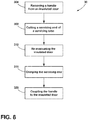
- a method 300 of servicing the insulated door 10 includes step 304 of removing the handle 50 from the insulated door 10. Removing the handle 50 provides access to the evacuation port assembly 118.
- the servicing end 46 of the servicing tube 38 is cut, thereby breaking the seal in the servicing tube 38 and providing access to the insulating cavity 30 of the insulated door 10.
- the insulated door 10 is re-evacuated.
- the evacuation device is engaged with the cut servicing end 46 of the servicing tube 38 to produce the desired pressure differential 110 after the at least partial vacuum 106 is drawn.
- step 316 the evacuation device is removed from the cut servicing end 46, and the cut servicing end 46 of the servicing tube 38 is again crimped or otherwise sealed to seal the insulating cavity 30.
- step 320 the handle 50 is coupled to the outer wrapper 18 over the evacuation port assembly 118.
- the insulated door 10 may be serviced any practicable number of times, which can depend on the length of the servicing tube 38.
- the insulated door 10 can be used in various appliances that can include, but are not limited to, refrigerators, freezers, coolers, ovens, dishwashers, laundry appliances, and other similar appliances and fixtures within household and commercial settings.
- the insulation materials 90 can be a free-flowing material that can be poured, blown, compacted, or otherwise disposed within the insulating cavity 30.
- This free-flowing material can be in the form of various silica-based materials, such as fumed silica, precipitated silica, nano-sized, and/or micro-sized aerogel powder, rice husk ash powder, perlite, glass spheres, hollow glass spheres, cenospheres, diatomaceous earth, combinations thereof, and other similar insulating particulate material.
- the evacuation port assembly 118 is coupled to the exterior surface 122 of the insulated door 10.
- the evacuation port assembly 118 maximizes space within the appliance 14, unlike conventional evacuation assemblies that are disposed on a liner and extend into the appliance 14.
- the handle 50 partially, or entirely, obscures the evacuation port assembly 118 from view.
- the handle 50 operates as a cover over the evacuation port assembly 118 to protect the components of the evacuation port assembly 118.
- the handle 50 operates to cover the evacuation port assembly 118 without an additional cover component added to the appliance 14. In this way, the insulated door 10 can reduce manufacturing and production costs. Additional benefits or advantages of using this device may also be realized and/or achieved.
- the device disclosed herein is further summarized in the following paragraphs and is further characterized by combinations of any and all of the various aspects described herein.
- a vacuum insulated door for an appliance includes an outer wrapper that defines an evacuation port.
- An inner liner is coupled to the outer wrapper defining an insulating cavity therebetween.
- a base is coupled to the outer wrapper adjacent to the evacuation port.
- a servicing tube has a connecting end and a servicing end. The servicing tube is in fluid communication with the insulating cavity via the evacuation port.
- the connecting end is coupled to the base.
- a handle has first and second ends coupled to the outer wrapper and a center portion therebetween spaced-apart from the outer wrapper. The first end is coupled to the outer wrapper proximate the evacuation port.
- the servicing tube extends along an inner surface of the handle.
- a handle is disposed over a base and a servicing tube.
- a servicing end of a servicing tube abuts an inner surface of a center portion of a handle and is spaced-apart from an outer wrapper.
- a handle defines an inner groove and a servicing tube extends at least partially into the inner groove.
- a handle includes sidewalls disposed on opposing sides of an inner groove.
- the sidewalls conceal a servicing tube.
- a servicing tube and an outer wrapper define an acute angle therebetween.
- a handle conceals a servicing tube.
- a connecting end of a servicing tube is curved to couple with a base.
- an insulated door assembly includes an outer wrapper that defines an evacuation port.
- An inner liner is coupled to the outer wrapper defining an insulating cavity therebetween.
- An evacuation port assembly includes a base coupled to the outer wrapper and a servicing tube coupled to the base.
- a handle has first and second ends coupled to the outer wrapper. The first end is disposed proximate the evacuation port and the servicing tube extends along the handle.
- a handle is disposed over an evacuation port assembly.
- a servicing tube extends along an inner surface of a handle.
- an attachment point between a first end of a handle and an outer wrapper is disposed adjacent to a base.
- a servicing tube includes a connecting end and a servicing end.
- An evacuation port assembly includes a connector disposed between a base and the connecting end of the servicing tube.
- a connecting end of a servicing tube is curved to couple with a connector.
- a handle defines an inner groove on an inner surface thereof.
- a servicing tube is at least partially disposed within the inner groove.
- an insulated structure includes a structural wrapper that has an insulating cavity.
- a handle assembly is coupled to the structural wrapper.
- the handle assembly includes an evacuation port in fluid communication with the insulating cavity. Gas can be expressed from the insulating cavity through the handle assembly.
- a handle assembly includes a base coupled to a structural wrapper, a servicing tube coupled to the base, and a handle coupled to the structural wrapper.
- a handle defines an inner groove and a servicing tube is disposed within the inner groove.
- a handle assembly includes a handle and a servicing tube.
- the servicing tube defines an evacuation path in fluid communication with an insulating cavity.
- an end of a handle and a connecting end of a servicing tube are coupled to a structural wrapper at a same attachment point.
- the term "coupled” in all of its forms, couple, coupling, coupled, etc. generally means the joining of two components (electrical or mechanical) directly or indirectly to one another. Such joining may be stationary in nature or movable in nature. Such joining may be achieved with the two components (electrical or mechanical) and any additional intermediate members being integrally formed as a single unitary body with one another or with the two components. Such joining may be permanent in nature or may be removable or releasable in nature unless otherwise stated.
Landscapes
- Engineering & Computer Science (AREA)
- Physics & Mathematics (AREA)
- Thermal Sciences (AREA)
- Civil Engineering (AREA)
- Structural Engineering (AREA)
- Chemical & Material Sciences (AREA)
- Combustion & Propulsion (AREA)
- Mechanical Engineering (AREA)
- General Engineering & Computer Science (AREA)
- Refrigerator Housings (AREA)
- Thermal Insulation (AREA)
Abstract
Description
- The present disclosure generally relates to an insulated door assembly, and more specifically, to a vacuum insulated door assembly for an appliance.
- According to one aspect of the present disclosure, a vacuum insulated door for an appliance includes an outer wrapper that defines an evacuation port. An inner liner is coupled to the outer wrapper defining an insulating cavity therebetween. A base is coupled to the outer wrapper adjacent to the evacuation port. A servicing tube has a connecting end and a servicing end. The servicing tube is in fluid communication with the insulating cavity via the evacuation port. The connecting end is coupled to the base. A handle has first and second ends coupled to the outer wrapper and a center portion therebetween spaced-apart from the outer wrapper. The first end is coupled to the outer wrapper proximate the evacuation port. The servicing tube extends along an inner surface of the handle.
- According to another aspect of the present disclosure, an insulated door assembly includes an outer wrapper defining an evacuation port. An inner liner is coupled to the outer wrapper defining an insulating cavity therebetween. An evacuation port assembly includes a base coupled to the outer wrapper and a servicing tube coupled to the base. A handle has first and second ends coupled to the outer wrapper. The first end is disposed proximate the evacuation port and the servicing tube extends along the handle.
- According to another aspect of the present disclosure, an insulated structure includes a structural wrapper that has an insulating cavity. A handle assembly is coupled to the structural wrapper. The handle assembly includes an evacuation port in fluid communication with the insulating cavity. Gas can be expressed from the insulating cavity through the handle assembly.
- These and other features, advantages, and objects of the present disclosure will be further understood and appreciated by those skilled in the art by reference to the following specification, claims, and appended drawings.
- In the drawings:
-
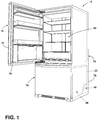
FIG. 1 is a front perspective view of an appliance with an insulated door, according to the present disclosure; -
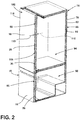
FIG. 2 is a cross-sectional view of the appliance with the insulated door ofFIG. 1 with the door closed; -
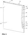
FIG. 3 is a front perspective view of an insulated door with an evacuation port assembly illustrated in phantom, according to the present disclosure; -
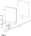
FIG. 4 is an exploded view of the insulated door ofFIG. 3 ; -
FIG. 5 is an enlarged view of the evacuation port assembly ofFIG. 3 with a handle illustrated in phantom; -
FIG. 6 is a cross-sectional view of a handle assembly of an insulated door having an evacuation port assembly with a handle illustrated in phantom, according to the present disclosure; -
FIG. 7 is a flow diagram of a method of assembling an insulated door, according to the present disclosure; and -
FIG. 8 is a flow diagram of a method of servicing an insulated door, according to the present disclosure. - The components in the figures are not necessarily to scale, emphasis instead being placed upon illustrating the principles described herein.
- The present illustrated embodiments reside primarily in combinations of method steps and apparatus components related to an evacuation port assembly. Accordingly, the apparatus components and method steps have been represented, where appropriate, by conventional symbols in the drawings, showing only those specific details that are pertinent to understanding the embodiments of the present disclosure so as not to obscure the disclosure with details that will be readily apparent to those of ordinary skill in the art having the benefit of the description herein. Further, like numerals in the description and drawings represent like elements.
- For purposes of description herein, the terms "upper," "lower," "right," "left," "rear," "front," "vertical," "horizontal," and derivatives thereof shall relate to the disclosure as oriented in
FIG. 1 . Unless stated otherwise, the term "front" shall refer to the surface of the element closer to an intended viewer, and the term "rear" shall refer to the surface of the element further from the intended viewer. However, it is to be understood that the disclosure may assume various alternative orientations, except where expressly specified to the contrary. It is also to be understood that the specific devices and processes illustrated in the attached drawings, and described in the following specification are simply exemplary embodiments of the inventive concepts defined in the appended claims. Hence, specific dimensions and other physical characteristics relating to the embodiments disclosed herein are not to be considered as limiting, unless the claims expressly state otherwise. - The terms "including," "comprises," "comprising," or any other variation thereof, are intended to cover a non-exclusive inclusion, such that a process, method, article, or apparatus that comprises a list of elements does not include only those elements but may include other elements not expressly listed or inherent to such process, method, article, or apparatus. An element proceeded by "comprises a ... " does not, without more constraints, preclude the existence of additional identical elements in the process, method, article, or apparatus that comprises the element.
- Referring to
FIGS. 1-8 ,reference numeral 10 generally designates an insulated door for anappliance 14 that includes anouter wrapper 18 defining anevacuation port 22. Aninner liner 26 is coupled to theouter wrapper 18 defining aninsulating cavity 30 therebetween. Abase 34 is coupled to theouter wrapper 18 adjacent to theevacuation port 22. Aservicing tube 38 has a connectingend 42 and aservicing end 46. Theservicing tube 38 is in fluid communication with theinsulating cavity 30 via theevacuation port 22. The connectingend 42 is coupled to thebase 34. Ahandle 50 has first andsecond ends outer wrapper 18 and acenter portion 62 therebetween spaced-apart from theouter wrapper 18. Thefirst end 54 is coupled to theouter wrapper 18 proximate theevacuation port 22. Theservicing tube 38 extends along aninner surface 66 of thehandle 50. - Referring to
FIGS. 1 and2 , theappliance 14 is illustrated as a refrigerating appliance, however, it is contemplated that the insulated door disclosed herein may be used with a variety of appliances, structures, or insulation purposes other than with an appliance. Moreover, the illustrated refrigerating appliance is a bottom mount refrigerator having the insulateddoor 10 and a second insulateddoor 70, which can have a substantially similar configuration as the insulateddoor 10 as discussed further herein. The insulateddoors - The insulated
door 10 is a vacuum insulated panel. As illustrated inFIGS. 1 and2 , the insulateddoor 10 includes theouter wrapper 18 coupled with theinner liner 26 defining theinsulating cavity 30 therebetween. Theouter wrapper 18 and theinner liner 26 may alternatively be referred to as a structural wrapper that defines theinsulating cavity 30. Acabinet 74 of theappliance 14 is typically an insulated structure having acabinet wrapper 78 and acabinet liner 82 with aninsulation cavity 86 defined therebetween. - Each of the
insulating cavity 30 of the insulateddoor 10 and theinsulation cavity 86 of thecabinet 74 typically includes one ormore insulation materials 90 disposed therein. It is generally contemplated that theinsulation materials 90 may be glass type materials, carbon-based powders, silicon oxide-based materials, silica-based materials, insulating gasses, and otherstandard insulation materials 90 known in the art. Theinsulation materials 90 substantially fill theinsulating cavity 30 forming a substantially continuous layer between theouter wrapper 18 and theinner liner 26. Similarly, theinsulation materials 90 substantially fill theinsulation cavity 86 forming a substantially continuous layer between thecabinet wrapper 78 and thecabinet liner 82. - In the depicted example of
FIGS. 1 and2 , theappliance 14 includes twoinsulated doors outer wrapper 18 coupled with theinner liner 26 to define the insulatingcavity 30. Theinsulated doors door 70 is illustrated as a drawer, it is considered a door for purposes of this application. Theinsulation materials 90 are disposed in each of the insulatingcavities 30. In this way, first andsecond compartments cabinet 74 can each be sealed with aninsulated door outer wrapper 18 and theinner liner 26 may be made from a material at least partially resistant to bending, deformation, or otherwise being formed in response to an inwardcompressive force 102. These materials for theouter wrapper 18 and theinner liner 26 include, but are not limited to, metals, polymers, metal alloys, combinations thereof, and/or other similar substantially rigid materials that can be used for vacuum insulated structures. - Referring still to
FIGS. 1 and2 , an at leastpartial vacuum 106 is defined within the insulatingcavity 30. The at leastpartial vacuum 106 defines a pressure differential 110 between an exterior 114 of theinsulated door 10 and the insulatingcavity 30. Thepressure differential 110 serves to define the inwardcompressive force 102 that is exerted on both theouter wrapper 18 and theinner liner 26 and tends to bias theouter wrapper 18 and theinner liner 26 toward the insulatingcavity 30. Over time, gas can infiltrate into the insulatingcavity 30 from an area outside theappliance 14, which can diminish the at leastpartial vacuum 106. The infiltration of gas is sometimes referred to as gas permeation, which can result in the at leastpartial vacuum 106 to decrease over time. - Referring to
FIGS. 2-4 , theouter wrapper 18 defines theevacuation port 22, which is an opening into the insulatingcavity 30. The at leastpartial vacuum 106 is typically defined by evacuation of theinsulated door 10 through theevacuation port 22 and anevacuation port assembly 118. Theevacuation port assembly 118 typically includes thebase 34 and theservicing tube 38. Theevacuation port assembly 118 is in fluid communication with the insulatingcavity 30 via theevacuation port 22 to expel gas from the insulatingcavity 30. Thebase 34 is coupled to theouter wrapper 18 adjacent to theevacuation port 22. Typically, the base 34 surrounds theevacuation port 22. The base 34 may be coupled to anexterior surface 122 of theouter wrapper 18, or alternatively, may be coupled to aninterior surface 126 of theouter wrapper 18, as best illustrated inFIG. 6 . - Referring still to
FIGS. 3 and4 , thebase 34 can be coupled to theouter wrapper 18 by various mechanisms and methods, including, but not limited to, projection, welding, resistance welding, adhering, or other coupling methods typically used with vacuum insulated structures. Thebase 34 is typically formed of a rigid material, such as metal or metal alloys. In non-limiting examples, thebase 34 can be configured as a steel washer. - The servicing
tube 38 is coupled to thebase 34 and extends from the base 34 away from theexterior surface 122 of theouter wrapper 18. The servicingtube 38 is typically formed from a metal material or another material that is generally rigid, while still being capable of compression, such as crimping. In non-limiting examples where thebase 34 is configured as a steel disk, such as a washer or nut, the servicingtube 38 can be brazed to thebase 34. The servicingtube 38 is in fluid communication with the insulatingcavity 30. According to various aspects, the servicingtube 38 defines an evacuation path 130 (FIG. 5 ), such that gas can be expressed from the insulatingcavity 30 and along theevacuation path 130 of theservicing tube 38. - Referring still to
FIGS. 3 and4 , theevacuation port assembly 118 may include aconnector 134 disposed between the base 34 and theservicing tube 38. In this way, theconnector 134 is coupled to thebase 34 and theservicing tube 38 is coupled to theconnector 134. Theconnector 134 can be coupled to theouter wrapper 18 and surround theevacuation port 22. Alternatively, theconnector 134 can extend at least partially through theevacuation port 22 into the insulatingcavity 30 to couple with thebase 34. - The
handle 50 includes the first and second ends 54, 58 coupled to theexterior surface 122 of theouter wrapper 18. Thecenter portion 62 of thehandle 50 is spaced-apart from theexterior surface 122 to define a grasping area for a user. Thehandle 50 is disposed over theevacuation port assembly 118 to substantially, or entirely, conceal and/or obscure theevacuation port assembly 118 from the view of the user. As illustrated, thefirst end 54 of thehandle 50 is coupled to theouter wrapper 18 proximate theevacuation port assembly 118 and theevacuation port 22. Thefirst end 54 is illustrated as a lower end of a vertically-orientedhandle 50. However, it is contemplated that the upper end (e.g., the second end 58) of a vertically-orientedhandle 50 may be disposed proximate theevacuation port assembly 118. Further, it is contemplated that thehandle 50 can be horizontally-oriented, or positioned at any angle relative to theinsulated door 10, and either of the first and second ends 54, 58 can be disposed proximate theevacuation port assembly 118. - Referring to
FIGS. 3 ,5, and 6 , thehandle 50 and theevacuation port assembly 118 form ahandle assembly 138 that operates to substantially provide access to the insulatingcavity 30, while obscuring theevacuation port assembly 118 from view. As illustrated, thehandle 50 slopes from thefirst end 54 to thecenter portion 62 and then slopes in a mirror image from thecenter portion 62 to thesecond end 58. Each of the sloping portions defined by thehandle 50 is typically substantially consistent, thereby defining acute angles θ1 between the sloping portions of thehandle 50 and theexterior surface 122 of theouter wrapper 18. - In the depicted example, the
base 34 is coupled to theinterior surface 126 of theouter wrapper 18. Theconnector 134 is coupled to thebase 34 and extends outward from theexterior surface 122. The servicingtube 38 includes the connectingend 42 coupled to theconnector 134. According to various aspects, the connectingend 42 is curved to couple with theconnector 134 and allow theservicing tube 38 to extend at an angle θ2 from theconnector 134. As illustrated, the servicingtube 38 and theexterior surface 122 of theouter wrapper 18 define an acute angle θ2 therebetween. The acute angle θ1 defined between thehandle 50 and theexterior surface 122 is substantially the same as the acute angle θ2 defined between the servicingtube 38 and theexterior surface 122. In this way, the servicingtube 38 extends away from theouter wrapper 18 at a substantially same orientation as thehandle 50. Moreover, the servicingtube 38 typically extends along theinner surface 66 of thehandle 50 for at least a portion of a length of thehandle 50 to further conceal theservicing tube 38 from view. The connectingend 42 of theservicing tube 38 is positioned proximate theexterior surface 122 of theouter wrapper 18 and thefirst end 54 of thehandle 50. The servicingend 46 of theservicing tube 38 abuts theinner surface 66 proximate of thecenter portion 62 thehandle 50 and is spaced-apart from theexterior surface 122 of theouter wrapper 18. - According to various aspects, the
handle 50 defines aninner groove 142 in theinner surface 66 thereof. Theinner groove 142 extends from at least one of the first and second ends 54, 58 for at least a portion of the length of thehandle 50. The servicingtube 38 extends at least partially into theinner groove 142. Thehandle 50 includessidewalls inner groove 142. Thesidewalls inner groove 142 to assist in obscuring theservicing tube 38 from view. Thesidewalls exterior surface 122 of theouter wrapper 18 than the servicingtube 38, thereby allowing theservicing tube 38 to be entirely positioned within theinner groove 142. - Referring still to
FIGS. 5 and 6 , thehandle 50 and theevacuation port assembly 118 are typically coupled to theouter wrapper 18 at substantially the same attachment point. This is advantageous for fully concealing and aligning theevacuation port assembly 118 with thehandle 50. Further, this is also advantageous for providing convenient assembly of thehandle assembly 138. - In various examples, the
handle assembly 138 can include theevacuation port 22, which provides access to the insulatingcavity 30. Thehandle assembly 138 includes at least the base 34 coupled to theouter wrapper 18, the servicingtube 38 coupled to thebase 34, and thehandle 50 coupled to theouter wrapper 18. Thehandle assembly 138 can further include theconnector 134. The servicingend 46 of theservicing tube 38 defines theevacuation port 22 and the connectingend 42 of theservicing tube 38 is in fluid communication with the insulatingcavity 30 through an additional opening in theouter wrapper 18. - Referring to
FIGS. 1-6 , theinsulated door 10 is generally formed using vacuum insulation technology. Theevacuation port 22 provides access to the insulatingcavity 30 in which thepressure differential 110 is defined after the at leastpartial vacuum 106 is drawn. A vacuum device is positioned around the servicingend 46 of theservicing tube 38 and draws the at leastpartial vacuum 106 through theservicing tube 38. Once the desired pressure differential 110 is defined between the insulatingcavity 30, theinner liner 26, and theouter wrapper 18 of theinsulated door 10, the servicingend 46 of theservicing tube 38 is crimped to seal theservicing tube 38, and ultimately, theinsulated door 10. A service technician can remove thehandle 50 from theinsulated door 10 to access theevacuation port assembly 118. The crimpedservicing end 46 of theservicing tube 38 is cut to provide access to the insulatingcavity 30. The at leastpartial vacuum 106 may be redrawn through theservicing tube 38 via thecut servicing end 46 to the desiredpressure differential 110. Once re-evacuated, the servicingend 46 is crimped again to seal theservicing tube 38 and theinsulated door 10. The service technician can then couple thehandle 50 to theinsulated door 10 to obscure theevacuation port assembly 118 from the view of the user. Theinsulated door 10 may be re-evacuated any practicable number of times through the same process, however, the number of re-evacuations depends on the length of theservicing tube 38. - Referring to
FIG. 7 , and with further reference toFIGS. 1-6 , amethod 200 of assembling theinsulated door 10 includesstep 204 of coupling theouter wrapper 18 to theinner liner 26. An insulating material (e.g., insulating materials 90) is also typically disposed within thecavity 30 Instep 208, theevacuation port assembly 118 is coupled with theouter wrapper 18. Typically, thebase 34 is coupled with theouter wrapper 18, theconnector 134 is coupled to thebase 34, and theservicing tube 38 is coupled to theconnector 134. Instep 212, theinsulated door 10 is evacuated to define the desired pressure differential 110 between the insulatingcavity 30 and theexterior 114 of theinsulated door 10. The evacuation device is positioned to engage, such as extend around, the servicingend 46 of theservicing tube 38. This places the evacuation device is in fluid communication with the insulatingcavity 30 to draw the at leastpartial vacuum 106 within theinsulated door 10. Instep 216, the servicingend 46 of theservicing tube 38 is crimped or otherwise sealed to seal the insulatingcavity 30 and retain the at leastpartial vacuum 106. Instep 220, thehandle 50 is positioned over theevacuation port assembly 118 and coupled to theexterior surface 122 of theouter wrapper 18. When thehandle 50 is coupled with theouter wrapper 18, the servicingtube 38 extends into theinner groove 142 of thehandle 50. In this way, thehandle 50 is coupled to theouter wrapper 18 in a manner that substantially, or entirely, conceals theevacuation port assembly 118. - Referring to
FIG. 8 , and with further reference toFIGS. 1-7 , a method 300 of servicing theinsulated door 10 includesstep 304 of removing thehandle 50 from theinsulated door 10. Removing thehandle 50 provides access to theevacuation port assembly 118. Instep 308, the servicingend 46 of theservicing tube 38 is cut, thereby breaking the seal in theservicing tube 38 and providing access to the insulatingcavity 30 of theinsulated door 10. Instep 312, theinsulated door 10 is re-evacuated. The evacuation device is engaged with thecut servicing end 46 of theservicing tube 38 to produce the desired pressure differential 110 after the at leastpartial vacuum 106 is drawn. Instep 316, the evacuation device is removed from thecut servicing end 46, and thecut servicing end 46 of theservicing tube 38 is again crimped or otherwise sealed to seal the insulatingcavity 30. Instep 320, thehandle 50 is coupled to theouter wrapper 18 over theevacuation port assembly 118. Theinsulated door 10 may be serviced any practicable number of times, which can depend on the length of theservicing tube 38. - According to various examples, the
insulated door 10 can be used in various appliances that can include, but are not limited to, refrigerators, freezers, coolers, ovens, dishwashers, laundry appliances, and other similar appliances and fixtures within household and commercial settings. Additionally, theinsulation materials 90 can be a free-flowing material that can be poured, blown, compacted, or otherwise disposed within the insulatingcavity 30. This free-flowing material can be in the form of various silica-based materials, such as fumed silica, precipitated silica, nano-sized, and/or micro-sized aerogel powder, rice husk ash powder, perlite, glass spheres, hollow glass spheres, cenospheres, diatomaceous earth, combinations thereof, and other similar insulating particulate material. - Referring to
FIGS. 1-8 , the present disclosure provides a variety of advantages. For example, theevacuation port assembly 118 is coupled to theexterior surface 122 of theinsulated door 10. In this way, theevacuation port assembly 118 maximizes space within theappliance 14, unlike conventional evacuation assemblies that are disposed on a liner and extend into theappliance 14. Further, thehandle 50 partially, or entirely, obscures theevacuation port assembly 118 from view. Moreover, thehandle 50 operates as a cover over theevacuation port assembly 118 to protect the components of theevacuation port assembly 118. Additionally, thehandle 50 operates to cover theevacuation port assembly 118 without an additional cover component added to theappliance 14. In this way, theinsulated door 10 can reduce manufacturing and production costs. Additional benefits or advantages of using this device may also be realized and/or achieved. - The device disclosed herein is further summarized in the following paragraphs and is further characterized by combinations of any and all of the various aspects described herein.
- According to an aspect of the present disclosure, a vacuum insulated door for an appliance includes an outer wrapper that defines an evacuation port. An inner liner is coupled to the outer wrapper defining an insulating cavity therebetween. A base is coupled to the outer wrapper adjacent to the evacuation port. A servicing tube has a connecting end and a servicing end. The servicing tube is in fluid communication with the insulating cavity via the evacuation port. The connecting end is coupled to the base. A handle has first and second ends coupled to the outer wrapper and a center portion therebetween spaced-apart from the outer wrapper. The first end is coupled to the outer wrapper proximate the evacuation port. The servicing tube extends along an inner surface of the handle.
- According to another aspect, a handle is disposed over a base and a servicing tube.
- According to another aspect, a servicing end of a servicing tube abuts an inner surface of a center portion of a handle and is spaced-apart from an outer wrapper.
- According to another aspect, a handle defines an inner groove and a servicing tube extends at least partially into the inner groove.
- According to another aspect, a handle includes sidewalls disposed on opposing sides of an inner groove. The sidewalls conceal a servicing tube.
- According to another aspect, a servicing tube and an outer wrapper define an acute angle therebetween.
- According to another aspect, a handle conceals a servicing tube.
- According to another aspect, a connecting end of a servicing tube is curved to couple with a base.
- According to another aspect of the present disclosure, an insulated door assembly includes an outer wrapper that defines an evacuation port. An inner liner is coupled to the outer wrapper defining an insulating cavity therebetween. An evacuation port assembly includes a base coupled to the outer wrapper and a servicing tube coupled to the base. A handle has first and second ends coupled to the outer wrapper. The first end is disposed proximate the evacuation port and the servicing tube extends along the handle.
- According to another aspect, a handle is disposed over an evacuation port assembly.
- According to another aspect, a servicing tube extends along an inner surface of a handle.
- According to another aspect, an attachment point between a first end of a handle and an outer wrapper is disposed adjacent to a base.
- According to another aspect, a servicing tube includes a connecting end and a servicing end. An evacuation port assembly includes a connector disposed between a base and the connecting end of the servicing tube.
- According to another aspect, a connecting end of a servicing tube is curved to couple with a connector.
- According to another aspect, a handle defines an inner groove on an inner surface thereof. A servicing tube is at least partially disposed within the inner groove.
- According to another aspect of the present disclosure, an insulated structure includes a structural wrapper that has an insulating cavity. A handle assembly is coupled to the structural wrapper. The handle assembly includes an evacuation port in fluid communication with the insulating cavity. Gas can be expressed from the insulating cavity through the handle assembly.
- According to another aspect, a handle assembly includes a base coupled to a structural wrapper, a servicing tube coupled to the base, and a handle coupled to the structural wrapper.
- According to another aspect, a handle defines an inner groove and a servicing tube is disposed within the inner groove.
- According to another aspect, a handle assembly includes a handle and a servicing tube.
- The servicing tube defines an evacuation path in fluid communication with an insulating cavity.
- According to another aspect, an end of a handle and a connecting end of a servicing tube are coupled to a structural wrapper at a same attachment point.
- For purposes of this disclosure, the term "coupled" (in all of its forms, couple, coupling, coupled, etc.) generally means the joining of two components (electrical or mechanical) directly or indirectly to one another. Such joining may be stationary in nature or movable in nature. Such joining may be achieved with the two components (electrical or mechanical) and any additional intermediate members being integrally formed as a single unitary body with one another or with the two components. Such joining may be permanent in nature or may be removable or releasable in nature unless otherwise stated.
Claims (15)
- An insulated structure (10), comprising:a structural wrapper (18, 26) having an insulating cavity (30); anda handle assembly (138) coupled to the structural wrapper (18, 26), wherein the handle assembly (138) includes an evacuation port (22) in fluid communication with the insulating cavity (30), wherein gas can be expressed from the insulating cavity (30) through the handle assembly (138).
- The insulated structure (10) of claim 1, wherein the handle assembly (138) includes a base (34) coupled to the structural wrapper (18, 26), a servicing tube (38) coupled to the base (34), and a handle (50) coupled to the structural wrapper (18, 26).
- The insulated structure (10) of claim 2, wherein the handle (50) defines an inner groove (142) and the servicing tube (38) is disposed within the inner groove (142).
- The insulated structure (10) of claim 2 or claim 3, wherein the servicing tube (38) extends along an inner surface (66) of the handle (50).
- The insulated structure (10) of any of claims 2-4, wherein the handle (50) conceals the servicing tube (38).
- The insulated structure (10) of any of claims 2-5, wherein an attachment point between a first end (54) of the handle (50) and the structural wrapper (18, 26) is disposed adjacent to the base (34).
- The insulated structure (10) of any of claims 2-6, wherein the servicing tube (38) includes a connecting end (42) and a servicing end (46), and wherein the evacuation port (22) further comprises a connector (134) disposed between the base (34) and the connecting end (42) of the servicing tube (38).
- The insulated structure (10) of claim 7, wherein the connecting end (42) of the servicing tube (38) is curved to couple with the connector (134).
- The insulated structure (10) of claim 1, wherein the handle assembly (138) includes a handle (50) and a servicing tube (38), and wherein the servicing tube (38) defines an evacuation path (130) in fluid communication with the insulating cavity (30).
- The insulated structure (10) of claim 9, wherein an end (54, 58) of the handle (50) and a connecting end (42) of the servicing tube (38) are coupled to the structural wrapper (18, 26) at a same attachment point.
- The insulated structure (10) of claim 1, further comprising:
a servicing tube (38) having a connecting end (42) and a servicing end (46), wherein the servicing tube (38) is in fluid communication with the insulating cavity (30) via the evacuation port (22). - The insulated structure (10) of any of claims 2-11, wherein the handle (50) includes sidewalls (146, 150) disposed on opposing sides of an inner groove (142), and wherein the sidewalls (146, 150) conceal the servicing tube (38).
- The insulated structure (10) of any of claims 1-12, wherein the handle (50) includes first and second ends (54, 58) coupled to the structural wrapper (18, 26) and a center portion (62) therebetween spaced-apart from the structural wrapper (18, 26), wherein the first end (54) is coupled to the structural wrapper (18, 26) proximate the evacuation port (22).
- The insulated structure (10) of claim 13, wherein a servicing end (46) of the servicing tube (38) abuts an inner surface (66) of the center portion (62) of the handle (50) and is spaced-apart from the structural wrapper (18, 26).
- An appliance (14) comprising the insulated structure (10) of any of claims 1-14.
Applications Claiming Priority (1)
| Application Number | Priority Date | Filing Date | Title |
|---|---|---|---|
| US16/716,773 US11021905B1 (en) | 2019-12-17 | 2019-12-17 | Insulated door assembly |
Publications (2)
| Publication Number | Publication Date |
|---|---|
| EP3839385A1 true EP3839385A1 (en) | 2021-06-23 |
| EP3839385B1 EP3839385B1 (en) | 2023-05-17 |
Family
ID=73059479
Family Applications (1)
| Application Number | Title | Priority Date | Filing Date |
|---|---|---|---|
| EP20205304.7A Active EP3839385B1 (en) | 2019-12-17 | 2020-11-02 | Insulated door assembly |
Country Status (3)
| Country | Link |
|---|---|
| US (5) | US11021905B1 (en) |
| EP (1) | EP3839385B1 (en) |
| CN (1) | CN112984930B (en) |
Families Citing this family (6)
| Publication number | Priority date | Publication date | Assignee | Title |
|---|---|---|---|---|
| US10907890B2 (en) * | 2016-04-14 | 2021-02-02 | Whirlpool Corporation | Double cabinet vacuum insulated refrigerator with a structural foamed mullion |
| KR102568407B1 (en) * | 2018-06-27 | 2023-08-21 | 엘지전자 주식회사 | Vacuum adiabatic body and refrigerator |
| US11021905B1 (en) * | 2019-12-17 | 2021-06-01 | Whirlpool Corporation | Insulated door assembly |
| US12264872B2 (en) * | 2022-10-24 | 2025-04-01 | Whirlpool Corporation | Insulation panel assembly for a refrigeration unit |
| MX2024001180A (en) * | 2023-01-25 | 2024-07-26 | Hussmann Corp | Door panel for a merchandiser. |
| US12624886B2 (en) | 2023-11-01 | 2026-05-12 | Whirlpool Corporation | Vacuum port cover and aligner features |
Citations (2)
| Publication number | Priority date | Publication date | Assignee | Title |
|---|---|---|---|---|
| KR19990013946U (en) * | 1997-09-30 | 1999-04-26 | 전주범 | Door Handle Assembly Structure of Refrigerator |
| US20150013352A1 (en) * | 2013-07-09 | 2015-01-15 | Eppendorf Ag | Unified Freezer Chamber Venting with Door Handle |
Family Cites Families (27)
| Publication number | Priority date | Publication date | Assignee | Title |
|---|---|---|---|---|
| US2753695A (en) | 1953-10-07 | 1956-07-10 | James A Maranto | Mechanical refrigerator |
| JPH04366094A (en) | 1991-06-13 | 1992-12-17 | Kubota Corp | Powder vacuum insulator |
| JP2672204B2 (en) | 1991-06-13 | 1997-11-05 | 株式会社クボタ | Powder vacuum insulation |
| SE470464B (en) | 1992-09-10 | 1994-04-18 | Electrolux Res & Innovation | Insulation for refrigerators or freezers |
| SE501701C2 (en) | 1993-09-29 | 1995-04-24 | Electrolux Ab | Ways to fill and pack insulating powder into the walls of a cabinet body |
| SE505193C2 (en) | 1993-12-22 | 1997-07-14 | Electrolux Ab | Box comprising vacuum-insulated walls of a refrigerator or freezer |
| US6106449A (en) | 1996-12-23 | 2000-08-22 | Vacupanel, Inc. | Vacuum insulated panel and container and method of production |
| US6109712A (en) * | 1998-07-16 | 2000-08-29 | Maytag Corporation | Integrated vacuum panel insulation for thermal cabinet structures |
| CN1325864C (en) | 2002-03-13 | 2007-07-11 | 松下冷机株式会社 | Refrigerator |
| TR200604994T1 (en) | 2004-03-22 | 2007-01-22 | Arçeli̇k Anoni̇m Şi̇rketi̇ | A cooler and insulation improvement method. |
| CN203095854U (en) * | 2013-01-25 | 2013-07-31 | 李梦琪 | Insulating colored crystal glass and freezer |
| CN105300012B (en) * | 2014-06-19 | 2017-10-17 | 南京创维家用电器有限公司 | Glass door for refrigerator vacuum fixture and refrigerator |
| DE102015008123A1 (en) | 2014-11-25 | 2016-05-25 | Liebherr-Hausgeräte Lienz Gmbh | Vakuumdämmkörper |
| US10161669B2 (en) * | 2015-03-05 | 2018-12-25 | Whirlpool Corporation | Attachment arrangement for vacuum insulated door |
| US9791205B2 (en) * | 2015-12-09 | 2017-10-17 | Whirlpool Corporation | Insulating material with renewable resource component |
| EP3491309B1 (en) * | 2016-07-26 | 2021-02-24 | Whirlpool Corporation | Method for ensuring reliable core material fill around the pass throughs in a vacuum insulated structure |
| CN106595197B (en) * | 2016-10-31 | 2019-04-12 | 常熟市久昇电器有限公司 | A kind of refrigerator combination hollow glass door |
| WO2018136054A1 (en) * | 2017-01-18 | 2018-07-26 | Whirlpool Corporation | Use of rigid or permeable conduits for achieving faster vacuum evacuation time in vacuum insulated structures |
| EP3571451B1 (en) * | 2017-01-18 | 2021-10-13 | Whirlpool Corporation | Increased vacuum port area for achieving faster vacuum evacuation time in vacuum insulated structures |
| EP3571453B1 (en) | 2017-01-18 | 2023-05-24 | Whirlpool Corporation | Use of edge located channels for achieving faster vacuum evacuation time in vacuum insulated structures |
| US11300354B2 (en) * | 2017-10-05 | 2022-04-12 | Whirlpool Corporation | Filling ports for insulated structures incorporated within an appliance |
| CN108679918B (en) * | 2018-05-31 | 2023-12-22 | 惠而浦(中国)股份有限公司 | Sealing structure for refrigerator vacuum chamber |
| US10746343B2 (en) * | 2018-09-28 | 2020-08-18 | Whirlpool Corporation | Channel system for a vacuum insulated structure |
| US11300238B2 (en) * | 2019-01-21 | 2022-04-12 | Whirlpool Corporation | Vacuum insulated structure with filter features in a vacuum cavity |
| US10697696B1 (en) * | 2019-02-25 | 2020-06-30 | Whirlpool Corporation | Vacuum insulated structure with internal airway system |
| US10995488B1 (en) * | 2019-11-20 | 2021-05-04 | Whirlpool Corporation | Servicing assembly for an insulated structure |
| US11021905B1 (en) * | 2019-12-17 | 2021-06-01 | Whirlpool Corporation | Insulated door assembly |
-
2019
- 2019-12-17 US US16/716,773 patent/US11021905B1/en active Active
-
2020
- 2020-11-02 EP EP20205304.7A patent/EP3839385B1/en active Active
- 2020-12-15 CN CN202011472579.3A patent/CN112984930B/en active Active
-
2021
- 2021-03-30 US US17/216,900 patent/US11414918B2/en active Active
-
2022
- 2022-06-29 US US17/852,799 patent/US11692387B2/en active Active
-
2023
- 2023-05-19 US US18/199,471 patent/US12049784B2/en active Active
-
2024
- 2024-06-28 US US18/757,957 patent/US20240352784A1/en not_active Abandoned
Patent Citations (2)
| Publication number | Priority date | Publication date | Assignee | Title |
|---|---|---|---|---|
| KR19990013946U (en) * | 1997-09-30 | 1999-04-26 | 전주범 | Door Handle Assembly Structure of Refrigerator |
| US20150013352A1 (en) * | 2013-07-09 | 2015-01-15 | Eppendorf Ag | Unified Freezer Chamber Venting with Door Handle |
Also Published As
| Publication number | Publication date |
|---|---|
| EP3839385B1 (en) | 2023-05-17 |
| US11692387B2 (en) | 2023-07-04 |
| US20230287729A1 (en) | 2023-09-14 |
| US11414918B2 (en) | 2022-08-16 |
| US12049784B2 (en) | 2024-07-30 |
| CN112984930A (en) | 2021-06-18 |
| US20220325572A1 (en) | 2022-10-13 |
| CN112984930B (en) | 2024-11-15 |
| US11021905B1 (en) | 2021-06-01 |
| US20240352784A1 (en) | 2024-10-24 |
| US20210214993A1 (en) | 2021-07-15 |
Similar Documents
| Publication | Publication Date | Title |
|---|---|---|
| EP3839385B1 (en) | Insulated door assembly | |
| US11427998B2 (en) | Servicing assembly for an insulated structure | |
| US11940205B2 (en) | Vacuum insulated structure | |
| US11480385B2 (en) | Vacuum insulated panel for counteracting vacuum bow induced deformations | |
| US20240319032A1 (en) | Sensor assembly for vacuum insulated structure | |
| CN113771284B (en) | Fill port for insulation structures incorporated within an appliance | |
| US20240401870A1 (en) | Connector assembly for vacuum insulated structures | |
| EP4502511A1 (en) | Support system for a vacuum insulated panel | |
| EP3792575A1 (en) | Standoff assembly for an appliance | |
| US20190264859A1 (en) | Vacuum insulated structures having internal chamber structures | |
| US12535260B2 (en) | Trimbreaker ladder cover |
Legal Events
| Date | Code | Title | Description |
|---|---|---|---|
| PUAI | Public reference made under article 153(3) epc to a published international application that has entered the european phase |
Free format text: ORIGINAL CODE: 0009012 |
|
| STAA | Information on the status of an ep patent application or granted ep patent |
Free format text: STATUS: THE APPLICATION HAS BEEN PUBLISHED |
|
| AK | Designated contracting states |
Kind code of ref document: A1 Designated state(s): AL AT BE BG CH CY CZ DE DK EE ES FI FR GB GR HR HU IE IS IT LI LT LU LV MC MK MT NL NO PL PT RO RS SE SI SK SM TR |
|
| STAA | Information on the status of an ep patent application or granted ep patent |
Free format text: STATUS: REQUEST FOR EXAMINATION WAS MADE |
|
| 17P | Request for examination filed |
Effective date: 20211222 |
|
| RBV | Designated contracting states (corrected) |
Designated state(s): AL AT BE BG CH CY CZ DE DK EE ES FI FR GB GR HR HU IE IS IT LI LT LU LV MC MK MT NL NO PL PT RO RS SE SI SK SM TR |
|
| GRAP | Despatch of communication of intention to grant a patent |
Free format text: ORIGINAL CODE: EPIDOSNIGR1 |
|
| STAA | Information on the status of an ep patent application or granted ep patent |
Free format text: STATUS: GRANT OF PATENT IS INTENDED |
|
| RIC1 | Information provided on ipc code assigned before grant |
Ipc: F25D 23/02 20060101AFI20230116BHEP |
|
| INTG | Intention to grant announced |
Effective date: 20230220 |
|
| GRAS | Grant fee paid |
Free format text: ORIGINAL CODE: EPIDOSNIGR3 |
|
| GRAA | (expected) grant |
Free format text: ORIGINAL CODE: 0009210 |
|
| STAA | Information on the status of an ep patent application or granted ep patent |
Free format text: STATUS: THE PATENT HAS BEEN GRANTED |
|
| AK | Designated contracting states |
Kind code of ref document: B1 Designated state(s): AL AT BE BG CH CY CZ DE DK EE ES FI FR GB GR HR HU IE IS IT LI LT LU LV MC MK MT NL NO PL PT RO RS SE SI SK SM TR |
|
| REG | Reference to a national code |
Ref country code: GB Ref legal event code: FG4D |
|
| REG | Reference to a national code |
Ref country code: DE Ref legal event code: R096 Ref document number: 602020010929 Country of ref document: DE |
|
| REG | Reference to a national code |
Ref country code: CH Ref legal event code: EP |
|
| REG | Reference to a national code |
Ref country code: IE Ref legal event code: FG4D |
|
| REG | Reference to a national code |
Ref country code: AT Ref legal event code: REF Ref document number: 1568536 Country of ref document: AT Kind code of ref document: T Effective date: 20230615 |
|
| P01 | Opt-out of the competence of the unified patent court (upc) registered |
Effective date: 20230530 |
|
| REG | Reference to a national code |
Ref country code: LT Ref legal event code: MG9D |
|
| REG | Reference to a national code |
Ref country code: NL Ref legal event code: MP Effective date: 20230517 |
|
| REG | Reference to a national code |
Ref country code: AT Ref legal event code: MK05 Ref document number: 1568536 Country of ref document: AT Kind code of ref document: T Effective date: 20230517 |
|
| PG25 | Lapsed in a contracting state [announced via postgrant information from national office to epo] |
Ref country code: SE Free format text: LAPSE BECAUSE OF FAILURE TO SUBMIT A TRANSLATION OF THE DESCRIPTION OR TO PAY THE FEE WITHIN THE PRESCRIBED TIME-LIMIT Effective date: 20230517 Ref country code: PT Free format text: LAPSE BECAUSE OF FAILURE TO SUBMIT A TRANSLATION OF THE DESCRIPTION OR TO PAY THE FEE WITHIN THE PRESCRIBED TIME-LIMIT Effective date: 20230918 Ref country code: NO Free format text: LAPSE BECAUSE OF FAILURE TO SUBMIT A TRANSLATION OF THE DESCRIPTION OR TO PAY THE FEE WITHIN THE PRESCRIBED TIME-LIMIT Effective date: 20230817 Ref country code: NL Free format text: LAPSE BECAUSE OF FAILURE TO SUBMIT A TRANSLATION OF THE DESCRIPTION OR TO PAY THE FEE WITHIN THE PRESCRIBED TIME-LIMIT Effective date: 20230517 Ref country code: ES Free format text: LAPSE BECAUSE OF FAILURE TO SUBMIT A TRANSLATION OF THE DESCRIPTION OR TO PAY THE FEE WITHIN THE PRESCRIBED TIME-LIMIT Effective date: 20230517 Ref country code: AT Free format text: LAPSE BECAUSE OF FAILURE TO SUBMIT A TRANSLATION OF THE DESCRIPTION OR TO PAY THE FEE WITHIN THE PRESCRIBED TIME-LIMIT Effective date: 20230517 |
|
| PG25 | Lapsed in a contracting state [announced via postgrant information from national office to epo] |
Ref country code: RS Free format text: LAPSE BECAUSE OF FAILURE TO SUBMIT A TRANSLATION OF THE DESCRIPTION OR TO PAY THE FEE WITHIN THE PRESCRIBED TIME-LIMIT Effective date: 20230517 Ref country code: PL Free format text: LAPSE BECAUSE OF FAILURE TO SUBMIT A TRANSLATION OF THE DESCRIPTION OR TO PAY THE FEE WITHIN THE PRESCRIBED TIME-LIMIT Effective date: 20230517 Ref country code: LV Free format text: LAPSE BECAUSE OF FAILURE TO SUBMIT A TRANSLATION OF THE DESCRIPTION OR TO PAY THE FEE WITHIN THE PRESCRIBED TIME-LIMIT Effective date: 20230517 Ref country code: LT Free format text: LAPSE BECAUSE OF FAILURE TO SUBMIT A TRANSLATION OF THE DESCRIPTION OR TO PAY THE FEE WITHIN THE PRESCRIBED TIME-LIMIT Effective date: 20230517 Ref country code: IS Free format text: LAPSE BECAUSE OF FAILURE TO SUBMIT A TRANSLATION OF THE DESCRIPTION OR TO PAY THE FEE WITHIN THE PRESCRIBED TIME-LIMIT Effective date: 20230917 Ref country code: HR Free format text: LAPSE BECAUSE OF FAILURE TO SUBMIT A TRANSLATION OF THE DESCRIPTION OR TO PAY THE FEE WITHIN THE PRESCRIBED TIME-LIMIT Effective date: 20230517 Ref country code: GR Free format text: LAPSE BECAUSE OF FAILURE TO SUBMIT A TRANSLATION OF THE DESCRIPTION OR TO PAY THE FEE WITHIN THE PRESCRIBED TIME-LIMIT Effective date: 20230818 |
|
| PG25 | Lapsed in a contracting state [announced via postgrant information from national office to epo] |
Ref country code: FI Free format text: LAPSE BECAUSE OF FAILURE TO SUBMIT A TRANSLATION OF THE DESCRIPTION OR TO PAY THE FEE WITHIN THE PRESCRIBED TIME-LIMIT Effective date: 20230517 |
|
| PG25 | Lapsed in a contracting state [announced via postgrant information from national office to epo] |
Ref country code: SK Free format text: LAPSE BECAUSE OF FAILURE TO SUBMIT A TRANSLATION OF THE DESCRIPTION OR TO PAY THE FEE WITHIN THE PRESCRIBED TIME-LIMIT Effective date: 20230517 |
|
| PG25 | Lapsed in a contracting state [announced via postgrant information from national office to epo] |
Ref country code: SM Free format text: LAPSE BECAUSE OF FAILURE TO SUBMIT A TRANSLATION OF THE DESCRIPTION OR TO PAY THE FEE WITHIN THE PRESCRIBED TIME-LIMIT Effective date: 20230517 Ref country code: SK Free format text: LAPSE BECAUSE OF FAILURE TO SUBMIT A TRANSLATION OF THE DESCRIPTION OR TO PAY THE FEE WITHIN THE PRESCRIBED TIME-LIMIT Effective date: 20230517 Ref country code: RO Free format text: LAPSE BECAUSE OF FAILURE TO SUBMIT A TRANSLATION OF THE DESCRIPTION OR TO PAY THE FEE WITHIN THE PRESCRIBED TIME-LIMIT Effective date: 20230517 Ref country code: EE Free format text: LAPSE BECAUSE OF FAILURE TO SUBMIT A TRANSLATION OF THE DESCRIPTION OR TO PAY THE FEE WITHIN THE PRESCRIBED TIME-LIMIT Effective date: 20230517 Ref country code: DK Free format text: LAPSE BECAUSE OF FAILURE TO SUBMIT A TRANSLATION OF THE DESCRIPTION OR TO PAY THE FEE WITHIN THE PRESCRIBED TIME-LIMIT Effective date: 20230517 Ref country code: CZ Free format text: LAPSE BECAUSE OF FAILURE TO SUBMIT A TRANSLATION OF THE DESCRIPTION OR TO PAY THE FEE WITHIN THE PRESCRIBED TIME-LIMIT Effective date: 20230517 |
|
| PGFP | Annual fee paid to national office [announced via postgrant information from national office to epo] |
Ref country code: IT Payment date: 20231130 Year of fee payment: 4 |
|
| REG | Reference to a national code |
Ref country code: DE Ref legal event code: R097 Ref document number: 602020010929 Country of ref document: DE |
|
| PLBE | No opposition filed within time limit |
Free format text: ORIGINAL CODE: 0009261 |
|
| STAA | Information on the status of an ep patent application or granted ep patent |
Free format text: STATUS: NO OPPOSITION FILED WITHIN TIME LIMIT |
|
| 26N | No opposition filed |
Effective date: 20240220 |
|
| PG25 | Lapsed in a contracting state [announced via postgrant information from national office to epo] |
Ref country code: SI Free format text: LAPSE BECAUSE OF FAILURE TO SUBMIT A TRANSLATION OF THE DESCRIPTION OR TO PAY THE FEE WITHIN THE PRESCRIBED TIME-LIMIT Effective date: 20230517 |
|
| PG25 | Lapsed in a contracting state [announced via postgrant information from national office to epo] |
Ref country code: SI Free format text: LAPSE BECAUSE OF FAILURE TO SUBMIT A TRANSLATION OF THE DESCRIPTION OR TO PAY THE FEE WITHIN THE PRESCRIBED TIME-LIMIT Effective date: 20230517 |
|
| REG | Reference to a national code |
Ref country code: CH Ref legal event code: PL |
|
| PG25 | Lapsed in a contracting state [announced via postgrant information from national office to epo] |
Ref country code: MC Free format text: LAPSE BECAUSE OF FAILURE TO SUBMIT A TRANSLATION OF THE DESCRIPTION OR TO PAY THE FEE WITHIN THE PRESCRIBED TIME-LIMIT Effective date: 20230517 |
|
| PG25 | Lapsed in a contracting state [announced via postgrant information from national office to epo] |
Ref country code: LU Free format text: LAPSE BECAUSE OF NON-PAYMENT OF DUE FEES Effective date: 20231102 |
|
| PG25 | Lapsed in a contracting state [announced via postgrant information from national office to epo] |
Ref country code: CH Free format text: LAPSE BECAUSE OF NON-PAYMENT OF DUE FEES Effective date: 20231130 |
|
| PG25 | Lapsed in a contracting state [announced via postgrant information from national office to epo] |
Ref country code: MC Free format text: LAPSE BECAUSE OF FAILURE TO SUBMIT A TRANSLATION OF THE DESCRIPTION OR TO PAY THE FEE WITHIN THE PRESCRIBED TIME-LIMIT Effective date: 20230517 Ref country code: LU Free format text: LAPSE BECAUSE OF NON-PAYMENT OF DUE FEES Effective date: 20231102 Ref country code: CH Free format text: LAPSE BECAUSE OF NON-PAYMENT OF DUE FEES Effective date: 20231130 |
|
| REG | Reference to a national code |
Ref country code: BE Ref legal event code: MM Effective date: 20231130 |
|
| REG | Reference to a national code |
Ref country code: IE Ref legal event code: MM4A |
|
| PG25 | Lapsed in a contracting state [announced via postgrant information from national office to epo] |
Ref country code: IE Free format text: LAPSE BECAUSE OF NON-PAYMENT OF DUE FEES Effective date: 20231102 |
|
| PG25 | Lapsed in a contracting state [announced via postgrant information from national office to epo] |
Ref country code: BE Free format text: LAPSE BECAUSE OF NON-PAYMENT OF DUE FEES Effective date: 20231130 |
|
| PG25 | Lapsed in a contracting state [announced via postgrant information from national office to epo] |
Ref country code: IE Free format text: LAPSE BECAUSE OF NON-PAYMENT OF DUE FEES Effective date: 20231102 Ref country code: BE Free format text: LAPSE BECAUSE OF NON-PAYMENT OF DUE FEES Effective date: 20231130 |
|
| PG25 | Lapsed in a contracting state [announced via postgrant information from national office to epo] |
Ref country code: BG Free format text: LAPSE BECAUSE OF FAILURE TO SUBMIT A TRANSLATION OF THE DESCRIPTION OR TO PAY THE FEE WITHIN THE PRESCRIBED TIME-LIMIT Effective date: 20230517 |
|
| PG25 | Lapsed in a contracting state [announced via postgrant information from national office to epo] |
Ref country code: BG Free format text: LAPSE BECAUSE OF FAILURE TO SUBMIT A TRANSLATION OF THE DESCRIPTION OR TO PAY THE FEE WITHIN THE PRESCRIBED TIME-LIMIT Effective date: 20230517 |
|
| PGFP | Annual fee paid to national office [announced via postgrant information from national office to epo] |
Ref country code: DE Payment date: 20241128 Year of fee payment: 5 |
|
| PGFP | Annual fee paid to national office [announced via postgrant information from national office to epo] |
Ref country code: GB Payment date: 20241126 Year of fee payment: 5 |
|
| PGFP | Annual fee paid to national office [announced via postgrant information from national office to epo] |
Ref country code: FR Payment date: 20241126 Year of fee payment: 5 |
|
| PG25 | Lapsed in a contracting state [announced via postgrant information from national office to epo] |
Ref country code: CY Free format text: LAPSE BECAUSE OF FAILURE TO SUBMIT A TRANSLATION OF THE DESCRIPTION OR TO PAY THE FEE WITHIN THE PRESCRIBED TIME-LIMIT; INVALID AB INITIO Effective date: 20201102 |
|
| PG25 | Lapsed in a contracting state [announced via postgrant information from national office to epo] |
Ref country code: HU Free format text: LAPSE BECAUSE OF FAILURE TO SUBMIT A TRANSLATION OF THE DESCRIPTION OR TO PAY THE FEE WITHIN THE PRESCRIBED TIME-LIMIT; INVALID AB INITIO Effective date: 20201102 |
|
| PG25 | Lapsed in a contracting state [announced via postgrant information from national office to epo] |
Ref country code: IT Free format text: LAPSE BECAUSE OF NON-PAYMENT OF DUE FEES Effective date: 20241102 |
|
| PG25 | Lapsed in a contracting state [announced via postgrant information from national office to epo] |
Ref country code: TR Free format text: LAPSE BECAUSE OF FAILURE TO SUBMIT A TRANSLATION OF THE DESCRIPTION OR TO PAY THE FEE WITHIN THE PRESCRIBED TIME-LIMIT Effective date: 20230517 |