EP3839363A1 - A method for providing a diagnostic assessment of a chiller - Google Patents
A method for providing a diagnostic assessment of a chiller Download PDFInfo
- Publication number
- EP3839363A1 EP3839363A1 EP20214011.7A EP20214011A EP3839363A1 EP 3839363 A1 EP3839363 A1 EP 3839363A1 EP 20214011 A EP20214011 A EP 20214011A EP 3839363 A1 EP3839363 A1 EP 3839363A1
- Authority
- EP
- European Patent Office
- Prior art keywords
- chiller
- parameter
- values
- diagnostic
- input
- Prior art date
- Legal status (The legal status is an assumption and is not a legal conclusion. Google has not performed a legal analysis and makes no representation as to the accuracy of the status listed.)
- Pending
Links
Images

Classifications
-
- F—MECHANICAL ENGINEERING; LIGHTING; HEATING; WEAPONS; BLASTING
- F24—HEATING; RANGES; VENTILATING
- F24F—AIR-CONDITIONING; AIR-HUMIDIFICATION; VENTILATION; USE OF AIR CURRENTS FOR SCREENING
- F24F11/00—Control or safety arrangements
- F24F11/30—Control or safety arrangements for purposes related to the operation of the system, e.g. for safety or monitoring
- F24F11/32—Responding to malfunctions or emergencies
- F24F11/38—Failure diagnosis
-
- F—MECHANICAL ENGINEERING; LIGHTING; HEATING; WEAPONS; BLASTING
- F24—HEATING; RANGES; VENTILATING
- F24F—AIR-CONDITIONING; AIR-HUMIDIFICATION; VENTILATION; USE OF AIR CURRENTS FOR SCREENING
- F24F11/00—Control or safety arrangements
- F24F11/30—Control or safety arrangements for purposes related to the operation of the system, e.g. for safety or monitoring
- F24F11/49—Control or safety arrangements for purposes related to the operation of the system, e.g. for safety or monitoring ensuring correct operation, e.g. by trial operation or configuration checks
-
- F—MECHANICAL ENGINEERING; LIGHTING; HEATING; WEAPONS; BLASTING
- F24—HEATING; RANGES; VENTILATING
- F24F—AIR-CONDITIONING; AIR-HUMIDIFICATION; VENTILATION; USE OF AIR CURRENTS FOR SCREENING
- F24F11/00—Control or safety arrangements
- F24F11/62—Control or safety arrangements characterised by the type of control or by internal processing, e.g. using fuzzy logic, adaptive control or estimation of values
- F24F11/63—Electronic processing
- F24F11/64—Electronic processing using pre-stored data
-
- F—MECHANICAL ENGINEERING; LIGHTING; HEATING; WEAPONS; BLASTING
- F24—HEATING; RANGES; VENTILATING
- F24F—AIR-CONDITIONING; AIR-HUMIDIFICATION; VENTILATION; USE OF AIR CURRENTS FOR SCREENING
- F24F2110/00—Control inputs relating to air properties
- F24F2110/10—Temperature
- F24F2110/12—Temperature of the outside air
-
- F—MECHANICAL ENGINEERING; LIGHTING; HEATING; WEAPONS; BLASTING
- F24—HEATING; RANGES; VENTILATING
- F24F—AIR-CONDITIONING; AIR-HUMIDIFICATION; VENTILATION; USE OF AIR CURRENTS FOR SCREENING
- F24F2140/00—Control inputs relating to system states
- F24F2140/50—Load
Definitions
- the present invention relates to a method and a system for providing a diagnostic assessment of a chiller.
- Chillers commonly comprise a refrigeration circuit for circulating a refrigerant fluid, the refrigeration circuit includes a compressor, a condenser, an evaporator, an expansion valve. Examples of chillers are provided in patent documents EP2333438A1 and EP2306101A1 of the same patentee.
- Chillers are characterized by a certain performance, which may be defined by parameters such as Energy Efficiency Ratio (EER), Coefficient of Performance (COP), or others. These parameters change over the life of the chiller; in particular, they have a certain value when the chiller is new and may decrease when the chiller gets old. Hence, there is a need to observe the trend of the chiller performance over time, to evaluate, for example, when the chiller has to be substituted.
- EER Energy Efficiency Ratio
- COP Coefficient of Performance
- Scope of the present invention is to provide method and a system which overcome the aforementioned drawbacks.
- the present disclosure relates to a method for providing a diagnostic assessment of a chiller (or refrigeration system).
- the chiller includes one or more refrigeration circuits.
- the chiller (or each of said one or more refrigeration circuits) comprises a refrigerant fluid.
- the chiller (or each of said one or more refrigeration circuits) is configured for circulating the refrigerant fluid.
- the chiller (or each of said one or more refrigeration circuits) includes a condenser.
- the condenser is configured for condensing the refrigerant fluid.
- the condenser is configured for providing heat exchange between the refrigerant fluid and an external fluid (for example external air or water). In particular, in the condenser the refrigerant fluid releases heat to said external fluid, resulting in condensation of the refrigerant fluid.
- the chiller (or each of said one or more refrigeration circuits) includes an expansion valve.
- the expansion valve is configured for expanding the refrigerant fluid. More generically, the expansion valve may be substituted by an expansion device.
- the chiller (or each of said one or more refrigeration circuits) includes an evaporator.
- the evaporator is configured for providing heat exchange between the refrigerant fluid and a fluid to be cooled (for example, room air to be cooled or water to be cooled).
- a fluid to be cooled for example, room air to be cooled or water to be cooled.
- the refrigerant fluid absorbs heat from said fluid to be cooled, resulting in evaporation of the refrigerant fluid.
- the chiller (or each of said one or more refrigeration circuits) includes a compressor.
- the compressor is configured for compressing the refrigerant fluid.
- the compressor includes a motor (e.g. an electric motor).
- the compressor, the evaporator, the condenser and the expansion valve of each of said one or more refrigeration circuits of the chiller defines a component of the chiller.
- the chiller is provided with a plurality of components, including at least a compressor, a condenser, an evaporator and an expansion valve.
- the chiller includes a compressor, a condenser, an evaporator and an expansion valve for each of said one or more refrigeration circuits.
- the method comprises a step of providing a diagnostic parameter, representative of the performance of the chiller or of one of its components (e.g. of one compressor).
- the diagnostic parameter may be provided by measuring it or by estimating (calculating) it on the basis of measurements.
- the method comprises a step of providing a first input parameter.
- the first input parameter is representative of a working condition of the chiller or of one of its components.
- the method comprises a step of providing a second input parameter.
- the second input parameter is representative of a working condition of the chiller (or of one of its components).
- the performance of the chiller (or of one of its components) depends on the working conditions and has to be evaluated on the basis of these working conditions.
- the method comprises a step of memorizing a plurality of values for the diagnostic parameter, each value being measured (or calculated starting from corresponding measurements) at a respective value of the first and/or second input parameter.
- each value is measured (or calculated starting from corresponding measurements) at a respective couple of values of the first and second input parameter.
- the method comprises a step of providing a mapping of the diagnostic parameter in an input space defined by the first and/or second input parameters; in particular, the mapping of the diagnostic parameter is such that each couple of values of the first and second input parameter defines a corresponding point in the input space (the point corresponding to a value of the diagnostic parameter).
- the method comprises a step of assessing the performance of the chiller (or of one of its components) based on the mapping of the diagnostic parameter.
- the first input parameter is the load of the chiller (or of one of its components) (with respect to a maximum load value, or as an absolute value).
- the (actual) load of the chiller (or of one of its components) may have a value comprised between 25% and 100% of the maximum load value.
- the load may be assessed on the basis of the power consumption of the compressor (for instance, a power sensor may be provided to measure the power absorbed by the compressor).
- the second input parameter is the temperature of the external fluid (in heat exchange with the refrigerant fluid in the condenser).
- the second input parameter is (the value of) the external air temperature.
- the external air may have a value comprised between 5°C and 45°C.
- the external air temperature may be measured by a thermometer provided in the external environment.
- the second input parameter is (the value of) the temperature of the water at the outlet of the condenser.
- the water temperature may be measured by a thermometer provided in the water circuit at the outlet of the condenser.
- the plurality of values for the diagnostic parameter includes two or more values measured at different load values and two or more values measured at different values of the second input parameter.
- the step of assessing the performance of the chiller (or of one of its components) based on the mapping of the diagnostic parameter includes calculating a weighted average of the diagnostic parameter over a plurality of points of the input space having different values of the load.
- the method comprises a step of deriving (or estimating) further values for the diagnostic parameter at corresponding further points of the input space, on the basis of the measured values for the diagnostic parameter.
- the further values for the diagnostic parameter are derived (or estimated) as a function of a distance, evaluated in the input space, of the further points with respect to the measured points.
- said further values may be derived through extrapolation and/or interpolation. So, the diagnostic parameter may be provided over the whole input space. In an ideal solution, it would be recommended to calculate the value of the diagnostic parameter over the whole input space, namely at all the possible load values and at all the possible values of the second input parameter.
- the method comprises a step of measuring (or calculating on the basis of measurements) additional values of the diagnostic parameter at successive times, and a step of upgrading the mapping over time, on the basis of the additional values. Therefore, the diagnostic parameter values in the input space may be calculated at different time instants over the life of the chiller.
- the upgrading of the mapping may be carried out through artificial intelligence techniques.
- the performance of the chiller is evaluated as a function of a variation of the mapping over time. Also, the variation of the mapping over time may be evaluated by artificial intelligence techniques.
- the diagnostic parameter is preferably selected from the following list (or representative of a parameter of the following list):
- the chiller comprises a plurality of refrigeration circuits, each one including a respective evaporator, a respective condenser, a respective expansion valve and a respective compressor
- the above-mentioned parameters may be referred to a certain refrigeration circuit of said plurality, or may be mean values of the said plurality of refrigeration circuits (or of a certain sub-set of said plurality of refrigeration circuits).
- the EER or COP is the ratio of the output cooling or heating power (e.g. measured in kW) to the input electrical power (e.g. measured in kW), required to provide said cooling or heating power.
- the Compressor isoentropic efficiency is the ratio of the delta enthalpy (expressed in kJ/kg) required to execute an ideal compression process (e.g. without any variation on entropy) to the delta enthalpy actually required by the real compression process, wherein the delta enthalpy actually required may be calculated as a function of the ratio between the electrical power at the compressor inlet (expressed in kW, i.e. kJ/s) to the compressor mass flow rate (expressed in kg/s).
- the Logarithmic Mean Temperature Difference is representative the exchanged heat in the evaporator/condenser.
- the rate of opening of the expansion valve is an aperture degree of the expansion valve.
- the heat exchange coefficient (or heat transfer coefficient) of the evaporator or of the condenser is ratio of the exchanged heat in the evaporator or condenser (in watts) to the product between the useful area of heat exchange (in m 2 ) and the Logarithmic Mean Temperature Difference of the evaporator and of the condenser, respectively (in Kelvin).
- the present disclosure also provides a system for providing a diagnostic assessment of a chiller.
- the chiller includes (or is provided with) a plurality of components, including compressor, a condenser, an evaporator, an expansion valve and a refrigerant fluid.
- the system comprises a (or at least one) sensor for sensing a diagnostic parameter, representative of the performance of the chiller (or of one of its components) (or for sensing values which allow to calculate the diagnostic parameter).
- the system comprises a control unit.
- the control unit calculates the diagnostic parameter on the basis of sensed values).
- the control unit includes a processor.
- the control unit includes a memory (or is connected to a remote memory).
- the control unit is configured for receiving values of a first input parameter and/or of a second input parameter; the first and the second input parameter are representative of a working condition of the chiller (or of one of its components).
- the control unit (in detail, the processor) is programmed for measuring (receiving or calculating), through the sensor (or the at least one sensor), a plurality of values for the diagnostic parameter. Each value of said plurality is measured at a respective couple of values of the first and second input parameter.
- the control unit (in detail, the processor) is programmed for storing the plurality of measured value in the memory, thus providing a mapping of the diagnostic parameter in an input space defined by the first and second input parameters, so that each couple of values of the first and second input parameter defines a corresponding point in the input space (wherein the diagnostic parameter has a certain value).
- the control unit (in detail, the processor) is programmed for assessing the performance of the chiller (or of one of its components), based on the mapping of the diagnostic parameter.
- the first input parameter is the load of the chiller (or of one of its components), with respect to a maximum load value.
- the second input parameter is the temperature of an external fluid at the inlet or at the outlet of the condenser, wherein the condenser is configured to provide heat exchange between the refrigerant fluid and the external fluid.
- the second input parameter may be the temperature of the external air or the temperature of the water (the external fluid being water) at the outlet of the condenser.
- the diagnostic parameter is selected from the following list (or is representative of a parameter of the following list):
- the diagnostic parameter is the EER or COP.
- a sensor or a plurality of sensors will be provided to sense the cooling or heating power and an additional sensor or a plurality of sensors will be provided to sense the chiller input electrical power.
- a sensor or a plurality of sensors will be provided to sense the compressor mass flow rate and an additional sensor or a plurality of sensors will be provided to sense electrical power at the compressor inlet (which are used to calculate the enthalpy at compressor inlet/outlet).
- the diagnostic parameter is the Evaporator Logarithmic Mean Temperature Difference
- a sensor or a plurality of sensors will be provided at the evaporator, to sense a refrigerant saturated temperature at the evaporator.
- the diagnostic parameter is the Condenser Logarithmic Mean Temperature Difference
- a sensor or a plurality of sensors will be provided at the condenser, to sense a refrigerant saturated temperature at the condenser.
- the diagnostic parameter is the rate of opening of the expansion valve
- a sensor or a plurality of sensors will be provided at the expansion valve, to sense said rate of opening of the expansion valve.
- the diagnostic parameter is the evaporator heat exchange coefficient
- a sensor or a plurality of sensors will be provided at the evaporator, to sense the refrigerant saturated temperature, and an additional sensor will be provided at the evaporator, to sense the water inlet and/or outlet temperature.
- the diagnostic parameter is the condenser heat exchange coefficient
- a sensor or a plurality of sensors will be provided at the condenser, to sense the refrigerant saturated temperature, and an additional sensor or a plurality of sensors will be provided at the condenser, to sense the water inlet and/or outlet temperature at condenser.
- the processor is programmed for deriving further values for the diagnostic parameter at corresponding further points of the input space, on the basis of the measured values for the diagnostic parameter.
- further values may be derived through extrapolation and/or interpolation.
- the processor is programmed for measuring additional values of the diagnostic parameter at successive times, and for upgrading the mapping over time, on the basis of the additional values.
- control unit is located in a server remote from the chiller and is connected, through a communication network, to a plurality of sensors located at a corresponding plurality of chillers, for assessing the performance of each chiller (or of a component of each chiller) of said plurality of chillers.
- control unit includes a database which receives a plurality of diagnostic parameters from the plurality of chillers (during successive time instants) and performs overall evaluations to assess an average performance trend of the plurality of chillers.
- control unit is configured for comparing a first diagnostic parameter measured on a first chiller of said plurality with a second diagnostic parameter measured on a second chiller of said plurality, and to evaluate the performance of the first chiller with respect to the performance of the second chiller.
- control unit is configured for comparing a first mapping derived for the first chiller with a second mapping derived for the second chiller, to evaluate the performance of the first chiller with respect to the performance of the second chiller.
- the present disclosure may also regard a remote server connected to a plurality of chillers and programmed to receive a plurality of measured diagnostic parameters from the plurality of chillers and to perform aggregated performance analysis of the chillers (or of components thereof), based on the corresponding plurality of measured diagnostic parameters.
- the present disclosure also relates to a chiller comprising (at least) a refrigerant circuit including compressor, a condenser, an evaporator and an expansion valve, and a refrigerant fluid circulating in the refrigerant circuit.
- the chiller comprises a system for providing a diagnostic assessment of the chiller, the system being according to one or more of the aspects of the present disclosure.
- the present disclosure also relates to a computer program, including instructions for carrying out the steps of the method according to one or more of the aspects of the present disclosure, in particular when run in the system according to one or more of the aspects of the present disclosure.
- the chiller 1 comprises a refrigeration circuit.
- the refrigeration circuit (or the chiller) includes a plurality of components, including a compressor 2, a condenser 3, an evaporator 4 and an expansion valve 5.
- the chiller 1 may comprise a plurality of refrigeration circuits.
- the chiller 1 (or the refrigeration circuit) comprises a four-way valve 6, configured to allow the chiller 1 to work both in a refrigeration mode and in a cooling mode.
- the chiller 1 comprises a system for providing a diagnostic assessment of the chiller 1 (or of a component of the chiller 1).
- the system includes a diagnostic sensor for sensing a diagnostic parameter 9 (or for sensing parameters representative thereof).
- the system includes a first sensor, configured for sensing a first input parameter 7, which is preferably the load of the chiller 1 (in particular, of the compressor 2).
- the system includes a second sensor, configured for sensing a first input parameter 7, which is preferably the external (ambient) air temperature T OA .
- the system includes a control unit.
- the control unit is programmed for receiving a plurality of values of the diagnostic parameter 9, each value of the diagnostic parameter 9 being detected at a respective couple of values of the first and second input parameter 7, 8.
- the control unit is further programmed for storing the plurality of measured values of the diagnostic parameter 9 in a memory, thus providing a mapping 10 of the diagnostic parameter 9 in an input space defined by the first and second input parameters 7, 8.
- the mapping is 10 is such as each couple of values of the first and second input parameter 7, 8 defines a corresponding point in the input space, whereby at each point the diagnostic parameter 9 takes a certain value.
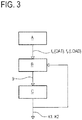
- control unit is configured for carrying out the following steps (which may also be steps of a method for assessing the performance of the chiller 1):
- the step of measuring B provides a dataset of actual values of the diagnostic parameters; then, in the step of calculating C, the control unit adjusts the initialized input space on the basis of the actual values, to provide the mapping 10.
- the mapping 10 is more precise in the points which are nearer to the points wherein the values of the diagnostic parameters 9 are measured; in fact, in the points which are farer from the actual values of the diagnostic parameters 9, the diagnostic parameter is more approximately estimated (by means of interpolations and/or extrapolations).
- Steps B and C may be periodically repeated, to update the mapping 10, so as to assess the performance over time. So, the control unit may assess a performance trend over time.
- the control unit may, at a plurality of predefined time instants (e.g. every month), perform measurements of the diagnostic parameter 9 at respective couples of values of the first and second input parameter 7, 8; then, the control unit may memorize, for each measurement, a record including the measured value of the diagnostic parameter 9, the couple of values of the first and second input parameter 7, 8 at which the diagnostic parameter 9 has been measured, and a timestamp representative of the time instant at which the measurement has been carried out.
- the record may be memorized in the local memory or the control unit and/or may be sent to a remote server in which records originated by a plurality of chillers 1 are collected.
- the diagnostic parameter 9 may be measured continuously over time (and, also, the first and second input parameter 7, 8 are measured continuously) and that the control unit may include a respective threshold value for the first and/or second input parameter 7, 8.
- the control unit may activate the memorization of a record including the measured diagnostic parameter 9 and the first and second input parameter 7, 8 at which it is measured (preferably, together with a timestamp representative of the time instant at which the measurement has been carried out).
- This record may be memorized in the local memory or the control unit and/or may be sent to a remote server in which records originated by a plurality of chillers 1 are collected.
- the chiller 1 is deliberately run at a predefined range of values of the first input parameter (namely, load), in order to obtain a plurality of diagnostic parameters 9 measured in the whole predefined range of values of the first input parameter.
- the predefined range of values may be, for instance, from 25% to 100% of the maximum load.
Abstract
Description
- The present invention relates to a method and a system for providing a diagnostic assessment of a chiller.
- Chillers commonly comprise a refrigeration circuit for circulating a refrigerant fluid, the refrigeration circuit includes a compressor, a condenser, an evaporator, an expansion valve. Examples of chillers are provided in patent documents
EP2333438A1 andEP2306101A1 of the same patentee. - Chillers are characterized by a certain performance, which may be defined by parameters such as Energy Efficiency Ratio (EER), Coefficient of Performance (COP), or others. These parameters change over the life of the chiller; in particular, they have a certain value when the chiller is new and may decrease when the chiller gets old. Hence, there is a need to observe the trend of the chiller performance over time, to evaluate, for example, when the chiller has to be substituted.
- Methods for evaluating performance of chillers are disclosed in the following patent documents:
EP2420759A1 ,US2011/283718A1 ,EP2660537A1 ,JP2005114295A US2018/010835A1 ,EP2908066A2 . In this context, there is a need to evaluate the performance with increased effectiveness and precision. - Scope of the present invention is to provide method and a system which overcome the aforementioned drawbacks.
- This scope is achieved by the method and the system for providing a diagnostic assessment of a chiller, according to one or more of the appended claims.
- The present disclosure relates to a method for providing a diagnostic assessment of a chiller (or refrigeration system).
- The chiller includes one or more refrigeration circuits. The chiller (or each of said one or more refrigeration circuits) comprises a refrigerant fluid. The chiller (or each of said one or more refrigeration circuits) is configured for circulating the refrigerant fluid.
- The chiller (or each of said one or more refrigeration circuits) includes a condenser. The condenser is configured for condensing the refrigerant fluid. The condenser is configured for providing heat exchange between the refrigerant fluid and an external fluid (for example external air or water). In particular, in the condenser the refrigerant fluid releases heat to said external fluid, resulting in condensation of the refrigerant fluid.
- The chiller (or each of said one or more refrigeration circuits) includes an expansion valve. The expansion valve is configured for expanding the refrigerant fluid. More generically, the expansion valve may be substituted by an expansion device.
- The chiller (or each of said one or more refrigeration circuits) includes an evaporator. The evaporator is configured for providing heat exchange between the refrigerant fluid and a fluid to be cooled (for example, room air to be cooled or water to be cooled). In particular, in the evaporator, the refrigerant fluid absorbs heat from said fluid to be cooled, resulting in evaporation of the refrigerant fluid.
- The chiller (or each of said one or more refrigeration circuits) includes a compressor. The compressor is configured for compressing the refrigerant fluid. The compressor includes a motor (e.g. an electric motor).
- It is here observed that the compressor, the evaporator, the condenser and the expansion valve of each of said one or more refrigeration circuits of the chiller defines a component of the chiller. Hence, the chiller is provided with a plurality of components, including at least a compressor, a condenser, an evaporator and an expansion valve. In particular, the chiller includes a compressor, a condenser, an evaporator and an expansion valve for each of said one or more refrigeration circuits.
- The method comprises a step of providing a diagnostic parameter, representative of the performance of the chiller or of one of its components (e.g. of one compressor). In particular, the diagnostic parameter may be provided by measuring it or by estimating (calculating) it on the basis of measurements.
- The method comprises a step of providing a first input parameter. The first input parameter is representative of a working condition of the chiller or of one of its components.
- The method comprises a step of providing a second input parameter. The second input parameter is representative of a working condition of the chiller (or of one of its components). In fact, the performance of the chiller (or of one of its components) depends on the working conditions and has to be evaluated on the basis of these working conditions.
- The method comprises a step of memorizing a plurality of values for the diagnostic parameter, each value being measured (or calculated starting from corresponding measurements) at a respective value of the first and/or second input parameter. In particular, each value is measured (or calculated starting from corresponding measurements) at a respective couple of values of the first and second input parameter.
- The method comprises a step of providing a mapping of the diagnostic parameter in an input space defined by the first and/or second input parameters; in particular, the mapping of the diagnostic parameter is such that each couple of values of the first and second input parameter defines a corresponding point in the input space (the point corresponding to a value of the diagnostic parameter).
- The method comprises a step of assessing the performance of the chiller (or of one of its components) based on the mapping of the diagnostic parameter.
- In particular, the first input parameter is the load of the chiller (or of one of its components) (with respect to a maximum load value, or as an absolute value). For example, the (actual) load of the chiller (or of one of its components) may have a value comprised between 25% and 100% of the maximum load value. The load may be assessed on the basis of the power consumption of the compressor (for instance, a power sensor may be provided to measure the power absorbed by the compressor).
- It is provided that the second input parameter is the temperature of the external fluid (in heat exchange with the refrigerant fluid in the condenser). In particular, in case the condenser is configured to provide heat exchange between the refrigerant fluid and external (ambient) air, the second input parameter is (the value of) the external air temperature. For example, the external air may have a value comprised between 5°C and 45°C. The external air temperature may be measured by a thermometer provided in the external environment. In case the condenser is configured to provide heat exchange between the refrigerant fluid and water, the second input parameter is (the value of) the temperature of the water at the outlet of the condenser. The water temperature may be measured by a thermometer provided in the water circuit at the outlet of the condenser.
- Preferably, the plurality of values for the diagnostic parameter includes two or more values measured at different load values and two or more values measured at different values of the second input parameter.
- Preferably, the step of assessing the performance of the chiller (or of one of its components) based on the mapping of the diagnostic parameter includes calculating a weighted average of the diagnostic parameter over a plurality of points of the input space having different values of the load. Preferably, the method comprises a step of deriving (or estimating) further values for the diagnostic parameter at corresponding further points of the input space, on the basis of the measured values for the diagnostic parameter.
- Preferably, the further values for the diagnostic parameter are derived (or estimated) as a function of a distance, evaluated in the input space, of the further points with respect to the measured points. In particular, said further values may be derived through extrapolation and/or interpolation. So, the diagnostic parameter may be provided over the whole input space. In an ideal solution, it would be recommended to calculate the value of the diagnostic parameter over the whole input space, namely at all the possible load values and at all the possible values of the second input parameter. However, this would require that the chiller is placed at all the possible working conditions in a reasonably short amount of time (because of the performance changes over time, a diagnostic parameter value may not be significant of the performance of the chiller (or of one of its components) at a certain time instant, if it is measured several months after the time instant). This is quite difficult to obtain, since, for example, the external temperature changes with seasons: hence, if the diagnostic parameter is measured during winter, the points of the input space corresponding to high external air temperature can hardly be reached. For these reasons, it is preferably provided the step of deriving further values for the diagnostic parameter at corresponding further points of the input space.
- In an embodiment, the method comprises a step of measuring (or calculating on the basis of measurements) additional values of the diagnostic parameter at successive times, and a step of upgrading the mapping over time, on the basis of the additional values. Therefore, the diagnostic parameter values in the input space may be calculated at different time instants over the life of the chiller. In particular, the upgrading of the mapping may be carried out through artificial intelligence techniques. In an embodiment, the performance of the chiller is evaluated as a function of a variation of the mapping over time. Also, the variation of the mapping over time may be evaluated by artificial intelligence techniques.
- The diagnostic parameter is preferably selected from the following list (or representative of a parameter of the following list):
- Energy efficiency ratio (EER);
- Coefficient of performance (COP);
- Compressor Isoentropic Efficiency;
- Evaporator Logarithmic Mean Temperature Difference;
- Condenser Logarithmic Mean Temperature Difference;
- Rate of opening of the expansion valve;
- Evaporator heat exchange coefficient;
- Condenser heat exchange coefficient.
- In case the chiller comprises a plurality of refrigeration circuits, each one including a respective evaporator, a respective condenser, a respective expansion valve and a respective compressor, the above-mentioned parameters may be referred to a certain refrigeration circuit of said plurality, or may be mean values of the said plurality of refrigeration circuits (or of a certain sub-set of said plurality of refrigeration circuits).
- In particular, the EER or COP is the ratio of the output cooling or heating power (e.g. measured in kW) to the input electrical power (e.g. measured in kW), required to provide said cooling or heating power.
- The Compressor isoentropic efficiency is the ratio of the delta enthalpy (expressed in kJ/kg) required to execute an ideal compression process (e.g. without any variation on entropy) to the delta enthalpy actually required by the real compression process, wherein the delta enthalpy actually required may be calculated as a function of the ratio between the electrical power at the compressor inlet (expressed in kW, i.e. kJ/s) to the compressor mass flow rate (expressed in kg/s).
- The Logarithmic Mean Temperature Difference of the evaporator and of the condenser is defined as follows:

- The rate of opening of the expansion valve is an aperture degree of the expansion valve.
- The heat exchange coefficient (or heat transfer coefficient) of the evaporator or of the condenser is ratio of the exchanged heat in the evaporator or condenser (in watts) to the product between the useful area of heat exchange (in m2) and the Logarithmic Mean Temperature Difference of the evaporator and of the condenser, respectively (in Kelvin). The present disclosure also provides a system for providing a diagnostic assessment of a chiller. The chiller includes (or is provided with) a plurality of components, including compressor, a condenser, an evaporator, an expansion valve and a refrigerant fluid.
- The system comprises a (or at least one) sensor for sensing a diagnostic parameter, representative of the performance of the chiller (or of one of its components) (or for sensing values which allow to calculate the diagnostic parameter).
- The system comprises a control unit. In an embodiment, the control unit calculates the diagnostic parameter on the basis of sensed values).
- The control unit includes a processor. Preferably, the control unit includes a memory (or is connected to a remote memory). The control unit is configured for receiving values of a first input parameter and/or of a second input parameter; the first and the second input parameter are representative of a working condition of the chiller (or of one of its components).
- The control unit (in detail, the processor) is programmed for measuring (receiving or calculating), through the sensor (or the at least one sensor), a plurality of values for the diagnostic parameter. Each value of said plurality is measured at a respective couple of values of the first and second input parameter.
- The control unit (in detail, the processor) is programmed for storing the plurality of measured value in the memory, thus providing a mapping of the diagnostic parameter in an input space defined by the first and second input parameters, so that each couple of values of the first and second input parameter defines a corresponding point in the input space (wherein the diagnostic parameter has a certain value).
- The control unit (in detail, the processor) is programmed for assessing the performance of the chiller (or of one of its components), based on the mapping of the diagnostic parameter.
- Preferably, the first input parameter is the load of the chiller (or of one of its components), with respect to a maximum load value.
- Preferably, the second input parameter is the temperature of an external fluid at the inlet or at the outlet of the condenser, wherein the condenser is configured to provide heat exchange between the refrigerant fluid and the external fluid. In particular, the second input parameter may be the temperature of the external air or the temperature of the water (the external fluid being water) at the outlet of the condenser.
- The diagnostic parameter is selected from the following list (or is representative of a parameter of the following list):
- Energy efficiency ratio (EER);
- Coefficient of performance (COP);
- Compressor Isoentropic Efficiency;
- Evaporator Logarithmic Mean Temperature Difference;
- Condenser Logarithmic Mean Temperature Difference;
- Rate of opening of the expansion valve;
- Evaporator heat exchange coefficient;
- Condenser heat exchange coefficient.
- It is also provided a system wherein a plurality of diagnostic parameters selected from said list are assessed.
- In particular, if the diagnostic parameter is the EER or COP. A sensor or a plurality of sensors will be provided to sense the cooling or heating power and an additional sensor or a plurality of sensors will be provided to sense the chiller input electrical power.
- If the diagnostic parameter is the Isoentropic Efficiency, a sensor or a plurality of sensors will be provided to sense the compressor mass flow rate and an additional sensor or a plurality of sensors will be provided to sense electrical power at the compressor inlet (which are used to calculate the enthalpy at compressor inlet/outlet).
- If the diagnostic parameter is the Evaporator Logarithmic Mean Temperature Difference, a sensor or a plurality of sensors will be provided at the evaporator, to sense a refrigerant saturated temperature at the evaporator.
- If the diagnostic parameter is the Condenser Logarithmic Mean Temperature Difference, a sensor or a plurality of sensors will be provided at the condenser, to sense a refrigerant saturated temperature at the condenser.
- If the diagnostic parameter is the rate of opening of the expansion valve, a sensor or a plurality of sensors will be provided at the expansion valve, to sense said rate of opening of the expansion valve.
- If the diagnostic parameter is the evaporator heat exchange coefficient, a sensor or a plurality of sensors will be provided at the evaporator, to sense the refrigerant saturated temperature, and an additional sensor will be provided at the evaporator, to sense the water inlet and/or outlet temperature.
- If the diagnostic parameter is the condenser heat exchange coefficient, a sensor or a plurality of sensors will be provided at the condenser, to sense the refrigerant saturated temperature, and an additional sensor or a plurality of sensors will be provided at the condenser, to sense the water inlet and/or outlet temperature at condenser.
- Preferably, the processor is programmed for deriving further values for the diagnostic parameter at corresponding further points of the input space, on the basis of the measured values for the diagnostic parameter. For example, further values may be derived through extrapolation and/or interpolation.
- Preferably, the processor is programmed for measuring additional values of the diagnostic parameter at successive times, and for upgrading the mapping over time, on the basis of the additional values.
- In an embodiment, the control unit is located in a server remote from the chiller and is connected, through a communication network, to a plurality of sensors located at a corresponding plurality of chillers, for assessing the performance of each chiller (or of a component of each chiller) of said plurality of chillers. In particular, the control unit includes a database which receives a plurality of diagnostic parameters from the plurality of chillers (during successive time instants) and performs overall evaluations to assess an average performance trend of the plurality of chillers. In an embodiment, the control unit is configured for comparing a first diagnostic parameter measured on a first chiller of said plurality with a second diagnostic parameter measured on a second chiller of said plurality, and to evaluate the performance of the first chiller with respect to the performance of the second chiller. In an embodiment, the control unit is configured for comparing a first mapping derived for the first chiller with a second mapping derived for the second chiller, to evaluate the performance of the first chiller with respect to the performance of the second chiller.
- It is here observed that the present disclosure may also regard a remote server connected to a plurality of chillers and programmed to receive a plurality of measured diagnostic parameters from the plurality of chillers and to perform aggregated performance analysis of the chillers (or of components thereof), based on the corresponding plurality of measured diagnostic parameters.
- The present disclosure also relates to a chiller comprising (at least) a refrigerant circuit including compressor, a condenser, an evaporator and an expansion valve, and a refrigerant fluid circulating in the refrigerant circuit. The chiller comprises a system for providing a diagnostic assessment of the chiller, the system being according to one or more of the aspects of the present disclosure.
- The present disclosure also relates to a computer program, including instructions for carrying out the steps of the method according to one or more of the aspects of the present disclosure, in particular when run in the system according to one or more of the aspects of the present disclosure. This and other features of the invention will become more apparent from the following detailed description of a preferred, non-limiting example embodiment of it, with reference to the accompanying drawings, in which:
-
Figure 1 schematically illustrates a chiller according to the present description; -
Figure 2 schematically illustrates a mapping including a plurality of values of the diagnostic parameter calculated or estimated for the chiller offigure 1 ; -
Figure 3 schematically illustrates steps of a method for providing the mapping offigure 2 . - With reference to the accompanying drawings, the
numeral 1 denotes a chiller. Thechiller 1 comprises a refrigeration circuit. The refrigeration circuit (or the chiller) includes a plurality of components, including acompressor 2, a condenser 3, anevaporator 4 and anexpansion valve 5. In non-illustrated embodiments, thechiller 1 may comprise a plurality of refrigeration circuits. - In an embodiment, the chiller 1 (or the refrigeration circuit) comprises a four-
way valve 6, configured to allow thechiller 1 to work both in a refrigeration mode and in a cooling mode. - The
chiller 1 comprises a system for providing a diagnostic assessment of the chiller 1 (or of a component of the chiller 1). - The system includes a diagnostic sensor for sensing a diagnostic parameter 9 (or for sensing parameters representative thereof).
- Furthermore, the system includes a first sensor, configured for sensing a
first input parameter 7, which is preferably the load of the chiller 1 (in particular, of the compressor 2). The system includes a second sensor, configured for sensing afirst input parameter 7, which is preferably the external (ambient) air temperature TOA. - The system includes a control unit. The control unit is programmed for receiving a plurality of values of the
diagnostic parameter 9, each value of thediagnostic parameter 9 being detected at a respective couple of values of the first andsecond input parameter - The control unit is further programmed for storing the plurality of measured values of the
diagnostic parameter 9 in a memory, thus providing amapping 10 of thediagnostic parameter 9 in an input space defined by the first andsecond input parameters second input parameter diagnostic parameter 9 takes a certain value. - In particular, the control unit is configured for carrying out the following steps (which may also be steps of a method for assessing the performance of the chiller 1):
- A) Receiving an initialized input space, wherein in the initialized input space the
diagnostic value 9 is provided as a function of the load and as a function of the external air temperature TOA (or of the water at the outlet of the condenser); in particular, in the initialized input space, initial values of the diagnostic parameter 9 (e.g. the EER) may be expressed as follows:
- B) Measuring, through the sensor, a plurality of values for the
diagnostic parameter 9, each value being measured at a respective couple of values of the first andsecond input parameter diagnostic parameters 9 in the memory; - C) Calculating coefficients of proximity k1 and k2 on the basis of the initialized input space and of the measured values of the
diagnostic parameter 9, so that the diagnostic parameter may be provided by the following formula: EER= k1 ∗f1(OAT) + k2 ∗f2(LOAD). - Hence, the step of measuring B provides a dataset of actual values of the diagnostic parameters; then, in the step of calculating C, the control unit adjusts the initialized input space on the basis of the actual values, to provide the
mapping 10. Of course, themapping 10 is more precise in the points which are nearer to the points wherein the values of thediagnostic parameters 9 are measured; in fact, in the points which are farer from the actual values of thediagnostic parameters 9, the diagnostic parameter is more approximately estimated (by means of interpolations and/or extrapolations). - Steps B and C may be periodically repeated, to update the
mapping 10, so as to assess the performance over time. So, the control unit may assess a performance trend over time. - In particular, with regard to step B of measuring, it is observed the following. The control unit may, at a plurality of predefined time instants (e.g. every month), perform measurements of the
diagnostic parameter 9 at respective couples of values of the first andsecond input parameter diagnostic parameter 9, the couple of values of the first andsecond input parameter diagnostic parameter 9 has been measured, and a timestamp representative of the time instant at which the measurement has been carried out. The record may be memorized in the local memory or the control unit and/or may be sent to a remote server in which records originated by a plurality ofchillers 1 are collected. - It is also provided that the
diagnostic parameter 9 may be measured continuously over time (and, also, the first andsecond input parameter second input parameter second input parameter diagnostic parameter 9 and the first andsecond input parameter chillers 1 are collected. - It is also provided that, in the measuring step B, the
chiller 1 is deliberately run at a predefined range of values of the first input parameter (namely, load), in order to obtain a plurality ofdiagnostic parameters 9 measured in the whole predefined range of values of the first input parameter. The predefined range of values may be, for instance, from 25% to 100% of the maximum load.
Claims (15)
- A method for providing a diagnostic assessment of a chiller (1), the chiller (1) being provided with a refrigerant fluid and a plurality of components including a compressor (2), a condenser (3), an evaporator (4), an expansion valve (5), the method comprising the following steps:• providing a diagnostic parameter (9), representative of a performance of the chiller (1) or of one of its components;• providing a first input parameter (7) and a second input parameter (8), the first and the second input parameter (7, 8) being representative of a working condition of the chiller (1) or of one of its components;• memorizing a plurality of values for the diagnostic parameter (9), each value being measured at a respective couple of values of the first and second input parameter (7, 8), whereby providing a mapping (10) of the diagnostic parameter (9) in an input space defined by the first and second input parameters (7, 8), so that each couple of values of the first and second input parameter (7, 8) defines a corresponding point in the input space (10);• assessing the performance of the chiller (1) or of one of its components, based on the mapping (10) of the diagnostic parameter (9).
- The method of claim 1, wherein the first input parameter (7) is the load of the chiller (1) or of one of its components, with respect to a maximum load value, wherein the condenser (3) is configured to provide heat exchange between the refrigerant fluid and an external fluid and wherein the second input parameter (8) is the temperature of the external fluid at the inlet or at the outlet of the condenser (3).
- The method of claim 2, wherein the plurality of values for the diagnostic parameter (9) includes two or more values measured at different load values and two or more values measured at different values of the second input parameter (8).
- The method of any of the previous claims, wherein assessing the performance of the chiller (1) or of one of its components, based on the mapping (10) of the diagnostic parameter (9), includes calculating a weighted average of the diagnostic parameter (9) over a plurality of points of the input space (10) having different values of the load.
- The method of any of the previous claims, comprising a step of deriving further values for the diagnostic parameter (9) at corresponding further points of the input space (10), on the basis of the measured values for the diagnostic parameter (9), wherein the further values for the diagnostic parameter (9) are derived as a function of a distance, evaluated in the input space, of the further points with respect to the points wherein the value of the diagnostic parameter (9) is measured.
- The method of any of the previous claims, comprising a step of measuring additional values of the diagnostic parameter (9) at successive times, and a step of upgrading the mapping (10) over time, on the basis of the additional values.
- The method of claim 6, wherein the upgrading of the mapping (10) is carried out through artificial intelligence techniques.
- The method of claim 6 or 7, wherein the performance of the chiller (1) is assessed as a function of a variation of the mapping (10) over time.
- The method of any of the previous claims, wherein the diagnostic parameter (9) is selected from the following list:• Energy efficiency ratio;• Coefficient of performance;• Evaporator Logarithmic Mean Temperature Difference;• Condenser Logarithmic Mean Temperature Difference;• Rate of opening of the expansion valve;• Evaporator heat exchange coefficient;• Condenser heat exchange coefficient.
- A system for providing a diagnostic assessment of a chiller (1), the chiller (1) being provided with a refrigerant fluid and a plurality of components including a compressor (2), a condenser (3), an evaporator (4), an expansion valve (5), wherein the system comprises:• a sensor or a plurality of sensors for providing a diagnostic parameter (9), representative of a performance of the chiller (1) or of one of its components;• a control unit, including a memory and a processor, and configured for receiving values of a first input parameter (7) and of a second input parameter (8), the first and the second input parameter (7, 8) being representative of a working condition of the chiller (1) or of one of its components,wherein the processor is programmed for measuring, through the sensor, a plurality of values for the diagnostic parameter (9), each value being measured at a respective couple of values of the first and second input parameter (7, 8), and for storing the plurality of measured value in the memory, thus providing a mapping (10) of the diagnostic parameter (9) in an input space defined by the first and second input parameters (7, 8), so that each couple of values of the first and second input parameter (7, 8) defines a corresponding point in the input space, the processor being further programmed for assessing the performance of the chiller (1) or of one of its components, based on the mapping of the diagnostic parameter (9).
- The system of claim 10, wherein the processor is programmed for measuring additional values of the diagnostic parameter (9) at successive times, and for upgrading the mapping (10) over time, on the basis of the additional values.
- The system of claim 10 or 11, wherein the control unit is located in a server remote from the chiller (1) and is connected, through a communication network, to a plurality of sensors located at a corresponding plurality of chillers (1), for assessing the performance of each chiller (1), or of one of the components of each chiller (1), among said plurality of chillers (1).
- The system of claim 12, wherein the control unit is configured for comparing a first diagnostic parameter (9) measured on a first chiller (1) of said plurality of chillers with a second diagnostic parameter (9) measured on a second chiller (1) of said plurality of chillers (1), and/or for comparing a first mapping (10) derived for the first chiller (1) of said plurality of chillers (1) with a second mapping (10) derived for the second chiller (1) of said plurality of chillers (1), to assess the performance of the first chiller (1) with respect to the performance of the second chiller (1).
- A chiller (1) comprising a refrigerant circuit including compressor (2), a condenser (3), an evaporator (4) and an expansion valve (5), and a refrigerant fluid circulating in the refrigerant circuit, wherein the chiller (1) comprises a system for providing a diagnostic assessment of a chiller (1), the system being according to any of the previous claims from 10 to 13.
- A computer program, including instructions for carrying out the steps of the method of any of the previous claims from 1 to 9, when run in the system of any of the previous claims from 10 to 14.
Applications Claiming Priority (1)
| Application Number | Priority Date | Filing Date | Title |
|---|---|---|---|
| IT102019000024138A IT201900024138A1 (en) | 2019-12-16 | 2019-12-16 | METHOD FOR CARRYING OUT A DIAGNOSTIC EVALUATION OF A CHILLER |
Publications (1)
| Publication Number | Publication Date |
|---|---|
| EP3839363A1 true EP3839363A1 (en) | 2021-06-23 |
Family
ID=69904108
Family Applications (1)
| Application Number | Title | Priority Date | Filing Date |
|---|---|---|---|
| EP20214011.7A Pending EP3839363A1 (en) | 2019-12-16 | 2020-12-15 | A method for providing a diagnostic assessment of a chiller |
Country Status (2)
| Country | Link |
|---|---|
| EP (1) | EP3839363A1 (en) |
| IT (1) | IT201900024138A1 (en) |
Citations (8)
| Publication number | Priority date | Publication date | Assignee | Title |
|---|---|---|---|---|
| JP2005114295A (en) | 2003-10-09 | 2005-04-28 | Takasago Thermal Eng Co Ltd | Heat source system and controller |
| EP2306101A1 (en) | 2008-06-12 | 2011-04-06 | Daikin Industries, Ltd. | Air conditioner |
| EP2333438A1 (en) | 2008-09-17 | 2011-06-15 | Daikin Industries, Ltd. | Air conditioning device |
| US20110283718A1 (en) | 2009-03-30 | 2011-11-24 | Mitsubishi Heavy Industries, Ltd. | Heat-source system and method for controlling the same |
| EP2420759A2 (en) | 2010-07-29 | 2012-02-22 | Mitsubishi Heavy Industries, Ltd. | Centrifugal chiller performance evaluation system |
| EP2660537A1 (en) | 2010-12-28 | 2013-11-06 | Mitsubishi Heavy Industries, Ltd. | Heat source system and control method therefor |
| EP2908066A2 (en) | 2013-12-18 | 2015-08-19 | Mitsubishi Heavy Industries, Ltd. | Evaluation supporting apparatus, method, and program for air conditioning system |
| US20180010835A1 (en) | 2016-07-07 | 2018-01-11 | Rocky Research | Vector drive for vapor compression systems |
-
2019
- 2019-12-16 IT IT102019000024138A patent/IT201900024138A1/en unknown
-
2020
- 2020-12-15 EP EP20214011.7A patent/EP3839363A1/en active Pending
Patent Citations (8)
| Publication number | Priority date | Publication date | Assignee | Title |
|---|---|---|---|---|
| JP2005114295A (en) | 2003-10-09 | 2005-04-28 | Takasago Thermal Eng Co Ltd | Heat source system and controller |
| EP2306101A1 (en) | 2008-06-12 | 2011-04-06 | Daikin Industries, Ltd. | Air conditioner |
| EP2333438A1 (en) | 2008-09-17 | 2011-06-15 | Daikin Industries, Ltd. | Air conditioning device |
| US20110283718A1 (en) | 2009-03-30 | 2011-11-24 | Mitsubishi Heavy Industries, Ltd. | Heat-source system and method for controlling the same |
| EP2420759A2 (en) | 2010-07-29 | 2012-02-22 | Mitsubishi Heavy Industries, Ltd. | Centrifugal chiller performance evaluation system |
| EP2660537A1 (en) | 2010-12-28 | 2013-11-06 | Mitsubishi Heavy Industries, Ltd. | Heat source system and control method therefor |
| EP2908066A2 (en) | 2013-12-18 | 2015-08-19 | Mitsubishi Heavy Industries, Ltd. | Evaluation supporting apparatus, method, and program for air conditioning system |
| US20180010835A1 (en) | 2016-07-07 | 2018-01-11 | Rocky Research | Vector drive for vapor compression systems |
Also Published As
| Publication number | Publication date |
|---|---|
| IT201900024138A1 (en) | 2021-06-16 |
Similar Documents
| Publication | Publication Date | Title |
|---|---|---|
| US9435576B1 (en) | Cost-effective remote monitoring diagnostic and system health prediction system and method for vapor compression and heat pump units based on compressor discharge line temperature sampling | |
| US7631508B2 (en) | Apparatus and method for determining refrigerant charge level | |
| Kim et al. | Design of a steady-state detector for fault detection and diagnosis of a residential air conditioner | |
| Li et al. | Decoupling features and virtual sensors for diagnosis of faults in vapor compression air conditioners | |
| US7188482B2 (en) | Fault diagnostics and prognostics based on distance fault classifiers | |
| Li et al. | Development, evaluation, and demonstration of a virtual refrigerant charge sensor | |
| JP6359423B2 (en) | Control device for air conditioning system, air conditioning system, and abnormality determination method for control device for air conditioning system | |
| Grace et al. | Sensitivity of refrigeration system performance to charge levels and parameters for on-line leak detection | |
| US20080066474A1 (en) | Refrigeration system energy efficiency enhancement using microsystems | |
| Kim et al. | Extension of a virtual refrigerant charge sensor | |
| Kim et al. | Fault detection and diagnostics analysis of air conditioners using virtual sensors | |
| JP3746729B2 (en) | How to detect equipment degradation | |
| Naik et al. | Empirical correlation based models for estimation of air cooled and water cooled condenser's performance | |
| JP2010025475A (en) | Failure diagnostic device used for refrigerating cycle equipment | |
| Cheung et al. | A general method for calculating the uncertainty of virtual sensors for packaged air conditioners | |
| JP6750091B2 (en) | Air conditioner performance diagnostic device and performance diagnostic method | |
| CA2984998A1 (en) | System and method for charging a refrigeration system | |
| JP6972468B2 (en) | Evaluation device and evaluation method for air conditioners | |
| Cheung et al. | Minimizing data collection for field calibration of steady-state virtual sensors for HVAC equipment | |
| EP3839363A1 (en) | A method for providing a diagnostic assessment of a chiller | |
| Liu et al. | A hierarchical gray-box dynamic modeling methodology for direct-expansion cooling systems to support control stability analysis | |
| Patil et al. | Development and Evaluation of an Automated Virtual Refrigerant Charge Sensor Training Kit | |
| KR100466433B1 (en) | Method for analysis of efficiency in turbo refrigerator and apparatus thereof | |
| Ng et al. | The role of internal dissipation and process average temperature in chiller performance and diagnostics | |
| WO2022085691A1 (en) | Air conditioner |
Legal Events
| Date | Code | Title | Description |
|---|---|---|---|
| PUAI | Public reference made under article 153(3) epc to a published international application that has entered the european phase |
Free format text: ORIGINAL CODE: 0009012 |
|
| STAA | Information on the status of an ep patent application or granted ep patent |
Free format text: STATUS: THE APPLICATION HAS BEEN PUBLISHED |
|
| AK | Designated contracting states |
Kind code of ref document: A1 Designated state(s): AL AT BE BG CH CY CZ DE DK EE ES FI FR GB GR HR HU IE IS IT LI LT LU LV MC MK MT NL NO PL PT RO RS SE SI SK SM TR |
|
| STAA | Information on the status of an ep patent application or granted ep patent |
Free format text: STATUS: REQUEST FOR EXAMINATION WAS MADE |
|
| 17P | Request for examination filed |
Effective date: 20211221 |
|
| RBV | Designated contracting states (corrected) |
Designated state(s): AL AT BE BG CH CY CZ DE DK EE ES FI FR GB GR HR HU IE IS IT LI LT LU LV MC MK MT NL NO PL PT RO RS SE SI SK SM TR |
|
| STAA | Information on the status of an ep patent application or granted ep patent |
Free format text: STATUS: EXAMINATION IS IN PROGRESS |
|
| 17Q | First examination report despatched |
Effective date: 20230731 |