EP3839352B1 - Thermoelektrische anordnung zur speisung einer vielzahl von elektromagnetischen ventilen eines kochgerätes - Google Patents
Thermoelektrische anordnung zur speisung einer vielzahl von elektromagnetischen ventilen eines kochgerätes Download PDFInfo
- Publication number
- EP3839352B1 EP3839352B1 EP19383142.7A EP19383142A EP3839352B1 EP 3839352 B1 EP3839352 B1 EP 3839352B1 EP 19383142 A EP19383142 A EP 19383142A EP 3839352 B1 EP3839352 B1 EP 3839352B1
- Authority
- EP
- European Patent Office
- Prior art keywords
- transistor
- current circuit
- thermoelectric assembly
- power supply
- assembly according
- Prior art date
- Legal status (The legal status is an assumption and is not a legal conclusion. Google has not performed a legal analysis and makes no representation as to the accuracy of the status listed.)
- Active
Links
Images


Classifications
-
- F—MECHANICAL ENGINEERING; LIGHTING; HEATING; WEAPONS; BLASTING
- F23—COMBUSTION APPARATUS; COMBUSTION PROCESSES
- F23N—REGULATING OR CONTROLLING COMBUSTION
- F23N5/00—Systems for controlling combustion
- F23N5/02—Systems for controlling combustion using devices responsive to thermal changes or to thermal expansion of a medium
- F23N5/10—Systems for controlling combustion using devices responsive to thermal changes or to thermal expansion of a medium using thermocouples
- F23N5/102—Systems for controlling combustion using devices responsive to thermal changes or to thermal expansion of a medium using thermocouples using electronic means
-
- F—MECHANICAL ENGINEERING; LIGHTING; HEATING; WEAPONS; BLASTING
- F24—HEATING; RANGES; VENTILATING
- F24C—DOMESTIC STOVES OR RANGES ; DETAILS OF DOMESTIC STOVES OR RANGES, OF GENERAL APPLICATION
- F24C3/00—Stoves or ranges for gaseous fuels
- F24C3/12—Arrangement or mounting of control or safety devices
- F24C3/126—Arrangement or mounting of control or safety devices on ranges
Definitions
- the present invention relates to a thermoelectric assembly for powering a plurality of electromagnetic valves of a cooking appliance, each electromagnetic valve allowing or preventing the passage of gas to a respective burner of the cooking appliance.
- EP 0288390 A1 furthermore describes electric circuits in which a MOSFET is arranged between the thermocouple and the electromagnetic valve, said MOSFET acting like a switch, such that depending on pre-established parameters, the MOSFET can open the circuit preventing the passage of current to the electromagnetic valve, and therefore causing the electromagnetic valve to close the passage of gas to the burner regardless of the presence of flame in the corresponding burner.
- thermoelectric assembly comprises a main current circuit associated with a respective electromagnetic valve, the main current circuit comprising a thermocouple configured for detecting flame in the corresponding burner, a cable connected to the thermocouple and configured for electrically connecting said thermocouple with the corresponding electromagnetic valve, and a transistor connected to the cable and configured for de-energizing the electromagnetic valve.
- the main current circuit comprises a connection module comprising a power supply connected to the transistor, input terminals configured for being connected to an external energy source, a rectifier configured for transforming the alternating current of the external energy source into direct current, and a resistive block connected between one of the input terminals and the rectifier and configured for minimizing the current circulating through the power supply to a value that ensures a galvanic isolation.
- thermoelectric assembly having a main current circuit with a basic and simple power supply is thereby obtained, without having to include a transformer in said power supply for obtaining the required galvanic isolation.
- the power supply will thus be simpler and more cost-effective, and is therefore integrated in the main current circuit, particularly in the connection module together with the transistor.
- a main current circuit that is compact, simple, and can be readily connected to the external energy source is thereby obtained.
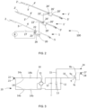
- FIG. 1 shows a thermoelectric assembly 100 according to the invention suitable for powering a plurality of electromagnetic valves 6 and 6' of a cooking appliance (not depicted in the drawings), each electromagnetic valve 6 and 6' being configured for closing the passage of gas to a corresponding burner (not depicted in the drawings) of the cooking appliance.
- the thermoelectric assembly 100 comprises a main current circuit 1 associated with a respective electromagnetic valve 6.
- the main current circuit 1 comprises a thermocouple 2 configured for detecting flame in the corresponding burner, cables 3 and 4 connected to the thermocouple 2 and configured for electrically connecting said thermocouple 2 with the corresponding electromagnetic valve 6 through a connector 5, a transistor 9 connected to one of the cables 3 and configured for de-energizing the electromagnetic valve 6, and a connection module 20 comprising a power supply 10 connected to the transistor 9.
- the transistor 9 is a field-effect transistor, preferably a MOSFET type transistor.
- the transistor 9 comprises a port terminal 9a, a drain terminal 9b, and a source terminal 9c, said transistor 9 being connected to the power supply 10 through the port terminal 9a and source terminal 9c.
- the transistor 9 behaves like a switch. In particular, when it operates in the cut-off region conduction between the source terminal 9c and the drain terminal 9b does not occur, so it operates like an open switch regardless of whether or not the thermocouple 2 detects the presence of flame, and therefore the electromagnetic valve is kept de-energized, preventing the passage of gas to the corresponding burner.
- the power supply 10 When the power supply 10 is connected to the external energy source 8, it powers the transistor 9 which operates like a closed switch, the electromagnetic valve is kept energized as long as the thermocouple 2 detects flame in the burner and a thermoelectric current capable of keeping the electromagnetic valve energized is generated.
- the transistor 9 has two connection terminals 27 and 28, each of which is connected to the cable 3 of the thermocouple 2.
- the power supply 10 comprises two input terminals 22 and 23 configured for being connected to the external energy source 8, a rectifier 11 configured for transforming the alternating current of the external energy source 8 into direct current, and a resistive block 14 connected between one of the input terminals 22 and 23 and the rectifier 11, the resistive block 14 being configured for minimizing the current circulating through the power supply 10 to a value equivalent to the galvanic isolation.
- the resistance of the resistive block 14 is about 2.24 megaohms.
- the power supply 10 comprises two resistive blocks 14, each of them connected to the corresponding input terminal 22 and 23.
- each resistive block 14 comprises at least two resistors 14a and 14b arranged such that they are connected in series.
- the resistance resulting from the two resistive blocks 14 is about 2.24 megaohms.
- the power supply 10 further comprises capacitance filters 12 connected in parallel to one another and in parallel to the rectifier 11, the capacitance filters 12 being configured for filtering or smoothing out ripple, resulting in a direct current whose voltage would virtually not vary over time.
- the power supply 10 further comprises a diode 13 connected in parallel to the rectifier 11 and to the capacitance filters 12.
- the rectifier 11 is a diode bridge.
- first input terminal 22 and the second input terminal 23 of the power supply 10 are configured for being connected with the external energy source 8, providing a form-fitting connection with the external energy source 8.
- This form-fitting connection is a simple and quick assembly/disassembly connection.
- the first input terminal 22 and the second input terminal 23 of the main current circuit 1 are configured for being connected, providing a male-female attachment.
- the power supply 10 and the transistor 9 are assembled on a PCB (not depicted) housed inside the body 21.
- the power supply 10 comprises an output terminal 24 projecting from the body 21.
- the input terminals 22 and 23 and the output terminal 24 project towards the outside orthogonal to the cover 26.
- connection module 20 of the main current circuit 1 may comprise an additional output terminal (not depicted) configured for connecting with a presence sensor for detecting the presence of utensils associated with the corresponding burner. Said additional output terminal will provide a form-fitting connection with the corresponding presence sensor.
- an electromechanical switch 25 is arranged between the power supply 10 and the power supply external 8.
- the switch 25 can be connected between the power supply 10 and the transistor 9.
- the connection module 20 houses the switch 27 in the body 21.
- the switch 27 is assembled on the PCB housed inside the body 21.
- the power supply 10 powers the transistor 9 such that the transistor 9 allows current to pass therethrough.
- the switch 27 closed, if the thermocouple 2 detects the presence of flame, it will generate a thermoelectric current that goes through the transistor 9 keeping the electromagnetic valve 6 such that it allows the passage of gas to the burner.
- the thermocouple 2 does not detect any flame, and therefore no longer generate the thermoelectric current required for keeping the electromagnetic valve 6 energized, said electromagnetic valve 6 closes the passage of gas.
- the transistor 9 When the corresponding signal is sent to the switch 27 from a non-depicted control so as to open said switch 27, the transistor 9 is not powered, so it acts like an open switch, not allowing current to go from the thermocouple 2 to the electromagnetic valve 6, the passage of gas is thereby closed.
- the transistor 9 therefore allows acting on the electromagnetic valve 6 de-energizing it when a previously defined parameter is achieved, said parameter not being the presence of flame in the burner 2.
- the thermoelectric assembly 100 further comprises at least one additional current circuit 1' associated with a respective electromagnetic valve 6', said additional current circuit 1' being able to be connected to the main current circuit 1.
- the thermoelectric assembly 100 comprises two additional current circuits 1', each of them associated with a respective electromagnetic valve 6'. Regardless of whether the thermoelectric assembly 100 includes one, two, or a plurality of additional current circuits, the features of each additional current circuit are similar and will be described below.
- Each additional current circuit 1' comprises a thermocouple 2' configured for detecting flame in the corresponding burner, cables 3' and 4' connected to the corresponding thermocouple 2' and configured for electrically connecting said thermocouple 2' with the corresponding electromagnetic valve 6' through a connector 5', and a transistor 9' connected to the corresponding cable 3' and configured for de-energizing the electromagnetic valve 6' to which it is connected.
- Each additional current circuit 1' comprises a connection module 20' housing the corresponding transistor 9', each connection module 20' comprising an input terminal 22' connected to the corresponding transistor 9'.
- the input terminal 22' is connected to the port 9a' of the respective transistor 9'.
- the connection module 20' of each additional current circuit 1' shown in Figures 2 and 4 , comprises an output terminal 24'.
- Each input terminal 22' of the corresponding additional current circuit 1' is configured for being connected to the output terminal 24 of the connection module 20 of the main current circuit 1 or to the output terminal 24' of another connection module 20' of the additional current circuit 1'.
- one of the additional current circuits 1' (hereinafter, first additional current circuit 1') is connected to the main current circuit 1 through respective connection modules 20 and 20'.
- the input terminal 22' of the connection module 20' of the first additional current circuit 1' is connected to the output terminal 24 of the main current circuit 1 as shown in Figure 2 .
- both additional current circuits 1' and 1" are connected to one another through respective connection modules 20'.
- the input terminal 22' of the connection module 20' of another additional current circuit 1" (hereinafter, second additional current circuit 1") is connected to the output terminal 24' of the connection module 20' of the first additional current circuit 1'.
- the output terminal 24 of the connection module 20 of the main current circuit 1 and the input terminal 22' of the connection module 20' of an additional current circuit 1' are configured for being connected, providing a form-fitting connection.
- This form-fitting connection is a simple and quick assembly/disassembly connection.
- the output terminal 24 of the connection module 20 of the main current circuit 1 and the input terminal 22' of the connection module 20' of the first additional current circuit 1' are configured for being connected, providing a male-female attachment.
- connection module 20' of each additional current circuit 1' comprises a body 21' inside which there is housed the respective transistor 9', with the input terminal 22' and the respective output terminal 24' projecting towards the outside of the respective body 21'.
- Each body 21' is made of an insulating material.
- Each body 21' comprises a corresponding cover 26' which closes the corresponding housing.
- the input terminal 22' and the output terminal 24' of the connection module 20' of the corresponding additional current circuit 1' project towards the outside orthogonal to the cover 26'.
- Each additional current circuit 1' further comprises a discharge resistor 15' of the transistor 9', said discharge resistor 15' being connected in parallel to the transistor 9' and configured for assuring the opening of the transistor 9' when said transistor 9' is no longer powered by the power supply 10.
- the discharge resistor 15' is arranged such that it is housed in the body 21' of the connection module 20'. In particular, the discharge resistor 15' is assembled on the PCB together with the transistor 9'.
- the output terminal 24' of the connection module 20' of the corresponding additional current circuit 1' is connected between the discharge resistor 15' of the additional current circuit 1' and the safety resistor 16' of the respective additional current circuit 1'.
- thermoelectric assembly 100 operates in the following manner, when the switch 25 is closed and the main current circuit 1 connected to the external energy source 8, the power supply 10 powers the transistors 9 and 9' of the main current circuit 1 and of the respective additional current circuits 1', said transistors 9 and 9' acting like closed switches allowing the thermoelectric current which is generated in the respective thermocouple 2 and 2' when there is flame in the corresponding burner to energize the respective electromagnetic valve 6 and 6'.
- the switch 25 opens such that the transistors 9 and 9' of the main current circuit 1 and of the additional current circuits 1' are not powered and act like open switches, the corresponding electromagnetic valve 6 and 6' being de-energized.
Landscapes
- Engineering & Computer Science (AREA)
- Chemical & Material Sciences (AREA)
- Combustion & Propulsion (AREA)
- Mechanical Engineering (AREA)
- General Engineering & Computer Science (AREA)
- Control Of Combustion (AREA)
Claims (15)
- Thermoelektrische Anordnung zur Speisung einer Vielzahl von elektromagnetischen Ventilen (6, 6') eines Kochgerätes, wobei jedes elektromagnetische Ventil (6, 6') dafür ausgebildet ist, den Durchgang von Gas zu einem entsprechenden Brenner des Kochgerätes zu schließen, wobei die thermoelektrische Anordnung (100) einen Hauptstromkreis (1) umfasst, welcher mit einem jeweiligen elektromagnetischen Ventil (6) assoziiert ist, wobei der Hauptstromkreis (1) ein Thermoelement (2), welches dafür ausgebildet ist, eine Flamme im entsprechenden zu detektieren, ein Kabel (3), welches mit dem Thermoelement (2) verbunden ist und dafür ausgebildet ist, das genannte Thermoelement (2) mit dem entsprechenden elektromagnetischen Ventil (6) elektrisch zu verbinden, einen Transistor (9), welcher mit dem Kabel (3) verbunden ist und dafür ausgebildet ist, das elektromagnetische Ventil (6) auszuschalten, und ein Verbindungsmodul (20), welches eine mit dem Transistor (9) verbundene Spannungsversorgung (10) umfasst, umfasst, wobei die Spannungsversorgung (10) Eingangsklemmen (22, 23), welche dafür ausgebildet sind, mit einer äußeren Energiequelle (8) verbunden zu werden, und einen Gleichrichter (11), welcher dafür ausgebildet ist, den Wechselstrom der äußeren Energiequelle (8) in Gleichstrom umzuwandeln, umfasst, dadurch gekennzeichnet, dass das Verbindungsmodul (20) zusätzlich einen Widerstandsblock (14), welcher zwischen einer der Eingangsklemmen (22, 23) der Spannungsversorgung (10) und dem Gleichrichter (11) verbunden ist, umfasst, wobei der Widerstandsblock (14) dafür ausgebildet ist, den Strom, welcher durch die Spannungsversorgung (10) zirkuliert, auf einen Wert zu minimieren, welcher eine galvanische Trennung gewährleistet, welche ansonsten von einem Wandler bereitgestellt worden wäre.
- Thermoelektrische Anordnung nach dem vorhergehenden Anspruch, wobei der Widerstandsblock (14) mindestens zwei Widerstandskörper (14a, 14b) umfasst, welche so angeordnet sind, dass sie in Serie geschaltet sind.
- Thermoelektrische Anordnung nach einem der vorhergehenden Ansprüche, wobei die Spannungsversorgung (10) zwei Widerstandsblöcke (14) umfasst, welche jeweils mit der entsprechenden Eingangsklemme (22, 23) verbunden sind.
- Thermoelektrische Anordnung nach Anspruch 1 oder 2, wobei der Widerstand des Widerstandsblocks (14) ungefähr 2,24 Megaohm ist.
- Thermoelektrische Anordnung nach Anspruch 3, wobei der Widerstand der beiden Widerstandsblöcke (14) ungefähr 2,24 Megaohm ist.
- Thermoelektrische Anordnung nach einem der vorhergehenden Ansprüche, wobei die erste Eingangsklemme (22) und die zweite Eingangsklemme (23) dafür ausgebildet sind, verbunden zu werden, unter Bereitstellung einer formschlüssigen Verbindung mit der äußeren Energiequelle (8).
- Thermoelektrische Anordnung nach einem der vorhergehenden Ansprüche, wobei das Verbindungsmodul (20) einen Körper (21) umfasst, innerhalb welches die Spannungsversorgung (10) und der Transistor (9) aufgenommen sind, mit den Eingangsklemmen (22, 23) und einer Ausgangsklemme (24) aus dem Körper (21) herausragend.
- Thermoelektrische Anordnung nach Anspruch 7, wobei das Verbindungsmodul (20) eine zusätzliche Ausgangsklemme umfasst, welche dafür ausgebildet ist, sich mit einem Anwesenheitssensor zu verbinden, um die Anwesenheit von mit dem entsprechenden Brenner assoziierten Utensilien zu detektieren.
- Thermoelektrische Anordnung nach Anspruch 7 oder 8, umfassend einen zusätzlichen Stromkreis (1'), welcher mit einem jeweiligen elektromagnetischen Ventil (6') assoziiert ist, wobei der zusätzliche Stromkreis (1') ein Thermoelement (2'), welches dafür ausgebildet ist, eine Flamme im entsprechenden Brenner zu detektieren, ein Kabel (3'), welches mit dem Thermoelement (2') verbunden ist und dafür ausgebildet ist, das genannte Thermoelement (2') mit dem entsprechenden elektromagnetischen Ventil (6') elektrisch zu verbinden, und einen Transistor (9'), welcher mit dem Kabel (3') verbunden ist und dafür ausgebildet ist, das elektromagnetische Ventil (6'), mit welchem es verbunden ist, auszuschalten, umfasst, wobei der zusätzliche Stromkreis (1') ein Verbindungsmodul (20') umfasst, welches den entsprechenden Transistor (9') aufnimmt, wobei das genannte Verbindungsmodul (20') eine Eingangsklemme (22') umfasst, welche mit dem Transistor (9') verbunden ist und dafür ausgebildet ist, mit der Ausgangsklemme (24) des Verbindungsmoduls (20) des Hauptstromkreises (1) verbunden zu werden.
- Thermoelektrische Anordnung nach dem vorhergehenden Anspruch, wobei die Ausgangsklemme (24) des Verbindungsmoduls (20) des Hauptstromkreises (1) und die Eingangsklemme (22') des Verbindungsmoduls (20') des zusätzlichen Stromkreises (1') dafür ausgebildet sind, verbunden zu werden, unter Bereitstellung einer formschlüssigen Verbindung.
- Thermoelektrische Anordnung nach Anspruch 9 oder 10, umfassend eine Vielzahl von zusätzlichen Stromkreisen (1'), welche jeweils mit einem jeweiligen elektromagnetischen Ventil (6') assoziiert sind, wobei jeder zusätzliche Stromkreis (1') dafür ausgebildet ist, mit einem anderen zusätzlichen Stromkreis (1') über jeweilige Verbindungsmodule (20') jedes zusätzlichen Stromkreises (1') verbunden zu werden, sodass die Eingangsklemme (22') des Verbindungsmoduls (20') eines der zusätzlichen Stromkreises (1') und die Ausgangsklemme (24') des Verbindungsmoduls (20') eines anderen zusätzlichen Stromkreises (1') dafür ausgebildet sind, miteinander verbunden zu werden, unter Bereitstellung einer formschlüssigen Verbindung.
- Thermoelektrische Anordnung nach einem der Ansprüche 9 bis 11, wobei der zusätzliche Stromkreis (1') einen Entladewiderstandskörper (15') des Transistors (9') umfasst, welcher parallel mit dem Transistor (9') verbunden ist und dafür ausgebildet ist, das Öffnen des Transistors (9') zu gewährleisten, wenn der genannte Transistor (9') nicht mehr von der Spannungsversorgung (10) gespeist wird.
- Thermoelektrische Anordnung nach einem der Ansprüche 9 bis 12, wobei der zusätzliche Stromkreis (1') einen Sicherheitswiderstandskörper (16') umfasst, welcher in Serie mit dem Anschluss (9c') des Transistors (9') verbunden ist und dafür ausgebildet ist, den Strom zu begrenzen, welcher zum zusätzlichen Stromkreis (1') von der Spannungsversorgung (10) aus im Falle eines Kurzschlussfehlers des Transistors (9') gehen würde.
- Thermoelektrische Anordnung nach einem der vorhergehenden Ansprüche, wobei der Hauptstromkreis (1) einen Entladewiderstandskörper (15) des Transistors (9) umfasst, welcher parallel mit dem Transistor (9) verbunden ist und dafür ausgebildet ist, das Öffnen des Transistors (9) zu gewährleisten, wenn der genannte Transistor (9) nicht mehr von der Spannungsversorgung (10) gespeist wird.
- Thermoelektrische Anordnung nach einem der vorhergehenden Ansprüche, wobei der Hauptstromkreis (1) einen Sicherheitswiderstandskörper (16) umfasst, welcher in Serie mit dem Anschluss (9c) des Transistors (9) verbunden ist, welcher dafür ausgebildet ist, den Strom zu begrenzen, welcher zum Hauptstromkreis (1) von der Spannungsversorgung (10) aus um Falle eines Kurzschlussfehlers des Transistors (9) gehen würde.
Priority Applications (4)
| Application Number | Priority Date | Filing Date | Title |
|---|---|---|---|
| PL19383142.7T PL3839352T3 (pl) | 2019-12-19 | 2019-12-19 | Zespół termoelektryczny do zasilania wielu zaworów elektromagnetycznych urządzenia do gotowania |
| EP19383142.7A EP3839352B1 (de) | 2019-12-19 | 2019-12-19 | Thermoelektrische anordnung zur speisung einer vielzahl von elektromagnetischen ventilen eines kochgerätes |
| US17/117,556 US11908618B2 (en) | 2019-12-19 | 2020-12-10 | Thermoelectric assembly for powering electromagnetic valves of a cooking appliance |
| BR102020025930-0A BR102020025930B1 (pt) | 2019-12-19 | 2020-12-17 | Conjunto termoelétrico para alimentar uma série de válvulas eletromagnéticas |
Applications Claiming Priority (1)
| Application Number | Priority Date | Filing Date | Title |
|---|---|---|---|
| EP19383142.7A EP3839352B1 (de) | 2019-12-19 | 2019-12-19 | Thermoelektrische anordnung zur speisung einer vielzahl von elektromagnetischen ventilen eines kochgerätes |
Publications (3)
| Publication Number | Publication Date |
|---|---|
| EP3839352A1 EP3839352A1 (de) | 2021-06-23 |
| EP3839352B1 true EP3839352B1 (de) | 2025-07-02 |
| EP3839352C0 EP3839352C0 (de) | 2025-07-02 |
Family
ID=69157586
Family Applications (1)
| Application Number | Title | Priority Date | Filing Date |
|---|---|---|---|
| EP19383142.7A Active EP3839352B1 (de) | 2019-12-19 | 2019-12-19 | Thermoelektrische anordnung zur speisung einer vielzahl von elektromagnetischen ventilen eines kochgerätes |
Country Status (2)
| Country | Link |
|---|---|
| EP (1) | EP3839352B1 (de) |
| PL (1) | PL3839352T3 (de) |
Families Citing this family (1)
| Publication number | Priority date | Publication date | Assignee | Title |
|---|---|---|---|---|
| ES2951579T3 (es) | 2012-07-11 | 2023-10-24 | Mann & Hummel Gmbh | Procedimiento para la purificación de aire |
Family Cites Families (6)
| Publication number | Priority date | Publication date | Assignee | Title |
|---|---|---|---|---|
| DE2123458A1 (de) * | 1971-05-12 | 1972-11-23 | Industrie A. Zanussi S.P.A., Pordenone (Italien) | Selbsttätiges Sicherheitszünd- und Kontrollgerät der Flamme von Gasbrennern |
| DE2306544A1 (de) * | 1973-02-10 | 1974-08-15 | Diehl Fa | Abschaltsteuerung fuer gasheizstellen |
| IT1026546B (it) * | 1974-11-27 | 1978-10-20 | I R E S P A Ind Riunite Eurodo | Valvola di sicurezza di tipo manuale per l ammissione di un gas combustibile a un bruciatore |
| FR2614385B1 (fr) | 1987-04-24 | 1989-07-28 | Chaffoteaux Et Maury | Perfectionnements aux dispositifs de securite pour vannes a gaz |
| ITUB20152265A1 (it) * | 2015-07-17 | 2017-01-17 | Eltek Spa | Dispositivo per la gestione di apparecchi a gas, e relativi sistemi e metodi |
| US10948191B2 (en) | 2017-11-30 | 2021-03-16 | Castfutura S.P.A. | Magnet-thermocouple system for fail-safe supply of gas to burners or the like |
-
2019
- 2019-12-19 EP EP19383142.7A patent/EP3839352B1/de active Active
- 2019-12-19 PL PL19383142.7T patent/PL3839352T3/pl unknown
Also Published As
| Publication number | Publication date |
|---|---|
| EP3839352C0 (de) | 2025-07-02 |
| BR102020025930A2 (pt) | 2021-06-29 |
| EP3839352A1 (de) | 2021-06-23 |
| PL3839352T3 (pl) | 2025-11-17 |
Similar Documents
| Publication | Publication Date | Title |
|---|---|---|
| US9752784B2 (en) | Heating element control circuit | |
| US5774322A (en) | Three wire power supply circuit | |
| US10539325B2 (en) | Device for managing gas appliances, and corresponding systems and methods | |
| EP2783161B1 (de) | Flammenzünd- und steuersystem | |
| US8928188B2 (en) | Earth leakage power supply with bypass | |
| US20180259582A1 (en) | Household appliance | |
| EP3839352B1 (de) | Thermoelektrische anordnung zur speisung einer vielzahl von elektromagnetischen ventilen eines kochgerätes | |
| US5687068A (en) | Power supply for in-line power controllers and two-terminal electronic thermostat employing same | |
| US11908618B2 (en) | Thermoelectric assembly for powering electromagnetic valves of a cooking appliance | |
| JPH03192674A (ja) | ヒータ制御回路 | |
| RU2840340C2 (ru) | Термоэлектрический узел для обеспечения питания нескольких электромагнитных клапанов бытовой электроплиты | |
| EP3839346A1 (de) | Thermoelektrische anordnung zur speisung einer vielzahl von elektromagnetischen ventilen eines kochgerätes | |
| US20160379771A1 (en) | Electronic device for controlling high-voltage with multiple low-voltage switches | |
| EP3462469A1 (de) | Beleuchtungssystem einer kochvorrichtung | |
| EP2351219B1 (de) | Gerätesteuersystem mit einer nulldurchgangs-detektionsschaltung | |
| BR102020025930B1 (pt) | Conjunto termoelétrico para alimentar uma série de válvulas eletromagnéticas | |
| RU2592859C1 (ru) | Обогреватель | |
| EP3041140B1 (de) | Näherungsschalter | |
| EP3562265A1 (de) | Für bereitschaftsbetrieb angepasstes haushaltsgerät | |
| WO2025159734A1 (en) | Circuits and methods for capacitively sensing states of loads | |
| EP3561389B1 (de) | Für bereitschaftsbetrieb angepasstes haushaltsgerät | |
| KR101560118B1 (ko) | 릴레이를 이용한 전열침구류 전자파 차단 온도 조절기 | |
| CA2168708C (en) | Three wire power supply circuit | |
| RU2020139594A (ru) | Термоэлектрический узел для обеспечения питания нескольких электромагнитных клапанов бытовой электроплиты | |
| WO2009031169A1 (en) | Monitoring device for a safety element of a domestic electrical appliance or of a gas appliance |
Legal Events
| Date | Code | Title | Description |
|---|---|---|---|
| PUAI | Public reference made under article 153(3) epc to a published international application that has entered the european phase |
Free format text: ORIGINAL CODE: 0009012 |
|
| STAA | Information on the status of an ep patent application or granted ep patent |
Free format text: STATUS: THE APPLICATION HAS BEEN PUBLISHED |
|
| AK | Designated contracting states |
Kind code of ref document: A1 Designated state(s): AL AT BE BG CH CY CZ DE DK EE ES FI FR GB GR HR HU IE IS IT LI LT LU LV MC MK MT NL NO PL PT RO RS SE SI SK SM TR |
|
| STAA | Information on the status of an ep patent application or granted ep patent |
Free format text: STATUS: REQUEST FOR EXAMINATION WAS MADE |
|
| 17P | Request for examination filed |
Effective date: 20211223 |
|
| RBV | Designated contracting states (corrected) |
Designated state(s): AL AT BE BG CH CY CZ DE DK EE ES FI FR GB GR HR HU IE IS IT LI LT LU LV MC MK MT NL NO PL PT RO RS SE SI SK SM TR |
|
| STAA | Information on the status of an ep patent application or granted ep patent |
Free format text: STATUS: EXAMINATION IS IN PROGRESS |
|
| 17Q | First examination report despatched |
Effective date: 20230728 |
|
| 17Q | First examination report despatched |
Effective date: 20230817 |
|
| GRAP | Despatch of communication of intention to grant a patent |
Free format text: ORIGINAL CODE: EPIDOSNIGR1 |
|
| STAA | Information on the status of an ep patent application or granted ep patent |
Free format text: STATUS: GRANT OF PATENT IS INTENDED |
|
| INTG | Intention to grant announced |
Effective date: 20250319 |
|
| GRAS | Grant fee paid |
Free format text: ORIGINAL CODE: EPIDOSNIGR3 |
|
| GRAA | (expected) grant |
Free format text: ORIGINAL CODE: 0009210 |
|
| STAA | Information on the status of an ep patent application or granted ep patent |
Free format text: STATUS: THE PATENT HAS BEEN GRANTED |
|
| AK | Designated contracting states |
Kind code of ref document: B1 Designated state(s): AL AT BE BG CH CY CZ DE DK EE ES FI FR GB GR HR HU IE IS IT LI LT LU LV MC MK MT NL NO PL PT RO RS SE SI SK SM TR |
|
| REG | Reference to a national code |
Ref country code: GB Ref legal event code: FG4D |
|
| REG | Reference to a national code |
Ref country code: CH Ref legal event code: EP |
|
| REG | Reference to a national code |
Ref country code: DE Ref legal event code: R096 Ref document number: 602019071891 Country of ref document: DE |
|
| REG | Reference to a national code |
Ref country code: IE Ref legal event code: FG4D |
|
| U01 | Request for unitary effect filed |
Effective date: 20250710 |
|
| U07 | Unitary effect registered |
Designated state(s): AT BE BG DE DK EE FI FR IT LT LU LV MT NL PT RO SE SI Effective date: 20250717 |
|
| PG25 | Lapsed in a contracting state [announced via postgrant information from national office to epo] |
Ref country code: IS Free format text: LAPSE BECAUSE OF FAILURE TO SUBMIT A TRANSLATION OF THE DESCRIPTION OR TO PAY THE FEE WITHIN THE PRESCRIBED TIME-LIMIT Effective date: 20251102 |
|
| PGFP | Annual fee paid to national office [announced via postgrant information from national office to epo] |
Ref country code: GB Payment date: 20251229 Year of fee payment: 7 |
|
| PG25 | Lapsed in a contracting state [announced via postgrant information from national office to epo] |
Ref country code: NO Free format text: LAPSE BECAUSE OF FAILURE TO SUBMIT A TRANSLATION OF THE DESCRIPTION OR TO PAY THE FEE WITHIN THE PRESCRIBED TIME-LIMIT Effective date: 20251002 |
|
| PG25 | Lapsed in a contracting state [announced via postgrant information from national office to epo] |
Ref country code: HR Free format text: LAPSE BECAUSE OF FAILURE TO SUBMIT A TRANSLATION OF THE DESCRIPTION OR TO PAY THE FEE WITHIN THE PRESCRIBED TIME-LIMIT Effective date: 20250702 |
|
| PG25 | Lapsed in a contracting state [announced via postgrant information from national office to epo] |
Ref country code: GR Free format text: LAPSE BECAUSE OF FAILURE TO SUBMIT A TRANSLATION OF THE DESCRIPTION OR TO PAY THE FEE WITHIN THE PRESCRIBED TIME-LIMIT Effective date: 20251003 |
|
| PGFP | Annual fee paid to national office [announced via postgrant information from national office to epo] |
Ref country code: TR Payment date: 20251216 Year of fee payment: 7 |
|
| PG25 | Lapsed in a contracting state [announced via postgrant information from national office to epo] |
Ref country code: CZ Free format text: LAPSE BECAUSE OF FAILURE TO SUBMIT A TRANSLATION OF THE DESCRIPTION OR TO PAY THE FEE WITHIN THE PRESCRIBED TIME-LIMIT Effective date: 20250702 |
|
| PGFP | Annual fee paid to national office [announced via postgrant information from national office to epo] |
Ref country code: PL Payment date: 20251218 Year of fee payment: 7 |
|
| PG25 | Lapsed in a contracting state [announced via postgrant information from national office to epo] |
Ref country code: RS Free format text: LAPSE BECAUSE OF FAILURE TO SUBMIT A TRANSLATION OF THE DESCRIPTION OR TO PAY THE FEE WITHIN THE PRESCRIBED TIME-LIMIT Effective date: 20251002 |
|
| PG25 | Lapsed in a contracting state [announced via postgrant information from national office to epo] |
Ref country code: ES Free format text: LAPSE BECAUSE OF FAILURE TO SUBMIT A TRANSLATION OF THE DESCRIPTION OR TO PAY THE FEE WITHIN THE PRESCRIBED TIME-LIMIT Effective date: 20250702 |
|
| U20 | Renewal fee for the european patent with unitary effect paid |
Year of fee payment: 7 Effective date: 20260102 |