EP3839297A1 - Vehicular drive device - Google Patents
Vehicular drive device Download PDFInfo
- Publication number
- EP3839297A1 EP3839297A1 EP20738387.8A EP20738387A EP3839297A1 EP 3839297 A1 EP3839297 A1 EP 3839297A1 EP 20738387 A EP20738387 A EP 20738387A EP 3839297 A1 EP3839297 A1 EP 3839297A1
- Authority
- EP
- European Patent Office
- Prior art keywords
- oil
- chain
- intermediate wall
- transmission
- region
- Prior art date
- Legal status (The legal status is an assumption and is not a legal conclusion. Google has not performed a legal analysis and makes no representation as to the accuracy of the status listed.)
- Granted
Links
Images






Classifications
-
- F—MECHANICAL ENGINEERING; LIGHTING; HEATING; WEAPONS; BLASTING
- F16—ENGINEERING ELEMENTS AND UNITS; GENERAL MEASURES FOR PRODUCING AND MAINTAINING EFFECTIVE FUNCTIONING OF MACHINES OR INSTALLATIONS; THERMAL INSULATION IN GENERAL
- F16H—GEARING
- F16H57/00—General details of gearing
- F16H57/04—Features relating to lubrication or cooling or heating
- F16H57/042—Guidance of lubricant
- F16H57/0421—Guidance of lubricant on or within the casing, e.g. shields or baffles for collecting lubricant, tubes, pipes, grooves, channels or the like
- F16H57/0424—Lubricant guiding means in the wall of or integrated with the casing, e.g. grooves, channels, holes
-
- B—PERFORMING OPERATIONS; TRANSPORTING
- B60—VEHICLES IN GENERAL
- B60K—ARRANGEMENT OR MOUNTING OF PROPULSION UNITS OR OF TRANSMISSIONS IN VEHICLES; ARRANGEMENT OR MOUNTING OF PLURAL DIVERSE PRIME-MOVERS IN VEHICLES; AUXILIARY DRIVES FOR VEHICLES; INSTRUMENTATION OR DASHBOARDS FOR VEHICLES; ARRANGEMENTS IN CONNECTION WITH COOLING, AIR INTAKE, GAS EXHAUST OR FUEL SUPPLY OF PROPULSION UNITS IN VEHICLES
- B60K6/00—Arrangement or mounting of plural diverse prime-movers for mutual or common propulsion, e.g. hybrid propulsion systems comprising electric motors and internal combustion engines
- B60K6/20—Arrangement or mounting of plural diverse prime-movers for mutual or common propulsion, e.g. hybrid propulsion systems comprising electric motors and internal combustion engines the prime-movers consisting of electric motors and internal combustion engines, e.g. HEVs
- B60K6/22—Arrangement or mounting of plural diverse prime-movers for mutual or common propulsion, e.g. hybrid propulsion systems comprising electric motors and internal combustion engines the prime-movers consisting of electric motors and internal combustion engines, e.g. HEVs characterised by apparatus, components or means specially adapted for HEVs
- B60K6/38—Arrangement or mounting of plural diverse prime-movers for mutual or common propulsion, e.g. hybrid propulsion systems comprising electric motors and internal combustion engines the prime-movers consisting of electric motors and internal combustion engines, e.g. HEVs characterised by apparatus, components or means specially adapted for HEVs characterised by the driveline clutches
- B60K6/383—One-way clutches or freewheel devices
-
- B—PERFORMING OPERATIONS; TRANSPORTING
- B60—VEHICLES IN GENERAL
- B60K—ARRANGEMENT OR MOUNTING OF PROPULSION UNITS OR OF TRANSMISSIONS IN VEHICLES; ARRANGEMENT OR MOUNTING OF PLURAL DIVERSE PRIME-MOVERS IN VEHICLES; AUXILIARY DRIVES FOR VEHICLES; INSTRUMENTATION OR DASHBOARDS FOR VEHICLES; ARRANGEMENTS IN CONNECTION WITH COOLING, AIR INTAKE, GAS EXHAUST OR FUEL SUPPLY OF PROPULSION UNITS IN VEHICLES
- B60K6/00—Arrangement or mounting of plural diverse prime-movers for mutual or common propulsion, e.g. hybrid propulsion systems comprising electric motors and internal combustion engines
- B60K6/20—Arrangement or mounting of plural diverse prime-movers for mutual or common propulsion, e.g. hybrid propulsion systems comprising electric motors and internal combustion engines the prime-movers consisting of electric motors and internal combustion engines, e.g. HEVs
- B60K6/22—Arrangement or mounting of plural diverse prime-movers for mutual or common propulsion, e.g. hybrid propulsion systems comprising electric motors and internal combustion engines the prime-movers consisting of electric motors and internal combustion engines, e.g. HEVs characterised by apparatus, components or means specially adapted for HEVs
- B60K6/40—Arrangement or mounting of plural diverse prime-movers for mutual or common propulsion, e.g. hybrid propulsion systems comprising electric motors and internal combustion engines the prime-movers consisting of electric motors and internal combustion engines, e.g. HEVs characterised by apparatus, components or means specially adapted for HEVs characterised by the assembly or relative disposition of components
-
- B—PERFORMING OPERATIONS; TRANSPORTING
- B60—VEHICLES IN GENERAL
- B60K—ARRANGEMENT OR MOUNTING OF PROPULSION UNITS OR OF TRANSMISSIONS IN VEHICLES; ARRANGEMENT OR MOUNTING OF PLURAL DIVERSE PRIME-MOVERS IN VEHICLES; AUXILIARY DRIVES FOR VEHICLES; INSTRUMENTATION OR DASHBOARDS FOR VEHICLES; ARRANGEMENTS IN CONNECTION WITH COOLING, AIR INTAKE, GAS EXHAUST OR FUEL SUPPLY OF PROPULSION UNITS IN VEHICLES
- B60K6/00—Arrangement or mounting of plural diverse prime-movers for mutual or common propulsion, e.g. hybrid propulsion systems comprising electric motors and internal combustion engines
- B60K6/20—Arrangement or mounting of plural diverse prime-movers for mutual or common propulsion, e.g. hybrid propulsion systems comprising electric motors and internal combustion engines the prime-movers consisting of electric motors and internal combustion engines, e.g. HEVs
- B60K6/42—Arrangement or mounting of plural diverse prime-movers for mutual or common propulsion, e.g. hybrid propulsion systems comprising electric motors and internal combustion engines the prime-movers consisting of electric motors and internal combustion engines, e.g. HEVs characterised by the architecture of the hybrid electric vehicle
- B60K6/48—Parallel type
-
- F—MECHANICAL ENGINEERING; LIGHTING; HEATING; WEAPONS; BLASTING
- F16—ENGINEERING ELEMENTS AND UNITS; GENERAL MEASURES FOR PRODUCING AND MAINTAINING EFFECTIVE FUNCTIONING OF MACHINES OR INSTALLATIONS; THERMAL INSULATION IN GENERAL
- F16H—GEARING
- F16H57/00—General details of gearing
- F16H57/04—Features relating to lubrication or cooling or heating
- F16H57/0409—Features relating to lubrication or cooling or heating characterised by increasing efficiency, e.g. by reducing splash losses
-
- F—MECHANICAL ENGINEERING; LIGHTING; HEATING; WEAPONS; BLASTING
- F16—ENGINEERING ELEMENTS AND UNITS; GENERAL MEASURES FOR PRODUCING AND MAINTAINING EFFECTIVE FUNCTIONING OF MACHINES OR INSTALLATIONS; THERMAL INSULATION IN GENERAL
- F16H—GEARING
- F16H57/00—General details of gearing
- F16H57/04—Features relating to lubrication or cooling or heating
- F16H57/042—Guidance of lubricant
- F16H57/0421—Guidance of lubricant on or within the casing, e.g. shields or baffles for collecting lubricant, tubes, pipes, grooves, channels or the like
- F16H57/0423—Lubricant guiding means mounted or supported on the casing, e.g. shields or baffles for collecting lubricant, tubes or pipes
-
- F—MECHANICAL ENGINEERING; LIGHTING; HEATING; WEAPONS; BLASTING
- F16—ENGINEERING ELEMENTS AND UNITS; GENERAL MEASURES FOR PRODUCING AND MAINTAINING EFFECTIVE FUNCTIONING OF MACHINES OR INSTALLATIONS; THERMAL INSULATION IN GENERAL
- F16H—GEARING
- F16H57/00—General details of gearing
- F16H57/04—Features relating to lubrication or cooling or heating
- F16H57/0434—Features relating to lubrication or cooling or heating relating to lubrication supply, e.g. pumps; Pressure control
- F16H57/0435—Pressure control for supplying lubricant; Circuits or valves therefor
-
- F—MECHANICAL ENGINEERING; LIGHTING; HEATING; WEAPONS; BLASTING
- F16—ENGINEERING ELEMENTS AND UNITS; GENERAL MEASURES FOR PRODUCING AND MAINTAINING EFFECTIVE FUNCTIONING OF MACHINES OR INSTALLATIONS; THERMAL INSULATION IN GENERAL
- F16H—GEARING
- F16H57/00—General details of gearing
- F16H57/04—Features relating to lubrication or cooling or heating
- F16H57/0434—Features relating to lubrication or cooling or heating relating to lubrication supply, e.g. pumps; Pressure control
- F16H57/0436—Pumps
-
- F—MECHANICAL ENGINEERING; LIGHTING; HEATING; WEAPONS; BLASTING
- F16—ENGINEERING ELEMENTS AND UNITS; GENERAL MEASURES FOR PRODUCING AND MAINTAINING EFFECTIVE FUNCTIONING OF MACHINES OR INSTALLATIONS; THERMAL INSULATION IN GENERAL
- F16H—GEARING
- F16H57/00—General details of gearing
- F16H57/04—Features relating to lubrication or cooling or heating
- F16H57/0434—Features relating to lubrication or cooling or heating relating to lubrication supply, e.g. pumps; Pressure control
- F16H57/0441—Arrangements of pumps
-
- F—MECHANICAL ENGINEERING; LIGHTING; HEATING; WEAPONS; BLASTING
- F16—ENGINEERING ELEMENTS AND UNITS; GENERAL MEASURES FOR PRODUCING AND MAINTAINING EFFECTIVE FUNCTIONING OF MACHINES OR INSTALLATIONS; THERMAL INSULATION IN GENERAL
- F16H—GEARING
- F16H57/00—General details of gearing
- F16H57/04—Features relating to lubrication or cooling or heating
- F16H57/045—Lubricant storage reservoirs, e.g. reservoirs in addition to a gear sump for collecting lubricant in the upper part of a gear case
-
- F—MECHANICAL ENGINEERING; LIGHTING; HEATING; WEAPONS; BLASTING
- F16—ENGINEERING ELEMENTS AND UNITS; GENERAL MEASURES FOR PRODUCING AND MAINTAINING EFFECTIVE FUNCTIONING OF MACHINES OR INSTALLATIONS; THERMAL INSULATION IN GENERAL
- F16H—GEARING
- F16H57/00—General details of gearing
- F16H57/04—Features relating to lubrication or cooling or heating
- F16H57/0467—Elements of gearings to be lubricated, cooled or heated
- F16H57/0473—Friction devices, e.g. clutches or brakes
-
- F—MECHANICAL ENGINEERING; LIGHTING; HEATING; WEAPONS; BLASTING
- F16—ENGINEERING ELEMENTS AND UNITS; GENERAL MEASURES FOR PRODUCING AND MAINTAINING EFFECTIVE FUNCTIONING OF MACHINES OR INSTALLATIONS; THERMAL INSULATION IN GENERAL
- F16H—GEARING
- F16H57/00—General details of gearing
- F16H57/04—Features relating to lubrication or cooling or heating
- F16H57/0467—Elements of gearings to be lubricated, cooled or heated
- F16H57/0476—Electric machines and gearing, i.e. joint lubrication or cooling or heating thereof
-
- F—MECHANICAL ENGINEERING; LIGHTING; HEATING; WEAPONS; BLASTING
- F16—ENGINEERING ELEMENTS AND UNITS; GENERAL MEASURES FOR PRODUCING AND MAINTAINING EFFECTIVE FUNCTIONING OF MACHINES OR INSTALLATIONS; THERMAL INSULATION IN GENERAL
- F16H—GEARING
- F16H57/00—General details of gearing
- F16H57/04—Features relating to lubrication or cooling or heating
- F16H57/05—Features relating to lubrication or cooling or heating of chains
-
- B—PERFORMING OPERATIONS; TRANSPORTING
- B60—VEHICLES IN GENERAL
- B60K—ARRANGEMENT OR MOUNTING OF PROPULSION UNITS OR OF TRANSMISSIONS IN VEHICLES; ARRANGEMENT OR MOUNTING OF PLURAL DIVERSE PRIME-MOVERS IN VEHICLES; AUXILIARY DRIVES FOR VEHICLES; INSTRUMENTATION OR DASHBOARDS FOR VEHICLES; ARRANGEMENTS IN CONNECTION WITH COOLING, AIR INTAKE, GAS EXHAUST OR FUEL SUPPLY OF PROPULSION UNITS IN VEHICLES
- B60K6/00—Arrangement or mounting of plural diverse prime-movers for mutual or common propulsion, e.g. hybrid propulsion systems comprising electric motors and internal combustion engines
- B60K6/20—Arrangement or mounting of plural diverse prime-movers for mutual or common propulsion, e.g. hybrid propulsion systems comprising electric motors and internal combustion engines the prime-movers consisting of electric motors and internal combustion engines, e.g. HEVs
- B60K6/42—Arrangement or mounting of plural diverse prime-movers for mutual or common propulsion, e.g. hybrid propulsion systems comprising electric motors and internal combustion engines the prime-movers consisting of electric motors and internal combustion engines, e.g. HEVs characterised by the architecture of the hybrid electric vehicle
- B60K6/48—Parallel type
- B60K2006/4825—Electric machine connected or connectable to gearbox input shaft
-
- F—MECHANICAL ENGINEERING; LIGHTING; HEATING; WEAPONS; BLASTING
- F16—ENGINEERING ELEMENTS AND UNITS; GENERAL MEASURES FOR PRODUCING AND MAINTAINING EFFECTIVE FUNCTIONING OF MACHINES OR INSTALLATIONS; THERMAL INSULATION IN GENERAL
- F16H—GEARING
- F16H57/00—General details of gearing
- F16H57/02—Gearboxes; Mounting gearing therein
- F16H2057/02034—Gearboxes combined or connected with electric machines
-
- F—MECHANICAL ENGINEERING; LIGHTING; HEATING; WEAPONS; BLASTING
- F16—ENGINEERING ELEMENTS AND UNITS; GENERAL MEASURES FOR PRODUCING AND MAINTAINING EFFECTIVE FUNCTIONING OF MACHINES OR INSTALLATIONS; THERMAL INSULATION IN GENERAL
- F16H—GEARING
- F16H57/00—General details of gearing
- F16H57/02—Gearboxes; Mounting gearing therein
- F16H57/021—Shaft support structures, e.g. partition walls, bearing eyes, casing walls or covers with bearings
- F16H2057/0216—Intermediate shaft supports, e.g. by using a partition wall
-
- F—MECHANICAL ENGINEERING; LIGHTING; HEATING; WEAPONS; BLASTING
- F16—ENGINEERING ELEMENTS AND UNITS; GENERAL MEASURES FOR PRODUCING AND MAINTAINING EFFECTIVE FUNCTIONING OF MACHINES OR INSTALLATIONS; THERMAL INSULATION IN GENERAL
- F16H—GEARING
- F16H2200/00—Transmissions for multiple ratios
- F16H2200/20—Transmissions using gears with orbital motion
- F16H2200/203—Transmissions using gears with orbital motion characterised by the engaging friction means not of the freewheel type, e.g. friction clutches or brakes
- F16H2200/2064—Transmissions using gears with orbital motion characterised by the engaging friction means not of the freewheel type, e.g. friction clutches or brakes using at least one positive clutch, e.g. dog clutch
-
- F—MECHANICAL ENGINEERING; LIGHTING; HEATING; WEAPONS; BLASTING
- F16—ENGINEERING ELEMENTS AND UNITS; GENERAL MEASURES FOR PRODUCING AND MAINTAINING EFFECTIVE FUNCTIONING OF MACHINES OR INSTALLATIONS; THERMAL INSULATION IN GENERAL
- F16H—GEARING
- F16H2200/00—Transmissions for multiple ratios
- F16H2200/20—Transmissions using gears with orbital motion
- F16H2200/2094—Transmissions using gears with orbital motion using positive clutches, e.g. dog clutches
-
- F—MECHANICAL ENGINEERING; LIGHTING; HEATING; WEAPONS; BLASTING
- F16—ENGINEERING ELEMENTS AND UNITS; GENERAL MEASURES FOR PRODUCING AND MAINTAINING EFFECTIVE FUNCTIONING OF MACHINES OR INSTALLATIONS; THERMAL INSULATION IN GENERAL
- F16H—GEARING
- F16H57/00—General details of gearing
- F16H57/04—Features relating to lubrication or cooling or heating
- F16H57/0458—Oil-mist or spray lubrication; Means to reduce foam formation
- F16H57/0461—Means to reduce foam formation
-
- Y—GENERAL TAGGING OF NEW TECHNOLOGICAL DEVELOPMENTS; GENERAL TAGGING OF CROSS-SECTIONAL TECHNOLOGIES SPANNING OVER SEVERAL SECTIONS OF THE IPC; TECHNICAL SUBJECTS COVERED BY FORMER USPC CROSS-REFERENCE ART COLLECTIONS [XRACs] AND DIGESTS
- Y02—TECHNOLOGIES OR APPLICATIONS FOR MITIGATION OR ADAPTATION AGAINST CLIMATE CHANGE
- Y02T—CLIMATE CHANGE MITIGATION TECHNOLOGIES RELATED TO TRANSPORTATION
- Y02T10/00—Road transport of goods or passengers
- Y02T10/60—Other road transportation technologies with climate change mitigation effect
- Y02T10/62—Hybrid vehicles
Definitions
- the present invention relates to vehicle drive apparatuses.
- a vehicle drive apparatus that has been in use includes: an input member drivingly connected to an internal combustion engine; output members drivingly connected to wheels; a friction engagement device; a rotary electric machine; a transmission; and a case housing the input member, the output members, the friction engagement device, the rotary electric machine, and the transmission.
- An example of such a vehicle drive apparatus is disclosed in WO 2016/136356 (Patent Document 1).
- the vehicle drive apparatus disclosed in Patent Document 1 includes an oil pump that is driven by a driving force from at least one of the internal combustion engine and the rotary electric machine through a chain drive.
- the chain drive is disposed between the friction engagement device and the transmission and between the rotary electric machine and the transmission in an axial direction.
- This structure may involve disposing an intermediate wall of the case between the friction engagement device and the transmission and between the rotary electric machine and the transmission in the axial direction.
- an oil reservoir is often defined in an internal space of the case at a location closer to the transmission than the intermediate wall, and the chain drive is often disposed toward the transmission relative to the intermediate wall.
- a return oil hole may be defined in the intermediate wall in order to return oil (e.g., oil that has been supplied to friction engagement elements of the friction engagement device so as to cool the friction engagement elements and has then been discharged therefrom) toward the oil reservoir.
- Patent Document 1 WO 2016/136356
- the position of the return oil hole is normally decided in accordance with a position where the oil is to be discharged from the friction engagement elements.
- the chain drive is disposed adjacent to a portion of the intermediate wall toward the transmission, however, oil that has reached a location toward the oil reservoir through the return oil hole is likely to enter a chain placement region of the chain drive. Upon entrance of the oil into the chain placement region, oil agitation by a chain increases. This unfortunately increases the drive loss of the oil pump and/or produces minute air bubbles in the oil, resulting in a reduction in the amount of discharge from the oil pump.
- a vehicle drive apparatus includes: an input member drivingly connected to an internal combustion engine; an output member drivingly connected to a wheel; a friction engagement device; a rotary electric machine drivingly connected to the input member through the friction engagement device; a transmission disposed between the rotary electric machine and the output member; an oil pump; and a case housing the input member, the output member, the friction engagement device, the rotary electric machine, the transmission, and the oil pump.
- the case includes an intermediate wall disposed between the friction engagement device and the transmission and between the rotary electric machine and the transmission in an axial direction.
- An oil reservoir to store oil is defined in an internal space of the case at a location closer to the transmission than the intermediate wall.
- the oil pump supplies oil stored in the oil reservoir to a friction engagement element of the friction engagement device.
- the intermediate wall is provided with a return oil hole through which oil discharged from the friction engagement element returns toward the oil reservoir.
- a chain drive is disposed adjacent to a portion of the intermediate wall toward the transmission.
- the chain drive includes a chain to transmit a driving force from at least one of the input member and the rotary electric machine to the oil pump.
- the vehicle drive apparatus further includes an oil guide through which oil flowing through the return oil hole is guided to a region other than a chain placement region inside the case.
- the chain placement region is a region where the chain is placed.
- the oil flowing through the return oil hole is guided through the oil guide and returned to the oil reservoir.
- This structure includes the oil guide.
- oil flowing toward the transmission through the return oil hole defined in the intermediate wall of the case is returnable to the oil reservoir through a region other than the chain placement region (i.e., through a region where no chain is placed).
- this structure would reduce the amount of oil that enters the chain placement region of the chain drive after having reached a location toward the oil reservoir through the return oil hole. Consequently, this structure is able to reduce or prevent an increase in oil agitation caused by the chain.
- the vehicle drive apparatus 1 is an apparatus for driving a hybrid vehicle (hereinafter referred to as a "hybrid vehicle drive apparatus").
- the hybrid vehicle drive apparatus includes both of an internal combustion engine EG and a rotary electric machine 13 each functioning as a driving force source for wheels W.
- the vehicle drive apparatus 1 transmits a torque (which is generated by at least one of the internal combustion engine EG and the rotary electric machine 13) to the wheels W so as to cause a vehicle to travel.
- the vehicle drive apparatus 1 according to the present embodiment is provided in the form of an apparatus for driving a front-engine front-drive (FF) vehicle.
- FF front-engine front-drive
- the vehicle drive apparatus 1 includes: an input member 11 drivingly connected to the internal combustion engine EG; a friction engagement device 12; the rotary electric machine 13; a transmission 16; and output members 17 drivingly connected to the wheels W.
- the input member 11, the friction engagement device 12, the rotary electric machine 13, the transmission 16, and the output members 17 are provided in this order from a location toward the internal combustion engine EG along a power transmission path connecting the internal combustion engine EG to the wheels W.
- the input member 11, the friction engagement device 12, the rotary electric machine 13, the transmission 16, and the output members 17 are housed in a case (drive apparatus case) 2.
- the term "drivingly connected to” refers to a state where two rotary elements are connected to each other such that a driving force is transmittable therebetween.
- This concept encompasses not only a state where two rotary elements are connected to each other such that the two rotary elements rotate together, but also a state where two rotary elements are connected to each other through one or more transmission members such that a driving force is transmittable therebetween.
- Such transmission members include various members (e.g., a shaft, a gear mechanism, a belt, and a chain) that transmit rotation at equal or varying speeds.
- Such transmission members may include engagement devices (e.g., a friction engagement device and a meshing type engagement device) that transmit rotation and driving force selectively.
- rotary electric machine is a concept encompassing all of a motor (electric motor), a generator (power generator), and a motor generator that functions as both of a motor and a generator when necessary.
- the input member 11 is drivingly connected to the internal combustion engine EG.
- the internal combustion engine EG is a motor (e.g., a gasoline engine or a diesel engine) to be driven by fuel combustion inside the engine such that power is derived therefrom.
- the input member 11 is drivingly connected to an output shaft (e.g., a crankshaft) of the internal combustion engine EG.
- the input member 11 is connected to the output shaft of the internal combustion engine EG such that the input member 11 rotates together with the output shaft, or drivingly connected to the output shaft of the internal combustion engine EG through a different member, such as a damper.
- the input member 11 is drivingly connected to the rotary electric machine 13 through the friction engagement device 12.
- the friction engagement device 12 connects the input member 11 to the rotary electric machine 13 selectively. In other words, the friction engagement device 12 is able to disconnect the internal combustion engine EG from the rotary electric machine 13.
- the friction engagement device 12 functions as an engagement device for internal combustion engine disconnection, which disconnects the internal combustion engine EG from the vehicle drive apparatus 1.
- the friction engagement device 12 is a hydraulically operated friction engagement device. For example, a clutch, such as a wet multi-plate clutch, may be used as the friction engagement device 12.
- the friction engagement device 12 includes friction engagement elements 12a.
- the friction engagement elements 12a are, for example, a plurality of friction plates stacked in an axial direction L. Engagement of the friction engagement elements 12a brings the input member 11 and the rotary electric machine 13 into a connected state.
- the friction engagement elements 12a may be brought into sliding engagement (i.e., slip engagement). This enables the friction engagement device 12 to transmit power, with the input member 11 and the rotary electric machine 13 rotating at different speeds.
- the rotary electric machine 13 is disposed radially outward of the friction engagement device 12.
- the rotary electric machine 13 includes: a stator 13s secured to the case 2; and a rotor 13r rotatably supported at a location radially inward of the stator 13s.
- the rotary electric machine 13 performs power running upon receiving supply of electric power from a power storage device (not illustrated), or supplies electric power (which is generated by, for example, a torque of the internal combustion engine EG and/or an inertial force of the vehicle) to the power storage device such that the electric power is stored in the power storage device.
- the rotor 13r is drivingly connected to the input member 11 through the friction engagement device 12 and is connected to a rotor connecting member 14 such that the rotor 13r rotates together with the rotor connecting member 14.
- the rotor connecting member 14 is connected to a transmission input member 15 such that the rotor connecting member 14 rotates together with the transmission input member 15.
- the transmission input member 15 is an input member of the transmission 16.
- the transmission 16 changes the rotation speed of the transmission input member 15 in accordance with a predetermined speed ratio and transmits the resulting rotation speed to the output members 17.
- speed ratio refers to the ratio of the rotation speed of the transmission input member 15 to the rotation speed of the output members 17.
- the speed ratio is a value calculated by dividing the rotation speed of the transmission input member 15 by the rotation speed of the output members 17.
- Examples of the transmission 16 may include a stepped automatic transmission, a stepped manual transmission, and an automatic continuously variable transmission.
- the transmission 16 may include, for example, a counter gear mechanism and/or a differential mechanism. In the present embodiment, a pair of right and left output members 17 is drivingly connected to a differential mechanism, and the wheels W are each drivingly connected to an associated one of the right and left output members 17.
- the vehicle drive apparatus 1 further includes a mechanical oil pump MP and a pump drive mechanism 3 to drive the mechanical oil pump MP
- the pump drive mechanism 3 includes: a selector 31 to select a power source for driving the mechanical oil pump MP; and a chain drive 36 to transmit, to the mechanical oil pump MP, a driving force provided from the power source selected by the selector 31.
- the mechanical oil pump MP is equivalent to an "oil pump”.
- the selector 31 includes a first one-way clutch F1, a second one-way clutch F2, an input gear forming member 32, a gear row 33, and an output gear forming member 34.
- the first one-way clutch F1 is engaged when the rotation speed of the input member 11 is equal to or higher than the rotation speed of the input gear forming member 32.
- the first one-way clutch F1 is disengaged when the rotation speed of the input member 11 is lower than the rotation speed of the input gear forming member 32.
- the second one-way clutch F2 is engaged when the rotation speed of the transmission input member 15 is equal to or higher than the rotation speed of the input gear forming member 32.
- the second one-way clutch F2 is disengaged when the rotation speed of the transmission input member 15 is lower than the rotation speed of the input gear forming member 32.
- a driving force is transmitted from either one of the internal combustion engine EG (or the input member 11) and the rotary electric machine 13 whose rotation speed is higher to the input gear forming member 32.
- the internal combustion engine EG (or the input member 11) and the rotary electric machine 13 rotate at equal speed, a driving force is transmitted from both of the internal combustion engine EG (or the input member 11) and the rotary electric machine 13 to the input gear forming member 32.
- the input gear forming member 32 is drivingly connected to the output gear forming member 34 through the gear row 33.
- a first sprocket 37 of the chain drive 36 is secured to the output gear forming member 34.
- the chain drive 36 includes the first sprocket 37, a second sprocket 38, and a chain 39.
- the first sprocket 37 is secured to the output gear forming member 34.
- the second sprocket 38 is secured to a pump shaft 46 of the mechanical oil pump MP.
- the chain 39 is wound around the first sprocket 37 and the second sprocket 38.
- the chain drive 36 transmits rotation of the output gear forming member 34 to the pump shaft 46.
- the mechanical oil pump MP is drivable by the driving force transmitted from either one of the internal combustion engine EG (or the input member 11) and the rotary electric machine 13 whose rotation speed is higher.
- the mechanical oil pump MP is drivable by the driving force transmitted from both of the internal combustion engine EG (or the input member 11) and the rotary electric machine 13.
- an electric oil pump EP (see FIG. 3 ) is provided in addition to the mechanical oil pump MP.
- the electric oil pump EP is driven by a dedicated drive motor (not illustrated).
- the case 2 includes: a peripheral wall 21 covering the outside of components, such as the friction engagement device 12, the rotary electric machine 13, and the transmission 16; a pair of end walls (not illustrated) covering the ends of the friction engagement device 12, the rotary electric machine 13, and the transmission 16 in the axial direction L; and an intermediate wall 22.
- the intermediate wall 22 is disposed between the friction engagement device 12 and the transmission 16 and between the rotary electric machine 13 and the transmission 16 in the axial direction L.
- the intermediate wall 22 divides the inner space of the case 2 into: a space (first space) in which the friction engagement device 12 and the rotary electric machine 13 are mainly housed; and a space (second space) in which the transmission 16 is mainly housed.
- an oil reservoir 41 is defined inside the case 2.
- the oil reservoir 41 stores oil that is an automatic transmission fluid (ATF).
- ATF automatic transmission fluid
- the oil reservoir 41 is defined in an internal space of the case 2 at a location closer to the transmission 16 than the intermediate wall 22 in the axial direction L.
- the mechanical oil pump MP and the electric oil pump EP are each driven by the drive motor and at least one of the internal combustion engine EG and the rotary electric machine 13 so as to discharge the oil stored in the oil reservoir 41.
- the pressure of oil discharged from at least one of the mechanical oil pump MP and the electric oil pump EP is adjusted by a hydraulic controller 42 (see FIG. 4 ).
- the resulting oil is supplied to the components of the vehicle drive apparatus 1.
- the oil whose pressure has been adjusted to a predetermined pressure in accordance with a hydraulic command value is supplied to, for example, a hydraulic servo of the friction engagement device 12 and/or a hydraulic servo of a clutch brake in the transmission 16.
- a portion of the oil is supplied to, for example, the friction engagement elements 12a of the friction engagement device 12, friction engagement elements of the clutch brake in the transmission 16, and/or the stator 13s of the rotary electric machine 13.
- the selector 31 is disposed toward the internal combustion engine EG relative to the intermediate wall 22 in the axial direction L
- the chain drive 36 is disposed toward the transmission 16 relative to the intermediate wall 22 in the axial direction L.
- the chain drive 36 is disposed adjacent to the intermediate wall 22.
- the chain drive 36 is supported by a support member 5 secured to the intermediate wall 22 from a location toward the transmission 16.
- the chain drive 36 thus supported is disposed adjacent to the intermediate wall 22.
- the chain drive 36 is disposed in a clearance created between the intermediate wall 22 and the support member 5 in the axial direction L.
- the support member 5 consists mainly of a body 51 formed into an oddly shaped plate.
- the body 51 is provided with: a cylindrical insertion shaft 52, an insertion hole 53, and a large opening 54.
- Each of the insertion hole 53 and the large opening 54 is a through hole passing through the body 51 in the axial direction L.
- the insertion shaft 52 is formed to protrude from the body 51 in a direction opposite to the intermediate wall 22 (i.e., toward the transmission 16).
- the transmission input member 15 is inserted through a radially inner portion of the insertion shaft 52.
- the insertion hole 53 is provided in the form of a round hole.
- a portion of a pump cover of the mechanical oil pump MP and the pump shaft 46 are inserted through a radially inner portion of the insertion hole 53.
- the large opening 54 is provided in the form of an elongated opening larger than the insertion shaft 52 and the insertion hole 53.
- the large opening 54 is provided between the insertion shaft 52 and the insertion hole 53.
- the first sprocket 37 which is a component of the chain drive 36, is disposed coaxially with the insertion shaft 52.
- the second sprocket 38 is disposed coaxially with the insertion hole 53.
- the chain 39 wound around the first sprocket 37 and the second sprocket 38 is disposed to partially overlap with the large opening 54 as viewed in the axial direction L.
- a region where the chain 39 is placed will hereinafter be referred to as a "chain placement region CH" (see the shaded region in FIG. 7 ).
- the chain placement region CH includes a portion overlapping with the large opening 54 as viewed in the axial direction L.
- a chain cover 6 is disposed in a clearance created between the intermediate wall 22 and the support member 5 in the axial direction L.
- the chain cover 6 is secured to the support member 5 so as to cover the chain placement region CH from a location toward the transmission 16 (or the support member 5) in the axial direction L.
- the chain cover 6 includes at least a cover member 61 partially covering a lower portion of the chain placement region CH (i.e., a portion of the chain placement region CH located adjacent to the second sprocket 38).
- the cover member 61 includes: a covering plate 62 formed into an oddly shaped flat plate; a pump shaft insertion portion 63 defined in an inner region of the covering plate 62; a tubular portion 64; and a vertical wall 65.
- the tubular portion 64 and the vertical wall 65 are formed to include an outer edge of the covering plate 62.
- the pump shaft insertion portion 63 is a region through which the pump shaft 46 is inserted. In the present embodiment, the pump shaft insertion portion 63 is formed to protrude from the covering plate 62 toward the transmission 16 in the axial direction L.
- the covering plate 62 is disposed so as to cover a portion of the chain placement region CH from a location toward the transmission 16 in the axial direction L, with the pump shaft insertion portion 63 externally fitted to the pump cover of the mechanical oil pump MP (see FIGS. 3 and 6 ).
- the tubular portion 64 and the vertical wall 65 are formed to protrude from the covering plate 62 in a direction opposite to the pump shaft insertion portion 63 in the axial direction L (i.e., toward the internal combustion engine EG).
- the tubular portion 64 is located in a substantially central portion of the upper edge of the covering plate 62 and has a substantially rectangular tubular shape with an end edge.
- the vertical wall 65 is formed continuously along the end edge of a region of the covering plate 62 except its upper edge. As illustrated in FIG. 6 , the vertical wall 65 includes: a support piece 65A rising substantially vertically from the covering plate 62; and a covering rubber 65B attached to the support piece 65A.
- the pump shaft insertion portion 63, the covering plate 62, and the support piece 65A may be made of a rigid material (e.g., a sheet metal) and may thus be integral with each other.
- the covering rubber 65B may be made of a material (e.g., a rubber plate) that is more elastic than, for example, the support piece 65A.
- a tip of the covering rubber 65B is tapered such that the tip is reduced in thickness toward its extremity.
- the tubular portion 64 may have the same structure as the vertical wall 65.
- the tip of the vertical wall 65 i.e., the tip of the covering rubber 65B
- the tip of the tubular portion 64 in an elastically deformed state is in abutment with the intermediate wall 22.
- the chain cover 6 further includes an auxiliary member 66 in addition to the cover member 61.
- the auxiliary member 66 includes an elongated mounting plate 67 and a vertical wall 68 formed along a side of the mounting plate 67.
- the mounting plate 67 and the support member 5 are tightened together when the mounting plate 67 is secured to the support member 5.
- the vertical wall 68 may have the same structure as the vertical wall 65 of the cover member 61.
- the vertical wall 68 may include: a support piece rising substantially vertically from the mounting plate 67; and a covering rubber attached to the support piece.
- the auxiliary member 66 is secured to the support member 5 such that the vertical wall 68 of the auxiliary member 66 extends from an end of the vertical wall 65 of the cover member 61 substantially along a tangent to the end of the vertical wall 65.
- the tip of the vertical wall 68 (i.e., the tip of the covering rubber) in an elastically deformed state is in abutment with the intermediate wall 22.
- Such an arrangement is particularly advantageous when the surface of the intermediate wall 22 facing toward the transmission 16 is not completely flat but somewhat uneven.
- a portion of oil discharged from at least one of the mechanical oil pump MP and the electric oil pump EP is supplied to, for example, the friction engagement elements 12a of the friction engagement device 12 and/or the stator 13s of the rotary electric machine 13 for cooling, lubrication, and/or other purposes.
- These components are located closer to the internal combustion engine EG than the intermediate wall 22 in the axial direction L.
- the oil reservoir 41 is defined in an internal space of the case 2 at a location closer to the transmission 16 than the intermediate wall 22 in the axial direction L.
- oil that has served its purpose(s), such as cooling, lubrication, and/or other purposes, flows beyond the intermediate wall 22 in the axial direction L and is thus returned to the oil reservoir 41.
- the intermediate wall 22 is provided with at least one opening such that oil is allowed to flow beyond the intermediate wall 22 in the axial direction L.
- the intermediate wall 22 according to the present embodiment is provided with a plurality of openings. More specifically, the intermediate wall 22 is provided with at least a large opening 25, a first small opening 26, and a second small opening 27.
- the large opening 25 is formed such that the large opening 25 is coaxial with the first sprocket 37, which is a component of the chain drive 36, and has a size enough to allow the first sprocket 37 to be located within the large opening 25 as viewed in the axial direction L.
- the large opening 25 includes a perfect circle opening and a projecting region 25a projecting radially outward from the perfect circle opening.
- the first small opening 26 and the second small opening 27 are defined at different circumferential positions and similar radial positions relative to the rotation axis of the first sprocket 37.
- the first small opening 26 is defined inward of an inner peripheral edge Ei of the chain placement region CH having an annular shape.
- the second small opening 27 is defined outward of an outer peripheral edge Eo of the annular chain placement region CH.
- oil discharged from the friction engagement elements 12a of the friction engagement device 12 returns toward the oil reservoir 41 through the projecting region 25a of the large opening 25 and the first small opening 26 defined in the intermediate wall 22.
- the projecting region 25a of the large opening 25 and the first small opening 26 are equivalent to a "return oil hole".
- a portion of the chain placement region CH is located below the projecting region 25a of the large opening 25 at a location adjacent to a portion of the intermediate wall 22 toward the transmission 16.
- oil that has reached a location toward the transmission 16 through the projecting region 25a of the intermediate wall 22 unfortunately enters the chain placement region CH if the oil flows straight down.
- the present embodiment involves placing the chain cover 6 (or specifically, the auxiliary member 66) such that the auxiliary member 66 is interposed between the projecting region 25a and the chain placement region CH.
- the auxiliary member 66 is secured to the support member 5 through the mounting plate 67 and is in abutment with the intermediate wall 22, with the tip of the vertical wall 68 elastically deformed.
- a portion of the chain placement region CH is located below the first small opening 26 at a location adjacent to a portion of the intermediate wall 22 toward the transmission 16.
- oil that has reached a location toward the transmission 16 through the first small opening 26 of the intermediate wall 22 unfortunately enters the chain placement region CH if the oil flows straight down.
- the present embodiment involves placing the chain cover 6 (or specifically, the tubular portion 64 of the cover member 61) such that the tubular portion 64 surrounds the entire periphery of the first small opening 26.
- the tubular portion 64 is in abutment with the intermediate wall 22, with the cover member 61 secured to the support member 5 and the tip of the tubular portion 64 elastically deformed.
- the tubular portion 64 is in communication with a first region 54a (see FIG. 4 ) of the large opening 54 defined in the support member 5, so that the oil returns to the oil reservoir 41 through the first region 54a. Consequently, the oil is prevented from reaching (or entering) the chain placement region CH.
- the present embodiment involves providing the chain cover 6 (i.e., the cover member 61 and the auxiliary member 66).
- the present embodiment is able to guide oil from the projecting region 25a of the large opening 25 and the first small opening 26 of the intermediate wall 22 to regions other than the chain placement region CH inside the case 2.
- the present embodiment is able to prevent oil, which is flowing from the projecting region 25a and the first small opening 26, from reaching the chain placement region CH. Consequently, the present embodiment is able to reduce the amount of oil entering the chain placement region CH, thus making it possible to prevent or reduce excessive oil agitation.
- oil discharged from the rotary electric machine 13 returns toward the oil reservoir 41 through the second small opening 27.
- the second small opening 27 is equivalent to a "second return oil hole".
- An opening of the second small opening 27 located toward the transmission 16 (or toward the oil reservoir 41) is disposed outward of the outer peripheral edge Eo of the annular chain placement region CH.
- the opening of the second small opening 27 is disposed below and outward of the outer peripheral edge Eo of the chain placement region CH. Consequently, oil flowing straight down from the second small opening 27 will not reach (or enter) the chain placement region CH.
- the present embodiment involves placing the chain cover 6 (or specifically, the vertical wall 65 of the cover member 61) such that the vertical wall 65 is interposed between the second small opening 27 and the chain placement region CH.
- the vertical wall 65 is in abutment with the intermediate wall 22, with the cover member 61 secured to the support member 5 and the tip of the vertical wall 65 elastically deformed.
- the present embodiment involves providing the chain cover 6 (or in particular, the cover member 61).
- the present embodiment is also able to prevent the oil, which is flowing from the second small opening 27 of the intermediate wall 22, from reaching the chain placement region CH. Accordingly, the present embodiment is able to effectively reduce the amount of oil entering the chain placement region CH.
- the vertical wall 68, the tubular portion 64, and the vertical wall 65, which are portions of the chain cover 6, define an "oil guide OG".
- a vehicle drive apparatus according to a second embodiment will be described with reference to the drawings.
- the second embodiment differs from the first embodiment in that the vehicle drive apparatus 1 according to the second embodiment includes no chain cover 6. Accordingly, the specific structures of the intermediate wall 22 and the support member 5 in the second embodiment are different from those in the first embodiment.
- the following description focuses mainly on the differences between the vehicle drive apparatus 1 according to the second embodiment and the vehicle drive apparatus 1 according to the first embodiment. Unless otherwise specified, elements similar to those of the first embodiment will be identified by the same reference signs and will not be described in detail.
- the intermediate wall 22 of the case 2 of the vehicle drive apparatus 1 is provided with a gutter 23 and a rib 24.
- the gutter 23 and the rib 24 are formed to protrude from the intermediate wall 22 toward the transmission 16 in the axial direction L.
- the gutter 23 includes: a bottom wall covering a target region from below; and a pair of side walls covering the circumferential sides of the target region.
- the gutter 23 is disposed inward of the annular chain placement region CH as viewed in the axial direction L.
- the gutter 23 is formed to extend toward the transmission 16 such that the gutter 23 is located closer to the transmission 16 than the sprockets 37 and 38 and the chain 39 in the axial direction L.
- the rib 24 has a linear shape.
- the rib 24 is disposed to assume an inclined position such that the rib 24 faces obliquely downward.
- the rib 24 is disposed outward of the chain placement region CH as viewed in the axial direction L.
- a first rib 55 is protruded from the support member 5.
- the gutter 23 is in abutment with the first rib 55 in the axial direction L.
- the support member 5 secured to the intermediate wall 22 from a location toward the transmission 16 is provided with the first rib 55 and a second rib 56.
- the first rib 55 and the second rib 56 are formed to protrude from the body 51 toward the rotary electric machine 13 in the axial direction L.
- the first rib 55 is disposed outward of the chain placement region CH as viewed in the axial direction L.
- the first rib 55 is in abutment with the rib 24 (which is protruded from the intermediate wall 22) in the axial direction L.
- the second rib 56 is disposed above the chain placement region CH.
- the large opening 25 defined in the intermediate wall 22 includes two projecting regions, i.e., an upper projecting region 25b and a lower projecting region 25c.
- the upper projecting region 25b is an opening region corresponding to the projecting region 25a according to the first embodiment (see FIG. 7 ).
- the lower projecting region 25c is defined in a lower end region of the large opening 25.
- the gutter 23 is formed around the lower projecting region 25c. Oil discharged from the friction engagement elements 12a of the friction engagement device 12 returns toward the oil reservoir 41 through the upper projecting region 25b and the lower projecting region 25c of the large opening 25 defined in the intermediate wall 22.
- the upper projecting region 25b and the lower projecting region 25c of the large opening 25 are equivalent to the "return oil hole".
- a portion of the chain placement region CH is located below the lower projecting region 25c of the large opening 25 at a location adjacent to a portion of the intermediate wall 22 toward the transmission 16.
- oil that has reached a location toward the transmission 16 through the lower projecting region 25c unfortunately enters the chain placement region CH if the oil flows straight down.
- the present embodiment involves providing the gutter 23 on the intermediate wall 22 such that the gutter 23 covers the periphery of the lower projecting region 25c from below. Accordingly, oil flowing from the lower projecting region 25c is blocked by the gutter 23, then flows along the inner surface of the gutter 23 in the axial direction L, and eventually returns to the oil reservoir 41. Consequently, the oil is prevented from reaching (or entering) the chain placement region CH.
- a portion of the chain placement region CH is located below the upper projecting region 25b of the large opening 25 at a location adjacent to a portion of the intermediate wall 22 toward the transmission 16.
- oil that has reached a location toward the transmission 16 through the upper projecting region 25b of the large opening 25 unfortunately enters the chain placement region CH if the oil flows straight down.
- the present embodiment involves providing the first rib 55 and the second rib 56 on the support member 5 and providing the rib 24 (which abuts on the first rib 55) on the intermediate wall 22 such that the first rib 55, the second rib 56, and the rib 24 are interposed between the upper projecting region 25b and the chain placement region CH.
- oil flowing down from the upper projecting region 25b is blocked by the second rib 56 of the support member 5 and then flows along the outer surface of the second rib 56.
- Oil flowing down from the second rib 56 is blocked by first rib 55 of the support member 5 and the rib 24 of the intermediate wall 22 (which are in abutment with each other in the axial direction L) and then flows along the outer surfaces of the first rib 55 and the rib 24. Consequently, the oil is prevented from reaching (or entering) the chain placement region CH.
- the present embodiment involves changing the shapes of the intermediate wall 22 and the support member 5 (or specifically, involves providing the gutter 23, the rib 24, the first rib 55, and the second rib 56).
- the present embodiment is able to guide oil from the upper projecting region 25b and the lower projecting region 25c of the large opening 25 of the intermediate wall 22 to regions other than the chain placement region CH inside the case 2.
- the present embodiment is able to prevent the oil, which is flowing from the upper projecting region 25b and the lower projecting region 25c, from reaching the chain placement region CH. Consequently, the present embodiment is able to reduce the amount of oil entering the chain placement region CH.
- the gutter 23 and the rib 24 of the intermediate wall 22 and the first rib 55 and the second rib 56 of the support member 5 define the "oil guide OG".
- the vehicle drive apparatus preferably has the following structures.
- the vehicle drive apparatus includes: an input member (11) drivingly connected to an internal combustion engine (EG); an output member (17) drivingly connected to a wheel (W); a friction engagement device (12); a rotary electric machine (13) drivingly connected to the input member (11) through the friction engagement device (12); a transmission (16) disposed between the rotary electric machine (13) and the output member (17); an oil pump (MP); and a case (2) housing the input member (11), the output member (17), the friction engagement device (12), the rotary electric machine (13), the transmission (16), and the oil pump (MP).
- the case (2) includes an intermediate wall (22) disposed between the friction engagement device (12) and the transmission (16) and between the rotary electric machine (13) and the transmission (16) in an axial direction (L).
- An oil reservoir (41) to store oil is defined in an internal space of the case (2) at a location closer to the transmission (16) than the intermediate wall (22).
- the oil pump (MP) supplies oil stored in the oil reservoir (41) to a friction engagement element (12a) of the friction engagement device (12).
- the intermediate wall (22) is provided with a return oil hole (25a, 25b, 25c, 26) through which oil discharged from the friction engagement element (12a) returns toward the oil reservoir (41).
- a chain drive (36) is disposed adjacent to a portion of the intermediate wall (22) toward the transmission (16).
- the chain drive (36) includes a chain (39) to transmit a driving force from at least one of the input member (11) and the rotary electric machine (13) to the oil pump (MP).
- the vehicle drive apparatus further includes an oil guide (OG) through which oil flowing through the return oil hole (25a, 25b, 25c, 26) is guided to a region other than a chain placement region (CN) inside the case (2).
- the chain placement region (CH) is a region where the chain (39) is placed.
- the oil flowing through the return oil hole (25a, 25b, 25c, 26) is guided through the oil guide and returned to the oil reservoir.
- This structure includes the oil guide (OG).
- oil flowing toward the transmission (16) through the return oil hole (25a, 25b, 25c, 26) defined in the intermediate wall (22) of the case (2) is returnable to the oil reservoir (41) through a region other than the chain placement region (CH), i.e., through a region where no chain (39) is placed.
- the chain drive (36) is disposed adjacent to the intermediate wall (22) provided inside the case (2), this structure would reduce the amount of oil that enters the chain placement region (CH) of the chain drive (36) after having reached a location toward the oil reservoir (41) through the return oil hole (25a, 25b, 25c, 26). Consequently, this structure is able to reduce or prevent an increase in oil agitation caused by the chain.
- the vehicle drive apparatus preferably includes a chain cover (6) covering the chain placement region (CH).
- the chain cover (6) is preferably secured to the intermediate wall (22) from a location toward the transmission (16).
- At least a portion of the oil guide (OG) is preferably formed by the chain cover (6).
- This structure involves securing the chain cover (6) to the intermediate wall (22) from the location toward the transmission (16) and is thus able to form at least a portion of the oil guide (OG) using the chain cover (6).
- This makes it possible to easily reduce or prevent an increase in oil agitation caused by the chain with a relatively simple structure.
- This structure involves covering the chain placement region (CH) with the chain cover (6) and is thus able to reduce the amount of oil entering the chain placement region (CH) from regions other than the return oil hole (25a, 25b, 25c, 26). Consequently, this structure is able to reduce oil agitation caused by the chain.
- the intermediate wall (22) is preferably provided with a second return oil hole (27) through which oil discharged from the rotary electric machine (13) returns toward the oil reservoir (41).
- An opening of the second return oil hole (27) located toward the oil reservoir (41) is preferably disposed at a location outward of an outer peripheral edge (Eo) of the chain placement region (CH) having an annular shape, such that oil discharged from the second return oil hole (27) is prevented from entering the chain placement region (CH).
- oil flowing toward the oil reservoir (41) through the second return oil hole (27) defined in the intermediate wall (22) of the case (2) is guidable to a region which is located outward of the chain placement region (CH) and in which no chain (39) is placed. Accordingly, this structure is also able to reduce the amount of oil that enters the chain placement region (CH) of the chain drive (36) after having reached a location toward the oil reservoir (41) through the second return oil hole (27). Consequently, this structure is able to reduce or prevent an increase in oil agitation caused by the chain.
- the oil guide (OG) preferably includes a tubular portion (64) which passes through a region inward of an outer peripheral edge (Ei) of the annular chain placement region (CH) in the axial direction (L) and through which the return oil hole (25a, 25b, 25c, 26) is in communication with the oil reservoir (41).
- this structure oil flowing toward the oil reservoir (41) through the return oil hole (25a, 25b, 25c, 26) defined in the intermediate wall (22) of the case (2) is allowed to pass through a region which is located inward of the chain placement region (CH) and in which no chain (39) is placed. Accordingly, this structure is able to reduce the amount of oil that enters the chain placement region (CH) of the chain drive (36) after having reached a location toward the oil reservoir (41) through the return oil hole (25a, 25b, 25c, 26). Consequently, an increase in oil agitation caused by the chain is preventable or reducible with a simple structure.
- the return oil hole (25a, 25b, 25c, 26) is preferably provided to include a region of the intermediate wall (22) facing a lower end of the friction engagement element (12a).
- oil that has cooled the friction engagement element (12a) of the friction engagement device (12) and has then been discharged therefrom is suitably returnable toward the oil reservoir (41) through the return oil hole (25a, 25b, 25c, 26).
- the intermediate wall (22) is preferably provided with a second return oil hole (27) through which oil discharged from the rotary electric machine (13) returns toward the oil reservoir (41).
- the return oil hole (25a, 25b, 25c, 26) and the second return oil hole (27) are preferably provided independently of each other.
- oil that has cooled the friction engagement element (12a) of the friction engagement device (12) and has then been discharged therefrom, and oil that has cooled the rotary electric machine (13) and has then been discharged therefrom are returnable toward the oil reservoir (41) through the return oil hole (25a, 25b, 25c, 26) and the second return oil hole (27), respectively.
- the vehicle drive apparatus preferably achieves at least one of the effects described above.
Landscapes
- Engineering & Computer Science (AREA)
- General Engineering & Computer Science (AREA)
- Mechanical Engineering (AREA)
- Chemical & Material Sciences (AREA)
- Combustion & Propulsion (AREA)
- Transportation (AREA)
- General Details Of Gearings (AREA)
- Hybrid Electric Vehicles (AREA)
Abstract
Description
- The present invention relates to vehicle drive apparatuses.
- A vehicle drive apparatus that has been in use includes: an input member drivingly connected to an internal combustion engine; output members drivingly connected to wheels; a friction engagement device; a rotary electric machine; a transmission; and a case housing the input member, the output members, the friction engagement device, the rotary electric machine, and the transmission. An example of such a vehicle drive apparatus is disclosed in
WO 2016/136356 (Patent Document 1). The vehicle drive apparatus disclosed inPatent Document 1 includes an oil pump that is driven by a driving force from at least one of the internal combustion engine and the rotary electric machine through a chain drive. The chain drive is disposed between the friction engagement device and the transmission and between the rotary electric machine and the transmission in an axial direction. - This structure may involve disposing an intermediate wall of the case between the friction engagement device and the transmission and between the rotary electric machine and the transmission in the axial direction. In this case, an oil reservoir is often defined in an internal space of the case at a location closer to the transmission than the intermediate wall, and the chain drive is often disposed toward the transmission relative to the intermediate wall. A return oil hole may be defined in the intermediate wall in order to return oil (e.g., oil that has been supplied to friction engagement elements of the friction engagement device so as to cool the friction engagement elements and has then been discharged therefrom) toward the oil reservoir.
- Patent Document 1:
WO 2016/136356 - When oil discharged from the friction engagement elements is to be returned toward the oil reservoir through the return oil hole of the intermediate wall, the position of the return oil hole is normally decided in accordance with a position where the oil is to be discharged from the friction engagement elements. When the chain drive is disposed adjacent to a portion of the intermediate wall toward the transmission, however, oil that has reached a location toward the oil reservoir through the return oil hole is likely to enter a chain placement region of the chain drive. Upon entrance of the oil into the chain placement region, oil agitation by a chain increases. This unfortunately increases the drive loss of the oil pump and/or produces minute air bubbles in the oil, resulting in a reduction in the amount of discharge from the oil pump.
- Accordingly, what is desired is an approach to reducing or preventing an increase in oil agitation caused by the chain, if the chain drive is disposed adjacent to the intermediate wall provided inside the case.
- A vehicle drive apparatus according to the present disclosure includes: an input member drivingly connected to an internal combustion engine; an output member drivingly connected to a wheel; a friction engagement device; a rotary electric machine drivingly connected to the input member through the friction engagement device; a transmission disposed between the rotary electric machine and the output member; an oil pump; and a case housing the input member, the output member, the friction engagement device, the rotary electric machine, the transmission, and the oil pump.
- The case includes an intermediate wall disposed between the friction engagement device and the transmission and between the rotary electric machine and the transmission in an axial direction.
- An oil reservoir to store oil is defined in an internal space of the case at a location closer to the transmission than the intermediate wall.
- The oil pump supplies oil stored in the oil reservoir to a friction engagement element of the friction engagement device.
- The intermediate wall is provided with a return oil hole through which oil discharged from the friction engagement element returns toward the oil reservoir.
- A chain drive is disposed adjacent to a portion of the intermediate wall toward the transmission. The chain drive includes a chain to transmit a driving force from at least one of the input member and the rotary electric machine to the oil pump.
- The vehicle drive apparatus further includes an oil guide through which oil flowing through the return oil hole is guided to a region other than a chain placement region inside the case. The chain placement region is a region where the chain is placed.
- The oil flowing through the return oil hole is guided through the oil guide and returned to the oil reservoir.
- This structure includes the oil guide. Thus, oil flowing toward the transmission through the return oil hole defined in the intermediate wall of the case is returnable to the oil reservoir through a region other than the chain placement region (i.e., through a region where no chain is placed). Accordingly, if the chain drive is disposed adjacent to the intermediate wall provided inside the case, this structure would reduce the amount of oil that enters the chain placement region of the chain drive after having reached a location toward the oil reservoir through the return oil hole. Consequently, this structure is able to reduce or prevent an increase in oil agitation caused by the chain.
- Further features and advantages of the techniques according to the present disclosure will be more apparent from the description of illustrative and non-limiting embodiments given below with reference to the drawings.
-
- [
FIG. 1] FIG 1 is a schematic diagram of a vehicle drive apparatus according to a first embodiment. - [
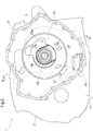
FIG. 2] FIG. 2 is a diagram of the vehicle drive apparatus as viewed from a location toward a rotary electric machine in an axial direction. - [
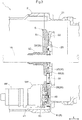
FIG. 3] FIG. 3 is a cross-sectional view of the vehicle drive apparatus taken along the line III-III inFIG. 2 . - [
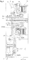
FIG. 4] FIG 4 is a diagram of the vehicle drive apparatus to which a support member and a chain cover are assembled. - [
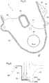
FIG. 5] FIG. 5 is a plan view of the chain cover. - [
FIG. 6] FIG. 6 is a cross-sectional view taken along the line VI-VI inFIG. 5 . - [
FIG. 7] FIG. 7 is a diagram of the vehicle drive apparatus as viewed from a location toward a transmission in the axial direction. - [
FIG. 8] FIG 8 is a diagram of a support member assembled to a case of a vehicle drive apparatus according to a second embodiment, as viewed from a location toward a rotary electric machine in an axial direction. - [
FIG. 9] FIG. 9 is a cross-sectional view taken along the line IX-IX inFIG. 8 . - [
FIG. 10] FIG. 10 is a cross-sectional view taken along the line X-X inFIG. 8 . - [
FIG. 11] FIG. 11 is a diagram of the vehicle drive apparatus as viewed from a location toward a transmission in the axial direction. - A vehicle drive apparatus according to a first embodiment will be described with reference to the drawings. The
vehicle drive apparatus 1 according to the present embodiment is an apparatus for driving a hybrid vehicle (hereinafter referred to as a "hybrid vehicle drive apparatus"). The hybrid vehicle drive apparatus includes both of an internal combustion engine EG and a rotaryelectric machine 13 each functioning as a driving force source for wheels W. Thevehicle drive apparatus 1 transmits a torque (which is generated by at least one of the internal combustion engine EG and the rotary electric machine 13) to the wheels W so as to cause a vehicle to travel. Thevehicle drive apparatus 1 according to the present embodiment is provided in the form of an apparatus for driving a front-engine front-drive (FF) vehicle. - As illustrated in
FIG. 1 , thevehicle drive apparatus 1 includes: aninput member 11 drivingly connected to the internal combustion engine EG; afriction engagement device 12; the rotaryelectric machine 13; atransmission 16; andoutput members 17 drivingly connected to the wheels W. Theinput member 11, thefriction engagement device 12, the rotaryelectric machine 13, thetransmission 16, and theoutput members 17 are provided in this order from a location toward the internal combustion engine EG along a power transmission path connecting the internal combustion engine EG to the wheels W. Theinput member 11, thefriction engagement device 12, the rotaryelectric machine 13, thetransmission 16, and theoutput members 17 are housed in a case (drive apparatus case) 2. - As used herein, the term "drivingly connected to" refers to a state where two rotary elements are connected to each other such that a driving force is transmittable therebetween. This concept encompasses not only a state where two rotary elements are connected to each other such that the two rotary elements rotate together, but also a state where two rotary elements are connected to each other through one or more transmission members such that a driving force is transmittable therebetween. Such transmission members include various members (e.g., a shaft, a gear mechanism, a belt, and a chain) that transmit rotation at equal or varying speeds. Such transmission members may include engagement devices (e.g., a friction engagement device and a meshing type engagement device) that transmit rotation and driving force selectively.
- As used herein, the term "rotary electric machine" is a concept encompassing all of a motor (electric motor), a generator (power generator), and a motor generator that functions as both of a motor and a generator when necessary.
- The
input member 11 is drivingly connected to the internal combustion engine EG. The internal combustion engine EG is a motor (e.g., a gasoline engine or a diesel engine) to be driven by fuel combustion inside the engine such that power is derived therefrom. Theinput member 11 is drivingly connected to an output shaft (e.g., a crankshaft) of the internal combustion engine EG. Theinput member 11 is connected to the output shaft of the internal combustion engine EG such that theinput member 11 rotates together with the output shaft, or drivingly connected to the output shaft of the internal combustion engine EG through a different member, such as a damper. Theinput member 11 is drivingly connected to the rotaryelectric machine 13 through thefriction engagement device 12. - The
friction engagement device 12 connects theinput member 11 to the rotaryelectric machine 13 selectively. In other words, thefriction engagement device 12 is able to disconnect the internal combustion engine EG from the rotaryelectric machine 13. Thefriction engagement device 12 functions as an engagement device for internal combustion engine disconnection, which disconnects the internal combustion engine EG from thevehicle drive apparatus 1. Thefriction engagement device 12 is a hydraulically operated friction engagement device. For example, a clutch, such as a wet multi-plate clutch, may be used as thefriction engagement device 12. - The
friction engagement device 12 includesfriction engagement elements 12a. Thefriction engagement elements 12a are, for example, a plurality of friction plates stacked in an axial direction L. Engagement of thefriction engagement elements 12a brings theinput member 11 and the rotaryelectric machine 13 into a connected state. Thefriction engagement elements 12a may be brought into sliding engagement (i.e., slip engagement). This enables thefriction engagement device 12 to transmit power, with theinput member 11 and the rotaryelectric machine 13 rotating at different speeds. - The rotary
electric machine 13 is disposed radially outward of thefriction engagement device 12. The rotaryelectric machine 13 includes: astator 13s secured to thecase 2; and arotor 13r rotatably supported at a location radially inward of thestator 13s. The rotaryelectric machine 13 performs power running upon receiving supply of electric power from a power storage device (not illustrated), or supplies electric power (which is generated by, for example, a torque of the internal combustion engine EG and/or an inertial force of the vehicle) to the power storage device such that the electric power is stored in the power storage device. Therotor 13r is drivingly connected to theinput member 11 through thefriction engagement device 12 and is connected to arotor connecting member 14 such that therotor 13r rotates together with therotor connecting member 14. Therotor connecting member 14 is connected to atransmission input member 15 such that therotor connecting member 14 rotates together with thetransmission input member 15. Thetransmission input member 15 is an input member of thetransmission 16. - The
transmission 16 changes the rotation speed of thetransmission input member 15 in accordance with a predetermined speed ratio and transmits the resulting rotation speed to theoutput members 17. As used herein, the term "speed ratio" refers to the ratio of the rotation speed of thetransmission input member 15 to the rotation speed of theoutput members 17. The speed ratio is a value calculated by dividing the rotation speed of thetransmission input member 15 by the rotation speed of theoutput members 17. Examples of thetransmission 16 may include a stepped automatic transmission, a stepped manual transmission, and an automatic continuously variable transmission. Thetransmission 16 may include, for example, a counter gear mechanism and/or a differential mechanism. In the present embodiment, a pair of right and leftoutput members 17 is drivingly connected to a differential mechanism, and the wheels W are each drivingly connected to an associated one of the right and leftoutput members 17. - As illustrated in
FIG. 1 , thevehicle drive apparatus 1 according to the present embodiment further includes a mechanical oil pump MP and apump drive mechanism 3 to drive the mechanical oil pump MP Thepump drive mechanism 3 includes: aselector 31 to select a power source for driving the mechanical oil pump MP; and achain drive 36 to transmit, to the mechanical oil pump MP, a driving force provided from the power source selected by theselector 31. In the present embodiment, the mechanical oil pump MP is equivalent to an "oil pump". - The
selector 31 includes a first one-way clutch F1, a second one-way clutch F2, an inputgear forming member 32, agear row 33, and an outputgear forming member 34. The first one-way clutch F1 is engaged when the rotation speed of theinput member 11 is equal to or higher than the rotation speed of the inputgear forming member 32. The first one-way clutch F1 is disengaged when the rotation speed of theinput member 11 is lower than the rotation speed of the inputgear forming member 32. The second one-way clutch F2 is engaged when the rotation speed of thetransmission input member 15 is equal to or higher than the rotation speed of the inputgear forming member 32. The second one-way clutch F2 is disengaged when the rotation speed of thetransmission input member 15 is lower than the rotation speed of the inputgear forming member 32. Thus, a driving force is transmitted from either one of the internal combustion engine EG (or the input member 11) and the rotaryelectric machine 13 whose rotation speed is higher to the inputgear forming member 32. When the internal combustion engine EG (or the input member 11) and the rotaryelectric machine 13 rotate at equal speed, a driving force is transmitted from both of the internal combustion engine EG (or the input member 11) and the rotaryelectric machine 13 to the inputgear forming member 32. - The input
gear forming member 32 is drivingly connected to the outputgear forming member 34 through thegear row 33. Afirst sprocket 37 of thechain drive 36 is secured to the outputgear forming member 34. - The
chain drive 36 includes thefirst sprocket 37, asecond sprocket 38, and achain 39. Thefirst sprocket 37 is secured to the outputgear forming member 34. Thesecond sprocket 38 is secured to apump shaft 46 of the mechanical oil pump MP. Thechain 39 is wound around thefirst sprocket 37 and thesecond sprocket 38. Thechain drive 36 transmits rotation of the outputgear forming member 34 to thepump shaft 46. Thus, the mechanical oil pump MP is drivable by the driving force transmitted from either one of the internal combustion engine EG (or the input member 11) and the rotaryelectric machine 13 whose rotation speed is higher. When the internal combustion engine EG (or the input member 11) and the rotaryelectric machine 13 rotate at equal speed, the mechanical oil pump MP is drivable by the driving force transmitted from both of the internal combustion engine EG (or the input member 11) and the rotaryelectric machine 13. - In the present embodiment, an electric oil pump EP (see
FIG. 3 ) is provided in addition to the mechanical oil pump MP. The electric oil pump EP is driven by a dedicated drive motor (not illustrated). - As illustrated in
FIGS. 2 and3 , thecase 2 includes: aperipheral wall 21 covering the outside of components, such as thefriction engagement device 12, the rotaryelectric machine 13, and thetransmission 16; a pair of end walls (not illustrated) covering the ends of thefriction engagement device 12, the rotaryelectric machine 13, and thetransmission 16 in the axial direction L; and anintermediate wall 22. Theintermediate wall 22 is disposed between thefriction engagement device 12 and thetransmission 16 and between the rotaryelectric machine 13 and thetransmission 16 in the axial direction L. Specifically, theintermediate wall 22 divides the inner space of thecase 2 into: a space (first space) in which thefriction engagement device 12 and the rotaryelectric machine 13 are mainly housed; and a space (second space) in which thetransmission 16 is mainly housed. - As illustrated in
FIG. 3 , anoil reservoir 41 is defined inside thecase 2. Theoil reservoir 41 stores oil that is an automatic transmission fluid (ATF). Theoil reservoir 41 is defined in an internal space of thecase 2 at a location closer to thetransmission 16 than theintermediate wall 22 in the axial direction L. The mechanical oil pump MP and the electric oil pump EP are each driven by the drive motor and at least one of the internal combustion engine EG and the rotaryelectric machine 13 so as to discharge the oil stored in theoil reservoir 41. - The pressure of oil discharged from at least one of the mechanical oil pump MP and the electric oil pump EP is adjusted by a hydraulic controller 42 (see
FIG. 4 ). The resulting oil is supplied to the components of thevehicle drive apparatus 1. In one example, the oil whose pressure has been adjusted to a predetermined pressure in accordance with a hydraulic command value is supplied to, for example, a hydraulic servo of thefriction engagement device 12 and/or a hydraulic servo of a clutch brake in thetransmission 16. In another example, a portion of the oil is supplied to, for example, thefriction engagement elements 12a of thefriction engagement device 12, friction engagement elements of the clutch brake in thetransmission 16, and/or thestator 13s of the rotaryelectric machine 13. - In the present embodiment, the
selector 31 is disposed toward the internal combustion engine EG relative to theintermediate wall 22 in the axial direction L, and thechain drive 36 is disposed toward thetransmission 16 relative to theintermediate wall 22 in the axial direction L. Thechain drive 36 is disposed adjacent to theintermediate wall 22. Thechain drive 36 is supported by asupport member 5 secured to theintermediate wall 22 from a location toward thetransmission 16. Thechain drive 36 thus supported is disposed adjacent to theintermediate wall 22. Thechain drive 36 is disposed in a clearance created between theintermediate wall 22 and thesupport member 5 in the axial direction L. - As illustrated in
FIGS. 3 and4 , thesupport member 5 consists mainly of abody 51 formed into an oddly shaped plate. Thebody 51 is provided with: acylindrical insertion shaft 52, aninsertion hole 53, and alarge opening 54. Each of theinsertion hole 53 and thelarge opening 54 is a through hole passing through thebody 51 in the axial direction L. Theinsertion shaft 52 is formed to protrude from thebody 51 in a direction opposite to the intermediate wall 22 (i.e., toward the transmission 16). Thetransmission input member 15 is inserted through a radially inner portion of theinsertion shaft 52. Theinsertion hole 53 is provided in the form of a round hole. A portion of a pump cover of the mechanical oil pump MP and thepump shaft 46 are inserted through a radially inner portion of theinsertion hole 53. Thelarge opening 54 is provided in the form of an elongated opening larger than theinsertion shaft 52 and theinsertion hole 53. Thelarge opening 54 is provided between theinsertion shaft 52 and theinsertion hole 53. - The
first sprocket 37, which is a component of thechain drive 36, is disposed coaxially with theinsertion shaft 52. Thesecond sprocket 38 is disposed coaxially with theinsertion hole 53. Thechain 39 wound around thefirst sprocket 37 and thesecond sprocket 38 is disposed to partially overlap with thelarge opening 54 as viewed in the axial direction L. A region where thechain 39 is placed will hereinafter be referred to as a "chain placement region CH" (see the shaded region inFIG. 7 ). The chain placement region CH includes a portion overlapping with thelarge opening 54 as viewed in the axial direction L. - A
chain cover 6 is disposed in a clearance created between theintermediate wall 22 and thesupport member 5 in the axial direction L. Thechain cover 6 is secured to thesupport member 5 so as to cover the chain placement region CH from a location toward the transmission 16 (or the support member 5) in the axial direction L. As illustrated inFIGS. 4 and5 , thechain cover 6 includes at least acover member 61 partially covering a lower portion of the chain placement region CH (i.e., a portion of the chain placement region CH located adjacent to the second sprocket 38). - The
cover member 61 includes: a coveringplate 62 formed into an oddly shaped flat plate; a pumpshaft insertion portion 63 defined in an inner region of the coveringplate 62; atubular portion 64; and avertical wall 65. Thetubular portion 64 and thevertical wall 65 are formed to include an outer edge of the coveringplate 62. The pumpshaft insertion portion 63 is a region through which thepump shaft 46 is inserted. In the present embodiment, the pumpshaft insertion portion 63 is formed to protrude from the coveringplate 62 toward thetransmission 16 in the axial direction L. The coveringplate 62 is disposed so as to cover a portion of the chain placement region CH from a location toward thetransmission 16 in the axial direction L, with the pumpshaft insertion portion 63 externally fitted to the pump cover of the mechanical oil pump MP (seeFIGS. 3 and6 ). - The
tubular portion 64 and thevertical wall 65 are formed to protrude from the coveringplate 62 in a direction opposite to the pumpshaft insertion portion 63 in the axial direction L (i.e., toward the internal combustion engine EG). Thetubular portion 64 is located in a substantially central portion of the upper edge of the coveringplate 62 and has a substantially rectangular tubular shape with an end edge. Thevertical wall 65 is formed continuously along the end edge of a region of the coveringplate 62 except its upper edge. As illustrated inFIG. 6 , thevertical wall 65 includes: asupport piece 65A rising substantially vertically from the coveringplate 62; and a coveringrubber 65B attached to thesupport piece 65A. The pumpshaft insertion portion 63, the coveringplate 62, and thesupport piece 65A may be made of a rigid material (e.g., a sheet metal) and may thus be integral with each other. The coveringrubber 65B may be made of a material (e.g., a rubber plate) that is more elastic than, for example, thesupport piece 65A. A tip of the coveringrubber 65B is tapered such that the tip is reduced in thickness toward its extremity. Thetubular portion 64 may have the same structure as thevertical wall 65. - With the
cover member 61 secured to thesupport member 5 and thesupport member 5 secured to theintermediate wall 22, the tip of the vertical wall 65 (i.e., the tip of the coveringrubber 65B) in an elastically deformed state is in abutment with theintermediate wall 22. Similarly, the tip of thetubular portion 64 in an elastically deformed state is in abutment with theintermediate wall 22. Such an arrangement is particularly advantageous when a surface of theintermediate wall 22 facing toward thetransmission 16 is not completely flat but somewhat uneven. - In the present embodiment, the
chain cover 6 further includes anauxiliary member 66 in addition to thecover member 61. Theauxiliary member 66 includes an elongated mountingplate 67 and avertical wall 68 formed along a side of the mountingplate 67. The mountingplate 67 and thesupport member 5 are tightened together when the mountingplate 67 is secured to thesupport member 5. Thevertical wall 68 may have the same structure as thevertical wall 65 of thecover member 61. Specifically, thevertical wall 68 may include: a support piece rising substantially vertically from the mountingplate 67; and a covering rubber attached to the support piece. Theauxiliary member 66 is secured to thesupport member 5 such that thevertical wall 68 of theauxiliary member 66 extends from an end of thevertical wall 65 of thecover member 61 substantially along a tangent to the end of thevertical wall 65. - With the
auxiliary member 66 secured to thesupport member 5 and thesupport member 5 secured to theintermediate wall 22, the tip of the vertical wall 68 (i.e., the tip of the covering rubber) in an elastically deformed state is in abutment with theintermediate wall 22. Such an arrangement is particularly advantageous when the surface of theintermediate wall 22 facing toward thetransmission 16 is not completely flat but somewhat uneven. - As described above, a portion of oil discharged from at least one of the mechanical oil pump MP and the electric oil pump EP is supplied to, for example, the
friction engagement elements 12a of thefriction engagement device 12 and/or thestator 13s of the rotaryelectric machine 13 for cooling, lubrication, and/or other purposes. These components are located closer to the internal combustion engine EG than theintermediate wall 22 in the axial direction L. In contrast, theoil reservoir 41 is defined in an internal space of thecase 2 at a location closer to thetransmission 16 than theintermediate wall 22 in the axial direction L. Accordingly, oil that has served its purpose(s), such as cooling, lubrication, and/or other purposes, (i.e., oil discharged from thefriction engagement elements 12a and/or the rotary electric machine 13) flows beyond theintermediate wall 22 in the axial direction L and is thus returned to theoil reservoir 41. - The
intermediate wall 22 is provided with at least one opening such that oil is allowed to flow beyond theintermediate wall 22 in the axial direction L. As illustrated inFIG. 7 , theintermediate wall 22 according to the present embodiment is provided with a plurality of openings. More specifically, theintermediate wall 22 is provided with at least alarge opening 25, a firstsmall opening 26, and a secondsmall opening 27. Thelarge opening 25 is formed such that thelarge opening 25 is coaxial with thefirst sprocket 37, which is a component of thechain drive 36, and has a size enough to allow thefirst sprocket 37 to be located within thelarge opening 25 as viewed in the axial direction L. Thelarge opening 25 includes a perfect circle opening and a projectingregion 25a projecting radially outward from the perfect circle opening. The firstsmall opening 26 and the secondsmall opening 27 are defined at different circumferential positions and similar radial positions relative to the rotation axis of thefirst sprocket 37. The firstsmall opening 26 is defined inward of an inner peripheral edge Ei of the chain placement region CH having an annular shape. The secondsmall opening 27 is defined outward of an outer peripheral edge Eo of the annular chain placement region CH. - In the present embodiment, oil discharged from the
friction engagement elements 12a of thefriction engagement device 12 returns toward theoil reservoir 41 through the projectingregion 25a of thelarge opening 25 and the firstsmall opening 26 defined in theintermediate wall 22. In the present embodiment, the projectingregion 25a of thelarge opening 25 and the firstsmall opening 26 are equivalent to a "return oil hole". - As illustrated in
FIG. 7 , a portion of the chain placement region CH is located below the projectingregion 25a of thelarge opening 25 at a location adjacent to a portion of theintermediate wall 22 toward thetransmission 16. Thus, oil that has reached a location toward thetransmission 16 through the projectingregion 25a of theintermediate wall 22 unfortunately enters the chain placement region CH if the oil flows straight down. The present embodiment, however, involves placing the chain cover 6 (or specifically, the auxiliary member 66) such that theauxiliary member 66 is interposed between the projectingregion 25a and the chain placement region CH. Theauxiliary member 66 is secured to thesupport member 5 through the mountingplate 67 and is in abutment with theintermediate wall 22, with the tip of thevertical wall 68 elastically deformed. Accordingly, if oil flows down from the projectingregion 25a, the oil would be blocked by thevertical wall 68 of theauxiliary member 66 and would then flow along the outer surface of thevertical wall 68. Consequently, the oil is prevented from reaching (or entering) the chain placement region CH. - A portion of the chain placement region CH is located below the first
small opening 26 at a location adjacent to a portion of theintermediate wall 22 toward thetransmission 16. Thus, oil that has reached a location toward thetransmission 16 through the firstsmall opening 26 of theintermediate wall 22 unfortunately enters the chain placement region CH if the oil flows straight down. The present embodiment, however, involves placing the chain cover 6 (or specifically, thetubular portion 64 of the cover member 61) such that thetubular portion 64 surrounds the entire periphery of the firstsmall opening 26. Thetubular portion 64 is in abutment with theintermediate wall 22, with thecover member 61 secured to thesupport member 5 and the tip of thetubular portion 64 elastically deformed. Accordingly, oil flowing from the firstsmall opening 26 is blocked by thetubular portion 64 and then flows along the inner surface of thetubular portion 64 in the axial direction L. Thetubular portion 64 is in communication with afirst region 54a (seeFIG. 4 ) of thelarge opening 54 defined in thesupport member 5, so that the oil returns to theoil reservoir 41 through thefirst region 54a. Consequently, the oil is prevented from reaching (or entering) the chain placement region CH. - As described above, the present embodiment involves providing the chain cover 6 (i.e., the
cover member 61 and the auxiliary member 66). Thus, the present embodiment is able to guide oil from the projectingregion 25a of thelarge opening 25 and the firstsmall opening 26 of theintermediate wall 22 to regions other than the chain placement region CH inside thecase 2. When the projectingregion 25a and the firstsmall opening 26 are inherently located in regions other than the chain placement region CH, the present embodiment is able to prevent oil, which is flowing from the projectingregion 25a and the firstsmall opening 26, from reaching the chain placement region CH. Consequently, the present embodiment is able to reduce the amount of oil entering the chain placement region CH, thus making it possible to prevent or reduce excessive oil agitation. - In the present embodiment, oil discharged from the rotary
electric machine 13 returns toward theoil reservoir 41 through the secondsmall opening 27. In the present embodiment, the secondsmall opening 27 is equivalent to a "second return oil hole". An opening of the secondsmall opening 27 located toward the transmission 16 (or toward the oil reservoir 41) is disposed outward of the outer peripheral edge Eo of the annular chain placement region CH. In particular, the opening of the secondsmall opening 27 is disposed below and outward of the outer peripheral edge Eo of the chain placement region CH. Consequently, oil flowing straight down from the secondsmall opening 27 will not reach (or enter) the chain placement region CH. - In addition, the present embodiment involves placing the chain cover 6 (or specifically, the
vertical wall 65 of the cover member 61) such that thevertical wall 65 is interposed between the secondsmall opening 27 and the chain placement region CH. Thevertical wall 65 is in abutment with theintermediate wall 22, with thecover member 61 secured to thesupport member 5 and the tip of thevertical wall 65 elastically deformed. Thus, if oil flowing from the secondsmall opening 27 scatters, the scattered oil would be blocked by thevertical wall 65 of thecover member 61 and would then flow along the outer surface of thevertical wall 65. Consequently, the oil is more reliably prevented from reaching (or entering) the chain placement region CH. - As described above, the present embodiment involves providing the chain cover 6 (or in particular, the cover member 61). Thus, the present embodiment is also able to prevent the oil, which is flowing from the second
small opening 27 of theintermediate wall 22, from reaching the chain placement region CH. Accordingly, the present embodiment is able to effectively reduce the amount of oil entering the chain placement region CH. In the present embodiment, thevertical wall 68, thetubular portion 64, and thevertical wall 65, which are portions of thechain cover 6, define an "oil guide OG". - Effectively reducing the amount of oil entering the chain placement region CH makes it possible to effectively prevent or reduce excessive oil agitation. Preventing or reducing oil agitation makes it possible to prevent or reduce bubbling in the mechanical oil pump MP and the electric oil pump EP and to maintain the amount of oil suction at a suitable level.
- A vehicle drive apparatus according to a second embodiment will be described with reference to the drawings. The second embodiment differs from the first embodiment in that the
vehicle drive apparatus 1 according to the second embodiment includes nochain cover 6. Accordingly, the specific structures of theintermediate wall 22 and thesupport member 5 in the second embodiment are different from those in the first embodiment. The following description focuses mainly on the differences between thevehicle drive apparatus 1 according to the second embodiment and thevehicle drive apparatus 1 according to the first embodiment. Unless otherwise specified, elements similar to those of the first embodiment will be identified by the same reference signs and will not be described in detail. - As illustrated in
FIGS. 8 to 10 , theintermediate wall 22 of thecase 2 of thevehicle drive apparatus 1 according to the present embodiment is provided with agutter 23 and arib 24. Thegutter 23 and therib 24 are formed to protrude from theintermediate wall 22 toward thetransmission 16 in the axial direction L. Thegutter 23 includes: a bottom wall covering a target region from below; and a pair of side walls covering the circumferential sides of the target region. Thegutter 23 is disposed inward of the annular chain placement region CH as viewed in the axial direction L. Thegutter 23 is formed to extend toward thetransmission 16 such that thegutter 23 is located closer to thetransmission 16 than thesprockets chain 39 in the axial direction L. Therib 24 has a linear shape. Therib 24 is disposed to assume an inclined position such that therib 24 faces obliquely downward. Therib 24 is disposed outward of the chain placement region CH as viewed in the axial direction L. Afirst rib 55 is protruded from thesupport member 5. Thegutter 23 is in abutment with thefirst rib 55 in the axial direction L. - The
support member 5 secured to theintermediate wall 22 from a location toward thetransmission 16 is provided with thefirst rib 55 and asecond rib 56. Thefirst rib 55 and thesecond rib 56 are formed to protrude from thebody 51 toward the rotaryelectric machine 13 in the axial direction L. Thefirst rib 55 is disposed outward of the chain placement region CH as viewed in the axial direction L. Thefirst rib 55 is in abutment with the rib 24 (which is protruded from the intermediate wall 22) in the axial direction L. Thesecond rib 56 is disposed above the chain placement region CH. - As illustrated in
FIG. 11 , thelarge opening 25 defined in theintermediate wall 22 according to the present embodiment includes two projecting regions, i.e., an upper projectingregion 25b and a lower projectingregion 25c. The upper projectingregion 25b is an opening region corresponding to the projectingregion 25a according to the first embodiment (seeFIG. 7 ). The lower projectingregion 25c is defined in a lower end region of thelarge opening 25. Thegutter 23 is formed around the lower projectingregion 25c. Oil discharged from thefriction engagement elements 12a of thefriction engagement device 12 returns toward theoil reservoir 41 through the upper projectingregion 25b and the lower projectingregion 25c of thelarge opening 25 defined in theintermediate wall 22. In the present embodiment, the upper projectingregion 25b and the lower projectingregion 25c of thelarge opening 25 are equivalent to the "return oil hole". - A portion of the chain placement region CH is located below the lower projecting
region 25c of thelarge opening 25 at a location adjacent to a portion of theintermediate wall 22 toward thetransmission 16. Thus, oil that has reached a location toward thetransmission 16 through the lower projectingregion 25c unfortunately enters the chain placement region CH if the oil flows straight down. The present embodiment, however, involves providing thegutter 23 on theintermediate wall 22 such that thegutter 23 covers the periphery of the lower projectingregion 25c from below. Accordingly, oil flowing from the lower projectingregion 25c is blocked by thegutter 23, then flows along the inner surface of thegutter 23 in the axial direction L, and eventually returns to theoil reservoir 41. Consequently, the oil is prevented from reaching (or entering) the chain placement region CH. - A portion of the chain placement region CH is located below the upper projecting
region 25b of thelarge opening 25 at a location adjacent to a portion of theintermediate wall 22 toward thetransmission 16. Thus, oil that has reached a location toward thetransmission 16 through the upper projectingregion 25b of thelarge opening 25 unfortunately enters the chain placement region CH if the oil flows straight down. The present embodiment, however, involves providing thefirst rib 55 and thesecond rib 56 on thesupport member 5 and providing the rib 24 (which abuts on the first rib 55) on theintermediate wall 22 such that thefirst rib 55, thesecond rib 56, and therib 24 are interposed between the upper projectingregion 25b and the chain placement region CH. Accordingly, oil flowing down from the upper projectingregion 25b is blocked by thesecond rib 56 of thesupport member 5 and then flows along the outer surface of thesecond rib 56. Oil flowing down from thesecond rib 56 is blocked byfirst rib 55 of thesupport member 5 and therib 24 of the intermediate wall 22 (which are in abutment with each other in the axial direction L) and then flows along the outer surfaces of thefirst rib 55 and therib 24. Consequently, the oil is prevented from reaching (or entering) the chain placement region CH. - As described above, the present embodiment involves changing the shapes of the
intermediate wall 22 and the support member 5 (or specifically, involves providing thegutter 23, therib 24, thefirst rib 55, and the second rib 56). Thus, the present embodiment is able to guide oil from the upper projectingregion 25b and the lower projectingregion 25c of thelarge opening 25 of theintermediate wall 22 to regions other than the chain placement region CH inside thecase 2. When the upper projectingregion 25b and the lower projectingregion 25c are inherently located in regions other than the chain placement region CH, the present embodiment is able to prevent the oil, which is flowing from the upper projectingregion 25b and the lower projectingregion 25c, from reaching the chain placement region CH. Consequently, the present embodiment is able to reduce the amount of oil entering the chain placement region CH. In the present embodiment, thegutter 23 and therib 24 of theintermediate wall 22 and thefirst rib 55 and thesecond rib 56 of thesupport member 5 define the "oil guide OG". - Effectively reducing the amount of oil entering the chain placement region CH as described above makes it possible to effectively prevent or reduce excessive oil agitation. Preventing or reducing oil agitation makes it possible to prevent or reduce bubbling in the mechanical oil pump MP and the electric oil pump EP and to maintain the amount of oil suction at a suitable level. The present embodiment eliminates the need for the use of the
chain cover 6 by changing the shapes of theintermediate wall 22 and thesupport member 5. The present embodiment is thus able to maintain the amount of oil suction at a suitable level as mentioned above while promoting cost reduction. -
- (1) The first embodiment has been described by way of example as having a structure in which a portion of the
chain cover 6 defines the oil guide OG The present invention, however, is not limited to this structure. In one example, dedicated component(s) may be used to define the oil guide OG - (2) The first embodiment has been described by way of example as having a structure in which the
vertical wall 65 of thecover member 61, which is a component of thechain cover 6, includes thesupport piece 65A and the coveringrubber 65B attached thereto, and the tip of the coveringrubber 65B in an elastically deformed state is in abutment with theintermediate wall 22. The present invention, however, is not limited to this structure. In one example, the tip of the coveringrubber 65B may abut on theintermediate wall 22 while undergoing substantially no elastic deformation. In another example, thevertical wall 65 may consist of a member integral with the coveringplate 62, the pumpshaft insertion portion 63, and thetubular portion 64 instead of being made up of two members including the coveringrubber 65B. - (3) The first embodiment has been described by way of example as having a structure in which the
vertical wall 65 of thecover member 61 is disposed such that thevertical wall 65 is interposed between the secondsmall opening 27 and the chain placement region CH. The present invention, however, is not limited to this structure. As long as the opening of the secondsmall opening 27 is disposed below and outward of the outer peripheral edge Eo of the chain placement region CH, thevertical wall 65 of thecover member 61 does not necessarily have to be interposed between the secondsmall opening 27 and the chain placement region CH. - (4) The specific structures of the
intermediate wall 22, thesupport member 5, and thechain cover 6, which have been described in the foregoing embodiments, are only illustrative. The details of the specific structures may be changed as appropriate for application. - (5) The structure(s) disclosed in the above-described embodiments may be combined with structure(s) disclosed in other embodiment(s) for application, as long as no contradiction arises. The above-described embodiments include the foregoing embodiments and the alternative embodiments. The same goes for the following description. Other structures of the embodiments disclosed herein are illustrative in all respects and may be changed as appropriate without departing from the scope of the present disclosure.
- In summary, the vehicle drive apparatus according to the present disclosure preferably has the following structures.
- The vehicle drive apparatus includes: an input member (11) drivingly connected to an internal combustion engine (EG); an output member (17) drivingly connected to a wheel (W); a friction engagement device (12); a rotary electric machine (13) drivingly connected to the input member (11) through the friction engagement device (12); a transmission (16) disposed between the rotary electric machine (13) and the output member (17); an oil pump (MP); and a case (2) housing the input member (11), the output member (17), the friction engagement device (12), the rotary electric machine (13), the transmission (16), and the oil pump (MP).
- The case (2) includes an intermediate wall (22) disposed between the friction engagement device (12) and the transmission (16) and between the rotary electric machine (13) and the transmission (16) in an axial direction (L).
- An oil reservoir (41) to store oil is defined in an internal space of the case (2) at a location closer to the transmission (16) than the intermediate wall (22).
- The oil pump (MP) supplies oil stored in the oil reservoir (41) to a friction engagement element (12a) of the friction engagement device (12).
- The intermediate wall (22) is provided with a return oil hole (25a, 25b, 25c, 26) through which oil discharged from the friction engagement element (12a) returns toward the oil reservoir (41).
- A chain drive (36) is disposed adjacent to a portion of the intermediate wall (22) toward the transmission (16). The chain drive (36) includes a chain (39) to transmit a driving force from at least one of the input member (11) and the rotary electric machine (13) to the oil pump (MP).
- The vehicle drive apparatus further includes an oil guide (OG) through which oil flowing through the return oil hole (25a, 25b, 25c, 26) is guided to a region other than a chain placement region (CN) inside the case (2). The chain placement region (CH) is a region where the chain (39) is placed.
- The oil flowing through the return oil hole (25a, 25b, 25c, 26) is guided through the oil guide and returned to the oil reservoir.
- This structure includes the oil guide (OG). Thus, oil flowing toward the transmission (16) through the return oil hole (25a, 25b, 25c, 26) defined in the intermediate wall (22) of the case (2) is returnable to the oil reservoir (41) through a region other than the chain placement region (CH), i.e., through a region where no chain (39) is placed. Accordingly, if the chain drive (36) is disposed adjacent to the intermediate wall (22) provided inside the case (2), this structure would reduce the amount of oil that enters the chain placement region (CH) of the chain drive (36) after having reached a location toward the oil reservoir (41) through the return oil hole (25a, 25b, 25c, 26). Consequently, this structure is able to reduce or prevent an increase in oil agitation caused by the chain.
- In one aspect, the vehicle drive apparatus preferably includes a chain cover (6) covering the chain placement region (CH).
- The chain cover (6) is preferably secured to the intermediate wall (22) from a location toward the transmission (16).
- At least a portion of the oil guide (OG) is preferably formed by the chain cover (6).
- This structure involves securing the chain cover (6) to the intermediate wall (22) from the location toward the transmission (16) and is thus able to form at least a portion of the oil guide (OG) using the chain cover (6). This makes it possible to easily reduce or prevent an increase in oil agitation caused by the chain with a relatively simple structure. This structure involves covering the chain placement region (CH) with the chain cover (6) and is thus able to reduce the amount of oil entering the chain placement region (CH) from regions other than the return oil hole (25a, 25b, 25c, 26). Consequently, this structure is able to reduce oil agitation caused by the chain.
- In another aspect, the intermediate wall (22) is preferably provided with a second return oil hole (27) through which oil discharged from the rotary electric machine (13) returns toward the oil reservoir (41).
- An opening of the second return oil hole (27) located toward the oil reservoir (41) is preferably disposed at a location outward of an outer peripheral edge (Eo) of the chain placement region (CH) having an annular shape, such that oil discharged from the second return oil hole (27) is prevented from entering the chain placement region (CH).
- In this structure, oil flowing toward the oil reservoir (41) through the second return oil hole (27) defined in the intermediate wall (22) of the case (2) is guidable to a region which is located outward of the chain placement region (CH) and in which no chain (39) is placed. Accordingly, this structure is also able to reduce the amount of oil that enters the chain placement region (CH) of the chain drive (36) after having reached a location toward the oil reservoir (41) through the second return oil hole (27). Consequently, this structure is able to reduce or prevent an increase in oil agitation caused by the chain.
- In still another aspect, the oil guide (OG) preferably includes a tubular portion (64) which passes through a region inward of an outer peripheral edge (Ei) of the annular chain placement region (CH) in the axial direction (L) and through which the return oil hole (25a, 25b, 25c, 26) is in communication with the oil reservoir (41).
- In this structure, oil flowing toward the oil reservoir (41) through the return oil hole (25a, 25b, 25c, 26) defined in the intermediate wall (22) of the case (2) is allowed to pass through a region which is located inward of the chain placement region (CH) and in which no chain (39) is placed. Accordingly, this structure is able to reduce the amount of oil that enters the chain placement region (CH) of the chain drive (36) after having reached a location toward the oil reservoir (41) through the return oil hole (25a, 25b, 25c, 26). Consequently, an increase in oil agitation caused by the chain is preventable or reducible with a simple structure.
- In yet another aspect, the return oil hole (25a, 25b, 25c, 26) is preferably provided to include a region of the intermediate wall (22) facing a lower end of the friction engagement element (12a).
- In this structure, oil that has cooled the friction engagement element (12a) of the friction engagement device (12) and has then been discharged therefrom is suitably returnable toward the oil reservoir (41) through the return oil hole (25a, 25b, 25c, 26).
- In still yet another aspect, the intermediate wall (22) is preferably provided with a second return oil hole (27) through which oil discharged from the rotary electric machine (13) returns toward the oil reservoir (41).
- The return oil hole (25a, 25b, 25c, 26) and the second return oil hole (27) are preferably provided independently of each other.
- In this structure, oil that has cooled the friction engagement element (12a) of the friction engagement device (12) and has then been discharged therefrom, and oil that has cooled the rotary electric machine (13) and has then been discharged therefrom are returnable toward the oil reservoir (41) through the return oil hole (25a, 25b, 25c, 26) and the second return oil hole (27), respectively.
- The vehicle drive apparatus according to the present disclosure preferably achieves at least one of the effects described above.
-
- 1
- vehicle drive apparatus
- 2
- case
- 6
- chain cover
- 11
- input member
- 12
- friction engagement device
- 12a
- friction engagement element
- 13
- rotary electric machine
- 16
- transmission
- 17
- output member
- 22
- intermediate wall
- 25a
- projecting region (return oil hole)
- 25b
- upper projecting region (return oil hole)
- 25c
- lower projecting region (return oil hole)
- 26
- first small opening (return oil hole)
- 27
- second small opening (second return oil hole)
- 28
- small opening (second return oil hole)
- 36
- chain drive
- 39
- chain
- 41
- oil reservoir
- EG
- internal combustion engine
- W
- wheel
- MP
- mechanical oil pump (oil pump)
- OG
- oil guide
- CH
- chain placement region
- Ei
- inner peripheral edge
- Eo
- outer peripheral edge
- L
- axial direction
Claims (6)
- A vehicle drive apparatus comprising: an input member drivingly connected to an internal combustion engine; an output member drivingly connected to a wheel; a friction engagement device; a rotary electric machine drivingly connected to the input member through the friction engagement device; a transmission disposed between the rotary electric machine and the output member; an oil pump; and a case housing the input member, the output member, the friction engagement device, the rotary electric machine, the transmission, and the oil pump, wherein
the case includes an intermediate wall disposed between the friction engagement device and the transmission and between the rotary electric machine and the transmission in an axial direction,
an oil reservoir to store oil is defined in an internal space of the case at a location closer to the transmission than the intermediate wall,
the oil pump supplies oil stored in the oil reservoir to a friction engagement element of the friction engagement device,
the intermediate wall is provided with a return oil hole through which oil discharged from the friction engagement element returns toward the oil reservoir,
a chain drive is disposed adjacent to a portion of the intermediate wall toward the transmission, the chain drive including a chain to transmit a driving force from at least one of the input member and the rotary electric machine to the oil pump,
the vehicle drive apparatus further comprises an oil guide through which oil flowing through the return oil hole is guided to a region other than a chain placement region inside the case, the chain placement region being a region where the chain is placed, and
the oil flowing through the return oil hole is guided through the oil guide and returned to the oil reservoir. - The vehicle drive apparatus according to claim 1, comprising a chain cover covering the chain placement region, wherein
the chain cover is secured to the intermediate wall from a location toward the transmission, and
at least a portion of the oil guide is formed by the chain cover. - The vehicle drive apparatus according to claim 1 or 2, wherein
the intermediate wall is provided with a second return oil hole through which oil discharged from the rotary electric machine returns toward the oil reservoir, and
an opening of the second return oil hole located toward the oil reservoir is disposed at a location outward of an outer peripheral edge of the chain placement region having an annular shape, such that oil discharged from the second return oil hole is prevented from entering the chain placement region. - The vehicle drive apparatus according to any one of claims 1 to 3, wherein
the oil guide includes a tubular portion which passes through a region inward of an inner peripheral edge of the annular chain placement region in the axial direction and through which the return oil hole is in communication with the oil reservoir. - The vehicle drive apparatus according to any one of claims 1 to 4, wherein
the return oil hole is provided to include a region of the intermediate wall facing a lower end of the friction engagement element. - The vehicle drive apparatus according to any one of claims 1 to 5, wherein
the intermediate wall is provided with a second return oil hole through which oil discharged from the rotary electric machine returns toward the oil reservoir, and
the return oil hole and the second return oil hole are provided independently of each other.
Applications Claiming Priority (2)
| Application Number | Priority Date | Filing Date | Title |
|---|---|---|---|
| JP2019003679 | 2019-01-11 | ||
| PCT/JP2020/000430 WO2020145339A1 (en) | 2019-01-11 | 2020-01-09 | Vehicular drive device |
Publications (3)
| Publication Number | Publication Date |
|---|---|
| EP3839297A1 true EP3839297A1 (en) | 2021-06-23 |
| EP3839297A4 EP3839297A4 (en) | 2021-11-24 |
| EP3839297B1 EP3839297B1 (en) | 2023-04-05 |
Family
ID=71520535
Family Applications (1)
| Application Number | Title | Priority Date | Filing Date |
|---|---|---|---|
| EP20738387.8A Active EP3839297B1 (en) | 2019-01-11 | 2020-01-09 | Vehicular drive device |
Country Status (5)
| Country | Link |
|---|---|
| US (1) | US11725721B2 (en) |
| EP (1) | EP3839297B1 (en) |
| JP (1) | JP7052886B2 (en) |
| CN (1) | CN112739937B (en) |
| WO (1) | WO2020145339A1 (en) |
Families Citing this family (3)
| Publication number | Priority date | Publication date | Assignee | Title |
|---|---|---|---|---|
| DE102021112967B3 (en) * | 2021-05-19 | 2022-08-18 | Audi Aktiengesellschaft | Lubricant supply system for a drive device of an electrically powered vehicle |
| US12540668B2 (en) * | 2022-03-23 | 2026-02-03 | Jatco Ltd | Power transmission device |
| DE102022109970A1 (en) * | 2022-04-26 | 2023-10-26 | Audi Aktiengesellschaft | Geared motor for a motor vehicle and motor vehicle with a geared motor |
Family Cites Families (28)
| Publication number | Priority date | Publication date | Assignee | Title |
|---|---|---|---|---|
| JPS61167772A (en) * | 1985-01-19 | 1986-07-29 | Aisin Warner Ltd | Lubricating oil feeding device for transmission mechanism |
| DE112005000674A5 (en) * | 2004-05-28 | 2008-06-26 | Magna Drivetrain Ag & Co Kg | Transfer case for motor vehicles and its lubrication |
| JP4464233B2 (en) * | 2004-09-21 | 2010-05-19 | ジヤトコ株式会社 | Oil splitting structure in automatic transmission |
| US20080135339A1 (en) * | 2006-11-17 | 2008-06-12 | Miller Kent A | Method and apparatus for cooling and lubricating an off-axis motor/generator |
| WO2010125640A1 (en) * | 2009-04-28 | 2010-11-04 | トヨタ自動車株式会社 | Oil path structure for chain-driven oil pump |
| JP5513925B2 (en) * | 2010-02-25 | 2014-06-04 | 本田技研工業株式会社 | Crankcase structure |
| JP2011214659A (en) * | 2010-03-31 | 2011-10-27 | Honda Motor Co Ltd | Lubricating structure for power transmission device |
| JP5059920B2 (en) * | 2010-08-31 | 2012-10-31 | ジヤトコ株式会社 | Automatic transmission |
| JP2012086827A (en) * | 2010-09-24 | 2012-05-10 | Aisin Aw Co Ltd | Vehicle drive device |
| JP2012086826A (en) * | 2010-09-24 | 2012-05-10 | Aisin Aw Co Ltd | Vehicle drive device |
| JP2012111366A (en) * | 2010-11-25 | 2012-06-14 | Aisin Aw Co Ltd | Driving device for hybrid vehicle |
| KR101305185B1 (en) * | 2011-08-08 | 2013-09-12 | 기아자동차주식회사 | Surpporting unit for oil pump of continuously variable transmission |
| JP5425164B2 (en) * | 2011-11-04 | 2014-02-26 | アイシン・エィ・ダブリュ株式会社 | Vehicle drive device |
| DE102012202453B4 (en) * | 2012-02-17 | 2018-01-04 | Schaeffler Technologies AG & Co. KG | Oil supply system for a transmission device and transmission device with the oil supply system |
| JP2016094944A (en) * | 2013-01-28 | 2016-05-26 | アイシン・エィ・ダブリュ株式会社 | Vehicular drive device |
| JP5920235B2 (en) * | 2013-02-04 | 2016-05-18 | トヨタ自動車株式会社 | Vehicle drive device |
| JP2015042532A (en) * | 2013-08-26 | 2015-03-05 | アイシン・エィ・ダブリュ株式会社 | Vehicle driving device |
| JP2015155292A (en) * | 2014-01-16 | 2015-08-27 | アイシン・エィ・ダブリュ株式会社 | vehicle drive device |
| JP6257419B2 (en) * | 2014-04-01 | 2018-01-10 | アイシン・エィ・ダブリュ株式会社 | Vehicle drive device |
| JP6284628B2 (en) * | 2014-04-25 | 2018-02-28 | アイシン・エィ・ダブリュ株式会社 | Vehicle drive device |
| DE112016000217T5 (en) * | 2015-02-26 | 2017-09-28 | Aisin Aw Co., Ltd. | PLANETARY GEAR MECHANISM |
| US10330183B2 (en) * | 2015-06-11 | 2019-06-25 | Magna Powertrain Of America, Inc. | Two-speed active transfer case |
| JP6519427B2 (en) * | 2015-09-24 | 2019-05-29 | スズキ株式会社 | Vehicle drive system |
| JP6408501B2 (en) * | 2016-03-07 | 2018-10-17 | トヨタ自動車株式会社 | Endless transmission member case |
| CN113137467B (en) * | 2016-03-14 | 2025-02-07 | 加特可株式会社 | Automatic transmission |
| US10309519B2 (en) * | 2017-02-17 | 2019-06-04 | Ford Global Technologies, Llc | Baffle for automotive transmission |
| CN111094800B (en) * | 2017-11-02 | 2023-03-28 | 加特可株式会社 | Power transmission device and method for manufacturing same |
| FR3086028B1 (en) * | 2018-09-18 | 2021-12-24 | Valeo Embrayages | DISALIGNED HYBRID TORQUE TRANSMISSION DEVICE |
-
2020
- 2020-01-09 EP EP20738387.8A patent/EP3839297B1/en active Active
- 2020-01-09 JP JP2020565196A patent/JP7052886B2/en active Active
- 2020-01-09 CN CN202080005214.1A patent/CN112739937B/en active Active
- 2020-01-09 WO PCT/JP2020/000430 patent/WO2020145339A1/en not_active Ceased
- 2020-01-09 US US17/273,998 patent/US11725721B2/en active Active
Also Published As
| Publication number | Publication date |
|---|---|
| EP3839297B1 (en) | 2023-04-05 |
| US20210356034A1 (en) | 2021-11-18 |
| JP7052886B2 (en) | 2022-04-12 |
| EP3839297A4 (en) | 2021-11-24 |
| WO2020145339A1 (en) | 2020-07-16 |
| CN112739937B (en) | 2024-09-10 |
| US11725721B2 (en) | 2023-08-15 |
| CN112739937A (en) | 2021-04-30 |
| JPWO2020145339A1 (en) | 2021-10-07 |
Similar Documents
| Publication | Publication Date | Title |
|---|---|---|
| US9447864B2 (en) | Vehicle drive device | |
| US8678115B2 (en) | Vehicle drive device | |
| US7549940B2 (en) | Power transmitting device for vehicle | |
| US8653704B2 (en) | Vehicle drive system | |
| US20120080248A1 (en) | Vehicle drive device | |
| US9933066B2 (en) | Vehicle drive transfer apparatus | |
| US10183567B2 (en) | Vehicle drive device | |
| US8536743B2 (en) | Vehicle drive device | |
| JP5590230B2 (en) | Lubricating oil supply device for power transmission device | |
| US8522924B2 (en) | Vehicle drive apparatus | |
| EP0811521B1 (en) | Drive device for electric motorcars | |
| EP3839297B1 (en) | Vehicular drive device | |
| US20130193816A1 (en) | Vehicle drive device | |
| CN106494214B (en) | power transmission | |
| US9638313B2 (en) | Baffle for automotive transmission | |
| US10753358B2 (en) | Power transmission apparatus | |
| US10385963B2 (en) | Power transfer device | |
| US20140286801A1 (en) | Pumping device for pumping oil from a storage container to a transmission system of a motor vehicle | |
| CN110290959A (en) | vehicle drive | |
| US20120217825A1 (en) | Vehicle drive system | |
| CN106030159A (en) | Transmission | |
| WO2014115888A1 (en) | Vehicular drive device | |
| CN111852875A (en) | Scavenging centrifugal baffle pump | |
| US20260063198A1 (en) | Transaxle |
Legal Events
| Date | Code | Title | Description |
|---|---|---|---|
| STAA | Information on the status of an ep patent application or granted ep patent |
Free format text: STATUS: THE INTERNATIONAL PUBLICATION HAS BEEN MADE |
|
| PUAI | Public reference made under article 153(3) epc to a published international application that has entered the european phase |
Free format text: ORIGINAL CODE: 0009012 |
|
| STAA | Information on the status of an ep patent application or granted ep patent |
Free format text: STATUS: REQUEST FOR EXAMINATION WAS MADE |
|
| 17P | Request for examination filed |
Effective date: 20210319 |
|
| AK | Designated contracting states |
Kind code of ref document: A1 Designated state(s): AL AT BE BG CH CY CZ DE DK EE ES FI FR GB GR HR HU IE IS IT LI LT LU LV MC MK MT NL NO PL PT RO RS SE SI SK SM TR |
|
| STAA | Information on the status of an ep patent application or granted ep patent |
Free format text: STATUS: EXAMINATION IS IN PROGRESS |
|
| A4 | Supplementary search report drawn up and despatched |
Effective date: 20211025 |
|
| RIC1 | Information provided on ipc code assigned before grant |
Ipc: F16H 57/021 20120101ALN20211019BHEP Ipc: B60K 6/405 20071001ALI20211019BHEP Ipc: B60K 6/48 20071001ALI20211019BHEP Ipc: B60K 6/40 20071001ALI20211019BHEP Ipc: F16H 57/05 20060101ALI20211019BHEP Ipc: F16H 57/04 20100101AFI20211019BHEP |
|
| 17Q | First examination report despatched |
Effective date: 20211108 |
|
| RAP1 | Party data changed (applicant data changed or rights of an application transferred) |
Owner name: AISIN CORPORATION |
|
| DAV | Request for validation of the european patent (deleted) | ||
| DAX | Request for extension of the european patent (deleted) | ||
| RIC1 | Information provided on ipc code assigned before grant |
Ipc: F16H 57/021 20120101ALN20220628BHEP Ipc: B60K 6/383 20071001ALI20220628BHEP Ipc: B60K 6/405 20071001ALI20220628BHEP Ipc: B60K 6/48 20071001ALI20220628BHEP Ipc: B60K 6/40 20071001ALI20220628BHEP Ipc: F16H 57/05 20060101ALI20220628BHEP Ipc: F16H 57/04 20100101AFI20220628BHEP |
|
| RIC1 | Information provided on ipc code assigned before grant |
Ipc: F16H 57/021 20120101ALN20220928BHEP Ipc: B60K 6/383 20071001ALI20220928BHEP Ipc: B60K 6/405 20071001ALI20220928BHEP Ipc: B60K 6/48 20071001ALI20220928BHEP Ipc: B60K 6/40 20071001ALI20220928BHEP Ipc: F16H 57/05 20060101ALI20220928BHEP Ipc: F16H 57/04 20100101AFI20220928BHEP |
|
| GRAP | Despatch of communication of intention to grant a patent |
Free format text: ORIGINAL CODE: EPIDOSNIGR1 |
|
| STAA | Information on the status of an ep patent application or granted ep patent |
Free format text: STATUS: GRANT OF PATENT IS INTENDED |
|
| INTG | Intention to grant announced |
Effective date: 20221124 |
|
| RIC1 | Information provided on ipc code assigned before grant |
Ipc: F16H 57/021 20120101ALN20221115BHEP Ipc: B60K 6/383 20071001ALI20221115BHEP Ipc: B60K 6/405 20071001ALI20221115BHEP Ipc: B60K 6/48 20071001ALI20221115BHEP Ipc: B60K 6/40 20071001ALI20221115BHEP Ipc: F16H 57/05 20060101ALI20221115BHEP Ipc: F16H 57/04 20100101AFI20221115BHEP |
|
| GRAS | Grant fee paid |
Free format text: ORIGINAL CODE: EPIDOSNIGR3 |
|
| GRAA | (expected) grant |
Free format text: ORIGINAL CODE: 0009210 |
|
| STAA | Information on the status of an ep patent application or granted ep patent |
Free format text: STATUS: THE PATENT HAS BEEN GRANTED |
|
| AK | Designated contracting states |
Kind code of ref document: B1 Designated state(s): AL AT BE BG CH CY CZ DE DK EE ES FI FR GB GR HR HU IE IS IT LI LT LU LV MC MK MT NL NO PL PT RO RS SE SI SK SM TR |
|
| REG | Reference to a national code |
Ref country code: GB Ref legal event code: FG4D |
|
| REG | Reference to a national code |
Ref country code: DE Ref legal event code: R096 Ref document number: 602020009531 Country of ref document: DE |
|
| REG | Reference to a national code |
Ref country code: CH Ref legal event code: EP |
|
| REG | Reference to a national code |
Ref country code: AT Ref legal event code: REF Ref document number: 1558453 Country of ref document: AT Kind code of ref document: T Effective date: 20230415 |
|
| REG | Reference to a national code |
Ref country code: IE Ref legal event code: FG4D |
|
| REG | Reference to a national code |
Ref country code: LT Ref legal event code: MG9D |
|
| REG | Reference to a national code |
Ref country code: NL Ref legal event code: MP Effective date: 20230405 |
|
| REG | Reference to a national code |
Ref country code: AT Ref legal event code: MK05 Ref document number: 1558453 Country of ref document: AT Kind code of ref document: T Effective date: 20230405 |
|
| PG25 | Lapsed in a contracting state [announced via postgrant information from national office to epo] |
Ref country code: NL Free format text: LAPSE BECAUSE OF FAILURE TO SUBMIT A TRANSLATION OF THE DESCRIPTION OR TO PAY THE FEE WITHIN THE PRESCRIBED TIME-LIMIT Effective date: 20230405 |
|
| PG25 | Lapsed in a contracting state [announced via postgrant information from national office to epo] |
Ref country code: SE Free format text: LAPSE BECAUSE OF FAILURE TO SUBMIT A TRANSLATION OF THE DESCRIPTION OR TO PAY THE FEE WITHIN THE PRESCRIBED TIME-LIMIT Effective date: 20230405 Ref country code: PT Free format text: LAPSE BECAUSE OF FAILURE TO SUBMIT A TRANSLATION OF THE DESCRIPTION OR TO PAY THE FEE WITHIN THE PRESCRIBED TIME-LIMIT Effective date: 20230807 Ref country code: NO Free format text: LAPSE BECAUSE OF FAILURE TO SUBMIT A TRANSLATION OF THE DESCRIPTION OR TO PAY THE FEE WITHIN THE PRESCRIBED TIME-LIMIT Effective date: 20230705 Ref country code: ES Free format text: LAPSE BECAUSE OF FAILURE TO SUBMIT A TRANSLATION OF THE DESCRIPTION OR TO PAY THE FEE WITHIN THE PRESCRIBED TIME-LIMIT Effective date: 20230405 Ref country code: AT Free format text: LAPSE BECAUSE OF FAILURE TO SUBMIT A TRANSLATION OF THE DESCRIPTION OR TO PAY THE FEE WITHIN THE PRESCRIBED TIME-LIMIT Effective date: 20230405 |
|
| PG25 | Lapsed in a contracting state [announced via postgrant information from national office to epo] |
Ref country code: RS Free format text: LAPSE BECAUSE OF FAILURE TO SUBMIT A TRANSLATION OF THE DESCRIPTION OR TO PAY THE FEE WITHIN THE PRESCRIBED TIME-LIMIT Effective date: 20230405 Ref country code: PL Free format text: LAPSE BECAUSE OF FAILURE TO SUBMIT A TRANSLATION OF THE DESCRIPTION OR TO PAY THE FEE WITHIN THE PRESCRIBED TIME-LIMIT Effective date: 20230405 Ref country code: LV Free format text: LAPSE BECAUSE OF FAILURE TO SUBMIT A TRANSLATION OF THE DESCRIPTION OR TO PAY THE FEE WITHIN THE PRESCRIBED TIME-LIMIT Effective date: 20230405 Ref country code: LT Free format text: LAPSE BECAUSE OF FAILURE TO SUBMIT A TRANSLATION OF THE DESCRIPTION OR TO PAY THE FEE WITHIN THE PRESCRIBED TIME-LIMIT Effective date: 20230405 Ref country code: IS Free format text: LAPSE BECAUSE OF FAILURE TO SUBMIT A TRANSLATION OF THE DESCRIPTION OR TO PAY THE FEE WITHIN THE PRESCRIBED TIME-LIMIT Effective date: 20230805 Ref country code: HR Free format text: LAPSE BECAUSE OF FAILURE TO SUBMIT A TRANSLATION OF THE DESCRIPTION OR TO PAY THE FEE WITHIN THE PRESCRIBED TIME-LIMIT Effective date: 20230405 Ref country code: GR Free format text: LAPSE BECAUSE OF FAILURE TO SUBMIT A TRANSLATION OF THE DESCRIPTION OR TO PAY THE FEE WITHIN THE PRESCRIBED TIME-LIMIT Effective date: 20230706 Ref country code: AL Free format text: LAPSE BECAUSE OF FAILURE TO SUBMIT A TRANSLATION OF THE DESCRIPTION OR TO PAY THE FEE WITHIN THE PRESCRIBED TIME-LIMIT Effective date: 20230405 |
|
| PG25 | Lapsed in a contracting state [announced via postgrant information from national office to epo] |
Ref country code: FI Free format text: LAPSE BECAUSE OF FAILURE TO SUBMIT A TRANSLATION OF THE DESCRIPTION OR TO PAY THE FEE WITHIN THE PRESCRIBED TIME-LIMIT Effective date: 20230405 |
|
| REG | Reference to a national code |
Ref country code: DE Ref legal event code: R097 Ref document number: 602020009531 Country of ref document: DE |
|
| PG25 | Lapsed in a contracting state [announced via postgrant information from national office to epo] |
Ref country code: SK Free format text: LAPSE BECAUSE OF FAILURE TO SUBMIT A TRANSLATION OF THE DESCRIPTION OR TO PAY THE FEE WITHIN THE PRESCRIBED TIME-LIMIT Effective date: 20230405 |
|
| PG25 | Lapsed in a contracting state [announced via postgrant information from national office to epo] |
Ref country code: SM Free format text: LAPSE BECAUSE OF FAILURE TO SUBMIT A TRANSLATION OF THE DESCRIPTION OR TO PAY THE FEE WITHIN THE PRESCRIBED TIME-LIMIT Effective date: 20230405 Ref country code: SK Free format text: LAPSE BECAUSE OF FAILURE TO SUBMIT A TRANSLATION OF THE DESCRIPTION OR TO PAY THE FEE WITHIN THE PRESCRIBED TIME-LIMIT Effective date: 20230405 Ref country code: RO Free format text: LAPSE BECAUSE OF FAILURE TO SUBMIT A TRANSLATION OF THE DESCRIPTION OR TO PAY THE FEE WITHIN THE PRESCRIBED TIME-LIMIT Effective date: 20230405 Ref country code: EE Free format text: LAPSE BECAUSE OF FAILURE TO SUBMIT A TRANSLATION OF THE DESCRIPTION OR TO PAY THE FEE WITHIN THE PRESCRIBED TIME-LIMIT Effective date: 20230405 Ref country code: DK Free format text: LAPSE BECAUSE OF FAILURE TO SUBMIT A TRANSLATION OF THE DESCRIPTION OR TO PAY THE FEE WITHIN THE PRESCRIBED TIME-LIMIT Effective date: 20230405 Ref country code: CZ Free format text: LAPSE BECAUSE OF FAILURE TO SUBMIT A TRANSLATION OF THE DESCRIPTION OR TO PAY THE FEE WITHIN THE PRESCRIBED TIME-LIMIT Effective date: 20230405 |
|
| PLBE | No opposition filed within time limit |
Free format text: ORIGINAL CODE: 0009261 |
|
| STAA | Information on the status of an ep patent application or granted ep patent |
Free format text: STATUS: NO OPPOSITION FILED WITHIN TIME LIMIT |
|
| 26N | No opposition filed |
Effective date: 20240108 |
|
| PG25 | Lapsed in a contracting state [announced via postgrant information from national office to epo] |
Ref country code: SI Free format text: LAPSE BECAUSE OF FAILURE TO SUBMIT A TRANSLATION OF THE DESCRIPTION OR TO PAY THE FEE WITHIN THE PRESCRIBED TIME-LIMIT Effective date: 20230405 |
|
| PG25 | Lapsed in a contracting state [announced via postgrant information from national office to epo] |
Ref country code: SI Free format text: LAPSE BECAUSE OF FAILURE TO SUBMIT A TRANSLATION OF THE DESCRIPTION OR TO PAY THE FEE WITHIN THE PRESCRIBED TIME-LIMIT Effective date: 20230405 Ref country code: IT Free format text: LAPSE BECAUSE OF FAILURE TO SUBMIT A TRANSLATION OF THE DESCRIPTION OR TO PAY THE FEE WITHIN THE PRESCRIBED TIME-LIMIT Effective date: 20230405 |
|
| PG25 | Lapsed in a contracting state [announced via postgrant information from national office to epo] |
Ref country code: MC Free format text: LAPSE BECAUSE OF FAILURE TO SUBMIT A TRANSLATION OF THE DESCRIPTION OR TO PAY THE FEE WITHIN THE PRESCRIBED TIME-LIMIT Effective date: 20230405 |
|
| PG25 | Lapsed in a contracting state [announced via postgrant information from national office to epo] |
Ref country code: MC Free format text: LAPSE BECAUSE OF FAILURE TO SUBMIT A TRANSLATION OF THE DESCRIPTION OR TO PAY THE FEE WITHIN THE PRESCRIBED TIME-LIMIT Effective date: 20230405 |
|
| REG | Reference to a national code |
Ref country code: CH Ref legal event code: PL |
|
| PG25 | Lapsed in a contracting state [announced via postgrant information from national office to epo] |
Ref country code: LU Free format text: LAPSE BECAUSE OF NON-PAYMENT OF DUE FEES Effective date: 20240109 |
|
| PG25 | Lapsed in a contracting state [announced via postgrant information from national office to epo] |
Ref country code: LU Free format text: LAPSE BECAUSE OF NON-PAYMENT OF DUE FEES Effective date: 20240109 |
|
| PG25 | Lapsed in a contracting state [announced via postgrant information from national office to epo] |
Ref country code: BE Free format text: LAPSE BECAUSE OF NON-PAYMENT OF DUE FEES Effective date: 20240131 |
|
| PG25 | Lapsed in a contracting state [announced via postgrant information from national office to epo] |
Ref country code: CH Free format text: LAPSE BECAUSE OF NON-PAYMENT OF DUE FEES Effective date: 20240131 |
|
| PG25 | Lapsed in a contracting state [announced via postgrant information from national office to epo] |
Ref country code: CH Free format text: LAPSE BECAUSE OF NON-PAYMENT OF DUE FEES Effective date: 20240131 Ref country code: BE Free format text: LAPSE BECAUSE OF NON-PAYMENT OF DUE FEES Effective date: 20240131 |
|
| REG | Reference to a national code |
Ref country code: BE Ref legal event code: MM Effective date: 20240131 |
|
| PG25 | Lapsed in a contracting state [announced via postgrant information from national office to epo] |
Ref country code: BG Free format text: LAPSE BECAUSE OF FAILURE TO SUBMIT A TRANSLATION OF THE DESCRIPTION OR TO PAY THE FEE WITHIN THE PRESCRIBED TIME-LIMIT Effective date: 20230405 |
|
| PG25 | Lapsed in a contracting state [announced via postgrant information from national office to epo] |
Ref country code: BG Free format text: LAPSE BECAUSE OF FAILURE TO SUBMIT A TRANSLATION OF THE DESCRIPTION OR TO PAY THE FEE WITHIN THE PRESCRIBED TIME-LIMIT Effective date: 20230405 |
|
| PG25 | Lapsed in a contracting state [announced via postgrant information from national office to epo] |
Ref country code: IE Free format text: LAPSE BECAUSE OF NON-PAYMENT OF DUE FEES Effective date: 20240109 |
|
| PG25 | Lapsed in a contracting state [announced via postgrant information from national office to epo] |
Ref country code: IE Free format text: LAPSE BECAUSE OF NON-PAYMENT OF DUE FEES Effective date: 20240109 |
|
| PG25 | Lapsed in a contracting state [announced via postgrant information from national office to epo] |
Ref country code: CY Free format text: LAPSE BECAUSE OF FAILURE TO SUBMIT A TRANSLATION OF THE DESCRIPTION OR TO PAY THE FEE WITHIN THE PRESCRIBED TIME-LIMIT; INVALID AB INITIO Effective date: 20200109 |
|
| PG25 | Lapsed in a contracting state [announced via postgrant information from national office to epo] |
Ref country code: HU Free format text: LAPSE BECAUSE OF FAILURE TO SUBMIT A TRANSLATION OF THE DESCRIPTION OR TO PAY THE FEE WITHIN THE PRESCRIBED TIME-LIMIT; INVALID AB INITIO Effective date: 20200109 |
|
| PG25 | Lapsed in a contracting state [announced via postgrant information from national office to epo] |
Ref country code: TR Free format text: LAPSE BECAUSE OF FAILURE TO SUBMIT A TRANSLATION OF THE DESCRIPTION OR TO PAY THE FEE WITHIN THE PRESCRIBED TIME-LIMIT Effective date: 20230405 |
|
| PGFP | Annual fee paid to national office [announced via postgrant information from national office to epo] |
Ref country code: GB Payment date: 20251127 Year of fee payment: 7 |
|
| PGFP | Annual fee paid to national office [announced via postgrant information from national office to epo] |
Ref country code: FR Payment date: 20251128 Year of fee payment: 7 |
|
| PGFP | Annual fee paid to national office [announced via postgrant information from national office to epo] |
Ref country code: DE Payment date: 20251203 Year of fee payment: 7 |